US6845512B2 - Device with spring-loaded curved tongues for holding an optical disk around a rotary shaft of a motor - Google Patents
Device with spring-loaded curved tongues for holding an optical disk around a rotary shaft of a motorDownload PDFInfo
- Publication number
- US6845512B2 US6845512B2US10/352,142US35214203AUS6845512B2US 6845512 B2US6845512 B2US 6845512B2US 35214203 AUS35214203 AUS 35214203AUS 6845512 B2US6845512 B2US 6845512B2
- Authority
- US
- United States
- Prior art keywords
- optical disk
- spring
- curved surface
- tongues
- inner edge
- Prior art date
- Legal status (The legal status is an assumption and is not a legal conclusion. Google has not performed a legal analysis and makes no representation as to the accuracy of the status listed.)
- Expired - Fee Related, expires
Links
- 210000002105tongueAnatomy0.000titleclaimsabstractdescription37
- 230000003287optical effectEffects0.000titleclaimsabstractdescription31
- 230000000994depressogenic effectEffects0.000claimsdescription3
- 230000004048modificationEffects0.000description1
- 238000012986modificationMethods0.000description1
Images


Classifications
- G—PHYSICS
- G11—INFORMATION STORAGE
- G11B—INFORMATION STORAGE BASED ON RELATIVE MOVEMENT BETWEEN RECORD CARRIER AND TRANSDUCER
- G11B17/00—Guiding record carriers not specifically of filamentary or web form, or of supports therefor
- G11B17/02—Details
- G11B17/022—Positioning or locking of single discs
- G11B17/028—Positioning or locking of single discs of discs rotating during transducing operation
- G11B17/0282—Positioning or locking of single discs of discs rotating during transducing operation by means provided on the turntable
Definitions
- the present inventionrelates to a device for holding an optical disk around a rotary shaft of a motor and, more particularly, to such a device in which a plurality of spring-loaded radial tongues are shaped in such a manner that the tongues may make contact with the rounded inner edge of the optical disk at a full contact length in spite of the thickness of the disk.
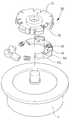
- a device 10 in prior art for holding an optical disk 2 around a rotary shaft (not shown) of a motor 1includes a casing 11 having a plurality of equispaced openings 12 formed around, and a plurality of spring-loaded radial tongues 13 partially extended out from the openings 12 .
- These spring-loaded radial tongues 13retractable into the openings 12 , are provided for engaging with an rounded inner edge 20 of the optical disk 2 to hold and rotate the same disk 2 .
- each radial tongue 13has an upper curved surface 13 1 and a lower curved surface 132 , over which the rounded inner edge 20 of the optical disk 2 may slide to retract the tongue 13 .
- the spring-loaded tongues 13are extended out again until their lower curved surfaces 132 make contact with the rounded inner edge 20 of the disk 2 . With such a contact, the optical disk 2 can be rotated by the tongues 13 synchronously with the rotation of the motor 1 , as shown in FIG. 1 .
- each tongue 13is curved differently from the rounded inner edge 20 of the optical disk 2 . As can be clearly seen in FIGS. 2 and 3 , they make contact with each other only at two points 21 a and 21 b , with an intervening clearance 21 remaining between the lower curved surface 132 and the rounded inner edge 20 of the disk 2 .
- the point contactis more disadvantageous to any optical disk 2 which is thinner than usual. This is because the spring-loaded tongue 13 is extended radially outward a little further and thus exerts a weaker force upon the disk 2 . The reduced force at the contact points 21 a and 21 b impairs the ability of the tongues 13 to hold the disk 2 securely in place, and so the thinner disk 2 may slightly slide relative to the device 10 and rotates at a mismatched speed slower than that of the rotary shaft of the motor 1 .
- the object of the present inventionis to provide a device in which a plurality of spring-loaded radial tongues are shaped in such a manner that the tongues may make contact with an rounded inner edge of the optical disk at a fill contact length, so as to avoid any sliding movement of the disk with respect to the device.
- the present inventionprovides a device including a casing having a plurality of equispaced openings formed around, and a plurality of spring-loaded radial tongues partially extended out from and retractable into the openings.
- Each of the radial tongueshas a lower curved surface with a constant curvature in any imaginary contour line throughout at least one area of the lower curved surface, and the constant curvature is exactly the same as the curvature of the rounded inner edge of the optical disk to be held.
- FIG. 1is a perspective view of a device in prior art for holding an optical disk around a rotary shaft of a motor;
- FIG. 2is an enlarged top view of a spring-loaded radial tongue involved in the device of FIG. 1 ;
- FIG. 3is a cross-sectional view taken along lines 3 — 3 in FIG. 2 ;
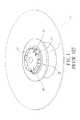
- FIG. 4is an exploded perspective view of a preferred embodiment of a device in accordance with the present invention for holding an optical disk around a rotary shaft of a motor;
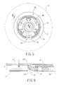
- FIG. 5is a top view, partially cut away, of the device of FIG. 4 ;
- FIG. 6is a cross-sectional view taken along lines 6 — 6 in FIG. 5 , showing an optical disk to be held on the device of FIG. 4 ;
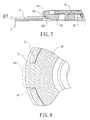
- FIG. 7is a cross-sectional view similar to FIG. 6 , but showing the optical disk held on the device of FIG. 4 ;
- FIG. 8is a cross-sectional view taken along lines 8 — 8 in FIG. 7 .
- FIGS. 4 and 5there is shown a preferred embodiment of an inventive device 30 for holding an optical disk 4 around a rotary shaft (not numbered) of a motor 3 .
- the device 30includes a casing 31 having a plurality of equispaced openings 32 formed around, and a plurality of spring-loaded radial tongues 34 partially extended out from the openings 32 for engagement with an rounded inner edge 40 of the optical disk 4 .
- the casing 31is fastened to the rotary shaft of the motor 3 , and the radial tongues 34 are partially received in the casing 31 .
- the tongues 34are spring-loaded, preferably by helical springs 33 each compressed between adjacent two of the tongues 34 , in such a manner that the tongues 34 has an ability of being retractable radially into the openings 32 of the casing 31 when depressed but extendable radially out again from the openings 32 when released.
- the ability of the radial tongues 34allows the optical disk 4 to be easily held on and removed from the inventive device 30 by sliding its rounded inner edge 40 over the spring-loaded tongues 34 , which are then depressed and released during the movement of the disk 4 in the axial direction of the rotary shaft.
- each radial tongue 34has an upper curved surface 341 and a lower curved surface 342 , cambered inversely and sloped so that the tongue 34 are tapered radially outward.
- the curved surfaces 341 and 342are each provided with a constant curvature at everywhere on any imaginary “contour line” throughout a predetermined area thereof.
- the term “contour line” heremeans a planar curved made by any imaginary horizontal plane which intersects the curved surface 341 or 342 .
- the constant curvature throughout the surfaces 341 and 342is exactly the same as the curvature of the rounded inner edge 40 of the optical disk 4 .
- the spring-loaded radial tongues 34can hold the optical disk 4 in place, with their lower curved surfaces 342 engaged with the rounded inner edge 40 of the disk 4 .
- the lower curved surfaces 342make contact with the rounded inner edge 40 at the full length of a contact line, as clearly shown in FIG. 8 , thereby providing an elongated contact length and hence reducing the possibility of sliding movement of the optical disk 4 with respect to the device 30 .
- any optical disk 40 thinner than usualcan also be securely held in place by the spring-loaded radial tongues 34 , which are now extended radially outward a little further until making contact with the rounded inner edge 40 of the optical disk 4 at the full length of a contact line. This line contact avoids the sliding movement of the optical disk 4 with respect to the tongues 34 .
- this inventionhas the advantage of more securely holding an optical disk 40 , thinner or usual, around the rotary shaft of the motor 3 .
Landscapes
- Motor Or Generator Frames (AREA)
- Holding Or Fastening Of Disk On Rotational Shaft (AREA)
Abstract
Description
1. Field of the Invention
The present invention relates to a device for holding an optical disk around a rotary shaft of a motor and, more particularly, to such a device in which a plurality of spring-loaded radial tongues are shaped in such a manner that the tongues may make contact with the rounded inner edge of the optical disk at a full contact length in spite of the thickness of the disk.
2. Description of Related Art
As shown inFIG. 1 , adevice 10 in prior art for holding anoptical disk 2 around a rotary shaft (not shown) of amotor 1 includes acasing 11 having a plurality ofequispaced openings 12 formed around, and a plurality of spring-loadedradial tongues 13 partially extended out from theopenings 12.
These spring-loadedradial tongues 13, retractable into theopenings 12, are provided for engaging with an roundedinner edge 20 of theoptical disk 2 to hold and rotate thesame disk 2.
Referring toFIGS. 2 and 3 , eachradial tongue 13 has an uppercurved surface 131 and a lowercurved surface 132, over which the roundedinner edge 20 of theoptical disk 2 may slide to retract thetongue 13. When thedisk 2 is held in place around the rotary shaft, the spring-loadedtongues 13 are extended out again until their lowercurved surfaces 132 make contact with the roundedinner edge 20 of thedisk 2. With such a contact, theoptical disk 2 can be rotated by thetongues 13 synchronously with the rotation of themotor 1, as shown in FIG.1.
In theprior art device 10, however, the lowercurved surface 132 of eachtongue 13 is curved differently from the roundedinner edge 20 of theoptical disk 2. As can be clearly seen inFIGS. 2 and 3 , they make contact with each other only at twopoints intervening clearance 21 remaining between the lowercurved surface 132 and the roundedinner edge 20 of thedisk 2.
The point contact is more disadvantageous to anyoptical disk 2 which is thinner than usual. This is because the spring-loadedtongue 13 is extended radially outward a little further and thus exerts a weaker force upon thedisk 2. The reduced force at thecontact points tongues 13 to hold thedisk 2 securely in place, and so thethinner disk 2 may slightly slide relative to thedevice 10 and rotates at a mismatched speed slower than that of the rotary shaft of themotor 1.
The object of the present invention is to provide a device in which a plurality of spring-loaded radial tongues are shaped in such a manner that the tongues may make contact with an rounded inner edge of the optical disk at a fill contact length, so as to avoid any sliding movement of the disk with respect to the device.
To achieve the aforementioned objects, the present invention provides a device including a casing having a plurality of equispaced openings formed around, and a plurality of spring-loaded radial tongues partially extended out from and retractable into the openings. Each of the radial tongues has a lower curved surface with a constant curvature in any imaginary contour line throughout at least one area of the lower curved surface, and the constant curvature is exactly the same as the curvature of the rounded inner edge of the optical disk to be held.
Other objects, advantages and novel features of this invention will become more apparent from the following detailed description when taken in conjunction with the accompanying drawings.
The present invention is now to be described hereinafter in detail by way of a preferred embodiment in reference to drawings.
Referring toFIGS. 4 and 5 , there is shown a preferred embodiment of aninventive device 30 for holding anoptical disk 4 around a rotary shaft (not numbered) of amotor 3. Thedevice 30 includes acasing 31 having a plurality ofequispaced openings 32 formed around, and a plurality of spring-loadedradial tongues 34 partially extended out from theopenings 32 for engagement with an roundedinner edge 40 of theoptical disk 4.
Thecasing 31 is fastened to the rotary shaft of the motor3, and theradial tongues 34 are partially received in thecasing 31. Furthermore, thetongues 34 are spring-loaded, preferably byhelical springs 33 each compressed between adjacent two of thetongues 34, in such a manner that thetongues 34 has an ability of being retractable radially into theopenings 32 of thecasing 31 when depressed but extendable radially out again from theopenings 32 when released.
Referring toFIG. 6 , the ability of theradial tongues 34 allows theoptical disk 4 to be easily held on and removed from theinventive device 30 by sliding its roundedinner edge 40 over the spring-loadedtongues 34, which are then depressed and released during the movement of thedisk 4 in the axial direction of the rotary shaft.
Referring toFIG. 6 , eachradial tongue 34 has an uppercurved surface 341 and a lowercurved surface 342, cambered inversely and sloped so that thetongue 34 are tapered radially outward.
In theinventive device 30, thecurved surfaces curved surface
Furthermore, the constant curvature throughout thesurfaces inner edge 40 of theoptical disk 4.
Referring toFIGS. 7 and 8 , the spring-loadedradial tongues 34 can hold theoptical disk 4 in place, with their lowercurved surfaces 342 engaged with the roundedinner edge 40 of thedisk 4. With the same curvature, the lowercurved surfaces 342 make contact with the roundedinner edge 40 at the full length of a contact line, as clearly shown inFIG. 8 , thereby providing an elongated contact length and hence reducing the possibility of sliding movement of theoptical disk 4 with respect to thedevice 30.
Anyoptical disk 40 thinner than usual can also be securely held in place by the spring-loadedradial tongues 34, which are now extended radially outward a little further until making contact with the roundedinner edge 40 of theoptical disk 4 at the full length of a contact line. This line contact avoids the sliding movement of theoptical disk 4 with respect to thetongues 34.
From the foregoing, it is apparent that this invention has the advantage of more securely holding anoptical disk 40, thinner or usual, around the rotary shaft of themotor 3.
While the principles of this invention have been disclosed in connection with specific embodiments, it should be understood by those skilled in the art that these descriptions are not intended to limit the scope of the invention, and that any modification and variation without departing the spirit of the invention is intended to be covered by the scope of this invention defined only by the appended claims.
Claims (4)
1. A device for holding an optical disk around a rotary shaft of a motor, comprising:
a casing adapted to be fastened to said rotary shaft of said motor; and
a plurality of spring-loaded radial tongue each partially extended out of said casing for engagement with a rounded inner edge of said optical disk, each of said radial tongues having a lower curved surface with a constant curvature in any imaginary contour line throughout at least one area of said lower curved surface, said constant curvature being exactly the same as the curvature of said rounded inner edge of said optical disk;
whereby said lower curved surface may make contact with said rounded inner edge of said optical disk at a full contact length when said radial tongue is engaged with said rounded inner edge of said optical disk in said area of said lower curved surface.
2. The device as claimed inclaim 1 , wherein said casing has a plurality of openings formed around, and wherein said spring-loaded radial tongues are retractable into said openings when being depressed.
3. The device as claimed inclaim 1 further including a plurality of springs each compressed between adjacent two of said spring-loaded radial tongues.
4. The device as claimed inclaim 1 , wherein each of said radial tongues has an upper curved surface with the same curvature as that of said lower curved surface.
Applications Claiming Priority (1)
| Application Number | Priority Date | Filing Date | Title |
|---|---|---|---|
| TW091221579UTW555132U (en) | 2002-12-25 | 2002-12-25 | Disk clamper device |
Publications (2)
| Publication Number | Publication Date |
|---|---|
| US20040205803A1 US20040205803A1 (en) | 2004-10-14 |
| US6845512B2true US6845512B2 (en) | 2005-01-18 |
Family
ID=31975455
Family Applications (1)
| Application Number | Title | Priority Date | Filing Date |
|---|---|---|---|
| US10/352,142Expired - Fee RelatedUS6845512B2 (en) | 2002-12-25 | 2003-01-28 | Device with spring-loaded curved tongues for holding an optical disk around a rotary shaft of a motor |
Country Status (2)
| Country | Link |
|---|---|
| US (1) | US6845512B2 (en) |
| TW (1) | TW555132U (en) |
Cited By (32)
| Publication number | Priority date | Publication date | Assignee | Title |
|---|---|---|---|---|
| US20030034051A1 (en)* | 2000-06-14 | 2003-02-20 | The Procter & Gamble Company | Article for deionization of water |
| US20040208301A1 (en)* | 2003-04-18 | 2004-10-21 | Urban Blake R. | Dynamic caller ID messaging |
| US20040209640A1 (en)* | 2003-04-18 | 2004-10-21 | Urban Blake R. | Private Caller ID messaging |
| US20040244024A1 (en)* | 2003-05-27 | 2004-12-02 | Sunonwealth Electric Machine Industry Co., Ltd. | Positioning structure of a clamping device of a disc carrier assembly |
| US20040242212A1 (en)* | 2003-05-29 | 2004-12-02 | James Bacon | Caller identification device and method of operation thereof |
| US20040248560A1 (en)* | 2001-08-14 | 2004-12-09 | Bedingfield James C. | Method for using ain to deliver caller ID to text/alpha-numeric pagers as well as other wireless devices, for calls delivered to wireless network |
| US20050073999A1 (en)* | 2002-05-13 | 2005-04-07 | Bellsouth Intellectual Property Corporation | Delivery of profile-based third party content associated with an incoming communication |
| US20050107074A1 (en)* | 2003-11-13 | 2005-05-19 | Samuel Zellner | Method, system, and storage medium for providing comprehensive originator identification services |
| US20060002540A1 (en)* | 2004-07-02 | 2006-01-05 | Barrett Kreiner | Real-time customer service representative workload management |
| US20060013375A1 (en)* | 2004-07-15 | 2006-01-19 | Donald Smith | Methods of providing caller identification information and related registries and radiotelephone networks |
| US20060062369A1 (en)* | 2004-01-12 | 2006-03-23 | Kent Larry G Jr | Intelligent remote caller ID |
| US20060245420A1 (en)* | 2002-07-23 | 2006-11-02 | Bellsouth Intellectual Property Corporation | System and Method for Gathering Information Related to a Geographical Location of a Caller in an Internet-Based Communication System |
| US20060270392A1 (en)* | 2002-07-23 | 2006-11-30 | Bellsouth Intellectual Property Corporation | System and Method for Gathering Information Related to a Geographical Location of a Callee in a Public Switched Telephone Network |
| US20070064911A1 (en)* | 2001-08-14 | 2007-03-22 | Bedingfield James C Sr | Method for using ain to deliver caller ID to text/alpha-numeric pagers as well as other wireless devices, for calls delivered to landline networks |
| US7254226B1 (en) | 2001-05-08 | 2007-08-07 | At&T Intellectual Property, Inc. | Call waiting priority alert |
| US20070195942A1 (en)* | 2001-09-28 | 2007-08-23 | Bellsouth Intellectual Property Corporation | Systems and Methods for Providing User Profile Information in Conjunction with an Enhanced Caller Information System |
| US7295656B2 (en) | 2001-06-25 | 2007-11-13 | At&T Bls Intellectual Property, Inc. | Audio caller identification |
| US7315618B1 (en) | 2001-12-27 | 2008-01-01 | At&T Bls Intellectual Property, Inc. | Voice caller ID |
| US20080059984A1 (en)* | 2006-09-04 | 2008-03-06 | Nidec Corporation | Chucking Device, and Motor and Disc Drive Device Having Loaded Thereon a Chucking Device |
| US20080112552A1 (en)* | 2003-04-18 | 2008-05-15 | Bellsouth Intellectual Property Corporation | Caller ID Messaging Telecommunications Services |
| US7385992B1 (en) | 2002-05-13 | 2008-06-10 | At&T Delaware Intellectual Property, Inc. | Internet caller-ID integration |
| US7388949B2 (en) | 2000-12-28 | 2008-06-17 | At&T Delaware Intellectual Property, Inc. | System and method for audio caller identification service |
| US7463727B2 (en) | 2003-04-18 | 2008-12-09 | At&T International Property, I, L.P. | Caller ID messaging device |
| US20090117886A1 (en)* | 2003-04-18 | 2009-05-07 | AT&T Intellectual Property I,L.P. f/k/a BellSouth Intellectual Property Corporation | Caller ID Messaging |
| US20090119690A1 (en)* | 2007-11-05 | 2009-05-07 | Samsung Electro-Mechanics Co., Ltd. | Disk chucking device and disk driving device having the same |
| US7586898B1 (en) | 2002-05-13 | 2009-09-08 | At&T Intellectual Property, I, L.P. | Third party content for internet caller-ID messages |
| US7623645B1 (en) | 2002-07-23 | 2009-11-24 | At&T Intellectual Property, I, L.P. | System and method for gathering information related to a geographical location of a caller in a public switched telephone network |
| US7634256B2 (en) | 2001-11-06 | 2009-12-15 | At&T Intellectual Property, I, L.P. | Caller identification queue for wireless telephones |
| US7672444B2 (en) | 2003-12-24 | 2010-03-02 | At&T Intellectual Property, I, L.P. | Client survey systems and methods using caller identification information |
| US7929675B2 (en) | 2001-06-25 | 2011-04-19 | At&T Intellectual Property I, L.P. | Visual caller identification |
| US8160226B2 (en) | 2007-08-22 | 2012-04-17 | At&T Intellectual Property I, L.P. | Key word programmable caller ID |
| US8243909B2 (en) | 2007-08-22 | 2012-08-14 | At&T Intellectual Property I, L.P. | Programmable caller ID |
Families Citing this family (6)
| Publication number | Priority date | Publication date | Assignee | Title |
|---|---|---|---|---|
| JP3946103B2 (en)* | 2002-08-08 | 2007-07-18 | パイオニア株式会社 | Clamp / alignment mechanism, information reproduction mechanism and information recording mechanism |
| TWI222262B (en)* | 2003-07-24 | 2004-10-11 | Delta Electronics Inc | Spindle motor centering device |
| JP4493670B2 (en)* | 2007-02-20 | 2010-06-30 | 三洋電機株式会社 | Disk drive |
| JP5076573B2 (en)* | 2007-03-19 | 2012-11-21 | 日本電産株式会社 | Motor equipped with chucking device, and disk drive equipped with this motor |
| JP4992497B2 (en)* | 2007-03-19 | 2012-08-08 | 日本電産株式会社 | Motor equipped with chucking device, and disk drive equipped with this motor |
| JP4978257B2 (en)* | 2007-03-19 | 2012-07-18 | 日本電産株式会社 | Motor equipped with chucking device, and disk drive equipped with this motor |
Citations (5)
| Publication number | Priority date | Publication date | Assignee | Title |
|---|---|---|---|---|
| US6040649A (en)* | 1999-01-11 | 2000-03-21 | Sunonwealth Electric Machine Industry Co., Ltd. | Support structure apparatus for a spindle motor of a compact disc machine |
| US6363048B1 (en)* | 1999-05-24 | 2002-03-26 | Industrial Technology Research Institute | Disc clamp mechanism |
| US6487162B1 (en)* | 2000-03-01 | 2002-11-26 | Industrial Technology Research Institute | Disc clamping device with self lock elements |
| US6525441B2 (en)* | 2000-03-23 | 2003-02-25 | Tokyo Parts Industrial Co., Ltd. | Spindle motor having disc mounting portion |
| US6611490B1 (en)* | 1998-11-30 | 2003-08-26 | Koninklijke Philips Electronics N.V. | Clamping device for a disc-shaped information carrier |
- 2002
- 2002-12-25TWTW091221579Upatent/TW555132U/enunknown
- 2003
- 2003-01-28USUS10/352,142patent/US6845512B2/ennot_activeExpired - Fee Related
Patent Citations (5)
| Publication number | Priority date | Publication date | Assignee | Title |
|---|---|---|---|---|
| US6611490B1 (en)* | 1998-11-30 | 2003-08-26 | Koninklijke Philips Electronics N.V. | Clamping device for a disc-shaped information carrier |
| US6040649A (en)* | 1999-01-11 | 2000-03-21 | Sunonwealth Electric Machine Industry Co., Ltd. | Support structure apparatus for a spindle motor of a compact disc machine |
| US6363048B1 (en)* | 1999-05-24 | 2002-03-26 | Industrial Technology Research Institute | Disc clamp mechanism |
| US6487162B1 (en)* | 2000-03-01 | 2002-11-26 | Industrial Technology Research Institute | Disc clamping device with self lock elements |
| US6525441B2 (en)* | 2000-03-23 | 2003-02-25 | Tokyo Parts Industrial Co., Ltd. | Spindle motor having disc mounting portion |
Cited By (60)
| Publication number | Priority date | Publication date | Assignee | Title |
|---|---|---|---|---|
| US20030034051A1 (en)* | 2000-06-14 | 2003-02-20 | The Procter & Gamble Company | Article for deionization of water |
| US7388949B2 (en) | 2000-12-28 | 2008-06-17 | At&T Delaware Intellectual Property, Inc. | System and method for audio caller identification service |
| US7254226B1 (en) | 2001-05-08 | 2007-08-07 | At&T Intellectual Property, Inc. | Call waiting priority alert |
| US7295656B2 (en) | 2001-06-25 | 2007-11-13 | At&T Bls Intellectual Property, Inc. | Audio caller identification |
| US7929675B2 (en) | 2001-06-25 | 2011-04-19 | At&T Intellectual Property I, L.P. | Visual caller identification |
| US20080056465A1 (en)* | 2001-06-25 | 2008-03-06 | Bellsouth Intellectual Property Corporation | Audio Caller Identification |
| US7463724B2 (en) | 2001-06-25 | 2008-12-09 | At&T Intellectual Property, I.L.P. | Audio caller identification |
| US7403768B2 (en) | 2001-08-14 | 2008-07-22 | At&T Delaware Intellectual Property, Inc. | Method for using AIN to deliver caller ID to text/alpha-numeric pagers as well as other wireless devices, for calls delivered to wireless network |
| US20040248560A1 (en)* | 2001-08-14 | 2004-12-09 | Bedingfield James C. | Method for using ain to deliver caller ID to text/alpha-numeric pagers as well as other wireless devices, for calls delivered to wireless network |
| US7315614B2 (en) | 2001-08-14 | 2008-01-01 | At&T Delaware Intellectual Property, Inc. | Remote notification of communications |
| US8019064B2 (en) | 2001-08-14 | 2011-09-13 | At&T Intellectual Property I, L.P. | Remote notification of communications |
| US20070064911A1 (en)* | 2001-08-14 | 2007-03-22 | Bedingfield James C Sr | Method for using ain to deliver caller ID to text/alpha-numeric pagers as well as other wireless devices, for calls delivered to landline networks |
| US20070195942A1 (en)* | 2001-09-28 | 2007-08-23 | Bellsouth Intellectual Property Corporation | Systems and Methods for Providing User Profile Information in Conjunction with an Enhanced Caller Information System |
| US7269249B2 (en) | 2001-09-28 | 2007-09-11 | At&T Bls Intellectual Property, Inc. | Systems and methods for providing user profile information in conjunction with an enhanced caller information system |
| US8155287B2 (en) | 2001-09-28 | 2012-04-10 | At&T Intellectual Property I, L.P. | Systems and methods for providing user profile information in conjunction with an enhanced caller information system |
| US7634256B2 (en) | 2001-11-06 | 2009-12-15 | At&T Intellectual Property, I, L.P. | Caller identification queue for wireless telephones |
| US7418096B2 (en) | 2001-12-27 | 2008-08-26 | At&T Intellectual Property I, L.P. | Voice caller ID |
| US8139758B2 (en) | 2001-12-27 | 2012-03-20 | At&T Intellectual Property I, L.P. | Voice caller ID |
| US20080310615A1 (en)* | 2001-12-27 | 2008-12-18 | Bellsouth Intellectual Property Corporation | Voice Caller ID |
| US7315618B1 (en) | 2001-12-27 | 2008-01-01 | At&T Bls Intellectual Property, Inc. | Voice caller ID |
| US7586898B1 (en) | 2002-05-13 | 2009-09-08 | At&T Intellectual Property, I, L.P. | Third party content for internet caller-ID messages |
| US20050073999A1 (en)* | 2002-05-13 | 2005-04-07 | Bellsouth Intellectual Property Corporation | Delivery of profile-based third party content associated with an incoming communication |
| US7385992B1 (en) | 2002-05-13 | 2008-06-10 | At&T Delaware Intellectual Property, Inc. | Internet caller-ID integration |
| US20060245420A1 (en)* | 2002-07-23 | 2006-11-02 | Bellsouth Intellectual Property Corporation | System and Method for Gathering Information Related to a Geographical Location of a Caller in an Internet-Based Communication System |
| US7623645B1 (en) | 2002-07-23 | 2009-11-24 | At&T Intellectual Property, I, L.P. | System and method for gathering information related to a geographical location of a caller in a public switched telephone network |
| US9532175B2 (en) | 2002-07-23 | 2016-12-27 | At&T Intellectual Property I, L.P. | System and method for gathering information related to a geographical location of a callee in a public switched telephone network |
| US20100086117A1 (en)* | 2002-07-23 | 2010-04-08 | At&T Intellectual Property I, L.P. F/K/A Bellsouth Intellectual Property Corporation | System And Method For Gathering Information Related To A Geographical Location Of A Caller In A Public Switched Telephone Network |
| US20060270392A1 (en)* | 2002-07-23 | 2006-11-30 | Bellsouth Intellectual Property Corporation | System and Method for Gathering Information Related to a Geographical Location of a Callee in a Public Switched Telephone Network |
| US8452268B2 (en) | 2002-07-23 | 2013-05-28 | At&T Intellectual Property I, L.P. | System and method for gathering information related to a geographical location of a callee in a public switched telephone network |
| US7978841B2 (en) | 2002-07-23 | 2011-07-12 | At&T Intellectual Property I, L.P. | System and method for gathering information related to a geographical location of a caller in a public switched telephone network |
| US20080112552A1 (en)* | 2003-04-18 | 2008-05-15 | Bellsouth Intellectual Property Corporation | Caller ID Messaging Telecommunications Services |
| US20040208301A1 (en)* | 2003-04-18 | 2004-10-21 | Urban Blake R. | Dynamic caller ID messaging |
| US8073121B2 (en) | 2003-04-18 | 2011-12-06 | At&T Intellectual Property I, L.P. | Caller ID messaging |
| US20090117886A1 (en)* | 2003-04-18 | 2009-05-07 | AT&T Intellectual Property I,L.P. f/k/a BellSouth Intellectual Property Corporation | Caller ID Messaging |
| US20040209640A1 (en)* | 2003-04-18 | 2004-10-21 | Urban Blake R. | Private Caller ID messaging |
| US7564960B2 (en) | 2003-04-18 | 2009-07-21 | At&T Intellectual Property, I, L.P. | Methods, systems and computer program products for dynamic caller ID messaging |
| US7280646B2 (en) | 2003-04-18 | 2007-10-09 | At&T Bls Intellectual Property, Inc. | Dynamic Caller ID messaging |
| US7978833B2 (en) | 2003-04-18 | 2011-07-12 | At&T Intellectual Property I, L.P. | Private caller ID messaging |
| US7463727B2 (en) | 2003-04-18 | 2008-12-09 | At&T International Property, I, L.P. | Caller ID messaging device |
| US20040244024A1 (en)* | 2003-05-27 | 2004-12-02 | Sunonwealth Electric Machine Industry Co., Ltd. | Positioning structure of a clamping device of a disc carrier assembly |
| US6993779B2 (en)* | 2003-05-27 | 2006-01-31 | Sunonwealth Electric Machine Industry Co., Ltd. | Positioning structure of a clamping device of a disc carrier assembly |
| US20040242212A1 (en)* | 2003-05-29 | 2004-12-02 | James Bacon | Caller identification device and method of operation thereof |
| US7269412B2 (en) | 2003-05-29 | 2007-09-11 | At&T Bls Intellectual Property, Inc. | Caller identification device and method of operation thereof |
| US7623849B2 (en) | 2003-11-13 | 2009-11-24 | At&T Intellectual Property, I, L.P. | Method, system, and storage medium for providing comprehensive originator identification services |
| US7945253B2 (en) | 2003-11-13 | 2011-05-17 | At&T Intellectual Property I, L.P. | Method, system, and storage medium for providing comprehensive originator identification services |
| US20050107074A1 (en)* | 2003-11-13 | 2005-05-19 | Samuel Zellner | Method, system, and storage medium for providing comprehensive originator identification services |
| US7672444B2 (en) | 2003-12-24 | 2010-03-02 | At&T Intellectual Property, I, L.P. | Client survey systems and methods using caller identification information |
| US8102994B2 (en) | 2003-12-24 | 2012-01-24 | At&T Intellectual Property I, L.P. | Client survey systems and methods using caller identification information |
| US20060062369A1 (en)* | 2004-01-12 | 2006-03-23 | Kent Larry G Jr | Intelligent remote caller ID |
| US20060002540A1 (en)* | 2004-07-02 | 2006-01-05 | Barrett Kreiner | Real-time customer service representative workload management |
| US20060013375A1 (en)* | 2004-07-15 | 2006-01-19 | Donald Smith | Methods of providing caller identification information and related registries and radiotelephone networks |
| US8195136B2 (en) | 2004-07-15 | 2012-06-05 | At&T Intellectual Property I, L.P. | Methods of providing caller identification information and related registries and radiotelephone networks |
| US7802272B2 (en)* | 2006-09-04 | 2010-09-21 | Nidec Corporation | Chucking device, and motor and disc drive device having loaded thereon a chucking device |
| US20080059984A1 (en)* | 2006-09-04 | 2008-03-06 | Nidec Corporation | Chucking Device, and Motor and Disc Drive Device Having Loaded Thereon a Chucking Device |
| US8160226B2 (en) | 2007-08-22 | 2012-04-17 | At&T Intellectual Property I, L.P. | Key word programmable caller ID |
| US8243909B2 (en) | 2007-08-22 | 2012-08-14 | At&T Intellectual Property I, L.P. | Programmable caller ID |
| US8416938B2 (en) | 2007-08-22 | 2013-04-09 | At&T Intellectual Property I, L.P. | Programmable caller ID |
| US8787549B2 (en) | 2007-08-22 | 2014-07-22 | At&T Intellectual Property I, L.P. | Programmable caller ID |
| US7984461B2 (en)* | 2007-11-05 | 2011-07-19 | Samsung Electro-Mechanics Co., Ltd. | Disk chucking device and disk driving device having the same |
| US20090119690A1 (en)* | 2007-11-05 | 2009-05-07 | Samsung Electro-Mechanics Co., Ltd. | Disk chucking device and disk driving device having the same |
Also Published As
| Publication number | Publication date |
|---|---|
| TW555132U (en) | 2003-09-21 |
| US20040205803A1 (en) | 2004-10-14 |
Similar Documents
| Publication | Publication Date | Title |
|---|---|---|
| US6845512B2 (en) | Device with spring-loaded curved tongues for holding an optical disk around a rotary shaft of a motor | |
| US6230365B1 (en) | Hinge for a notebook computer | |
| WO2002084056A3 (en) | Clip friction hinge with housing | |
| JP2003532548A (en) | Solid drills for machine tools | |
| CN109899366A (en) | Simple and reliable connector is installed | |
| EP3176449B1 (en) | Thrust bearing and manufacturing method for same | |
| CN105276107A (en) | Pulley device for chain or belt | |
| US20060291764A1 (en) | Clamping arrangement for securing an annular component to a shaft | |
| CN104896047B (en) | Intermittent motion transmission mechanism | |
| EP3828447B1 (en) | Sealing device | |
| JP2001162553A (en) | Mounting jig | |
| US20210131567A1 (en) | Sealing device | |
| US20060285916A1 (en) | Pivotal device | |
| US7121391B2 (en) | One-way clutch | |
| JPH0712138A (en) | Simultaneously operated swivel joint | |
| US20190040656A1 (en) | Spinning knob | |
| US7178876B2 (en) | Belt lock with fastening device | |
| CN107630920A (en) | A kind of semi-automatic rotating assembly | |
| JP2004185774A5 (en) | ||
| US6986584B2 (en) | Arrangement for a rotatable eyepiece cap | |
| US20060254027A1 (en) | Hinge | |
| JPH04135584A (en) | pinball game machine windmill | |
| JP6003400B2 (en) | Ball screw and ball screw seal mounting method | |
| US4328440A (en) | Commutator | |
| JP2630708B2 (en) | Rotary switch |
Legal Events
| Date | Code | Title | Description |
|---|---|---|---|
| AS | Assignment | Owner name:SUNONWEALTH ELECTRIC MACHINE INDUSTRY CO., LTD., T Free format text:ASSIGNMENT OF ASSIGNORS INTEREST;ASSIGNORS:HORNG, ALEX;YIN, TSO-KUO;REEL/FRAME:013708/0932 Effective date:20030124 | |
| FPAY | Fee payment | Year of fee payment:4 | |
| REMI | Maintenance fee reminder mailed | ||
| LAPS | Lapse for failure to pay maintenance fees | ||
| STCH | Information on status: patent discontinuation | Free format text:PATENT EXPIRED DUE TO NONPAYMENT OF MAINTENANCE FEES UNDER 37 CFR 1.362 | |
| FP | Expired due to failure to pay maintenance fee | Effective date:20130118 |