US6845190B1 - Control of an optical fiber scanner - Google Patents
Control of an optical fiber scannerDownload PDFInfo
- Publication number
- US6845190B1 US6845190B1US10/305,914US30591402AUS6845190B1US 6845190 B1US6845190 B1US 6845190B1US 30591402 AUS30591402 AUS 30591402AUS 6845190 B1US6845190 B1US 6845190B1
- Authority
- US
- United States
- Prior art keywords
- signal
- amplitude
- controller
- optical scanner
- phase
- Prior art date
- Legal status (The legal status is an assumption and is not a legal conclusion. Google has not performed a legal analysis and makes no representation as to the accuracy of the status listed.)
- Expired - Lifetime, expires
Links
- 239000013307optical fiberSubstances0.000titleclaimsabstractdescription176
- 230000003287optical effectEffects0.000claimsabstractdescription120
- 230000033001locomotionEffects0.000claimsdescription34
- 238000000034methodMethods0.000claimsdescription31
- 230000004044responseEffects0.000claimsdescription25
- 230000010287polarizationEffects0.000claimsdescription14
- 238000005452bendingMethods0.000claimsdescription10
- 230000001133accelerationEffects0.000claimsdescription7
- 230000000087stabilizing effectEffects0.000claims2
- 238000005312nonlinear dynamicMethods0.000claims1
- 239000000835fiberSubstances0.000abstractdescription23
- 230000003044adaptive effectEffects0.000abstractdescription4
- 238000001824photoionisation detectionMethods0.000abstract2
- 238000005259measurementMethods0.000description14
- 230000006870functionEffects0.000description11
- 238000010586diagramMethods0.000description10
- 238000006073displacement reactionMethods0.000description10
- 238000013016dampingMethods0.000description7
- 238000004088simulationMethods0.000description7
- 230000001052transient effectEffects0.000description7
- 230000008901benefitEffects0.000description6
- 230000008859changeEffects0.000description6
- 230000008878couplingEffects0.000description5
- 238000010168coupling processMethods0.000description5
- 238000005859coupling reactionMethods0.000description5
- 230000009022nonlinear effectEffects0.000description5
- 230000010363phase shiftEffects0.000description5
- 238000004519manufacturing processMethods0.000description4
- 230000002336repolarizationEffects0.000description4
- 230000003321amplificationEffects0.000description3
- 238000013459approachMethods0.000description3
- 238000004891communicationMethods0.000description3
- 230000001419dependent effectEffects0.000description3
- 238000013461designMethods0.000description3
- 238000003199nucleic acid amplification methodMethods0.000description3
- 230000001360synchronised effectEffects0.000description3
- 230000018199S phaseEffects0.000description2
- 230000032683agingEffects0.000description2
- 238000010009beatingMethods0.000description2
- 230000003247decreasing effectEffects0.000description2
- 230000001934delayEffects0.000description2
- 230000009977dual effectEffects0.000description2
- 230000007613environmental effectEffects0.000description2
- 238000003384imaging methodMethods0.000description2
- 230000028161membrane depolarizationEffects0.000description2
- 238000012986modificationMethods0.000description2
- 230000004048modificationEffects0.000description2
- 238000012544monitoring processMethods0.000description2
- 230000002829reductive effectEffects0.000description2
- 210000001525retinaAnatomy0.000description2
- 238000001065shear force microscopyMethods0.000description2
- 230000035882stressEffects0.000description2
- 238000012360testing methodMethods0.000description2
- VYZAMTAEIAYCRO-UHFFFAOYSA-NChromiumChemical compound[Cr]VYZAMTAEIAYCRO-UHFFFAOYSA-N0.000description1
- 241000197200Gallinago mediaSpecies0.000description1
- 229910000831SteelInorganic materials0.000description1
- 230000002411adverseEffects0.000description1
- 229910052782aluminiumInorganic materials0.000description1
- XAGFODPZIPBFFR-UHFFFAOYSA-NaluminiumChemical compound[Al]XAGFODPZIPBFFR-UHFFFAOYSA-N0.000description1
- 238000004630atomic force microscopyMethods0.000description1
- 230000004888barrier functionEffects0.000description1
- 230000005540biological transmissionEffects0.000description1
- 230000015556catabolic processEffects0.000description1
- 230000001413cellular effectEffects0.000description1
- 230000001427coherent effectEffects0.000description1
- 239000012141concentrateSubstances0.000description1
- 238000010276constructionMethods0.000description1
- 238000012937correctionMethods0.000description1
- 238000005336crackingMethods0.000description1
- 238000006880cross-coupling reactionMethods0.000description1
- 230000003111delayed effectEffects0.000description1
- 230000006866deteriorationEffects0.000description1
- 238000002059diagnostic imagingMethods0.000description1
- 230000000694effectsEffects0.000description1
- 238000010894electron beam technologyMethods0.000description1
- 238000005516engineering processMethods0.000description1
- 230000005284excitationEffects0.000description1
- 239000013305flexible fiberSubstances0.000description1
- 238000007689inspectionMethods0.000description1
- 230000003993interactionEffects0.000description1
- 230000000670limiting effectEffects0.000description1
- 230000005923long-lasting effectEffects0.000description1
- 238000013507mappingMethods0.000description1
- 239000000463materialSubstances0.000description1
- 230000007246mechanismEffects0.000description1
- 229910052751metalInorganic materials0.000description1
- 239000002184metalSubstances0.000description1
- 238000004651near-field scanning optical microscopyMethods0.000description1
- 230000008447perceptionEffects0.000description1
- 230000000737periodic effectEffects0.000description1
- 229920000729poly(L-lysine) polymerPolymers0.000description1
- 230000008569processEffects0.000description1
- 230000001681protective effectEffects0.000description1
- 230000009467reductionEffects0.000description1
- 230000008439repair processEffects0.000description1
- 230000002207retinal effectEffects0.000description1
- 239000000523sampleSubstances0.000description1
- 238000005070samplingMethods0.000description1
- 230000006641stabilisationEffects0.000description1
- 238000011105stabilizationMethods0.000description1
- 239000010959steelSubstances0.000description1
- 230000000007visual effectEffects0.000description1
Images


Classifications
- G—PHYSICS
- G02—OPTICS
- G02B—OPTICAL ELEMENTS, SYSTEMS OR APPARATUS
- G02B26/00—Optical devices or arrangements for the control of light using movable or deformable optical elements
- G02B26/08—Optical devices or arrangements for the control of light using movable or deformable optical elements for controlling the direction of light
- G02B26/10—Scanning systems
- A—HUMAN NECESSITIES
- A61—MEDICAL OR VETERINARY SCIENCE; HYGIENE
- A61B—DIAGNOSIS; SURGERY; IDENTIFICATION
- A61B1/00—Instruments for performing medical examinations of the interior of cavities or tubes of the body by visual or photographical inspection, e.g. endoscopes; Illuminating arrangements therefor
- A61B1/00064—Constructional details of the endoscope body
- A61B1/00071—Insertion part of the endoscope body
- A61B1/0008—Insertion part of the endoscope body characterised by distal tip features
- A61B1/00097—Sensors
- A—HUMAN NECESSITIES
- A61—MEDICAL OR VETERINARY SCIENCE; HYGIENE
- A61B—DIAGNOSIS; SURGERY; IDENTIFICATION
- A61B1/00—Instruments for performing medical examinations of the interior of cavities or tubes of the body by visual or photographical inspection, e.g. endoscopes; Illuminating arrangements therefor
- A61B1/00163—Optical arrangements
- A61B1/00172—Optical arrangements with means for scanning
- G—PHYSICS
- G02—OPTICS
- G02B—OPTICAL ELEMENTS, SYSTEMS OR APPARATUS
- G02B6/00—Light guides; Structural details of arrangements comprising light guides and other optical elements, e.g. couplings
- G02B6/24—Coupling light guides
- G02B6/26—Optical coupling means
- G02B6/262—Optical details of coupling light into, or out of, or between fibre ends, e.g. special fibre end shapes or associated optical elements
- G—PHYSICS
- G02—OPTICS
- G02B—OPTICAL ELEMENTS, SYSTEMS OR APPARATUS
- G02B6/00—Light guides; Structural details of arrangements comprising light guides and other optical elements, e.g. couplings
- G02B6/24—Coupling light guides
- G02B6/26—Optical coupling means
- G02B6/32—Optical coupling means having lens focusing means positioned between opposed fibre ends
- G—PHYSICS
- G02—OPTICS
- G02B—OPTICAL ELEMENTS, SYSTEMS OR APPARATUS
- G02B6/00—Light guides; Structural details of arrangements comprising light guides and other optical elements, e.g. couplings
- G02B6/24—Coupling light guides
- G02B6/26—Optical coupling means
- G02B6/35—Optical coupling means having switching means
- G02B6/3502—Optical coupling means having switching means involving direct waveguide displacement, e.g. cantilever type waveguide displacement involving waveguide bending, or displacing an interposed waveguide between stationary waveguides
- G02B6/3504—Rotating, tilting or pivoting the waveguides, or with the waveguides describing a curved path
- G—PHYSICS
- G02—OPTICS
- G02B—OPTICAL ELEMENTS, SYSTEMS OR APPARATUS
- G02B6/00—Light guides; Structural details of arrangements comprising light guides and other optical elements, e.g. couplings
- G02B6/24—Coupling light guides
- G02B6/26—Optical coupling means
- G02B6/35—Optical coupling means having switching means
- G02B6/3586—Control or adjustment details, e.g. calibrating
- G02B6/359—Control or adjustment details, e.g. calibrating of the position of the moving element itself during switching, i.e. without monitoring the switched beams
Definitions
- the present inventiongenerally relates to controls for an optical scanner, and more specifically, to controls for a resonant optical scanner that is used either for image acquisition or display of an image, wherein the controls determine the movement of a cantilevered distal tip of the optical fiber relative to an adjacent surface.
- an optical fiber scannerWhen driven to move at resonance or near resonance, an optical fiber scanner can be used for image display and acquisition, as well as the basis of several fiber optic sensors, e.g. media density, temperature, or proximity to a surface (atomic force microscopy).
- Most optical scanning applicationsuse a moving mirror, either rotating or oscillating.
- a laser beamis often projected onto the moving mirror to scan the beam across a specified linear or two-dimensional (2D) (raster) pattern at a frequency that is sufficient for the particular application.
- 2Dtwo-dimensional
- the field of view (FOV)is determined by the scanning amplitude and the particular optical design.
- rateFor ubiquitous raster scanning displays, such as cathode ray tubes (CRTs) used in televisions and computer monitors, the display refresh rate is typically 30 to 60 Hz.
- a CRTemploys an electron beam for scanning an electro-optical display screen
- scan frequency and amplitudethat determine the FOV
- the same requirements for scan frequency and amplitudegenerally apply for all types of scanning displays.
- SVGAsuper video graphics array
- the minimum horizontal scan ratesare 40 kHz for unidirectional and 18 kHz for bi-directional scanning.
- micro-optical displaysAs well as small optical sensors, optical switches, and scanning image acquisition systems.
- a low cost micro-optical scanneris essential for spectacle-mounted, retinal light scanning displays and micro-displays that may be embedded in future cellular telephones.
- a commercial need for low cost, large-scale (panoramic) optical displaysbecause larger CRT displays are uneconomical in energy and space.
- optical sensing and switchingespecially in conjunction with fiber-optic sensing and communication applications.
- micro-optical scanners with a wide FOVhas been the most significant barrier for reducing the size of scanning image acquisition systems for use in surveillance, industrial inspection and repair, machine and robotic vision systems, micro-barcode scanners, and minimally-invasive medical imaging, e.g., a flexible single fiber scanning endoscope (SFSE).
- SFSEflexible single fiber scanning endoscope
- optical fiber scannershave been developed that are relatively compact and usable for either image acquisition or image display.
- the scanning optical fiberis preferably actuated to move either in one dimension or in two dimensions using, for example, piezoelectric bimorph or tube actuators.
- piezoelectric bimorph or tube actuatorsBy tapering a distal end of the optical fiber to a relatively small size, large FOVs have been obtained as the optical fiber is driven to move relatively to a surface.
- one or more laser light sources coupled to the proximal end of the optical fiberprovide light that is emitted from the distal tip as it scans a surface.
- the actuator(s)can cause the distal tip to scan the surface in a linear motion or a space-filling motion, such as a raster pattern, a spiral pattern, a propeller pattern, various Lissajous scanning patterns, and in other desired patterns.
- One or more photodetectors disposed adjacent to the distal tip (or elsewhere, if other optical fibers convey the reflected light to remote photo detectors)respond to light reflected from the surface, producing a signal that can be processed or employed to produce an image of the surface being scanned.
- a modulated light sourceresponds to an input signal producing light that is then emitted by the distal tip of the scanning optical fiber as it scans either an adjacent surface, or a user's eye (i.e., retina).
- the modulated light emittedis applied to create a pixilated array of light spots on the surface or on the retina of a user's eye, forming an image.
- these and various other applications of a scanning optical fiberrequire control of the actuators employed to cause the distal tip of the optical fiber to move in the desired scanning pattern.
- Various problemsmust be addressed by the control scheme employed for this purpose.
- spiral pattern scanscan be implemented efficiently with a very compact scanning optical fiber
- a spiral pattern of light emitted by a scanning optical fiberis subject to distortion that adversely affects the spiral pattern.
- simulationshave been run to discover the source of the distortions or breakdown of the spiral scan pattern.
- the optical fiberacts as a band-pass filter (amplifier) between an actuator input and the resulting motion of the optical fiber (i.e., its scanning motion).
- band-pass filteramplifier
- many of the frequency components of complex scan patternse.g., square or triangle waves
- the optical fiber scannersare usually used to produce nearly sinusoidal scans, typically at a constant amplitude and phase, with respect to the drive signal applied as an actuator input.
- the amplitude and phase response of an optical fiber scanmay vary greatly between scanners and within the same scanner over time, due to differences or changes in the scanner resonant properties. Between scanners, differences in resonant properties are due to manufacturing variability either in the length of the fiber, quality of actuator/fiber coupling, or actuator efficiency. A single scanner's resonant properties may change due to environmental effects (temperature changes) or aging (fiber cracking, actuator/fiber coupling deterioration). Generally, it is preferable to achieve a consistent behavior between scanners, and within the same scanner over time.
- the low mass and light damping of the fiberwhile essential for large resonant amplification, also allow disturbances to persist for long periods of time.
- optical fibers undergoing large deflectionsexhibit nonlinear behavior. This behavior includes amplitude and phase shifts in the output that are dependent on the amplitude of the input, cross-coupling of the optical fiber vibration axes, and possible bi-stable output amplitude. This nonlinear behavior produces undesirable scan distortion or inconsistencies.
- the present inventionis thus directed to developing controllers for an optical scanner.
- the disclosed preferred embodimentsare directed to controllers for a cantilevered light guide or resonant optical fiber.
- the term “light guide”is intended to encompass wave guides, optical fibers, and other structures that convey light along a desired path.
- optical scanneris intended to refer to a vibrating device that projects, directs, or redirects light in a desired direction and includes without limitation, vibrating mirrors and light guides.
- a first aspect of the present inventionis directed to a controller for an optical scanner that is driven to move in a desired pattern.
- the controllerincludes a reference phase signal source that produces a reference phase signal, and includes a phase control.
- the phase controlis adapted to couple to a sensor to receive a position signal indicative of a position of a moving portion of the optical scanner.
- the phase controlis coupled to the reference phase signal source to receive the reference phase signal and uses the reference phase signal and the position signal to produce a phase signal output.
- the controllerhas an amplitude reference source for producing an amplitude reference signal.
- An amplitude controlis included and is adapted to couple to a sensor to receive the position signal.
- the amplitude controlis also coupled to the amplitude reference signal source to receive the amplitude reference signal and produces an amplitude signal output in response to the position signal and the amplitude reference signal.
- the phase signal output and the amplitude signal outputare then combined to control a drive signal used to drive the optical scanner to move in the desired pattern.
- the phase controlcomprises a phase locked loop that varies the phase signal output so as to achieve a predefined relationship between the reference phase signal and the phase of the optical scanner.
- the amplitude controlcomprises an amplitude demodulator that receives the position signal and determines an amplitude of the optical scanner's vibration.
- a proportional-integral-derivative feedback controlleris coupled to the amplitude demodulator and produces the amplitude signal output so as to minimize an error in the amplitude of the optical scanner relative to the amplitude reference signal.
- the phase controlcomprises a lock-in amplifier that is coupled to the sensor and to the phase reference source and has a phase output and an amplitude output.
- the phase controlalso includes a first proportional-integral-derivative feedback controller that is coupled to the lock-in amplifier to receive the phase output and produces the phase signal output.
- the amplitude control in this other embodimentincludes the lock-in amplifier, and a second proportional-integral-derivative feedback controller that is coupled to the lock-in amplifier to receive the amplitude output.
- the second proportional-integral-derivative feedback controllerproduces the amplitude signal output.
- the phase and amplitude output signalsare combined to control the drive signal applied to actuate an optical scanner.
- Yet another embodiment of the controlincludes a feedforward controller that employs a model of the optical scanner and is coupled to the reference signal source to receive at least one reference signal.
- the feedforward controlleruses the model and at least one reference signal to determine a feedforward signal required to produce movement of the optical scanner in the desired pattern.
- a feedback controllerthat is adapted to couple to a sensor to receive a sensor signal indicative of movement by the optical scanner uses the sensor signal to determine a feedback signal appropriate to stabilize the controller and to reject disturbances of the optical fiber.
- the feedforward signal and the feedback signalare combined to control a drive signal used to drive the optical scanner to move in the desired pattern.
- the various embodiment of the controllercan either be implemented with analog circuit components or digitally, using a computing device.
- the controllermay include one of several different sensors.
- One sensorincludes a first photosensor that is responsive to stress-induced changes in a polarization vector of polarized light traveling through the optical scanner. The changes are caused by the bending of the portion of the optical scanner that is in motion.
- the first photosensorproduces a sensor signal indicative of the position of the optical scanner relative to an axis.
- Another embodiment of the sensorincludes a plurality of sensor optical fibers disposed in an array about the optical scanner.
- the plurality of sensor optical fibersextend proximally of the portion of the optical scanner that is in motion.
- a partially reflective surfaceis disposed to reflect a portion of light emitted from the optical scanner back toward the plurality of sensor optical fibers. The portion of the light is conveyed through the plurality of sensor optical fibers.
- a 2D photodetectoris disposed to receive the light conveyed through the plurality of sensor optical fibers and produces the signal indicative of the position of the optical scanner.
- Still another aspect of the present inventionis directed to a method for controlling an optical scanner.
- the methodincludes steps generally consistent with the functions of the elements comprising the controls discussed above.
- One preferred form of the methodincludes the step of producing the drive signal for driving the optical scanner in regard to a first axis and a second axis, where the second axis is generally orthogonal to the first axis.
- the drive signalproduces a desired movement of the optical scanner about only one of the first and the second axes, but includes a component acting on the other of the first and the second axes so as to cancel out an unforced, undesired movement of the optical scanner caused by nonlinear coupling of the axes called whirl.
- the feedback linearizationis applied by using the model to estimate a nonlinear behavior of the optical scanner, and includes the step of providing an addition to the drive signal based upon the estimate to remove nonlinear behavior.
- Model parameterscan be adjusted using an online parameter estimator, based upon a sensed position of the optical scanner and the actuator input to achieve robust cancellation.
- the methoduses a model, it further comprises the steps of approximating a continuous control input to the model so as to drive a tracking error in the motion of the optical scanner toward a zero value, and providing a discontinuous control input that is determined as a function of an upper bound on an uncertainty in the model, so that the optical scanner is controlled even though the model is incomplete.
- FIG. 1schematically illustrates the x-axis and y-axis scan signals that are input to a piezoelectric tube actuator to produce a spiral scan;
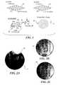
- FIG. 2Ais an exemplary low-frame rate image produced from a optical fiber scanner
- FIG. 2Bis an exemplary open loop (no controller feedback error correction) image, using a spiral 500 Hz resonant scan, with 1 Hz modulation;
- FIG. 2Cis an exemplary controlled acquired image using a controller with no feedback linearization, a spiral 500 Hz resonant scan, with 1 Hz modulation, at a 20 kHz loop rate;
- FIG. 3illustrates the equations for a non-linear model of a 2D excited optical fiber scanner
- FIG. 4is a graph of amplitude versus a reference and response for an open loop simulation
- FIG. 5shows two graphs showing a linear and a non-linear amplitude response versus frequency for an optical fiber scanner
- FIG. 6illustrates graphs of non-linear amplitude and phase response versus drive amplitude, showing the resulting distortion
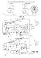
- FIG. 7Ais a functional block diagram of a control that includes a phase lock loop (PLL) and a proportional, integral, derivative (PID) amplitude control for an optical fiber scanner;
- PLLphase lock loop
- PIDproportional, integral, derivative
- FIG. 7Bis a function block diagram of a control that includes a lock-in amplifier and two PID controls;
- FIG. 8is a functional block diagram of a frequency space tracking controller with feed forward for controlling an optical fiber scanner
- FIG. 9illustrates graphs of position and tracking error versus natural frequency normalized time for a linear control model
- FIG. 10illustrates graphs of position and tracking error versus natural frequency normalized time for a non-linear control model
- FIG. 11is a functional block diagram of an error-space controller with feed forward
- FIG. 12illustrates graphs of position and tracking error versus natural frequency normalized time for a modern error-space controller with feed forward on a linear model
- FIG. 13illustrates graphs of position and tracking error versus natural frequency normalized time for a modern error-space controller with feed forward on a non-linear model
- FIG. 14is a functional block diagram of a frequency space tracking controller with feedback linearization
- FIG. 15is a functional block diagram of a modern error-space controller with feedback linearization
- FIGS. 16A and 16Bare schematic diagrams that respectively illustrate two sensors along the linear scan axis, and four sensors along the two orthogonal axes of a 2D scan pattern;
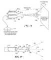
- FIG. 17is a functional block diagram of a system for remote sensing of the position of the distal tip of an optical fiber scanner
- FIG. 18is a schematic diagram illustrating a plurality of multimode optical fibers that are used to convey light to a proximal quad light sensor for determining a position of the distal tip of the resonant optical fiber;
- FIG. 19is a schematic diagram of a tapered optical fiber scanner that includes a micro-lens (i.e., an additional mass) at a distal end of the tapered optical fiber.
- a micro-lensi.e., an additional mass
- the present inventionis directed to controlling cantilevered light guides used in a many different applications. While it should be clearly understood that the present invention is not limited to controlling just an optical fiber, an initial application of the present invention for that purpose provides a disclosure of several different embodiments of exemplary controls that are used in connection with controlling the drive signal applied to cause an optical fiber to move in a desired pattern at or near its resonance. However, it is not intended that the discussion of the present invention in connection with controlling the movement of an optical fiber in any way limit its application to that type of light guide.
- a resonant optical fiber that is controlled by the present inventioncan be either tapered or non-tapered and can be driven in several scanning patterns, as appropriate for the application of the scanning optical fiber.
- the following discussionfocuses on the control of resonant scanning optical fiber that is driven in a spiral pattern, since that pattern can be implemented using a cantilevered optical fiber drive system that is substantially more compact than, for example a raster pattern, and more efficient than patterns that repeatedly cross the same portion of a surface while completing a scan of the surface.
- An initial commercial application of this controlwill likely be in connection with a SFSE that can be inserted into a patient's body, and thus, much of the following discussion is directed to controlling the SFSE.
- a SFSEhas been developed that is expected to provide the same image capabilities as current flexible fiber bundle endoscopes, but in a package no larger than 3 mm in diameter. Due to the inherent limitations of array acquisition with optical fibers used in flexible endoscopes, at bundle diameters less than 3 mm, the FOV or resolution of the optical fiber relay must be sacrificed. To achieve high resolution, wide field of view images from a smaller device, the SFSE uses a resonant optical fiber scanner 30 , as shown in FIG. 1 , to move a single light spot over a surface, and a single photodetector (not shown) to measure the intensity variation of the backscattered light from the spot on the illuminated surface.
- an intensity map of the surfacecan be made.
- the resolution of the deviceis independent of sensor size and only dependent on the spot size and sampling rate, and the FOV is determined by the scanning angle.
- opposite planar quadrants 33 a , 33 b of a piezoelectric tube actuator 32are used to vibrate a cantilevered optical fiber 34 into resonance.
- the resonant behavior of the cantilevered optical fiberproduces large deflections at a distal tip 36 of the optical fiber from small piezoelectric tube actuator movements at the base of the cantilever.
- Light emanating from the distal tipproduces a large FOV scan, such as a spiral scan pattern 40 .
- Various other space filling scan patterns besides the spiral scan patterncan be created by properly modulating the piezoelectric tube actuator drive signal, such as a raster scan and a propeller scan.
- the following discussionwill concentrate on control of the spiral scan.
- the simplest 2D scan patternsare created by using synchronized horizontal and vertical sinusoidal vibrations to produce a 1:1 Lissajous pattern.
- a circular scanresults when the horizontal and vertical resonant vibrations are of the same frequency and equal amplitude, but 90° out of phase.
- the amplitudesare modulated in a triangle pattern 42 , while the phases are kept constant. See FIG. 1 .
- the applied signalcan be described as a triangle amplitude modulated sine wave 44 , with the carrier being the resonant frequency, and the triangle modulation being applied to the amplitude of the sine wave.
- Each half cycle of the triangle modulationis a frame.
- a sinusoidal modulation for each frameis another technique that does not have a discontinuity in slope; however, the triangular pattern is an excellent choice for comparing different optical fiber scanning control methods.
- 2D space-filling resonant scans from a single actuatorare produced using an “offset frequency” x:y Lissajous pattern.
- the resonant frequencies in the two axesare required to be different.
- the resultant x:y Lissajous patternis inefficient, and typically requires custom fibers.
- a 2D patterncan be produced using a symmetric fiber with equal resonant frequencies in both axes. If the horizontal axes produce a constant amplitude sine wave, and the vertical axes produce a cosine wave of the same frequency and amplitude (but with a 90° phase difference), a circle results.
- This circular patternis a 1:1 Lissajous pattern, but this pattern does not scan over an area, i.e., it is not space filling.
- the circular scan's amplitudecan be progressively decreased and increased, yielding a spiral scan.
- This spiral scanis an amplitude modulated 1:1 Lissajous pattern.
- the horizontal vibrationcan be a triangle amplitude modulated sine wave
- the vertical vibrationcan be a triangle amplitude modulated cosine wave. If the amplitude modulation does not periodically go to zero, the spiral scan becomes a toroidal scan.
- the drive signal applied to drive a scan along the horizontal axisis a constant amplitude sine wave, and in regard to the vertical axes, the drive signal is also a sine wave of the same frequency and amplitude (with no phase difference), a 45° line results. Again, this line is not a space-filling scan. To produce, a space-filling scan, it is necessary to modulate the amplitudes of the signal for each axis.
- the horizontal vibrationcan be a cosine modulated sine wave
- the vertical vibrationcan be a sine wave modulated sine wave
- the horizontal componentis a sine wave and the vertical component is a cosine wave, a circle results. Modulating the amplitudes creates a spiral scan. If the horizontal component is a sine wave and the vertical component is also a sine wave, a skewed 45° line results. If the amplitudes are modulated, a propeller scan results. If the horizontal component is a sine wave, and the vertical component is a sine wave, but with a phase shift somewhere between 90° (a cosine wave), and 0° (a sine wave), a skewed oval results. If the amplitudes remain constant and the phases are varied, a result similar to an x:y Lissajous pattern results, which is a phase-modulated sine wave.
- amplitude modulated scansgives a resonant optical fiber the ability to produce 2D scan patterns from a single small package, compared to a 1D resonant scan plus a galvo-mirror that is typically used in conventional 2D scanners and provides a more efficient, even scan pattern than a 2D scanned x:y Lissajous scan pattern produced by a rectangular cross section optical fiber.
- the piezoelectric tube actuatorsare driven with a signal having a shape expected to produce a desired output.
- a sync pulsestarts the data acquisition for each frame of data acquired by the SFSE.
- the output scanis a scaled and distorted version of the drive waveform, with a phase shift in the carrier and the modulation waveforms.
- the phase of the carrier and modulation waves relative to the sync pulse and the modulation amplitudeare adjusted manually until a coherent image is created. Indeed, if the SFSE is run “open loop,” the frequency, phase, and amplitude of the scanner are all typically adjusted manually.
- An exemplary image 50 in FIG. 2Aillustrates the result produced by using 125 scan rings with 200 samples per ring. These frame rates are for a particular optical fiber scanner used to acquire the image in FIG. 2 A. Changes in the optical fiber scanner that is used, including the piezoelectric tube actuator and the optical fiber coupling, optical fiber type, optical fiber geometry, and resonant frequency may change the behavior of the optical scanner, but the general characteristics of a 2D resonant fiber scanning system will generally remain the same.
- an optical fiber scanner controllerIn order to increase the performance of an optical fiber scanner in producing a spiral scan, various control schemes were tested. The goal of these control schemes is to force the system to perfectly track the triangle modulated sine wave (shown in FIG. 1 ), thereby removing distortion and the toroidal scan behavior. The results of these tests are also applicable to achieving other scanning patterns, both 1D and 2D.
- An additional feature desired of an optical fiber scanner controlleris robustness in handling the inevitable variations in the scanner system due to manufacturing variability and/or environmental effects, i.e., to achieve an ideal scanning controller that ensures all light guide scanners that it controls behave the same, independent of slight differences in construction or operating conditions.
- an optical fiber scannerwas considered as a resonating base, excited cantilever. Because the optical fiber is driven through large displacements, nonlinear optical fiber dynamics are expected to dominate.
- nonlinear continuum equationsknown in the art
- approximate differential equations 62can be developed for the scanning system's behavior near resonance, as shown in FIG. 3 .
- the modelis in the same form as a 2D, cross-coupled damped oscillator with softening springs, centripetal acceleration, and a linear actuator.
- the coefficients for the differential equations shown in FIG. 3are empirically determined.
- results 66 using a nonlinear system modelshow that a spiral scan's amplitude modulation will not be linear, but will instead decay into and out of a triangle envelope, creating distortion in the image.
- An exemplary image 52 in FIG. 2Billustrates the distortion that results in an open loop scanning controller during a spiral scan. This problem is mainly due to the cantilevered optical fiber's low damping. There is also noticeable beating evident in the scan pattern after each discontinuity.
- a corresponding exemplary image 54is shown in FIG. 2C , for an optical fiber scanner controlled with the present invention.
- the optical fiberAt the modulation discontinuities, the optical fiber will be excited, creating transient disturbances at the linear natural frequency. The transient ringing will persist for many cycles because of the low damping of the optical fiber.
- a maximum amplitude 68is displaced away from its position 70 at the linear resonant frequency, as shown in an exemplary manner in FIG. 5 .
- the optical fiber responseUntil the transient dies away, the optical fiber response will therefore consist of the drive frequency and the natural frequency.
- the transient and the drive frequencywill interact with each other, creating the beating phenomena.
- the transientdoes not have sufficient time to die away. In this case, the amplitude of the drive signal may pass through zero, but the scan's amplitude does not, resulting in a toroidal scan rather than a spiral scan.
- phase and amplitude responses of the optical fiberare dependent upon the drive frequency and amplitude, as shown in FIG. 6.
- a linear amplitude relationship 74 and a linear phase relationship 76are shown as a function of a drive amplitude A d , in comparison to a nonlinear amplitude relationship 78 and a nonlinear phase relationship 80 , relative to the drive amplitude.
- the drive signalis amplitude modulated, the phase of the response changes.
- the edges of the scanare not in phase with the center, resulting in distortion, as indicated by curved radial lines 82 relative to linear radial lines 84 . This nonlinear effect also contributes to the scan's amplitude modulation decaying into and out of the triangle envelope.
- controllerswere developed that are able to produce reliable, distortion free scans. It is intended that a suitable optical fiber scanner control produce a scanned spot of light that perfectly tracks a reference waveform regardless of nonlinear effects and is robust to variability in the scanner that may arise due to manufacturing variations or due to the operating environment.
- open loop control, phase locked loops with PID amplitude control, lock-in amplifiers with PID amplitude and phase control, frequency space control with feedforward and feedback, error space control with adaptive feedforward and full state feedback, feedback linearized control, adaptive control, and robust sliding mode controlwere considered. The following discussion deals with differences in the various control techniques implemented in the present invention. It should be understood that the controllers shown in FIGS.
- phase locked loop (PLL) controllersare the most common means of control.
- a resonant scanneris typically used to produce a high-frequency constant amplitude/constant phase sinusoidal scan in the horizontal direction, and a non-resonant scanner (galvo-mirror or bi-morph) typically produces a low-frequency scan in the vertical direction, thus producing a raster scan.
- Some systemsare run open loop.
- PLLsare used to control either the frequency of the scan to produce maximum output deflection (in a scheme known as “scanner as master”), or to control the scan's phase to synchronize the scanner with an external system, e.g. an imaging system (in a scheme known as “scanner as slave”).
- the amplitude of the scanis not automatically controlled, but is manually adjusted.
- a phase comparator in a PLLis used to compare the phase of the scanner's output to the scanner's input. Based on the phase difference, a voltage controlled oscillator (VCO) in the PLL changes the scanner's input frequency until the input phase and output phase are 90° apart, i.e., when a “linear” resonant system has its maximum amplitude output. Based on the input frequency, the image acquisition or display frequencies are appropriately adjusted to maintain synchronization with the scan.
- VCOvoltage controlled oscillator
- the scanneracts as a master clock, and the image system acts as a slave; hence the name “scanner as master.”
- a phase comparator in a PLLis used to compare the phase of the scanner output to a desired reference (which governs the image acquisition or display frequencies). Based on the phase difference, the VCO in the PLL changes the scanner's input frequency until the reference phase and output phase are 90° apart. At this point, the frequency of the scanner's output will be the same as the reference frequency.
- the scanneris synchronized with the external system, which is acting as a master clock, and the scanner acts as a slave—hence the name “scanner as slave.”
- the amplitude of the scanis generally not controlled.
- the amplitude of the scanmay change due to changes in the resonant properties of system with changes in environment or aging.
- the fiber's nonlinear behavioraffects the scan pattern when the desired scan amplitude is changed. For instance, if the resonant optical fiber input amplitude is halved, its (horizontal) output scan amplitude may not decrease by half. If the other (vertical) scanner amplitude is halved, then the scan's horizontal/vertical aspect ratio will change, resulting in scan distortion. (The decrease in input amplitude will also be accompanied by a phase shift in the output, but the PLL controller, for the scanner as slave approach, will resynchronize the system.)
- the scan patternis not controlled; instead, only the phase is controlled.
- the scan from a resonant optical fiber scanneris nearly sinusoidal due to the narrow frequency range of resonant amplification, the nonlinear behavior of the optical fiber may introduce additional vibration frequencies (harmonics). These harmonics may interfere with the performance of the PLL or distort the scan.
- the scanner as master schemeassumes that the maximum amplitude output occurs when the input phase and the output phase of the resonant fiber are 90° apart, which is not true for all resonant systems, especially those with damping and significant nonlinear behavior. This assumption also does not account for phase shifts (time delays) introduced by the actuator used to drive the optical fiber.
- PLL controllers of the prior artare only useful for constant amplitude sinusoidal scans at a fixed phase. Amplitude is generally not controlled in such prior art scanner controls, but instead, is manually adjusted.
- a PLLwas adapted to address the problem of tracking a modulated amplitude sine wave.
- a standard PLL module 92is employed to control the phase
- a PID module 94is employed to control the amplitude, as shown for a control 90 in FIG. 7 A.
- a desired scan pattern 96 from a waveform reference 99 , and the position signal output from a sensor 98are input to a phase detector 100 of the PLL.
- the output of the phase detectorpasses through a low pass filter 104 , leaving only a DC component related to the phase difference that is applied to a VCO 110 .
- the low pass filter's outputcontrols the frequency of the VCO.
- the frequency of the VCOshould be the same as the reference, and the phase between the reference and the output should be 90°.
- the amplitude of the VCOis multiplied (or amplified) by the amplitude control scheme of control 90 .
- the amplitude control schemeincludes a synchronous amplitude demodulator 102 , which is used as an amplitude detector, and a PID controller.
- An amplitude demodulatoris a standard circuit used in AM radio communications. In radio communications, the amplitude of a high frequency carrier wave is slowly varied (modulated) to encode audio information, which is then transmitted. The receiver is tuned to the high frequency carrier wave, then uses an amplitude demodulator to determine the (slowly varying) amplitude to decode the audio information.
- the carrier wavecorresponds to the resonant vibrations of the optical fiber.
- the amplitude of the fiberis determined by the amplitude demodulator as a function of a signal indicative of a sensed position of the moving portion of the optical fiber.
- the amplitudeis then used in a standard PID feedback controller to produce a commanded input amplitude to actuator for the optical fiber.
- the commanded input amplitudeis proportional to the error between the desired amplitude and the sensed amplitude (P), proportional to the integral (I) (sum over time) of that error, and proportional to the derivative (D) or change with respect to time of that error—hence, the name “PID controller.”
- Amplitude demodulator 102takes the position measurement from a sensor and produces the modulation amplitude as an output.
- the amplitude of the scan from the amplitude demodulatoris compared by a comparator 108 to a reference triangle modulation wave from an amplitude reference 106 , and any difference (error) between the two amplitudes is driven to zero by PID module 94 , which has its output coupled to a multiplier 111 .
- the output of VCO 110is also applied to multiplier 111 and its output is used to drive resonant optical fiber scanner 30 .
- FIG. 7Billustrates another control 90 ′ that does not include PLL controller 92 for controlling phase, but instead uses another PID controller 95 .
- a phase ( ⁇ ) reference 97provides a reference phase input to PID controller 95 , which is compared to a phase output signal from a dual-phase lock-in amplifier 105 .
- a dual-phase lock-in amplifieris a standard circuit used in scientific measurements and can accurately and concurrently detect the amplitude and phase of a desired frequency from input signals even in the presence of large amounts of noise and other corrupting frequencies.
- PID 95produces a phase output signal that is applied a function generator 109 .
- Dual-phase lock-in amplifier 105has its inputs coupled to receive signals from sensor 98 and from reference waveform source 99 .
- An amplitude output signal from dual-phase lock-in amplifier 105is coupled to PID 94 , which also has an input connected to the reference triangle modulation wave from amplitude reference 106 .
- the output from PID 94is coupled to function generator 109 .
- Either control 90 or control 90 ′can be used with a 2D actuator to remove whirl in a 1D scan by an optical fiber.
- the horizontal scanis controlled to achieve the desired amplitude and phase.
- the optical fiber's nonlinear behaviormay cause an undesired response in the vertical direction (whirl).
- the amplitude controller portion of the control(PID 94 of control 90 or dual-phase lock-in amplifier 105 and PID 94 of control 90 ′) is used with the scanner's vertical actuators and is supplied a commanded amplitude of zero. With the PID controller's command proportional to the integral of the error, the control can provide a drive input to the actuators with an appropriate phase and amplitude to cancel the whirl.
- PLL and/or PID controller modulesin controls 90 and 90 ′ are that they do not need a dynamic model of the system and its parameters.
- Selection of the low pass filter characteristics of low pass filter 104determines the dynamics of PLL 92 .
- Selection of the gain used by control 90determines the dynamics of the PID module. Basically, the gain is controlled by a user to achieve a desired response. Care must be taken in setting the coefficients used by the PID and choosing the low pass filter characteristics of the PLL.
- the optical fiber's phase and amplitude responsesare interrelated. A change in one results in a disturbance and long lasting transient in the other. Because the amplitude and phase are controlled with one drive signal in control 90 , the two controllers (PLL and PID) can fight each other.
- Trackingis defined as the application of a calculated input to force the position of the moving portion of an optical fiber to follow a known desired reference. Tracking the optical fiber position is preferable to controlling the amplitude and the phase of wave form that drives the optical fiber. With perfect tracking, the desired amplitude, phase, frequency, and scan pattern are all simultaneously met.
- a controller 120shown in FIG. 8 , computes an input to resonant optical fiber scanner 30 required to achieve a desired output, based upon a system (plant) dynamic model.
- the dynamic model used in this controllerdescribes how the fiber output is related to the frequency and amplitude of the actuator input and to system parameters such as system damping, actuator strength, and optical fiber natural frequency.
- a desired outpute.g., a constant amplitude, a constant phase sinusoid, or an amplitude modulated sinusoid.
- This use of a modelis called “plant-inversion,” feedforward, or back-propagation, and does not require feedback of the optical fiber position.
- a filtered feedback of the optical fiber position(of the tip or other moving portion of the optical fiber that affects the tip position) stabilizes the system and increases the rejection rate of disturbances in the system.
- An error feedback module 122 in control 120provides stabilization of the overall system and error dynamics. With a proper choice of a filter for the feedback signal, the error will result in asymptotic tracking for a linear system.
- control 120needs a desired position, velocity, and acceleration, which are based upon a reference signal set produced by combining desired signal 96 and a triangle waveform amplitude 124 with a multiplier 126 which provides position, velocity, and acceleration inputs to a model inversion (feedforward) module 128 .
- the feedforward output signalis added to the feedback signal by an adder 130 , producing the output signal used to drive resonant optical fiber scanner 30 .
- control 120To perform the error feedback, control 120 only needs the position of the distal tip of the optical fiber, which is provided from sensor 98 . The position of the optical fiber is compared to the reference position by comparator 108 , producing an error signal e.
- the feedback moduleprocesses the error signal, producing the signal supplied to adder 130 .
- control 120is able to asymptotically track a triangle modulated sine wave in both the horizontal and vertical axes, except at discontinuities. At the discontinuities, there is a jump in the error, then the response exponentially decays to zero in the steady state, as shown in FIG. 9 .
- the steady state erroris an exponentially ramped sinusoid, as indicated in FIG. 10 .
- the errordoesn't appear to jump in magnitude.
- the errorcan be reduced by increasing the amount of feedback, but doing so tends to destabilize the system.
- the tracking controlleris also sensitive to model inaccuracies, including model parameter variations and nonlinear effects, because the model is used to calculate the necessary input for the desired output.
- error-space controller 140Another linear controller used for asymptotic tracking and robust to parameter variations, is an error-space controller 140 , shown in FIG. 11 .
- This controlleremploys equations for the reference waveform and equations for the scanner's dynamics, and derives the system's error dynamics. The problem of tracking is reformulated into driving the error to zero.
- a sensor 142provides signals indicative of the position (and optionally velocity) of the distal tip of the resonant optical fiber. If a velocity measurement is not available, an estimate can be made from a low pass filtered derivative of the position measurement, or by a Kalman filter provided with the position measurement and the actuator input. The Kalman filter provides a position estimate and a velocity estimate from noisy position (and optionally velocity) measurements.
- the sensor position signal or the Kalman filter's position estimateis also input to comparator 108 and compared to the reference position, producing the error signal, e.
- the error-space controlleruses the position error in a feedforward module 144 to adjust the input model for feed forward tracking and robustness for modeling inaccuracies. It also uses a full state feedback module 146 , which receives the position and velocity estimate signals from the Kalman filter to stabilize the system and remove disturbances. For full stale feedback, the estimated optical fiber tip position and velocity must be known, and their values are employed to produce a combined feedback signal provided at an output of an adder 148 .
- the output of adder 148is combined with the output of the feedforward module by an adder 150 , producing the input signal used to drive the resonant optical fiber scanner. Simulations show that such a control asymptotically tracks the ramped sinusoid for a linear system, but that error jumps at the peak discontinuity and exponentially decays to zero afterwards, as shown in FIG. 12 .
- the erroris still a ramped sinusoid, but much smaller than the frequency space controller results on a nonlinear system.
- the errorjumps, but dies away exponentially, returning to the low level ramped sinusoid as shown in FIG. 13 .
- Most of the steady state erroris due to phase error, as evidenced by a close examination of the plots shown in these Figures, from which it will be evident that the reference and error plots are similar.
- u _ xu x + ⁇ ⁇ ⁇ x ⁇ ( x 2 + y 2 ) + ⁇ 2 ⁇ x ⁇ ( x . 2 + y . 2 )
- u _ yu y + ⁇ ⁇ ⁇ y ⁇ ( x 2 + y 2 ) + ⁇ 2 ⁇ y ⁇ ( x . 2 + y . 2 )
- linear controllerscan be applied to nonlinear systems and can achieve results predicted by the linear model used by the linear controller—asymptotic tracking.
- control 160The functional components for tracking control with feedback linearization and modern error-space control with feedback linearization are respectively shown in regard to a control 160 and a control 190 , which are respectively shown in FIGS. 14 and 15 , discussed below.
- the responses of control 160are not shown, but are identical to the linear model results shown in the Figures for the respective linear controller sections.
- frequency space tracking controls 168 and 170 for the x and y axesuse feedback linearization modules 164 and 166 to cancel out the nonlinear effects with respect to each axis.
- Each of frequency space tracking controls 168 and 170includes the controller shown in FIG. 8 , i.e., includes the model inversion (feedforward) module, and the feedback module, as well as the other components of controller 120 and is used for controlling the drive signal for one of two orthogonal axes, x and y. As shown in FIG.
- desired periodic waveform patterns 96 and 172are combined with triangle waveform amplitude 124 in multipliers 174 and 176 to provide x and y axes reference signals that are input to tracking controls 168 and 170 , respectively.
- Feedback of the x and y positions of the distal tip of the optical fiberis supplied from a position sensor 162 to controls 168 and 170 and to feedback linearization modules 164 and 166 .
- the output signals from the tracking controls and from the feedback linearization modulesare added by adders 178 and 180 for the x and y axes, respectively, producing output signals that drive the resonant optical fiber scanner relative to both the x and y axes.
- feedforwardis used to compute the input to give the desired output
- the feedback signalis employed to stabilize the system and remove disturbances
- feedback linearizationis added to remove nonlinear behavior.
- Control 160asymptotically tracks the triangle amplitude modulated sine wave, except at discontinuities. After a discontinuity, there is a jump in error that exponentially decays to zero.
- Tracking controls 168 and 170require the reference position, velocity, and acceleration (supplied from multipliers 174 and 176 ), and the output from position sensor 162 . The tracking controls are sensitive to model inaccuracies, which may lead to steady state errors.
- a control 190 in FIG. 15uses a number of the same components as control 160 , but includes error-space controls 194 and 196 .
- Each error-space control 194 and 196includes the components of controller 140 ( FIG. 11 ) and is used to control the drive signal applied to a different one of the x and y axes of the optical scanner.
- a position and velocity sensor 192provides position and velocity for both the x and y axes (or velocity can be computed as the first derivative of the position with respect to time for each axis or estimated from a Kalman filter).
- Feedback linearization modules 164 and 166are employed in this controller to cancel out nonlinear effects, full-state feedback is employed to stabilize the system and remove disturbances, and adaptive feedforward uses an input model for tracking and robustness.
- Control 190is able to asymptotically track the triangle amplitude modulated sine wave except where there is a discontinuity. After a discontinuity, there is a jump in error, which exponentially decays to zero.
- the error-space controlrequires the reference position (supplied from multipliers 174 and 176 ), and the tip position and the velocity of the tip, and is insensitive to inaccuracies in the parameters of the linear model.
- sensorsare used to determine frequency, position, and/or functional equivalents of the optical fiber motion in order to determine the optical fiber tip position (also, velocity of the distal tip) over time.
- sensors on the surface of the optical fiber scannercan be used to measure the bending of the optical fiber along the axis on which the sensor is placed.
- sensors 208 and 210are shown mounted on a base 202 of a tapered optical fiber 200 , for both linear optical fiber scanning and 2D optical fiber scanning, respectively.
- FIG. 16A and 16Bsensors 208 and 210 are shown mounted on a base 202 of a tapered optical fiber 200 , for both linear optical fiber scanning and 2D optical fiber scanning, respectively.
- two sensors 212are mounted on opposite sides of the optical fiber, at positions generally orthogonal to those of sensors 208 and 210 .
- a cantilevered tapered portion 204 of the optical fiberhas a distal end 206 that is resonantly driven as shown in the Figures.
- the sensorscan measure optical fiber bending with one of several mechanisms, such as electromechanical and optical.
- An electromechanical sensor made from a piezoelectric film or micro-strain gaugecan measure compressive and tensile forces as the sensor bends with the optical fiber.
- An optical sensor made from a photodiode materialcan measure increases in light leakage as the optical fiber bending increases transverse to the longitudinal axis of the optical fiber (decreasing its radius of curvature). In FIG.
- the distal tipswings at a near resonant amplitude from an extreme displacement in one direction, as shown by the solid lines, to an extreme displacement in an opposite direction as shown by the dash lines.
- the arc of the distal tip of the waveguideis proportional to the optical FOV for the linear scan.
- Sensors 208 and 210which are used for monitoring the movement of the distal tip, are shown overlying piezoelectric bimorph actuators 209 that drive the optical fiber to move in response to an applied drive signal, but it will be appreciated that the sensors are mounted separately from the actuators, and can be mounted at a variety of locations on the optical fiber, adjacent to the distal end.
- the sensorsare coupled to an external control (not shown), such as those discussed above.
- Dual sensors 208 / 210 , and dual sensors 212which are provided along each of two orthogonal axes of bending, as shown in FIG. 16B , increase the signal-to-noise ratio of the measurement and are preferred.
- Alternative methodscan employ sensing apparatus and techniques conventionally used for determining the relative position of scanned probes, such as near-field scanning optical microscopy, shear-force microscopy, and atomic force microscopy.
- a new methodhas been developed for remote sensing of the displacement of the distal tip of an optical fiber or waveguide, employing only optical techniques. This method takes advantage of the strain birefringence inherent in most optical fibers. By doing so, the need for integrated displacement-sensing hardware is eliminated, which keeps the size of the resonant scanning optical fiber relatively compact. In applications where the sensor or optical fiber scanner needs to be disposable, such as micro-endoscopes employing optical fiber scanning technology, the overall cost and complexity of the design is also considerably reduced.
- This technique of measuring repolarized lightis advantageous over bending-loss measurement schemes, because it yields a signal only when the optical fiber is stressed, thus improving the signal-to-noise ratio of the measurement. Bending-loss only schemes produce a small reduction in a large signal and suffer from poor signal-to-noise ratio.
- the simplest remote-sensing hardware configurationincludes a single photosensor and a polarizing filter.
- the axis of the polarizing filteris positioned at 90° to the initial polarization vector of the light in the optical fiber (before fiber bending), so that only repolarized light is transmitted through the polarizing filter to the photosensor.
- a more complex configuration with two photosensorsyields a normalized measurement of light intensity and enables depolarization measurements to be made. Since this method is also capable of measurement of polarization vector rotation through a 90° range, repolarization can be more directly measured than in the single photosensor configuration, where repolarization is inferred from transmitted intensity.
- FIG. 17shows one exemplary configuration of a displacement sensor in which displacement can be measured using polarized light.
- the stress acting on the optical fiberchanges the orientation or repolarizes the polarization vector of polarized light that is traveling through the optical fiber.
- the sensor in FIG. 17detects this repolarization to determine the position of an optical fiber as it moves and bends.
- a laser diode 250(or other suitable light source) produces polarized light having a first wavelength
- a laser diode 258produces light having a second wavelength that is different than the first and is used for scanning by an optical scanner 256 .
- the two light beamsare combined by an optical mixer/splitter 254 and travel into the moving portion of optical scanner 256 .
- Repolarized light caused by the bending of this moving portion of scanning optical fiber 256travels back through optical mixer/splitter 254 and is split, traveling back into polarization beam splitter 252 .
- Polarization filter 264has its polarization axis oriented to pass light having a polarization vector that is orthogonal to the original polarization vector of the light from laser diode 250 .
- a photosensor 266is disposed to monitor the intensity of the light passing through polarizing filter 264 , which is indicative of the deflection of the optical scanning fiber. This sensor can be simplified by using light of the same wavelength for both scanning and for detecting the deflection of the optical scanner.
- a major application for this remote-sensing systemis for use with a control of an optical fiber scanner, such as the controls discussed above.
- This sensing methodhas a high bandwidth and can be implemented in real-time (i.e., with extremely small latency times ⁇ 10 microseconds), which allows mapping of the optical fiber tip position during scanning.
- a remapping stepcan be used to remap the intensity data for image display or acquisition to minimize distortions.
- the above-described schemeonly measures displacement and not absolute position of the optical fiber.
- FIG. 18Yet another sensor scheme for monitoring the position of distal tip 206 of a resonant scanning optical fiber is illustrated in FIG. 18 .
- four sensor optical fibers(multimode) are arrayed at orthogonally opposed positions around base 202 of the optical fiber whose moving distal tip is being monitored. Only sensor optical fibers 214 a , 214 b , and 214 c are visible in FIG. 18 , since the fourth sensor optical fiber is disposed opposite sensor optical fiber 214 b and is behind the base and not visible in the Figure.
- a partially reflective window 214is provided to reflect light emitted from distal tip 206 back toward the sensor optical fibers.
- the light reflected back from partially reflective window 214passes through the sensor optical fibers and is conveyed proximally, to illuminate a quad photodetector 216 (or other 2D detector or group of detectors).
- the quad photodetectorresponds to the light traveling through sensor optical fibers, producing a signal that is indicative of the position of distal tip 206 .
- This signalcan be processed to determine a first derivative of position with respect to time, to determine a velocity for the distal tip.
- a tapered portion 238 of an optical fiber 236is attached to the distal end of a piezoelectric actuator 232 , close to the proximal end of the tapered portion.
- the exact point of attachment, mechanical properties of the waveguide, and taper geometrydetermine the resonance frequencies of the optical fiber.
- the actuation, amplitude, and frequency of the piezoelectric actuatordetermine the amplitudes of optical fiber displacement and deflection of a distal tip 240 , its frequency, and the optical scanning pattern it describes.
- an optical fiber cantileveris extended from about 1 mm to about 4 mm out from its point of attachment at the end of the piezoelectric bimorph to achieve high FOV scanning frequencies, i.e., greater than 18 kHz.
- both micro-fabricated optical fiber 236 and the actuatorare cantilevered in a fixed-free boundary condition.
- a protective tube 234surrounds the optical fiber and the actuator.
- piezoelectric electrodes (not shown) on the actuatorare connected by fine wires (also not shown) to one of the controls discussed above, which drives the optical fiber with a controlled sinusoidal waveform of variable voltage (amplitude) at a desired frequency (e.g., adjustable from about 1 kHz to about 100 kHz).
- Separate imaging and/or scan lenses 242 and 244can be disposed adjacent to the tip of the micro-fabricated fiber scanner to generate focused linear and 2D scan patterns onto a screen. Furthermore, a micro-lens 248 is fabricated onto distal tip 240 of optical fiber 236 , as shown in FIG. 19 , to focus light 246 emitted by the scanning optical fiber.
- the micro-lensrepresents a small additional mass that is readily accounted for in any of the controls discussed above.
Landscapes
- Health & Medical Sciences (AREA)
- Life Sciences & Earth Sciences (AREA)
- Physics & Mathematics (AREA)
- Optics & Photonics (AREA)
- Surgery (AREA)
- Biomedical Technology (AREA)
- Medical Informatics (AREA)
- Radiology & Medical Imaging (AREA)
- Nuclear Medicine, Radiotherapy & Molecular Imaging (AREA)
- Engineering & Computer Science (AREA)
- Biophysics (AREA)
- Heart & Thoracic Surgery (AREA)
- Pathology (AREA)
- Molecular Biology (AREA)
- Animal Behavior & Ethology (AREA)
- General Health & Medical Sciences (AREA)
- Public Health (AREA)
- Veterinary Medicine (AREA)
- General Physics & Mathematics (AREA)
- Mechanical Optical Scanning Systems (AREA)
Abstract
Description
{umlaut over (x)}+b{dot over (x)}+x+εx(x2+y2)+εx({dot over (x)}2+{dot over (y)}2)=Cux
ÿ+b{dot over (y)}+y+εy(x2+y2)+y({dot over (x)}2+{dot over (y)}2)=Cy
Adding a new control function to cancel nonlinearity results in:
The system then acts like a linear system:
{umlaut over (x)}+b{dot over (x)}+x=Cūx
ÿ+b{dot over (x)}+y=Cūy,
Claims (50)
Priority Applications (1)
| Application Number | Priority Date | Filing Date | Title |
|---|---|---|---|
| US10/305,914US6845190B1 (en) | 2000-11-27 | 2002-11-26 | Control of an optical fiber scanner |
Applications Claiming Priority (4)
| Application Number | Priority Date | Filing Date | Title |
|---|---|---|---|
| US25344500P | 2000-11-27 | 2000-11-27 | |
| US33342101P | 2001-11-26 | 2001-11-26 | |
| US09/994,377US6856712B2 (en) | 2000-11-27 | 2001-11-26 | Micro-fabricated optical waveguide for use in scanning fiber displays and scanned fiber image acquisition |
| US10/305,914US6845190B1 (en) | 2000-11-27 | 2002-11-26 | Control of an optical fiber scanner |
Related Parent Applications (1)
| Application Number | Title | Priority Date | Filing Date |
|---|---|---|---|
| US09/994,377Continuation-In-PartUS6856712B2 (en) | 2000-11-27 | 2001-11-26 | Micro-fabricated optical waveguide for use in scanning fiber displays and scanned fiber image acquisition |
Publications (1)
| Publication Number | Publication Date |
|---|---|
| US6845190B1true US6845190B1 (en) | 2005-01-18 |
Family
ID=33568505
Family Applications (1)
| Application Number | Title | Priority Date | Filing Date |
|---|---|---|---|
| US10/305,914Expired - LifetimeUS6845190B1 (en) | 2000-11-27 | 2002-11-26 | Control of an optical fiber scanner |
Country Status (1)
| Country | Link |
|---|---|
| US (1) | US6845190B1 (en) |
Cited By (228)
| Publication number | Priority date | Publication date | Assignee | Title |
|---|---|---|---|---|
| US20020096649A1 (en)* | 2000-12-14 | 2002-07-25 | Gerhard Hahn | Process and device for ceramising the base glass of glass ceramics |
| US20030160161A1 (en)* | 2002-02-28 | 2003-08-28 | Moritex Corporation | Optical scanning apparatus |
| US20040151466A1 (en)* | 2003-01-24 | 2004-08-05 | Janet Crossman-Bosworth | Optical beam scanning system for compact image display or image acquisition |
| US20040204776A1 (en)* | 2003-04-11 | 2004-10-14 | International Business Machines Corporation | Servo system for a two-dimensional micro-electromechanical system (MEMS)-based scanner and method therefor |
| US20050007477A1 (en)* | 2003-05-02 | 2005-01-13 | Yavuz Ahiska | Correction of optical distortion by image processing |
| US20050020926A1 (en)* | 2003-06-23 | 2005-01-27 | Wiklof Christopher A. | Scanning endoscope |
| US20050018264A1 (en)* | 2003-07-21 | 2005-01-27 | Beneficial Imaging Corporation | Method and apparatus for scanning an optical beam using an optical conduit |
| US20050066713A1 (en)* | 2003-09-30 | 2005-03-31 | Iowa State University Research Foundation, Inc. | Method to transiently detect samples in atomic force microscopes |
| US20050201430A1 (en)* | 2002-01-31 | 2005-09-15 | Toshiki Koshimae | Laser oscillator |
| US20060018596A1 (en)* | 2004-07-22 | 2006-01-26 | Ondine International Ltd. | Fiber optic probe tip |
| US20060072843A1 (en)* | 2004-10-01 | 2006-04-06 | University Of Washington | Remapping methods to reduce distortions in images |
| US20060072874A1 (en)* | 2004-10-01 | 2006-04-06 | University Of Washington | Configuration memory for a scanning beam device |
| WO2006041452A1 (en)* | 2004-10-01 | 2006-04-20 | University Of Washington | Remapping methods to reduce distortions in images |
| US20060111739A1 (en)* | 2002-09-03 | 2006-05-25 | Urs Staufer | Device for stabilising and/or positioning a medical tool in a body cavity |
| US20060138238A1 (en)* | 2004-12-23 | 2006-06-29 | University Of Washington | Methods of driving a scanning beam device to achieve high frame rates |
| US20060139948A1 (en)* | 2003-02-10 | 2006-06-29 | Huck Hubertina Petronella M | Display illumination system and manufacturing method thereof |
| US20060149127A1 (en)* | 2004-12-30 | 2006-07-06 | Seddiqui Fred R | Disposable multi-lumen catheter with reusable stylet |
| US20060226231A1 (en)* | 2005-03-29 | 2006-10-12 | University Of Washington | Methods and systems for creating sequential color images |
| US20060254346A1 (en)* | 2003-09-30 | 2006-11-16 | Iowa State University Research Foundation, Inc. | Method to transiently detect sample features using cantilevers |
| US20070015989A1 (en)* | 2005-07-01 | 2007-01-18 | Avantis Medical Systems, Inc. | Endoscope Image Recognition System and Method |
| US20070019906A1 (en)* | 2005-07-21 | 2007-01-25 | University Of Washington Uw Tech Transfer - Invention Licensing | Methods and systems for counterbalancing a scanning beam device |
| US20070031081A1 (en)* | 2005-08-05 | 2007-02-08 | George Benedict | Methods and devices for moving optical beams |
| US7189961B2 (en) | 2005-02-23 | 2007-03-13 | University Of Washington | Scanning beam device with detector assembly |
| US20070142711A1 (en)* | 2005-12-13 | 2007-06-21 | Lex Bayer | Detachable Imaging Device, Endoscope Having A Detachable Imaging Device, And Method of Configuring Such An Endoscope |
| US20070177008A1 (en)* | 2005-01-05 | 2007-08-02 | Avantis Medical, Inc. | Endoscope with an imaging catheter assembly and method of configuring an endoscope |
| US20070185384A1 (en)* | 2006-01-23 | 2007-08-09 | Avantis Medical Systems, Inc. | Endoscope |
| US20070244354A1 (en)* | 2006-04-18 | 2007-10-18 | Avantis Medical Systems, Inc. | Vibratory Device, Endoscope Having Such A Device, Method For Configuring An Endoscope, And Method Of Reducing Looping Of An Endoscope. |
| US20070270642A1 (en)* | 2006-05-19 | 2007-11-22 | Avantis Medical Systems, Inc. | System and method for producing and improving images |
| US20070293720A1 (en)* | 2005-01-05 | 2007-12-20 | Avantis Medical Systems, Inc. | Endoscope assembly and method of viewing an area inside a cavity |
| US7312879B2 (en) | 2005-08-23 | 2007-12-25 | University Of Washington | Distance determination in a scanned beam image capture device |
| US20070299309A1 (en)* | 2005-02-28 | 2007-12-27 | University Of Washington | Monitoring disposition of tethered capsule endoscope in esophagus |
| US7313948B2 (en) | 2003-09-30 | 2008-01-01 | Iowa State University Research Foundation | Real time detection of loss of cantilever sensing loss |
| US20080001850A1 (en)* | 2006-06-06 | 2008-01-03 | Mark Champion | Beam scanner with reduced phase error |
| US20080021274A1 (en)* | 2005-01-05 | 2008-01-24 | Avantis Medical Systems, Inc. | Endoscopic medical device with locking mechanism and method |
| US20080033450A1 (en)* | 2006-08-04 | 2008-02-07 | Lex Bayer | Surgical Port With Embedded Imaging Device |
| US20080058597A1 (en)* | 2006-09-06 | 2008-03-06 | Innurvation Llc | Imaging and Locating Systems and Methods for a Swallowable Sensor Device |
| US20080058629A1 (en)* | 2006-08-21 | 2008-03-06 | University Of Washington | Optical fiber scope with both non-resonant illumination and resonant collection/imaging for multiple modes of operation |
| EP1901107A1 (en)* | 2006-09-14 | 2008-03-19 | Optiscan Pty Ltd | Optical fibre scanning apparatus |
| US20080073517A1 (en)* | 2006-09-13 | 2008-03-27 | Charles David Melville | Temperature adjustment in scanning beam devices |
| US20080106777A1 (en)* | 2006-11-03 | 2008-05-08 | Weir Michael P | Resonant fourier scanning |
| US20080114224A1 (en)* | 2006-09-06 | 2008-05-15 | Innuravation Llc | Methods and systems for acoustic data transmission |
| US20080130108A1 (en)* | 2005-01-05 | 2008-06-05 | Avantis Medical Systems, Inc. | Endoscope assembly with a polarizing filter |
| US20080132834A1 (en)* | 2006-12-04 | 2008-06-05 | University Of Washington | Flexible endoscope tip bending mechanism using optical fibers as tension members |
| US20080146871A1 (en)* | 2006-09-06 | 2008-06-19 | Innurvation, Inc. | Ingestible Low Power Sensor Device and System for Communicating with Same |
| US20080146898A1 (en)* | 2006-12-19 | 2008-06-19 | Ethicon Endo-Surgery, Inc. | Spectral windows for surgical treatment through intervening fluids |
| US20080144998A1 (en)* | 2006-12-15 | 2008-06-19 | University Of Washington | Attaching optical fibers to actuator tubes with beads acting as spacers and adhesives |
| US20080151343A1 (en)* | 2006-12-22 | 2008-06-26 | Ethicon Endo-Surgery, Inc. | Apparatus including a scanned beam imager having an optical dome |
| US20080154248A1 (en)* | 2006-12-22 | 2008-06-26 | Ethicon Endo-Surgery, Inc. | Apparatus and method for medically treating a tattoo |
| US20080165360A1 (en)* | 2007-01-10 | 2008-07-10 | University Of Washington | Scanning beam device calibration |
| US20080167546A1 (en)* | 2007-01-09 | 2008-07-10 | Ethicon Endo-Surgery, Inc. | Methods for imaging the anatomy with an anatomically secured scanner assembly |
| US20080173803A1 (en)* | 2007-01-18 | 2008-07-24 | Ethicon Endo-Surgery, Inc. | Scanning beam imaging with adjustable detector sensitivity or gain |
| US20080221388A1 (en)* | 2007-03-09 | 2008-09-11 | University Of Washington | Side viewing optical fiber endoscope |
| US20080226029A1 (en)* | 2007-03-12 | 2008-09-18 | Weir Michael P | Medical device including scanned beam unit for imaging and therapy |
| US20080243030A1 (en)* | 2007-04-02 | 2008-10-02 | University Of Washington | Multifunction cannula tools |
| US20080249369A1 (en)* | 2007-04-05 | 2008-10-09 | University Of Washington | Compact scanning fiber device |
| US20080253686A1 (en)* | 2007-04-10 | 2008-10-16 | Avantis Medical Systems, Inc. | Method and Device for Examining or Imaging an Interior Surface of a Cavity |
| US20080265178A1 (en)* | 2007-04-26 | 2008-10-30 | University Of Washington | Driving scanning fiber devices with variable frequency drive signals |
| US20080281159A1 (en)* | 2007-05-08 | 2008-11-13 | University Of Washington | Coordinating image acquisition among multiple endoscopes |
| US20080281207A1 (en)* | 2007-05-08 | 2008-11-13 | University Of Washington | Image acquisition through filtering in multiple endoscope systems |
| US20080291597A1 (en)* | 2007-05-22 | 2008-11-27 | Seibel Eric J | Scanning beam device having different image acquisition modes |
| US20090002794A1 (en)* | 2007-06-29 | 2009-01-01 | Ethicon Endo-Surgery, Inc. | Receiver aperture broadening for scanned beam imaging |
| US20090015695A1 (en)* | 2007-07-13 | 2009-01-15 | Ethicon Endo-Surgery, Inc. | Sbi motion artifact removal apparatus and method |
| US20090024191A1 (en)* | 2006-03-03 | 2009-01-22 | University Of Washington | Multi-cladding optical fiber scanner |
| US20090021818A1 (en)* | 2007-07-20 | 2009-01-22 | Ethicon Endo-Surgery, Inc. | Medical scanning assembly with variable image capture and display |
| WO2009014525A1 (en)* | 2007-07-25 | 2009-01-29 | University Of Washington | Actuating an optical fiber with a piezoelectric actuator and detecting voltages generated by the piezoelectric actuator |
| US20090036734A1 (en)* | 2007-07-31 | 2009-02-05 | Ethicon Endo-Surgery, Inc. | Devices and methods for introducing a scanning beam unit into the anatomy |
| US20090062935A1 (en)* | 2007-08-29 | 2009-03-05 | Abramovitch Daniel Y | Automatic Generation Of PID Parameters For An Atomic Force Microscope |
| WO2009045199A1 (en)* | 2007-10-04 | 2009-04-09 | University Of Washington | Reducing distortion in scanning fiber devices |
| US20090092196A1 (en)* | 2007-10-05 | 2009-04-09 | Innurvation, Inc. | Data Transmission Via Multi-Path Channels Using Orthogonal Multi-Frequency Signals With Differential Phase Shift Keying Modulation |
| US20090103882A1 (en)* | 2006-12-15 | 2009-04-23 | Charles David Melville | Attaching optical fibers to actuator tubes with beads acting as spacers and adhesives |
| US20090137893A1 (en)* | 2007-11-27 | 2009-05-28 | University Of Washington | Adding imaging capability to distal tips of medical tools, catheters, and conduits |
| US20090141997A1 (en)* | 2007-11-30 | 2009-06-04 | University Of Washington | Reducing noise in images acquired with a scanning beam device |
| US20090201034A1 (en)* | 2008-02-11 | 2009-08-13 | Qualcomm Mems Technologies, Inc. | Methods for measurement and characterization of interferometric modulators |
| US20090201242A1 (en)* | 2008-02-11 | 2009-08-13 | Qualcomm Mems Technologies, Inc. | Sensing to determine pixel state in a passively addressed display array |
| US20090204350A1 (en)* | 2008-02-11 | 2009-08-13 | Qualcomms Technologies, Inc, | Methods for measurement and characterization of interferometric modulators |
| US20090201282A1 (en)* | 2008-02-11 | 2009-08-13 | Qualcomm Mems Technologies, Inc | Methods of tuning interferometric modulator displays |
| US20090207159A1 (en)* | 2008-02-11 | 2009-08-20 | Qualcomm Mems Technologies, Inc. | Method and apparatus for sensing, measurement or characterization of display elements integrated with the display drive scheme, and system and applications using the same |
| US20090213211A1 (en)* | 2007-10-11 | 2009-08-27 | Avantis Medical Systems, Inc. | Method and Device for Reducing the Fixed Pattern Noise of a Digital Image |
| EP2096688A2 (en) | 2008-02-29 | 2009-09-02 | The University of Washington | Piezoelectric substrate, fabrication and related methods |
| US20090231419A1 (en)* | 2007-02-06 | 2009-09-17 | Avantis Medical Systems, Inc. | Endoscope Assembly and Method of Performing a Medical Procedure |
| US20090235396A1 (en)* | 2000-06-19 | 2009-09-17 | University Of Washington | Integrated optical scanning image acquisition and display |
| US20090245599A1 (en)* | 2008-03-27 | 2009-10-01 | Ethicon Endo-Surgery, Inc. | Method for creating a pixel image from sampled data of a scanned beam imager |
| US20090259420A1 (en)* | 2008-04-11 | 2009-10-15 | Apple Inc. | Adaptive surface concentration battery charging |
| US20090270724A1 (en)* | 2008-04-25 | 2009-10-29 | Ethicon Endo-Surgery, Inc. | Scanned beam device and method using same which measures the reflectance of patient tissue |
| US20090323076A1 (en)* | 2007-05-03 | 2009-12-31 | University Of Washington | High resolution optical coherence tomography based imaging for intraluminal and interstitial use implemented with a reduced form factor |
| US20100002071A1 (en)* | 2004-04-30 | 2010-01-07 | Grandeye Ltd. | Multiple View and Multiple Object Processing in Wide-Angle Video Camera |
| US20100060966A1 (en)* | 2008-09-10 | 2010-03-11 | Samsung Electronics Co., Ltd. | Actuator using piezoelectric element and method of driving the same |
| US20100099951A1 (en)* | 2007-01-29 | 2010-04-22 | Laby Keith P | System for controlling an instrument using shape sensors |
| US20100157036A1 (en)* | 2008-12-19 | 2010-06-24 | Hoya Corporation | Scanning endoscope processor and scanning endoscope apparatus |
| US7784697B2 (en) | 2004-12-23 | 2010-08-31 | University Of Washington | Methods of driving a scanning beam device to achieve high frame rates |
| US20100274270A1 (en)* | 2009-04-28 | 2010-10-28 | Patel Himanshu N | Guidewire support catheter |
| WO2010131181A1 (en)* | 2009-05-15 | 2010-11-18 | Koninklijke Philips Electronics N.V. | An optical probe with feedback correction |
| US20100305452A1 (en)* | 2009-05-28 | 2010-12-02 | Black John F | Optical coherence tomography for biological imaging |
| US20110004059A1 (en)* | 2008-07-09 | 2011-01-06 | Innurvation, Inc. | Displaying Image Data From A Scanner Capsule |
| US20110004107A1 (en)* | 2009-07-01 | 2011-01-06 | Rosenthal Michael H | Atherectomy catheter with laterally-displaceable tip |
| US20110021926A1 (en)* | 2009-07-01 | 2011-01-27 | Spencer Maegan K | Catheter-based off-axis optical coherence tomography imaging system |
| US20110037841A1 (en)* | 2009-08-12 | 2011-02-17 | Hoya Corporation | Optical observation system |
| US7925333B2 (en) | 2007-08-28 | 2011-04-12 | Ethicon Endo-Surgery, Inc. | Medical device including scanned beam unit with operational control features |
| US7983739B2 (en) | 2007-08-27 | 2011-07-19 | Ethicon Endo-Surgery, Inc. | Position tracking and control for a scanning assembly |
| US7995045B2 (en) | 2007-04-13 | 2011-08-09 | Ethicon Endo-Surgery, Inc. | Combined SBI and conventional image processor |
| US20110201922A1 (en)* | 2008-10-28 | 2011-08-18 | Koninklijke Philips Electronics N.V. | Optical probe having a position measuring system |
| US20110237951A1 (en)* | 2009-10-27 | 2011-09-29 | Innurvation, Inc. | Data Transmission Via Wide Band Acoustic Channels |
| US20120059221A1 (en)* | 2010-05-31 | 2012-03-08 | Olympus Medical Systems Corp. | Endoscopic form detection device and form detecting method of insertion section of endoscope |
| US8160678B2 (en) | 2007-06-18 | 2012-04-17 | Ethicon Endo-Surgery, Inc. | Methods and devices for repairing damaged or diseased tissue using a scanning beam assembly |
| US8216214B2 (en) | 2007-03-12 | 2012-07-10 | Ethicon Endo-Surgery, Inc. | Power modulation of a scanning beam for imaging, therapy, and/or diagnosis |
| US8348829B2 (en) | 2008-12-26 | 2013-01-08 | Hoya Corporation | Scanning endoscope apparatus, scanning endoscope, and scanning endoscope processor |
| US8361097B2 (en) | 2008-04-23 | 2013-01-29 | Avinger, Inc. | Catheter system and method for boring through blocked vascular passages |
| US8382662B2 (en) | 2003-12-12 | 2013-02-26 | University Of Washington | Catheterscope 3D guidance and interface system |
| US20130123640A1 (en)* | 2006-06-29 | 2013-05-16 | Ron Goldman | Scanned Laser Vein Contrast Enhancer |
| US8537203B2 (en) | 2005-11-23 | 2013-09-17 | University Of Washington | Scanning beam with variable sequential framing using interrupted scanning resonance |
| US8548571B2 (en) | 2009-12-08 | 2013-10-01 | Avinger, Inc. | Devices and methods for predicting and preventing restenosis |
| US8626271B2 (en) | 2007-04-13 | 2014-01-07 | Ethicon Endo-Surgery, Inc. | System and method using fluorescence to examine within a patient's anatomy |
| US8644913B2 (en) | 2011-03-28 | 2014-02-04 | Avinger, Inc. | Occlusion-crossing devices, imaging, and atherectomy devices |
| US8647259B2 (en) | 2010-03-26 | 2014-02-11 | Innurvation, Inc. | Ultrasound scanning capsule endoscope (USCE) |
| US20140180012A1 (en)* | 2012-09-13 | 2014-06-26 | Olympus Medical Systems Corp. | Endoscope system |
| US8801606B2 (en) | 2007-01-09 | 2014-08-12 | Ethicon Endo-Surgery, Inc. | Method of in vivo monitoring using an imaging system including scanned beam imaging unit |
| US8840566B2 (en) | 2007-04-02 | 2014-09-23 | University Of Washington | Catheter with imaging capability acts as guidewire for cannula tools |
| US20140303441A1 (en)* | 2012-10-22 | 2014-10-09 | Olympus Medical Systems Corp. | Scanning endoscope system and method of operation of scanning endoscope system |
| US8872906B2 (en) | 2005-01-05 | 2014-10-28 | Avantis Medical Systems, Inc. | Endoscope assembly with a polarizing filter |
| WO2015100422A1 (en)* | 2013-12-27 | 2015-07-02 | University Of Washington Through Its Center For Commercialization | Adaptive control of a fiber scanner with piezoelectric sensing |
| US9079762B2 (en) | 2006-09-22 | 2015-07-14 | Ethicon Endo-Surgery, Inc. | Micro-electromechanical device |
| US9237390B2 (en) | 2013-05-10 | 2016-01-12 | Aac Acoustic Technologies (Shenzhen) Co., Ltd. | Electromagnetic transducer |
| US9329270B2 (en) | 2013-09-17 | 2016-05-03 | Lockheed Martin Corporation | Image-aided illumination assembly and method |
| US9345427B2 (en) | 2006-06-29 | 2016-05-24 | Accuvein, Inc. | Method of using a combination vein contrast enhancer and bar code scanning device |
| US9345510B2 (en) | 2010-07-01 | 2016-05-24 | Avinger, Inc. | Atherectomy catheters with longitudinally displaceable drive shafts |
| US9345398B2 (en) | 2012-05-14 | 2016-05-24 | Avinger, Inc. | Atherectomy catheter drive assemblies |
| US9345406B2 (en) | 2011-11-11 | 2016-05-24 | Avinger, Inc. | Occlusion-crossing devices, atherectomy devices, and imaging |
| US20160154234A1 (en)* | 2014-03-24 | 2016-06-02 | Gerald McMorrow | Enhanced closed loop, optical feedback synchronization system for imaging applications |
| US9430819B2 (en) | 2007-06-28 | 2016-08-30 | Accuvein, Inc. | Automatic alignment of a contrast enhancement system |
| US9492117B2 (en) | 2006-01-10 | 2016-11-15 | Accuvein, Inc. | Practitioner-mounted micro vein enhancer |
| US9498247B2 (en) | 2014-02-06 | 2016-11-22 | Avinger, Inc. | Atherectomy catheters and occlusion crossing devices |
| US20170010461A1 (en)* | 2014-04-04 | 2017-01-12 | Olympus Corporation | Optical fiber scanner, illuminator, and observation apparatus |
| US9557156B2 (en) | 2012-05-14 | 2017-01-31 | Avinger, Inc. | Optical coherence tomography with graded index fiber for biological imaging |
| US9592075B2 (en) | 2014-02-06 | 2017-03-14 | Avinger, Inc. | Atherectomy catheters devices having multi-channel bushings |
| US9625254B2 (en) | 2011-01-27 | 2017-04-18 | Koninklijke Philips N.V. | Integration of fiber optic shape sensing within an interventional environment |
| WO2017127547A1 (en)* | 2016-01-20 | 2017-07-27 | Magic Leap, Inc. | Polarizing maintaining optical fiber in virtual/augmented reality system |
| US20170227755A1 (en)* | 2014-10-28 | 2017-08-10 | Olympus Corporation | Optical scanning endoscope apparatus |
| US9788788B2 (en) | 2006-01-10 | 2017-10-17 | AccuVein, Inc | Three dimensional imaging of veins |
| US9789267B2 (en) | 2009-07-22 | 2017-10-17 | Accuvein, Inc. | Vein scanner with user interface |
| US20170318181A1 (en)* | 2015-01-21 | 2017-11-02 | Olympus Corporation | Optical scanning method and optical scanning apparatus |
| US20170354323A1 (en)* | 2015-02-06 | 2017-12-14 | Olympus Corporation | Optical fiber scanner and scanning endoscope apparatus |
| US9854979B2 (en) | 2013-03-15 | 2018-01-02 | Avinger, Inc. | Chronic total occlusion crossing devices with imaging |
| US9854977B2 (en) | 2006-01-10 | 2018-01-02 | Accuvein, Inc. | Scanned laser vein contrast enhancer using a single laser, and modulation circuitry |
| US20180014719A1 (en)* | 2015-03-12 | 2018-01-18 | Olympus Corporation | Scanning endoscope system |
| EP3132737A4 (en)* | 2015-01-20 | 2018-01-31 | Olympus Corporation | Scanning endoscope apparatus |
| US20180064323A1 (en)* | 2015-05-22 | 2018-03-08 | Olympus Corporation | Scanning endoscope and method for controlling the same |
| US20180095304A1 (en)* | 2016-06-24 | 2018-04-05 | Qualcomm Incorporated | Systems and methods for light beam position detection |
| US9949754B2 (en) | 2011-03-28 | 2018-04-24 | Avinger, Inc. | Occlusion-crossing devices |
| US20180113298A1 (en)* | 2015-06-23 | 2018-04-26 | Olympus Corporation | Drive-condition setting device and drive-condition setting method for optical scanning apparatus |
| JP2018132666A (en)* | 2017-02-15 | 2018-08-23 | 日本信号株式会社 | Optical scanner and distance image sensor |
| CN108511050A (en)* | 2018-02-12 | 2018-09-07 | 苏州佳世达电通有限公司 | Mouthful sweep machine, mouth sweeps system and mouth sweeps the control method of machine |
| US20180272474A1 (en)* | 2017-03-23 | 2018-09-27 | Fanuc Corporation | Galvanometer scanner |
| WO2018187312A1 (en)* | 2017-04-04 | 2018-10-11 | Magic Leap, Inc. | Buckling mode actuation of fiber scanner to increase field of view |
| US10130386B2 (en) | 2013-07-08 | 2018-11-20 | Avinger, Inc. | Identification of elastic lamina to guide interventional therapy |
| CN108933553A (en)* | 2018-07-18 | 2018-12-04 | 北京航空航天大学 | A kind of improved permanent magnet synchronous motor rotor position detection method |
| US10238294B2 (en) | 2006-06-29 | 2019-03-26 | Accuvein, Inc. | Scanned laser vein contrast enhancer using one laser |
| US10254536B2 (en) | 2015-07-20 | 2019-04-09 | Magic Leap, Inc. | Collimating fiber scanner design with inward pointing angles in virtual/augmented reality system |
| US10317690B2 (en) | 2014-01-31 | 2019-06-11 | Magic Leap, Inc. | Multi-focal display system and method |
| US10326943B2 (en)* | 2017-03-29 | 2019-06-18 | Ncr Corporation | Overhead camera synchronization |
| US10335173B2 (en) | 2012-09-06 | 2019-07-02 | Avinger, Inc. | Re-entry stylet for catheter |
| US10338391B2 (en) | 2015-10-06 | 2019-07-02 | Magic Leap, Inc. | Virtual/augmented reality system having reverse angle diffraction grating |
| US10357277B2 (en) | 2014-07-08 | 2019-07-23 | Avinger, Inc. | High speed chronic total occlusion crossing devices |
| US10363062B2 (en) | 2011-10-17 | 2019-07-30 | Avinger, Inc. | Atherectomy catheters and non-contact actuation mechanism for catheters |
| US10376147B2 (en) | 2012-12-05 | 2019-08-13 | AccuVeiw, Inc. | System and method for multi-color laser imaging and ablation of cancer cells using fluorescence |
| US10437048B2 (en)* | 2016-12-22 | 2019-10-08 | Magic Leap, Inc. | Methods and systems for multi-element linkage for fiber scanning display |
| US20190310466A1 (en)* | 2016-12-26 | 2019-10-10 | Olympus Corporation | Optical fiber scanning apparatus and endoscope |
| US10502948B2 (en)* | 2017-03-15 | 2019-12-10 | Magic Leap, Inc. | Techniques for improving a fiber scanning system |
| US10548478B2 (en) | 2010-07-01 | 2020-02-04 | Avinger, Inc. | Balloon atherectomy catheters with imaging |
| US10555775B2 (en)* | 2005-05-16 | 2020-02-11 | Intuitive Surgical Operations, Inc. | Methods and system for performing 3-D tool tracking by fusion of sensor and/or camera derived data during minimally invasive robotic surgery |
| US10568518B2 (en) | 2012-08-02 | 2020-02-25 | Accuvein, Inc. | Device for detecting and illuminating the vasculature using an FPGA |
| US10568520B2 (en) | 2015-07-13 | 2020-02-25 | Avinger, Inc. | Micro-molded anamorphic reflector lens for image guided therapeutic/diagnostic catheters |
| US10754143B2 (en)* | 2015-08-18 | 2020-08-25 | Olympus Corporation | Optical scanning method and optical scanning apparatus |
| US10813588B2 (en) | 2006-01-10 | 2020-10-27 | Accuvein, Inc. | Micro vein enhancer |
| US10860142B1 (en) | 2015-08-27 | 2020-12-08 | Apple Inc. | Light-based devices with light guide arrays |
| US10937987B1 (en) | 2018-07-20 | 2021-03-02 | Apple Inc. | Electronic devices having displays with tilted anodes |
| US10932670B2 (en) | 2013-03-15 | 2021-03-02 | Avinger, Inc. | Optical pressure sensor assembly |
| US11003015B1 (en) | 2018-03-05 | 2021-05-11 | Apple Inc. | Electronic device with a light guiding layer |
| US11016298B2 (en) | 2015-10-05 | 2021-05-25 | Magic Leap, Inc. | Microlens collimator for scanning optical fiber in virtual/augmented reality system |
| US20210191108A1 (en)* | 2018-06-26 | 2021-06-24 | Magic Leap, Inc. | Hybrid optical fiber mems scanner |
| US11047671B1 (en) | 2020-01-30 | 2021-06-29 | Veravanti Inc. | Forward looking RGB/optical coherence tomography duplex imager |
| US11051697B2 (en) | 2006-06-29 | 2021-07-06 | Accuvein, Inc. | Multispectral detection and presentation of an object's characteristics |
| US11054861B2 (en) | 2018-06-11 | 2021-07-06 | Apple Inc. | Electronic devices having displays with expanded edges |
| US11096717B2 (en) | 2013-03-15 | 2021-08-24 | Avinger, Inc. | Tissue collection device for catheter |
| US20220004012A1 (en)* | 2020-07-06 | 2022-01-06 | Seagate Technology Llc | Variable resolution and automatic windowing for lidar |
| US11224459B2 (en) | 2016-06-30 | 2022-01-18 | Avinger, Inc. | Atherectomy catheter with shapeable distal tip |
| US11247421B1 (en) | 2019-08-20 | 2022-02-15 | Apple Inc. | Single-step extrusion of fiber optic plates for electronic devices |
| US11252385B2 (en) | 2008-05-19 | 2022-02-15 | University Of Washington | Scanning laser projection display for small handheld devices |
| US11253198B2 (en) | 2006-01-10 | 2022-02-22 | Accuvein, Inc. | Stand-mounted scanned laser vein contrast enhancer |
| US11278240B2 (en) | 2006-01-10 | 2022-03-22 | Accuvein, Inc. | Trigger-actuated laser vein contrast enhancer |
| US11278248B2 (en) | 2016-01-25 | 2022-03-22 | Avinger, Inc. | OCT imaging catheter with lag correction |
| US11284916B2 (en) | 2012-09-06 | 2022-03-29 | Avinger, Inc. | Atherectomy catheters and occlusion crossing devices |
| US11309370B1 (en) | 2018-01-12 | 2022-04-19 | Apple Inc. | Electronic device displays with curved surfaces |
| US11344327B2 (en) | 2016-06-03 | 2022-05-31 | Avinger, Inc. | Catheter device with detachable distal end |
| US11353652B1 (en) | 2018-07-10 | 2022-06-07 | Apple Inc. | Electronic devices having displays with curved surfaces and image transport layers |
| US11375883B2 (en)* | 2015-12-25 | 2022-07-05 | Olympus Corporation | Light-scanning endoscope, correcting apparatus for light scanning endoscope and light-scanning-endoscope operating method |
| US11382653B2 (en) | 2010-07-01 | 2022-07-12 | Avinger, Inc. | Atherectomy catheter |
| US11388329B1 (en) | 2018-07-17 | 2022-07-12 | Apple Inc. | Electronic devices having displays with image transport layers |
| CN114826415A (en)* | 2022-04-01 | 2022-07-29 | 北京航空航天大学 | Spiral driving signal modulation device and method and imaging system |
| US11399863B2 (en) | 2016-04-01 | 2022-08-02 | Avinger, Inc. | Atherectomy catheter with serrated cutter |
| US11406412B2 (en) | 2012-05-14 | 2022-08-09 | Avinger, Inc. | Atherectomy catheters with imaging |
| US11436964B1 (en) | 2018-11-13 | 2022-09-06 | Apple Inc. | Electronic devices having image transport layers and electrical components |
| WO2022212507A1 (en)* | 2021-03-30 | 2022-10-06 | Cyberdontics (Usa), Inc. | Optical coherence tomography for intra-oral scanning |
| US11484192B2 (en) | 2017-01-27 | 2022-11-01 | Olympus Corporation | Optical-scanning-type observation probe and optical-scanning-type observation device |
| US11516908B1 (en) | 2018-11-13 | 2022-11-29 | Apple Inc. | Electronic devices having image transport layers with embedded circuitry |
| US11513554B1 (en) | 2019-08-23 | 2022-11-29 | Apple Inc. | Electronic devices having displays with borders of image transport material |
| US11525955B1 (en) | 2020-06-05 | 2022-12-13 | Apple Inc. | Electronic devices with drawn sheet-packed coherent fiber bundles |
| US11536955B2 (en)* | 2016-09-26 | 2022-12-27 | Blickfeld GmbH | Fibre excitation with piezo bender actuators |
| WO2023040398A1 (en)* | 2021-09-18 | 2023-03-23 | 成都理想境界科技有限公司 | Scanning device, driving condition setting method, and scanning display module |
| US11619779B1 (en) | 2018-08-10 | 2023-04-04 | Apple Inc. | Methods for forming image transport layers |
| CN116149046A (en)* | 2022-09-27 | 2023-05-23 | 成都理想境界科技有限公司 | Optical fiber scanning device and projection display module |
| US11737307B1 (en) | 2018-06-05 | 2023-08-22 | Apple Inc. | Electronic devices having curved displays with supporting frames |
| USD999379S1 (en) | 2010-07-22 | 2023-09-19 | Accuvein, Inc. | Vein imager and cradle in combination |
| US11774644B1 (en) | 2019-08-29 | 2023-10-03 | Apple Inc. | Electronic devices with image transport layers having light absorbing material |
| US11793400B2 (en) | 2019-10-18 | 2023-10-24 | Avinger, Inc. | Occlusion-crossing devices |
| US11810534B1 (en) | 2018-09-14 | 2023-11-07 | Apple Inc. | Distortion control in displays with optical coupling layers |
| US11817025B1 (en) | 2018-11-13 | 2023-11-14 | Apple Inc. | Electronic devices having housings with image transport layers |
| US11899197B2 (en) | 2018-06-26 | 2024-02-13 | Magic Leap, Inc. | Raster scanned projector with microelectromechanical system scanner |
| US11963425B1 (en) | 2018-07-10 | 2024-04-16 | Apple Inc. | Electronic devices having displays with curved surfaces |
| US20240189045A1 (en)* | 2019-08-27 | 2024-06-13 | Biosense Webster (Israel) Ltd. | Ent tools |
| US12016653B2 (en) | 2022-09-08 | 2024-06-25 | Perceptive Technologies, Inc. | Optical coherence tomography scanning system and methods |
| US12029619B2 (en) | 2020-09-03 | 2024-07-09 | Perceptive Technologies, Inc. | Method and apparatus for CNA analysis of tooth anatomy |
| US12048560B2 (en) | 2006-01-10 | 2024-07-30 | Accuvein, Inc. | Vein scanner configured for single-handed lifting and use |
| US12101426B1 (en) | 2018-11-13 | 2024-09-24 | Apple Inc. | Electronic devices having vertical image transport layers |
| US12167867B2 (en) | 2018-04-19 | 2024-12-17 | Avinger, Inc. | Occlusion-crossing devices |
| CN119210433A (en)* | 2024-08-15 | 2024-12-27 | 江南大学 | A target signal extraction method based on improved digital lock-in amplifier |
| US12295744B2 (en) | 2006-01-10 | 2025-05-13 | Accuvein, Inc. | Micro vein enhancer with two lasers and two optical detectors configured for removing surface topology |
| US12385733B2 (en) | 2020-01-30 | 2025-08-12 | Soham Inc. | Synchronizing an optical coherence tomography system |
| US12408865B2 (en) | 2006-01-10 | 2025-09-09 | Accuvein Inc. | Vein imaging device with differential image resolution at the center and the extremities of the vein image |
Citations (31)
| Publication number | Priority date | Publication date | Assignee | Title |
|---|---|---|---|---|
| US4118270A (en) | 1976-02-18 | 1978-10-03 | Harris Corporation | Micro lens formation at optical fiber ends |
| US4265699A (en) | 1979-05-04 | 1981-05-05 | Rca Corporation | Etching of optical fibers |
| US4410235A (en) | 1979-09-10 | 1983-10-18 | Siemens Aktiengesellschaft | Device for producing a moving light beam |
| US4710619A (en)* | 1984-12-21 | 1987-12-01 | Messerschmitt-Boelkow-Blohm Gesellschaft Mit Beschraenkter Haftung | Apparatus for generating a signal providing information regarding a radiating source, especially an infrared source |
| US4782228A (en)* | 1987-01-16 | 1988-11-01 | Honeywell Inc. | High efficiency optical scanner with multiplexing means |
| US4824195A (en) | 1984-12-24 | 1989-04-25 | U.S. Philips Corp. | Monomode optical transmission fibre having a tapered end portion provided with a lens and method of manufacturing such a fibre |
| US5037174A (en) | 1990-01-31 | 1991-08-06 | E. I. Du Pont De Nemours And Company | Optical fiber having an aspherical lens thereon and method of making same |
| US5074642A (en) | 1989-11-14 | 1991-12-24 | Hicks John W | Multifiber endoscope with fibers having different indices of refraction |
| US5247174A (en) | 1990-05-07 | 1993-09-21 | Scitex Corporation Ltd. | Laser scanning apparatus having a scanning beam and a reference beam |
| US5272330A (en) | 1990-11-19 | 1993-12-21 | At&T Bell Laboratories | Near field scanning optical microscope having a tapered waveguide |
| US5360968A (en)* | 1992-01-17 | 1994-11-01 | Eastman Kodak Company | "Consensus sync" data-sampling systems and methods |
| US5394500A (en) | 1993-12-22 | 1995-02-28 | At&T Corp. | Fiber probe device having multiple diameters |
| US5425123A (en) | 1993-07-20 | 1995-06-13 | Hicks; John W. | Multifiber endoscope with multiple viewing modes to produce an image free of fixed pattern noise |
| US5459803A (en) | 1993-02-18 | 1995-10-17 | The Furukawa Electric Co., Ltd. | Quartz-based optical fiber with a lens and its manufacturing method |
| US5480046A (en) | 1993-12-22 | 1996-01-02 | At&T Corp. | Fiber probe fabrication having a tip with concave sidewalls |
| US5563969A (en) | 1994-05-23 | 1996-10-08 | Nec Corporation | Apparatus and method for forming a hemispherical microlens at the end of optical fiber |
| US5570441A (en) | 1993-07-15 | 1996-10-29 | At&T Corp. | Cylindrical fiber probes and methods of making them |
| US5668644A (en)* | 1991-11-07 | 1997-09-16 | Nikon Corporation | Video clock signal generator in an optical scanner in which a mask including a linear scale provides timing for controlling the amplitude of a vibrating mirror |
| US5703979A (en) | 1993-07-15 | 1997-12-30 | Lucent Technologies Inc. | Cylindrical fiber probe devices |
| US5727098A (en) | 1994-09-07 | 1998-03-10 | Jacobson; Joseph M. | Oscillating fiber optic display and imager |
| US6046720A (en) | 1997-05-07 | 2000-04-04 | University Of Washington | Point source scanning apparatus and method |
| US6091067A (en) | 1998-06-02 | 2000-07-18 | Science Applications International Corporation | Scanning device using fiber optic bimorph |
| US6161035A (en) | 1997-04-30 | 2000-12-12 | Asahi Kogaku Kogyo Kabushiki Kaisha | Fluorescence diagnostic apparatus |
| US6211904B1 (en) | 1997-09-11 | 2001-04-03 | Edwin L. Adair | Surgical devices incorporating reduced area imaging devices |
| JP2001174744A (en) | 1999-10-06 | 2001-06-29 | Olympus Optical Co Ltd | Optical scanning probe device |
| US6294775B1 (en) | 1999-06-08 | 2001-09-25 | University Of Washington | Miniature image acquistion system using a scanning resonant waveguide |
| US20010030744A1 (en)* | 1999-12-27 | 2001-10-18 | Og Technologies, Inc. | Method of simultaneously applying multiple illumination schemes for simultaneous image acquisition in an imaging system |
| US6327493B1 (en) | 1997-08-28 | 2001-12-04 | Olympus Optical Co., Ltd. | Light scanning devices of a water-tight structure to be inserted into a body cavity to obtain optical information on inside of a biological tissue |
| US20020064341A1 (en)* | 2000-11-27 | 2002-05-30 | Fauver Mark E. | Micro-fabricated optical waveguide for use in scanning fiber displays and scanned fiber image acquisition |
| US20020131052A1 (en)* | 2000-11-13 | 2002-09-19 | Emery David G. | Advanced phase shift inspection method |
| US20030179428A1 (en)* | 2002-03-01 | 2003-09-25 | Seizo Suzuki | Optical scanner and imaging apparatus using the same |
- 2002
- 2002-11-26USUS10/305,914patent/US6845190B1/ennot_activeExpired - Lifetime
Patent Citations (32)
| Publication number | Priority date | Publication date | Assignee | Title |
|---|---|---|---|---|
| US4118270A (en) | 1976-02-18 | 1978-10-03 | Harris Corporation | Micro lens formation at optical fiber ends |
| US4265699A (en) | 1979-05-04 | 1981-05-05 | Rca Corporation | Etching of optical fibers |
| US4410235A (en) | 1979-09-10 | 1983-10-18 | Siemens Aktiengesellschaft | Device for producing a moving light beam |
| US4710619A (en)* | 1984-12-21 | 1987-12-01 | Messerschmitt-Boelkow-Blohm Gesellschaft Mit Beschraenkter Haftung | Apparatus for generating a signal providing information regarding a radiating source, especially an infrared source |
| US4824195A (en) | 1984-12-24 | 1989-04-25 | U.S. Philips Corp. | Monomode optical transmission fibre having a tapered end portion provided with a lens and method of manufacturing such a fibre |
| US4782228A (en)* | 1987-01-16 | 1988-11-01 | Honeywell Inc. | High efficiency optical scanner with multiplexing means |
| US5074642A (en) | 1989-11-14 | 1991-12-24 | Hicks John W | Multifiber endoscope with fibers having different indices of refraction |
| US5037174A (en) | 1990-01-31 | 1991-08-06 | E. I. Du Pont De Nemours And Company | Optical fiber having an aspherical lens thereon and method of making same |
| US5247174A (en) | 1990-05-07 | 1993-09-21 | Scitex Corporation Ltd. | Laser scanning apparatus having a scanning beam and a reference beam |
| US5272330A (en) | 1990-11-19 | 1993-12-21 | At&T Bell Laboratories | Near field scanning optical microscope having a tapered waveguide |
| US5668644A (en)* | 1991-11-07 | 1997-09-16 | Nikon Corporation | Video clock signal generator in an optical scanner in which a mask including a linear scale provides timing for controlling the amplitude of a vibrating mirror |
| US5360968A (en)* | 1992-01-17 | 1994-11-01 | Eastman Kodak Company | "Consensus sync" data-sampling systems and methods |
| US5459803A (en) | 1993-02-18 | 1995-10-17 | The Furukawa Electric Co., Ltd. | Quartz-based optical fiber with a lens and its manufacturing method |
| US5570441A (en) | 1993-07-15 | 1996-10-29 | At&T Corp. | Cylindrical fiber probes and methods of making them |
| US5703979A (en) | 1993-07-15 | 1997-12-30 | Lucent Technologies Inc. | Cylindrical fiber probe devices |
| US5425123A (en) | 1993-07-20 | 1995-06-13 | Hicks; John W. | Multifiber endoscope with multiple viewing modes to produce an image free of fixed pattern noise |
| US5480046A (en) | 1993-12-22 | 1996-01-02 | At&T Corp. | Fiber probe fabrication having a tip with concave sidewalls |
| US5394500A (en) | 1993-12-22 | 1995-02-28 | At&T Corp. | Fiber probe device having multiple diameters |
| US5563969A (en) | 1994-05-23 | 1996-10-08 | Nec Corporation | Apparatus and method for forming a hemispherical microlens at the end of optical fiber |
| US5727098A (en) | 1994-09-07 | 1998-03-10 | Jacobson; Joseph M. | Oscillating fiber optic display and imager |
| US6161035A (en) | 1997-04-30 | 2000-12-12 | Asahi Kogaku Kogyo Kabushiki Kaisha | Fluorescence diagnostic apparatus |
| US6046720A (en) | 1997-05-07 | 2000-04-04 | University Of Washington | Point source scanning apparatus and method |
| US6327493B1 (en) | 1997-08-28 | 2001-12-04 | Olympus Optical Co., Ltd. | Light scanning devices of a water-tight structure to be inserted into a body cavity to obtain optical information on inside of a biological tissue |
| US6211904B1 (en) | 1997-09-11 | 2001-04-03 | Edwin L. Adair | Surgical devices incorporating reduced area imaging devices |
| US6091067A (en) | 1998-06-02 | 2000-07-18 | Science Applications International Corporation | Scanning device using fiber optic bimorph |
| US6294775B1 (en) | 1999-06-08 | 2001-09-25 | University Of Washington | Miniature image acquistion system using a scanning resonant waveguide |
| JP2001174744A (en) | 1999-10-06 | 2001-06-29 | Olympus Optical Co Ltd | Optical scanning probe device |
| EP1142529A1 (en) | 1999-10-06 | 2001-10-10 | Olympus Optical Co., Ltd. | Optical scanning probe system |
| US20010030744A1 (en)* | 1999-12-27 | 2001-10-18 | Og Technologies, Inc. | Method of simultaneously applying multiple illumination schemes for simultaneous image acquisition in an imaging system |
| US20020131052A1 (en)* | 2000-11-13 | 2002-09-19 | Emery David G. | Advanced phase shift inspection method |
| US20020064341A1 (en)* | 2000-11-27 | 2002-05-30 | Fauver Mark E. | Micro-fabricated optical waveguide for use in scanning fiber displays and scanned fiber image acquisition |
| US20030179428A1 (en)* | 2002-03-01 | 2003-09-25 | Seizo Suzuki | Optical scanner and imaging apparatus using the same |
Non-Patent Citations (5)
| Title |
|---|
| Barnard, Chris W. and John W. Y. Lit. Apr. 20, 1993. Mode Transforming Properties of Tapered Single-mode Fiber Microlens. Appl. Opt. 30:15:1958-1962. |
| Barnard, Chris W. and John W. Y. Lit. May 20, 1991. Single-mode Fiber Microlens with Controllable Spot Size. Appl. Opt. 30:15:1958-1962. |
| Lee, Kyung S. and Frank S. Barnes. Oct. 1, 1985. Microlenses on the End of Single-mode Optical Fibers for Laser Applications. Appl. Opt. 24:19:3134-3139. |
| Russo, Vera et al. Oct. 1, 1984. Lens-ended Fibers for Medical Applications: A New Fabrication Technique. Appl. Opt. 23:19:3277-3283. |
| Yamada, Jun-Ichi et al. Oct. 1980. Characteristics of a Hemispherical Microlens for Coupling Between a Semiconductor Laser and Single-Mode Fiber. IEEE J. Quant. Electron. QE-16:10:1067-1072. |
Cited By (483)
| Publication number | Priority date | Publication date | Assignee | Title |
|---|---|---|---|---|
| US8396535B2 (en) | 2000-06-19 | 2013-03-12 | University Of Washington | Integrated optical scanning image acquisition and display |
| US20090235396A1 (en)* | 2000-06-19 | 2009-09-17 | University Of Washington | Integrated optical scanning image acquisition and display |
| US20020096649A1 (en)* | 2000-12-14 | 2002-07-25 | Gerhard Hahn | Process and device for ceramising the base glass of glass ceramics |
| US7020171B2 (en)* | 2002-01-31 | 2006-03-28 | Mitsubishi Denki Kabushiki Kaisha | Laser oscillator |
| US20050201430A1 (en)* | 2002-01-31 | 2005-09-15 | Toshiki Koshimae | Laser oscillator |
| US6919560B2 (en)* | 2002-02-28 | 2005-07-19 | Moritex Corporation | Optical scanning apparatus |
| US20030160161A1 (en)* | 2002-02-28 | 2003-08-28 | Moritex Corporation | Optical scanning apparatus |
| US20060111739A1 (en)* | 2002-09-03 | 2006-05-25 | Urs Staufer | Device for stabilising and/or positioning a medical tool in a body cavity |
| US7068878B2 (en)* | 2003-01-24 | 2006-06-27 | University Of Washington | Optical beam scanning system for compact image display or image acquisition |
| US20050173817A1 (en)* | 2003-01-24 | 2005-08-11 | University Of Washington | Optical beam scanning system for compact image display or image acquisition |
| US20040151466A1 (en)* | 2003-01-24 | 2004-08-05 | Janet Crossman-Bosworth | Optical beam scanning system for compact image display or image acquisition |
| US6959130B2 (en)* | 2003-01-24 | 2005-10-25 | University Of Washington | Optical beam scanning system for compact image display or image acquisition |
| US7315671B2 (en)* | 2003-02-10 | 2008-01-01 | Koninklijke Philips Electronics N.V. | Display illumination system and manufacturing method thereof |
| US20060139948A1 (en)* | 2003-02-10 | 2006-06-29 | Huck Hubertina Petronella M | Display illumination system and manufacturing method thereof |
| US20060076918A1 (en)* | 2003-04-11 | 2006-04-13 | International Business Machines Corporation | Servo system for a two-dimensional micro-electromechanical system (MEMS)-based scanner and method therefor |
| US7321217B2 (en) | 2003-04-11 | 2008-01-22 | International Business Machines Corporation | Servo system for a two-dimensional micro-electromechanical system (MEMS)-based scanner and method therefor |
| US7394218B2 (en) | 2003-04-11 | 2008-07-01 | International Business Machines Corporation | Servo system for a two-dimensional micro-electromechanical system (MEMS)-based scanner and method therefor |
| US7119511B2 (en)* | 2003-04-11 | 2006-10-10 | International Business Machines Corporation | Servo system for a two-dimensional micro-electromechanical system (MEMS)-based scanner and method therefor |
| US20080284365A1 (en)* | 2003-04-11 | 2008-11-20 | International Business Machines Corporation | Servo system for a two-dimensional micro-electromechanical system (mems)-based scanner and method therefor |
| US20040204776A1 (en)* | 2003-04-11 | 2004-10-14 | International Business Machines Corporation | Servo system for a two-dimensional micro-electromechanical system (MEMS)-based scanner and method therefor |
| US7583044B2 (en) | 2003-04-11 | 2009-09-01 | International Business Machines Corporation | Servo system for a two-dimensional micro-electromechanical system (MEMS)-based scanner and method therefor |
| US20070069679A1 (en)* | 2003-04-11 | 2007-03-29 | International Business Machines Corporation | Servo system for a two-dimensional micro-electromechanical system (MEMS)-based scanner and method therefor |
| US20050007477A1 (en)* | 2003-05-02 | 2005-01-13 | Yavuz Ahiska | Correction of optical distortion by image processing |
| US7529424B2 (en)* | 2003-05-02 | 2009-05-05 | Grandeye, Ltd. | Correction of optical distortion by image processing |
| US20050020926A1 (en)* | 2003-06-23 | 2005-01-27 | Wiklof Christopher A. | Scanning endoscope |
| US7448995B2 (en) | 2003-06-23 | 2008-11-11 | Microvision, Inc. | Scanning endoscope |
| US20050018264A1 (en)* | 2003-07-21 | 2005-01-27 | Beneficial Imaging Corporation | Method and apparatus for scanning an optical beam using an optical conduit |
| US6936810B2 (en)* | 2003-07-21 | 2005-08-30 | Thomas Hiramatsu-Tie | Method and apparatus for scanning an optical beam using an optical conduit |
| US7360405B2 (en) | 2003-09-30 | 2008-04-22 | Iowa State University Research Foundation, Inc. | Method to transiently detect sample features using cantilevers |
| US20050066713A1 (en)* | 2003-09-30 | 2005-03-31 | Iowa State University Research Foundation, Inc. | Method to transiently detect samples in atomic force microscopes |
| US7066014B2 (en)* | 2003-09-30 | 2006-06-27 | Iowa State University Research Foundation, Inc. | Method to transiently detect samples in atomic force microscopes |
| US20060254346A1 (en)* | 2003-09-30 | 2006-11-16 | Iowa State University Research Foundation, Inc. | Method to transiently detect sample features using cantilevers |
| US7313948B2 (en) | 2003-09-30 | 2008-01-01 | Iowa State University Research Foundation | Real time detection of loss of cantilever sensing loss |
| US9554729B2 (en) | 2003-12-12 | 2017-01-31 | University Of Washington | Catheterscope 3D guidance and interface system |
| US9226687B2 (en) | 2003-12-12 | 2016-01-05 | University Of Washington | Catheterscope 3D guidance and interface system |
| US8382662B2 (en) | 2003-12-12 | 2013-02-26 | University Of Washington | Catheterscope 3D guidance and interface system |
| US8427538B2 (en) | 2004-04-30 | 2013-04-23 | Oncam Grandeye | Multiple view and multiple object processing in wide-angle video camera |
| US20100002071A1 (en)* | 2004-04-30 | 2010-01-07 | Grandeye Ltd. | Multiple View and Multiple Object Processing in Wide-Angle Video Camera |
| US20060018596A1 (en)* | 2004-07-22 | 2006-01-26 | Ondine International Ltd. | Fiber optic probe tip |
| US7356225B2 (en)* | 2004-07-22 | 2008-04-08 | Ondine International Ltd | Fiber optic probe tip |
| WO2006041452A1 (en)* | 2004-10-01 | 2006-04-20 | University Of Washington | Remapping methods to reduce distortions in images |
| US20060072843A1 (en)* | 2004-10-01 | 2006-04-06 | University Of Washington | Remapping methods to reduce distortions in images |
| US20060072874A1 (en)* | 2004-10-01 | 2006-04-06 | University Of Washington | Configuration memory for a scanning beam device |
| US7298938B2 (en) | 2004-10-01 | 2007-11-20 | University Of Washington | Configuration memory for a scanning beam device |
| US9160945B2 (en) | 2004-10-01 | 2015-10-13 | University Of Washington | Remapping methods to reduce distortions in images |
| US8929688B2 (en)* | 2004-10-01 | 2015-01-06 | University Of Washington | Remapping methods to reduce distortions in images |
| US9800808B2 (en) | 2004-10-01 | 2017-10-24 | University Of Washington | Remapping methods to reduce distortions in images |
| US7252236B2 (en)* | 2004-12-23 | 2007-08-07 | University Of Washington | Methods of driving a scanning beam device to achieve high frame rates |
| US7159782B2 (en)* | 2004-12-23 | 2007-01-09 | University Of Washington | Methods of driving a scanning beam device to achieve high frame rates |
| US7784697B2 (en) | 2004-12-23 | 2010-08-31 | University Of Washington | Methods of driving a scanning beam device to achieve high frame rates |
| US20060138238A1 (en)* | 2004-12-23 | 2006-06-29 | University Of Washington | Methods of driving a scanning beam device to achieve high frame rates |
| US20060149127A1 (en)* | 2004-12-30 | 2006-07-06 | Seddiqui Fred R | Disposable multi-lumen catheter with reusable stylet |
| US20070177008A1 (en)* | 2005-01-05 | 2007-08-02 | Avantis Medical, Inc. | Endoscope with an imaging catheter assembly and method of configuring an endoscope |
| US8872906B2 (en) | 2005-01-05 | 2014-10-28 | Avantis Medical Systems, Inc. | Endoscope assembly with a polarizing filter |
| US20070293720A1 (en)* | 2005-01-05 | 2007-12-20 | Avantis Medical Systems, Inc. | Endoscope assembly and method of viewing an area inside a cavity |
| US8797392B2 (en) | 2005-01-05 | 2014-08-05 | Avantis Medical Sytems, Inc. | Endoscope assembly with a polarizing filter |
| US20080021274A1 (en)* | 2005-01-05 | 2008-01-24 | Avantis Medical Systems, Inc. | Endoscopic medical device with locking mechanism and method |
| US20080130108A1 (en)* | 2005-01-05 | 2008-06-05 | Avantis Medical Systems, Inc. | Endoscope assembly with a polarizing filter |
| US8289381B2 (en) | 2005-01-05 | 2012-10-16 | Avantis Medical Systems, Inc. | Endoscope with an imaging catheter assembly and method of configuring an endoscope |
| US7189961B2 (en) | 2005-02-23 | 2007-03-13 | University Of Washington | Scanning beam device with detector assembly |
| US20070299309A1 (en)* | 2005-02-28 | 2007-12-27 | University Of Washington | Monitoring disposition of tethered capsule endoscope in esophagus |
| US9161684B2 (en) | 2005-02-28 | 2015-10-20 | University Of Washington | Monitoring disposition of tethered capsule endoscope in esophagus |
| US9872613B2 (en) | 2005-02-28 | 2018-01-23 | University Of Washington | Monitoring disposition of tethered capsule endoscope in esophagus |
| US20060226231A1 (en)* | 2005-03-29 | 2006-10-12 | University Of Washington | Methods and systems for creating sequential color images |
| US10792107B2 (en) | 2005-05-16 | 2020-10-06 | Intuitive Surgical Operations, Inc. | Methods and system for performing 3-D tool tracking by fusion of sensor and/or camera derived data during minimally invasive robotic surgery |
| US11478308B2 (en) | 2005-05-16 | 2022-10-25 | Intuitive Surgical Operations, Inc. | Methods and system for performing 3-D tool tracking by fusion of sensor and/or camera derived data during minimally invasive robotic surgery |
| US10555775B2 (en)* | 2005-05-16 | 2020-02-11 | Intuitive Surgical Operations, Inc. | Methods and system for performing 3-D tool tracking by fusion of sensor and/or camera derived data during minimally invasive robotic surgery |
| US10842571B2 (en) | 2005-05-16 | 2020-11-24 | Intuitive Surgical Operations, Inc. | Methods and system for performing 3-D tool tracking by fusion of sensor and/or camera derived data during minimally invasive robotic surgery |
| US11116578B2 (en) | 2005-05-16 | 2021-09-14 | Intuitive Surgical Operations, Inc. | Methods and system for performing 3-D tool tracking by fusion of sensor and/or camera derived data during minimally invasive robotic surgery |
| US11672606B2 (en) | 2005-05-16 | 2023-06-13 | Intuitive Surgical Operations, Inc. | Methods and system for performing 3-D tool tracking by fusion of sensor and/or camera derived data during minimally invasive robotic surgery |
| US20070015989A1 (en)* | 2005-07-01 | 2007-01-18 | Avantis Medical Systems, Inc. | Endoscope Image Recognition System and Method |
| US7395967B2 (en) | 2005-07-21 | 2008-07-08 | University Of Washington | Methods and systems for counterbalancing a scanning beam device |
| US20070019906A1 (en)* | 2005-07-21 | 2007-01-25 | University Of Washington Uw Tech Transfer - Invention Licensing | Methods and systems for counterbalancing a scanning beam device |
| US7706642B2 (en) | 2005-08-05 | 2010-04-27 | Beneficial Photonics, Inc. | Methods and devices for moving optical beams |
| US20070031081A1 (en)* | 2005-08-05 | 2007-02-08 | George Benedict | Methods and devices for moving optical beams |
| US7312879B2 (en) | 2005-08-23 | 2007-12-25 | University Of Washington | Distance determination in a scanned beam image capture device |
| US8537203B2 (en) | 2005-11-23 | 2013-09-17 | University Of Washington | Scanning beam with variable sequential framing using interrupted scanning resonance |
| US11529044B2 (en) | 2005-12-13 | 2022-12-20 | Psip Llc | Endoscope imaging device |
| US8182422B2 (en) | 2005-12-13 | 2012-05-22 | Avantis Medical Systems, Inc. | Endoscope having detachable imaging device and method of using |
| US20070142711A1 (en)* | 2005-12-13 | 2007-06-21 | Lex Bayer | Detachable Imaging Device, Endoscope Having A Detachable Imaging Device, And Method of Configuring Such An Endoscope |
| US9492117B2 (en) | 2006-01-10 | 2016-11-15 | Accuvein, Inc. | Practitioner-mounted micro vein enhancer |
| US11638558B2 (en) | 2006-01-10 | 2023-05-02 | Accuvein, Inc. | Micro vein enhancer |
| US10500350B2 (en) | 2006-01-10 | 2019-12-10 | Accuvein, Inc. | Combination vein contrast enhancer and bar code scanning device |
| US10470706B2 (en) | 2006-01-10 | 2019-11-12 | Accuvein, Inc. | Micro vein enhancer for hands-free imaging for a venipuncture procedure |
| US11642080B2 (en) | 2006-01-10 | 2023-05-09 | Accuvein, Inc. | Portable hand-held vein-image-enhancing device |
| US12048560B2 (en) | 2006-01-10 | 2024-07-30 | Accuvein, Inc. | Vein scanner configured for single-handed lifting and use |
| US12089951B2 (en) | 2006-01-10 | 2024-09-17 | AccuVeiw, Inc. | Scanned laser vein contrast enhancer with scanning correlated to target distance |
| US9854977B2 (en) | 2006-01-10 | 2018-01-02 | Accuvein, Inc. | Scanned laser vein contrast enhancer using a single laser, and modulation circuitry |
| US12408865B2 (en) | 2006-01-10 | 2025-09-09 | Accuvein Inc. | Vein imaging device with differential image resolution at the center and the extremities of the vein image |
| US10813588B2 (en) | 2006-01-10 | 2020-10-27 | Accuvein, Inc. | Micro vein enhancer |
| US12295744B2 (en) | 2006-01-10 | 2025-05-13 | Accuvein, Inc. | Micro vein enhancer with two lasers and two optical detectors configured for removing surface topology |
| US10258748B2 (en) | 2006-01-10 | 2019-04-16 | Accuvein, Inc. | Vein scanner with user interface for controlling imaging parameters |
| US9788787B2 (en) | 2006-01-10 | 2017-10-17 | Accuvein, Inc. | Patient-mounted micro vein enhancer |
| US9788788B2 (en) | 2006-01-10 | 2017-10-17 | AccuVein, Inc | Three dimensional imaging of veins |
| US11484260B2 (en) | 2006-01-10 | 2022-11-01 | Accuvein, Inc. | Patient-mounted micro vein enhancer |
| US11399768B2 (en) | 2006-01-10 | 2022-08-02 | Accuvein, Inc. | Scanned laser vein contrast enhancer utilizing surface topology |
| US11109806B2 (en) | 2006-01-10 | 2021-09-07 | Accuvein, Inc. | Three dimensional imaging of veins |
| US11357449B2 (en) | 2006-01-10 | 2022-06-14 | Accuvein, Inc. | Micro vein enhancer for hands-free imaging for a venipuncture procedure |
| US9949688B2 (en) | 2006-01-10 | 2018-04-24 | Accuvein, Inc. | Micro vein enhancer with a dual buffer mode of operation |
| US11278240B2 (en) | 2006-01-10 | 2022-03-22 | Accuvein, Inc. | Trigger-actuated laser vein contrast enhancer |
| US11253198B2 (en) | 2006-01-10 | 2022-02-22 | Accuvein, Inc. | Stand-mounted scanned laser vein contrast enhancer |
| US11191482B2 (en) | 2006-01-10 | 2021-12-07 | Accuvein, Inc. | Scanned laser vein contrast enhancer imaging in an alternating frame mode |
| US10617352B2 (en) | 2006-01-10 | 2020-04-14 | Accuvein, Inc. | Patient-mounted micro vein enhancer |
| US11172880B2 (en) | 2006-01-10 | 2021-11-16 | Accuvein, Inc. | Vein imager with a dual buffer mode of operation |
| US20070185384A1 (en)* | 2006-01-23 | 2007-08-09 | Avantis Medical Systems, Inc. | Endoscope |
| US8235887B2 (en) | 2006-01-23 | 2012-08-07 | Avantis Medical Systems, Inc. | Endoscope assembly with retroscope |
| US10045685B2 (en) | 2006-01-23 | 2018-08-14 | Avantis Medical Systems, Inc. | Endoscope |
| US20090024191A1 (en)* | 2006-03-03 | 2009-01-22 | University Of Washington | Multi-cladding optical fiber scanner |
| US9561078B2 (en) | 2006-03-03 | 2017-02-07 | University Of Washington | Multi-cladding optical fiber scanner |
| US20070244354A1 (en)* | 2006-04-18 | 2007-10-18 | Avantis Medical Systems, Inc. | Vibratory Device, Endoscope Having Such A Device, Method For Configuring An Endoscope, And Method Of Reducing Looping Of An Endoscope. |
| US8287446B2 (en) | 2006-04-18 | 2012-10-16 | Avantis Medical Systems, Inc. | Vibratory device, endoscope having such a device, method for configuring an endoscope, and method of reducing looping of an endoscope |
| US8197399B2 (en) | 2006-05-19 | 2012-06-12 | Avantis Medical Systems, Inc. | System and method for producing and improving images |
| US20070279486A1 (en)* | 2006-05-19 | 2007-12-06 | Avantis Medical Systems, Inc. | Device and method for reducing effects of video artifacts |
| US20070270642A1 (en)* | 2006-05-19 | 2007-11-22 | Avantis Medical Systems, Inc. | System and method for producing and improving images |
| US8310530B2 (en) | 2006-05-19 | 2012-11-13 | Avantis Medical Systems, Inc. | Device and method for reducing effects of video artifacts |
| US8587645B2 (en) | 2006-05-19 | 2013-11-19 | Avantis Medical Systems, Inc. | Device and method for reducing effects of video artifacts |
| US20080001850A1 (en)* | 2006-06-06 | 2008-01-03 | Mark Champion | Beam scanner with reduced phase error |
| US8706200B2 (en)* | 2006-06-29 | 2014-04-22 | Accuvein, Inc. | Scanned laser vein contrast enhancer |
| US11523739B2 (en) | 2006-06-29 | 2022-12-13 | Accuvein, Inc. | Multispectral detection and presentation of an object's characteristics |
| US20130123640A1 (en)* | 2006-06-29 | 2013-05-16 | Ron Goldman | Scanned Laser Vein Contrast Enhancer |
| US11051755B2 (en) | 2006-06-29 | 2021-07-06 | Accuvein, Inc. | Scanned laser vein contrast enhancer using a retro collective mirror |
| US11051697B2 (en) | 2006-06-29 | 2021-07-06 | Accuvein, Inc. | Multispectral detection and presentation of an object's characteristics |
| US10357200B2 (en)* | 2006-06-29 | 2019-07-23 | Accuvein, Inc. | Scanning laser vein contrast enhancer having releasable handle and scan head |
| US9345427B2 (en) | 2006-06-29 | 2016-05-24 | Accuvein, Inc. | Method of using a combination vein contrast enhancer and bar code scanning device |
| US10238294B2 (en) | 2006-06-29 | 2019-03-26 | Accuvein, Inc. | Scanned laser vein contrast enhancer using one laser |
| US12193838B2 (en) | 2006-06-29 | 2025-01-14 | Accuvein, Inc. | Scanned laser vein contrast enhancer with reduced laser intensity during scan line reversals |
| US20080033450A1 (en)* | 2006-08-04 | 2008-02-07 | Lex Bayer | Surgical Port With Embedded Imaging Device |
| US7927272B2 (en) | 2006-08-04 | 2011-04-19 | Avantis Medical Systems, Inc. | Surgical port with embedded imaging device |
| US20110160535A1 (en)* | 2006-08-04 | 2011-06-30 | Avantis Medical Systems, Inc. | Surgical access port with embedded imaging device |
| US20080058629A1 (en)* | 2006-08-21 | 2008-03-06 | University Of Washington | Optical fiber scope with both non-resonant illumination and resonant collection/imaging for multiple modes of operation |
| US20080114224A1 (en)* | 2006-09-06 | 2008-05-15 | Innuravation Llc | Methods and systems for acoustic data transmission |
| US8512241B2 (en) | 2006-09-06 | 2013-08-20 | Innurvation, Inc. | Methods and systems for acoustic data transmission |
| US8615284B2 (en) | 2006-09-06 | 2013-12-24 | Innurvation, Inc. | Method for acoustic information exchange involving an ingestible low power capsule |
| US20080058597A1 (en)* | 2006-09-06 | 2008-03-06 | Innurvation Llc | Imaging and Locating Systems and Methods for a Swallowable Sensor Device |
| US9900109B2 (en) | 2006-09-06 | 2018-02-20 | Innurvation, Inc. | Methods and systems for acoustic data transmission |
| US10320491B2 (en) | 2006-09-06 | 2019-06-11 | Innurvation Inc. | Methods and systems for acoustic data transmission |
| US20080161660A1 (en)* | 2006-09-06 | 2008-07-03 | Innurvation, Inc. | System and Method for Acoustic Information Exchange Involving an Ingestible Low Power Capsule |
| US8588887B2 (en) | 2006-09-06 | 2013-11-19 | Innurvation, Inc. | Ingestible low power sensor device and system for communicating with same |
| US20080146871A1 (en)* | 2006-09-06 | 2008-06-19 | Innurvation, Inc. | Ingestible Low Power Sensor Device and System for Communicating with Same |
| US20080073517A1 (en)* | 2006-09-13 | 2008-03-27 | Charles David Melville | Temperature adjustment in scanning beam devices |
| US7680373B2 (en) | 2006-09-13 | 2010-03-16 | University Of Washington | Temperature adjustment in scanning beam devices |
| EP2284593A2 (en) | 2006-09-14 | 2011-02-16 | Optiscan Pty Ltd | Optical fibre scanning apparatus |
| US7920312B2 (en) | 2006-09-14 | 2011-04-05 | Optiscan Pty Ltd. | Optical fiber scanning apparatus |
| US20090015894A1 (en)* | 2006-09-14 | 2009-01-15 | Optiscan Pty Ltd | Optical fiber scanning apparatus |
| EP2284593A3 (en)* | 2006-09-14 | 2011-12-07 | Optiscan Pty Ltd | Optical fibre scanning apparatus |
| EP1901107A1 (en)* | 2006-09-14 | 2008-03-19 | Optiscan Pty Ltd | Optical fibre scanning apparatus |
| US9079762B2 (en) | 2006-09-22 | 2015-07-14 | Ethicon Endo-Surgery, Inc. | Micro-electromechanical device |
| US20080106777A1 (en)* | 2006-11-03 | 2008-05-08 | Weir Michael P | Resonant fourier scanning |
| US7561317B2 (en) | 2006-11-03 | 2009-07-14 | Ethicon Endo-Surgery, Inc. | Resonant Fourier scanning |
| US20080132834A1 (en)* | 2006-12-04 | 2008-06-05 | University Of Washington | Flexible endoscope tip bending mechanism using optical fibers as tension members |
| US20080144998A1 (en)* | 2006-12-15 | 2008-06-19 | University Of Washington | Attaching optical fibers to actuator tubes with beads acting as spacers and adhesives |
| US20090103882A1 (en)* | 2006-12-15 | 2009-04-23 | Charles David Melville | Attaching optical fibers to actuator tubes with beads acting as spacers and adhesives |
| US7738762B2 (en) | 2006-12-15 | 2010-06-15 | University Of Washington | Attaching optical fibers to actuator tubes with beads acting as spacers and adhesives |
| US7447415B2 (en) | 2006-12-15 | 2008-11-04 | University Of Washington | Attaching optical fibers to actuator tubes with beads acting as spacers and adhesives |
| US20080146898A1 (en)* | 2006-12-19 | 2008-06-19 | Ethicon Endo-Surgery, Inc. | Spectral windows for surgical treatment through intervening fluids |
| US20080151343A1 (en)* | 2006-12-22 | 2008-06-26 | Ethicon Endo-Surgery, Inc. | Apparatus including a scanned beam imager having an optical dome |
| US7713265B2 (en) | 2006-12-22 | 2010-05-11 | Ethicon Endo-Surgery, Inc. | Apparatus and method for medically treating a tattoo |
| US20080154248A1 (en)* | 2006-12-22 | 2008-06-26 | Ethicon Endo-Surgery, Inc. | Apparatus and method for medically treating a tattoo |
| US8273015B2 (en) | 2007-01-09 | 2012-09-25 | Ethicon Endo-Surgery, Inc. | Methods for imaging the anatomy with an anatomically secured scanner assembly |
| US20080167546A1 (en)* | 2007-01-09 | 2008-07-10 | Ethicon Endo-Surgery, Inc. | Methods for imaging the anatomy with an anatomically secured scanner assembly |
| US8801606B2 (en) | 2007-01-09 | 2014-08-12 | Ethicon Endo-Surgery, Inc. | Method of in vivo monitoring using an imaging system including scanned beam imaging unit |
| US9066651B2 (en)* | 2007-01-10 | 2015-06-30 | University Of Washington | Scanning beam device calibration |
| US8305432B2 (en)* | 2007-01-10 | 2012-11-06 | University Of Washington | Scanning beam device calibration |
| US9639934B2 (en)* | 2007-01-10 | 2017-05-02 | University Of Washington | Scanning beam device calibration |
| US20150294466A1 (en)* | 2007-01-10 | 2015-10-15 | University Of Washington | Scanning beam device calibration |
| US20130003131A1 (en)* | 2007-01-10 | 2013-01-03 | Johnston Richard S | Scanning beam device calibration |
| US20080165360A1 (en)* | 2007-01-10 | 2008-07-10 | University Of Washington | Scanning beam device calibration |
| EP3415075A1 (en)* | 2007-01-10 | 2018-12-19 | University Of Washington | Scanning beam device calibration |
| US20080173803A1 (en)* | 2007-01-18 | 2008-07-24 | Ethicon Endo-Surgery, Inc. | Scanning beam imaging with adjustable detector sensitivity or gain |
| US7589316B2 (en) | 2007-01-18 | 2009-09-15 | Ethicon Endo-Surgery, Inc. | Scanning beam imaging with adjustable detector sensitivity or gain |
| US10660509B2 (en) | 2007-01-29 | 2020-05-26 | Intuitive Surgical Operations, Inc. | System for controlling an instrument using shape sensors |
| US9737198B2 (en) | 2007-01-29 | 2017-08-22 | Intuitive Surgical Operations, Inc. | System for controlling an instrument using shape sensors |
| US20100099951A1 (en)* | 2007-01-29 | 2010-04-22 | Laby Keith P | System for controlling an instrument using shape sensors |
| US11039736B2 (en) | 2007-01-29 | 2021-06-22 | Intuitive Surgical Operations, Inc. | System for controlling an instrument using shape sensors |
| US8784303B2 (en)* | 2007-01-29 | 2014-07-22 | Intuitive Surgical Operations, Inc. | System for controlling an instrument using shape sensors |
| US20090231419A1 (en)* | 2007-02-06 | 2009-09-17 | Avantis Medical Systems, Inc. | Endoscope Assembly and Method of Performing a Medical Procedure |
| US20080221388A1 (en)* | 2007-03-09 | 2008-09-11 | University Of Washington | Side viewing optical fiber endoscope |
| US8216214B2 (en) | 2007-03-12 | 2012-07-10 | Ethicon Endo-Surgery, Inc. | Power modulation of a scanning beam for imaging, therapy, and/or diagnosis |
| US20080226029A1 (en)* | 2007-03-12 | 2008-09-18 | Weir Michael P | Medical device including scanned beam unit for imaging and therapy |
| US20080243030A1 (en)* | 2007-04-02 | 2008-10-02 | University Of Washington | Multifunction cannula tools |
| US8840566B2 (en) | 2007-04-02 | 2014-09-23 | University Of Washington | Catheter with imaging capability acts as guidewire for cannula tools |
| US20080249369A1 (en)* | 2007-04-05 | 2008-10-09 | University Of Washington | Compact scanning fiber device |
| US7583872B2 (en) | 2007-04-05 | 2009-09-01 | University Of Washington | Compact scanning fiber device |
| US9613418B2 (en) | 2007-04-10 | 2017-04-04 | Avantis Medical Systems, Inc. | Method and device for examining or imaging an interior surface of a cavity |
| US9044185B2 (en) | 2007-04-10 | 2015-06-02 | Avantis Medical Systems, Inc. | Method and device for examining or imaging an interior surface of a cavity |
| US8064666B2 (en) | 2007-04-10 | 2011-11-22 | Avantis Medical Systems, Inc. | Method and device for examining or imaging an interior surface of a cavity |
| US20080253686A1 (en)* | 2007-04-10 | 2008-10-16 | Avantis Medical Systems, Inc. | Method and Device for Examining or Imaging an Interior Surface of a Cavity |
| US10354382B2 (en) | 2007-04-10 | 2019-07-16 | Avantis Medical Systems, Inc. | Method and device for examining or imaging an interior surface of a cavity |
| US8626271B2 (en) | 2007-04-13 | 2014-01-07 | Ethicon Endo-Surgery, Inc. | System and method using fluorescence to examine within a patient's anatomy |
| US7995045B2 (en) | 2007-04-13 | 2011-08-09 | Ethicon Endo-Surgery, Inc. | Combined SBI and conventional image processor |
| US20080265178A1 (en)* | 2007-04-26 | 2008-10-30 | University Of Washington | Driving scanning fiber devices with variable frequency drive signals |
| EP3543762A1 (en)* | 2007-04-26 | 2019-09-25 | University of Washington | Driving scanning fiber devices with variable frequency drive signals |
| WO2008133636A1 (en)* | 2007-04-26 | 2008-11-06 | University Of Washington | Driving scanning fiber devices with variable frequency drive signals |
| US7608842B2 (en)* | 2007-04-26 | 2009-10-27 | University Of Washington | Driving scanning fiber devices with variable frequency drive signals |
| US20090323076A1 (en)* | 2007-05-03 | 2009-12-31 | University Of Washington | High resolution optical coherence tomography based imaging for intraluminal and interstitial use implemented with a reduced form factor |
| US7952718B2 (en) | 2007-05-03 | 2011-05-31 | University Of Washington | High resolution optical coherence tomography based imaging for intraluminal and interstitial use implemented with a reduced form factor |
| US20080281159A1 (en)* | 2007-05-08 | 2008-11-13 | University Of Washington | Coordinating image acquisition among multiple endoscopes |
| US20080281207A1 (en)* | 2007-05-08 | 2008-11-13 | University Of Washington | Image acquisition through filtering in multiple endoscope systems |
| US20080291597A1 (en)* | 2007-05-22 | 2008-11-27 | Seibel Eric J | Scanning beam device having different image acquisition modes |
| US8212884B2 (en) | 2007-05-22 | 2012-07-03 | University Of Washington | Scanning beam device having different image acquisition modes |
| US8160678B2 (en) | 2007-06-18 | 2012-04-17 | Ethicon Endo-Surgery, Inc. | Methods and devices for repairing damaged or diseased tissue using a scanning beam assembly |
| US9760982B2 (en) | 2007-06-28 | 2017-09-12 | Accuvein, Inc. | Automatic alignment of a contrast enhancement system |
| US9430819B2 (en) | 2007-06-28 | 2016-08-30 | Accuvein, Inc. | Automatic alignment of a contrast enhancement system |
| US10713766B2 (en) | 2007-06-28 | 2020-07-14 | Accuvein, Inc. | Automatic alignment of a contrast enhancement system |
| US11847768B2 (en) | 2007-06-28 | 2023-12-19 | Accuvein Inc. | Automatic alignment of a contrast enhancement system |
| US10096096B2 (en) | 2007-06-28 | 2018-10-09 | Accuvein, Inc. | Automatic alignment of a contrast enhancement system |
| US10580119B2 (en) | 2007-06-28 | 2020-03-03 | Accuvein, Inc. | Automatic alignment of a contrast enhancement system |
| US11132774B2 (en) | 2007-06-28 | 2021-09-28 | Accuvein, Inc. | Automatic alignment of a contrast enhancement system |
| US20090002794A1 (en)* | 2007-06-29 | 2009-01-01 | Ethicon Endo-Surgery, Inc. | Receiver aperture broadening for scanned beam imaging |
| US20090015695A1 (en)* | 2007-07-13 | 2009-01-15 | Ethicon Endo-Surgery, Inc. | Sbi motion artifact removal apparatus and method |
| US7982776B2 (en) | 2007-07-13 | 2011-07-19 | Ethicon Endo-Surgery, Inc. | SBI motion artifact removal apparatus and method |
| US20090021818A1 (en)* | 2007-07-20 | 2009-01-22 | Ethicon Endo-Surgery, Inc. | Medical scanning assembly with variable image capture and display |
| US8437587B2 (en) | 2007-07-25 | 2013-05-07 | University Of Washington | Actuating an optical fiber with a piezoelectric actuator and detecting voltages generated by the piezoelectric actuator |
| WO2009014525A1 (en)* | 2007-07-25 | 2009-01-29 | University Of Washington | Actuating an optical fiber with a piezoelectric actuator and detecting voltages generated by the piezoelectric actuator |
| US20090026888A1 (en)* | 2007-07-25 | 2009-01-29 | University Of Washington | Actuating an optical fiber with a piezoelectric actuator and detecting voltages generated by the piezoelectric actuator |
| EP3054494A1 (en)* | 2007-07-25 | 2016-08-10 | University of Washington | Actuating an optical fiber with a piezoelectric actuator and detecting voltages generated by the piezoelectric actuator |
| US9125552B2 (en) | 2007-07-31 | 2015-09-08 | Ethicon Endo-Surgery, Inc. | Optical scanning module and means for attaching the module to medical instruments for introducing the module into the anatomy |
| US20090036734A1 (en)* | 2007-07-31 | 2009-02-05 | Ethicon Endo-Surgery, Inc. | Devices and methods for introducing a scanning beam unit into the anatomy |
| US7983739B2 (en) | 2007-08-27 | 2011-07-19 | Ethicon Endo-Surgery, Inc. | Position tracking and control for a scanning assembly |
| US7925333B2 (en) | 2007-08-28 | 2011-04-12 | Ethicon Endo-Surgery, Inc. | Medical device including scanned beam unit with operational control features |
| US7987006B2 (en)* | 2007-08-29 | 2011-07-26 | Agilent Technologies, Inc. | Automatic generation of PID parameters for a scanning probe microscope |
| US20090062935A1 (en)* | 2007-08-29 | 2009-03-05 | Abramovitch Daniel Y | Automatic Generation Of PID Parameters For An Atomic Force Microscope |
| US7522813B1 (en) | 2007-10-04 | 2009-04-21 | University Of Washington | Reducing distortion in scanning fiber devices |
| US20090092364A1 (en)* | 2007-10-04 | 2009-04-09 | University Of Washington | Reducing distortion in scanning fiber devices |
| WO2009045199A1 (en)* | 2007-10-04 | 2009-04-09 | University Of Washington | Reducing distortion in scanning fiber devices |
| US20090092196A1 (en)* | 2007-10-05 | 2009-04-09 | Innurvation, Inc. | Data Transmission Via Multi-Path Channels Using Orthogonal Multi-Frequency Signals With Differential Phase Shift Keying Modulation |
| US9769004B2 (en) | 2007-10-05 | 2017-09-19 | Innurvation, Inc. | Data transmission via multi-path channels using orthogonal multi-frequency signals with differential phase shift keying modulation |
| US9197470B2 (en) | 2007-10-05 | 2015-11-24 | Innurvation, Inc. | Data transmission via multi-path channels using orthogonal multi-frequency signals with differential phase shift keying modulation |
| US20090213211A1 (en)* | 2007-10-11 | 2009-08-27 | Avantis Medical Systems, Inc. | Method and Device for Reducing the Fixed Pattern Noise of a Digital Image |
| US20090137893A1 (en)* | 2007-11-27 | 2009-05-28 | University Of Washington | Adding imaging capability to distal tips of medical tools, catheters, and conduits |
| US8411922B2 (en) | 2007-11-30 | 2013-04-02 | University Of Washington | Reducing noise in images acquired with a scanning beam device |
| US20090141997A1 (en)* | 2007-11-30 | 2009-06-04 | University Of Washington | Reducing noise in images acquired with a scanning beam device |
| US20090204350A1 (en)* | 2008-02-11 | 2009-08-13 | Qualcomms Technologies, Inc, | Methods for measurement and characterization of interferometric modulators |
| US20090201008A1 (en)* | 2008-02-11 | 2009-08-13 | Qualcomm Mems Technologies, Inc. | Methods for measurement and characterization of interferometric modulators |
| US20090213107A1 (en)* | 2008-02-11 | 2009-08-27 | Qualcomm Mems Technologies, Inc, | Method and apparatus for sensing, measurement or characterization of display elements integrated with the display drive scheme, and system and applications using the same |
| US20090251157A1 (en)* | 2008-02-11 | 2009-10-08 | Qualcomm Mems Technologies, Inc. | Methods for measurement and characterization of interferometric modulators |
| US20100039695A1 (en)* | 2008-02-11 | 2010-02-18 | Qualcomm Mems Technologies, Inc. | Methods for measurement and characterization of interferometric modulators |
| US20100039409A1 (en)* | 2008-02-11 | 2010-02-18 | Qualcomm Mems Technologies, Inc. | Method and apparatus for sensing, measurement or characterization of display elements integrated with the display drive scheme, and system and applications using the same |
| US8466858B2 (en) | 2008-02-11 | 2013-06-18 | Qualcomm Mems Technologies, Inc. | Sensing to determine pixel state in a passively addressed display array |
| US20090201242A1 (en)* | 2008-02-11 | 2009-08-13 | Qualcomm Mems Technologies, Inc. | Sensing to determine pixel state in a passively addressed display array |
| US20090201009A1 (en)* | 2008-02-11 | 2009-08-13 | Qualcomm Mems Technologies, Inc. | Methods for measurement and characterization of interferometric modulators |
| US20090201282A1 (en)* | 2008-02-11 | 2009-08-13 | Qualcomm Mems Technologies, Inc | Methods of tuning interferometric modulator displays |
| US20090201034A1 (en)* | 2008-02-11 | 2009-08-13 | Qualcomm Mems Technologies, Inc. | Methods for measurement and characterization of interferometric modulators |
| US8115471B2 (en) | 2008-02-11 | 2012-02-14 | Qualcomm Mems Technologies, Inc. | Methods for measurement and characterization of interferometric modulators |
| US20090201033A1 (en)* | 2008-02-11 | 2009-08-13 | Qualcomm Mems Technolgies, Inc. | Methods for measurement and characterization of interferometric modulators |
| US20090207159A1 (en)* | 2008-02-11 | 2009-08-20 | Qualcomm Mems Technologies, Inc. | Method and apparatus for sensing, measurement or characterization of display elements integrated with the display drive scheme, and system and applications using the same |
| US8395371B2 (en) | 2008-02-11 | 2013-03-12 | Qualcomm Mems Technologies, Inc. | Methods for characterizing the behavior of microelectromechanical system devices |
| US8386201B2 (en) | 2008-02-11 | 2013-02-26 | Qualcomm Mems Technologies, Inc. | Methods for measurement and characterization of interferometric modulators |
| US8274299B2 (en)* | 2008-02-11 | 2012-09-25 | Qualcomm Mems Technologies, Inc. | Methods for measurement and characterization of interferometric modulators |
| US8258800B2 (en) | 2008-02-11 | 2012-09-04 | Qualcomm Mems Technologies, Inc. | Methods for measurement and characterization of interferometric modulators |
| US8169426B2 (en) | 2008-02-11 | 2012-05-01 | Qualcomm Mems Technologies, Inc. | Method and apparatus for sensing, measurement or characterization of display elements integrated with the display drive scheme, and system and applications using the same |
| US20090218641A1 (en)* | 2008-02-29 | 2009-09-03 | Melville Charles D | Piezoelectric substrate, fabrication and related methods |
| EP2096688A2 (en) | 2008-02-29 | 2009-09-02 | The University of Washington | Piezoelectric substrate, fabrication and related methods |
| US8957484B2 (en) | 2008-02-29 | 2015-02-17 | University Of Washington | Piezoelectric substrate, fabrication and related methods |
| US8050520B2 (en) | 2008-03-27 | 2011-11-01 | Ethicon Endo-Surgery, Inc. | Method for creating a pixel image from sampled data of a scanned beam imager |
| US20090245599A1 (en)* | 2008-03-27 | 2009-10-01 | Ethicon Endo-Surgery, Inc. | Method for creating a pixel image from sampled data of a scanned beam imager |
| US20090259420A1 (en)* | 2008-04-11 | 2009-10-15 | Apple Inc. | Adaptive surface concentration battery charging |
| US10869685B2 (en) | 2008-04-23 | 2020-12-22 | Avinger, Inc. | Catheter system and method for boring through blocked vascular passages |
| US9572492B2 (en) | 2008-04-23 | 2017-02-21 | Avinger, Inc. | Occlusion-crossing devices, imaging, and atherectomy devices |
| US9918734B2 (en) | 2008-04-23 | 2018-03-20 | Avinger, Inc. | Catheter system and method for boring through blocked vascular passages |
| US8361097B2 (en) | 2008-04-23 | 2013-01-29 | Avinger, Inc. | Catheter system and method for boring through blocked vascular passages |
| US8332014B2 (en) | 2008-04-25 | 2012-12-11 | Ethicon Endo-Surgery, Inc. | Scanned beam device and method using same which measures the reflectance of patient tissue |
| US20090270724A1 (en)* | 2008-04-25 | 2009-10-29 | Ethicon Endo-Surgery, Inc. | Scanned beam device and method using same which measures the reflectance of patient tissue |
| US11252385B2 (en) | 2008-05-19 | 2022-02-15 | University Of Washington | Scanning laser projection display for small handheld devices |
| US20110004059A1 (en)* | 2008-07-09 | 2011-01-06 | Innurvation, Inc. | Displaying Image Data From A Scanner Capsule |
| US9351632B2 (en) | 2008-07-09 | 2016-05-31 | Innurvation, Inc. | Displaying image data from a scanner capsule |
| US8617058B2 (en) | 2008-07-09 | 2013-12-31 | Innurvation, Inc. | Displaying image data from a scanner capsule |
| US9788708B2 (en) | 2008-07-09 | 2017-10-17 | Innurvation, Inc. | Displaying image data from a scanner capsule |
| US20100060966A1 (en)* | 2008-09-10 | 2010-03-11 | Samsung Electronics Co., Ltd. | Actuator using piezoelectric element and method of driving the same |
| CN101674030A (en)* | 2008-09-10 | 2010-03-17 | 三星电子株式会社 | Actuator using piezoelectric element and method of driving the same |
| EP2164118A1 (en)* | 2008-09-10 | 2010-03-17 | Samsung Electronics Co., Ltd. | Actuator using piezoelectric element and method of driving the same |
| US8977343B2 (en) | 2008-10-28 | 2015-03-10 | Koninklijke Philips N.V. | Optical probe having a position measuring system |
| US20110201922A1 (en)* | 2008-10-28 | 2011-08-18 | Koninklijke Philips Electronics N.V. | Optical probe having a position measuring system |
| US20100157036A1 (en)* | 2008-12-19 | 2010-06-24 | Hoya Corporation | Scanning endoscope processor and scanning endoscope apparatus |
| US8466956B2 (en) | 2008-12-19 | 2013-06-18 | Hoya Corporation | Scanning endoscope processor and scanning endoscope apparatus |
| US8348829B2 (en) | 2008-12-26 | 2013-01-08 | Hoya Corporation | Scanning endoscope apparatus, scanning endoscope, and scanning endoscope processor |
| US8696695B2 (en) | 2009-04-28 | 2014-04-15 | Avinger, Inc. | Guidewire positioning catheter |
| US20100274270A1 (en)* | 2009-04-28 | 2010-10-28 | Patel Himanshu N | Guidewire support catheter |
| US11998311B2 (en) | 2009-04-28 | 2024-06-04 | Avinger, Inc. | Guidewire positioning catheter |
| US9642646B2 (en) | 2009-04-28 | 2017-05-09 | Avinger, Inc. | Guidewire positioning catheter |
| US11076773B2 (en) | 2009-04-28 | 2021-08-03 | Avinger, Inc. | Guidewire positioning catheter |
| WO2010131181A1 (en)* | 2009-05-15 | 2010-11-18 | Koninklijke Philips Electronics N.V. | An optical probe with feedback correction |
| US8717654B2 (en) | 2009-05-15 | 2014-05-06 | Koninklijke Philips N.V. | Optical probe with feedback correction |
| US20100305452A1 (en)* | 2009-05-28 | 2010-12-02 | Black John F | Optical coherence tomography for biological imaging |
| US11839493B2 (en) | 2009-05-28 | 2023-12-12 | Avinger, Inc. | Optical coherence tomography for biological imaging |
| US10342491B2 (en) | 2009-05-28 | 2019-07-09 | Avinger, Inc. | Optical coherence tomography for biological imaging |
| US9788790B2 (en) | 2009-05-28 | 2017-10-17 | Avinger, Inc. | Optical coherence tomography for biological imaging |
| US11284839B2 (en) | 2009-05-28 | 2022-03-29 | Avinger, Inc. | Optical coherence tomography for biological imaging |
| US12178613B2 (en) | 2009-05-28 | 2024-12-31 | Avinger, Inc. | Optical coherence tomography for biological imaging |
| US9498600B2 (en) | 2009-07-01 | 2016-11-22 | Avinger, Inc. | Atherectomy catheter with laterally-displaceable tip |
| US12053260B2 (en) | 2009-07-01 | 2024-08-06 | Avinger, Inc. | Catheter-based off-axis optical coherence tomography imaging system |
| US10052125B2 (en) | 2009-07-01 | 2018-08-21 | Avinger, Inc. | Atherectomy catheter with laterally-displaceable tip |
| US11717314B2 (en) | 2009-07-01 | 2023-08-08 | Avinger, Inc. | Atherectomy catheter with laterally-displaceable tip |
| US12089868B2 (en) | 2009-07-01 | 2024-09-17 | Avinger, Inc. | Methods of using atherectomy catheter with deflectable distal tip |
| US20110004107A1 (en)* | 2009-07-01 | 2011-01-06 | Rosenthal Michael H | Atherectomy catheter with laterally-displaceable tip |
| US9125562B2 (en) | 2009-07-01 | 2015-09-08 | Avinger, Inc. | Catheter-based off-axis optical coherence tomography imaging system |
| US20110021926A1 (en)* | 2009-07-01 | 2011-01-27 | Spencer Maegan K | Catheter-based off-axis optical coherence tomography imaging system |
| US10729326B2 (en) | 2009-07-01 | 2020-08-04 | Avinger, Inc. | Catheter-based off-axis optical coherence tomography imaging system |
| US12426835B2 (en) | 2009-07-22 | 2025-09-30 | Accuvein, Inc. | Vein scanner with housing configured for single-handed lifting and use |
| US12433535B2 (en) | 2009-07-22 | 2025-10-07 | Accuvein, Inc. | Method and system for optimizing a projected vein image and identifying vein locations using vein scanner |
| USD999380S1 (en) | 2009-07-22 | 2023-09-19 | Accuvein, Inc. | Vein imager and cradle in combination |
| US10518046B2 (en) | 2009-07-22 | 2019-12-31 | Accuvein, Inc. | Vein scanner with user interface |
| US12318219B2 (en) | 2009-07-22 | 2025-06-03 | Accuvein Inc. | Vein scanner with limited photodiode FOV moving synchronously with scanned laser light |
| US9789267B2 (en) | 2009-07-22 | 2017-10-17 | Accuvein, Inc. | Vein scanner with user interface |
| US11826166B2 (en) | 2009-07-22 | 2023-11-28 | Accuvein, Inc. | Vein scanner with housing configured for single-handed lifting and use |
| US20110037841A1 (en)* | 2009-08-12 | 2011-02-17 | Hoya Corporation | Optical observation system |
| US9192353B2 (en) | 2009-10-27 | 2015-11-24 | Innurvation, Inc. | Data transmission via wide band acoustic channels |
| US10092185B2 (en)* | 2009-10-27 | 2018-10-09 | Innurvation Inc. | Data transmission via wide band acoustic channels |
| US20110237951A1 (en)* | 2009-10-27 | 2011-09-29 | Innurvation, Inc. | Data Transmission Via Wide Band Acoustic Channels |
| US8548571B2 (en) | 2009-12-08 | 2013-10-01 | Avinger, Inc. | Devices and methods for predicting and preventing restenosis |
| US9480459B2 (en) | 2010-03-26 | 2016-11-01 | Innurvation, Inc. | Ultrasound scanning capsule endoscope |
| US8647259B2 (en) | 2010-03-26 | 2014-02-11 | Innurvation, Inc. | Ultrasound scanning capsule endoscope (USCE) |
| US20120059221A1 (en)* | 2010-05-31 | 2012-03-08 | Olympus Medical Systems Corp. | Endoscopic form detection device and form detecting method of insertion section of endoscope |
| US8585585B2 (en)* | 2010-05-31 | 2013-11-19 | Olympus Medical Systems Corp. | Endoscopic form detection device and form detecting method of insertion section of endoscope |
| US9345510B2 (en) | 2010-07-01 | 2016-05-24 | Avinger, Inc. | Atherectomy catheters with longitudinally displaceable drive shafts |
| US11382653B2 (en) | 2010-07-01 | 2022-07-12 | Avinger, Inc. | Atherectomy catheter |
| US10548478B2 (en) | 2010-07-01 | 2020-02-04 | Avinger, Inc. | Balloon atherectomy catheters with imaging |
| US10349974B2 (en) | 2010-07-01 | 2019-07-16 | Avinger, Inc. | Atherectomy catheters with longitudinally displaceable drive shafts |
| USD999379S1 (en) | 2010-07-22 | 2023-09-19 | Accuvein, Inc. | Vein imager and cradle in combination |
| USD998152S1 (en) | 2010-07-22 | 2023-09-05 | Accuvein, Inc. | Vein imager cradle |
| US9625254B2 (en) | 2011-01-27 | 2017-04-18 | Koninklijke Philips N.V. | Integration of fiber optic shape sensing within an interventional environment |
| US8644913B2 (en) | 2011-03-28 | 2014-02-04 | Avinger, Inc. | Occlusion-crossing devices, imaging, and atherectomy devices |
| US12137931B2 (en) | 2011-03-28 | 2024-11-12 | Avinger, Inc. | Occlusion-crossing devices |
| US9949754B2 (en) | 2011-03-28 | 2018-04-24 | Avinger, Inc. | Occlusion-crossing devices |
| US11134849B2 (en) | 2011-03-28 | 2021-10-05 | Avinger, Inc. | Occlusion-crossing devices, imaging, and atherectomy devices |
| US11903677B2 (en) | 2011-03-28 | 2024-02-20 | Avinger, Inc. | Occlusion-crossing devices, imaging, and atherectomy devices |
| US10952763B2 (en) | 2011-03-28 | 2021-03-23 | Avinger, Inc. | Occlusion-crossing devices |
| US12257029B2 (en) | 2011-03-28 | 2025-03-25 | Avinger, Inc. | Occlusion-crossing devices, imaging, and atherectomy devices |
| US10363062B2 (en) | 2011-10-17 | 2019-07-30 | Avinger, Inc. | Atherectomy catheters and non-contact actuation mechanism for catheters |
| US12257003B2 (en) | 2011-11-11 | 2025-03-25 | Avinger, Inc. | Occlusion-crossing devices, atherectomy devices, and imaging |
| US9345406B2 (en) | 2011-11-11 | 2016-05-24 | Avinger, Inc. | Occlusion-crossing devices, atherectomy devices, and imaging |
| US11135019B2 (en) | 2011-11-11 | 2021-10-05 | Avinger, Inc. | Occlusion-crossing devices, atherectomy devices, and imaging |
| US12171407B2 (en) | 2012-05-14 | 2024-12-24 | Avinger, Inc. | Atherectomy catheter drive assemblies |
| US11206975B2 (en) | 2012-05-14 | 2021-12-28 | Avinger, Inc. | Atherectomy catheter drive assemblies |
| US9345398B2 (en) | 2012-05-14 | 2016-05-24 | Avinger, Inc. | Atherectomy catheter drive assemblies |
| US11406412B2 (en) | 2012-05-14 | 2022-08-09 | Avinger, Inc. | Atherectomy catheters with imaging |
| US9557156B2 (en) | 2012-05-14 | 2017-01-31 | Avinger, Inc. | Optical coherence tomography with graded index fiber for biological imaging |
| US11647905B2 (en) | 2012-05-14 | 2023-05-16 | Avinger, Inc. | Optical coherence tomography with graded index fiber for biological imaging |
| US10244934B2 (en) | 2012-05-14 | 2019-04-02 | Avinger, Inc. | Atherectomy catheter drive assemblies |
| US10952615B2 (en) | 2012-05-14 | 2021-03-23 | Avinger, Inc. | Optical coherence tomography with graded index fiber for biological imaging |
| US10568518B2 (en) | 2012-08-02 | 2020-02-25 | Accuvein, Inc. | Device for detecting and illuminating the vasculature using an FPGA |
| US11510617B2 (en) | 2012-08-02 | 2022-11-29 | Accuvein, Inc. | Device for detecting and illuminating the vasculature using an FPGA |
| US11284916B2 (en) | 2012-09-06 | 2022-03-29 | Avinger, Inc. | Atherectomy catheters and occlusion crossing devices |
| US10335173B2 (en) | 2012-09-06 | 2019-07-02 | Avinger, Inc. | Re-entry stylet for catheter |
| US20140180012A1 (en)* | 2012-09-13 | 2014-06-26 | Olympus Medical Systems Corp. | Endoscope system |
| US9113775B2 (en)* | 2012-09-13 | 2015-08-25 | Olympus Corporation | Endoscope system |
| US9215969B2 (en)* | 2012-10-22 | 2015-12-22 | Olympus Corporation | Scanning endoscope system and method of operation of scanning endoscope system |
| US20140303441A1 (en)* | 2012-10-22 | 2014-10-09 | Olympus Medical Systems Corp. | Scanning endoscope system and method of operation of scanning endoscope system |
| US10376148B2 (en) | 2012-12-05 | 2019-08-13 | Accuvein, Inc. | System and method for laser imaging and ablation of cancer cells using fluorescence |
| US11439307B2 (en) | 2012-12-05 | 2022-09-13 | Accuvein, Inc. | Method for detecting fluorescence and ablating cancer cells of a target surgical area |
| US10517483B2 (en) | 2012-12-05 | 2019-12-31 | Accuvein, Inc. | System for detecting fluorescence and projecting a representative image |
| US10376147B2 (en) | 2012-12-05 | 2019-08-13 | AccuVeiw, Inc. | System and method for multi-color laser imaging and ablation of cancer cells using fluorescence |
| US10932670B2 (en) | 2013-03-15 | 2021-03-02 | Avinger, Inc. | Optical pressure sensor assembly |
| US10722121B2 (en) | 2013-03-15 | 2020-07-28 | Avinger, Inc. | Chronic total occlusion crossing devices with imaging |
| US11096717B2 (en) | 2013-03-15 | 2021-08-24 | Avinger, Inc. | Tissue collection device for catheter |
| US11980386B2 (en) | 2013-03-15 | 2024-05-14 | Avinger, Inc. | Tissue collection device for catheter |
| US11723538B2 (en) | 2013-03-15 | 2023-08-15 | Avinger, Inc. | Optical pressure sensor assembly |
| US11890076B2 (en) | 2013-03-15 | 2024-02-06 | Avinger, Inc. | Chronic total occlusion crossing devices with imaging |
| US9854979B2 (en) | 2013-03-15 | 2018-01-02 | Avinger, Inc. | Chronic total occlusion crossing devices with imaging |
| US9237390B2 (en) | 2013-05-10 | 2016-01-12 | Aac Acoustic Technologies (Shenzhen) Co., Ltd. | Electromagnetic transducer |
| US11944342B2 (en) | 2013-07-08 | 2024-04-02 | Avinger, Inc. | Identification of elastic lamina to guide interventional therapy |
| US10130386B2 (en) | 2013-07-08 | 2018-11-20 | Avinger, Inc. | Identification of elastic lamina to guide interventional therapy |
| US10806484B2 (en) | 2013-07-08 | 2020-10-20 | Avinger, Inc. | Identification of elastic lamina to guide interventional therapy |
| US9329270B2 (en) | 2013-09-17 | 2016-05-03 | Lockheed Martin Corporation | Image-aided illumination assembly and method |
| US10349818B2 (en) | 2013-12-27 | 2019-07-16 | University Of Washington Through Its Center For Commercialization | Adaptive control of a fiber scanner with piezoelectric sensing |
| WO2015100422A1 (en)* | 2013-12-27 | 2015-07-02 | University Of Washington Through Its Center For Commercialization | Adaptive control of a fiber scanner with piezoelectric sensing |
| US9872606B2 (en) | 2013-12-27 | 2018-01-23 | University Of Washington Through Its Center For Commercialization | Adaptive control of a fiber scanner with piezoelectric sensing |
| US11520164B2 (en) | 2014-01-31 | 2022-12-06 | Magic Leap, Inc. | Multi-focal display system and method |
| US10317690B2 (en) | 2014-01-31 | 2019-06-11 | Magic Leap, Inc. | Multi-focal display system and method |
| US11150489B2 (en) | 2014-01-31 | 2021-10-19 | Magic Leap, Inc. | Multi-focal display system and method |
| US9592075B2 (en) | 2014-02-06 | 2017-03-14 | Avinger, Inc. | Atherectomy catheters devices having multi-channel bushings |
| US9498247B2 (en) | 2014-02-06 | 2016-11-22 | Avinger, Inc. | Atherectomy catheters and occlusion crossing devices |
| US10470795B2 (en) | 2014-02-06 | 2019-11-12 | Avinger, Inc. | Atherectomy catheters and occlusion crossing devices |
| US10568655B2 (en) | 2014-02-06 | 2020-02-25 | Avinger, Inc. | Atherectomy catheters devices having multi-channel bushings |
| US20160154234A1 (en)* | 2014-03-24 | 2016-06-02 | Gerald McMorrow | Enhanced closed loop, optical feedback synchronization system for imaging applications |
| US20170010461A1 (en)* | 2014-04-04 | 2017-01-12 | Olympus Corporation | Optical fiber scanner, illuminator, and observation apparatus |
| US11147583B2 (en) | 2014-07-08 | 2021-10-19 | Avinger, Inc. | High speed chronic total occlusion crossing devices |
| US11931061B2 (en) | 2014-07-08 | 2024-03-19 | Avinger, Inc. | High speed chronic total occlusion crossing devices |
| US10357277B2 (en) | 2014-07-08 | 2019-07-23 | Avinger, Inc. | High speed chronic total occlusion crossing devices |
| US20170227755A1 (en)* | 2014-10-28 | 2017-08-10 | Olympus Corporation | Optical scanning endoscope apparatus |
| US10034599B2 (en) | 2015-01-20 | 2018-07-31 | Olympus Corporation | Scanning endoscope apparatus with scanning endoscope and determination circuit for determining whether scanning endoscope is abnormal |
| EP3132737A4 (en)* | 2015-01-20 | 2018-01-31 | Olympus Corporation | Scanning endoscope apparatus |
| US20170318181A1 (en)* | 2015-01-21 | 2017-11-02 | Olympus Corporation | Optical scanning method and optical scanning apparatus |
| US20170354323A1 (en)* | 2015-02-06 | 2017-12-14 | Olympus Corporation | Optical fiber scanner and scanning endoscope apparatus |
| US10973400B2 (en)* | 2015-02-06 | 2021-04-13 | Olympus Corporation | Optical fiber scanner and scanning endoscope apparatus |
| US20180014719A1 (en)* | 2015-03-12 | 2018-01-18 | Olympus Corporation | Scanning endoscope system |
| US20180064323A1 (en)* | 2015-05-22 | 2018-03-08 | Olympus Corporation | Scanning endoscope and method for controlling the same |
| US10758112B2 (en)* | 2015-05-22 | 2020-09-01 | Olympus Corporation | Scanning endoscope and method for controlling the same |
| US10606067B2 (en)* | 2015-06-23 | 2020-03-31 | Olympus Corporation | Drive-condition setting device and drive-condition setting method for optical scanning apparatus |
| US20180113298A1 (en)* | 2015-06-23 | 2018-04-26 | Olympus Corporation | Drive-condition setting device and drive-condition setting method for optical scanning apparatus |
| US11974830B2 (en) | 2015-07-13 | 2024-05-07 | Avinger, Inc. | Micro-molded anamorphic reflector lens for image guided therapeutic/diagnostic catheters |
| US11627881B2 (en) | 2015-07-13 | 2023-04-18 | Avinger, Inc. | Micro-molded anamorphic reflector lens for image guided therapeutic/diagnostic catheters |
| US11033190B2 (en) | 2015-07-13 | 2021-06-15 | Avinger, Inc. | Micro-molded anamorphic reflector lens for image guided therapeutic/diagnostic catheters |
| US10568520B2 (en) | 2015-07-13 | 2020-02-25 | Avinger, Inc. | Micro-molded anamorphic reflector lens for image guided therapeutic/diagnostic catheters |
| US10254536B2 (en) | 2015-07-20 | 2019-04-09 | Magic Leap, Inc. | Collimating fiber scanner design with inward pointing angles in virtual/augmented reality system |
| US10754143B2 (en)* | 2015-08-18 | 2020-08-25 | Olympus Corporation | Optical scanning method and optical scanning apparatus |
| US10860142B1 (en) | 2015-08-27 | 2020-12-08 | Apple Inc. | Light-based devices with light guide arrays |
| US11016298B2 (en) | 2015-10-05 | 2021-05-25 | Magic Leap, Inc. | Microlens collimator for scanning optical fiber in virtual/augmented reality system |
| US11906739B2 (en) | 2015-10-05 | 2024-02-20 | Magic Leap, Inc. | Microlens collimator for scanning optical fiber in virtual/augmented reality system |
| US10935792B2 (en) | 2015-10-06 | 2021-03-02 | Magic Leap, Inc. | Virtual/augmented reality system having reverse angle diffraction grating |
| US11662585B2 (en) | 2015-10-06 | 2023-05-30 | Magic Leap, Inc. | Virtual/augmented reality system having reverse angle diffraction grating |
| US10338391B2 (en) | 2015-10-06 | 2019-07-02 | Magic Leap, Inc. | Virtual/augmented reality system having reverse angle diffraction grating |
| US11375883B2 (en)* | 2015-12-25 | 2022-07-05 | Olympus Corporation | Light-scanning endoscope, correcting apparatus for light scanning endoscope and light-scanning-endoscope operating method |
| US11317064B2 (en) | 2016-01-20 | 2022-04-26 | Magic Leap, Inc. | Polarizing maintaining optical fiber in virtual/augmented reality system |
| WO2017127547A1 (en)* | 2016-01-20 | 2017-07-27 | Magic Leap, Inc. | Polarizing maintaining optical fiber in virtual/augmented reality system |
| US10587848B2 (en) | 2016-01-20 | 2020-03-10 | Magic Leap, Inc. | Polarizing maintaining optical fiber in virtual/augmented reality system |
| US11278248B2 (en) | 2016-01-25 | 2022-03-22 | Avinger, Inc. | OCT imaging catheter with lag correction |
| US11957376B2 (en) | 2016-04-01 | 2024-04-16 | Avinger, Inc. | Atherectomy catheter with serrated cutter |
| US11399863B2 (en) | 2016-04-01 | 2022-08-02 | Avinger, Inc. | Atherectomy catheter with serrated cutter |
| US11344327B2 (en) | 2016-06-03 | 2022-05-31 | Avinger, Inc. | Catheter device with detachable distal end |
| US12279789B2 (en) | 2016-06-03 | 2025-04-22 | Avinger, Inc. | Catheter device with detachable distal end |
| KR102057579B1 (en) | 2016-06-24 | 2019-12-19 | 퀄컴 인코포레이티드 | Systems and Methods for Light Beam Position Detection |
| US20180095304A1 (en)* | 2016-06-24 | 2018-04-05 | Qualcomm Incorporated | Systems and methods for light beam position detection |
| US10120214B2 (en)* | 2016-06-24 | 2018-11-06 | Qualcomm Incorporated | Systems and methods for light beam position detection |
| US12161360B2 (en) | 2016-06-30 | 2024-12-10 | Avinger, Inc. | Atherectomy catheter with shaped distal tip |
| US11224459B2 (en) | 2016-06-30 | 2022-01-18 | Avinger, Inc. | Atherectomy catheter with shapeable distal tip |
| US11536955B2 (en)* | 2016-09-26 | 2022-12-27 | Blickfeld GmbH | Fibre excitation with piezo bender actuators |
| US11054636B2 (en) | 2016-12-22 | 2021-07-06 | Magic Leap, Inc. | Methods and systems for multi-element linkage for fiber scanning display |
| US10437048B2 (en)* | 2016-12-22 | 2019-10-08 | Magic Leap, Inc. | Methods and systems for multi-element linkage for fiber scanning display |
| US10732404B2 (en) | 2016-12-22 | 2020-08-04 | Magic Leap, Inc. | Methods and systems for multi-element linkage for fiber scanning display |
| US11487106B2 (en) | 2016-12-22 | 2022-11-01 | Magic Leap, Inc. | Methods and systems for multi-element linkage for fiber scanning display having unified construction formed by etching |
| US11391942B2 (en)* | 2016-12-26 | 2022-07-19 | Olympus Corporation | Endoscope having optical fiber scanning apparatus |
| US10928628B2 (en)* | 2016-12-26 | 2021-02-23 | Olympus Corporation | Optical fiber scanning apparatus and endoscope |
| US20190310466A1 (en)* | 2016-12-26 | 2019-10-10 | Olympus Corporation | Optical fiber scanning apparatus and endoscope |
| US11484192B2 (en) | 2017-01-27 | 2022-11-01 | Olympus Corporation | Optical-scanning-type observation probe and optical-scanning-type observation device |
| JP2018132666A (en)* | 2017-02-15 | 2018-08-23 | 日本信号株式会社 | Optical scanner and distance image sensor |
| US11409100B2 (en) | 2017-03-15 | 2022-08-09 | Magic Leap, Inc. | Techniques for improving a fiber scanning system |
| US10502948B2 (en)* | 2017-03-15 | 2019-12-10 | Magic Leap, Inc. | Techniques for improving a fiber scanning system |
| US10775611B2 (en) | 2017-03-15 | 2020-09-15 | Magic Leap, Inc. | Techniques for improving a fiber scanning system |
| US20180272474A1 (en)* | 2017-03-23 | 2018-09-27 | Fanuc Corporation | Galvanometer scanner |
| US10414001B2 (en)* | 2017-03-23 | 2019-09-17 | Fanuc Corporation | Galvanometer scanner |
| US10326943B2 (en)* | 2017-03-29 | 2019-06-18 | Ncr Corporation | Overhead camera synchronization |
| US10718941B2 (en) | 2017-04-04 | 2020-07-21 | Magic Leap, Inc. | Buckling mode actuation of fiber scanner to increase field of view |
| US10422991B2 (en) | 2017-04-04 | 2019-09-24 | Magic Leap, Inc. | Buckling mode actuation of fiber scanner to increase field of view |
| US11630297B2 (en) | 2017-04-04 | 2023-04-18 | Magic Leap, Inc. | Buckling mode actuation of fiber scanner to increase field of view |
| WO2018187312A1 (en)* | 2017-04-04 | 2018-10-11 | Magic Leap, Inc. | Buckling mode actuation of fiber scanner to increase field of view |
| US11309370B1 (en) | 2018-01-12 | 2022-04-19 | Apple Inc. | Electronic device displays with curved surfaces |
| CN108511050B (en)* | 2018-02-12 | 2022-01-07 | 苏州佳世达电通有限公司 | Mouth scanning machine, mouth scanning system and control method of mouth scanning machine |
| US10543065B2 (en)* | 2018-02-12 | 2020-01-28 | Qisda Corporation | Intraoral scanner, intraoral scanning system and method of controlling intraoral scanner |
| CN108511050A (en)* | 2018-02-12 | 2018-09-07 | 苏州佳世达电通有限公司 | Mouthful sweep machine, mouth sweeps system and mouth sweeps the control method of machine |
| US11003015B1 (en) | 2018-03-05 | 2021-05-11 | Apple Inc. | Electronic device with a light guiding layer |
| US12167867B2 (en) | 2018-04-19 | 2024-12-17 | Avinger, Inc. | Occlusion-crossing devices |
| US11737307B1 (en) | 2018-06-05 | 2023-08-22 | Apple Inc. | Electronic devices having curved displays with supporting frames |
| US11442505B2 (en) | 2018-06-11 | 2022-09-13 | Apple Inc. | Electronic devices having displays with expanded edges |
| US11054861B2 (en) | 2018-06-11 | 2021-07-06 | Apple Inc. | Electronic devices having displays with expanded edges |
| US11829205B2 (en) | 2018-06-11 | 2023-11-28 | Apple Inc. | Electronic devices having displays with expanded edges |
| US12228973B2 (en) | 2018-06-11 | 2025-02-18 | Apple Inc. | Electronic devices having displays with expanded edges |
| US20210191108A1 (en)* | 2018-06-26 | 2021-06-24 | Magic Leap, Inc. | Hybrid optical fiber mems scanner |
| US12117609B2 (en)* | 2018-06-26 | 2024-10-15 | Magic Leap, Inc. | Hybrid optical fiber MEMS scanner |
| US11899197B2 (en) | 2018-06-26 | 2024-02-13 | Magic Leap, Inc. | Raster scanned projector with microelectromechanical system scanner |
| US11963425B1 (en) | 2018-07-10 | 2024-04-16 | Apple Inc. | Electronic devices having displays with curved surfaces |
| US11353652B1 (en) | 2018-07-10 | 2022-06-07 | Apple Inc. | Electronic devices having displays with curved surfaces and image transport layers |
| US11388329B1 (en) | 2018-07-17 | 2022-07-12 | Apple Inc. | Electronic devices having displays with image transport layers |
| CN108933553A (en)* | 2018-07-18 | 2018-12-04 | 北京航空航天大学 | A kind of improved permanent magnet synchronous motor rotor position detection method |
| CN108933553B (en)* | 2018-07-18 | 2020-04-14 | 北京航空航天大学 | An improved method for detecting rotor position of permanent magnet synchronous motor |
| US10937987B1 (en) | 2018-07-20 | 2021-03-02 | Apple Inc. | Electronic devices having displays with tilted anodes |
| US11619779B1 (en) | 2018-08-10 | 2023-04-04 | Apple Inc. | Methods for forming image transport layers |
| US11810534B1 (en) | 2018-09-14 | 2023-11-07 | Apple Inc. | Distortion control in displays with optical coupling layers |
| US11436964B1 (en) | 2018-11-13 | 2022-09-06 | Apple Inc. | Electronic devices having image transport layers and electrical components |
| US11516908B1 (en) | 2018-11-13 | 2022-11-29 | Apple Inc. | Electronic devices having image transport layers with embedded circuitry |
| US11817025B1 (en) | 2018-11-13 | 2023-11-14 | Apple Inc. | Electronic devices having housings with image transport layers |
| US12020603B2 (en) | 2018-11-13 | 2024-06-25 | Apple Inc. | Electronic devices having image transport layers and electrical components |
| US12101426B1 (en) | 2018-11-13 | 2024-09-24 | Apple Inc. | Electronic devices having vertical image transport layers |
| US12277886B2 (en) | 2018-11-13 | 2025-04-15 | Apple Inc. | Electronic devices having image transport layers and electrical components |
| US11670210B2 (en) | 2018-11-13 | 2023-06-06 | Apple Inc. | Electronic devices having image transport layers and electrical components |
| US11247421B1 (en) | 2019-08-20 | 2022-02-15 | Apple Inc. | Single-step extrusion of fiber optic plates for electronic devices |
| US11513554B1 (en) | 2019-08-23 | 2022-11-29 | Apple Inc. | Electronic devices having displays with borders of image transport material |
| US20240189045A1 (en)* | 2019-08-27 | 2024-06-13 | Biosense Webster (Israel) Ltd. | Ent tools |
| US11774644B1 (en) | 2019-08-29 | 2023-10-03 | Apple Inc. | Electronic devices with image transport layers having light absorbing material |
| US11793400B2 (en) | 2019-10-18 | 2023-10-24 | Avinger, Inc. | Occlusion-crossing devices |
| US12385733B2 (en) | 2020-01-30 | 2025-08-12 | Soham Inc. | Synchronizing an optical coherence tomography system |
| US11047671B1 (en) | 2020-01-30 | 2021-06-29 | Veravanti Inc. | Forward looking RGB/optical coherence tomography duplex imager |
| US11530910B2 (en) | 2020-01-30 | 2022-12-20 | Veravanti Inc. | Forward looking RGB/optical coherence tomography duplex imager |
| US11525955B1 (en) | 2020-06-05 | 2022-12-13 | Apple Inc. | Electronic devices with drawn sheet-packed coherent fiber bundles |
| US20220004012A1 (en)* | 2020-07-06 | 2022-01-06 | Seagate Technology Llc | Variable resolution and automatic windowing for lidar |
| US12029619B2 (en) | 2020-09-03 | 2024-07-09 | Perceptive Technologies, Inc. | Method and apparatus for CNA analysis of tooth anatomy |
| WO2022212507A1 (en)* | 2021-03-30 | 2022-10-06 | Cyberdontics (Usa), Inc. | Optical coherence tomography for intra-oral scanning |
| WO2023040398A1 (en)* | 2021-09-18 | 2023-03-23 | 成都理想境界科技有限公司 | Scanning device, driving condition setting method, and scanning display module |
| CN114826415A (en)* | 2022-04-01 | 2022-07-29 | 北京航空航天大学 | Spiral driving signal modulation device and method and imaging system |
| CN114826415B (en)* | 2022-04-01 | 2023-11-17 | 北京航空航天大学 | Spiral drive signal modulation device and method, imaging system |
| US12016653B2 (en) | 2022-09-08 | 2024-06-25 | Perceptive Technologies, Inc. | Optical coherence tomography scanning system and methods |
| CN116149046A (en)* | 2022-09-27 | 2023-05-23 | 成都理想境界科技有限公司 | Optical fiber scanning device and projection display module |
| CN119210433A (en)* | 2024-08-15 | 2024-12-27 | 江南大学 | A target signal extraction method based on improved digital lock-in amplifier |
Similar Documents
| Publication | Publication Date | Title |
|---|---|---|
| US6845190B1 (en) | Control of an optical fiber scanner | |
| US8528110B2 (en) | Probe detection system | |
| JP3925991B2 (en) | Scanning probe microscope | |
| EP2374011B1 (en) | Dynamic probe detection system and method | |
| US5280341A (en) | Feedback controlled differential fiber interferometer | |
| JP4496350B2 (en) | Atomic force microscope | |
| US5729015A (en) | Position control system for scanning probe microscope | |
| JPH11160333A (en) | Scanning probe microscope | |
| WO2015128459A1 (en) | Probe system with multiple actuation locations | |
| EP2275798B1 (en) | Dynamic mode afm apparatus | |
| WO2007072621A1 (en) | Scanning probe microscope | |
| US7854015B2 (en) | Method for measuring the force of interaction in a scanning probe microscope | |
| JP7663231B2 (en) | Amplitude measurement device and amplitude measurement method | |
| JP3908041B2 (en) | Method for measuring oscillation amplitude of cantilever in non-contact scanning probe microscope and scanning probe microscope | |
| JPH08262037A (en) | Scanning probe microscope | |
| JPH0914910A (en) | Optical surface shape / step measuring device and measuring method | |
| JP2005308687A (en) | Scanning type probe microscope, and preparatory operation method for piezoelectric element | |
| JP2013088186A (en) | Scanning probe microscope and phase adjustment method thereof | |
| JP2001059807A (en) | Probe processing method and probe processing device |
Legal Events
| Date | Code | Title | Description |
|---|---|---|---|
| AS | Assignment | Owner name:UNIVERSITY OF WASHINGTON, WASHINGTON Free format text:ASSIGNMENT OF ASSIGNORS INTEREST;ASSIGNOR:SEIBEL, ERIC J.;REEL/FRAME:013466/0442 Effective date:20021125 Owner name:UNIVERSITY OF WASHINGTON, WASHINGTON Free format text:ASSIGNMENT OF ASSIGNORS INTEREST;ASSIGNOR:SMITHWICK, QUINN Y.J.;REEL/FRAME:013466/0410 Effective date:20021125 Owner name:WASHINGTON, UNIVERSITY OF, WASHINGTON Free format text:ASSIGNMENT OF ASSIGNORS INTEREST;ASSIGNOR:FAUVER, MARK;REEL/FRAME:013536/0293 Effective date:20021125 | |
| STCF | Information on status: patent grant | Free format text:PATENTED CASE | |
| FEPP | Fee payment procedure | Free format text:PAT HOLDER NO LONGER CLAIMS SMALL ENTITY STATUS, ENTITY STATUS SET TO UNDISCOUNTED (ORIGINAL EVENT CODE: STOL); ENTITY STATUS OF PATENT OWNER: SMALL ENTITY | |
| REFU | Refund | Free format text:REFUND - SURCHARGE, PETITION TO ACCEPT PYMT AFTER EXP, UNINTENTIONAL (ORIGINAL EVENT CODE: R2551); ENTITY STATUS OF PATENT OWNER: SMALL ENTITY | |
| FPAY | Fee payment | Year of fee payment:4 | |
| FPAY | Fee payment | Year of fee payment:8 | |
| FEPP | Fee payment procedure | Free format text:PAT HOLDER CLAIMS SMALL ENTITY STATUS, ENTITY STATUS SET TO SMALL (ORIGINAL EVENT CODE: LTOS); ENTITY STATUS OF PATENT OWNER: SMALL ENTITY | |
| FPAY | Fee payment | Year of fee payment:12 |