US6844857B2 - Returnable item for use in storage and transportation of commercial goods - Google Patents
Returnable item for use in storage and transportation of commercial goodsDownload PDFInfo
- Publication number
- US6844857B2 US6844857B2US10/220,799US22079903AUS6844857B2US 6844857 B2US6844857 B2US 6844857B2US 22079903 AUS22079903 AUS 22079903AUS 6844857 B2US6844857 B2US 6844857B2
- Authority
- US
- United States
- Prior art keywords
- antenna
- drive circuit
- item according
- item
- circuit means
- Prior art date
- Legal status (The legal status is an assumption and is not a legal conclusion. Google has not performed a legal analysis and makes no representation as to the accuracy of the status listed.)
- Expired - Fee Related
Links
Images


Classifications
- B—PERFORMING OPERATIONS; TRANSPORTING
- B65—CONVEYING; PACKING; STORING; HANDLING THIN OR FILAMENTARY MATERIAL
- B65D—CONTAINERS FOR STORAGE OR TRANSPORT OF ARTICLES OR MATERIALS, e.g. BAGS, BARRELS, BOTTLES, BOXES, CANS, CARTONS, CRATES, DRUMS, JARS, TANKS, HOPPERS, FORWARDING CONTAINERS; ACCESSORIES, CLOSURES, OR FITTINGS THEREFOR; PACKAGING ELEMENTS; PACKAGES
- B65D23/00—Details of bottles or jars not otherwise provided for
- B65D23/12—Means for the attachment of smaller articles
- B65D23/14—Means for the attachment of smaller articles of tags, labels, cards, coupons, decorations or the like
- G—PHYSICS
- G06—COMPUTING OR CALCULATING; COUNTING
- G06K—GRAPHICAL DATA READING; PRESENTATION OF DATA; RECORD CARRIERS; HANDLING RECORD CARRIERS
- G06K19/00—Record carriers for use with machines and with at least a part designed to carry digital markings
- G06K19/04—Record carriers for use with machines and with at least a part designed to carry digital markings characterised by the shape
- G—PHYSICS
- G06—COMPUTING OR CALCULATING; COUNTING
- G06K—GRAPHICAL DATA READING; PRESENTATION OF DATA; RECORD CARRIERS; HANDLING RECORD CARRIERS
- G06K19/00—Record carriers for use with machines and with at least a part designed to carry digital markings
- G06K19/06—Record carriers for use with machines and with at least a part designed to carry digital markings characterised by the kind of the digital marking, e.g. shape, nature, code
- G06K19/067—Record carriers with conductive marks, printed circuits or semiconductor circuit elements, e.g. credit or identity cards also with resonating or responding marks without active components
- G06K19/07—Record carriers with conductive marks, printed circuits or semiconductor circuit elements, e.g. credit or identity cards also with resonating or responding marks without active components with integrated circuit chips
- G06K19/077—Constructional details, e.g. mounting of circuits in the carrier
- G06K19/07749—Constructional details, e.g. mounting of circuits in the carrier the record carrier being capable of non-contact communication, e.g. constructional details of the antenna of a non-contact smart card
- B—PERFORMING OPERATIONS; TRANSPORTING
- B65—CONVEYING; PACKING; STORING; HANDLING THIN OR FILAMENTARY MATERIAL
- B65D—CONTAINERS FOR STORAGE OR TRANSPORT OF ARTICLES OR MATERIALS, e.g. BAGS, BARRELS, BOTTLES, BOXES, CANS, CARTONS, CRATES, DRUMS, JARS, TANKS, HOPPERS, FORWARDING CONTAINERS; ACCESSORIES, CLOSURES, OR FITTINGS THEREFOR; PACKAGING ELEMENTS; PACKAGES
- B65D2203/00—Decoration means, markings, information elements, contents indicators
- B65D2203/10—Transponders
- Y—GENERAL TAGGING OF NEW TECHNOLOGICAL DEVELOPMENTS; GENERAL TAGGING OF CROSS-SECTIONAL TECHNOLOGIES SPANNING OVER SEVERAL SECTIONS OF THE IPC; TECHNICAL SUBJECTS COVERED BY FORMER USPC CROSS-REFERENCE ART COLLECTIONS [XRACs] AND DIGESTS
- Y02—TECHNOLOGIES OR APPLICATIONS FOR MITIGATION OR ADAPTATION AGAINST CLIMATE CHANGE
- Y02W—CLIMATE CHANGE MITIGATION TECHNOLOGIES RELATED TO WASTEWATER TREATMENT OR WASTE MANAGEMENT
- Y02W30/00—Technologies for solid waste management
- Y02W30/50—Reuse, recycling or recovery technologies
- Y02W30/80—Packaging reuse or recycling, e.g. of multilayer packaging
Definitions
- the present inventionrelates to returnable items for use in storage and transportation of commercial goods.
- the inventionrelates to containers for use in the transportation and storage of commercial goods.
- Other types of returnable iteminclude pallets, pallet boxes, dollies, trollies, stillages and the like.
- Containers for commercial goodssuch as for storage in a warehouse or delivery to retail premises, are commonly transported in groups, such as stacks of containers on a pallet, trolley, dolly or the like. These will be labelled, and inventory control will require that the labels are read to identify the contents, for instance as they leave a warehouse or are delivered to retail premises.
- the inventionprovides a returnable item for use in storage and transportation of commercial goods, the item comprising RF antenna means and connection means for receiving removable drive circuit means operable to communicate by means of the antenna when connected therewith, the connection means serving, in use, to connect an installed drive circuit means with the antenna to allow the drive circuit means to communicate as aforesaid.
- connection meanspreferably comprises a location for receiving the drive circuit means, and electrical connection means associated with the location to provide electrical connection with the drive circuit means.
- locationcomprises a recess for housing the drive circuit means.
- the recessmay be formed to receive drive circuit means in the form of an integrated circuit.
- the locationis preferably formed to receive and mechanically hold the drive circuit means.
- the antenna meansis permanently incorporated into the item.
- the itemmay be a moulded article, the antenna means being incorporated therein during moulding.
- the antenna meanscomprises antenna portions formed to radiate primarily in a plurality of different directions, whereby to provide effective communication in at least those directions.
- the itemis preferably a container.
- the itemmay comprise a generally rectangular base and upstanding walls, the antenna means comprising antenna portions incorporated in more than one wall or more than one of the base and walls.
- the antenna portionstogether form a single antenna for connection with drive circuit means.
- the antenna portionsmay be each operable as an independent RF antenna connectable with drive circuit means independently of other antenna portions.
- the antenna meansmay be formed to be operable in a plurality of different frequency bands.
- the antenna meansmay comprise a plurality of antenna portions each tuned to a different frequency band and each independently connectable to drive circuit means by the connection means.
- the antenna meansmay comprise a single antenna portion resonant at a plurality of different frequency bands.
- the inventionalso provides a returnable item for use in storage and transportation of commercial goods, the item comprising RF antenna means operable to provide communication between a drive circuit means associated with the item, and a remote location, the antenna means comprising antenna portions formed to radiate primarily in a plurality of different orientations, whereby to provide effective communication in at least those directions.
- the itemis a container which comprises a generally rectangular base and upstanding walls, the antenna means comprising antenna portions incorporated in more than one of the base and walls.
- the antenna portionsmay together form a single antenna for connection with drive circuit means.
- the antenna portionsmay be each operable as an independent RF antenna connectable with drive circuit means independently of other antenna portions.
- the inventionfurther provides a returnable item for use in storage and transportation of commercial goods, the item comprising RF antenna means operable to provide communication between a drive circuit means associated with the container, and a remote location, the antenna means being operable in a plurality of different frequency bands.
- the antenna meanscomprises a plurality of antenna portions each tuned to a different frequency band and each independently connectable to drive circuit means by the connection means.
- the antenna meansmay comprise a single antenna portion resonant at a plurality of different frequency bands.
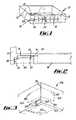
- FIG. 1is a highly schematic and part diagrammatic perspective view of a container according to the present invention
- FIG. 2is a partial horizontal section along the line II—II in FIG. 1 ;
- FIG. 3is a view from below of a second embodiment of the invention.
- FIG. 4is a highly diagrammatic plan view illustrating RF characteristics of the embodiment of FIG. 3 ;
- FIG. 5illustrates schematically the manner in which the invention may be used.
- FIG. 1shows a container 10 which, in this example, has a generally rectangular base 12 , from which four walls 14 are upstanding.
- the container 10 shown in the drawingis intended for commercial use for storage and delivery of retail products, for instance, and may therefore be provided with formations to allow containers to stack, nest or the like, with lids, and other features which are conventional in themselves. These features are within the expertise of the skilled man and are not described in detail herein.
- the containeris intended to be returnable, so that it may be sent out filled, and then returned empty for refilling and re-use.
- the container 10comprises antenna means 16 for radio frequency (RF) use, and connection means indicated generally at 18 for receiving a removable drive circuit means 20 (FIG. 2 ).
- the drive circuit 20is operable to communicate by means of the antenna 16 when connected therewith.
- the connections 18serve, in use, to connect an installed drive circuit 20 with the antenna 16 to allow the drive circuit 20 to communicate in this manner.
- the container 10is, in this example, a moulded plastics product.
- Conducting elements 22are embedded within one wall of the container 10 during manufacture and are arranged to form the RF antenna 16 .
- Thislies within the plane of the wall 14 and is therefore ultimately limited in its size by the dimensions of the wall, although in practice, other features of the wall (particularly features required for stacking, nesting and the like) may impose additional limitations on the size or form of the antenna 16 .
- connection means 18are shown in more detail in FIG. 2.
- a recess 24is formed in the wall 14 .
- the recess 24may be open to the outer face of the wall 14 or the interior of the container, and may be provided with a cover (not shown).
- Connectors 26are provided within the recess 24 and are in electrical connection with conductors 28 embedded in the wall 14 to provide electrical connection between the connectors 26 and the conducting elements 22 of the antenna 16 .
- a drive circuit 20can be removably installed in the position illustrated in FIG. 2 , as follows. It is envisaged that the drive circuit 20 will be in the form of an integrated circuit “chip” having connecting terminals in the form of “legs” which can be pushed into the connectors 26 when the drive circuit 20 is installed. The connectors 26 then provide mechanical grip on the legs of the circuit 20 , providing mechanical location to retain the circuit 20 . The connectors 26 also provide electrical connection with the circuit 20 , to complete the electrical connections between the circuit 20 and the antenna 16 , thereby allowing the drive circuit 20 to use the antenna 16 for RF communication with a remote location.
- the drive circuit 20may be passive, to respond to a signal received via the antenna 16 from an external source, and to respond in predetermined manner.
- the drive circuit 20may be active, to initiate transmission using the antenna 16 .
- a power supplysuch as a battery, will be required or may be incorporated within the circuit 20 .
- the circuit 20in use, will be able to report data relating to the container 10 when interrogated (in the case of a passive circuit) or spontaneously.
- the circuit 20may report its identity, from which the identity of the container in which it is installed may be obtained from appropriate records, and thus the contents of the container identified.
- the circuit 20may identify the container to which it has been installed, or the contents of that container. In the latter case, some form of re-writeable memory could be used, together with a facility to change stored data.
- the drive circuit 20would be “loaded” with appropriate data at the time it is installed in the container 10 . For instance, as the container 10 is loaded with produce, the circuit 20 can be “loaded” with corresponding data to identify the produce.
- circuit 20allows it to be readily replaced. This may be necessary in the case of damage or malfunction.
- passive circuits 20might have identification data permanently stored in them, allowing an appropriate circuit to be installed when a container is filled, to identify the contents. The circuit would then be removed when the container is emptied.
- removable circuitsallow alternative circuits to be installed (so long as they are compatible with the spatial requirements of the connectors 26 ). For instance, as technologies change and improve, circuits 20 can be updated. However, it is envisaged that RF antenna design is sufficiently well established that upgraded antennas are unlikely to be required within the expected life of a container.
- FIG. 3shows an alternative embodiment of container 10 A, again having a base 12 A, walls 14 A and an antenna arrangement 16 A embedded within the container during manufacture.
- the antenna 16 Acomprises several different antenna portions, as follows.
- a first antenna portion 30 A and second portion 30 Bare within walls 14 A which meet at an edge 32 Their location is illustrated by broken lines in FIG. 3 . Detail of their construction is not shown.
- the conducting elements of the two portions 30 A, 30 Bare interconnected to form a single RF antenna having limbs which are generally perpendicular to each other, for reasons to be explained below.
- a recess 24 Ais provided near the lower end of the edge 32 , adjacent the base 32 A, with connection means 18 A for connecting a drive circuit (not shown) to the antenna portion 30 A, and therefore to the portion 30 B.
- the third antenna portion 30 Cis located within the base 12 A and is thus generally perpendicular to both portions 30 A, 30 B.
- the portion 30 Cforms an independent antenna, separately connected to the recess 24 A by connection means 18 A and thus actuable by a drive circuit independently of actuation of the portions 30 A, 30 B.
- the different orientations of the portions 30 A,B,Cwill affect the directional nature of the RF communication available to a drive circuit 20 . This is illustrated schematically in FIG. 4 . If it is assumed that the antenna portions 30 A, 30 B, 30 C have a coverage pattern which is maximum in a direction generally perpendicular to the plane of the portions, then when viewed from above, the container 10 A will have two perpendicular main directions of RF communication, as illustrated by the shaded areas 34 . The portion 30 C will contribute a similar, but vertically oriented pattern. Consequently, the combined coverage of the portions 30 A,B,C includes all six orthogonal directions, relative to the container 10 , so that it is envisaged that adequate communication can be established with substantially any point relative to the container. Thus, in an automated system, adequate communication with the circuit 20 can be maintained substantially regardless of the orientation of the container.
- FIG. 5An automated system which can take advantage of these features is illustrated in FIG. 5 .
- Thisshows a pallet 36 on which a number of containers 10 , 10 A are stacked.
- the pallet 36is passing through an arch 38 which includes RF aerials connected to a system indicated at 40 , such as a stock control system.
- a system indicated at 40such as a stock control system.
- RF communicationis established between the system 40 and the drive circuit 20 of each container on the pallet 36 , by means of the antennas within the arch 38 , and the antennas 16 , 16 A incorporated in the containers 10 , 10 A.
- the system 40can identify each container and contents as the pallet 36 passes through the arch 38 , so that inventory records, or the like, can be updated.
- the system 40may be active, to provide signals for interrogating the circuits 20 , which may be passive.
- the circuits 20may be active to provide signals which will be received by a passive system 40 when within range of the arch 38 .
- both the system 40 and the circuits 20could be active, to allow interaction as a container passes through the arch.
- FIG. 3the description set out above has illustrated how two antenna portions with different orientations can together form a single antenna, whose radiation pattern will depend on the particular shape and form of the antenna portions, but will be more omni-directional than a simple plane antenna.
- FIG. 3has indicated that several antenna portions could be independently available to a drive circuit installed in a container.
- the nature, layout and number of independent antenna portionsare design criteria within the scope of the invention, to be chosen according to the intended application of the container and in particular, the nature and location of systems with which the circuits 20 will be required to communicate.
- an antenna incorporated in the containercould be constructed in order to be resonant at more than one frequency band, such as by the use of traps, filters or other arrangements to electrically connect and disconnect conducting elements or parts, to change the electrical characteristics of the antenna.
- traps, filters or other arrangementsto electrically connect and disconnect conducting elements or parts, to change the electrical characteristics of the antenna.
- Many techniques of this natureare well known in the field of RF antenna design.
- the example described aboveis a container.
- Some returnable items for use in storage and transportationare given other names, such as pallets (on which a stack of containers is secured for easier handling), pallet boxes (large containers having pallet features in their base, for compatibility with pallet handling equipment), dollies and trollies (on which stack of containers can be wheeled around) and stillages (an open-sided pallet box used particularly in the automotive industry.
- palletson which a stack of containers is secured for easier handling
- pallet boxeslarge containers having pallet features in their base, for compatibility with pallet handling equipment
- dollies and trollieson which stack of containers can be wheeled around
- stillagesan open-sided pallet box used particularly in the automotive industry.
Landscapes
- Engineering & Computer Science (AREA)
- Physics & Mathematics (AREA)
- General Physics & Mathematics (AREA)
- Theoretical Computer Science (AREA)
- Mechanical Engineering (AREA)
- Computer Hardware Design (AREA)
- Microelectronics & Electronic Packaging (AREA)
- Details Of Rigid Or Semi-Rigid Containers (AREA)
- Details Of Aerials (AREA)
Abstract
Description
Claims (15)
Applications Claiming Priority (3)
| Application Number | Priority Date | Filing Date | Title |
|---|---|---|---|
| GB0005038.5 | 2000-03-03 | ||
| GB0005038AGB0005038D0 (en) | 2000-03-03 | 2000-03-03 | Container |
| PCT/GB2001/000900WO2001067384A1 (en) | 2000-03-03 | 2001-03-05 | Returnable item for use in storage and transportation of commercials goods |
Publications (2)
| Publication Number | Publication Date |
|---|---|
| US20030179092A1 US20030179092A1 (en) | 2003-09-25 |
| US6844857B2true US6844857B2 (en) | 2005-01-18 |
Family
ID=9886814
Family Applications (1)
| Application Number | Title | Priority Date | Filing Date |
|---|---|---|---|
| US10/220,799Expired - Fee RelatedUS6844857B2 (en) | 2000-03-03 | 2001-03-05 | Returnable item for use in storage and transportation of commercial goods |
Country Status (7)
| Country | Link |
|---|---|
| US (1) | US6844857B2 (en) |
| EP (1) | EP1261937B1 (en) |
| AU (1) | AU2001235832A1 (en) |
| DE (1) | DE60108478T2 (en) |
| ES (1) | ES2234813T3 (en) |
| GB (2) | GB0005038D0 (en) |
| WO (1) | WO2001067384A1 (en) |
Cited By (4)
| Publication number | Priority date | Publication date | Assignee | Title |
|---|---|---|---|---|
| US20050241548A1 (en)* | 2000-01-24 | 2005-11-03 | Muirhead Scott A W | Thermoformed platform having a communications device |
| US20070108296A1 (en)* | 2005-11-14 | 2007-05-17 | Konopka John A | Radio frequency identification devices and methods |
| US20070171080A1 (en)* | 2000-01-24 | 2007-07-26 | Scott Muirhead | Material handling apparatus with a cellular communications device |
| US20080122610A1 (en)* | 2000-01-24 | 2008-05-29 | Nextreme L.L.C. | RF-enabled pallet |
Families Citing this family (14)
| Publication number | Priority date | Publication date | Assignee | Title |
|---|---|---|---|---|
| GB0209755D0 (en)* | 2002-04-29 | 2002-06-05 | Alumasc Construction Products | Slot drain |
| US6938772B2 (en) | 2002-06-04 | 2005-09-06 | Rehrig Pacific Company | Portable storage container |
| US7823728B2 (en) | 2005-03-04 | 2010-11-02 | Rehrig Pacific Company | Storage container with support structure for multiple levels of nesting |
| US7347148B2 (en)* | 2005-05-11 | 2008-03-25 | Hunter Paine Enterprises, Llc | Shipping pallet equipped with a non-structural member carrying a readable device |
| GB2428424A (en) | 2005-07-16 | 2007-01-31 | Linpac Materials Handling Ltd | Stackable crate having a RF identification device |
| US7484621B2 (en) | 2005-09-09 | 2009-02-03 | Rehrig Pacific Company | Tray |
| US7757947B2 (en)* | 2006-03-17 | 2010-07-20 | Siemens Aktiengesellschaft | R.F.I.D. enabled storage bin and method for tracking inventory |
| US20080055045A1 (en)* | 2006-08-31 | 2008-03-06 | 3M Innovative Properties Company | Rfid tag including a three-dimensional antenna |
| US8289163B2 (en) | 2007-09-27 | 2012-10-16 | 3M Innovative Properties Company | Signal line structure for a radio-frequency identification system |
| US8717244B2 (en) | 2007-10-11 | 2014-05-06 | 3M Innovative Properties Company | RFID tag with a modified dipole antenna |
| US7982616B2 (en) | 2008-02-14 | 2011-07-19 | 3M Innovative Properties Company | Radio frequency identification (RFID) tag including a three-dimensional loop antenna |
| US8712334B2 (en)* | 2008-05-20 | 2014-04-29 | Micron Technology, Inc. | RFID device using single antenna for multiple resonant frequency ranges |
| EP2390199B1 (en) | 2010-05-27 | 2013-07-10 | Rehrig Pacific Company | Collapsible dual height stacking container |
| WO2015013026A2 (en)* | 2013-07-24 | 2015-01-29 | Promega Corporation | Processes for distribution and use of a mobile rfid container |
Citations (13)
| Publication number | Priority date | Publication date | Assignee | Title |
|---|---|---|---|---|
| FR2697801A1 (en) | 1992-11-06 | 1994-05-13 | Allibert Equipement | Materials handling pallet tracking process - uses electronic transponder located in corner of pallet storing data on pallet route, destination and contents |
| DE4313049A1 (en) | 1993-04-21 | 1994-10-27 | Michael L Hoeffgen | Shipping container |
| EP0635305A1 (en) | 1993-07-22 | 1995-01-25 | Societe D'etudes, De Gestion, D'engineering | Platelike apparatus for the conservation of a liquid or powdery product |
| FR2772529A1 (en) | 1997-12-17 | 1999-06-18 | Smurfit Worldwide Research Eur | SUBSRAT PROVIDED WITH AN ELECTRONIC DEVICE |
| FR2777378A1 (en) | 1998-04-14 | 1999-10-15 | Jean Claude Mongrenier | DEVICE FOR ASSOCIATING A CONTAINER AND A COMPUTER MONITORING DEVICE FOR ITS CONTENT |
| US5995048A (en) | 1996-05-31 | 1999-11-30 | Lucent Technologies Inc. | Quarter wave patch antenna |
| WO1999065002A1 (en) | 1998-06-09 | 1999-12-16 | Motorola Inc. | Radio frequency identification tag having an article integrated antenna |
| WO2000005675A1 (en) | 1998-07-20 | 2000-02-03 | Integrated Silicon Design Pty. Ltd. | Metal screened electronic labelling system |
| US6023242A (en)* | 1998-07-07 | 2000-02-08 | Northern Telecom Limited | Establishing communication with a satellite |
| US6054961A (en)* | 1997-09-08 | 2000-04-25 | Andrew Corporation | Dual band, glass mount antenna and flexible housing therefor |
| US6128471A (en)* | 1995-08-21 | 2000-10-03 | Nortel Networks Corporation | Telecommunication method and system for communicating with multiple terminals in a building through multiple antennas |
| US6400321B1 (en)* | 2000-07-17 | 2002-06-04 | Apple Computer, Inc. | Surface-mountable patch antenna with coaxial cable feed for wireless applications |
| US6542117B1 (en)* | 1997-05-14 | 2003-04-01 | Inmarsat Limited | Satellite apparatus with omnidirectional and manually steerable directional antenna |
- 2000
- 2000-03-03GBGB0005038Apatent/GB0005038D0/ennot_activeCeased
- 2001
- 2001-03-05GBGB0220851Apatent/GB2379836B/ennot_activeRevoked
- 2001-03-05DEDE2001608478patent/DE60108478T2/ennot_activeExpired - Fee Related
- 2001-03-05WOPCT/GB2001/000900patent/WO2001067384A1/enactiveIP Right Grant
- 2001-03-05USUS10/220,799patent/US6844857B2/ennot_activeExpired - Fee Related
- 2001-03-05AUAU2001235832Apatent/AU2001235832A1/ennot_activeAbandoned
- 2001-03-05ESES01907967Tpatent/ES2234813T3/ennot_activeExpired - Lifetime
- 2001-03-05EPEP01907967Apatent/EP1261937B1/ennot_activeExpired - Lifetime
Patent Citations (13)
| Publication number | Priority date | Publication date | Assignee | Title |
|---|---|---|---|---|
| FR2697801A1 (en) | 1992-11-06 | 1994-05-13 | Allibert Equipement | Materials handling pallet tracking process - uses electronic transponder located in corner of pallet storing data on pallet route, destination and contents |
| DE4313049A1 (en) | 1993-04-21 | 1994-10-27 | Michael L Hoeffgen | Shipping container |
| EP0635305A1 (en) | 1993-07-22 | 1995-01-25 | Societe D'etudes, De Gestion, D'engineering | Platelike apparatus for the conservation of a liquid or powdery product |
| US6128471A (en)* | 1995-08-21 | 2000-10-03 | Nortel Networks Corporation | Telecommunication method and system for communicating with multiple terminals in a building through multiple antennas |
| US5995048A (en) | 1996-05-31 | 1999-11-30 | Lucent Technologies Inc. | Quarter wave patch antenna |
| US6542117B1 (en)* | 1997-05-14 | 2003-04-01 | Inmarsat Limited | Satellite apparatus with omnidirectional and manually steerable directional antenna |
| US6054961A (en)* | 1997-09-08 | 2000-04-25 | Andrew Corporation | Dual band, glass mount antenna and flexible housing therefor |
| FR2772529A1 (en) | 1997-12-17 | 1999-06-18 | Smurfit Worldwide Research Eur | SUBSRAT PROVIDED WITH AN ELECTRONIC DEVICE |
| FR2777378A1 (en) | 1998-04-14 | 1999-10-15 | Jean Claude Mongrenier | DEVICE FOR ASSOCIATING A CONTAINER AND A COMPUTER MONITORING DEVICE FOR ITS CONTENT |
| WO1999065002A1 (en) | 1998-06-09 | 1999-12-16 | Motorola Inc. | Radio frequency identification tag having an article integrated antenna |
| US6023242A (en)* | 1998-07-07 | 2000-02-08 | Northern Telecom Limited | Establishing communication with a satellite |
| WO2000005675A1 (en) | 1998-07-20 | 2000-02-03 | Integrated Silicon Design Pty. Ltd. | Metal screened electronic labelling system |
| US6400321B1 (en)* | 2000-07-17 | 2002-06-04 | Apple Computer, Inc. | Surface-mountable patch antenna with coaxial cable feed for wireless applications |
Cited By (15)
| Publication number | Priority date | Publication date | Assignee | Title |
|---|---|---|---|---|
| US20080122610A1 (en)* | 2000-01-24 | 2008-05-29 | Nextreme L.L.C. | RF-enabled pallet |
| US7804400B2 (en) | 2000-01-24 | 2010-09-28 | Nextreme, Llc | Thermoformed platform having a communications device |
| US9230227B2 (en) | 2000-01-24 | 2016-01-05 | Nextreme, Llc | Pallet |
| US20070163472A1 (en)* | 2000-01-24 | 2007-07-19 | Scott Muirhead | Material handling apparatus having a reader/writer |
| US20070171080A1 (en)* | 2000-01-24 | 2007-07-26 | Scott Muirhead | Material handling apparatus with a cellular communications device |
| US7342496B2 (en) | 2000-01-24 | 2008-03-11 | Nextreme Llc | RF-enabled pallet |
| US20060243174A1 (en)* | 2000-01-24 | 2006-11-02 | Nextreme, L.L.C. | Thermoformed platform having a communications device |
| US7752980B2 (en) | 2000-01-24 | 2010-07-13 | Nextreme Llc | Material handling apparatus having a reader/writer |
| US20050241548A1 (en)* | 2000-01-24 | 2005-11-03 | Muirhead Scott A W | Thermoformed platform having a communications device |
| US7789024B2 (en) | 2000-01-24 | 2010-09-07 | Nextreme, Llc | Thermoformed platform having a communications device |
| US20080121339A1 (en)* | 2000-01-24 | 2008-05-29 | Nextreme L.L.C. | Thermoformed platform having a communications device |
| US7948371B2 (en) | 2000-01-24 | 2011-05-24 | Nextreme Llc | Material handling apparatus with a cellular communications device |
| US8077040B2 (en) | 2000-01-24 | 2011-12-13 | Nextreme, Llc | RF-enabled pallet |
| US8585850B2 (en) | 2000-01-24 | 2013-11-19 | Nextreme, Llc | Thermoformed platform having a communications device |
| US20070108296A1 (en)* | 2005-11-14 | 2007-05-17 | Konopka John A | Radio frequency identification devices and methods |
Also Published As
| Publication number | Publication date |
|---|---|
| EP1261937B1 (en) | 2005-01-19 |
| US20030179092A1 (en) | 2003-09-25 |
| GB2379836A (en) | 2003-03-19 |
| DE60108478T2 (en) | 2006-03-23 |
| DE60108478D1 (en) | 2005-02-24 |
| AU2001235832A1 (en) | 2001-09-17 |
| GB0005038D0 (en) | 2000-04-26 |
| GB0220851D0 (en) | 2002-10-16 |
| GB2379836A8 (en) | 2003-03-24 |
| WO2001067384A1 (en) | 2001-09-13 |
| ES2234813T3 (en) | 2005-07-01 |
| GB2379836B (en) | 2004-08-11 |
| EP1261937A1 (en) | 2002-12-04 |
Similar Documents
| Publication | Publication Date | Title |
|---|---|---|
| US6844857B2 (en) | Returnable item for use in storage and transportation of commercial goods | |
| US6563425B2 (en) | RFID passive repeater system and apparatus | |
| US7948371B2 (en) | Material handling apparatus with a cellular communications device | |
| US9230227B2 (en) | Pallet | |
| AU2001284768A1 (en) | RFID passive repeater system and apparatus | |
| US6724308B2 (en) | RFID tracking method and system | |
| GB2360422A (en) | Identifying transponders on difficult to read items | |
| US20060208899A1 (en) | RFID relay antenna, RFID system, container, disposition method, communication confirmation method, and package construction | |
| US20030156501A1 (en) | Trackable storage unit system and method | |
| US6998983B2 (en) | System and method for tracking data related to containers using RF technology | |
| WO2002075684A1 (en) | Rfid tracking method and system | |
| EP1693807A1 (en) | RFID tracking method and system | |
| US6388630B1 (en) | Waveguide for transmitting RF energy through an RF barrier | |
| GB2428424A (en) | Stackable crate having a RF identification device | |
| KR20140137129A (en) | Smart distribution management system | |
| WO2008018199A1 (en) | Pallet | |
| JPWO2008029534A1 (en) | Wireless IC tag | |
| JP2006347560A (en) | palette |
Legal Events
| Date | Code | Title | Description |
|---|---|---|---|
| AS | Assignment | Owner name:C. G. PAXTON LIMITED, UNITED KINGDOM Free format text:ASSIGNMENT OF ASSIGNORS INTEREST;ASSIGNORS:LOFTUS, STEPHEN CLIVE;COOPER, MARTIN;REEL/FRAME:013935/0212 Effective date:20030322 | |
| AS | Assignment | Owner name:LINPAC MOULDINGS LIMITED, GREAT BRITAIN Free format text:ASSIGNMENT OF ASSIGNORS INTEREST;ASSIGNOR:C.G. PAXTON LIMITED;REEL/FRAME:015414/0642 Effective date:20041012 | |
| FPAY | Fee payment | Year of fee payment:4 | |
| AS | Assignment | Owner name:LINPAC ALLIBERT LIMITED, UNITED KINGDOM Free format text:CHANGE OF NAME;ASSIGNOR:LINPAC MATERIALS HANDLING LIMITED;REEL/FRAME:022127/0894 Effective date:20070629 | |
| AS | Assignment | Owner name:LINPAC MATERIALS HANDLING LIMITED, UNITED KINGDOM Free format text:ASSIGNMENT OF ASSIGNORS INTEREST;ASSIGNOR:LINPAC MOULDINGS LIMITED;REEL/FRAME:022191/0149 Effective date:20051007 | |
| REMI | Maintenance fee reminder mailed | ||
| LAPS | Lapse for failure to pay maintenance fees | ||
| STCH | Information on status: patent discontinuation | Free format text:PATENT EXPIRED DUE TO NONPAYMENT OF MAINTENANCE FEES UNDER 37 CFR 1.362 | |
| FP | Expired due to failure to pay maintenance fee | Effective date:20130118 |