US6844810B2 - Arrangement of a data coupler for power line communications - Google Patents
Arrangement of a data coupler for power line communicationsDownload PDFInfo
- Publication number
- US6844810B2 US6844810B2US10/688,154US68815403AUS6844810B2US 6844810 B2US6844810 B2US 6844810B2US 68815403 AUS68815403 AUS 68815403AUS 6844810 B2US6844810 B2US 6844810B2
- Authority
- US
- United States
- Prior art keywords
- power line
- capacitor
- communication device
- secondary winding
- signal
- Prior art date
- Legal status (The legal status is an assumption and is not a legal conclusion. Google has not performed a legal analysis and makes no representation as to the accuracy of the status listed.)
- Expired - Lifetime
Links
Images


Classifications
- H—ELECTRICITY
- H04—ELECTRIC COMMUNICATION TECHNIQUE
- H04B—TRANSMISSION
- H04B3/00—Line transmission systems
- H04B3/54—Systems for transmission via power distribution lines
- H04B3/542—Systems for transmission via power distribution lines the information being in digital form
- H—ELECTRICITY
- H01—ELECTRIC ELEMENTS
- H01F—MAGNETS; INDUCTANCES; TRANSFORMERS; SELECTION OF MATERIALS FOR THEIR MAGNETIC PROPERTIES
- H01F38/00—Adaptations of transformers or inductances for specific applications or functions
- H01F38/02—Adaptations of transformers or inductances for specific applications or functions for non-linear operation
- H—ELECTRICITY
- H01—ELECTRIC ELEMENTS
- H01P—WAVEGUIDES; RESONATORS, LINES, OR OTHER DEVICES OF THE WAVEGUIDE TYPE
- H01P1/00—Auxiliary devices
- H01P1/32—Non-reciprocal transmission devices
- H—ELECTRICITY
- H03—ELECTRONIC CIRCUITRY
- H03H—IMPEDANCE NETWORKS, e.g. RESONANT CIRCUITS; RESONATORS
- H03H7/00—Multiple-port networks comprising only passive electrical elements as network components
- H03H7/01—Frequency selective two-port networks
- H03H7/0115—Frequency selective two-port networks comprising only inductors and capacitors
- H—ELECTRICITY
- H03—ELECTRONIC CIRCUITRY
- H03H—IMPEDANCE NETWORKS, e.g. RESONANT CIRCUITS; RESONATORS
- H03H7/00—Multiple-port networks comprising only passive electrical elements as network components
- H03H7/01—Frequency selective two-port networks
- H03H7/0138—Electrical filters or coupling circuits
- H—ELECTRICITY
- H03—ELECTRONIC CIRCUITRY
- H03H—IMPEDANCE NETWORKS, e.g. RESONANT CIRCUITS; RESONATORS
- H03H7/00—Multiple-port networks comprising only passive electrical elements as network components
- H03H7/38—Impedance-matching networks
- H—ELECTRICITY
- H04—ELECTRIC COMMUNICATION TECHNIQUE
- H04B—TRANSMISSION
- H04B3/00—Line transmission systems
- H04B3/02—Details
- H04B3/36—Repeater circuits
- H04B3/38—Repeater circuits for signals in two different frequency ranges transmitted in opposite directions over the same transmission path
- H—ELECTRICITY
- H04—ELECTRIC COMMUNICATION TECHNIQUE
- H04B—TRANSMISSION
- H04B3/00—Line transmission systems
- H04B3/54—Systems for transmission via power distribution lines
- H—ELECTRICITY
- H04—ELECTRIC COMMUNICATION TECHNIQUE
- H04B—TRANSMISSION
- H04B3/00—Line transmission systems
- H04B3/54—Systems for transmission via power distribution lines
- H04B3/56—Circuits for coupling, blocking, or by-passing of signals
- H—ELECTRICITY
- H04—ELECTRIC COMMUNICATION TECHNIQUE
- H04M—TELEPHONIC COMMUNICATION
- H04M11/00—Telephonic communication systems specially adapted for combination with other electrical systems
- H04M11/04—Telephonic communication systems specially adapted for combination with other electrical systems with alarm systems, e.g. fire, police or burglar alarm systems
- H—ELECTRICITY
- H01—ELECTRIC ELEMENTS
- H01F—MAGNETS; INDUCTANCES; TRANSFORMERS; SELECTION OF MATERIALS FOR THEIR MAGNETIC PROPERTIES
- H01F17/00—Fixed inductances of the signal type
- H01F17/04—Fixed inductances of the signal type with magnetic core
- H01F17/06—Fixed inductances of the signal type with magnetic core with core substantially closed in itself, e.g. toroid
- H—ELECTRICITY
- H01—ELECTRIC ELEMENTS
- H01F—MAGNETS; INDUCTANCES; TRANSFORMERS; SELECTION OF MATERIALS FOR THEIR MAGNETIC PROPERTIES
- H01F38/00—Adaptations of transformers or inductances for specific applications or functions
- H01F38/14—Inductive couplings
- H01F2038/143—Inductive couplings for signals
- H—ELECTRICITY
- H03—ELECTRONIC CIRCUITRY
- H03H—IMPEDANCE NETWORKS, e.g. RESONANT CIRCUITS; RESONATORS
- H03H1/00—Constructional details of impedance networks whose electrical mode of operation is not specified or applicable to more than one type of network
- H03H2001/0092—Inductor filters, i.e. inductors whose parasitic capacitance is of relevance to consider it as filter
- H—ELECTRICITY
- H03—ELECTRONIC CIRCUITRY
- H03H—IMPEDANCE NETWORKS, e.g. RESONANT CIRCUITS; RESONATORS
- H03H7/00—Multiple-port networks comprising only passive electrical elements as network components
- H03H7/01—Frequency selective two-port networks
- H03H2007/013—Notch or bandstop filters
- H—ELECTRICITY
- H04—ELECTRIC COMMUNICATION TECHNIQUE
- H04B—TRANSMISSION
- H04B2203/00—Indexing scheme relating to line transmission systems
- H04B2203/54—Aspects of powerline communications not already covered by H04B3/54 and its subgroups
- H04B2203/5404—Methods of transmitting or receiving signals via power distribution lines
- H04B2203/5408—Methods of transmitting or receiving signals via power distribution lines using protocols
- H—ELECTRICITY
- H04—ELECTRIC COMMUNICATION TECHNIQUE
- H04B—TRANSMISSION
- H04B2203/00—Indexing scheme relating to line transmission systems
- H04B2203/54—Aspects of powerline communications not already covered by H04B3/54 and its subgroups
- H04B2203/5404—Methods of transmitting or receiving signals via power distribution lines
- H04B2203/5425—Methods of transmitting or receiving signals via power distribution lines improving S/N by matching impedance, noise reduction, gain control
- H—ELECTRICITY
- H04—ELECTRIC COMMUNICATION TECHNIQUE
- H04B—TRANSMISSION
- H04B2203/00—Indexing scheme relating to line transmission systems
- H04B2203/54—Aspects of powerline communications not already covered by H04B3/54 and its subgroups
- H04B2203/5462—Systems for power line communications
- H04B2203/5479—Systems for power line communications using repeaters
- H—ELECTRICITY
- H04—ELECTRIC COMMUNICATION TECHNIQUE
- H04B—TRANSMISSION
- H04B2203/00—Indexing scheme relating to line transmission systems
- H04B2203/54—Aspects of powerline communications not already covered by H04B3/54 and its subgroups
- H04B2203/5462—Systems for power line communications
- H04B2203/5483—Systems for power line communications using coupling circuits
- H—ELECTRICITY
- H04—ELECTRIC COMMUNICATION TECHNIQUE
- H04B—TRANSMISSION
- H04B2203/00—Indexing scheme relating to line transmission systems
- H04B2203/54—Aspects of powerline communications not already covered by H04B3/54 and its subgroups
- H04B2203/5462—Systems for power line communications
- H04B2203/5491—Systems for power line communications using filtering and bypassing
Definitions
- the present inventionrelates to power line communications, and more particularly, to configurations of data couplers for power line communications.
- a data coupler for power line communicationscouples a data signal between the power line and a communication device such as a modem.
- the data couplerexhibits a cutoff frequency. Below the cutoff frequency, coupling attenuation between the power line and the communication device becomes excessive.
- the data couplermay be either an inductive coupler or a capacitive coupler.
- An inductive coupler for a power lineshould ideally have a magnetization inductance with an impedance that is large as compared to an impedance of the communication device. As the magnetization inductance is in shunt with a signal and inductively loads the signal, a low magnetization inductance is undesirable.
- a capacitive couplermay be efficient for use on a power line, especially a low voltage line.
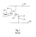
- FIG. 1is a schematic of a prior art capacitive coupler as may be used to couple a power line modem to a secondary power line.
- a power line 400nominally neutral, is connected to a shield terminal of a coax connector 420 .
- a power line 405nominally an energized phase line, is connected to a center conductor contact of connector 420 via a fuse 415 and a capacitor 410 .
- a modem 435is connected, via a cable 430 and a connector 425 , to connector 420 .
- the capacitive couplerthus couples high frequency signals between modem 435 and power lines 400 and 405 .
- capacitor 410is several nanofarads, large enough to have negligible reactance at signal frequency and small enough to have a large reactance at power frequency.
- a ceramic capacitor with an appropriate dielectricmay be used in such a coupler and provides a low impedance to signal frequencies in the MHz range.
- a lead connecting such a capacitor to the power linemay be relatively long, and may have an impedance far exceeding the capacitor's impedance at signal frequencies.
- wires in a low voltage rack arrangementare typically spaced 20 centimeters (cm) apart, and a 10 AWG wire of that length has an inductance of 0.21 microhenry (uH) or nearly 40 ohms at 30 megahertz (MHz).
- uHmicrohenry
- MHzmegahertz
- the capacitive couplerneed to connect to a non-adjacent wire, the impedance could increase to 80 or 120 ohms.
- a typical capacitive couplermust be fused, and a fuse impedance is added in series, a total series inductive impedance can be significant in comparison to a typical modem's 50 ohm impedance.
- the arrangementincludes an inductive coupler that employs a power line conductor as a primary winding, a capacitor connected across a secondary winding of the inductive coupler for creating a resonant circuit with the secondary winding at a frequency within a desired frequency band, and an impedance matching transformer for connecting a communications device to the secondary winding.
- the resonant circuithas a loaded Q consistent with the desired bandwidth.
- An alternative arrangementincludes a capacitor in series with a conductive cylinder between the power line and the communication device, where the capacitor is for blocking power line voltage while passing a signal between the power line and the communication device, and the conductive cylinder appears as a low inductance to the signal.
- FIG. 1is a schematic of a prior art capacitive coupler.
- FIG. 2is a schematic of an impedance matching circuit for an inductive coupler.
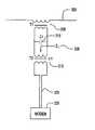
- FIG. 3illustrates a circuit with a capacitive coupler using low-inductance leads.
- FIG. 4is a schematic diagram of the circuit shown in FIG. 3 .
- a low frequency inductive coupler in accordance with the present inventionextends cutoff frequency downwards, to a lower frequency, without resorting to an addition of heavy magnetic cores.
- the inductive coupleris clamped around an energized power line conductor of the power line. Assume that the power line conductor passing through a core of the coupler serves as a primary winding for the inductive coupler. Since the coupler is clamped around the power line conductor, and since the power line conductor serves as a primary winding, the coupler has only a one-turn primary winding.
- the physical dimensions of the power line conductortypically require that the core be large with a long magnetic circuit path. An air gap may be required to prevent saturation of the core. Both of these factors reduce the inductance of the coupler.
- a classic method of reducing reactive loading in a circuitis to resonate an offending reactance with an opposite reactance.
- a shunt capacitormay be connected across a secondary coil of the inductive coupler to neutralize magnetization inductance.
- an impedance matching transformeris connected between the coupler and a modem so as to adjust the modem's impedance, as reflected across the coupler circuit, to provide a low enough loaded Q as to increase bandwidth so as to be similar to a width of the modem frequency band.
- FIG. 2shows an impedance-matching circuit through which a modem 325 is connected to an inductive coupler 305 .
- a power line 300passes through a core of inductive coupler 305 .
- a signal transformer 315with turns ratio n:1, improves impedance matching between inductive coupler 305 and modem 325 .
- the combination of inductive coupler 305 and signal transformer 315can provide a very wide bandpass, but the low frequency response of the combination will be limited to that determined by a magnetization inductance of inductive coupler 305 and an impedance 330 that is reflected from modem 325 .
- Capacitor 310resonates the magnetization inductance and provides a frequency band around the resonant frequency where a loading effect of the magnetization inductance is reduced, and signal attenuation across inductive coupler 305 is reduced. The effect of capacitor 310 is to lower the cutoff frequency of inductive coupler 305 , allowing inductive coupler 305 to operate at a lower frequency than would otherwise be possible with a given level of magnetization inductance.
- the methodincludes connecting a capacitor across a secondary winding of the inductive coupler for creating a resonant circuit with the secondary winding at a frequency within a desired frequency band, and connecting the communications device to the secondary winding via an impedance matching transformer.
- the resonant circuithas a loaded Q consistent with the desired bandwidth.
- FIG. 3is an illustration of a physical implementation of a capacitive coupler 500 .
- Power lines 400 and 405 , capacitor 410 , fuse 415 and connector 420retain the same identification as in FIG. 1 .
- modem 435is connected, via cable 430 and connector 425 , to connector 420 .
- Electrically conductive cylinder sections 505 and 510each have a diameter in the range of 1 to 3 cm, which is many times larger than diameters of wires, and thus provide connections to power lines 400 and 405 with negligible inductance.
- Conductive cylinder sections 505 and 510 and an insulating cylinder segment 515form a mechanically rigid body, which may have a common axis.
- Power line 400i.e., a neutral line
- One end of capacitive coupler 500is electrically connected to, and physically supported by, power line 400 .
- a bar 550 with a slot 560 and a wing nut 565provide a mechanism for tightening section 505 onto power line 400 .
- capacitive coupler 500is electrically connected to power line 405 by a wire 520 and a clamp 525 .
- Wire 520is soldered or brazed to conductive cylinder section 510 , and has sufficient stiffness and strength to support capacitive coupler 500 on power line 405 , should upper support provided by the combination of bar 550 , slot 560 and wing nut 565 , or wire 400 , fail.
- Clamp 525is a standard clamp, commonly available to utility linemen.
- FIG. 4is a schematic diagram of the arrangement shown in FIG. 3 .
- Cable 430 , connectors 425 and 420 , capacitor 410 , fuse 415 , and conductors 505 and 510provide a signal path between modem 435 and power lines 400 and 405 .
- conductive cylinder sections 505 and 510exhibit inductances that are negligible in comparison to the impedance of modem 435 and capacitor 410 , thus reducing coupling loss.
- the methodincludes installing a capacitor in series with a conductive cylinder between the power line and the communication device.
- the capacitoris for blocking power line voltage while passing a signal between the power line and the communication device, and the conductive cylinder appears as a low inductance to the signal.
- the methodmay include installing a high interruption current fuse in series with the capacitor.
Landscapes
- Engineering & Computer Science (AREA)
- Power Engineering (AREA)
- Signal Processing (AREA)
- Computer Networks & Wireless Communication (AREA)
- Physics & Mathematics (AREA)
- Nonlinear Science (AREA)
- Cable Transmission Systems, Equalization Of Radio And Reduction Of Echo (AREA)
- Filters And Equalizers (AREA)
- Near-Field Transmission Systems (AREA)
- Insulation, Fastening Of Motor, Generator Windings (AREA)
- Radio Relay Systems (AREA)
- Coils Or Transformers For Communication (AREA)
- Mobile Radio Communication Systems (AREA)
Abstract
Description
The present application is claiming priority of U.S. Provisional Patent Application Ser. No. 60/419,174, filed on Oct. 17, 2002, the content of which is herein incorporated by reference.
1. Field of the Invention
The present invention relates to power line communications, and more particularly, to configurations of data couplers for power line communications.
2. Description of the Related Art
A data coupler for power line communications couples a data signal between the power line and a communication device such as a modem. The data coupler exhibits a cutoff frequency. Below the cutoff frequency, coupling attenuation between the power line and the communication device becomes excessive. The data coupler may be either an inductive coupler or a capacitive coupler.
An inductive coupler for a power line should ideally have a magnetization inductance with an impedance that is large as compared to an impedance of the communication device. As the magnetization inductance is in shunt with a signal and inductively loads the signal, a low magnetization inductance is undesirable.
A capacitive coupler may be efficient for use on a power line, especially a low voltage line.
The value ofcapacitor 410 is several nanofarads, large enough to have negligible reactance at signal frequency and small enough to have a large reactance at power frequency.
A ceramic capacitor with an appropriate dielectric may be used in such a coupler and provides a low impedance to signal frequencies in the MHz range. However, a lead connecting such a capacitor to the power line may be relatively long, and may have an impedance far exceeding the capacitor's impedance at signal frequencies.
For example, wires in a low voltage rack arrangement are typically spaced 20 centimeters (cm) apart, and a 10 AWG wire of that length has an inductance of 0.21 microhenry (uH) or nearly 40 ohms at 30 megahertz (MHz). Should the capacitive coupler need to connect to a non-adjacent wire, the impedance could increase to 80 or 120 ohms. As a typical capacitive coupler must be fused, and a fuse impedance is added in series, a total series inductive impedance can be significant in comparison to a typical modem's 50 ohm impedance.
There is provided an arrangement of components for coupling data between a power line and a communication device. The arrangement includes an inductive coupler that employs a power line conductor as a primary winding, a capacitor connected across a secondary winding of the inductive coupler for creating a resonant circuit with the secondary winding at a frequency within a desired frequency band, and an impedance matching transformer for connecting a communications device to the secondary winding. The resonant circuit has a loaded Q consistent with the desired bandwidth.
An alternative arrangement includes a capacitor in series with a conductive cylinder between the power line and the communication device, where the capacitor is for blocking power line voltage while passing a signal between the power line and the communication device, and the conductive cylinder appears as a low inductance to the signal.
A low frequency inductive coupler in accordance with the present invention extends cutoff frequency downwards, to a lower frequency, without resorting to an addition of heavy magnetic cores. The inductive coupler is clamped around an energized power line conductor of the power line. Assume that the power line conductor passing through a core of the coupler serves as a primary winding for the inductive coupler. Since the coupler is clamped around the power line conductor, and since the power line conductor serves as a primary winding, the coupler has only a one-turn primary winding. The physical dimensions of the power line conductor typically require that the core be large with a long magnetic circuit path. An air gap may be required to prevent saturation of the core. Both of these factors reduce the inductance of the coupler.
A classic method of reducing reactive loading in a circuit is to resonate an offending reactance with an opposite reactance. In the case of an inductive coupler with a shunt inductance, a shunt capacitor may be connected across a secondary coil of the inductive coupler to neutralize magnetization inductance.
In the case of a broadband modem, such as those using spread spectrum, the resonance is likely to be too sharp, and thus is effective over too narrow a sub-band. As described herein, an impedance matching transformer is connected between the coupler and a modem so as to adjust the modem's impedance, as reflected across the coupler circuit, to provide a low enough loaded Q as to increase bandwidth so as to be similar to a width of the modem frequency band.
There is thus provided a method for configuring an inductive coupler to a communication device. The method includes connecting a capacitor across a secondary winding of the inductive coupler for creating a resonant circuit with the secondary winding at a frequency within a desired frequency band, and connecting the communications device to the secondary winding via an impedance matching transformer. The resonant circuit has a loaded Q consistent with the desired bandwidth.
The other end ofcapacitive coupler 500 is electrically connected topower line 405 by awire 520 and aclamp 525.Wire 520 is soldered or brazed toconductive cylinder section 510, and has sufficient stiffness and strength to supportcapacitive coupler 500 onpower line 405, should upper support provided by the combination ofbar 550,slot 560 andwing nut 565, orwire 400, fail.Clamp 525 is a standard clamp, commonly available to utility linemen.
There is thus provided a method for coupling data between a power line and a communication device. The method includes installing a capacitor in series with a conductive cylinder between the power line and the communication device. The capacitor is for blocking power line voltage while passing a signal between the power line and the communication device, and the conductive cylinder appears as a low inductance to the signal. Additionally, the method may include installing a high interruption current fuse in series with the capacitor.
It should be understood that various alternatives, combinations and modifications of the teachings described herein could be devised by those skilled in the art. The present invention is intended to embrace all such alternatives, modifications and variances that fall within the scope of the appended claims.
Claims (6)
1. A method for configuring components for power line communications, comprising:
installing an inductive coupler that employs a power line conductor as a primary winding;
connecting a capacitor across a secondary winding of said inductive coupler for creating a resonant circuit with said secondary winding at a frequency within a desired frequency band; and
connecting a communications device to said secondary winding via an impedance matching transformer,
wherein said resonant circuit has a loaded Q consistent with said desired bandwidth.
2. A method for coupling data between a power line and a communication device, comprising:
installing a capacitor in series with a conductive cylinder between said power line and said communication device,
wherein said capacitor is for blocking power line voltage while passing a signal between said power line and said communication device, and
wherein said conductive cylinder appears as a low inductance to said signal.
3. The method ofclaim 2 , further comprising installing a high interruption current fuse in series with said capacitor.
4. An arrangement of components for coupling data between a power line and a communication device, comprising:
an inductive coupler that employs a power line conductor as a primary winding;
a capacitor connected across a secondary winding of said inductive coupler for creating a resonant circuit with said secondary winding at a frequency within a desired frequency band; and
an impedance matching transformer for connecting a communications device to said secondary winding,
wherein said resonant circuit has a loaded Q consistent with said desired bandwidth.
5. An arrangement of components for coupling data between a power line and a communication device, comprising:
a capacitor in series with a conductive cylinder between said power line and said communication device,
wherein said capacitor is for blocking power line voltage while passing a signal between said power line and said communication device, and
wherein said conductive cylinder appears as a low inductance to said signal.
6. The arrangement ofclaim 5 , further comprising a high interruption current fuse in series with said capacitor.
Priority Applications (1)
| Application Number | Priority Date | Filing Date | Title |
|---|---|---|---|
| US10/688,154US6844810B2 (en) | 2002-10-17 | 2003-10-17 | Arrangement of a data coupler for power line communications |
Applications Claiming Priority (2)
| Application Number | Priority Date | Filing Date | Title |
|---|---|---|---|
| US41917402P | 2002-10-17 | 2002-10-17 | |
| US10/688,154US6844810B2 (en) | 2002-10-17 | 2003-10-17 | Arrangement of a data coupler for power line communications |
Publications (2)
| Publication Number | Publication Date |
|---|---|
| US20040090284A1 US20040090284A1 (en) | 2004-05-13 |
| US6844810B2true US6844810B2 (en) | 2005-01-18 |
Family
ID=32108037
Family Applications (5)
| Application Number | Title | Priority Date | Filing Date |
|---|---|---|---|
| US10/688,262Expired - Fee RelatedUS7109835B2 (en) | 2002-10-17 | 2003-10-17 | Highly insulated inductive data couplers |
| US10/688,154Expired - LifetimeUS6844810B2 (en) | 2002-10-17 | 2003-10-17 | Arrangement of a data coupler for power line communications |
| US10/688,263Expired - LifetimeUS7376385B2 (en) | 2002-10-17 | 2003-10-17 | Repeaters sharing a common medium for communications |
| US10/688,264Expired - LifetimeUS7005943B2 (en) | 2002-10-17 | 2003-10-17 | Filter for segmenting power lines for communications |
| US11/205,804Expired - LifetimeUS7286035B2 (en) | 2002-10-17 | 2005-08-17 | Highly insulated inductive data couplers |
Family Applications Before (1)
| Application Number | Title | Priority Date | Filing Date |
|---|---|---|---|
| US10/688,262Expired - Fee RelatedUS7109835B2 (en) | 2002-10-17 | 2003-10-17 | Highly insulated inductive data couplers |
Family Applications After (3)
| Application Number | Title | Priority Date | Filing Date |
|---|---|---|---|
| US10/688,263Expired - LifetimeUS7376385B2 (en) | 2002-10-17 | 2003-10-17 | Repeaters sharing a common medium for communications |
| US10/688,264Expired - LifetimeUS7005943B2 (en) | 2002-10-17 | 2003-10-17 | Filter for segmenting power lines for communications |
| US11/205,804Expired - LifetimeUS7286035B2 (en) | 2002-10-17 | 2005-08-17 | Highly insulated inductive data couplers |
Country Status (11)
| Country | Link |
|---|---|
| US (5) | US7109835B2 (en) |
| EP (4) | EP1561226A4 (en) |
| JP (4) | JP2006507721A (en) |
| KR (4) | KR20050049548A (en) |
| CN (4) | CN100530457C (en) |
| AU (3) | AU2003277438A1 (en) |
| BR (4) | BR0315356A (en) |
| CA (4) | CA2502122A1 (en) |
| EA (4) | EA007883B1 (en) |
| MX (4) | MXPA05003903A (en) |
| WO (4) | WO2004036879A2 (en) |
Cited By (39)
| Publication number | Priority date | Publication date | Assignee | Title |
|---|---|---|---|---|
| US20020002040A1 (en)* | 2000-04-19 | 2002-01-03 | Kline Paul A. | Method and apparatus for interfacing RF signals to medium voltage power lines |
| US20030169155A1 (en)* | 2000-04-14 | 2003-09-11 | Mollenkopf James Douglas | Power line communication system and method of using the same |
| US20040003934A1 (en)* | 2002-06-24 | 2004-01-08 | Cope Leonard David | Power line coupling device and method of using the same |
| US20040056734A1 (en)* | 2001-05-18 | 2004-03-25 | Davidow Clifford A. | Medium voltage signal coupling structure for last leg power grid high-speed data network |
| US20040110483A1 (en)* | 2002-12-10 | 2004-06-10 | Mollenkopf James Douglas | Power line communication sytem and method |
| US20040113757A1 (en)* | 2002-12-10 | 2004-06-17 | White Melvin Joseph | Power line communication system and method of operating the same |
| US20040113756A1 (en)* | 2002-12-10 | 2004-06-17 | Mollenkopf James Douglas | Device and method for coupling with electrical distribution network infrastructure to provide communications |
| US20040142599A1 (en)* | 2003-01-21 | 2004-07-22 | Cope Leonard D. | Power line coupling device and method of using the same |
| US20040227622A1 (en)* | 2003-05-13 | 2004-11-18 | Giannini Paul M. | Device and method for communicating data signals through multiple power line conductors |
| US20040227621A1 (en)* | 2000-04-14 | 2004-11-18 | Cope Leonard D. | Power line communication apparatus and method of using the same |
| US20050254516A1 (en)* | 2000-04-19 | 2005-11-17 | Serconet, Ltd. | Network combining wired and non-wired segments |
| US20050275495A1 (en)* | 2002-06-21 | 2005-12-15 | Pridmore Charles F Jr | Power line coupling device and method of using the same |
| US20060044076A1 (en)* | 2004-09-02 | 2006-03-02 | Law Robinson P S | Serial signal injection using capacitive and transformer couplings for power line communications |
| US20060087382A1 (en)* | 2004-10-25 | 2006-04-27 | Ambient Corporation | Inductive coupler for power line communications |
| US20060125609A1 (en)* | 2000-08-09 | 2006-06-15 | Kline Paul A | Power line coupling device and method of using the same |
| US7064654B2 (en) | 2002-12-10 | 2006-06-20 | Current Technologies, Llc | Power line communication system and method of operating the same |
| US20060203981A1 (en)* | 2000-03-20 | 2006-09-14 | Serconet Ltd. | Telephone outlet for implementing a local area network over telephone lines and a local area network using such outlets |
| US20060244571A1 (en)* | 2005-04-29 | 2006-11-02 | Yaney David S | Power line coupling device and method of use |
| US7132819B1 (en) | 2002-11-12 | 2006-11-07 | Current Technologies, Llc | Floating power supply and method of using the same |
| US20060262881A1 (en)* | 2005-05-20 | 2006-11-23 | Yehuda Cern | Power line communications interface and surge protector |
| US20060291546A1 (en)* | 2005-06-28 | 2006-12-28 | International Broadband Electric Communications, Inc. | Device and method for enabling communications signals using a medium voltage power line |
| US20060290476A1 (en)* | 2005-06-28 | 2006-12-28 | International Broadband Electric Communications, Inc. | Improved Coupling of Communications Signals to a Power Line |
| US20070013491A1 (en)* | 2005-07-15 | 2007-01-18 | International Broadband Electric Communications, Inc. | Coupling Communications Signals To Underground Power Lines |
| US20070014529A1 (en)* | 2005-07-15 | 2007-01-18 | International Broadband Electric Communications, Inc. | Improved Coupling of Communications Signals to a Power Line |
| US7245201B1 (en) | 2000-08-09 | 2007-07-17 | Current Technologies, Llc | Power line coupling device and method of using the same |
| WO2007112507A1 (en)* | 2006-04-04 | 2007-10-11 | Adc Gmbh | Power line communications coupler |
| US7394204B1 (en) | 2005-01-13 | 2008-07-01 | Universal Lighting Technologies, Inc. | Zero crossing detection of line voltage/current of variable amplitude |
| US20080231111A1 (en)* | 2004-02-16 | 2008-09-25 | Serconet Ltd. | Outlet add-on module |
| US20080297327A1 (en)* | 2005-07-15 | 2008-12-04 | International Broadband Electric Communications, Inc. | Coupling of Communications Signals to a Power Line |
| US20090002094A1 (en)* | 2007-06-26 | 2009-01-01 | Radtke William O | Power Line Coupling Device and Method |
| US20090002137A1 (en)* | 2007-06-26 | 2009-01-01 | Radtke William O | Power Line Coupling Device and Method |
| US20090085726A1 (en)* | 2007-09-27 | 2009-04-02 | Radtke William O | Power Line Communications Coupling Device and Method |
| US20090240449A1 (en)* | 2007-12-20 | 2009-09-24 | Tollgrade Communications, Inc. | Power Distribution Monitoring System And Method |
| US20090315700A1 (en)* | 2006-07-25 | 2009-12-24 | Jonathan Ephriam David Hurwitz | Dual Transformer Communication Interface |
| US20100226380A1 (en)* | 2009-03-03 | 2010-09-09 | Aboundi, Inc. | Transmission line adapter and system |
| US7852874B2 (en) | 1998-07-28 | 2010-12-14 | Mosaid Technologies Incorporated | Local area network of serial intelligent cells |
| US7873058B2 (en) | 2004-11-08 | 2011-01-18 | Mosaid Technologies Incorporated | Outlet with analog signal adapter, a method for use thereof and a network using said outlet |
| US7990908B2 (en) | 2002-11-13 | 2011-08-02 | Mosaid Technologies Incorporated | Addressable outlet, and a network using the same |
| US20160294218A1 (en)* | 2015-04-02 | 2016-10-06 | AMTB Technology | Power line communication control system |
Families Citing this family (90)
| Publication number | Priority date | Publication date | Assignee | Title |
|---|---|---|---|---|
| US7176786B2 (en)* | 2000-01-20 | 2007-02-13 | Current Technologies, Llc | Method of isolating data in a power line communications network |
| US7199699B1 (en) | 2002-02-19 | 2007-04-03 | Current Technologies, Llc | Facilitating communication with power line communication devices |
| KR20050049548A (en)* | 2002-10-17 | 2005-05-25 | 앰비언트 코오퍼레이션 | Repeaters sharing a common medium for communications |
| NO20040110L (en)* | 2004-01-09 | 2005-07-11 | Geir Monsen Vavik | Signal repeater system |
| WO2006012681A1 (en)* | 2004-08-02 | 2006-02-09 | Donald Malcolm Ross Yelland | Method and device for power line head-end data transmission |
| EA200701963A1 (en)* | 2005-05-20 | 2008-04-28 | Эмбиент Корпорейшн | INDUCTIVE CONNECTOR FOR DATA TRANSMISSION SYSTEMS BY ELECTRICAL WIRES |
| US7808985B2 (en)* | 2006-11-21 | 2010-10-05 | Gigle Networks Sl | Network repeater |
| EP1770870B1 (en)* | 2005-10-03 | 2019-04-03 | Avago Technologies International Sales Pte. Limited | Powerline communication device and method |
| US8406239B2 (en)* | 2005-10-03 | 2013-03-26 | Broadcom Corporation | Multi-wideband communications over multiple mediums |
| US8213895B2 (en)* | 2005-10-03 | 2012-07-03 | Broadcom Europe Limited | Multi-wideband communications over multiple mediums within a network |
| US20070076666A1 (en)* | 2005-10-03 | 2007-04-05 | Riveiro Juan C | Multi-Wideband Communications over Power Lines |
| JP4611172B2 (en)* | 2005-10-20 | 2011-01-12 | 関西電力株式会社 | Power line carrier communication equipment |
| US7519328B2 (en) | 2006-01-19 | 2009-04-14 | Murata Manufacturing Co., Ltd. | Wireless IC device and component for wireless IC device |
| US9064198B2 (en) | 2006-04-26 | 2015-06-23 | Murata Manufacturing Co., Ltd. | Electromagnetic-coupling-module-attached article |
| WO2007138919A1 (en) | 2006-05-26 | 2007-12-06 | Murata Manufacturing Co., Ltd. | Data coupler |
| US7860146B2 (en)* | 2006-07-06 | 2010-12-28 | Gigle Networks, Inc. | Adaptative multi-carrier code division multiple access |
| US8885814B2 (en) | 2006-07-25 | 2014-11-11 | Broadcom Europe Limited | Feedback impedance control for driving a signal |
| CN1976253B (en)* | 2006-12-12 | 2010-12-01 | 京信通信技术(广州)有限公司 | Digital microwave relay communication system and realizing method thereof |
| US8235299B2 (en) | 2007-07-04 | 2012-08-07 | Murata Manufacturing Co., Ltd. | Wireless IC device and component for wireless IC device |
| EP2138962B1 (en) | 2007-04-26 | 2012-01-04 | Murata Manufacturing Co. Ltd. | Wireless ic device |
| US7714682B2 (en)* | 2007-06-21 | 2010-05-11 | Current Technologies, Llc | Power line data signal attenuation device and method |
| EP2166617B1 (en) | 2007-07-09 | 2015-09-30 | Murata Manufacturing Co. Ltd. | Wireless ic device |
| EP2166490B1 (en) | 2007-07-17 | 2015-04-01 | Murata Manufacturing Co. Ltd. | Wireless ic device and electronic apparatus |
| CN102915462B (en) | 2007-07-18 | 2017-03-01 | 株式会社村田制作所 | Wireless IC device |
| KR100908775B1 (en)* | 2007-09-28 | 2009-07-22 | 한국전력공사 | Power line communication device and method |
| KR100952737B1 (en)* | 2007-12-28 | 2010-04-13 | 주식회사 피플웍스 | Overcurrent Shutdown Coupler |
| EP2251934B1 (en) | 2008-03-03 | 2018-05-02 | Murata Manufacturing Co. Ltd. | Wireless ic device and wireless communication system |
| EP2284949B1 (en) | 2008-05-21 | 2016-08-03 | Murata Manufacturing Co. Ltd. | Wireless ic device |
| WO2009145007A1 (en) | 2008-05-26 | 2009-12-03 | 株式会社村田製作所 | Wireless ic device system and method for authenticating wireless ic device |
| EP2320519B1 (en) | 2008-08-19 | 2017-04-12 | Murata Manufacturing Co., Ltd. | Wireless ic device and method for manufacturing same |
| US7956689B2 (en)* | 2008-10-13 | 2011-06-07 | Broadcom Corporation | Programmable gain amplifier and transconductance compensation system |
| US7795973B2 (en) | 2008-10-13 | 2010-09-14 | Gigle Networks Ltd. | Programmable gain amplifier |
| JP4605318B2 (en) | 2008-11-17 | 2011-01-05 | 株式会社村田製作所 | Antenna and wireless IC device |
| CN103500873B (en) | 2009-01-09 | 2016-08-31 | 株式会社村田制作所 | Wireless ic device and wireless ic module |
| EP2385580B1 (en) | 2009-01-30 | 2014-04-09 | Murata Manufacturing Co., Ltd. | Antenna and wireless ic device |
| DE102009009271A1 (en)* | 2009-02-17 | 2010-06-24 | Siemens Aktiengesellschaft | Repeater pair i.e. radio-repeater pair, for use in wireless, intermeshed network, has transmission lines transmitting signals received from repeater to another repeater in frequency range |
| JP5278954B2 (en)* | 2009-03-24 | 2013-09-04 | シャープ株式会社 | Power line communication apparatus and communication method in power line communication apparatus |
| JP5510450B2 (en) | 2009-04-14 | 2014-06-04 | 株式会社村田製作所 | Wireless IC device |
| EP2568534A3 (en) | 2009-04-21 | 2014-05-14 | Murata Manufacturing Co., Ltd. | Antenna devie and method of setting resonant frequency of antenna device |
| JP5182431B2 (en) | 2009-09-28 | 2013-04-17 | 株式会社村田製作所 | Wireless IC device and environmental state detection method using the same |
| JP5201270B2 (en) | 2009-09-30 | 2013-06-05 | 株式会社村田製作所 | Circuit board and manufacturing method thereof |
| JP5304580B2 (en) | 2009-10-02 | 2013-10-02 | 株式会社村田製作所 | Wireless IC device |
| CN102576939B (en) | 2009-10-16 | 2015-11-25 | 株式会社村田制作所 | Antenna and wireless ic device |
| JP5418600B2 (en) | 2009-10-27 | 2014-02-19 | 株式会社村田製作所 | Transceiver and RFID tag reader |
| WO2011055701A1 (en) | 2009-11-04 | 2011-05-12 | 株式会社村田製作所 | Communication terminal and information processing system |
| JP5327334B2 (en) | 2009-11-04 | 2013-10-30 | 株式会社村田製作所 | Communication terminal and information processing system |
| CN104617374B (en) | 2009-11-20 | 2018-04-06 | 株式会社村田制作所 | Mobile communication terminal |
| CN101741337B (en)* | 2009-11-24 | 2012-10-31 | 北京北方微电子基地设备工艺研究中心有限责任公司 | Impedance adjusting device and impedance matching system comprising same |
| GB2488450B (en) | 2009-12-24 | 2014-08-20 | Murata Manufacturing Co | Antenna and mobile terminal |
| JP5403146B2 (en) | 2010-03-03 | 2014-01-29 | 株式会社村田製作所 | Wireless communication device and wireless communication terminal |
| WO2011108340A1 (en) | 2010-03-03 | 2011-09-09 | 株式会社村田製作所 | Wireless communication module and wireless communication device |
| CN102576940B (en) | 2010-03-12 | 2016-05-04 | 株式会社村田制作所 | Wireless communication devices and metal article processed |
| JP5370581B2 (en) | 2010-03-24 | 2013-12-18 | 株式会社村田製作所 | RFID system |
| WO2011122163A1 (en) | 2010-03-31 | 2011-10-06 | 株式会社村田製作所 | Antenna and wireless communication device |
| EP2390891A1 (en)* | 2010-05-24 | 2011-11-30 | ABB Technology AG | A very fast transient suppressing device |
| WO2012005278A1 (en) | 2010-07-08 | 2012-01-12 | 株式会社村田製作所 | Antenna and rfid device |
| GB2537773A (en) | 2010-07-28 | 2016-10-26 | Murata Manufacturing Co | Antenna apparatus and communication terminal instrument |
| JP5423897B2 (en) | 2010-08-10 | 2014-02-19 | 株式会社村田製作所 | Printed wiring board and wireless communication system |
| EP2424120A1 (en) | 2010-08-31 | 2012-02-29 | ABB Research Ltd. | Power line communication filter arrangement |
| JP5630506B2 (en) | 2010-09-30 | 2014-11-26 | 株式会社村田製作所 | Wireless IC device |
| WO2012050037A1 (en) | 2010-10-12 | 2012-04-19 | 株式会社村田製作所 | Antenna apparatus and communication terminal apparatus |
| CN102971909B (en) | 2010-10-21 | 2014-10-15 | 株式会社村田制作所 | Communication terminal device |
| WO2012093541A1 (en) | 2011-01-05 | 2012-07-12 | 株式会社村田製作所 | Wireless communication device |
| CN103299325B (en) | 2011-01-14 | 2016-03-02 | 株式会社村田制作所 | RFID chip packaging and RFID tags |
| CN103119786B (en) | 2011-02-28 | 2015-07-22 | 株式会社村田制作所 | Wireless communication device |
| WO2012121185A1 (en) | 2011-03-08 | 2012-09-13 | 株式会社村田製作所 | Antenna device and communication terminal apparatus |
| WO2012137717A1 (en) | 2011-04-05 | 2012-10-11 | 株式会社村田製作所 | Wireless communication device |
| WO2012141070A1 (en) | 2011-04-13 | 2012-10-18 | 株式会社村田製作所 | Wireless ic device and wireless communication terminal |
| WO2012157596A1 (en) | 2011-05-16 | 2012-11-22 | 株式会社村田製作所 | Wireless ic device |
| KR101338173B1 (en) | 2011-07-14 | 2013-12-06 | 가부시키가이샤 무라타 세이사쿠쇼 | Wireless communication device |
| WO2013011856A1 (en) | 2011-07-15 | 2013-01-24 | 株式会社村田製作所 | Wireless communication device |
| CN204189963U (en) | 2011-07-19 | 2015-03-04 | 株式会社村田制作所 | Antenna assembly and communication terminal |
| WO2013035821A1 (en) | 2011-09-09 | 2013-03-14 | 株式会社村田製作所 | Antenna device and wireless device |
| JP5344108B1 (en) | 2011-12-01 | 2013-11-20 | 株式会社村田製作所 | Wireless IC device and manufacturing method thereof |
| EP2688145A1 (en) | 2012-01-30 | 2014-01-22 | Murata Manufacturing Co., Ltd. | Wireless ic device |
| JP5464307B2 (en) | 2012-02-24 | 2014-04-09 | 株式会社村田製作所 | ANTENNA DEVICE AND WIRELESS COMMUNICATION DEVICE |
| JP2013197715A (en)* | 2012-03-16 | 2013-09-30 | Sumitomo Electric Ind Ltd | Communication device and communication system |
| CN104487985B (en) | 2012-04-13 | 2020-06-26 | 株式会社村田制作所 | RFID tag inspection method and inspection device |
| KR101622185B1 (en) | 2012-05-30 | 2016-05-18 | 엘에스산전 주식회사 | Design of a power line coupler and a power line coupler designed thereof |
| RU2616591C2 (en)* | 2013-01-23 | 2017-04-18 | Бертель С.П.А. | Line filter for transmission systems on ac transmission lines of average/high voltage |
| JP5596202B1 (en)* | 2013-04-04 | 2014-09-24 | 日本ビソー株式会社 | Gondola device and communication method |
| CN104242991B (en)* | 2014-08-29 | 2016-07-06 | 戴葵 | A kind of ultra wide band electrically powerline carrier communication block device structure |
| CN107871601B (en)* | 2016-09-27 | 2020-10-27 | 西门子公司 | Current Transformers and Current Transformer-Based DC Sources |
| CN108878105B (en)* | 2017-05-08 | 2021-07-30 | 台达电子工业股份有限公司 | transformer |
| CN108878118B (en) | 2017-05-08 | 2021-06-11 | 台达电子工业股份有限公司 | Transformer device |
| CN109120307B (en)* | 2018-08-07 | 2021-06-22 | 南京邮电大学 | Power line carrier communication system and band-pass matching coupler thereof |
| RU2705421C1 (en)* | 2018-12-25 | 2019-11-07 | Общество с ограниченной ответственностью "ТЕКОН Микропроцессорные технологии" | Method of transmitting data over a bus, a communication system for realizing said method and an automatic protection device for preventing an emergency situation at a control object |
| US10794165B2 (en) | 2019-02-14 | 2020-10-06 | National Service Alliance—Houston LLC | Power distribution trailer for an electric driven hydraulic fracking system |
| CA3072788C (en) | 2019-02-14 | 2024-02-27 | National Service Alliance - Houston Llc | Parameter monitoring and control for an electric driven hydraulic fracking system |
| EP4027528A1 (en) | 2021-01-08 | 2022-07-13 | NXP USA, Inc. | Communications system |
Citations (4)
| Publication number | Priority date | Publication date | Assignee | Title |
|---|---|---|---|---|
| US4142178A (en)* | 1977-04-25 | 1979-02-27 | Westinghouse Electric Corp. | High voltage signal coupler for a distribution network power line carrier communication system |
| US5684450A (en)* | 1992-10-22 | 1997-11-04 | Norweb Plc | Electricity distribution and/or power transmission network and filter for telecommunication over power lines |
| US5717685A (en)* | 1989-04-28 | 1998-02-10 | Abraham; Charles | Transformer coupler for communication over various lines |
| US5856776A (en)* | 1993-11-24 | 1999-01-05 | Remote Metering Systems, Ltd. | Method and apparatus for signal coupling at medium voltage in a power line carrier communications system |
Family Cites Families (36)
| Publication number | Priority date | Publication date | Assignee | Title |
|---|---|---|---|---|
| FR759125A (en)* | 1932-08-03 | 1934-01-29 | Siemens Ag | Coupling arrangement for high frequency service on high voltage lines |
| US6452482B1 (en)* | 1999-12-30 | 2002-09-17 | Ambient Corporation | Inductive coupling of a data signal to a power transmission cable |
| US3924223A (en) | 1974-02-21 | 1975-12-02 | Westinghouse Electric Corp | Power line communication system having a protective terminating impedance arrangement |
| DE2417023C3 (en)* | 1974-04-08 | 1981-06-11 | Messwandler-Bau Gmbh, 8600 Bamberg | Single-conductor current transformer that can be installed in a fully insulated, metal-enclosed high-voltage switchgear |
| US3973087A (en)* | 1974-12-05 | 1976-08-03 | General Electric Company | Signal repeater for power line access data system |
| US4030058A (en)* | 1976-03-30 | 1977-06-14 | Westinghouse Electric Corporation | Inductive coupler |
| US4007434A (en)* | 1976-04-14 | 1977-02-08 | Nasa | Notch filter |
| US4184056A (en)* | 1978-10-05 | 1980-01-15 | Gte Laboratories Incorporated | Fault locating system for optical telecommunications |
| EP0031061B1 (en) | 1979-12-22 | 1984-04-11 | BROWN, BOVERI & CIE Aktiengesellschaft Mannheim | Blocking filter for appliances with carrier frequency utilisation in low-tension networks |
| US4327349A (en)* | 1980-03-19 | 1982-04-27 | General Electric Company | Transformer core having charge dissipation facility |
| EP0063636B2 (en)* | 1981-04-28 | 1992-12-30 | Sprecher + Schuh AG | Current transformer with annular case to be built in a metal cast high-tension switchgear installation |
| US4434396A (en)* | 1981-11-02 | 1984-02-28 | Montague Herbert R | Power line transient suppression circuit |
| US4777652A (en)* | 1982-07-27 | 1988-10-11 | A.R.F. Products | Radio communication systems for underground mines |
| US4471133A (en)* | 1983-05-31 | 1984-09-11 | General Electric Company | Continuous method for making methyldimethoxysilane |
| JPS6069919A (en)* | 1983-09-26 | 1985-04-20 | Matsushita Electric Ind Co Ltd | Block filter for power line carrier control equipment |
| US4675579A (en)* | 1985-03-18 | 1987-06-23 | General Electric Company | Coupling of carrier signal from power line |
| US4697166A (en)* | 1986-08-11 | 1987-09-29 | Nippon Colin Co., Ltd. | Method and apparatus for coupling transceiver to power line carrier system |
| GB8628004D0 (en)* | 1986-11-22 | 1986-12-31 | Emlux Ltd | Filtering electrical signals |
| US4760484A (en) | 1986-12-18 | 1988-07-26 | Honeywell, Inc. | Protective inductive devices with increased ability to absord volt-seconds in an electrical conductor |
| DE9315875U1 (en) | 1993-10-18 | 1993-12-16 | Siemens AG, 80333 München | Device for coupling or receiving electrical signals into or from an energy transmission cable |
| GB9417359D0 (en)* | 1994-08-26 | 1994-10-19 | Norweb Plc | A power transmission network and filter therefor |
| US5668658A (en)* | 1995-02-28 | 1997-09-16 | Nec Corporation | Transfer of repeater information signals in in-line optical amplifier repeater system |
| CA2256469A1 (en)* | 1996-05-29 | 1997-12-04 | Abb Ab | Transformer/reactor |
| US6032020A (en)* | 1997-07-28 | 2000-02-29 | Motorola, Inc. | Multi-repeater communication system |
| US6041065A (en)* | 1997-08-13 | 2000-03-21 | Hewlett-Packard Company | Flexible multi-frequency repeater |
| US6191589B1 (en) | 1999-03-29 | 2001-02-20 | George A. Spencer | Test circuit for an AFCI/GFCI circuit breaker |
| US6996200B2 (en)* | 1999-12-23 | 2006-02-07 | Analog Devices, Inc. | Device for use in controlling a sample rate |
| US6690916B1 (en)* | 2000-10-10 | 2004-02-10 | Motorola, Inc. | Radio network for radio communication in an enclosed environment and a repeater for such a radio network |
| US7007305B2 (en)* | 2001-09-06 | 2006-02-28 | Genlyte Thomas Group Llc | Repeater amplifier with signal firewall protection for power line carrier communication networks |
| KR20040104688A (en)* | 2002-05-03 | 2004-12-10 | 앰비언트 코오퍼레이션 | Construction of Medium Voltage Power Line Data Couplers |
| US6993317B2 (en)* | 2002-10-02 | 2006-01-31 | Amperion, Inc. | Method and system for signal repeating in powerline communications |
| KR20050049548A (en)* | 2002-10-17 | 2005-05-25 | 앰비언트 코오퍼레이션 | Repeaters sharing a common medium for communications |
| US7230935B2 (en)* | 2002-10-24 | 2007-06-12 | Widefi, Inc. | Physical layer repeater with selective use of higher layer functions based on network operating conditions |
| US6985715B2 (en)* | 2003-05-29 | 2006-01-10 | Amperion, Inc. | Method and device for frequency translation in powerline communications |
| US20060205343A1 (en)* | 2005-03-11 | 2006-09-14 | Runyon Donald L | Wireless repeater with feedback suppression features |
| US7078996B1 (en)* | 2005-05-20 | 2006-07-18 | Ambient Corporation | Inductive coupler for power line communications |
- 2003
- 2003-10-17KRKR1020057006465Apatent/KR20050049548A/ennot_activeWithdrawn
- 2003-10-17KRKR1020057006649Apatent/KR100991921B1/ennot_activeExpired - Fee Related
- 2003-10-17BRBR0315356-8Apatent/BR0315356A/ennot_activeApplication Discontinuation
- 2003-10-17USUS10/688,262patent/US7109835B2/ennot_activeExpired - Fee Related
- 2003-10-17WOPCT/US2003/033081patent/WO2004036879A2/ennot_activeApplication Discontinuation
- 2003-10-17WOPCT/US2003/033082patent/WO2004036813A2/ennot_activeApplication Discontinuation
- 2003-10-17EAEA200500669Apatent/EA007883B1/ennot_activeIP Right Cessation
- 2003-10-17EAEA200500670Apatent/EA006985B1/ennot_activeIP Right Cessation
- 2003-10-17CNCNB2003801016100Apatent/CN100530457C/ennot_activeExpired - Fee Related
- 2003-10-17CNCNA2003801015023Apatent/CN1706175A/enactivePending
- 2003-10-17CNCNA2003801015019Apatent/CN1706099A/enactivePending
- 2003-10-17CACA002502122Apatent/CA2502122A1/ennot_activeAbandoned
- 2003-10-17EPEP03809179Apatent/EP1561226A4/ennot_activeWithdrawn
- 2003-10-17JPJP2004545508Apatent/JP2006507721A/enactivePending
- 2003-10-17MXMXPA05003903Apatent/MXPA05003903A/enunknown
- 2003-10-17JPJP2004545558Apatent/JP4361488B2/ennot_activeExpired - Fee Related
- 2003-10-17EPEP03809155Apatent/EP1552678A2/ennot_activeWithdrawn
- 2003-10-17JPJP2004545509Apatent/JP2006503505A/enactivePending
- 2003-10-17JPJP2004545507Apatent/JP2006503504A/ennot_activeWithdrawn
- 2003-10-17MXMXPA05004088Apatent/MXPA05004088A/enactiveIP Right Grant
- 2003-10-17WOPCT/US2003/033080patent/WO2004036772A2/enactiveApplication Filing
- 2003-10-17BRBR0315307-0Apatent/BR0315307A/ennot_activeIP Right Cessation
- 2003-10-17MXMXPA05004090Apatent/MXPA05004090A/ennot_activeApplication Discontinuation
- 2003-10-17AUAU2003277438Apatent/AU2003277438A1/ennot_activeAbandoned
- 2003-10-17AUAU2003277439Apatent/AU2003277439A1/ennot_activeAbandoned
- 2003-10-17CACA002502104Apatent/CA2502104A1/ennot_activeAbandoned
- 2003-10-17USUS10/688,154patent/US6844810B2/ennot_activeExpired - Lifetime
- 2003-10-17EAEA200500668Apatent/EA200500668A1/enunknown
- 2003-10-17EPEP03809154Apatent/EP1556947A4/ennot_activeWithdrawn
- 2003-10-17WOPCT/US2003/033188patent/WO2004036601A2/enactiveSearch and Examination
- 2003-10-17BRBR0315492-0Apatent/BR0315492A/ennot_activeIP Right Cessation
- 2003-10-17USUS10/688,263patent/US7376385B2/ennot_activeExpired - Lifetime
- 2003-10-17USUS10/688,264patent/US7005943B2/ennot_activeExpired - Lifetime
- 2003-10-17CACA002502107Apatent/CA2502107A1/ennot_activeAbandoned
- 2003-10-17CACA2502547Apatent/CA2502547C/ennot_activeExpired - Fee Related
- 2003-10-17BRBR0315364-9Apatent/BR0315364A/ennot_activeApplication Discontinuation
- 2003-10-17EPEP03809153Apatent/EP1552677A4/ennot_activeWithdrawn
- 2003-10-17MXMXPA05004087Apatent/MXPA05004087A/enactiveIP Right Grant
- 2003-10-17CNCNA2003801015038Apatent/CN1706176A/enactivePending
- 2003-10-17AUAU2003301390Apatent/AU2003301390A1/ennot_activeAbandoned
- 2003-10-17KRKR1020057006561Apatent/KR20050065603A/ennot_activeWithdrawn
- 2003-10-17EAEA200500667Apatent/EA200500667A1/enunknown
- 2003-10-17KRKR1020057006461Apatent/KR20050055763A/ennot_activeWithdrawn
- 2005
- 2005-08-17USUS11/205,804patent/US7286035B2/ennot_activeExpired - Lifetime
Patent Citations (4)
| Publication number | Priority date | Publication date | Assignee | Title |
|---|---|---|---|---|
| US4142178A (en)* | 1977-04-25 | 1979-02-27 | Westinghouse Electric Corp. | High voltage signal coupler for a distribution network power line carrier communication system |
| US5717685A (en)* | 1989-04-28 | 1998-02-10 | Abraham; Charles | Transformer coupler for communication over various lines |
| US5684450A (en)* | 1992-10-22 | 1997-11-04 | Norweb Plc | Electricity distribution and/or power transmission network and filter for telecommunication over power lines |
| US5856776A (en)* | 1993-11-24 | 1999-01-05 | Remote Metering Systems, Ltd. | Method and apparatus for signal coupling at medium voltage in a power line carrier communications system |
Cited By (92)
| Publication number | Priority date | Publication date | Assignee | Title |
|---|---|---|---|---|
| US8885659B2 (en) | 1998-07-28 | 2014-11-11 | Conversant Intellectual Property Management Incorporated | Local area network of serial intelligent cells |
| US8867523B2 (en) | 1998-07-28 | 2014-10-21 | Conversant Intellectual Property Management Incorporated | Local area network of serial intelligent cells |
| US8885660B2 (en) | 1998-07-28 | 2014-11-11 | Conversant Intellectual Property Management Incorporated | Local area network of serial intelligent cells |
| US7978726B2 (en) | 1998-07-28 | 2011-07-12 | Mosaid Technologies Incorporated | Local area network of serial intelligent cells |
| US7852874B2 (en) | 1998-07-28 | 2010-12-14 | Mosaid Technologies Incorporated | Local area network of serial intelligent cells |
| US8908673B2 (en) | 1998-07-28 | 2014-12-09 | Conversant Intellectual Property Management Incorporated | Local area network of serial intelligent cells |
| US8363797B2 (en) | 2000-03-20 | 2013-01-29 | Mosaid Technologies Incorporated | Telephone outlet for implementing a local area network over telephone lines and a local area network using such outlets |
| US20060203981A1 (en)* | 2000-03-20 | 2006-09-14 | Serconet Ltd. | Telephone outlet for implementing a local area network over telephone lines and a local area network using such outlets |
| US7715534B2 (en) | 2000-03-20 | 2010-05-11 | Mosaid Technologies Incorporated | Telephone outlet for implementing a local area network over telephone lines and a local area network using such outlets |
| US8855277B2 (en) | 2000-03-20 | 2014-10-07 | Conversant Intellectual Property Managment Incorporated | Telephone outlet for implementing a local area network over telephone lines and a local area network using such outlets |
| US20050285720A1 (en)* | 2000-04-14 | 2005-12-29 | Cope Leonard D | Power line communication apparatus and method of using the same |
| US20040227621A1 (en)* | 2000-04-14 | 2004-11-18 | Cope Leonard D. | Power line communication apparatus and method of using the same |
| US6965302B2 (en) | 2000-04-14 | 2005-11-15 | Current Technologies, Llc | Power line communication system and method of using the same |
| US6998962B2 (en) | 2000-04-14 | 2006-02-14 | Current Technologies, Llc | Power line communication apparatus and method of using the same |
| US20030169155A1 (en)* | 2000-04-14 | 2003-09-11 | Mollenkopf James Douglas | Power line communication system and method of using the same |
| US7245212B2 (en) | 2000-04-14 | 2007-07-17 | Current Technologies, Llc | Power line communication apparatus and method of using the same |
| US7876767B2 (en) | 2000-04-19 | 2011-01-25 | Mosaid Technologies Incorporated | Network combining wired and non-wired segments |
| US20050254516A1 (en)* | 2000-04-19 | 2005-11-17 | Serconet, Ltd. | Network combining wired and non-wired segments |
| US8867506B2 (en) | 2000-04-19 | 2014-10-21 | Conversant Intellectual Property Management Incorporated | Network combining wired and non-wired segments |
| US8873586B2 (en) | 2000-04-19 | 2014-10-28 | Conversant Intellectual Property Management Incorporated | Network combining wired and non-wired segments |
| US8848725B2 (en) | 2000-04-19 | 2014-09-30 | Conversant Intellectual Property Management Incorporated | Network combining wired and non-wired segments |
| US8982904B2 (en) | 2000-04-19 | 2015-03-17 | Conversant Intellectual Property Management Inc. | Network combining wired and non-wired segments |
| US20020002040A1 (en)* | 2000-04-19 | 2002-01-03 | Kline Paul A. | Method and apparatus for interfacing RF signals to medium voltage power lines |
| US20100135480A1 (en)* | 2000-04-19 | 2010-06-03 | Mosaid Technologies Incorporated | Network combining wired and non-wired segments |
| US7245201B1 (en) | 2000-08-09 | 2007-07-17 | Current Technologies, Llc | Power line coupling device and method of using the same |
| US7248148B2 (en) | 2000-08-09 | 2007-07-24 | Current Technologies, Llc | Power line coupling device and method of using the same |
| US20060125609A1 (en)* | 2000-08-09 | 2006-06-15 | Kline Paul A | Power line coupling device and method of using the same |
| US20070222637A1 (en)* | 2001-05-18 | 2007-09-27 | Davidow Clifford A | Medium Voltage Signal Coupling Structure For Last Leg Power Grid High-Speed Data Network |
| US7245472B2 (en) | 2001-05-18 | 2007-07-17 | Curretn Grid, Llc | Medium voltage signal coupling structure for last leg power grid high-speed data network |
| US20040056734A1 (en)* | 2001-05-18 | 2004-03-25 | Davidow Clifford A. | Medium voltage signal coupling structure for last leg power grid high-speed data network |
| US7773361B2 (en) | 2001-05-18 | 2010-08-10 | Current Grid, Llc | Medium voltage signal coupling structure for last leg power grid high-speed data network |
| US20050275495A1 (en)* | 2002-06-21 | 2005-12-15 | Pridmore Charles F Jr | Power line coupling device and method of using the same |
| US7224243B2 (en) | 2002-06-24 | 2007-05-29 | Current Technologies, Llc | Power line coupling device and method of using the same |
| US6982611B2 (en) | 2002-06-24 | 2006-01-03 | Current Technologies, Llc | Power line coupling device and method of using the same |
| US20040003934A1 (en)* | 2002-06-24 | 2004-01-08 | Cope Leonard David | Power line coupling device and method of using the same |
| US7132819B1 (en) | 2002-11-12 | 2006-11-07 | Current Technologies, Llc | Floating power supply and method of using the same |
| US7990908B2 (en) | 2002-11-13 | 2011-08-02 | Mosaid Technologies Incorporated | Addressable outlet, and a network using the same |
| US20050273282A1 (en)* | 2002-12-10 | 2005-12-08 | Mollenkopf James D | Power line communication system and method |
| US7064654B2 (en) | 2002-12-10 | 2006-06-20 | Current Technologies, Llc | Power line communication system and method of operating the same |
| US6980090B2 (en) | 2002-12-10 | 2005-12-27 | Current Technologies, Llc | Device and method for coupling with electrical distribution network infrastructure to provide communications |
| US7250848B2 (en) | 2002-12-10 | 2007-07-31 | Current Technologies, Llc | Power line communication apparatus and method of using the same |
| US7701325B2 (en) | 2002-12-10 | 2010-04-20 | Current Technologies, Llc | Power line communication apparatus and method of using the same |
| US20040110483A1 (en)* | 2002-12-10 | 2004-06-10 | Mollenkopf James Douglas | Power line communication sytem and method |
| US6980091B2 (en) | 2002-12-10 | 2005-12-27 | Current Technologies, Llc | Power line communication system and method of operating the same |
| US7301440B2 (en) | 2002-12-10 | 2007-11-27 | Current Technologies, Llc | Power line communication system and method |
| US20040113757A1 (en)* | 2002-12-10 | 2004-06-17 | White Melvin Joseph | Power line communication system and method of operating the same |
| US6965303B2 (en) | 2002-12-10 | 2005-11-15 | Current Technologies, Llc | Power line communication system and method |
| US20040113756A1 (en)* | 2002-12-10 | 2004-06-17 | Mollenkopf James Douglas | Device and method for coupling with electrical distribution network infrastructure to provide communications |
| US7046124B2 (en) | 2003-01-21 | 2006-05-16 | Current Technologies, Llc | Power line coupling device and method of using the same |
| US20040142599A1 (en)* | 2003-01-21 | 2004-07-22 | Cope Leonard D. | Power line coupling device and method of using the same |
| US20040227622A1 (en)* | 2003-05-13 | 2004-11-18 | Giannini Paul M. | Device and method for communicating data signals through multiple power line conductors |
| US7075414B2 (en) | 2003-05-13 | 2006-07-11 | Current Technologies, Llc | Device and method for communicating data signals through multiple power line conductors |
| US20080231111A1 (en)* | 2004-02-16 | 2008-09-25 | Serconet Ltd. | Outlet add-on module |
| US7881462B2 (en) | 2004-02-16 | 2011-02-01 | Mosaid Technologies Incorporated | Outlet add-on module |
| US7286026B2 (en)* | 2004-09-02 | 2007-10-23 | Avago Technologies Ecbu Ip (Singapore) Pte. Ltd. | Serial signal injection using capacitive and transformer couplings for power line communications |
| US20060044076A1 (en)* | 2004-09-02 | 2006-03-02 | Law Robinson P S | Serial signal injection using capacitive and transformer couplings for power line communications |
| US20060087382A1 (en)* | 2004-10-25 | 2006-04-27 | Ambient Corporation | Inductive coupler for power line communications |
| US7170367B2 (en)* | 2004-10-25 | 2007-01-30 | Ambient Corporation | Inductive coupler for power line communications |
| US7873058B2 (en) | 2004-11-08 | 2011-01-18 | Mosaid Technologies Incorporated | Outlet with analog signal adapter, a method for use thereof and a network using said outlet |
| US7394204B1 (en) | 2005-01-13 | 2008-07-01 | Universal Lighting Technologies, Inc. | Zero crossing detection of line voltage/current of variable amplitude |
| US20060244571A1 (en)* | 2005-04-29 | 2006-11-02 | Yaney David S | Power line coupling device and method of use |
| US7307512B2 (en) | 2005-04-29 | 2007-12-11 | Current Technologies, Llc | Power line coupling device and method of use |
| AU2006249723B2 (en)* | 2005-05-20 | 2010-04-01 | Ambient Corporation | Power line communications interface and surge protector |
| US20060262881A1 (en)* | 2005-05-20 | 2006-11-23 | Yehuda Cern | Power line communications interface and surge protector |
| US7339458B2 (en)* | 2005-05-20 | 2008-03-04 | Ambient Corporation | Power line communications interface and surge protector |
| US7414526B2 (en)* | 2005-06-28 | 2008-08-19 | International Broadband Communications, Inc. | Coupling of communications signals to a power line |
| US20060291546A1 (en)* | 2005-06-28 | 2006-12-28 | International Broadband Electric Communications, Inc. | Device and method for enabling communications signals using a medium voltage power line |
| US20060290476A1 (en)* | 2005-06-28 | 2006-12-28 | International Broadband Electric Communications, Inc. | Improved Coupling of Communications Signals to a Power Line |
| US7319717B2 (en) | 2005-06-28 | 2008-01-15 | International Broadband Electric Communications, Inc. | Device and method for enabling communications signals using a medium voltage power line |
| US20070014529A1 (en)* | 2005-07-15 | 2007-01-18 | International Broadband Electric Communications, Inc. | Improved Coupling of Communications Signals to a Power Line |
| US7778514B2 (en) | 2005-07-15 | 2010-08-17 | International Broadband Electric Communications, Inc. | Coupling of communications signals to a power line |
| US20070013491A1 (en)* | 2005-07-15 | 2007-01-18 | International Broadband Electric Communications, Inc. | Coupling Communications Signals To Underground Power Lines |
| US7667344B2 (en) | 2005-07-15 | 2010-02-23 | International Broadband Electric Communications, Inc. | Coupling communications signals to underground power lines |
| US20080297327A1 (en)* | 2005-07-15 | 2008-12-04 | International Broadband Electric Communications, Inc. | Coupling of Communications Signals to a Power Line |
| US7522812B2 (en) | 2005-07-15 | 2009-04-21 | International Broadband Electric Communications, Inc. | Coupling of communications signals to a power line |
| EP2005612A4 (en)* | 2006-04-04 | 2009-07-01 | Adc Gmbh | Power line communications coupler |
| WO2007112507A1 (en)* | 2006-04-04 | 2007-10-11 | Adc Gmbh | Power line communications coupler |
| US8310081B2 (en) | 2006-04-04 | 2012-11-13 | Adc Gmbh | Power line communications coupler for effecting signal coupling between electric signaling equipment and an electric power system |
| US20100046642A1 (en)* | 2006-04-04 | 2010-02-25 | Adc Gmbh | Power line communications coupler |
| US9705562B2 (en)* | 2006-07-25 | 2017-07-11 | Broadcom Europe Limited | Dual transformer communication interface |
| US20090315700A1 (en)* | 2006-07-25 | 2009-12-24 | Jonathan Ephriam David Hurwitz | Dual Transformer Communication Interface |
| US7795994B2 (en) | 2007-06-26 | 2010-09-14 | Current Technologies, Llc | Power line coupling device and method |
| US7876174B2 (en) | 2007-06-26 | 2011-01-25 | Current Technologies, Llc | Power line coupling device and method |
| US20090002094A1 (en)* | 2007-06-26 | 2009-01-01 | Radtke William O | Power Line Coupling Device and Method |
| US20090002137A1 (en)* | 2007-06-26 | 2009-01-01 | Radtke William O | Power Line Coupling Device and Method |
| US20090085726A1 (en)* | 2007-09-27 | 2009-04-02 | Radtke William O | Power Line Communications Coupling Device and Method |
| US20090240449A1 (en)* | 2007-12-20 | 2009-09-24 | Tollgrade Communications, Inc. | Power Distribution Monitoring System And Method |
| US8065099B2 (en) | 2007-12-20 | 2011-11-22 | Tollgrade Communications, Inc. | Power distribution monitoring system and method |
| US20100226380A1 (en)* | 2009-03-03 | 2010-09-09 | Aboundi, Inc. | Transmission line adapter and system |
| US8155143B2 (en)* | 2009-03-03 | 2012-04-10 | Aboundi, Inc. | Transmission line adapter and system |
| US20160294218A1 (en)* | 2015-04-02 | 2016-10-06 | AMTB Technology | Power line communication control system |
| US9685993B2 (en)* | 2015-04-02 | 2017-06-20 | AMTB Technology | Power line communication control system |
Also Published As
Similar Documents
| Publication | Publication Date | Title |
|---|---|---|
| US6844810B2 (en) | Arrangement of a data coupler for power line communications | |
| US6750752B2 (en) | High power wideband balun and power combiner/divider incorporating such a balun | |
| WO2004070879B1 (en) | Antenna device and wireless communication device using same | |
| US6281859B1 (en) | Antenna for personal mobile communications or locating equipment | |
| US5483208A (en) | Radio frequency choke and tap | |
| US5032808A (en) | R.F. choke for CATV system | |
| US5689218A (en) | Tap for extracting energy from transmission lines | |
| JP2001503201A (en) | Inductor | |
| US5751255A (en) | Electrically small receiving antennas | |
| US6703910B1 (en) | Radio frequency choke with RF performance and implementation network | |
| US4335386A (en) | Bifilar antenna trap | |
| US4789845A (en) | Broad band hybrid signal splitter | |
| US6121857A (en) | AC power passing RF choke with a 15 gauge wire | |
| US6577155B2 (en) | Apparatus and method for impedance control | |
| US6094109A (en) | Power takeoff inductor | |
| JP2001036328A (en) | Antenna for receiving am-fm band | |
| JP2001060520A (en) | High-frequency choke coil | |
| US6873225B2 (en) | Diplexers with low pass filter having distributed and non-distributed (lumped) elements | |
| US20020011911A1 (en) | Choke coil | |
| JP3095267B2 (en) | choke coil | |
| RU2009132546A (en) | TRANSMISSION LINE FOR RADIO FREQUENCY SIGNALS WITHOUT CONSISTENT CIRCUITS | |
| JPS6029231Y2 (en) | filter | |
| WO2024057204A1 (en) | Low loss impedance adapter device for compact vehicle antenna | |
| JPH08330841A (en) | Multifrequency tuning-type loop antenna device | |
| JPH07312531A (en) | Broad-band branching distributer |
Legal Events
| Date | Code | Title | Description |
|---|---|---|---|
| AS | Assignment | Owner name:AMBIENT CORPORATION, MASSACHUSETTS Free format text:ASSIGNMENT OF ASSIGNORS INTEREST;ASSIGNOR:CERN, YEHUDA;REEL/FRAME:014628/0078 Effective date:20031016 | |
| STCF | Information on status: patent grant | Free format text:PATENTED CASE | |
| FPAY | Fee payment | Year of fee payment:4 | |
| FPAY | Fee payment | Year of fee payment:8 | |
| AS | Assignment | Owner name:ERICSSON INC., TEXAS Free format text:ASSIGNMENT OF ASSIGNORS INTEREST;ASSIGNOR:AMBIENT CORPORATION;REEL/FRAME:035606/0884 Effective date:20140728 | |
| FPAY | Fee payment | Year of fee payment:12 |