US6844809B2 - Passive optical network backhaul for powerline communications - Google Patents
Passive optical network backhaul for powerline communicationsDownload PDFInfo
- Publication number
- US6844809B2 US6844809B2US10/309,567US30956702AUS6844809B2US 6844809 B2US6844809 B2US 6844809B2US 30956702 AUS30956702 AUS 30956702AUS 6844809 B2US6844809 B2US 6844809B2
- Authority
- US
- United States
- Prior art keywords
- plc
- network
- pon
- broadband
- headend
- Prior art date
- Legal status (The legal status is an assumption and is not a legal conclusion. Google has not performed a legal analysis and makes no representation as to the accuracy of the status listed.)
- Expired - Lifetime, expires
Links
- 230000003287optical effectEffects0.000titleclaimsabstractdescription46
- 238000004891communicationMethods0.000titleclaimsabstractdescription40
- 238000000034methodMethods0.000claimsabstractdescription14
- 230000008878couplingEffects0.000claimsdescription15
- 238000010168coupling processMethods0.000claimsdescription15
- 238000005859coupling reactionMethods0.000claimsdescription15
- 238000012545processingMethods0.000claimsdescription9
- 230000005540biological transmissionEffects0.000claimsdescription4
- 239000000969carrierSubstances0.000claims4
- 230000002452interceptive effectEffects0.000claims3
- 239000013307optical fiberSubstances0.000description18
- RYGMFSIKBFXOCR-UHFFFAOYSA-NCopperChemical compound[Cu]RYGMFSIKBFXOCR-UHFFFAOYSA-N0.000description6
- 238000005516engineering processMethods0.000description4
- 230000008054signal transmissionEffects0.000description4
- 238000010276constructionMethods0.000description3
- 229910052802copperInorganic materials0.000description3
- 239000010949copperSubstances0.000description3
- 238000010586diagramMethods0.000description3
- 238000009434installationMethods0.000description3
- 238000011144upstream manufacturingMethods0.000description3
- 230000008901benefitEffects0.000description2
- 238000012986modificationMethods0.000description1
- 230000004048modificationEffects0.000description1
- 230000035755proliferationEffects0.000description1
- 238000012546transferMethods0.000description1
Images


Classifications
- H—ELECTRICITY
- H04—ELECTRIC COMMUNICATION TECHNIQUE
- H04L—TRANSMISSION OF DIGITAL INFORMATION, e.g. TELEGRAPHIC COMMUNICATION
- H04L12/00—Data switching networks
- H04L12/28—Data switching networks characterised by path configuration, e.g. LAN [Local Area Networks] or WAN [Wide Area Networks]
- H04L12/2854—Wide area networks, e.g. public data networks
- H04L12/2856—Access arrangements, e.g. Internet access
- H04L12/2869—Operational details of access network equipments
- H04L12/2878—Access multiplexer, e.g. DSLAM
- H04L12/2879—Access multiplexer, e.g. DSLAM characterised by the network type on the uplink side, i.e. towards the service provider network
- H04L12/2885—Arrangements interfacing with optical systems
- H—ELECTRICITY
- H04—ELECTRIC COMMUNICATION TECHNIQUE
- H04B—TRANSMISSION
- H04B3/00—Line transmission systems
- H04B3/54—Systems for transmission via power distribution lines
- H—ELECTRICITY
- H04—ELECTRIC COMMUNICATION TECHNIQUE
- H04B—TRANSMISSION
- H04B3/00—Line transmission systems
- H04B3/54—Systems for transmission via power distribution lines
- H04B3/542—Systems for transmission via power distribution lines the information being in digital form
- H—ELECTRICITY
- H04—ELECTRIC COMMUNICATION TECHNIQUE
- H04L—TRANSMISSION OF DIGITAL INFORMATION, e.g. TELEGRAPHIC COMMUNICATION
- H04L12/00—Data switching networks
- H04L12/28—Data switching networks characterised by path configuration, e.g. LAN [Local Area Networks] or WAN [Wide Area Networks]
- H04L12/2854—Wide area networks, e.g. public data networks
- H04L12/2856—Access arrangements, e.g. Internet access
- H—ELECTRICITY
- H04—ELECTRIC COMMUNICATION TECHNIQUE
- H04B—TRANSMISSION
- H04B2203/00—Indexing scheme relating to line transmission systems
- H04B2203/54—Aspects of powerline communications not already covered by H04B3/54 and its subgroups
- H04B2203/5429—Applications for powerline communications
- H04B2203/5445—Local network
- H—ELECTRICITY
- H04—ELECTRIC COMMUNICATION TECHNIQUE
- H04B—TRANSMISSION
- H04B2203/00—Indexing scheme relating to line transmission systems
- H04B2203/54—Aspects of powerline communications not already covered by H04B3/54 and its subgroups
- H04B2203/5429—Applications for powerline communications
- H04B2203/545—Audio/video application, e.g. interphone
- H—ELECTRICITY
- H04—ELECTRIC COMMUNICATION TECHNIQUE
- H04B—TRANSMISSION
- H04B2203/00—Indexing scheme relating to line transmission systems
- H04B2203/54—Aspects of powerline communications not already covered by H04B3/54 and its subgroups
- H04B2203/5462—Systems for power line communications
- H04B2203/5483—Systems for power line communications using coupling circuits
- H—ELECTRICITY
- H04—ELECTRIC COMMUNICATION TECHNIQUE
- H04B—TRANSMISSION
- H04B2203/00—Indexing scheme relating to line transmission systems
- H04B2203/54—Aspects of powerline communications not already covered by H04B3/54 and its subgroups
- H04B2203/5462—Systems for power line communications
- H04B2203/5491—Systems for power line communications using filtering and bypassing
- H—ELECTRICITY
- H04—ELECTRIC COMMUNICATION TECHNIQUE
- H04L—TRANSMISSION OF DIGITAL INFORMATION, e.g. TELEGRAPHIC COMMUNICATION
- H04L12/00—Data switching networks
- H04L12/28—Data switching networks characterised by path configuration, e.g. LAN [Local Area Networks] or WAN [Wide Area Networks]
- H04L12/2803—Home automation networks
- H04L2012/284—Home automation networks characterised by the type of medium used
- H04L2012/2843—Mains power line
- Y—GENERAL TAGGING OF NEW TECHNOLOGICAL DEVELOPMENTS; GENERAL TAGGING OF CROSS-SECTIONAL TECHNOLOGIES SPANNING OVER SEVERAL SECTIONS OF THE IPC; TECHNICAL SUBJECTS COVERED BY FORMER USPC CROSS-REFERENCE ART COLLECTIONS [XRACs] AND DIGESTS
- Y02—TECHNOLOGIES OR APPLICATIONS FOR MITIGATION OR ADAPTATION AGAINST CLIMATE CHANGE
- Y02B—CLIMATE CHANGE MITIGATION TECHNOLOGIES RELATED TO BUILDINGS, e.g. HOUSING, HOUSE APPLIANCES OR RELATED END-USER APPLICATIONS
- Y02B70/00—Technologies for an efficient end-user side electric power management and consumption
- Y02B70/30—Systems integrating technologies related to power network operation and communication or information technologies for improving the carbon footprint of the management of residential or tertiary loads, i.e. smart grids as climate change mitigation technology in the buildings sector, including also the last stages of power distribution and the control, monitoring or operating management systems at local level
- Y—GENERAL TAGGING OF NEW TECHNOLOGICAL DEVELOPMENTS; GENERAL TAGGING OF CROSS-SECTIONAL TECHNOLOGIES SPANNING OVER SEVERAL SECTIONS OF THE IPC; TECHNICAL SUBJECTS COVERED BY FORMER USPC CROSS-REFERENCE ART COLLECTIONS [XRACs] AND DIGESTS
- Y04—INFORMATION OR COMMUNICATION TECHNOLOGIES HAVING AN IMPACT ON OTHER TECHNOLOGY AREAS
- Y04S—SYSTEMS INTEGRATING TECHNOLOGIES RELATED TO POWER NETWORK OPERATION, COMMUNICATION OR INFORMATION TECHNOLOGIES FOR IMPROVING THE ELECTRICAL POWER GENERATION, TRANSMISSION, DISTRIBUTION, MANAGEMENT OR USAGE, i.e. SMART GRIDS
- Y04S20/00—Management or operation of end-user stationary applications or the last stages of power distribution; Controlling, monitoring or operating thereof
- Y04S20/20—End-user application control systems
Definitions
- This inventionrelates to the field of data communications over conventional utility electric power conveying media, and more particularly to connecting passive optical networks (“PONs”) to existing, electric power distribution networks using power line communications (“PLC”) apparatus to make high speed, broadband data communications services on the PONs readily accessible on a PLC network.
- PONspassive optical networks
- PLCpower line communications
- High speed, broadband data communications servicesuch as the Internet, telephony, broadcast TV and video-on-demand, is typically delivered to homes and businesses over optical fiber cable, coaxial cable and copper wire, or various combinations thereof.
- Optical fiberis a most preferred media for delivery of broadband data communications services, because it has a much greater bandwidth capability than coaxial cable and copper wire.
- miles of optical fiber cablehave been installed in an attempt to establish a high speed data communications network that interconnects broadband service providers with an end user facility, such as a residential home or apartment building or an office building.
- optical fiber cable installationshowever, has not extended to a large number of end user facilities because of the high cost associated with installing optical fiber cable and associated optical signal equipment between an access point of an optical fiber cable data communications network and an end user facility, such as to the curb of or immediately outside or adjacent to a home or office building.
- PONpassive optical network
- a passive optical network/power line communications (“PON/PLC”) method and systemprovides for relatively quick, easy and inexpensive coupling of a passive optical network (“PON”) to existing, conventional electrical power conveying media to provide for distribution to an end user facility, such as a home or business, of high speed, broadband data communications services that are made available on the PON by high speed, broadband data communications service providers.
- the electrical power mediacan include low voltage, medium voltage and high voltage electrical power lines of existing, electrical power distribution networks.
- a PON/PLC systemincludes a PON/PLC HeadEnd coupled to an optical network termination of a PON and to a medium or low voltage power line of an electrical power distribution network.
- the PON/PLC systemincludes a PLC residential gateway (RG) which is coupled to the low voltage electrical power lines of the power distribution network existing within an end user facility, preferably by plugging the RG into a conveniently located electrical wall outlet in the facility.
- the PLC HeadEndincludes high speed PLC data processing components which provide that the high speed, broadband data communication streams carried by optical signals on the PON are then carried on digitally encoded PLC signals, over the power lines of the power distribution network, directly to the end user facility.
- the RGreceives and processes the PLC signals to provide that the end user can access the broadband services made available on the PON.
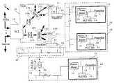
- FIG. 1is a block diagram of a preferred embodiment of a PON/PLC broadband data communications service network, in accordance with the present invention, including PON/PLC HeadEnds coupled to a PON and to a conventional electrical power distribution network and PLC residential gateways at respective end user facilities also coupled to the power distribution network.
- FIG. 2is a block diagram of a preferred embodiment of a PLC HeadEnd as connected in the PON/PLC network shown in FIG. 1 .
- FIG. 3is a block diagram of another preferred embodiment of a PON/PLC broadband data communications service network, in accordance with the present invention, including PON/PLC HeadEnds coupled to medium voltage and low voltage power conveying media of an electrical power distribution network.
- the present inventionutilizes high speed PLC technology to provide for the delivery of high bandwidth, multi-media information, such as telephony, video-on-demand, broadcast TV, etc., available on a PON directly to an end user facility, such as a home or business, over conventional electrical power conveying media of an existing electrical power distribution network with relative ease and at a moderate installation cost.
- high speed PLC technologyto provide for the delivery of high bandwidth, multi-media information, such as telephony, video-on-demand, broadcast TV, etc., available on a PON directly to an end user facility, such as a home or business, over conventional electrical power conveying media of an existing electrical power distribution network with relative ease and at a moderate installation cost.
- FIG. 1is a PON/PLC broadband data communications service network 10 in accordance with a preferred embodiment of the present invention.
- the network 10includes a passive optical network (“PON”) 12 containing an optical line termination (“OLT”) 14 .
- the OLT 14is coupled to broadband data communications service providers, such as a video server providing video-on-demand, a publicly switched telephone network (“PSTN”), an Internet service provider and a broadcast video and audio service provider, e g., CATV provider, etc., which are external to the PON 12 .
- PSTNpublicly switched telephone network
- the broadband service providersinterface with the PON 12 using conventional interconnections, as suitable.
- Optical fiber cables 16 A and 16 B of the PON 12couple the OLT 14 to passive optical splitters 18 A and 18 B, respectively.
- Each of the splitters 18includes optical signal output ports for coupling to optical fiber cables.
- Optical fiber cables 16 C and 16 Dcouple output ports of the splitters 18 A and 18 B to optical network terminations (“ONT”) 20 A and 20 B, respectively.
- ONToptical network terminations
- conventional electrical data signal transmission media 21 and 23couple PON/PLC HeadEnds 22 and 24 to the ONTs 20 A and 20 B, respectively.
- conventional, low voltage electrical power conveying media 26couples the HeadEnd 22 to low voltage electric power lines 28 of a low voltage (“LV”) electrical power distribution PLC access network 26 .
- the lines 28 of the LV network 26extend into end user facilities, such as homes 30 and 32 .
- Each of the homes 30 and 32includes a PLC residential gateway (“RG”) 34 coupled to the power line wiring 28 within the home, where the RG 34 is, preferably, on the user side of a power meter 36 that is connected to the lines 28 coming into the home.
- RGPLC residential gateway
- conventional, medium voltage (“MV”) electrical power conveying media 41couples the HeadEnd 24 to MV electric power lines 42 of a MV electrical power distribution PLC access network 40 .
- a MV-to-LV transformer 44couples the network 40 to a LV electrical power distribution network 48 including LV power lines 49 .
- the lines 49extend into an end user home 50 .
- the home 50like the homes 30 and 32 , includes a PLC residential gateway 34 coupled to the LV power lines 49 .
- the RG 34 in the home 50preferably, is positioned on the user side of a power meter 36 also coupled to the power lines 49 within the home 50 .
- a PLC bypass unit 45couples the MV lines 42 of the MV network 40 to the LV lines 49 of the LV network 48 .
- the PON 12is a well known optical signal network configuration that typically includes an OLT, optical fibers cables, passive optical splitters and an ONT as described above in connection with FIG. 1 .
- the OLT 14is a well known device including passive optical components, and optionally including active optical signal processing components and electrical signal processing components, which couples high speed broadband data streams provided by broadband data communications service providers, such as a PSTN, Internet service provider, cable television service provider, to optical fiber cables of a PON.
- the optical fiber cables 16are well known in the art, and provide relatively low signal loss over long signal transmission distances, such as distances in excess of 10 miles, and very high, full duplex bandwidth, such as 10 Gb/s.
- the passive optical splitters 18are well known devices in the art that permit point to multi-point full duplex optical communications between ports, which are for coupling to optical fiber cables.
- the ONTsare well known devices used to interconnect optical fiber cables to electrical signal conveying cables, such as Ethernet copper cables.
- Each of the HeadEnds 22 and 24operates to couple PLC signals to and from the power lines to which it is connected and also to protect electronically sensitive PLC processing components therein.
- a preferred embodiment of the HeadEnd 22as connected in the network 10 , is shown in FIG. 2 for purposes of illustration.
- the HeadEnd 22includes a high speed PLC controller 25 , with a processor and memory (not shown), that interfaces with the ONT 20 A via the cable 23 .
- the PLC controller 25is preferably capable of processing signals having data rates associated with data communications services transmitted from a PON directly onto a LV network.
- a PLC transceiver 27couples the PLC controller 25 to a conventional LV PLC coupler 29 , which is for coupling to LV power lines.
- PLC controller 25 and the PLC transceiver 27are described, for example, in U.S. patent application Ser. No. 10/211,033, filed Aug. 2, 2002, assigned to the assignee of this application and incorporated by reference herein.
- the PLC controller 25 and the PLC transceiver 27include high speed data processing capabilities having sufficient bandwidth to maintain the same or substantially the same bandwidth on encoded digital PLC data signals generated at the transceiver 27 as the data bandwidth existing on the optical signals received at the ONT 20 A and whose destination is a device, such as a computer or HDTV decoder, at a downstream end user facility.
- the HeadEnd 22is preferably readily programmable and modular to provide for flexibility with various, different network topologies and service needs. Data encryption, for example, is performed because both optical signal conveying media and PLC media are shared in the network 10 .
- the HeadEnd 24is substantially identical in construction and operation as the HeadEnd 22 , except that the HeadEnd 24 includes a PLC coupler for coupling to a MV power network, rather than an LV network, and the PLC controller and PLC transceiver combination can process signals having data rates associated with broadband service transmission from a PON onto a MV network, which usually are much higher than those expected to be transmitted onto an LV network from a PON.
- the RGis a conventional PLC gateway, and preferably is a PLC gateway having the features described in U.S. patent application Ser. No. 10/211,033.
- the RGis installed at an end user facility, preferably by plugging into the LV power lines in the facility, to permit an end user in the facility to receive and process the PLC signals available on the LV power lines of the LV network.
- the bypass unit 45is a well known, conventional prior art PLC apparatus that provides PLC data communications signal connectivity between electronic devices in a MV power distribution network and electronic devices in a LV power distribution network.
- the bypass unit 45can constitute a PLC repeater as described in U.S. patent application Ser. No. 10/211,033.
- high speed, broadband data communications service providersgenerate and make available high speed, broadband downstream data streams modulated on optical carrier signals.
- the OLT 14receives these broadband optical signals, optionally processes them as may be required, and then couples the broadband optical signals directly to the optical fiber cables 16 of the PON 12 .
- the electrical signalsare suitably converted to broadband optical signals at the OLT 14 , as is conventional in the art.
- the downstream broadband optical signalsare conveyed over the cables 16 A and 16 B of the PON 12 to the passive splitters 18 A and 18 B, and then distributed over the cables 16 C and 16 D to the ONTs 20 A and 20 B, respectively.
- the ONTs 20 A and 20 Bconvert the broadband, optical signals into electrical signals that are modulated with the downstream broadband high speed data used to modulate the optical signals. These data modulated electrical signals are then conveyed over the cables 21 and 23 to the HeadEnds 22 and 24 , respectively.
- the PLC controller 25performs suitable data and signal processing operations on the received electrical signals and generates digitally encoded data that the PLC transceiver 27 uses to generate digitally encoded downstream broadband PLC signals, including suitable protocol encoding such as, for example, data encryption.
- the PLC transceiver 27 at each of the HeadEndsgenerates downstream broadband PLC signals having the same or substantially the same data bandwidth as corresponding downstream broadband optical signals received at the respective ONTs.
- the PLC transceiver 27transmits the downstream broadband PLC signals, via the coupler 29 and the LV line 26 , onto the LV lines 28 of the network 26 .
- the RG 34 in each of the homes 30 and 32receives and processes the downstream broadband PLC signals to provide for access to broadband services, such as by a computer or video-on-demand decoder.
- the combination of high speed PON technology with high speed PLC technology at the HeadEndprovides that multiple, high bandwidth services can be delivered directly to an end user facility.
- the RG 34transmits upstream digitally encoded PLC data over the lines 28 for receipt at the HeadEnd 22 .
- the HeadEnd 22converts the PLC signals, which include protocol encoding, into data modulated optical signals, which are then conveyed over the optical fiber cables of the PON 12 to a desired destination, such as a PSTN.
- the HeadEnd 24operates substantially identically to the HeadEnd 22 , except that the HeadEnd 24 transmits higher data rate, broadband downstream PLC data signals, via the line 41 , onto the lines 42 of the MV network 40 .
- the bypass unit 45operates to couple the PLC signals transmitted on the lines 42 of the MV network 40 to the lines 49 of the LV network 48 .
- the downstream PLC signals on the network 48are distributed to the RG 34 of the home 50 in a similar manner as described above for the LV network 26 .
- Upstream signal transmissionis performed in a manner similar to that described above for the network 26 , except that the PLC signals are transmitted through the intermediate MV network 40 and MV lines before reaching the HeadEnd 24 .
- FIG. 3illustrates another preferred embodiment of a PON/PLC data communications service network 60 in accordance with the present invention.
- the network 60includes a high voltage (“HV”) electrical power distribution network 62 , MV electrical power distribution networks 64 and 66 and LV electrical power distribution networks 68 , 70 , 72 and 74 .
- HVhigh voltage
- Conventional, high voltage/medium voltage transformers 76couple the HV network 62 to the MV networks 64 and 66 , respectively.
- a medium voltage/low voltage transformer 44couples the MV network 64 to each of the LV networks 68 and 70 and the MV network 66 to each of the LV networks 72 and 74 .
- a PON/PLC HeadEnd 24is coupled to MV power lines 67 of the MV network 64 and a PON/PLC HeadEnd 78 is coupled to LV power lines 69 of the LV network 68 .
- bypass units 45couple the MV power lines 67 of the network 66 to LV power lines 73 and 75 of the LV networks 72 and 74 , respectively.
- the HeadEnd 78is preferably identical, or substantially identical, to the HeadEnds 22 in construction and operation and is for coupling to an ONT of a PON.
- Each of the networks 68 , 70 , 72 and 74includes end user facilities 80 which are coupled to the respective LV power lines of the LV networks.
- the facilities 80can include residential gateways (not shown) for coupling to the LV power lines and providing PLC data communications capabilities.
- a PLC HeadEndis installed at a specific location of a PON based on the PON network topology, the broadband service subscription pattern at end user facilities, availability of a PON connection, availability of a suitable building to house HeadEnd equipment, availability of suitable content on the segment of the PON at interest, access to MV or LV power lines for establishing PLC connections, and the maximum distance between the ONT and an end user facility, such that PLC repeaters would be required.
- the LV network topologyis determined, for example, by the number of end user facilities, such as homes or businesses, connected to a single MV/LV transformer, which varies throughout North American and is different in Europe and Asia.
- an RGis installed on a LV network, such as the network 68 , to provide that that LV network 68 and an in-home communications network in an end user facility 80 share the same network.
- the elements of the LV network and the in-home networkare isolated from one another through the use of encryption and addressing.
- communication end-points within a homesuch an HDTV decoder or computer, are assigned unique in-home addresses, and elements on the LV network are assigned addresses from another pool of unique access addresses. Encryption insures that the data on any common medium is useable only at the appropriate consumers at an end user facility.
- the RGis installed to act as a gateway from a LV access network into an in-home network of an end user facility.
- the present inventionprovides for distribution of high speed, broadband data to an end user from an ONT of a PON using existing, electrical power conveying media of an electrical power distribution network that extends from an end user facility to or near the ONT.
- the cost of accessing, and distributing onto a PLC network, the broadband data services available on the PONis relatively low because the electrical power conveying media, such as MV or LV power lines over which the broadband PLC data signals are to be conveyed, are already existing and the cost of the PON/PLC HeadEnd equipment is low.
- the need to install only the PLC/PON HeadEnd to effectively extend the broadband services on the PON into an end user facilityeliminates the costly need to install cables or other types of equipment.
- the present inventionmakes available ample communications bandwidth for all desired services provided on a PON.
Landscapes
- Engineering & Computer Science (AREA)
- Computer Networks & Wireless Communication (AREA)
- Signal Processing (AREA)
- Power Engineering (AREA)
- Cable Transmission Systems, Equalization Of Radio And Reduction Of Echo (AREA)
- Small-Scale Networks (AREA)
Abstract
Description
Claims (15)
Priority Applications (1)
| Application Number | Priority Date | Filing Date | Title |
|---|---|---|---|
| US10/309,567US6844809B2 (en) | 2001-12-04 | 2002-12-04 | Passive optical network backhaul for powerline communications |
Applications Claiming Priority (2)
| Application Number | Priority Date | Filing Date | Title |
|---|---|---|---|
| US33873601P | 2001-12-04 | 2001-12-04 | |
| US10/309,567US6844809B2 (en) | 2001-12-04 | 2002-12-04 | Passive optical network backhaul for powerline communications |
Publications (2)
| Publication Number | Publication Date |
|---|---|
| US20040004538A1 US20040004538A1 (en) | 2004-01-08 |
| US6844809B2true US6844809B2 (en) | 2005-01-18 |
Family
ID=23325953
Family Applications (1)
| Application Number | Title | Priority Date | Filing Date |
|---|---|---|---|
| US10/309,567Expired - LifetimeUS6844809B2 (en) | 2001-12-04 | 2002-12-04 | Passive optical network backhaul for powerline communications |
Country Status (3)
| Country | Link |
|---|---|
| US (1) | US6844809B2 (en) |
| AU (1) | AU2002365841A1 (en) |
| WO (1) | WO2003049416A1 (en) |
Cited By (41)
| Publication number | Priority date | Publication date | Assignee | Title |
|---|---|---|---|---|
| US20020154000A1 (en)* | 2001-02-14 | 2002-10-24 | Kline Paul A. | Data communication over a power line |
| US20030169155A1 (en)* | 2000-04-14 | 2003-09-11 | Mollenkopf James Douglas | Power line communication system and method of using the same |
| US20030179080A1 (en)* | 2001-12-21 | 2003-09-25 | Mollenkopf James Douglas | Facilitating communication of data signals on electric power systems |
| US20030190110A1 (en)* | 2001-02-14 | 2003-10-09 | Kline Paul A. | Method and apparatus for providing inductive coupling and decoupling of high-frequency, high-bandwidth data signals directly on and off of a high voltage power line |
| US20030234713A1 (en)* | 2002-06-21 | 2003-12-25 | Pridmore Charles Franklin | Power line coupling device and method of using the same |
| US20040001503A1 (en)* | 2002-06-28 | 2004-01-01 | Manter Venitha L. | Apparatus and method for arbitrating among equal priority requests |
| US20040003934A1 (en)* | 2002-06-24 | 2004-01-08 | Cope Leonard David | Power line coupling device and method of using the same |
| US20040110483A1 (en)* | 2002-12-10 | 2004-06-10 | Mollenkopf James Douglas | Power line communication sytem and method |
| US20040113757A1 (en)* | 2002-12-10 | 2004-06-17 | White Melvin Joseph | Power line communication system and method of operating the same |
| US20040113756A1 (en)* | 2002-12-10 | 2004-06-17 | Mollenkopf James Douglas | Device and method for coupling with electrical distribution network infrastructure to provide communications |
| US20040142599A1 (en)* | 2003-01-21 | 2004-07-22 | Cope Leonard D. | Power line coupling device and method of using the same |
| US20040227621A1 (en)* | 2000-04-14 | 2004-11-18 | Cope Leonard D. | Power line communication apparatus and method of using the same |
| US20040227622A1 (en)* | 2003-05-13 | 2004-11-18 | Giannini Paul M. | Device and method for communicating data signals through multiple power line conductors |
| US20040246107A1 (en)* | 2001-02-14 | 2004-12-09 | Current Technologies, L.L.C. | Power line communication system and method of using the same |
| US20040268160A1 (en)* | 2003-06-30 | 2004-12-30 | Atkinson Douglas A. | Power adapter and broadband line extender system and method |
| US20050100043A1 (en)* | 2000-04-19 | 2005-05-12 | Serconet Ltd | Network combining wired and non-wired segments |
| US20050168326A1 (en)* | 2002-12-10 | 2005-08-04 | Current Technologies, Llc | Power line repeater system and method |
| US20050206507A1 (en)* | 2000-04-14 | 2005-09-22 | Kline Paul A | Power line communication system and method |
| US20060097573A1 (en)* | 2004-10-26 | 2006-05-11 | Gidge Brett D | Power line communications system and method of operating the same |
| WO2006104630A1 (en)* | 2005-03-02 | 2006-10-05 | John Jamieson | An inverted passive optical network/inverted passive electrical network (ipon/ipen) based data fusion and synchronization system |
| US20060221995A1 (en)* | 2005-04-04 | 2006-10-05 | Berkman William H | Multi-function modem device |
| US7132819B1 (en) | 2002-11-12 | 2006-11-07 | Current Technologies, Llc | Floating power supply and method of using the same |
| US20060255930A1 (en)* | 2005-05-12 | 2006-11-16 | Berkman William H | Power line communications system and method |
| US20060291575A1 (en)* | 2003-07-03 | 2006-12-28 | Berkman William H | Power Line Communication System and Method |
| US20070054622A1 (en)* | 2005-09-02 | 2007-03-08 | Berkman William H | Hybrid power line wireless communication system |
| US20070153836A1 (en)* | 2003-03-13 | 2007-07-05 | Serconet, Ltd. | Telephone system having multiple distinct sources and accessories therefor |
| US20070201494A1 (en)* | 2002-06-07 | 2007-08-30 | Heng Lou | Last Leg Utility Grid High-Speed Data Communication Network Having Virtual Local Area Network Functionality |
| US7265664B2 (en) | 2005-04-04 | 2007-09-04 | Current Technologies, Llc | Power line communications system and method |
| US20080280569A1 (en)* | 2004-05-06 | 2008-11-13 | Serconet Ltd. | System and Method for Carrying a Wireless Based Signal Over Wiring |
| US20090125963A1 (en)* | 2005-04-18 | 2009-05-14 | S.I.Sv.El. S.P.A. | System for establishing a connection between a service centre and a plurality of devices for the reception of television signal |
| US20090198795A1 (en)* | 2004-01-13 | 2009-08-06 | Yehuda Binder | Information device |
| US7675897B2 (en) | 2005-09-06 | 2010-03-09 | Current Technologies, Llc | Power line communications system with differentiated data services |
| US7764943B2 (en) | 2006-03-27 | 2010-07-27 | Current Technologies, Llc | Overhead and underground power line communication system and method using a bypass |
| US7813451B2 (en) | 2006-01-11 | 2010-10-12 | Mobileaccess Networks Ltd. | Apparatus and method for frequency shifting of a wireless signal and systems using frequency shifting |
| US20110018704A1 (en)* | 2009-07-24 | 2011-01-27 | Burrows Zachary M | System, Device and Method for Providing Power Line Communications |
| US8175649B2 (en) | 2008-06-20 | 2012-05-08 | Corning Mobileaccess Ltd | Method and system for real time control of an active antenna over a distributed antenna system |
| US8279058B2 (en) | 2008-11-06 | 2012-10-02 | Current Technologies International Gmbh | System, device and method for communicating over power lines |
| US8594133B2 (en) | 2007-10-22 | 2013-11-26 | Corning Mobileaccess Ltd. | Communication system using low bandwidth wires |
| US8897215B2 (en) | 2009-02-08 | 2014-11-25 | Corning Optical Communications Wireless Ltd | Communication system using cables carrying ethernet signals |
| US9184960B1 (en) | 2014-09-25 | 2015-11-10 | Corning Optical Communications Wireless Ltd | Frequency shifting a communications signal(s) in a multi-frequency distributed antenna system (DAS) to avoid or reduce frequency interference |
| US9338823B2 (en) | 2012-03-23 | 2016-05-10 | Corning Optical Communications Wireless Ltd | Radio-frequency integrated circuit (RFIC) chip(s) for providing distributed antenna system functionalities, and related components, systems, and methods |
Families Citing this family (18)
| Publication number | Priority date | Publication date | Assignee | Title |
|---|---|---|---|---|
| US20040150750A1 (en)* | 2003-01-31 | 2004-08-05 | Qwest Communications International Inc. | Systems and methods for monitoring visual information |
| US20040150748A1 (en)* | 2003-01-31 | 2004-08-05 | Qwest Communications International Inc. | Systems and methods for providing and displaying picture-in-picture signals |
| US7921443B2 (en) | 2003-01-31 | 2011-04-05 | Qwest Communications International, Inc. | Systems and methods for providing video and data services to a customer premises |
| US8490129B2 (en) | 2003-01-31 | 2013-07-16 | Qwest Communications International Inc. | Methods, systems and apparatus for selectively distributing urgent public information |
| US10142023B2 (en) | 2003-01-31 | 2018-11-27 | Centurylink Intellectual Property Llc | Antenna system and methods for wireless optical network termination |
| US8112449B2 (en)* | 2003-08-01 | 2012-02-07 | Qwest Communications International Inc. | Systems and methods for implementing a content object access point |
| US8434115B1 (en)* | 2004-06-03 | 2013-04-30 | Verizon Services Corp. | Multi-component ONT power supply |
| US7627402B2 (en)* | 2005-10-21 | 2009-12-01 | Current Technologies, Llc | Device and method for designing power line communication system networks |
| CN101317350B (en)* | 2005-11-29 | 2012-07-04 | Ls电线有限公司 | Power line communication system using hybrid optical fiber coaxial cable network and communication device used in the above system |
| US8178997B2 (en) | 2009-06-15 | 2012-05-15 | Google Inc. | Supplying grid ancillary services using controllable loads |
| US9325416B2 (en)* | 2010-07-30 | 2016-04-26 | At&T Intellectual Property I, L.P. | Network interface device for optical premises signals and networks |
| US9686010B2 (en)* | 2011-12-22 | 2017-06-20 | Sterlite Networks Limited | System and method for providing resilience in communication networks |
| US9009500B1 (en) | 2012-01-18 | 2015-04-14 | Google Inc. | Method of correlating power in a data center by fitting a function to a plurality of pairs of actual power draw values and estimated power draw values determined from monitored CPU utilization of a statistical sample of computers in the data center |
| JP2015023505A (en)* | 2013-07-22 | 2015-02-02 | 国立大学法人愛媛大学 | Plc signal relay system |
| EP3107219B1 (en)* | 2015-06-18 | 2018-12-12 | Power Plus Communications AG | System and method for redundant connection to a backbone network and uplink nodes which can be used in this system |
| EP3301938A1 (en)* | 2016-09-28 | 2018-04-04 | Thomson Licensing | Method, system and apparatus for granting location-based credentials to a device |
| US11356756B1 (en) | 2021-04-05 | 2022-06-07 | Commonwealth Edison Company | Passive optical network for utility infrastructure resiliency |
| CN116545475B (en)* | 2023-07-06 | 2023-09-08 | 北京煜邦电力技术股份有限公司 | Method and system for optimizing power carrier signal indicated by optical signal |
Citations (10)
| Publication number | Priority date | Publication date | Assignee | Title |
|---|---|---|---|---|
| US3900842A (en)* | 1973-03-29 | 1975-08-19 | Automated Technology Corp | Remote automatic meter reading and control system |
| US4204195A (en)* | 1977-05-23 | 1980-05-20 | General Electric Company | Meter terminal unit for use in automatic remote meter reading and control system |
| US4709339A (en) | 1983-04-13 | 1987-11-24 | Fernandes Roosevelt A | Electrical power line parameter measurement apparatus and systems, including compact, line-mounted modules |
| US4714912A (en) | 1986-12-31 | 1987-12-22 | General Electric Company | Single-conductor power line communications system |
| US5630204A (en) | 1995-05-01 | 1997-05-13 | Bell Atlantic Network Services, Inc. | Customer premise wireless distribution of broad band signals and two-way communication of control signals over power lines |
| US5815295A (en)* | 1993-03-11 | 1998-09-29 | Lucent Technologies Inc. | Optical communication system with improved maintenance capabilities |
| US6278357B1 (en) | 1999-02-04 | 2001-08-21 | Electric Power Research Institute, Inc. | Apparatus and method for implementing digital communications on a power line |
| US6404348B1 (en)* | 1999-02-11 | 2002-06-11 | Power Quality Consultants, Inc. | Modular power quality monitoring device |
| US6587739B1 (en)* | 2000-09-29 | 2003-07-01 | Sunbeam Products, Inc. | Appliance communication and control system and appliances for use in same |
| US6744824B1 (en)* | 1999-11-05 | 2004-06-01 | Alcatel | Multiple access method, devices for performing this method and communications systems using these methods |
- 2002
- 2002-12-04USUS10/309,567patent/US6844809B2/ennot_activeExpired - Lifetime
- 2002-12-04WOPCT/US2002/038832patent/WO2003049416A1/ennot_activeApplication Discontinuation
- 2002-12-04AUAU2002365841Apatent/AU2002365841A1/ennot_activeAbandoned
Patent Citations (10)
| Publication number | Priority date | Publication date | Assignee | Title |
|---|---|---|---|---|
| US3900842A (en)* | 1973-03-29 | 1975-08-19 | Automated Technology Corp | Remote automatic meter reading and control system |
| US4204195A (en)* | 1977-05-23 | 1980-05-20 | General Electric Company | Meter terminal unit for use in automatic remote meter reading and control system |
| US4709339A (en) | 1983-04-13 | 1987-11-24 | Fernandes Roosevelt A | Electrical power line parameter measurement apparatus and systems, including compact, line-mounted modules |
| US4714912A (en) | 1986-12-31 | 1987-12-22 | General Electric Company | Single-conductor power line communications system |
| US5815295A (en)* | 1993-03-11 | 1998-09-29 | Lucent Technologies Inc. | Optical communication system with improved maintenance capabilities |
| US5630204A (en) | 1995-05-01 | 1997-05-13 | Bell Atlantic Network Services, Inc. | Customer premise wireless distribution of broad band signals and two-way communication of control signals over power lines |
| US6278357B1 (en) | 1999-02-04 | 2001-08-21 | Electric Power Research Institute, Inc. | Apparatus and method for implementing digital communications on a power line |
| US6404348B1 (en)* | 1999-02-11 | 2002-06-11 | Power Quality Consultants, Inc. | Modular power quality monitoring device |
| US6744824B1 (en)* | 1999-11-05 | 2004-06-01 | Alcatel | Multiple access method, devices for performing this method and communications systems using these methods |
| US6587739B1 (en)* | 2000-09-29 | 2003-07-01 | Sunbeam Products, Inc. | Appliance communication and control system and appliances for use in same |
Cited By (109)
| Publication number | Priority date | Publication date | Assignee | Title |
|---|---|---|---|---|
| US7307511B2 (en) | 2000-04-14 | 2007-12-11 | Current Technologies, Llc | Power line communication system and method |
| US20030169155A1 (en)* | 2000-04-14 | 2003-09-11 | Mollenkopf James Douglas | Power line communication system and method of using the same |
| US6998962B2 (en) | 2000-04-14 | 2006-02-14 | Current Technologies, Llc | Power line communication apparatus and method of using the same |
| US6965302B2 (en) | 2000-04-14 | 2005-11-15 | Current Technologies, Llc | Power line communication system and method of using the same |
| US20050206507A1 (en)* | 2000-04-14 | 2005-09-22 | Kline Paul A | Power line communication system and method |
| US7245212B2 (en) | 2000-04-14 | 2007-07-17 | Current Technologies, Llc | Power line communication apparatus and method of using the same |
| US20050285720A1 (en)* | 2000-04-14 | 2005-12-29 | Cope Leonard D | Power line communication apparatus and method of using the same |
| US20040227621A1 (en)* | 2000-04-14 | 2004-11-18 | Cope Leonard D. | Power line communication apparatus and method of using the same |
| US20100135479A1 (en)* | 2000-04-19 | 2010-06-03 | Mosaid Technologies Incorporated | Network combining wired and non-wired segments |
| US8873575B2 (en) | 2000-04-19 | 2014-10-28 | Conversant Intellectual Property Management Incorporated | Network combining wired and non-wired segments |
| US7876767B2 (en) | 2000-04-19 | 2011-01-25 | Mosaid Technologies Incorporated | Network combining wired and non-wired segments |
| US20100135480A1 (en)* | 2000-04-19 | 2010-06-03 | Mosaid Technologies Incorporated | Network combining wired and non-wired segments |
| US8289991B2 (en) | 2000-04-19 | 2012-10-16 | Mosaid Technologies Incorporated | Network combining wired and non-wired segments |
| US8848725B2 (en) | 2000-04-19 | 2014-09-30 | Conversant Intellectual Property Management Incorporated | Network combining wired and non-wired segments |
| US20100135191A1 (en)* | 2000-04-19 | 2010-06-03 | Mosaid Technologies Incorporated | Network Combining Wired and Non-Wired Segments |
| US20050100043A1 (en)* | 2000-04-19 | 2005-05-12 | Serconet Ltd | Network combining wired and non-wired segments |
| US8867506B2 (en) | 2000-04-19 | 2014-10-21 | Conversant Intellectual Property Management Incorporated | Network combining wired and non-wired segments |
| US7933297B2 (en) | 2000-04-19 | 2011-04-26 | Mosaid Technologies Incorporated | Network combining wired and non-wired segments |
| US7633966B2 (en) | 2000-04-19 | 2009-12-15 | Mosaid Technologies Incorporated | Network combining wired and non-wired segments |
| US8873586B2 (en) | 2000-04-19 | 2014-10-28 | Conversant Intellectual Property Management Incorporated | Network combining wired and non-wired segments |
| US8982904B2 (en) | 2000-04-19 | 2015-03-17 | Conversant Intellectual Property Management Inc. | Network combining wired and non-wired segments |
| US20050232299A1 (en)* | 2000-04-19 | 2005-10-20 | Serconet, Ltd. | Network combining wired and non-wired segments |
| US8982903B2 (en) | 2000-04-19 | 2015-03-17 | Conversant Intellectual Property Management Inc. | Network combining wired and non-wired segments |
| US7636373B2 (en) | 2000-04-19 | 2009-12-22 | Mosaid Technologies Incorporated | Network combining wired and non-wired segments |
| US20050254516A1 (en)* | 2000-04-19 | 2005-11-17 | Serconet, Ltd. | Network combining wired and non-wired segments |
| US20050259691A1 (en)* | 2000-04-19 | 2005-11-24 | Serconet Ltd | Network combining wired and non-wired segments |
| US7715441B2 (en) | 2000-04-19 | 2010-05-11 | Mosaid Technologies Incorporated | Network combining wired and non-wired segments |
| US6933835B2 (en) | 2001-02-14 | 2005-08-23 | Current Technologies, Llc | Data communication over a power line |
| US20050213874A1 (en)* | 2001-02-14 | 2005-09-29 | Kline Paul A | Power line communication system and method |
| US20030190110A1 (en)* | 2001-02-14 | 2003-10-09 | Kline Paul A. | Method and apparatus for providing inductive coupling and decoupling of high-frequency, high-bandwidth data signals directly on and off of a high voltage power line |
| US20020154000A1 (en)* | 2001-02-14 | 2002-10-24 | Kline Paul A. | Data communication over a power line |
| US20040246107A1 (en)* | 2001-02-14 | 2004-12-09 | Current Technologies, L.L.C. | Power line communication system and method of using the same |
| US7046882B2 (en) | 2001-02-14 | 2006-05-16 | Current Technologies, Llc | Power line communication system and method |
| US7187276B2 (en) | 2001-02-14 | 2007-03-06 | Current Technologies, Llc | Power line communication system and method of using the same |
| US6950567B2 (en) | 2001-02-14 | 2005-09-27 | Current Technologies, Llc | Method and apparatus for providing inductive coupling and decoupling of high-frequency, high-bandwidth data signals directly on and off of a high voltage power line |
| US20100102987A1 (en)* | 2001-05-18 | 2010-04-29 | Heng Lou | Power Line Communication Device having Virtual Local Area Network Functionality |
| US20030179080A1 (en)* | 2001-12-21 | 2003-09-25 | Mollenkopf James Douglas | Facilitating communication of data signals on electric power systems |
| US7053756B2 (en) | 2001-12-21 | 2006-05-30 | Current Technologies, Llc | Facilitating communication of data signals on electric power systems |
| US7664117B2 (en) | 2002-06-07 | 2010-02-16 | Current Grid, Llc | Last leg utility grid high-speed data communication network having virtual local area network functionality |
| US20070201494A1 (en)* | 2002-06-07 | 2007-08-30 | Heng Lou | Last Leg Utility Grid High-Speed Data Communication Network Having Virtual Local Area Network Functionality |
| US7102478B2 (en) | 2002-06-21 | 2006-09-05 | Current Technologies, Llc | Power line coupling device and method of using the same |
| US20030234713A1 (en)* | 2002-06-21 | 2003-12-25 | Pridmore Charles Franklin | Power line coupling device and method of using the same |
| US7224243B2 (en) | 2002-06-24 | 2007-05-29 | Current Technologies, Llc | Power line coupling device and method of using the same |
| US6982611B2 (en) | 2002-06-24 | 2006-01-03 | Current Technologies, Llc | Power line coupling device and method of using the same |
| US20060012449A1 (en)* | 2002-06-24 | 2006-01-19 | Cope Leonard D | Power line coupling device and method of using the same |
| US20040003934A1 (en)* | 2002-06-24 | 2004-01-08 | Cope Leonard David | Power line coupling device and method of using the same |
| US20040001503A1 (en)* | 2002-06-28 | 2004-01-01 | Manter Venitha L. | Apparatus and method for arbitrating among equal priority requests |
| US7132819B1 (en) | 2002-11-12 | 2006-11-07 | Current Technologies, Llc | Floating power supply and method of using the same |
| US20040110483A1 (en)* | 2002-12-10 | 2004-06-10 | Mollenkopf James Douglas | Power line communication sytem and method |
| US20040113756A1 (en)* | 2002-12-10 | 2004-06-17 | Mollenkopf James Douglas | Device and method for coupling with electrical distribution network infrastructure to provide communications |
| US6980090B2 (en) | 2002-12-10 | 2005-12-27 | Current Technologies, Llc | Device and method for coupling with electrical distribution network infrastructure to provide communications |
| US7701325B2 (en) | 2002-12-10 | 2010-04-20 | Current Technologies, Llc | Power line communication apparatus and method of using the same |
| US7250848B2 (en) | 2002-12-10 | 2007-07-31 | Current Technologies, Llc | Power line communication apparatus and method of using the same |
| US20050273282A1 (en)* | 2002-12-10 | 2005-12-08 | Mollenkopf James D | Power line communication system and method |
| US6965303B2 (en) | 2002-12-10 | 2005-11-15 | Current Technologies, Llc | Power line communication system and method |
| US20050168326A1 (en)* | 2002-12-10 | 2005-08-04 | Current Technologies, Llc | Power line repeater system and method |
| US8198999B2 (en) | 2002-12-10 | 2012-06-12 | Current Technologies, Llc | Power line communication system and method of operating the same |
| US7301440B2 (en)* | 2002-12-10 | 2007-11-27 | Current Technologies, Llc | Power line communication system and method |
| US20090134996A1 (en)* | 2002-12-10 | 2009-05-28 | White Ii Melvin Joseph | Power Line Communication System and Method of Operating the Same |
| US7224272B2 (en) | 2002-12-10 | 2007-05-29 | Current Technologies, Llc | Power line repeater system and method |
| US20040113757A1 (en)* | 2002-12-10 | 2004-06-17 | White Melvin Joseph | Power line communication system and method of operating the same |
| US20060038662A1 (en)* | 2002-12-10 | 2006-02-23 | White Melvin J Ii | Power line communication system and method of operating the same |
| US6980091B2 (en) | 2002-12-10 | 2005-12-27 | Current Technologies, Llc | Power line communication system and method of operating the same |
| US7466225B2 (en) | 2002-12-10 | 2008-12-16 | Current Technologies, Llc | Power line communication system and method of operating the same |
| US20040142599A1 (en)* | 2003-01-21 | 2004-07-22 | Cope Leonard D. | Power line coupling device and method of using the same |
| US7046124B2 (en) | 2003-01-21 | 2006-05-16 | Current Technologies, Llc | Power line coupling device and method of using the same |
| US20070153836A1 (en)* | 2003-03-13 | 2007-07-05 | Serconet, Ltd. | Telephone system having multiple distinct sources and accessories therefor |
| US20040227622A1 (en)* | 2003-05-13 | 2004-11-18 | Giannini Paul M. | Device and method for communicating data signals through multiple power line conductors |
| US7075414B2 (en) | 2003-05-13 | 2006-07-11 | Current Technologies, Llc | Device and method for communicating data signals through multiple power line conductors |
| US7194639B2 (en)* | 2003-06-30 | 2007-03-20 | Tellabs Vienna, Inc. | Power adapter and broadband line extender system and method |
| US20040268160A1 (en)* | 2003-06-30 | 2004-12-30 | Atkinson Douglas A. | Power adapter and broadband line extender system and method |
| US20060291575A1 (en)* | 2003-07-03 | 2006-12-28 | Berkman William H | Power Line Communication System and Method |
| US20110009077A1 (en)* | 2004-01-13 | 2011-01-13 | May Patents Ltd. | Information device |
| US20090198795A1 (en)* | 2004-01-13 | 2009-08-06 | Yehuda Binder | Information device |
| US8325759B2 (en) | 2004-05-06 | 2012-12-04 | Corning Mobileaccess Ltd | System and method for carrying a wireless based signal over wiring |
| US20080280569A1 (en)* | 2004-05-06 | 2008-11-13 | Serconet Ltd. | System and Method for Carrying a Wireless Based Signal Over Wiring |
| US8325693B2 (en) | 2004-05-06 | 2012-12-04 | Corning Mobileaccess Ltd | System and method for carrying a wireless based signal over wiring |
| US7321291B2 (en) | 2004-10-26 | 2008-01-22 | Current Technologies, Llc | Power line communications system and method of operating the same |
| US20060097573A1 (en)* | 2004-10-26 | 2006-05-11 | Gidge Brett D | Power line communications system and method of operating the same |
| GB2438355A (en)* | 2005-03-02 | 2007-11-21 | John Jamieson | An inverted passive optical network/inverted passive electrical network (iPON/iPEN) based data fusion and synchronization system |
| US8018954B2 (en) | 2005-03-02 | 2011-09-13 | 3 Phoenix, Inc. | Inverted passive optical network/inverted passive electrical network (iPON/iPEN) based data fusion and synchronization system |
| WO2006104630A1 (en)* | 2005-03-02 | 2006-10-05 | John Jamieson | An inverted passive optical network/inverted passive electrical network (ipon/ipen) based data fusion and synchronization system |
| US20070291777A1 (en)* | 2005-03-02 | 2007-12-20 | 3 Phoenix, Inc. | Inverted Passive Optical Network/inverted Passive Electrical Network (iPON/iPEN) Based Data Fusion and Synchronization System |
| GB2438355B (en)* | 2005-03-02 | 2010-01-06 | John Jamieson | A communication system and a method of providing communication services |
| US7265664B2 (en) | 2005-04-04 | 2007-09-04 | Current Technologies, Llc | Power line communications system and method |
| US7450001B2 (en) | 2005-04-04 | 2008-11-11 | Current Technologies, Llc | Power line communications system and method |
| US20070268124A1 (en)* | 2005-04-04 | 2007-11-22 | Berkman William H | Power Line Communications System and Method |
| US20060221995A1 (en)* | 2005-04-04 | 2006-10-05 | Berkman William H | Multi-function modem device |
| US7856032B2 (en)* | 2005-04-04 | 2010-12-21 | Current Technologies, Llc | Multi-function modem device |
| US20090125963A1 (en)* | 2005-04-18 | 2009-05-14 | S.I.Sv.El. S.P.A. | System for establishing a connection between a service centre and a plurality of devices for the reception of television signal |
| US20060255930A1 (en)* | 2005-05-12 | 2006-11-16 | Berkman William H | Power line communications system and method |
| US20070054622A1 (en)* | 2005-09-02 | 2007-03-08 | Berkman William H | Hybrid power line wireless communication system |
| US7675897B2 (en) | 2005-09-06 | 2010-03-09 | Current Technologies, Llc | Power line communications system with differentiated data services |
| US8184681B2 (en) | 2006-01-11 | 2012-05-22 | Corning Mobileaccess Ltd | Apparatus and method for frequency shifting of a wireless signal and systems using frequency shifting |
| US20110206088A1 (en)* | 2006-01-11 | 2011-08-25 | Mobileaccess Networks Ltd. | Apparatus and method for frequency shifting of a wireless signal and systems using frequency shifting |
| US7813451B2 (en) | 2006-01-11 | 2010-10-12 | Mobileaccess Networks Ltd. | Apparatus and method for frequency shifting of a wireless signal and systems using frequency shifting |
| US7764943B2 (en) | 2006-03-27 | 2010-07-27 | Current Technologies, Llc | Overhead and underground power line communication system and method using a bypass |
| US8594133B2 (en) | 2007-10-22 | 2013-11-26 | Corning Mobileaccess Ltd. | Communication system using low bandwidth wires |
| US9813229B2 (en) | 2007-10-22 | 2017-11-07 | Corning Optical Communications Wireless Ltd | Communication system using low bandwidth wires |
| US9549301B2 (en) | 2007-12-17 | 2017-01-17 | Corning Optical Communications Wireless Ltd | Method and system for real time control of an active antenna over a distributed antenna system |
| US8175649B2 (en) | 2008-06-20 | 2012-05-08 | Corning Mobileaccess Ltd | Method and system for real time control of an active antenna over a distributed antenna system |
| US8279058B2 (en) | 2008-11-06 | 2012-10-02 | Current Technologies International Gmbh | System, device and method for communicating over power lines |
| US8897215B2 (en) | 2009-02-08 | 2014-11-25 | Corning Optical Communications Wireless Ltd | Communication system using cables carrying ethernet signals |
| US20110018704A1 (en)* | 2009-07-24 | 2011-01-27 | Burrows Zachary M | System, Device and Method for Providing Power Line Communications |
| US9338823B2 (en) | 2012-03-23 | 2016-05-10 | Corning Optical Communications Wireless Ltd | Radio-frequency integrated circuit (RFIC) chip(s) for providing distributed antenna system functionalities, and related components, systems, and methods |
| US9948329B2 (en) | 2012-03-23 | 2018-04-17 | Corning Optical Communications Wireless, LTD | Radio-frequency integrated circuit (RFIC) chip(s) for providing distributed antenna system functionalities, and related components, systems, and methods |
| US9184960B1 (en) | 2014-09-25 | 2015-11-10 | Corning Optical Communications Wireless Ltd | Frequency shifting a communications signal(s) in a multi-frequency distributed antenna system (DAS) to avoid or reduce frequency interference |
| US9253003B1 (en) | 2014-09-25 | 2016-02-02 | Corning Optical Communications Wireless Ltd | Frequency shifting a communications signal(S) in a multi-frequency distributed antenna system (DAS) to avoid or reduce frequency interference |
| US9515855B2 (en) | 2014-09-25 | 2016-12-06 | Corning Optical Communications Wireless Ltd | Frequency shifting a communications signal(s) in a multi-frequency distributed antenna system (DAS) to avoid or reduce frequency interference |
Also Published As
| Publication number | Publication date |
|---|---|
| WO2003049416A1 (en) | 2003-06-12 |
| US20040004538A1 (en) | 2004-01-08 |
| AU2002365841A1 (en) | 2003-06-17 |
Similar Documents
| Publication | Publication Date | Title |
|---|---|---|
| US6844809B2 (en) | Passive optical network backhaul for powerline communications | |
| US6317884B1 (en) | Video, data and telephony gateway | |
| US6493875B1 (en) | In-home wireless | |
| US20030192053A1 (en) | Method and apparatus for transmitting wireless signals over media | |
| US20030099228A1 (en) | Local area and multimedia network using radio frequency transceivers and coaxial cable | |
| CN1244263A (en) | Photoelectric home area network optical fiber/power plug-in device | |
| US20010036199A1 (en) | Architecture and method for automatic distributed gain control for modem communications over passive multipoint networks | |
| US7068682B2 (en) | Signal distribution within customer premises | |
| US6427237B1 (en) | Network for distributing multimedia signals over a primary signal distribution path | |
| US20050047431A1 (en) | Outlet with analog signal adapter, a method for use thereof and a network using said outlet | |
| US20100103943A1 (en) | Methods and apparatus to provide power over an ethernet-based network to a wide area network access device | |
| AU767634B2 (en) | Method and apparatus for data communication | |
| US20010008534A1 (en) | Digital subscriber line multiplexer | |
| US7313811B1 (en) | Optical conversion device | |
| WO2007064136A1 (en) | Power line communication system and communication device used in the system | |
| EP1238529A2 (en) | Digital subscriber line communication system | |
| WO2000039948A1 (en) | Wiring architecture for providing combined voice and vdsl service to residential buildings | |
| KR100733117B1 (en) | Optical subscriber station device and optical signal distribution method for high speed power line communication | |
| KR100649451B1 (en) | Power line communication system using optical coaxial mixed network and communication equipment used in the power line communication system | |
| KR19990046136A (en) | Internet Subscriber Network | |
| EP1300018A1 (en) | Method and apparatus for transmitting wireless signals over media | |
| KR20080069489A (en) | Adapters and how to configure them | |
| KR20060115468A (en) | PC information TV providing system using home wiring | |
| CA2413118A1 (en) | Local area and multimedia network using radio frequency transceivers and coaxial cable | |
| WO2001011808A1 (en) | Pure optical integrated services network |
Legal Events
| Date | Code | Title | Description |
|---|---|---|---|
| AS | Assignment | Owner name:MILETOS, INC., NEW JERSEY Free format text:BILL OF SALE;ASSIGNOR:ENIKIA, LLC;REEL/FRAME:014608/0163 Effective date:20040323 | |
| AS | Assignment | Owner name:ARKADOS, INC., NEW JERSEY Free format text:MERGER;ASSIGNOR:MILETOS, INC.;REEL/FRAME:015042/0804 Effective date:20040521 | |
| AS | Assignment | Owner name:ENIKIA LLC, NEW JERSEY Free format text:ASSIGNMENT OF ASSIGNORS INTEREST;ASSIGNORS:MANIS, CONSTANTINE N.;LOGVINOV, OLEG;DURFEE, LAWRENCE F.;REEL/FRAME:015443/0245;SIGNING DATES FROM 20031017 TO 20041208 | |
| STCF | Information on status: patent grant | Free format text:PATENTED CASE | |
| REMI | Maintenance fee reminder mailed | ||
| FPAY | Fee payment | Year of fee payment:4 | |
| SULP | Surcharge for late payment | ||
| AS | Assignment | Owner name:BUSHIDO CAPITAL MASTER FUND, LP, NEW YORK Free format text:SECURITY AGREEMENT;ASSIGNOR:ARKADOS, INC.;REEL/FRAME:022416/0682 Effective date:20051228 Owner name:GAMMA OPPOURTUNITY CAPITAL PARTNERS, LP CLASS A, N Free format text:SECURITY AGREEMENT;ASSIGNOR:ARKADOS, INC.;REEL/FRAME:022416/0682 Effective date:20051228 Owner name:GAMMA OPPORTUNITY CAPITAL PARTNERS, LP CLASS C, NE Free format text:SECURITY AGREEMENT;ASSIGNOR:ARKADOS, INC.;REEL/FRAME:022416/0682 Effective date:20051228 Owner name:CRUCIAN TRANSITION, INC., NEW YORK Free format text:SECURITY AGREEMENT;ASSIGNOR:ARKADOS, INC.;REEL/FRAME:022416/0682 Effective date:20051228 Owner name:CARGO HOLDINGS LLC, NEW YORK Free format text:SECURITY AGREEMENT;ASSIGNOR:ARKADOS, INC.;REEL/FRAME:022416/0682 Effective date:20051228 Owner name:TYPALDOS, ANDREAS, NEW YORK Free format text:SECURITY AGREEMENT;ASSIGNOR:ARKADOS, INC.;REEL/FRAME:022416/0682 Effective date:20051228 Owner name:ANDREAS TYPALDOS FAMILY LIMITED PARTNERSHIP, NEW Y Free format text:SECURITY AGREEMENT;ASSIGNOR:ARKADOS, INC.;REEL/FRAME:022416/0682 Effective date:20051228 Owner name:TYPALDOS, KATHRYN, NEW YORK Free format text:SECURITY AGREEMENT;ASSIGNOR:ARKADOS, INC.;REEL/FRAME:022416/0682 Effective date:20051228 Owner name:SOMMER, HERBERT, NEW YORK Free format text:SECURITY AGREEMENT;ASSIGNOR:ARKADOS, INC.;REEL/FRAME:022416/0682 Effective date:20051228 Owner name:SCHNEIDER, JOEL C, NEW YORK Free format text:SECURITY AGREEMENT;ASSIGNOR:ARKADOS, INC.;REEL/FRAME:022416/0682 Effective date:20051228 Owner name:VENDOME, GENNARO, NEW YORK Free format text:SECURITY AGREEMENT;ASSIGNOR:ARKADOS, INC.;REEL/FRAME:022416/0682 Effective date:20051228 Owner name:CARSON, WILLIAM H, TEXAS Free format text:SECURITY AGREEMENT;ASSIGNOR:ARKADOS, INC.;REEL/FRAME:022416/0682 Effective date:20051228 Owner name:BCMF TRUSTEES, LLC, NEW YORK Free format text:SECURITY AGREEMENT;ASSIGNOR:ARKADOS, INC.;REEL/FRAME:022416/0682 Effective date:20051228 Owner name:ACMSPV LLC, NEW YORK Free format text:SECURITY AGREEMENT;ASSIGNOR:ARKADOS, INC.;REEL/FRAME:022416/0682 Effective date:20051228 Owner name:CFRR HOLDINGS LLC, NEW YORK Free format text:SECURITY AGREEMENT;ASSIGNOR:ARKADOS, INC.;REEL/FRAME:022416/0682 Effective date:20051228 Owner name:RABMAN, RALPH, SOUTH AFRICA Free format text:SECURITY AGREEMENT;ASSIGNOR:ARKADOS, INC.;REEL/FRAME:022416/0682 Effective date:20051228 Owner name:PIERCE DIVERSIFIED STRATEGY MASTER FUND LLC SERIES Free format text:SECURITY AGREEMENT;ASSIGNOR:ARKADOS, INC.;REEL/FRAME:022416/0682 Effective date:20051228 Owner name:BUSHIDO CAPITAL MASTER FUND, LP,NEW YORK Free format text:SECURITY AGREEMENT;ASSIGNOR:ARKADOS, INC.;REEL/FRAME:022416/0682 Effective date:20051228 Owner name:GAMMA OPPOURTUNITY CAPITAL PARTNERS, LP CLASS A,NE Free format text:SECURITY AGREEMENT;ASSIGNOR:ARKADOS, INC.;REEL/FRAME:022416/0682 Effective date:20051228 Owner name:GAMMA OPPORTUNITY CAPITAL PARTNERS, LP CLASS C,NEW Free format text:SECURITY AGREEMENT;ASSIGNOR:ARKADOS, INC.;REEL/FRAME:022416/0682 Effective date:20051228 Owner name:CRUCIAN TRANSITION, INC.,NEW YORK Free format text:SECURITY AGREEMENT;ASSIGNOR:ARKADOS, INC.;REEL/FRAME:022416/0682 Effective date:20051228 Owner name:CARGO HOLDINGS LLC,NEW YORK Free format text:SECURITY AGREEMENT;ASSIGNOR:ARKADOS, INC.;REEL/FRAME:022416/0682 Effective date:20051228 Owner name:TYPALDOS, ANDREAS,NEW YORK Free format text:SECURITY AGREEMENT;ASSIGNOR:ARKADOS, INC.;REEL/FRAME:022416/0682 Effective date:20051228 Owner name:ANDREAS TYPALDOS FAMILY LIMITED PARTNERSHIP,NEW YO Free format text:SECURITY AGREEMENT;ASSIGNOR:ARKADOS, INC.;REEL/FRAME:022416/0682 Effective date:20051228 Owner name:TYPALDOS, KATHRYN,NEW YORK Free format text:SECURITY AGREEMENT;ASSIGNOR:ARKADOS, INC.;REEL/FRAME:022416/0682 Effective date:20051228 Owner name:SOMMER, HERBERT,NEW YORK Free format text:SECURITY AGREEMENT;ASSIGNOR:ARKADOS, INC.;REEL/FRAME:022416/0682 Effective date:20051228 Owner name:SCHNEIDER, JOEL C,NEW YORK Free format text:SECURITY AGREEMENT;ASSIGNOR:ARKADOS, INC.;REEL/FRAME:022416/0682 Effective date:20051228 Owner name:VENDOME, GENNARO,NEW YORK Free format text:SECURITY AGREEMENT;ASSIGNOR:ARKADOS, INC.;REEL/FRAME:022416/0682 Effective date:20051228 Owner name:CARSON, WILLIAM H,TEXAS Free format text:SECURITY AGREEMENT;ASSIGNOR:ARKADOS, INC.;REEL/FRAME:022416/0682 Effective date:20051228 Owner name:BCMF TRUSTEES, LLC,NEW YORK Free format text:SECURITY AGREEMENT;ASSIGNOR:ARKADOS, INC.;REEL/FRAME:022416/0682 Effective date:20051228 Owner name:ACMSPV LLC,NEW YORK Free format text:SECURITY AGREEMENT;ASSIGNOR:ARKADOS, INC.;REEL/FRAME:022416/0682 Effective date:20051228 Owner name:CFRR HOLDINGS LLC,NEW YORK Free format text:SECURITY AGREEMENT;ASSIGNOR:ARKADOS, INC.;REEL/FRAME:022416/0682 Effective date:20051228 Owner name:RABMAN, RALPH,SOUTH AFRICA Free format text:SECURITY AGREEMENT;ASSIGNOR:ARKADOS, INC.;REEL/FRAME:022416/0682 Effective date:20051228 | |
| AS | Assignment | Owner name:ARKADOS, INC., NEW JERSEY Free format text:RELEASE BY SECURED PARTY;ASSIGNORS:BUSHIDO CAPITAL MASTER FUND, LP;PIERCE DIVERSIFIED STRATEGY MASTER FUND LLC SERIES BUS;CRUCIAN TRANSITION, INC.;AND OTHERS;REEL/FRAME:026554/0550 Effective date:20110624 Owner name:ARKADOS, INC., NEW JERSEY Free format text:RELEASE BY SECURED PARTY;ASSIGNORS:ANDREAS TYPALDOS FAMILY LIMITED PARTNERSHIP;CARGO HOLDINGS LLC;TYPALDOS, ANDREAS;AND OTHERS;REEL/FRAME:026554/0322 Effective date:20110624 Owner name:THE ARKADOS GROUP (FORMERLY KNOWN AS CDKNET.COM, I Free format text:RELEASE BY SECURED PARTY;ASSIGNORS:ANDREAS TYPALDOS FAMILY LIMITED PARTNERSHIP;CARGO HOLDINGS LLC;TYPALDOS, ANDREAS;AND OTHERS;REEL/FRAME:026554/0322 Effective date:20110624 Owner name:THE ARKADOS GROUP (FORMERLY KNOWN AS CDKNET.COM, I Free format text:RELEASE BY SECURED PARTY;ASSIGNORS:BUSHIDO CAPITAL MASTER FUND, LP;PIERCE DIVERSIFIED STRATEGY MASTER FUND LLC SERIES BUS;CRUCIAN TRANSITION, INC.;AND OTHERS;REEL/FRAME:026554/0550 Effective date:20110624 | |
| REMI | Maintenance fee reminder mailed | ||
| FPAY | Fee payment | Year of fee payment:8 | |
| SULP | Surcharge for late payment | Year of fee payment:7 | |
| SULP | Surcharge for late payment | ||
| FEPP | Fee payment procedure | Free format text:PAT HOLDER NO LONGER CLAIMS SMALL ENTITY STATUS, ENTITY STATUS SET TO UNDISCOUNTED (ORIGINAL EVENT CODE: STOL); ENTITY STATUS OF PATENT OWNER: LARGE ENTITY | |
| FPAY | Fee payment | Year of fee payment:12 |