US6843796B2 - Bone suturing device - Google Patents
Bone suturing deviceDownload PDFInfo
- Publication number
- US6843796B2 US6843796B2US10/005,760US576001AUS6843796B2US 6843796 B2US6843796 B2US 6843796B2US 576001 AUS576001 AUS 576001AUS 6843796 B2US6843796 B2US 6843796B2
- Authority
- US
- United States
- Prior art keywords
- needle
- bone
- needles
- preferred
- boring
- Prior art date
- Legal status (The legal status is an assumption and is not a legal conclusion. Google has not performed a legal analysis and makes no representation as to the accuracy of the status listed.)
- Expired - Lifetime, expires
Links
- 210000000988bone and boneAnatomy0.000titleclaimsabstractdescription217
- 238000005553drillingMethods0.000claimsdescription12
- 238000000034methodMethods0.000abstractdescription32
- 230000007246mechanismEffects0.000description32
- 210000004872soft tissueAnatomy0.000description19
- 230000000284resting effectEffects0.000description18
- 230000033001locomotionEffects0.000description16
- 239000000463materialSubstances0.000description13
- 210000003689pubic boneAnatomy0.000description10
- 230000006378damageEffects0.000description7
- 230000035515penetrationEffects0.000description7
- 239000003381stabilizerSubstances0.000description7
- 210000001519tissueAnatomy0.000description7
- 238000013461designMethods0.000description6
- 239000013598vectorSubstances0.000description5
- 230000009471actionEffects0.000description4
- 238000010276constructionMethods0.000description4
- 239000007787solidSubstances0.000description4
- 230000003321amplificationEffects0.000description3
- 230000000994depressogenic effectEffects0.000description3
- 239000012634fragmentSubstances0.000description3
- 239000007943implantSubstances0.000description3
- 208000014674injuryDiseases0.000description3
- 238000003199nucleic acid amplification methodMethods0.000description3
- 230000008569processEffects0.000description3
- 230000003578releasing effectEffects0.000description3
- 238000012546transferMethods0.000description3
- 230000008878couplingEffects0.000description2
- 238000010168coupling processMethods0.000description2
- 238000005859coupling reactionMethods0.000description2
- 230000009977dual effectEffects0.000description2
- 230000000694effectsEffects0.000description2
- 239000000835fiberSubstances0.000description2
- 238000003780insertionMethods0.000description2
- 230000037431insertionEffects0.000description2
- 238000005259measurementMethods0.000description2
- 230000002829reductive effectEffects0.000description2
- 230000000087stabilizing effectEffects0.000description2
- 229910001220stainless steelInorganic materials0.000description2
- 239000010935stainless steelSubstances0.000description2
- 238000001356surgical procedureMethods0.000description2
- 239000000725suspensionSubstances0.000description2
- 230000026683transductionEffects0.000description2
- 238000010361transductionMethods0.000description2
- 230000008733traumaEffects0.000description2
- 229920000914Metallic fiberPolymers0.000description1
- FAPWRFPIFSIZLT-UHFFFAOYSA-MSodium chlorideChemical compound[Na+].[Cl-]FAPWRFPIFSIZLT-UHFFFAOYSA-M0.000description1
- 208000027418Wounds and injuryDiseases0.000description1
- 230000003213activating effectEffects0.000description1
- 230000004913activationEffects0.000description1
- 230000002411adverseEffects0.000description1
- 230000003190augmentative effectEffects0.000description1
- 230000005540biological transmissionEffects0.000description1
- 230000006835compressionEffects0.000description1
- 238000007906compressionMethods0.000description1
- 238000012937correctionMethods0.000description1
- 239000002537cosmeticSubstances0.000description1
- 238000002316cosmetic surgeryMethods0.000description1
- 230000003247decreasing effectEffects0.000description1
- 239000013013elastic materialSubstances0.000description1
- 238000010304firingMethods0.000description1
- 230000008570general processEffects0.000description1
- 238000002513implantationMethods0.000description1
- 238000000338in vitroMethods0.000description1
- 238000007373indentationMethods0.000description1
- 210000003041ligamentAnatomy0.000description1
- 238000003754machiningMethods0.000description1
- 239000002184metalSubstances0.000description1
- 230000007935neutral effectEffects0.000description1
- HLXZNVUGXRDIFK-UHFFFAOYSA-Nnickel titaniumChemical compound[Ti].[Ti].[Ti].[Ti].[Ti].[Ti].[Ti].[Ti].[Ti].[Ti].[Ti].[Ni].[Ni].[Ni].[Ni].[Ni].[Ni].[Ni].[Ni].[Ni].[Ni].[Ni].[Ni].[Ni].[Ni]HLXZNVUGXRDIFK-UHFFFAOYSA-N0.000description1
- 229910001000nickel titaniumInorganic materials0.000description1
- 230000003287optical effectEffects0.000description1
- 230000000149penetrating effectEffects0.000description1
- 230000007903penetration abilityEffects0.000description1
- 238000003825pressingMethods0.000description1
- 230000004044responseEffects0.000description1
- 230000002441reversible effectEffects0.000description1
- 238000010008shearingMethods0.000description1
- 229920002379silicone rubberPolymers0.000description1
- 210000003625skullAnatomy0.000description1
- 230000001954sterilising effectEffects0.000description1
- 238000004659sterilization and disinfectionMethods0.000description1
- 238000012360testing methodMethods0.000description1
- 230000007704transitionEffects0.000description1
- 210000001215vaginaAnatomy0.000description1
- 230000000007visual effectEffects0.000description1
- 210000000707wristAnatomy0.000description1
Images


Classifications
- A—HUMAN NECESSITIES
- A61—MEDICAL OR VETERINARY SCIENCE; HYGIENE
- A61B—DIAGNOSIS; SURGERY; IDENTIFICATION
- A61B17/00—Surgical instruments, devices or methods
- A61B17/16—Instruments for performing osteoclasis; Drills or chisels for bones; Trepans
- A61B17/1604—Chisels; Rongeurs; Punches; Stamps
- A61B17/1606—Chisels; Rongeurs; Punches; Stamps of forceps type, i.e. having two jaw elements moving relative to each other
- A61B17/1608—Chisels; Rongeurs; Punches; Stamps of forceps type, i.e. having two jaw elements moving relative to each other the two jaw elements being linked to two elongated shaft elements moving longitudinally relative to each other
- A—HUMAN NECESSITIES
- A61—MEDICAL OR VETERINARY SCIENCE; HYGIENE
- A61B—DIAGNOSIS; SURGERY; IDENTIFICATION
- A61B17/00—Surgical instruments, devices or methods
- A61B17/04—Surgical instruments, devices or methods for suturing wounds; Holders or packages for needles or suture materials
- A61B17/06—Needles ; Sutures; Needle-suture combinations; Holders or packages for needles or suture materials
- A61B17/062—Needle manipulators
- A61B17/0625—Needle manipulators the needle being specially adapted to interact with the manipulator, e.g. being ridged to snap fit in a hole of the manipulator
- A—HUMAN NECESSITIES
- A61—MEDICAL OR VETERINARY SCIENCE; HYGIENE
- A61B—DIAGNOSIS; SURGERY; IDENTIFICATION
- A61B17/00—Surgical instruments, devices or methods
- A61B17/16—Instruments for performing osteoclasis; Drills or chisels for bones; Trepans
- A61B17/1604—Chisels; Rongeurs; Punches; Stamps
- A—HUMAN NECESSITIES
- A61—MEDICAL OR VETERINARY SCIENCE; HYGIENE
- A61B—DIAGNOSIS; SURGERY; IDENTIFICATION
- A61B17/00—Surgical instruments, devices or methods
- A61B17/04—Surgical instruments, devices or methods for suturing wounds; Holders or packages for needles or suture materials
- A61B17/0482—Needle or suture guides
- A—HUMAN NECESSITIES
- A61—MEDICAL OR VETERINARY SCIENCE; HYGIENE
- A61B—DIAGNOSIS; SURGERY; IDENTIFICATION
- A61B17/00—Surgical instruments, devices or methods
- A61B17/04—Surgical instruments, devices or methods for suturing wounds; Holders or packages for needles or suture materials
- A61B17/0483—Hand-held instruments for holding sutures
- A—HUMAN NECESSITIES
- A61—MEDICAL OR VETERINARY SCIENCE; HYGIENE
- A61B—DIAGNOSIS; SURGERY; IDENTIFICATION
- A61B17/00—Surgical instruments, devices or methods
- A61B17/16—Instruments for performing osteoclasis; Drills or chisels for bones; Trepans
- A—HUMAN NECESSITIES
- A61—MEDICAL OR VETERINARY SCIENCE; HYGIENE
- A61B—DIAGNOSIS; SURGERY; IDENTIFICATION
- A61B17/00—Surgical instruments, devices or methods
- A61B17/16—Instruments for performing osteoclasis; Drills or chisels for bones; Trepans
- A61B17/1642—Instruments for performing osteoclasis; Drills or chisels for bones; Trepans for producing a curved bore
- A—HUMAN NECESSITIES
- A61—MEDICAL OR VETERINARY SCIENCE; HYGIENE
- A61B—DIAGNOSIS; SURGERY; IDENTIFICATION
- A61B17/00—Surgical instruments, devices or methods
- A61B17/16—Instruments for performing osteoclasis; Drills or chisels for bones; Trepans
- A61B17/17—Guides or aligning means for drills, mills, pins or wires
- A61B17/1796—Guides or aligning means for drills, mills, pins or wires for holes for sutures or flexible wires
- A—HUMAN NECESSITIES
- A61—MEDICAL OR VETERINARY SCIENCE; HYGIENE
- A61B—DIAGNOSIS; SURGERY; IDENTIFICATION
- A61B17/00—Surgical instruments, devices or methods
- A61B17/04—Surgical instruments, devices or methods for suturing wounds; Holders or packages for needles or suture materials
- A61B17/0469—Suturing instruments for use in minimally invasive surgery, e.g. endoscopic surgery
- A61B2017/0472—Multiple-needled, e.g. double-needled, instruments
- A—HUMAN NECESSITIES
- A61—MEDICAL OR VETERINARY SCIENCE; HYGIENE
- A61B—DIAGNOSIS; SURGERY; IDENTIFICATION
- A61B17/00—Surgical instruments, devices or methods
- A61B17/04—Surgical instruments, devices or methods for suturing wounds; Holders or packages for needles or suture materials
- A61B17/06—Needles ; Sutures; Needle-suture combinations; Holders or packages for needles or suture materials
- A61B2017/06052—Needle-suture combinations in which a suture is extending inside a hollow tubular needle, e.g. over the entire length of the needle
- A—HUMAN NECESSITIES
- A61—MEDICAL OR VETERINARY SCIENCE; HYGIENE
- A61B—DIAGNOSIS; SURGERY; IDENTIFICATION
- A61B90/00—Instruments, implements or accessories specially adapted for surgery or diagnosis and not covered by any of the groups A61B1/00 - A61B50/00, e.g. for luxation treatment or for protecting wound edges
- A61B90/06—Measuring instruments not otherwise provided for
- A61B2090/064—Measuring instruments not otherwise provided for for measuring force, pressure or mechanical tension
- A61B2090/065—Measuring instruments not otherwise provided for for measuring force, pressure or mechanical tension for measuring contact or contact pressure
- Y—GENERAL TAGGING OF NEW TECHNOLOGICAL DEVELOPMENTS; GENERAL TAGGING OF CROSS-SECTIONAL TECHNOLOGIES SPANNING OVER SEVERAL SECTIONS OF THE IPC; TECHNICAL SUBJECTS COVERED BY FORMER USPC CROSS-REFERENCE ART COLLECTIONS [XRACs] AND DIGESTS
- Y10—TECHNICAL SUBJECTS COVERED BY FORMER USPC
- Y10T—TECHNICAL SUBJECTS COVERED BY FORMER US CLASSIFICATION
- Y10T408/00—Cutting by use of rotating axially moving tool
- Y10T408/96—Miscellaneous
Definitions
- the present inventionrelates to forming channels through bones and especially to threading such channels with sutures.
- Attaching a suture to a boneis a task that is well known in the art of surgery.
- a common solutionis to screw a threaded screw into the bone.
- screwdrivers used to perform this taskare often complex and/or expensive.
- Another solution described for example in U.S. Pat. No. 5,520,700 to Beyar et al., the disclosure of which is incorporated herein by reference,is to insert a threaded bone anchor into the bone.
- a disadvantage of both this and the previous techniquesis that a hard foreign body is left implanted in the body. In general, it is desirable to leave as small an amount as possible of foreign material in the human bone. Additionally, screws and bone anchors typically cause a considerable amount of trauma to the bone, which trauma is undesirable.
- PCT publication WO 97/47246describes a suture insertion device that purports to form channels in a bone for the suture to be tied through the channel.
- the needles suggested in this PCT publication for forming a curved channelare either curved or are super-elastic needles that are supposed to curve inside the bone. In general, these needles are inserted into the bone at a perpendicular thereto by pushing them along a suitable bore.
- An alternative method suggestedis drilling using a rotary drill, along a curved path. However, it is noted that drills usually damage a large amount of bone.
- Biolectron, Inc.provides a device (“CurvTek”) which drills along a curved path in a bone, from two ends of the path, using air-pressure powered rotary drill bits.
- An object of some preferred embodiments of the inventionis to provide a method of fixing a suture to a bone, while causing a minimum of damage to the bone and/or a minimum of implanted foreign objects, especially a minimum of implanted hard objects.
- An aspect of some preferred embodiments of the inventionrelates to mounting a bone-boring needle on a rotary hinge.
- One desirable result of this structureis that transfer of power to the tip of the needle is more efficient.
- Another desirable resultis a simpler construction.
- Another desirable resultis obtaining a more controllable and/or known path inside the bone. It should be noted that some or all of these desirable results (and others described herein) might not be achieved in some preferred embodiment of the invention.
- An aspect of some preferred embodiments of the inventionrelates to boring a channel through a bone using two opposing needles.
- One desirable resultis that more of the force applied to the needles is utilized to bore into the bone, rather than for pushing the needle away from the bone.
- the needlesare in a same plane.
- the needlesare curved.
- the needlesare straight.
- an anvilwhich does not enter the bone, but which provides a contra-force to the other needle replaces one of the needles.
- An aspect of some preferred embodiments of the inventionrelates to a cross-section of needles used for boring in bone.
- the needlesare smooth.
- the needlesare grooved.
- the cross-sectionis circular, however, other cross-sections, such as flat-rectangular, triangular and ellipsoid may also be provided.
- the cross-sectional shapevaries along the length of the needle, for example providing a spiraling cross-section.
- An aspect of some preferred embodiments of the inventionrelates to inserting a bone-boring needle into a bone at an angle substantially different from a perpendicular.
- two or more needlesare provided, facing each other and applying force to the bone at the same time, in opposite directions and having a main force vector pointed towards a common point.
- the resulting pathis not a full half circle, but only an arc of a circle.
- a path which is more than a half circlemay be bored.
- an arc pathis preferred, in some preferred embodiments of the invention other curves may be formed.
- the curvesare preferably planar, in some embodiments of the invention, the curves are non-planar, for example being bi-planar (each of two halves of the curve in a different plane).
- An aspect of some preferred embodiments of the inventionrelates to a method of boring a hole in a bone in which a cortex of a bone is penetrated using a drill and a medulla of the bone is bored using one or two needles.
- the drillsare straight and the needles are curved, so the needles meet inside the bone.
- the drillsdo not move other that rotation around their axis.
- the drillstravel along a curved path, for example one defined by the needles.
- the needlesare straight.
- the needles(and, optionally, the thread) pass through the drill bits.
- An aspect of some preferred embodiments of the inventionrelates to a drill bit for drilling in bone that includes an aperture for the extension of a needle through the aperture in the drill bit.
- the apertureis in the side of the drill bit.
- the drill bitis mounted in a drill head that mechanically synchronizes the angular position of the drill bit and the extension of the needle.
- the needlesadvance, the drill bits are released to rotate freely, so that the advance of a needle can rotate the drill bit to a desired angular position.
- an electrical synchronization methodis used, for rotating the drill bits a complete number of rotations so that they are properly aligned when they stop.
- the needleexits through the tip of the drill bit.
- the needleforms a hole in the drill bit when it extends.
- the drill bitsreciprocate, instead of rotating.
- An aspect of some preferred embodiments of the inventionrelates to a method of transferring power from a power source to a tip of a bone-boring needle.
- the poweris applied using a lever.
- a main leverage pointis provided at or about the needle.
- a second leverage pointis provided further away from the needle and remote from the power source.
- the power sourceis a human hand that moves a lever relative to a handle. The movement of this handle-lever is transferred, preferably using a cable or a bar to a second lever near the bone-boring needle.
- One desirable result of providing the leverage near the needleis that a less rugged construction is possible. Possibly, the bone-boring device is flexible rather than rigid.
- An aspect of some preferred embodiments of the inventionrelates to a method of threading a bore.
- two needlesare inserted from either side of the bore.
- the needlesmeet and when one needle is retracted, it pulls the other needle and a thread attached thereto along with it.
- the needlesform the bore when they are inserted. Alternatively, first the bore is formed and then the needles are inserted.
- An aspect of some preferred embodiments of the inventionrelates to a tip exchange mechanism, in which a sharp tip attached to a thread is exchanged between two needles that meet inside a bone.
- the tipis mounted at the end of a needle and forms a boring tip. When the two needles meet, the tip is captured by the other needle and retracts with it, pulling a thread along with it.
- the tipincludes a long flexible extension, to which extension the thread is attached.
- the extensionis a super-elastic wire.
- the threadis not required to be inside the bone while the needles are in the bone and is less likely to be damaged. Also, such an extension is less likely to tear when the tip is pulled through the formed bore.
- contact shearing forcesmay be applied to the thread.
- a flexible metallic extensionis expected to resist such forces.
- a flexible extensionmay be provided, for example, also for a needle retraction mechanism as above, and not only for tip exchange mechanisms.
- the apertured tipcomprises a bore through the needle, preferably formed when the needle is straight.
- the tipis slotted, preferably so that it elastically (or plastically) distorts to engage the opposing tip.
- the boreis not along the axis of the needle, so that bone material that enters the bore at one end, exists at the other end.
- the bone materialexits within the bone volume, however, in some embodiments it exists inside the device that holds the needle or outside the bone.
- a blind boreis provided. Possibly a hole is provided on the side of the needle, to allow bone matter which enters the aperture to exit through the hole.
- An aspect of some preferred embodiments of the inventionrelates to a retractable tip of a tip-receiving needle.
- a sharp mandrelis placed within the bore of the receiving needle.
- the mandrelis preferably advanced, to function as a boring tip for the needle.
- the mandrelis preferably retracted, leaving an aperture at the tip of the receiving needle, to receive the thread carrying tip of the other needle and/or for engaging the other needle.
- An aspect of some preferred embodiment of the inventionrelates to a method of forming a path for a thread in a pair of needles.
- two needlesare inserted into a bore and when the needles meet a path is formed, along and/or through the needles from one side of the bore to the other side thereof.
- a threadis then threaded through or along this path.
- the needlesmeet end to end.
- the needlesmeet side to side.
- One needlemay be closer to the bone surface than the other at their meeting point or they both might be the same distance from the bone surface but laterally displaced with respect to the surface.
- An aspect of some preferred embodiments of the inventionrelates to providing a bone-boring geometry that is not adversely affected by small errors in the placement of a bone-boring head against a bone.
- thisis achieved by providing a needle which rotates on a hinge and providing a resting point of said bone boring head near a center of rotation of the needle.
- the invarianceis achieved by providing a self-leveling bone-boring head that mechanically aligns itself relative to a bony area against which it is placed.
- the invarianceis provided by an entire bone boring device being held by a hinged holder, so that the entire device rotates around the hinge to achieve an optimal placement against the bone.
- An aspect of some preferred embodiment of the inventionrelates to a safety mechanism that shelters a sharp tip of a bone boring device, until said tip is to be inserted into a bone.
- the mechanismis controlled from a handle of the device so that the tip is not exposed inadvertently.
- the safety mechanismis a shield that is retracted by applying pressure on the handle of the device. Preferably the applied pressure is also used to activate the-device.
- the shieldis further protected by a safety latch which prevents the pressure from being transferred to the shield unless the latch is in an “armed” state.
- a retracting shieldit is the sharp tip which is selectively retracted and advanced, relative to a shield, so that it does not engage tissue unless a desired sequence has been performed.
- the deviceis designed to support the following sequence: first the needles are urged towards the bone, so that they compress any soft tissue between them and the bone and then the needles are advanced through the soft tissue (if necessary) to bore a hole through the bone.
- An aspect of some preferred embodiments of the inventionrelates to a safety feature for preventing damage to or from circular needles that are inserted in a bone.
- the releasing actionwhen a device coupled to said needles is released, the releasing action first retracts the needles and only then allows the device to be moved.
- An aspect of some preferred embodiment of the inventionrelates to sensing and remotely indicating when certain spatial configurations of a bone borer are achieved.
- a visual and/or audible indicationis displayed to a surgeon.
- a function of the boreris locked and/or unlocked.
- One example of a sensed spatial configurationis an angle of the borer head relative to the bone. Another example is determining if two boring needles meet in the bone in a desired manner.
- a bone boring devicecomprising:
- a handlecoupled to said hinge
- the devicecomprises a resting point adjacent said hinge, which resting point is adapted to be placed against said bone.
- said curved needlehas a radius of curvature matching a distance of said needle from said hinge.
- said at least one needlecomprises a first needle and a second needle.
- said needlesrotate about a same hinge for urging into said bone.
- said needlesdo not share a hinge.
- said needlesare adapted to meet at their ends, when said needles are rotated around said hinge.
- said needlesare formed with a conduit therein and wherein, when said needles meet, a continuous conduit is formed along the needles.
- the devicecomprises a channel substantially contiguous with said bore and adapted for advancing a thread through said channel and along said conduit.
- said needlesmeet tip-to-tip.
- said needlesmeet side-to-side at their ends.
- the devicecomprises a thread pusher for advancing thread through said bore.
- said thread pusherextends to outside said device.
- said first needleis adapted to engage a tip of said second needle.
- said second needleis hollow.
- said second needlehas a groove defined along most of its length.
- said tipcomprises a detachable tip to which the thread is attached.
- said detachable tipcomprises an extension to which a thread is attached, which extension is substantially longer than said second needle.
- said second needleis detachable from said device.
- said needles' meetingcauses said second needle to detach.
- said second needleis adapted for attaching a thread thereto.
- said first needledefines an aperture at its tip, which aperture is adapted to engage said tip.
- said apertureis an opening to a blind hole.
- said apertureis an opening to a through hole.
- said apertureconnects to a hollow volume along an axis of said needle.
- the devicecomprises a sharp-tip mandrel that fills said hollow volume.
- said mandrelis retracted when said needles meet.
- said apertureconnects to a hollow volume oblique to an axis of said needle.
- said apertureis an opening to a volume extending into said needle and having a substantially constant inner diameter.
- said apertureis an opening to a volume extending into said needle and having an inner diameter that increases away from the aperture.
- said apertureis an opening to a slotted volume.
- said needles and said hingeare comprised in a disposable cartridge, separable from said handle.
- a method of boring a path in a bonecomprising:
- At least one curved needlehaving a tip and an axis
- boring a holecomprises boring a hole without removing bone tissue.
- said at least one needlecomprises two needles.
- said at least one needlecomprises only one needle.
- a bone boring devicecomprising:
- At least one needleadapted for boring into bone
- said at least one needlecomprises two needles.
- said needleis mounted on a hinge and wherein said needle is rotated around said hinge by force provided by said force amplifier.
- said force amplifiercomprises a lever.
- a method of attaching a suture to a bonecomprising:
- a method of attaching a suture to a bonecomprising:
- said portioncomprises a tip of said needle.
- said portioncomprises a detachable tip of said needle, which tip includes a thin extension substantially longer than said needle, wherein said thread is attached to a portion of said extension distal from said detachable tip.
- said portioncomprises an entire extent of said needle which enters said bone.
- a bone-boring devicecomprising:
- At least one curved needleadapted for extending to bore a hole in a bone
- a baseholding said needle and adapted for being placed against a bone
- a needle retractorwhich retracts said needle when a force on said handle in a particular direction is lower than a predetermined amount, prior to said base retreating from said bone in response to a lowering at the force.
- a bone-boring devicecomprising:
- At least one curved needleadapted for extending to bore a hole in a bone
- a baseholding said needle and adapted for being placed against a bone
- a needle advancerwhich advances said needle only when a force on said handle in a particular direction is higher than a predetermined amount, said predetermined force assuring that said base is urged against said bone.
- a detachable tip for a needlecomprising:
- a tiphaving a sharp end and adapted for insertion through a bone
- said tipis adapted for being grasped by a hollow needle, at a side thereof of the extension.
- said sharp endis adapted for being grasped by a hollow needle, at a side opposite of the extension.
- a self-aligning device for boring into bonecomprising:
- a boring headhaving at least two boring tips
- said boring tipscomprise drill bits.
- said boring tipscomprise boring needles.
- said headincludes a power source for activating said boring tips.
- said boring tipsface said handle.
- a method for forming a channel in a bonecomprising:
- said holesare perpendicular to a surface of said bone.
- said at least one needlecomprises two needles that meet inside the bone.
- apparatus for forming a channel in a bonecomprising:
- At least one drill bitfor drilling into a bone and defining a channel formed therethrough and an aperture from the outside of said bit to said channel;
- said at least one drill bitcomprises two drill bits.
- said drill bitsare parallel.
- said at least one needlecomprises at least two needles.
- said at least one needlecomprises a curved needle.
- said apertureis on a side of said drill bit.
- FIGS. 1 and 1Bare schematic illustrations of a bone-boring device, in un-activated and an activated configuration, respectively, in accordance with a preferred embodiment of the invention
- FIG. 2is a schematic illustration of a hinged dual-needle boring-head, in accordance with a preferred embodiment of the invention
- FIGS. 3A and 3Billustrate the action of a leveraged hinged dual needle boring head, in accordance with a preferred embodiment of the invention
- FIG. 3Cillustrates a replaceable needle-boring head, with needles retracted in accordance with a preferred embodiment of the invention
- FIGS. 4A and 4Bschematically illustrate a bone-boring device having a needle extension/retraction mechanism which matches a particular activation logic, in accordance with a preferred embodiment of the invention
- FIG. 5Aillustrates an end to end needle configuration, in accordance with a preferred embodiment of the invention
- FIG. 5Billustrates various needle cross-sections for the configuration of FIG. 5A ;
- FIGS. 6A and 6Bare a side and a top view, respectively of a side-by-side needle configuration, in accordance with a preferred embodiment of the invention.
- FIG. 7Aillustrates a top-bottom needle configuration, in accordance with a preferred embodiment of the invention
- FIG. 7Bis a cross-sectional view along line B—B in FIG. 7A , showing a detail of the needle configuration
- FIGS. 8A-8Cillustrate a detachable needle configuration, and its use in boring and threading a bone, in accordance with a preferred embodiment of the invention
- FIGS. 8D-8Fillustrate a safety latch which releases the detachable needle of FIGS. 8A-8C only if the two needles meet, in accordance with a preferred embodiment of the invention
- FIGS. 9A and 9Bschematically illustrate a hinged single needle boring head, in accordance with a preferred embodiment of the invention.
- FIG. 10Aillustrates an angle independence of a boring head, in accordance with a preferred embodiment of the invention
- FIG. 10Billustrates a self-aligning boring head, in accordance with a preferred embodiment of the invention
- FIGS. 11A and 11Billustrate a self-aligning boring device in accordance with a preferred embodiment of the invention.
- FIG. 11Cillustrates an alternative self-aligning boring device, in accordance with a preferred embodiment of the invention.
- FIGS. 12A and 12Billustrate a thread pusher, in accordance with a preferred embodiment of the invention in an open configuration and in a closed configuration
- FIGS. 13A and 13Billustrate a method of passing a thread through the bores of the needles of FIGS. 5A and 5B , in accordance with a preferred embodiment of the invention
- FIGS. 14A-14Dillustrate various stages in a usage of a thread-exchanging needle assembly, in accordance with a preferred embodiment of the invention
- FIGS. 14E-14Hillustrate needle-receiving tips in accordance with various preferred embodiments of the invention.
- FIGS. 15A-15Dillustrates the operation of a hollow needle boring mechanism, in accordance with a preferred embodiment of the invention, in which a bore in one of the needles is filled by a retractable mandrel;
- FIGS. 16A and 16Billustrate a combined drilling and needle boring head, in accordance with a preferred embodiment of the invention
- FIGS. 17A-17Eillustrate a method of using the combined head of FIGS. 16A-B ;
- FIG. 18illustrates a variant of the combined boring head of FIGS. 16A-B ;
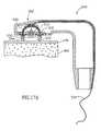
- FIG. 19illustrates a bone-boring head mounted at an end of an endoscope, catheter or trocar, in accordance with a preferred embodiment of the invention
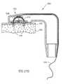
- FIG. 20illustrates a bone-boring head mounted at a side of an endoscope, catheter or trocar, in accordance with a preferred embodiment of the invention.
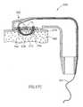
- FIG. 21illustrates a method of treating a fractured bone, in accordance with a preferred embodiment of the invention.
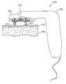
- FIGS. 1A and 1Bare schematic illustrations of a bone-boring device 100 , in un-activated and activated configurations, respectively, in accordance with a preferred embodiment of the invention.
- Device 100generally comprises a base 102 including a bone-boring head 104 , a handle 106 , possibly including a lever 108 and a shaft 110 interconnecting the handle and the base.
- a pair of needles 112 of bone-boring head 104are retracted.
- needles 112rotate and extend, boring a hole in adjacent bone.
- the device shown in FIG. 1A and 1Bis suitable for attaching sutures to an inside face of a pubic bone.
- needles 112extend towards the handle.
- boring-head 104is placed against the pubic bone, upwards pressure being applied to handle 106 to assure good contact between the boring head and the bone, and then lever 108 is depressed to advance needles 112 and bore the hole.
- bone-boring head 104may extend away from handle 106 or at a different orientation thereto and may even be adjustable between several orientations.
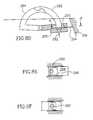
- FIG. 2is a schematic illustration of a hinged dual-needle boring-head 120 , in accordance with a preferred embodiment of the invention.
- head 120comprises a needle 122 and a needle 124 that share a common hinge 126 .
- the needlesrotate around the hinge, they form a channel 128 in the bone.
- the needlesare arranged to enter the bone at a non-perpendicular angle thereto.
- forces applied by the two needles to the bonecooperate for drilling a bore.
- rotation of needle 124 around its hingeapplies a force vector FV 1 , which can be represented by its components FX 1 and FY 1 .
- needle 122applies a force vector FV 2 , represented by components FX 2 and FY 2 .
- An additional force FCis applied by the needles (or by a resting point 134 , FIG. 3A below) as a result of a physician urging boring-head 120 against the bone.
- Force FCis also found in a needle that is directed perpendicular to the bone. FC urges the needle into the bone.
- the bonehas a large resistance to penetration by the needle, a large FC is required to effect that entry, which force is applied from outside the body.
- the force applicatoris not stable, allowing the needle to slip and/or penetrate at an undesirable angle and/or form an undesirable channel.
- forces FX 1 and FX 2are in opposing directions, thus stabilizing head 120 from moving.
- the channelis not perpendicular to the bone surface but also includes a significant X component, already at its start.
- the FX forcescan start boring in the desired direction immediately.
- the FY forcescan start boring, even without an FC force (or with a reduced one) to hold the needles against the bone, since the bone, overlying the needles, holds them in place.
- the needlesare forced through soft tissue, once the soft tissue is pierced, the soft tissue assists in holding the needles against the bone.
- forces FY 1 and FY 2are generated at the boring-head and are typically, but not necessarily, smaller than force FC.
- the application of forces FY 1 and FY 2is at least somewhat decoupled from the FC force, making them easier to control, so that increasing these forces or decreasing them (for example by a sudden give of the bone) do not necessarily affect the application of force FC to the handle.
- the bone boring headis more stable.
- FIGS. 3A and 3Billustrate the action of a leveraged hinged dual needle boring head 130 , in accordance with a preferred embodiment of the invention, in this embodiment, not only are the bone-penetration forces generated near the head, but also any force amplification necessary for generating these forces is also performed near the head, so that there is less variation in the force that is transferred along the device. Thus, a more stable and/or easy to use device is provided.
- force amplification and/or transductionis provided by translating substantially linear motion of a lever 136 and a lever 138 into rotation of needles 122 and 124 .
- lever 136 and needle 122are formed of a single piece of material, possibly increasing reliability and/or reducing cost.
- the linear forceis applied to levers 136 and 138 using anchors 140 and 142 , for example holes.
- a shield 132preferably prevents the needle tips from engaging tissue when the needles are retracted. Alternatively (and as shown), the tips of the needles may peek out beyond the shield, but possibly not beyond the resting point 134 (described below).
- attack angle of the needlesand especially of the tip thereof, which can affect the force vectors at the tip (i) when the needle enters the bone and (ii) when the needle travels through the bone;
- the effect of the attack anglebeing, for example, neutral, urging the needle towards the hinge, urging the needle away from the hinge or urging the needle in a plane perpendicular to the needle;
- penetration depthi.e., a distance between where the needles meet inside the bone and a resting point 134 of the bore-head against the bone surface (shown slightly separated from the surface, for clarity of presentation);
- FIG. 3Cillustrates a replaceable needle-boring head 150 , in accordance with a preferred embodiment of the invention.
- a plurality of matching protrusions and depressions 154 and 152are preferably provided on the boring head and on the base of the device, to align the head and the device.
- a coupler 156 and a coupler 158are provided at the ends of force transmission bars (described in FIGS. 4A and 4B ) which engage anchors 140 and 142 .
- the coupleris a snap coupler which can be separated by the application of sufficient force.
- the boring headincludes means for adjusting one or more of the above parameters.
- the penetration depthcan be adjusted by increasing a distance between resting point 134 and hinge 126 , for example using a screw mechanism. This also affects the distance between the entry holes of the needles.
- the two needlesmay have different cross-sections, different radii of rotation, different leverage, different angles of attack (penetration of the tip) and/or other characteristics in which they are different. In some preferred embodiments of the invention, however, the needles are substantially the same.
- the two needlescan use different hinges, possibly with a controllable distance (in the X and/or Y axes) between the hinges, in a preferred embodiment of the invention, a single hinge is shared by the two needles, as shown.
- FIGS. 4A and 4Bschematically illustrate a bone boring device 200 , in accordance with an alternative preferred embodiment of the invention.
- Device 200comprises a base 202 having a boring-head such as boring head 130 , mounted thereon.
- Base 202is connected to a shank 210 , having a lever 206 coupled thereto.
- a contra-force spring 214couples lever 206 to shank 210 .
- head 130(actually resting point 134 ) is placed against a pubic bone (not shown).
- Lever 206is pulled away from the boring head against the resistance of spring 214 .
- the motion of lever 206only urges resting point 134 against the pubic bone (the force being transmitted by spring 214 ), compressing intermediate tissue.
- lever 206does not extend the needles.
- handle 206engages an engager, such as a protrusion 216 provided on a force-transferring element 212 .
- an engagersuch as a protrusion 216 provided on a force-transferring element 212 .
- further motion of lever 206causes force to be transmitted to element 212 and hence to boring head 130 , causing the needles to extend.
- a peg (or other type of latch) 218further couples lever 206 to force transferring element 212 via an indentation 219 in element 212 .
- Element 212rotates one, possibly two levers 220 and 222 around their respective hinges 224 and 226 , thereby causing a bar 230 and a bar 232 , coupled to the levers, to move along the base and transfer force to the levers of the boring-head (which move as described above with reference to FIGS. 3 A and 3 B).
- the configuration of the two leversreduces the transferred force.
- the leversincrease the transmitted force, while reducing the travel distance.
- peg 218forces the needles to be retracted, before reducing the pressure of head 130 against the pubic bone. Thus, there is less likelihood of the needles damaging the bone after the bone boring is completed.
- peg 218is disengaged (for example by an inclined portion 221 of the peg when it is urged against a protrusion 223 ) and device 200 can be removed from the pubic bone.
- peg 218does not disengage, so that device 200 is substantially a one-use device.
- peg 218is disengaged by a specially provided control, such as a button, to prevent inadvertent reuse of the device before the physician is ready for another bone-boring process.
- a safety latchmay be provided which does not allow lever 206 to travel far enough along shank 210 to extend the needles, unless the latch is released. Thus, inadvertent damage to tissue by the needles is less likely.
- a pin(not shown) may be provided at or about resting point 134 , which pin, if depressed with sufficient force, causes the needles or their levers to engage the bars 230 and 232 . If an insufficient force is presented, the needles are not coupled to the bars and cannot be extended.
- a springis provided at the needles, which spring retracts the needles from the bone if no opposite force is provided by the bars. Thus, if there is insufficient pressure on the pin, the needles are retracted.
- Such a pinmay act in a purely mechanical fashion or may include an electrical circuit to alert the operator and/or actively retract the needles.
- a designated resting point 134is not required. However, in many cases it is desirable that the needles be completely retracted and some element is generally required for compressing intermediate soft tissue and/or for stabilizing the boring head.
- spring 214In devices not meant for the pubic area, or in devices in which boring head 130 can point away from lever 206 , spring 214 , protrusion 216 and peg 218 may need to be replaced and/or augmented by suitably located elements which perform their functions, in a reverse direction. Additionally, various designs of handles, for example axial or perpendicular to the device body may be provided.
- Element 212is shown as a bar. However, it is noted that most of the force is applied when extending the needles. Thus, element 212 may have its function served by a wire, preferably with a retraction spring for retracting the needles when lever 206 is released.
- bars 230 and 232may be replaced by wires.
- a coaxial wire pairis used, in which the inner wire is attached to one lever and the outer one to the other lever.
- boring head 130can be more easily twisted around base 202 and/or otherwise moved.
- a springis provided to retract the needles once they are extended.
- the resistance of spring 214is related to the total force applied against the pubic bone.
- the tension in spring 214can be adjusted to require a physician to apply a desirable minimum pressure against the pubic bone.
- the linearity of the spring and/or the force constant of the springmay be varied to match a desired profile of applying force to the needles and/or to provide better controllability of the force. In one example, a large force is required to enter the bone, but, once the bone is entered, possibly less additional force is required to continue the boring.
- the physicianbe provided with a tactile indication of the extension of the needles. This may be achieved by putting a protrusion on shank 210 , under spring 214 at a point corresponding to the extension of the needles. Thus, as the lever is pulled a “bump” is felt at that point. Additional such protrusions may be provided at other points on the shank, for example at a point where the needles are fully extended and no further force is required. Alternatively or additionally, to these bumps transmitting feed-back to the physician, the bumps may be used to control the device, for example as a safety mechanism that allows the needles to extend or as a control which “fires” the thread (as described below).
- a large protrusion 217is provided underlying spring 214 and frictionally engaging lever 206 , so that compressing the soft tissue will be more difficult than advancing the needles. Possibly, the protrusion applies more friction when the lever is pulled than when the lever is released, for example by suitable machining of its surface.
- the various parameters, such as spring constant, amount of motion and needle leverageare adapted so that a 100 N force is required to compress the soft tissue prior to the extension of the needles.
- An additional force of 40 Nis preferably required for extension of the needle through a typical pubic bone.
- the total motion of the leveris 10 mm for compressing the tissue and 4 mm for extending the needles.
- a non-movable handlemay also be provided, for example for co-gripping with lever 206 .
- air-pressureinstead of manual forces used to power the needle head, air-pressure, electric or other types of power sources may be used.
- a channelis created in the bone and a thread can be passed through the channel.
- the threadis passed through a channel forming in and/or along the body of the needles.
- the threadmay be inserted with the needles, while they bore, or after the boring is completed.
- the deviceis used only to bore a hole in the channel and not to pass a thread, which may be passed manually, for example, if so desired, preferably after the needles are removed.
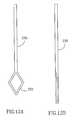
- FIG. 5Aillustrates an end to end needle configuration, in accordance with a preferred embodiment of the invention.
- a needle 240 and a needle 242meet end to end. It should be appreciated that, in accordance with some preferred embodiments of the invention, better control over the final location of the needles is possible if the needles are rigidly attached to a single hinge than if they do not use hinges or are attached to separate hinges.
- Needles 240 and 242preferably comprise an inner bore, such that when they meet end to end, a path 241 is formed therethrough.
- FIG. 5Billustrates various suitable cross-sections for needles 240 and 242 .
- Cross-sections 248 and 246are triangular cross-sections, having a circular inner bore.
- Cross-section 250is circular, with a circular inner bore.
- Cross-section 252is an example of an open-bore needle, having a “U” shaped cross-section, with the bore on the inside of the “U”.
- a groove on the side of a substantially solid needleis used instead of a deeply grooved cross-section such as a “U”.
- the cross-section of the needlemay vary along the needle, for example, there being a groove for the thread along most of the needle and an inner bore only at the needle tip.
- the tip of one needlemay be narrow enough to enter the tip of the other needle, forming an inside-outside matching.
- one needlehas a removable tip, to which the thread is attached, which tip is captured by the other needle.
- the attachment methodcan be, for example, using a knot, in a crevice in the tip or using other methods of attaching a thread to a metal object, as known, for example, in the art of bone anchors.
- the base of the needlesis cleaned out, for example using suction, forward flow of a saline solution or an advancing mandrel, to remove bone debris that accumulates in the bore.
- An opening at the side of the needlemay be provided for the exit of such material, or such a hole may be defined when the two needles meet.
- a somewhat rigid thread pusheris provided, which can push the bone debris ahead of itself or form a channel in the debris.
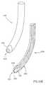
- FIGS. 6A and 6Bare a side and a top view of a side-by-side needle configuration, in accordance with a preferred embodiment of the invention.
- a needle 254 and a needle 252overlap at an area 256 thereof.
- a bore- 258is formed from the bores of the individual needles.
- the bore of the individual needlesdo not reach the tip of the needle but exit the needle at its side, near the tip, so the tip can be solid. When the two needles overlap properly, the bore exits meet and bore 258 is formed.
- the retracting solid tipsmay shear the thread between them.
- the tiphas a smaller cross-section then the rest of the needle.
- Another possible solutionis providing a metallic thread pusher or thread, which is less likely to be sheared.
- the inside faces of the tipsare inclined, so the shear forces on the thread are gradual and smaller.
- the two needleshave different radiuses or rotation and/or the hinge is not at their center of curvature, so that when they retract, they move apart. Such moving apart can also be achieved by using needle tips that are not symmetrical, so that when they are advanced and/or retracted through bone, a force is generated perpendicular to the line of motion of the needle.
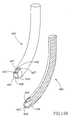
- FIG. 7Aillustrates a top-bottom needle configuration, in accordance with a preferred embodiment of the invention.
- the needlesare one on top of the other (or inside the other, with respect to the view from the hinge), effectively being side-to-side in the plane of the needles.
- a needle 264is inside a radius of needle 262 , and the two needles overlap at an overlap area 266 .
- FIG. 7Billustrates various possible bores for the overlap area, for example two opposing “U”-shaped bores ( 268 ) or two opposing “V” shaped bores ( 270 ). This bore may be open for the entire length of the needle or only at the overlap area.
- the radius of needle 264is smaller than the radius of needle 262 , when measured from the hinge.
- the needlesare not perfect arcs and/or the radius of the needles does not match the radius of rotation. Properly configured, such construction will cause the needles to engage each other when they meet at overlap 266 , instead of sliding over each other.
- a similar resultcan be achieved with side-by-side needles, where the needles do not travel in exactly parallel planes, so once they meet, further movement is difficult or impossible.
- FIGS. 8A-8Cillustrate a detachable needle configuration 280 , and its use in boring and threading a bone, in accordance with a preferred embodiment of the invention.
- Configuration 280includes a non-detachable needle 284 , and a detachable needle 282 , mounted on a base 286 .
- Needle 284includes a tip 288 and needle 282 includes a tip 290 ; these tips are designed to engage, once they meet.
- tip 288enters into a bore in tip 290 and one or both tips are elastically or plastically deformed so that the tips engage.
- needle 282stays latched to needle 284 and is pulled out along the path of needle 284 , rather than back along its path.
- a thread 292is attached to needle 282 , such that the thread is pulled along by needle 282 when it advances. Many methods are known in the art for attaching a thread to a needle.
- FIG. 8Cshows the result of the process, which is a path threaded by a thread 292 .
- needle 282needs to be detachable. Rather, it is enough that any part to which the thread is attached is detachable. Thus, in some embodiment, only the tip of needle 282 is detached. Preferably, a groove or a bore is defined in needle 282 , so that the boring in the bone does not damage the thread. Also, although needle 284 is portrayed as non-detachable, in some embodiments, it may be desirable to allow needle 284 to be detachable, for example outside the body, for replacement thereof.
- needle 282includes a safety latch that releases the needle only if the needle is actually engaged by needle 284 , so that needle 282 is not inadvertently left in the bone.
- FIGS. 8D-8Fillustrate a safety latch which releases the detachable needle of FIGS. 8A-8C only if the two needles 282 and 284 meet, in accordance with a preferred embodiment of the invention.
- a pin 294is arranged in a slot 295 in base 286 .
- the base of pin 294is possibly urged against an incline 296 , for example using a spring (not shown).
- a flexible pinmay be provided which is attached to a fixed location.
- pin 294As needle 282 is advanced, pin 294 , urged by the incline, slides in slot 295 . At a certain point, the motion of pin 294 releases needle 282 .
- FIG. 8Eshown a method in which pin 294 has an aperture 298 formed therein. When the pin is moved, shown in FIG. 8F , the needle is disengaged from the pin and can be extracted by needle 284 that engages it.
- an electrical sensormay be used to sense when the needles meet, for example from the amount of motion of the needles.
- the sensordirectly senses the contact between the needles, for example by measuring a reduced electrical resistance when the needles meet.
- the signal generated by this sensorcan have one or more uses, including indicating to a physician that contact was made (preferably using a light or a sound), freeing the detachable needle or “firing” a thread (described below).
- the needles described aboveare pushed into the bone and they form a channel by forcing through the bone, rather than by removing bone material.
- the needle cross-sectionmay be selected so that the needle removes and/or pulverizes bone when the needle advances.
- the needle's cross-section, especially at the tipmatches the direction of fibers in the bone, so that it can better enter the bone without cutting across fibers.
- one or both needlesare smooth.
- a needlemay be grooved, especially at its tip. Possibly, a spiral is defined on the outside of a needle. It is noted that the finishing and geometry of the outside surface of the needle can affect the direction of advancing of the needle in the bone.
- the needleshave a radius of curvature of about 6 mm, a cross-section diameter of between 1 and 1.5 mm and are formed of surgical tool grade stainless steel or implant grade stainless steel.
- a radius of 4 or 3 mm and a diameter or 0.75 or 0.5 mmare possible, for example a radius of 4 or 3 mm and a diameter or 0.75 or 0.5 mm.
- the needlesare simply pushed into the bone.
- the needlesmay be vibrated (axially, trans-axially and/or rotationally, preferably in a reciprocating manner), for example using a piezoelectric motor coupled to them, to aid their advancement into the bone.
- the needlesare advanced and retracted by the action of lever 106 or 206 , allowing the boring and threading process to be paced by a physician.
- the needlesmay include a self-retracting mechanism, in which, once the needles bore the hole, they are automatically retracted. This may be achieved using a mechanism similar to that of FIGS. 8D-8F , which is used to couple the needles to their levers.
- the automatic retractionoccurs after the thread is threaded through the needles.
- one of the two needlescan be a non-penetrating needle, for example a flat (possibly angled) anvil.
- the anvilincludes a hole to receive the other needle.
- the anvilalso advances when the needle advances.
- the anvilis fixed.
- the anvilincludes small spikes or other gripping elements for engaging the bone so the anvil does not slip and/or to assist in applying a contra-force to stabilize the needle.
- FIGS. 9A and 9Bschematically illustrate a hinged single needle boring head 300 , without an anvil, in accordance with a preferred embodiment of the invention.
- Head 300comprises a needle 302 connected to a hinge 306 via a needle arm 304 .
- needle arm 304also serves as a needle stop to stop the advance of the needle once it completes its path.
- FIG. 9Bshows the single needle when it completes boring through the bone. If needle 302 (or a tip thereof) is detachable from needle arm 304 and is attached to a thread, the tip of needle 302 can be captured by a capture device (not shown), for example by friction, once it exits the bone.
- a capture devicenot shown
- the mechanism of FIG. 9is used for a pair of needles, to avoid the need for the needle tips to interlock.
- the holeis bored by two needles that meet in the bone. Once the needles meet, their rotation mechanism locks, rather than the needles. Then the rotation of one of the needles is continued over more than 90° (as shown in FIG. 9B for a single needle, for example). Since the mechanism is locked, the other needle is retracted along its bore. Once the advancing needle's tip is outside the bone, it can be engaged by the bone boring device and detached at its base (like needle 282 in FIG.
- a thread attached to the advancing needleis threaded through the bore in the bone.
- only one of the needlesrotates more than 90°, however, based on the geometry, it might be required for both needles to travel at least an angle of 110°, for example.
- the needle that travels a longer pathmay be grasped in its middle, at least during the bone boring step, to prevent its distortion. However, this is not essential.
- a feature of some preferred embodiments of the inventionis an invariance to the angle of incidence between the boring head and the bone.
- This invariancehas several aspects, one or more of which are provided by some preferred embodiments of the invention:
- FIG. 10Aillustrates an angle independence of boring head 130 , in accordance with a preferred embodiment of the invention. Due to there being only a small distance between resting point 134 and hinge 126 , the penetration depth is unaffected by small, and even some large angles between the resting point and the bone, since rotation around the resting point does not substantially affect the distance between the resting point and the meeting point of the needles. In a preferred embodiment of the invention, the small distance is less than 60%, 40%, 20% or 10% of a radius of curvature of a path along which said needles travel. Due to the simultaneous gripping of the bone by two opposing needles, slippage is prevented.
- resting point 134allows the needles to penetrate the bone at many different attack angles, even if the needles are not in contact with the bone at a beginning of extension, since the resting point is.
- the resting pointsmay be roughened or include barbs, to assist in its engaging the bone and/or intervening soft tissue.
- the gain for each needlemay be different, so they rotate at different speeds and different entry angles are provided.
- FIG. 10Billustrates a self-aligning boring head 320 , in accordance with a preferred embodiment of the invention.
- head 320is gimbaled on one or more hinges 326 , so that head 320 is always facing to the bone, such that both the needles can enter the bone at substantially the same angle and time.
- a pair of stabilizers 322 and 324contact the bone and straighten head 320 .
- an integral hingemay be used, for example one formed of silicon rubber.
- three or more stabilizersare provided, to provide stability also in the plane perpendicular to the needle path.
- the tips of the stabilizersare soft, to prevent inadvertent damage to soft tissue.
- head 320is self-aligning even without such stabilizers, by the unequal forces against the needles causing the head to gimbal.
- the mechanism for rotating the needlesmay only rotate one needle relative to the other. The absolute angular position of the needles is determined by the relative resistance each needle feels.
- head 320can include one or more sensors for determining that the head is in a correct configuration.
- a force sensoris provided at each of the stabilizers, to determine a contact force, which should be approximately the same for all the stabilizers.
- force sensorsare connected to the needles, both of which should measure about equal forces.
- the result of the sensor measurementis portrayed to a user, for example as a go/no-go signal.
- the signal from the sensoris used to free a pin, which freeing will allow the extension of the needles.
- a mechanical constructionmay be provided, which allows motion of the needles and/or force to be transferred to the needles only if the pressure on the stabilizers and/or their alignment is about the same.
- angleshas been mainly with respect to an angle in the plane of the needles, similar considerations, measurements and apparatus can be utilized for controlling the angle between the needle plane and the surface of the bone.
- the above descriptionhas been mainly directed to needles that share a plane or that travel in parallel planes.
- the needlesmay travel in two oblique planes.
- An extreme exampleis cork-screw needles which twist around their own axis (and may be coaxial).
- Another exampleis a boring-head comprising three needles, which meet at a point inside the bone. It is noted that the hinge does not need to be at the center of rotation of the needles (if they have one).
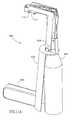
- FIGS. 11A and 11Billustrate a self-aligning boring device 400 in accordance with a preferred embodiment of the invention.
- Device 400comprises generally of a holder 402 and a boring mechanism 404 and a boring head 412 which is held against a bone by force applied by a user to a handle 406 .
- mechanism 404includes a power source such as a motor and head 412 includes drill bits powered by the motor.
- a hinge 410is preferably provided between holder 402 and mechanism 404 , preferably near boring head 412 , to allow boring head 412 to align itself with the surface of the bone to be bored into, substantially independently of the force vector applied to handle 406 .
- a second hinge 408may be provided to maintain the relative positions of holder 402 and mechanism 404 and/or as a safety feature to prevent warping of head 412 by undue forces.
- reference 408may represent a safety catch which prevents the extension of the needles until released.
- FIG. 11Bis a different view of device 400 and showing a relative rotation of holder 402 and mechanism 404 around hinge 410 .
- the hingeis substantially equidistant from the tips of the drill bit, so that a substantially equal force is applied to them.
- the hingemay be positioned not equidistant, for example, if an unequal force on the two drill bits is desired. Alternatively or additionally, such an unequal force can be provided using a spring which resist the gimbaling of the head.
- the hingemay be in the head or in the body, for example.
- holder 402is used as an outer skeleton for an existing mechanism 404 , which mechanism can also be used without holder 402 .
- a holder-type devicemay be used for other uses than boring holes in bones, for example for stapling and/or tacking in the vagina or the throat.
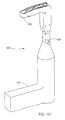
- FIG. 11Cillustrates an alternative self-aligning boring device 420 , in accordance with a preferred embodiment of the invention.
- a boring head 422rotates around a hinge 428 which is between a handle 426 and boring head 422 .
- the angular freedom of hinge 428is small, for example 5°, 10° or 20°.
- the path bored in the bonecan be threaded in different ways.
- a threadis pulled through the path by one of the needles.
- the threadis pushed through the path.
- a separate threaded needleis brought through the path.
- One the pathis threaded, the ends of the suture are tied together, preferably manually.
- a clipis attached to the two ends of the thread and performs the functions of a knot.
- the deviceperforms the threading, when the device is retracted from the one, the thread remains in the bone.
- the suturemay be tied immediately. In some cases, some or all the required bone bores are formed first and the threaded and/or tying of sutures is performed later.
- a general process of bone suturingin accordance with some preferred embodiments of the invention thus comprises:
- selected ones of these stepsmay be performed sequentially or simultaneously. Even in cases when sequential steps are performed, the transition between the steps may be automatic, for example advancing a thread when the needles are fully extended, or manual, for example requiring a user action (manually advancing a thread) or allowance (releasing a safety latch).
- a threadmay be pushed through the bores of the needles, after they meet.
- pushing a threadwill require the thread itself to be stiff or to be attached to a stiff thread pusher, which is pushed and carries the ductile thread along with it.
- the stiffness of the thread/thread pusherdepends, inter alia, on the radius of the bore, the amount of bone material in the bore and the type of mechanism used to advance the thread.
- FIGS. 12A and 12Billustrate a thread pusher 330 , in accordance with a preferred embodiment of the invention in an open configuration and in a closed configuration.
- pusher 330is formed of an elastic or super elastic material and has an eye 332 formed at one end thereof.
- a threadis threaded through the eye and then the thread pusher is inserted into a channel (or the needle bore). The dimensions of the channel compress the eye, so that it grips the thread.
- a double threadmay be used, so that both ends of the thread are far away from the eye.
- FIGS. 13A and 13Billustrate a method of passing a thread through the bores of the needles of FIGS. 5A and 5B , in accordance with a preferred embodiment of the invention.
- a channel 334contains thread pusher 330 .
- a lever 338is coupled to thread pusher 330 , such that moving the lever advances the thread pusher.
- reference number 336may indicate an extension of thread pusher 330 or a thread attached to thread pusher 330 .
- engager 340possibly a friction element, engages thread pusher 330 and/or the thread, so that it does not retract when the needles are retracted and/or when the device is removed from the bone.
- engager 340may also release a catch on a spring that retracts the needles.
- thread pusher 330is urged forward by a spring 342 (shown schematically). However, advance of pusher 330 is prevented by lever 338 .
- a pinsuch as shown in FIGS. 8D-8F , prevents the thread pusher from entering the needle bore, even if it is urged forward by a spring.
- the tip of thread pusher 330is preloaded into the tip of needle 242 , so that it travels with the needle.
- channel 334is arranged so that it has a clear view of the bore only when the needle is fully extended.
- bar 232 and/or bar 230when they completely extend the needles, continue their travel (preferably sliding along anchors 140 and 142 ) and are used to retract the thread pusher and/or to advance it.
- FIGS. 14A-14Dillustrate various stages in usage of a thread-exchanging needle assembly 350 , in accordance with a preferred embodiment of the invention.
- Assembly 350preferably comprises a needle 352 , a needle 354 , a tip 356 mounted on needle 350 and attached to a thread 358 .
- the tips of needles 352 and 354are formed to engage tip 356 in the following manner.
- Tip 356is preferably frictionally engaged by needle 352 so that it does not fall off (FIG. 14 A). Whenever two needles are brought together, the point of tip 356 is engaged by an inner bore (or other spatial configuration) of needle 354 (FIG. 14 B). When the needles are retracted (FIG.
- needle 354is replaced by an anvil (which does not enter the bone) or by a tip-engager that is distanced from the bone, but is within the needle track.
- FIGS. 14E-14Hillustrate needle- (or needle-tip) receiving tips in accordance with various preferred embodiments of the invention.
- FIG. 14Eillustrates a needle 430 , having an aperture 432 formed at its tip.
- An inner volume 438is hollowed out in the needle.
- an outer lip 436 of the aperturehas a smaller diameter than that of volume 438 .
- Lip 436is preferably smooth, however, this is not essential and lip 436 may be, for example, jagged.
- an incline 434is defined adjacent aperture 432 , to bridge the outer diameters of needle 430 and lip 436 .
- volume 438is longer than shown and exits the side of needle 438 at a location marked 439 .
- any bone material that enters volume 438can be pressed out by the received tip of the opposite needle.
- FIG. 14Fillustrates an aperture 442 for a needle 440 , similar to the design shown in FIG. 14E , except that one or more slots 447 are formed between a volume 448 defined in the needle and an incline 444 on the outside of the needle. Slot 447 can server to exhaust debris from volume 448 and/or for adding elasticity to aperture 442 , for assisting in engaging the tip of the opposite needle.
- FIG. 14Gillustrates a needle tip design similar to that of FIG. 14F , except that two slots 477 are defined between a volume 458 in a needle 450 and an incline portion 454 of the needle.
- the two slotsare nearby, defining a flexible tab 455 between them.
- Tab 455can, for example, provided an elasticity or plasticity in an aperture 452 , to engage the other needle tip.
- FIG. 14Hillustrates a variant of the design of FIG. 14G , in which a pair of slots 467 do not extent to a lip 462 of an aperture 466 defined in a needle 460 . Rather, a small slot 463 bridges between the ends of slots 467 , so that a tab 465 is formed. Lip 462 is thus whole and tab 465 is less likely to be distorted by the travel in the bone than is the design of FIG. 14 G.
- FIGS. 15A-15Dillustrates a hollow needle boring mechanism, in accordance with a preferred embodiment of the invention, in which a bore in one of the needles is filled by a retracting mandrel.
- FIG. 15Aillustrates a needle-boring head 470 , having two opposing hollow needles, a needle 472 which carries a tip 482 and a tip-receiving needle 474 .
- needle 472is not hollow, for example as described above.
- the two needlespreferably rotate around a hinge 476 .
- Tip 482is preferably attached to a thread 484 , which can be carried past a bore 486 of needle 472 , to a conduit 488 , preferably an elastic conduit, for example an axially flexible conduit.
- a mandrel 490is preferably provided in a bore 475 of needle 474 .
- Mandrel 490is preferably maintained in an axial position relative to needle 474 for example by a stop-clip 492 .
- Stop clip 492preferably includes a base 493 against which mandrel 490 is placed, an arm 494 which engages a protrusion 496 of needle 474 , so that stop clip 492 holds mandrel 490 in place.
- Stop clip 492preferably also includes an extension 491 , adapted to match a protrusion 498 in head 470 , for releasing stop-clip 492 .
- FIG. 15Ashows mandrel 490 and tip 482 forced into or against a cortex layer 478 of a bone and overlaying a medulla 480 of the bone.
- the tissuemay be removed or is not shown for clarity of presentation.
- FIG. 15Bthe needles are rotated around hinge 476 , so they create a bore 499 through cortex 478 and medulla 480 .
- extension 491is stopped by protrusion 498 , causing stop-clip 492 to disengage from needle 474 and allowing mandrel 490 to retract.
- an apertureappears in the tip of needle 474 , into which tip 482 can enter and by which it can be engaged.
- the tip of needle 474is slotted, for example as described with reference to FIGS. 14F-14G .
- bore 475is filled with debris from medulla 480 , as mandrel 490 retracts, preventing the formed aperture from being blocked.
- boring head 470is separated from the bone, leaving thread 484 threaded through bore 499 .
- a thread 484is actually a metallic extension of tip 482 , for example made of Nitinol, to which a thread may be connected.
- the threadis far away from tip 482 and is not near the bone during the boring procedure.
- a hollow needle with a mandrelmay also be used for a single needle device, such as shown in FIGS. 9 , for example to assist in engaging the needle when it finishes its travel.
- FIGS. 16A and 16Billustrate a combination drilling and needle boring head, in accordance with a preferred embodiment of the invention.
- a combined drilling and boring device 500preferably comprises a combination drilling and boring head 502 attached to a handle 501 .
- FIG. 16Ashows device 500 with the needles retracted and FIG. 16B shows the device with the needles extended.
- two drill bits 504are provided, each with one or more openings 506 in its side for passage of one of a needle 508 and a needle 510 .
- the needlesmay share a single hinge, or as shown in the Figure, a hinge 512 may be provided for each needle, coupling the respective needles to a casing 514 of head 502 .
- Various lever typesmay be used for leveraging the extension of the needles.
- a power train 516is shown for advancing the needles.
- a power train 518is shown for rotating the drill bits.
- FIG. 16Bshows head 502 with the boring needles extended, and also affords a better view of the drive mechanism for rotating the drill bits.
- the rotation of drive train 518is preferably transferred to a flat gear 520 , which rotates a gear 522 that has a drill bit at its center.
- a second gear 524transfers power from gear 522 to a gear 526 that also has a drill bit at its center.
- only one drillis used, possibly with a single needle extending through that drill bit.
- a peg 528is shown which allows some rotational freedom of the drill bits, so that the needles can be more easily aligned with openings 506 .
- the position of peg 528is detected using a sensor (not shown), which sensor electrically or mechanically stops the rotation of the drill bits, so they will be correctly aligned.
- a sensornot shown
- exemplary suitable sensorsare optical and magnetic sensors.
- a rotational encoderis used to detect the drill bit position. The rotation may be stopped at any point between the motor and the drill bit, depending on the implementation. Alternatively, the motor may be controlled to generate complete rotations, so that the end-position of the drill-bit can be as desired.
- the two drill bitsrotate in a same direction and at a same speed. Alternatively, they may rotate in opposite directions and/or at different speeds. Alternatively, they may have reciprocating motion, rather than pure rotational motion. In some cases, axial or transaxial vibration may also be provided.
- a spikeis provided between the drill bits, for maintaining the bits in place before they penetrate the bone. This spike is preferably retracted as the bits advance.
- FIGS. 17A-17Eillustrate a method of using device 500 . Some of the elements of head 502 are not shown, for clarity of presentation.
- drill bits 504are against a cortex 478 of a bone.
- the needles used in this exemplary embodimentare a bored needle 508 having a detachable tip 530 threaded with a thread 534 and a solid needle 520 with a through aperture 532 embedded in its tip, for receiving detachable tip 530 .
- Other needle typesfor example as described above, may be used instead.
- FIG. 17Bpressure is applied to a handle (not shown) forcing drill bits 504 against cortex 478 , forming a pair of cortex-bores 540 , after they have rotated a sufficient amount.
- the drill bitsare prevented from rotation unless a minimum pressure is applied to them, for example using a mechanical clutch.
- the number of rotations of the drill-bitsis predetermined and once the number is reached the drilling stops.
- drill bits 504are prevented from advancing by the base of head 502 , which contacts the bone or by a suitable protrusion from head 502 (not shown).
- the drilling depthmay be set, for example by moving the protrusion axially relative to the drill bits.
- FIG. 17Cthe needles are advanced so that a bore 542 is formed in medulla 480 and detachable tip 530 is engaged by aperture 532 .
- head 502is retracted, leaving thread 534 (or an extension of tip 530 ) threading the bone.
- FIG. 18illustrates a variant 550 of device 500 , which can adapt to the local bone geometry.
- a boring head 554is mounted on a body 552 , by a hinge 556 . When head 554 is pressed against the bone, the head aligns so that both drill bits 504 contact the bone.
- the threadhas been shown traveling from a left needle to a right needle. It should be appreciated that this convention, as well as other conventions related to mirroring and relative placement of device elements have been adopted for simplicity of description and should not be construed to limit the preferred embodiments to those shown, for example, a thread may travel from the needle on the side of the shank to the needle on the outside of the device (unlike shown in FIG. 13 A).
- the device or parts thereofare made for one time or limited time used.
- sterilization of the devicecan better be achieved.
- issues of wear and maintainabilityare solved, allowing a cheaper device to be manufactured.
- the deviceis a one-patient device and the needles are one-time use.
- the needlesare one-patient use and the sutures and/or thread pusher (if provided) are one-time use.
- the deviceis a multi-use device and the boring head is disposable.
- the thread and its channelmay comprise a disposable cartridge.
- a cartridgemay comprises a plurality of pre-threaded thread pushers, which are advanced one at a time, out of a cartridge (schematically shown as 343 in FIG. 13B ) into the needle bore. As one needle pusher is advanced, the next one becomes available for advancing and comes into contact with spring 342 .
- the disposable needle pusheris provided as an extension of needle pusher 330 .
- the size of cartridge 343can be larger, of course, for example if a long disposable thread pusher is used.
- the retraction of the needlespreferably cocks spring 342 .
- the deviceis tested, preferably on a piece of test material (possibly an in vitro bone), after it is manufactured or prior to its being used by the physician, to insure that the device is operating properly.
- a piece of test materialpossibly an in vitro bone
- the channelis used for attaching soft tissue to a bone, using a thread that grips the bone and is engaged by the channel.
- attaching soft tissueinclude correction a dislocating shoulder (e.g., Bankard procedure), hyoid suspension, and cosmetic applications, such as tightening flabby flesh, by suturing it to a bone.
- FIG. 19illustrates a bone-boring head 360 mounted at an end of an endoscope, catheter or trocar 362 , in accordance with a preferred embodiment of the invention.
- FIG. 20illustrates bone-boring head 360 mounted at a side of endoscope, catheter or trocar 362 , in accordance with a preferred embodiment of the invention. It is expected that only a small pressure is needed to maintain head 360 against a bone prior to the needles engaging the bone. In a trocar, which is substantially rigid, the pressure may be achieved by pushing against the trocar. In an endoscope, which is usually somewhat rigid, the pressure may be applied through the endoscope.
- the pressuremay be applied by advancing the endoscope and using the surrounding body tissues to apply a contra force.
- leversmay not be suitable, due to space constraints, however, other ways of rotating the needle(s) around the hinge may be used, for example, using a screw mechanism or a motor.
- a clamp or a suction nozzlemay be provided to hold head 360 against the hone. The clamp may engage bone or it may engage nearby soft tissue.
- a minimal diameter holeis formed in the body, preferably in an inconspicuous location and a boring head 360 is brought to a location where soft tissue is to be attached to bone.
- the sutureis applied, as described herein and the thread is tied through the hole. Thereafter, the hole is sealed.
- This type of proceduremay be especially useful for surgery of the face when implantation of staples or screws or long incisions may not be viable options.
- Another class of usesis attaching implants, either using a suture, as described above or by inserting a projection of the implant into a channel formed in the bone.
- small bonessuch as wrist bones may be immobilized or prevented from moving apart by threading them together.
- a channelis formed in each bone and then the bones are sutured to each other (or to soft tissue, such as ligaments).
- the fragmentsmay be stitched together.
- the needlesit is advantageous for the needles to oppose each other (180 degrees), possibly traveling in straight lines towards each other.
- a large radius of rotation around the hingeapproximates such straight lines.
- FIG. 21illustrates a plate 374 which is sutured to a fractured bone 370 , using a plurality of sutures 372 .
- holesare pre-formed in the structural element for receiving the needles.
- holes in the structural elementmay be bored in a single step with boring the holes in the bone.
- a biodegradable structural elementis used, so that there is no need to remove it after the bone heals.
- the needlesmay be biodegradable.
- Another relevant procedureis sternal suturing in which a cut-open rig cage is sutured shut.
- plate 374may be an intramedullar nail (possibly not filling the entire cross-section but functioning like plate 374 ) which is inside the bone.
- the above described force transduction mechanismmay be used, noting, that unlike needles, the staples remain in the body. Possibly, the staples are inserted side by side with a pair of needles, each of which needles includes a groove for receiving an arm of the staple and which needle does the actual boring.
- the stapleitself can contain less material and/or otherwise be mechanically weaker.
- the above devicemay be used for tacking, which is a method where a suture or other object is attached to a bone by its being pressed between a tack and the bone.
- tackingis a method where a suture or other object is attached to a bone by its being pressed between a tack and the bone.
- the above devicecan be used for implanting a bone—anchor, noting that since the hole is bored by a needle, the bone anchor can be made with less material, weaker material and/or from bio-absorbable material.
Landscapes
- Health & Medical Sciences (AREA)
- Surgery (AREA)
- Life Sciences & Earth Sciences (AREA)
- Biomedical Technology (AREA)
- Medical Informatics (AREA)
- Veterinary Medicine (AREA)
- Public Health (AREA)
- Engineering & Computer Science (AREA)
- General Health & Medical Sciences (AREA)
- Heart & Thoracic Surgery (AREA)
- Nuclear Medicine, Radiotherapy & Molecular Imaging (AREA)
- Molecular Biology (AREA)
- Animal Behavior & Ethology (AREA)
- Dentistry (AREA)
- Oral & Maxillofacial Surgery (AREA)
- Orthopedic Medicine & Surgery (AREA)
- Surgical Instruments (AREA)
Abstract
Description
Claims (4)
Priority Applications (1)
| Application Number | Priority Date | Filing Date | Title |
|---|---|---|---|
| US10/005,760US6843796B2 (en) | 1999-06-04 | 2001-11-12 | Bone suturing device |
Applications Claiming Priority (4)
| Application Number | Priority Date | Filing Date | Title |
|---|---|---|---|
| IL13030799AIL130307A0 (en) | 1999-06-04 | 1999-06-04 | Bone suturing device |
| IL130307 | 1999-06-04 | ||
| US09/476,682US6328744B1 (en) | 1999-06-04 | 1999-12-30 | Bone suturing device |
| US10/005,760US6843796B2 (en) | 1999-06-04 | 2001-11-12 | Bone suturing device |
Related Parent Applications (1)
| Application Number | Title | Priority Date | Filing Date |
|---|---|---|---|
| US09/476,682DivisionUS6328744B1 (en) | 1999-06-04 | 1999-12-30 | Bone suturing device |
Publications (2)
| Publication Number | Publication Date |
|---|---|
| US20020040227A1 US20020040227A1 (en) | 2002-04-04 |
| US6843796B2true US6843796B2 (en) | 2005-01-18 |
Family
ID=11072879
Family Applications (2)
| Application Number | Title | Priority Date | Filing Date |
|---|---|---|---|
| US09/476,682Expired - Fee RelatedUS6328744B1 (en) | 1999-06-04 | 1999-12-30 | Bone suturing device |
| US10/005,760Expired - LifetimeUS6843796B2 (en) | 1999-06-04 | 2001-11-12 | Bone suturing device |
Family Applications Before (1)
| Application Number | Title | Priority Date | Filing Date |
|---|---|---|---|
| US09/476,682Expired - Fee RelatedUS6328744B1 (en) | 1999-06-04 | 1999-12-30 | Bone suturing device |
Country Status (2)
| Country | Link |
|---|---|
| US (2) | US6328744B1 (en) |
| IL (1) | IL130307A0 (en) |
Cited By (30)
| Publication number | Priority date | Publication date | Assignee | Title |
|---|---|---|---|---|
| US20030220658A1 (en)* | 2002-05-22 | 2003-11-27 | Hatch Laird L. | Suture passing surgical instrument |
| US20040267269A1 (en)* | 2001-06-01 | 2004-12-30 | Middleton Lance M. | Tissue cavitation device and method |
| US20050267483A1 (en)* | 2004-05-28 | 2005-12-01 | Middleton Lance M | Instruments and methods for reducing and stabilizing bone fractures |
| US20070005067A1 (en)* | 2005-06-21 | 2007-01-04 | Brian Dross | Arthoscopic method and apparatus for tissue attachment to bone |
| US20070067034A1 (en)* | 2005-08-31 | 2007-03-22 | Chirico Paul E | Implantable devices and methods for treating micro-architecture deterioration of bone tissue |
| US20070118142A1 (en)* | 2005-11-18 | 2007-05-24 | Krueger John A | Device, system and method for delivering a curable material into bone |
| US20070123894A1 (en)* | 2005-10-25 | 2007-05-31 | Claypool Jody L | Orthopaedic pin driver |
| US20070142842A1 (en)* | 2005-11-18 | 2007-06-21 | Krueger John A | Device, system and method for delivering a curable material into bone |
| US20080114364A1 (en)* | 2006-11-15 | 2008-05-15 | Aoi Medical, Inc. | Tissue cavitation device and method |
| US20080147094A1 (en)* | 2006-12-14 | 2008-06-19 | Depuy Mitek, Inc. | Bone Suture |
| EP1970016A1 (en) | 2007-03-13 | 2008-09-17 | Karl Storz GmbH & Co. KG | Device for securing a surgical thread to a bone |
| US20080294166A1 (en)* | 2007-05-21 | 2008-11-27 | Mark Goldin | Extendable cutting member |
| US20090005782A1 (en)* | 2007-03-02 | 2009-01-01 | Chirico Paul E | Fracture Fixation System and Method |
| US20090216260A1 (en)* | 2008-02-20 | 2009-08-27 | Souza Alison M | Interlocking handle |
| US20090276048A1 (en)* | 2007-05-08 | 2009-11-05 | Chirico Paul E | Devices and method for bilateral support of a compression-fractured vertebral body |
| US20100069913A1 (en)* | 2005-08-31 | 2010-03-18 | Chirico Paul E | Threaded bone filling material plunger |
| US20100168748A1 (en)* | 2008-07-16 | 2010-07-01 | Knopp Peter G | Morselizer |
| US20100217335A1 (en)* | 2008-12-31 | 2010-08-26 | Chirico Paul E | Self-expanding bone stabilization devices |
| US20100241142A1 (en)* | 2009-03-23 | 2010-09-23 | Linvatec Corporation | Suture passing apparatus and method |
| US20110196377A1 (en)* | 2009-08-13 | 2011-08-11 | Zimmer, Inc. | Virtual implant placement in the or |
| US8221420B2 (en) | 2009-02-16 | 2012-07-17 | Aoi Medical, Inc. | Trauma nail accumulator |
| US8277506B2 (en) | 2008-06-24 | 2012-10-02 | Carefusion 2200, Inc. | Method and structure for stabilizing a vertebral body |
| USD669168S1 (en) | 2005-11-18 | 2012-10-16 | Carefusion 2200, Inc. | Vertebral augmentation needle |
| US8690884B2 (en) | 2005-11-18 | 2014-04-08 | Carefusion 2200, Inc. | Multistate-curvature device and method for delivering a curable material into bone |
| US9168078B2 (en) | 2009-11-10 | 2015-10-27 | Carefusion 2200, Inc. | Apparatus and method for stylet-guided vertebral augmentation |
| US9549799B2 (en) | 2005-06-21 | 2017-01-24 | Boston Scientific Scimed, Inc. | Surgical kit for securing an implantable sling in a pubic region |
| US9888915B2 (en) | 2011-02-14 | 2018-02-13 | Smith & Nephew, Inc. | Method and device for suture removal |
| US9936943B1 (en) | 2014-08-07 | 2018-04-10 | Nicholas MANCINI | Suture passing surgical device with atraumatic grasper preventing accidental perforations |
| US10682133B2 (en) | 2016-10-31 | 2020-06-16 | Smith & Nephew, Inc. | Suture passer and grasper instrument and method |
| US10765420B2 (en) | 2014-04-24 | 2020-09-08 | Smith & Nephew, Inc. | Suture passer |
Families Citing this family (141)
| Publication number | Priority date | Publication date | Assignee | Title |
|---|---|---|---|---|
| US6635058B2 (en) | 1992-11-13 | 2003-10-21 | Ams Research Corporation | Bone anchor |
| US6406480B1 (en) | 1992-11-13 | 2002-06-18 | American Med Syst | Bone anchor inserter with retractable shield |
| US6599235B2 (en) | 1997-03-18 | 2003-07-29 | American Medical Systems Inc. | Transvaginal bone anchor implantation device |
| US6039686A (en) | 1997-03-18 | 2000-03-21 | Kovac; S. Robert | System and a method for the long term cure of recurrent urinary female incontinence |
| US6382214B1 (en) | 1998-04-24 | 2002-05-07 | American Medical Systems, Inc. | Methods and apparatus for correction of urinary and gynecological pathologies including treatment of male incontinence and female cystocele |
| JP2002534149A (en) | 1999-01-08 | 2002-10-15 | インフルエンス・メディカル・テクノロジーズ・リミテッド | Tack device |
| IL130307A0 (en) | 1999-06-04 | 2000-06-01 | Influence Med Tech Ltd | Bone suturing device |
| FR2811218B1 (en) | 2000-07-05 | 2003-02-28 | Patrice Suslian | IMPLANTABLE DEVICE FOR CORRECTING URINARY INCONTINENCE |
| US6638211B2 (en) | 2000-07-05 | 2003-10-28 | Mentor Corporation | Method for treating urinary incontinence in women and implantable device intended to correct urinary incontinence |
| US6592515B2 (en) | 2000-09-07 | 2003-07-15 | Ams Research Corporation | Implantable article and method |
| US8167785B2 (en) | 2000-10-12 | 2012-05-01 | Coloplast A/S | Urethral support system |
| US20060205995A1 (en) | 2000-10-12 | 2006-09-14 | Gyne Ideas Limited | Apparatus and method for treating female urinary incontinence |
| GB0025068D0 (en) | 2000-10-12 | 2000-11-29 | Browning Healthcare Ltd | Apparatus and method for treating female urinary incontinence |
| US6652450B2 (en) | 2001-01-23 | 2003-11-25 | American Medical Systems, Inc. | Implantable article and method for treating urinary incontinence using means for repositioning the implantable article |
| US20020147382A1 (en) | 2001-01-23 | 2002-10-10 | Neisz Johann J. | Surgical articles and methods |
| US7229453B2 (en) | 2001-01-23 | 2007-06-12 | Ams Research Corporation | Pelvic floor implant system and method of assembly |
| US7070556B2 (en) | 2002-03-07 | 2006-07-04 | Ams Research Corporation | Transobturator surgical articles and methods |
| US6612977B2 (en) | 2001-01-23 | 2003-09-02 | American Medical Systems Inc. | Sling delivery system and method of use |
| US6641525B2 (en) | 2001-01-23 | 2003-11-04 | Ams Research Corporation | Sling assembly with secure and convenient attachment |
| US6602260B2 (en)* | 2001-02-02 | 2003-08-05 | Ams Research Corporation | Powered bone screw device |
| GB0108088D0 (en) | 2001-03-30 | 2001-05-23 | Browning Healthcare Ltd | Surgical implant |
| US7407480B2 (en) | 2001-07-27 | 2008-08-05 | Ams Research Corporation | Method and apparatus for correction of urinary and gynecological pathologies, including treatment of incontinence cystocele |
| US6648921B2 (en) | 2001-10-03 | 2003-11-18 | Ams Research Corporation | Implantable article |
| US7357773B2 (en) | 2002-03-07 | 2008-04-15 | Ams Research Corporation | Handle and surgical article |
| US6911003B2 (en) | 2002-03-07 | 2005-06-28 | Ams Research Corporation | Transobturator surgical articles and methods |
| US11337728B2 (en) | 2002-05-31 | 2022-05-24 | Teleflex Life Sciences Limited | Powered drivers, intraosseous devices and methods to access bone marrow |
| US11298202B2 (en) | 2002-05-31 | 2022-04-12 | Teleflex Life Sciences Limited | Biopsy devices and related methods |
| US9451968B2 (en) | 2002-05-31 | 2016-09-27 | Vidacare LLC | Powered drivers, intraosseous devices and methods to access bone marrow |
| US20070049945A1 (en) | 2002-05-31 | 2007-03-01 | Miller Larry J | Apparatus and methods to install, support and/or monitor performance of intraosseous devices |
| US8142365B2 (en) | 2002-05-31 | 2012-03-27 | Vidacare Corporation | Apparatus and method for accessing the bone marrow of the sternum |
| US9072543B2 (en) | 2002-05-31 | 2015-07-07 | Vidacare LLC | Vascular access kits and methods |
| US8668698B2 (en) | 2002-05-31 | 2014-03-11 | Vidacare Corporation | Assembly for coupling powered driver with intraosseous device |
| US7951089B2 (en) | 2002-05-31 | 2011-05-31 | Vidacare Corporation | Apparatus and methods to harvest bone and bone marrow |
| EP2039298B1 (en) | 2002-05-31 | 2017-10-25 | Vidacare LLC | Apparatus to access bone marrow |
| US10973532B2 (en) | 2002-05-31 | 2021-04-13 | Teleflex Life Sciences Limited | Powered drivers, intraosseous devices and methods to access bone marrow |
| US8641715B2 (en) | 2002-05-31 | 2014-02-04 | Vidacare Corporation | Manual intraosseous device |
| US9314228B2 (en) | 2002-05-31 | 2016-04-19 | Vidacare LLC | Apparatus and method for accessing the bone marrow |
| US7811260B2 (en) | 2002-05-31 | 2010-10-12 | Vidacare Corporation | Apparatus and method to inject fluids into bone marrow and other target sites |
| US7850620B2 (en) | 2002-05-31 | 2010-12-14 | Vidacare Corporation | Biopsy devices and related methods |
| US8690791B2 (en) | 2002-05-31 | 2014-04-08 | Vidacare Corporation | Apparatus and method to access the bone marrow |
| US10973545B2 (en) | 2002-05-31 | 2021-04-13 | Teleflex Life Sciences Limited | Powered drivers, intraosseous devices and methods to access bone marrow |
| CA2492630C (en) | 2002-08-02 | 2009-01-13 | C.R. Bard, Inc. | Self anchoring sling and introducer system |
| USD543626S1 (en) | 2002-11-27 | 2007-05-29 | Ams Research Corporation | Handle for a surgical instrument |
| GB0307082D0 (en) | 2003-03-27 | 2003-04-30 | Gyne Ideas Ltd | Drug delivery device and method |
| US7494495B2 (en) | 2003-03-28 | 2009-02-24 | Coloplast A/S | Method and implant for curing cystocele |
| EP1610714A2 (en) | 2003-03-28 | 2006-01-04 | Analytic Biosurgical Solutions - ABISS | Implant for treatment of a rectocele and device for placement of said implant |
| US9504477B2 (en) | 2003-05-30 | 2016-11-29 | Vidacare LLC | Powered driver |
| US7341558B2 (en)* | 2003-09-19 | 2008-03-11 | Medcanica, Llc | Pericardial retractor |
| US7347812B2 (en) | 2003-09-22 | 2008-03-25 | Ams Research Corporation | Prolapse repair |
| US7815642B2 (en) | 2004-01-26 | 2010-10-19 | Vidacare Corporation | Impact-driven intraosseous needle |
| CN101536926B (en) | 2004-01-26 | 2012-07-18 | 维达保健公司 | Manual interosseous device |
| US7846183B2 (en) | 2004-02-06 | 2010-12-07 | Spinal Elements, Inc. | Vertebral facet joint prosthesis and method of fixation |
| US7604636B1 (en)* | 2004-04-20 | 2009-10-20 | Biomet Sports Medicine, Llc | Method and apparatus for arthroscopic tunneling |
| US7351197B2 (en) | 2004-05-07 | 2008-04-01 | Ams Research Corporation | Method and apparatus for cystocele repair |
| US7811222B2 (en) | 2004-04-30 | 2010-10-12 | Ams Research Corporation | Method and apparatus for treating pelvic organ prolapse |
| US7500945B2 (en) | 2004-04-30 | 2009-03-10 | Ams Research Corporation | Method and apparatus for treating pelvic organ prolapse |
| GB0411360D0 (en) | 2004-05-21 | 2004-06-23 | Mpathy Medical Devices Ltd | Implant |
| US9504583B2 (en) | 2004-06-10 | 2016-11-29 | Spinal Elements, Inc. | Implant and method for facet immobilization |
| US7682393B2 (en)* | 2004-10-14 | 2010-03-23 | Warsaw Orthopedic, Inc. | Implant system, method, and instrument for augmentation or reconstruction of intervertebral disc |
| US8998848B2 (en) | 2004-11-12 | 2015-04-07 | Vidacare LLC | Intraosseous device and methods for accessing bone marrow in the sternum and other target areas |
| US7947047B2 (en)* | 2005-06-20 | 2011-05-24 | Ams Research Corporation | Medical screwdrivers and methods |
| US8864650B2 (en) | 2005-06-21 | 2014-10-21 | Ams Research Corporation | Methods and apparatus for securing a urethral sling to a pubic bone |
| US8535217B2 (en) | 2005-07-26 | 2013-09-17 | Ams Research Corporation | Methods and systems for treatment of prolapse |
| WO2007059199A2 (en) | 2005-11-14 | 2007-05-24 | C.R. Bard, Inc. | Sling anchor system |
| CA2908132C (en) | 2006-02-16 | 2018-12-11 | Ams Research Corporation | Surgical articles and methods for treating pelvic conditions |
| WO2007137226A2 (en) | 2006-05-19 | 2007-11-29 | Ams Research Corporation | Method and articles for treatment of stress urinary incontinence |
| CN101500507B (en) | 2006-06-16 | 2013-09-25 | Ams研究公司 | Surgical implants, tools for the treatment of pelvic diseases |
| CA2654294C (en) | 2006-06-22 | 2016-09-20 | Ams Research Corporation | Adjustable tension incontinence sling assemblies |
| US8944069B2 (en) | 2006-09-12 | 2015-02-03 | Vidacare Corporation | Assemblies for coupling intraosseous (IO) devices to powered drivers |
| EP2073728B1 (en) | 2006-09-12 | 2018-11-07 | Teleflex Medical Devices S.à.r.l. | Biopsy device |
| EP3189787B1 (en) | 2006-09-12 | 2019-01-09 | Teleflex Medical Devices S.à.r.l. | Medical procedures trays and related methods |
| EP2068743B1 (en) | 2006-09-12 | 2017-03-15 | Vidacare LLC | Medical procedures trays, kits and related methods |
| WO2008033950A2 (en) | 2006-09-13 | 2008-03-20 | C. R. Bard, Inc. | Urethral support system |
| US8951185B2 (en) | 2007-10-26 | 2015-02-10 | Ams Research Corporation | Surgical articles and methods for treating pelvic conditions |
| BRPI0718156A2 (en) | 2006-10-26 | 2013-11-26 | Ams Res Corp | INSERT TOOL AND METHOD FOR PREPARING A SURGICAL TREATMENT SET. |
| US8974410B2 (en) | 2006-10-30 | 2015-03-10 | Vidacare LLC | Apparatus and methods to communicate fluids and/or support intraosseous devices |
| EP2813190B1 (en)* | 2007-02-22 | 2017-04-26 | Spinal Elements, Inc. | Vertebral facet joint drill |
| US8992533B2 (en) | 2007-02-22 | 2015-03-31 | Spinal Elements, Inc. | Vertebral facet joint drill and method of use |
| EP2194913A1 (en) | 2007-09-21 | 2010-06-16 | AMS Research Corporation | Pelvic floor treatments and related tools and implants |
| US8206280B2 (en) | 2007-11-13 | 2012-06-26 | C. R. Bard, Inc. | Adjustable tissue support member |
| US9486126B2 (en) | 2008-06-17 | 2016-11-08 | Apollo Endosurgery, Inc. | Endoscopic helix tissue grasping device |
| US11812951B2 (en) | 2008-06-17 | 2023-11-14 | Apollo Endosurgery Us, Inc. | Endoscopic needle assembly |
| US9867610B2 (en) | 2008-06-17 | 2018-01-16 | Apollo Endosurgery Us, Inc. | Endoscopic suturing system with retained end cap |
| US12108939B2 (en) | 2008-06-17 | 2024-10-08 | Boston Scientific Scimed, Inc. | Endoscopic tissue grasping systems and methods |
| US8727963B2 (en) | 2008-07-31 | 2014-05-20 | Ams Research Corporation | Methods and implants for treating urinary incontinence |
| KR101739304B1 (en) | 2008-08-25 | 2017-05-24 | 에이엠에스 리서치 코포레이션 | Minimally invasive implant system |
| US9017243B2 (en) | 2008-08-25 | 2015-04-28 | Ams Research Corporation | Minimally invasive implant and method |
| US8944990B2 (en) | 2008-10-27 | 2015-02-03 | Ams Research Corporation | Surgical needle and anchor system with retractable features |
| WO2010093421A2 (en) | 2009-02-10 | 2010-08-19 | Ams Research Corporation | Surgical articles and methods for treating urinary incontinence |
| US9345473B2 (en) | 2009-12-30 | 2016-05-24 | Astora Women's Health, Llc | Implantable sling systems and methods |
| US9364308B2 (en) | 2009-12-30 | 2016-06-14 | Astora Women's Health, Llc | Implant systems with tensioning feedback |
| EP2519185A4 (en) | 2009-12-30 | 2018-01-24 | Boston Scientific Scimed, Inc. | Elongate implant system and method for treating pelvic conditions |
| US9393091B2 (en) | 2009-12-31 | 2016-07-19 | Astora Women's Health, Llc | Suture-less tissue fixation for implantable device |
| WO2011106419A1 (en) | 2010-02-23 | 2011-09-01 | Ams Research Corporation | Surgical articles and methods |
| US9445881B2 (en) | 2010-02-23 | 2016-09-20 | Boston Scientific Scimed, Inc. | Surgical articles and methods |
| JP5881696B2 (en) | 2010-07-11 | 2016-03-09 | ミニンヴェイシヴ リミティッド | Annular bone tunneling device |
| US10028813B2 (en) | 2010-07-22 | 2018-07-24 | Boston Scientific Scimed, Inc. | Coated pelvic implant device and method |
| US9572648B2 (en) | 2010-12-21 | 2017-02-21 | Justin M. Crank | Implantable slings and anchor systems |
| US8740949B2 (en) | 2011-02-24 | 2014-06-03 | Spinal Elements, Inc. | Methods and apparatus for stabilizing bone |
| USD724733S1 (en) | 2011-02-24 | 2015-03-17 | Spinal Elements, Inc. | Interbody bone implant |
| US9271765B2 (en) | 2011-02-24 | 2016-03-01 | Spinal Elements, Inc. | Vertebral facet joint fusion implant and method for fusion |
| US9089393B2 (en) | 2011-03-28 | 2015-07-28 | Ams Research Corporation | Implants, tools, and methods for treatment of pelvic conditions |
| US8808162B2 (en) | 2011-03-28 | 2014-08-19 | Ams Research Corporation | Implants, tools, and methods for treatment of pelvic conditions |
| US9492259B2 (en) | 2011-03-30 | 2016-11-15 | Astora Women's Health, Llc | Expandable implant system |
| CA2834273A1 (en) | 2011-05-05 | 2012-11-08 | Ams Research Corporation | Tools and methods for treatment of pelvic conditions |
| US10058240B2 (en) | 2011-06-29 | 2018-08-28 | Boston Scientific Scimed, Inc. | Systems, implants, tools, and methods for treatments of pelvic conditions |
| US9351723B2 (en) | 2011-06-30 | 2016-05-31 | Astora Women's Health, Llc | Implants, tools, and methods for treatments of pelvic conditions |
| EP2734148B1 (en) | 2011-07-22 | 2019-06-05 | Boston Scientific Scimed, Inc. | Pelvic implant system |
| US9414903B2 (en) | 2011-07-22 | 2016-08-16 | Astora Women's Health, Llc | Pelvic implant system and method |
| US9492191B2 (en) | 2011-08-04 | 2016-11-15 | Astora Women's Health, Llc | Tools and methods for treatment of pelvic conditions |
| US20130035555A1 (en) | 2011-08-05 | 2013-02-07 | Alexander James A | Systems, implants, tools, and methods for treatment of pelvic conditions |
| CN106901810B (en)* | 2011-08-24 | 2019-08-27 | 迷你纳瓦斯武有限公司 | Arthrocsopic surgery equipment |
| AU2012298197B2 (en) | 2011-08-24 | 2016-12-01 | Mininvasive Ltd. | Arthroscopic surgical device |
| WO2013027210A1 (en) | 2011-08-24 | 2013-02-28 | Mininvasive Ltd. | Circular bone tunneling device employing a stabilizing element |
| US10098721B2 (en) | 2011-09-01 | 2018-10-16 | Boston Scientific Scimed, Inc. | Pelvic implant needle system and method |
| US10265152B2 (en) | 2011-10-13 | 2019-04-23 | Boston Scientific Scimed, Inc. | Pelvic implant sizing systems and methods |
| USD739935S1 (en) | 2011-10-26 | 2015-09-29 | Spinal Elements, Inc. | Interbody bone implant |
| WO2013102909A2 (en) | 2012-01-08 | 2013-07-11 | Mininvasive Ltd. | Arthroscopic surgical device |
| US9192458B2 (en) | 2012-02-09 | 2015-11-24 | Ams Research Corporation | Implants, tools, and methods for treatments of pelvic conditions |
| US9820784B2 (en) | 2013-03-14 | 2017-11-21 | Spinal Elements, Inc. | Apparatus for spinal fixation and methods of use |
| US9421044B2 (en) | 2013-03-14 | 2016-08-23 | Spinal Elements, Inc. | Apparatus for bone stabilization and distraction and methods of use |
| USD765853S1 (en) | 2013-03-14 | 2016-09-06 | Spinal Elements, Inc. | Flexible elongate member with a portion configured to receive a bone anchor |
| US10206672B2 (en) | 2013-03-18 | 2019-02-19 | Mininvasive Ltd. | Arthroscopic surgical device |
| US9456855B2 (en) | 2013-09-27 | 2016-10-04 | Spinal Elements, Inc. | Method of placing an implant between bone portions |
| US9839450B2 (en) | 2013-09-27 | 2017-12-12 | Spinal Elements, Inc. | Device and method for reinforcement of a facet |
| WO2016038614A2 (en) | 2014-09-09 | 2016-03-17 | Mininvasive Ltd. | Padded transosseous suture |
| US11478275B2 (en) | 2014-09-17 | 2022-10-25 | Spinal Elements, Inc. | Flexible fastening band connector |
| AU2016212009C1 (en) | 2015-01-27 | 2021-02-25 | Spinal Elements, Inc. | Facet joint implant |
| KR20180058729A (en) | 2015-09-24 | 2018-06-01 | 미닌베이시브 리미티드 | Arthroscopic device |
| US9740245B2 (en) | 2015-10-05 | 2017-08-22 | Microsoft Technology Licensing, Llc | Locking mechanism |
| WO2017115355A2 (en) | 2015-12-31 | 2017-07-06 | Mininvasive Ltd. | Arthroscopic surgical device |
| US11141147B2 (en) | 2016-08-10 | 2021-10-12 | Apollo Endosurgery Us, Inc. | Endoscopic suturing system having external instrument channel |
| US11051800B2 (en) | 2016-08-10 | 2021-07-06 | Apollo Endosurgery Us, Inc. | Endoscopic suturing system having external instrument channel |
| US10511599B2 (en) | 2017-03-13 | 2019-12-17 | Microsoft Technology Licensing, Llc | System to filter impossible user travel indicators |
| US10794093B2 (en) | 2017-05-19 | 2020-10-06 | Microsoft Technology Licensing, Llc | Method of optimizing memory wire actuator energy output |
| BE1026700B1 (en)* | 2018-10-13 | 2020-05-11 | Yves Goffart | Nose containment device |
| US11457959B2 (en) | 2019-05-22 | 2022-10-04 | Spinal Elements, Inc. | Bone tie and bone tie inserter |
| BR112021022695A2 (en) | 2019-05-22 | 2021-12-28 | Spinal Elements Inc | Bone tethering and bone tethering inserter |
| WO2021163313A1 (en) | 2020-02-14 | 2021-08-19 | Spinal Elements, Inc. | Bone tie methods |
| US12369952B2 (en) | 2021-12-10 | 2025-07-29 | Spinal Elements, Inc. | Bone tie and portal |
| CN114732458A (en)* | 2022-04-13 | 2022-07-12 | 中国人民解放军总医院第四医学中心 | Achilles tendon minimally-invasive suture navigation device under ultrasonic guidance |
Citations (45)
| Publication number | Priority date | Publication date | Assignee | Title |
|---|---|---|---|---|
| US3394704A (en) | 1965-10-20 | 1968-07-30 | Torrington Co | Surgical needle with bonded suture |
| US4265231A (en) | 1979-04-30 | 1981-05-05 | Scheller Jr Arnold D | Curved drill attachment for bone drilling uses |
| US4265246A (en) | 1979-05-30 | 1981-05-05 | Barry Cosmetic Suture Company, Inc. | Sterile cosmetic suture and scalp implant for attaching hair pieces |
| US4268251A (en)* | 1977-11-17 | 1981-05-19 | Mitsuo Takasugi | Boring needle device for treatment of a dental root canal |
| US4312337A (en)* | 1980-09-08 | 1982-01-26 | Donohue Brian T | Cannula and drill guide apparatus |
| US4345601A (en)* | 1980-04-07 | 1982-08-24 | Mamoru Fukuda | Continuous suturing device |
| US4541423A (en) | 1983-01-17 | 1985-09-17 | Barber Forest C | Drilling a curved hole |
| US4935027A (en) | 1989-08-21 | 1990-06-19 | Inbae Yoon | Surgical suture instrument with remotely controllable suture material advancement |
| US4941466A (en) | 1987-04-13 | 1990-07-17 | Romano Jack W | Curved bore drilling method and apparatus |
| US5002546A (en)* | 1987-04-13 | 1991-03-26 | Romano Jack W | Curved bore drilling apparatus |
| WO1991011962A1 (en) | 1990-02-09 | 1991-08-22 | Romano Jack W | Curved bore drilling apparatus |
| US5089012A (en) | 1989-02-20 | 1992-02-18 | Ethicon, Inc. | Surgical suture, in particular for sternotomy closure |
| EP0478949A1 (en) | 1990-09-06 | 1992-04-08 | United States Surgical Corporation | Implant assist apparatus |
| US5221269A (en) | 1990-10-15 | 1993-06-22 | Cook Incorporated | Guide for localizing a nonpalpable breast lesion |
| US5242488A (en) | 1992-06-01 | 1993-09-07 | Solar Turbines Incorporated | Coating composition and method of forming |
| US5250055A (en) | 1992-06-08 | 1993-10-05 | Orthopedic Systems Inc. | Method and apparatus for tying suture to bone |
| US5269785A (en)* | 1990-06-28 | 1993-12-14 | Bonutti Peter M | Apparatus and method for tissue removal |
| US5312403A (en) | 1991-05-03 | 1994-05-17 | Synthes (U.S.A.) | External fixation device |
| US5330479A (en) | 1993-03-11 | 1994-07-19 | Whitmore Henry B | Reciprocating bone punch |
| US5368596A (en) | 1992-03-18 | 1994-11-29 | Burkhart; Stephen S. | Augmented awl for creating channels in human bone tissue |
| US5368595A (en) | 1990-09-06 | 1994-11-29 | United States Surgical Corporation | Implant assist apparatus |
| US5387221A (en)* | 1991-01-17 | 1995-02-07 | Bisgaard; Therkel | Set of tools for suturing in deep surgical apertures or body cavities |
| US5509918A (en)* | 1993-05-11 | 1996-04-23 | David Romano | Method and apparatus for drilling a curved bore in an object |
| US5520700A (en) | 1992-11-13 | 1996-05-28 | Technion Research & Development Foundation, Ltd. | Stapler device particularly useful in medical suturing |
| US5527342A (en) | 1993-12-14 | 1996-06-18 | Pietrzak; William S. | Method and apparatus for securing soft tissues, tendons and ligaments to bone |
| US5573542A (en) | 1994-08-17 | 1996-11-12 | Tahoe Surgical Instruments-Puerto Rico | Endoscopic suture placement tool |
| US5578032A (en) | 1994-12-20 | 1996-11-26 | Accurate Surgical & Scientific Instruments Corporation | Bone clamp |
| US5683415A (en) | 1992-03-13 | 1997-11-04 | Ethicon, Inc. | Surgical needle |
| US5693072A (en) | 1990-11-07 | 1997-12-02 | Mcintosh; Charles L. | Blunt tip surgical needle |
| WO1997047246A1 (en) | 1996-06-10 | 1997-12-18 | Influence Medical Technologies Ltd. | Suture insertion device for the treatment of urinary stress incontinence |
| US5779708A (en) | 1996-08-15 | 1998-07-14 | Cyberdent, Inc. | Intraosseous drug delivery device and method |
| US5824009A (en) | 1995-12-06 | 1998-10-20 | Kabushiki Kaisha Matsutani Seisakusho | Guide instrument for a medical needle with thread |
| US6328744B1 (en) | 1999-06-04 | 2001-12-11 | American Medical Systems, Inc. | Bone suturing device |
| US6387041B1 (en) | 1999-01-08 | 2002-05-14 | Boaz Harari | Tack device |
| US6440154B2 (en) | 1996-11-08 | 2002-08-27 | Scimed Life Systems, Inc. | Protective sheath for transvaginal anchor implantation device |
| US20020128670A1 (en) | 2000-11-22 | 2002-09-12 | Ulf Ulmsten | Surgical instrument and method for treating female urinary incontinence |
| US20020183762A1 (en) | 2001-06-01 | 2002-12-05 | Ams Research Corporation | Bone anchor inserters and methods |
| US6502578B2 (en) | 1998-04-24 | 2003-01-07 | Ams Research Corporation | Method and apparatus for correction for gynecological pathologies including treatment of female cystocele |
| US6544273B1 (en) | 1999-01-08 | 2003-04-08 | Ams Research Corporation | Tack device with shield |
| US6575998B2 (en) | 1992-11-13 | 2003-06-10 | Ams Research Corporation | Medical sling procedures and anchor insertion methods and devices |
| US6582443B2 (en) | 2000-12-27 | 2003-06-24 | Ams Research Corporation | Apparatus and methods for enhancing the functional longevity and for facilitating the implantation of medical devices |
| US6589249B2 (en) | 1998-05-12 | 2003-07-08 | Scimed Life Systems, Inc. | Manual bone anchor placement devices |
| US6592515B2 (en) | 2000-09-07 | 2003-07-15 | Ams Research Corporation | Implantable article and method |
| US6602260B2 (en) | 2001-02-02 | 2003-08-05 | Ams Research Corporation | Powered bone screw device |
| US6616663B2 (en) | 2001-04-13 | 2003-09-09 | Scimed Life Systems, Inc. | Bone-anchor loading devices and methods of use therefor |
Family Cites Families (1)
| Publication number | Priority date | Publication date | Assignee | Title |
|---|---|---|---|---|
| US5221209A (en)* | 1991-08-22 | 1993-06-22 | Augat Inc. | Modular pad array interface |
- 1999
- 1999-06-04ILIL13030799Apatent/IL130307A0/enunknown
- 1999-12-30USUS09/476,682patent/US6328744B1/ennot_activeExpired - Fee Related
- 2001
- 2001-11-12USUS10/005,760patent/US6843796B2/ennot_activeExpired - Lifetime
Patent Citations (50)
| Publication number | Priority date | Publication date | Assignee | Title |
|---|---|---|---|---|
| US3394704A (en) | 1965-10-20 | 1968-07-30 | Torrington Co | Surgical needle with bonded suture |
| US4268251A (en)* | 1977-11-17 | 1981-05-19 | Mitsuo Takasugi | Boring needle device for treatment of a dental root canal |
| US4265231A (en) | 1979-04-30 | 1981-05-05 | Scheller Jr Arnold D | Curved drill attachment for bone drilling uses |
| US4265246A (en) | 1979-05-30 | 1981-05-05 | Barry Cosmetic Suture Company, Inc. | Sterile cosmetic suture and scalp implant for attaching hair pieces |
| US4345601A (en)* | 1980-04-07 | 1982-08-24 | Mamoru Fukuda | Continuous suturing device |
| US4312337A (en)* | 1980-09-08 | 1982-01-26 | Donohue Brian T | Cannula and drill guide apparatus |
| US4541423A (en) | 1983-01-17 | 1985-09-17 | Barber Forest C | Drilling a curved hole |
| US4941466A (en) | 1987-04-13 | 1990-07-17 | Romano Jack W | Curved bore drilling method and apparatus |
| US5002546A (en)* | 1987-04-13 | 1991-03-26 | Romano Jack W | Curved bore drilling apparatus |
| US5089012A (en) | 1989-02-20 | 1992-02-18 | Ethicon, Inc. | Surgical suture, in particular for sternotomy closure |
| US4935027A (en) | 1989-08-21 | 1990-06-19 | Inbae Yoon | Surgical suture instrument with remotely controllable suture material advancement |
| WO1991011962A1 (en) | 1990-02-09 | 1991-08-22 | Romano Jack W | Curved bore drilling apparatus |
| US5269785A (en)* | 1990-06-28 | 1993-12-14 | Bonutti Peter M | Apparatus and method for tissue removal |
| US5382257A (en) | 1990-09-06 | 1995-01-17 | United States Surgical Corporation | Implant assist apparatus |
| EP0478949A1 (en) | 1990-09-06 | 1992-04-08 | United States Surgical Corporation | Implant assist apparatus |
| US5368595A (en) | 1990-09-06 | 1994-11-29 | United States Surgical Corporation | Implant assist apparatus |
| US5221269A (en) | 1990-10-15 | 1993-06-22 | Cook Incorporated | Guide for localizing a nonpalpable breast lesion |
| US5693072A (en) | 1990-11-07 | 1997-12-02 | Mcintosh; Charles L. | Blunt tip surgical needle |
| US5387221A (en)* | 1991-01-17 | 1995-02-07 | Bisgaard; Therkel | Set of tools for suturing in deep surgical apertures or body cavities |
| US5312403A (en) | 1991-05-03 | 1994-05-17 | Synthes (U.S.A.) | External fixation device |
| US5683415A (en) | 1992-03-13 | 1997-11-04 | Ethicon, Inc. | Surgical needle |
| US5368596A (en) | 1992-03-18 | 1994-11-29 | Burkhart; Stephen S. | Augmented awl for creating channels in human bone tissue |
| US5242488A (en) | 1992-06-01 | 1993-09-07 | Solar Turbines Incorporated | Coating composition and method of forming |
| US5250055A (en) | 1992-06-08 | 1993-10-05 | Orthopedic Systems Inc. | Method and apparatus for tying suture to bone |
| US5520700A (en) | 1992-11-13 | 1996-05-28 | Technion Research & Development Foundation, Ltd. | Stapler device particularly useful in medical suturing |
| US6592610B2 (en) | 1992-11-13 | 2003-07-15 | Ams Research Corporation | Medical sling procedures and anchor insertion methods and devices |
| US6575984B2 (en) | 1992-11-13 | 2003-06-10 | Ams Research Corporation | Medical sling procedures and anchor insertion methods and devices |
| US6575998B2 (en) | 1992-11-13 | 2003-06-10 | Ams Research Corporation | Medical sling procedures and anchor insertion methods and devices |
| US5330479A (en) | 1993-03-11 | 1994-07-19 | Whitmore Henry B | Reciprocating bone punch |
| US5509918A (en)* | 1993-05-11 | 1996-04-23 | David Romano | Method and apparatus for drilling a curved bore in an object |
| US5527342A (en) | 1993-12-14 | 1996-06-18 | Pietrzak; William S. | Method and apparatus for securing soft tissues, tendons and ligaments to bone |
| US5573542A (en) | 1994-08-17 | 1996-11-12 | Tahoe Surgical Instruments-Puerto Rico | Endoscopic suture placement tool |
| US5578032A (en) | 1994-12-20 | 1996-11-26 | Accurate Surgical & Scientific Instruments Corporation | Bone clamp |
| US5824009A (en) | 1995-12-06 | 1998-10-20 | Kabushiki Kaisha Matsutani Seisakusho | Guide instrument for a medical needle with thread |
| WO1997047246A1 (en) | 1996-06-10 | 1997-12-18 | Influence Medical Technologies Ltd. | Suture insertion device for the treatment of urinary stress incontinence |
| US5779708A (en) | 1996-08-15 | 1998-07-14 | Cyberdent, Inc. | Intraosseous drug delivery device and method |
| US6440154B2 (en) | 1996-11-08 | 2002-08-27 | Scimed Life Systems, Inc. | Protective sheath for transvaginal anchor implantation device |
| US6502578B2 (en) | 1998-04-24 | 2003-01-07 | Ams Research Corporation | Method and apparatus for correction for gynecological pathologies including treatment of female cystocele |
| US20030023136A1 (en) | 1998-04-24 | 2003-01-30 | Shlomo Raz | Methods and apparatus for correction of urinary and gynecological pathologies, including treatment of male incontinence, and female cystocele |
| US6589249B2 (en) | 1998-05-12 | 2003-07-08 | Scimed Life Systems, Inc. | Manual bone anchor placement devices |
| US6544273B1 (en) | 1999-01-08 | 2003-04-08 | Ams Research Corporation | Tack device with shield |
| US20030135225A1 (en) | 1999-01-08 | 2003-07-17 | Boaz Harari | Tack device with shield |
| US6387041B1 (en) | 1999-01-08 | 2002-05-14 | Boaz Harari | Tack device |
| US6328744B1 (en) | 1999-06-04 | 2001-12-11 | American Medical Systems, Inc. | Bone suturing device |
| US6592515B2 (en) | 2000-09-07 | 2003-07-15 | Ams Research Corporation | Implantable article and method |
| US20020128670A1 (en) | 2000-11-22 | 2002-09-12 | Ulf Ulmsten | Surgical instrument and method for treating female urinary incontinence |
| US6582443B2 (en) | 2000-12-27 | 2003-06-24 | Ams Research Corporation | Apparatus and methods for enhancing the functional longevity and for facilitating the implantation of medical devices |
| US6602260B2 (en) | 2001-02-02 | 2003-08-05 | Ams Research Corporation | Powered bone screw device |
| US6616663B2 (en) | 2001-04-13 | 2003-09-09 | Scimed Life Systems, Inc. | Bone-anchor loading devices and methods of use therefor |
| US20020183762A1 (en) | 2001-06-01 | 2002-12-05 | Ams Research Corporation | Bone anchor inserters and methods |
Cited By (65)
| Publication number | Priority date | Publication date | Assignee | Title |
|---|---|---|---|---|
| US20040267269A1 (en)* | 2001-06-01 | 2004-12-30 | Middleton Lance M. | Tissue cavitation device and method |
| US20050234479A1 (en)* | 2002-05-22 | 2005-10-20 | Orthopaedic Biosystems Ltd., Inc. A Delaware Corporation | Suture passing surgical instrument |
| US6984237B2 (en) | 2002-05-22 | 2006-01-10 | Orthopaedic Biosystems Ltd., Inc. | Suture passing surgical instrument |
| US20060020273A1 (en)* | 2002-05-22 | 2006-01-26 | Orthopaedic Biosystems Ltd., Inc., A Delaware Corporation | Suture passing surgical instrument |
| US20030220658A1 (en)* | 2002-05-22 | 2003-11-27 | Hatch Laird L. | Suture passing surgical instrument |
| US10052098B2 (en) | 2002-05-22 | 2018-08-21 | Orthopaedic Biosystems Ltd., Inc. | Suture passing surgical instrument |
| US8690898B2 (en) | 2002-05-22 | 2014-04-08 | Smith & Nephew, Inc. | Suture passing surgical instrument |
| US8562634B2 (en) | 2004-05-28 | 2013-10-22 | Cavitech, Llc | Instruments and methods for reducing and stabilizing bone fractures |
| US20050267483A1 (en)* | 2004-05-28 | 2005-12-01 | Middleton Lance M | Instruments and methods for reducing and stabilizing bone fractures |
| US8142462B2 (en) | 2004-05-28 | 2012-03-27 | Cavitech, Llc | Instruments and methods for reducing and stabilizing bone fractures |
| US8282643B2 (en)* | 2005-06-21 | 2012-10-09 | Ion Surgical Technologies, Inc. | Arthroscopic method and apparatus for tissue attachment to bone |
| US20080091217A1 (en)* | 2005-06-21 | 2008-04-17 | Brian Dross | Arthroscopic method and apparatus for tissue attachment to bone |
| US9549799B2 (en) | 2005-06-21 | 2017-01-24 | Boston Scientific Scimed, Inc. | Surgical kit for securing an implantable sling in a pubic region |
| US20070005067A1 (en)* | 2005-06-21 | 2007-01-04 | Brian Dross | Arthoscopic method and apparatus for tissue attachment to bone |
| US20100069913A1 (en)* | 2005-08-31 | 2010-03-18 | Chirico Paul E | Threaded bone filling material plunger |
| US20090234398A1 (en)* | 2005-08-31 | 2009-09-17 | Chirico Paul E | Implantable devices and methods for treating micro-architecture deterioration of bone tissue |
| US20070067034A1 (en)* | 2005-08-31 | 2007-03-22 | Chirico Paul E | Implantable devices and methods for treating micro-architecture deterioration of bone tissue |
| US8998923B2 (en) | 2005-08-31 | 2015-04-07 | Spinealign Medical, Inc. | Threaded bone filling material plunger |
| US20070123894A1 (en)* | 2005-10-25 | 2007-05-31 | Claypool Jody L | Orthopaedic pin driver |
| US7819876B2 (en) | 2005-10-25 | 2010-10-26 | Zimmer Technology, Inc. | Orthopaedic pin driver |
| US8529576B2 (en) | 2005-11-18 | 2013-09-10 | Carefusion 2200, Inc. | Device, system and method for delivering a curable material into bone |
| US7799035B2 (en) | 2005-11-18 | 2010-09-21 | Carefusion 2200, Inc. | Device, system and method for delivering a curable material into bone |
| US10314633B2 (en) | 2005-11-18 | 2019-06-11 | Stryker Corporation | Shape memory device with temperature-dependent deflectable segment and methods of positioning a shape memory device within a bone structure |
| US20070118142A1 (en)* | 2005-11-18 | 2007-05-24 | Krueger John A | Device, system and method for delivering a curable material into bone |
| US8128633B2 (en) | 2005-11-18 | 2012-03-06 | Carefusion 2200, Inc. | Device, system, and method for forming a cavity in and delivering a curable material into bone |
| US20100087828A1 (en)* | 2005-11-18 | 2010-04-08 | Krueger John A | Device, system and method for delivering a curable material into bone |
| US7713273B2 (en) | 2005-11-18 | 2010-05-11 | Carefusion 2200, Inc. | Device, system and method for delivering a curable material into bone |
| US20100121336A1 (en)* | 2005-11-18 | 2010-05-13 | Linderman Evan D | Device, system, and method for forming a cavity in and delivering a curable material into bone |
| US9795429B2 (en) | 2005-11-18 | 2017-10-24 | Stryker Corporation | Device and method for removing bodily material |
| US8690884B2 (en) | 2005-11-18 | 2014-04-08 | Carefusion 2200, Inc. | Multistate-curvature device and method for delivering a curable material into bone |
| US20070142842A1 (en)* | 2005-11-18 | 2007-06-21 | Krueger John A | Device, system and method for delivering a curable material into bone |
| USD669168S1 (en) | 2005-11-18 | 2012-10-16 | Carefusion 2200, Inc. | Vertebral augmentation needle |
| US9358059B2 (en) | 2005-11-18 | 2016-06-07 | Carefusion 2200, Inc. | Device and method for delivering a curable material into bone |
| US20080114364A1 (en)* | 2006-11-15 | 2008-05-15 | Aoi Medical, Inc. | Tissue cavitation device and method |
| US8043308B2 (en) | 2006-12-14 | 2011-10-25 | Depuy Mitek, Inc. | Bone suture |
| US8277464B2 (en) | 2006-12-14 | 2012-10-02 | Depuy Mitek, Inc. | Bone suture |
| US20080147094A1 (en)* | 2006-12-14 | 2008-06-19 | Depuy Mitek, Inc. | Bone Suture |
| US20090005782A1 (en)* | 2007-03-02 | 2009-01-01 | Chirico Paul E | Fracture Fixation System and Method |
| DE102007013426A1 (en) | 2007-03-13 | 2008-09-18 | Karl Storz Gmbh & Co. Kg | Device for attaching a surgical thread to a bone |
| EP1970016A1 (en) | 2007-03-13 | 2008-09-17 | Karl Storz GmbH & Co. KG | Device for securing a surgical thread to a bone |
| US20080228224A1 (en)* | 2007-03-13 | 2008-09-18 | Michael Sauer | Device For Securing A Surgical Suture To A Bone |
| US20090276048A1 (en)* | 2007-05-08 | 2009-11-05 | Chirico Paul E | Devices and method for bilateral support of a compression-fractured vertebral body |
| US8353911B2 (en) | 2007-05-21 | 2013-01-15 | Aoi Medical, Inc. | Extendable cutting member |
| US20080294166A1 (en)* | 2007-05-21 | 2008-11-27 | Mark Goldin | Extendable cutting member |
| US20080294167A1 (en)* | 2007-05-21 | 2008-11-27 | Brian Schumacher | Articulating cavitation device |
| US20090131952A1 (en)* | 2007-05-21 | 2009-05-21 | Brian Schumacher | Delivery system and method for inflatable devices |
| US20090216260A1 (en)* | 2008-02-20 | 2009-08-27 | Souza Alison M | Interlocking handle |
| US8277506B2 (en) | 2008-06-24 | 2012-10-02 | Carefusion 2200, Inc. | Method and structure for stabilizing a vertebral body |
| US20100168748A1 (en)* | 2008-07-16 | 2010-07-01 | Knopp Peter G | Morselizer |
| US20100217335A1 (en)* | 2008-12-31 | 2010-08-26 | Chirico Paul E | Self-expanding bone stabilization devices |
| US8221420B2 (en) | 2009-02-16 | 2012-07-17 | Aoi Medical, Inc. | Trauma nail accumulator |
| US8177796B2 (en) | 2009-03-23 | 2012-05-15 | Linvatec Corporation | Suture passing apparatus and method |
| US20100241142A1 (en)* | 2009-03-23 | 2010-09-23 | Linvatec Corporation | Suture passing apparatus and method |
| US20110196377A1 (en)* | 2009-08-13 | 2011-08-11 | Zimmer, Inc. | Virtual implant placement in the or |
| US8876830B2 (en) | 2009-08-13 | 2014-11-04 | Zimmer, Inc. | Virtual implant placement in the OR |
| US9526551B2 (en) | 2009-11-10 | 2016-12-27 | Stryker Corporation | Apparatus and method for stylet-guided vertebral augmentation |
| US9907595B2 (en) | 2009-11-10 | 2018-03-06 | Stryker Corporation | Systems and methods for vertebral or other bone structure height restoration and stabilization |
| US10022173B2 (en) | 2009-11-10 | 2018-07-17 | Stryker Corporation | Systems and methods for vertebral or other bone structure height restoration and stabilization |
| US9168078B2 (en) | 2009-11-10 | 2015-10-27 | Carefusion 2200, Inc. | Apparatus and method for stylet-guided vertebral augmentation |
| US10905487B2 (en) | 2009-11-10 | 2021-02-02 | Stryker Corporation | Systems and methods for vertebral or other bone structure height restoration and stabilization |
| US11666366B2 (en) | 2009-11-10 | 2023-06-06 | Stryker Corporation | Systems and methods for vertebral or other bone structure height restoration and stabilization |
| US9888915B2 (en) | 2011-02-14 | 2018-02-13 | Smith & Nephew, Inc. | Method and device for suture removal |
| US10765420B2 (en) | 2014-04-24 | 2020-09-08 | Smith & Nephew, Inc. | Suture passer |
| US9936943B1 (en) | 2014-08-07 | 2018-04-10 | Nicholas MANCINI | Suture passing surgical device with atraumatic grasper preventing accidental perforations |
| US10682133B2 (en) | 2016-10-31 | 2020-06-16 | Smith & Nephew, Inc. | Suture passer and grasper instrument and method |
Also Published As
| Publication number | Publication date |
|---|---|
| US20020040227A1 (en) | 2002-04-04 |
| IL130307A0 (en) | 2000-06-01 |
| US6328744B1 (en) | 2001-12-11 |
Similar Documents
| Publication | Publication Date | Title |
|---|---|---|
| US6843796B2 (en) | Bone suturing device | |
| US10588614B2 (en) | Methods and devices to treat diseased or injured musculoskeletal tissue | |
| CA2375352A1 (en) | Bone suturing device | |
| US5584839A (en) | Intraarticular drill guide and arthroscopic methods | |
| US7604636B1 (en) | Method and apparatus for arthroscopic tunneling | |
| US5681333A (en) | Method and apparatus for arthroscopic rotator cuff repair utilizing bone tunnels for suture attachment | |
| US8551123B2 (en) | Device for the intraosteal seizing of sutures | |
| US20180036016A1 (en) | Circular bone tunneling device | |
| JP4995091B2 (en) | Method and apparatus for repairing a rotator cuff (RTC) tendon or ligament | |
| US8361079B2 (en) | Method for drilling enlarged sections of angled osteal tunnels | |
| EP1517643B1 (en) | Soft tissue repair tool | |
| US20020082622A1 (en) | Collapsed deployable soft tissue anchor for repairing soft tissue to bone | |
| US20110106124A1 (en) | Method and apparatus for arthroscopic rotator cuff repair using transosseous tunnels | |
| US20100318139A1 (en) | Method and apparatus for arthroscopic rotator cuff repair using transosseous tunnels | |
| JP2014517715A (en) | Flat suture anchor | |
| JP5306900B2 (en) | Transplanted tendon anchor with bone fragment for ligament reconstruction | |
| JP4903784B2 (en) | Method and apparatus for surgical repair | |
| KR20210115209A (en) | femoral headless nephrotectomy apparatus | |
| JPH0956719A (en) | Medical thread needle guide | |
| US20220000474A1 (en) | Apparatus for trans-osseous rotator cuff repair | |
| JP2008536622A (en) | Method and apparatus for attaching a suture |
Legal Events
| Date | Code | Title | Description |
|---|---|---|---|
| AS | Assignment | Owner name:AMS RESEARCH CORPORATION, MINNESOTA Free format text:CHANGE OF NAME;ASSIGNOR:AMERICAN MEDICAL SYSTEMS INTERNATIONAL INC.;REEL/FRAME:013749/0424 Effective date:20011213 | |
| AS | Assignment | Owner name:BANK OF AMERICA, N.A., AS AGENT, NORTH CAROLINA Free format text:NOTICE OF GRANT OF SECURITY INTEREST;ASSIGNOR:AMERICAN MEDICAL SYSTEMS, INC.;REEL/FRAME:014210/0936 Effective date:20000417 | |
| AS | Assignment | Owner name:AMERICAN MEDICAL SYSTEMS, INC., MINNESOTA Free format text:RELEASE OF SECURITY INTEREST;ASSIGNOR:BANK OF AMERICA, N.A.;REEL/FRAME:015621/0551 Effective date:20040701 | |
| STCF | Information on status: patent grant | Free format text:PATENTED CASE | |
| AS | Assignment | Owner name:AMERICAN MEDICAL SYSTEMS, INC., MINNESOTA Free format text:RELEASE OF SECURITY INTEREST (SUPERCEEDING RELEASE RECORDED ON JULY 30, 2004 AT REEL/FRAME 015621/0551);ASSIGNOR:BANK OF AMERICA, N.A., AS AGENT;REEL/FRAME:017957/0644 Effective date:20060717 | |
| FPAY | Fee payment | Year of fee payment:4 | |
| AS | Assignment | Owner name:MORGAN STANLEY SENIOR FUNDING, INC., AS ADMINISTRA Free format text:SECURITY AGREEMENT;ASSIGNOR:AMS RESEARCH CORPORATION;REEL/FRAME:026632/0535 Effective date:20110617 | |
| FPAY | Fee payment | Year of fee payment:8 | |
| AS | Assignment | Owner name:AMS RESEARCH CORPORATION, MINNESOTA Free format text:RELEASE OF PATENT SECURITY INTEREST;ASSIGNOR:MORGAN STANLEY SENIOR FUNDING, INC., AS ADMINISTRATIVE AGENT;REEL/FRAME:032380/0053 Effective date:20140228 | |
| AS | Assignment | Owner name:DEUTSCHE BANK AG NEW YORK BRANCH, AS COLLATERAL AGENT, NEW YORK Free format text:GRANT OF SECURITY INTEREST IN PATENTS;ASSIGNORS:ENDO PHARMACEUTICALS SOLUTIONS, INC.;ENDO PHARMACEUTICALS, INC.;AMS RESEARCH CORPORATION;AND OTHERS;REEL/FRAME:032491/0440 Effective date:20140228 Owner name:DEUTSCHE BANK AG NEW YORK BRANCH, AS COLLATERAL AG Free format text:GRANT OF SECURITY INTEREST IN PATENTS;ASSIGNORS:ENDO PHARMACEUTICALS SOLUTIONS, INC.;ENDO PHARMACEUTICALS, INC.;AMS RESEARCH CORPORATION;AND OTHERS;REEL/FRAME:032491/0440 Effective date:20140228 | |
| AS | Assignment | Owner name:AMERICAN MEDICAL SYSTEMS, LLC, MINNESOTA Free format text:RELEASE BY SECURED PARTY;ASSIGNOR:DEUTSCHE BANK AG NEW YORK BRANCH;REEL/FRAME:036285/0146 Effective date:20150803 Owner name:AMS RESEARCH, LLC, MINNESOTA Free format text:RELEASE BY SECURED PARTY;ASSIGNOR:DEUTSCHE BANK AG NEW YORK BRANCH;REEL/FRAME:036285/0146 Effective date:20150803 Owner name:LASERSCOPE, CALIFORNIA Free format text:RELEASE BY SECURED PARTY;ASSIGNOR:DEUTSCHE BANK AG NEW YORK BRANCH;REEL/FRAME:036285/0146 Effective date:20150803 | |
| AS | Assignment | Owner name:AMS RESEARCH, LLC, MINNESOTA Free format text:CHANGE OF NAME;ASSIGNOR:AMS RESEARCH CORPATION;REEL/FRAME:037300/0318 Effective date:20141217 | |
| AS | Assignment | Owner name:APHRODITE WOMEN'S HEALTH, LLC, MINNESOTA Free format text:ASSIGNMENT OF ASSIGNORS INTEREST;ASSIGNOR:AMS RESEARCH, LLC;REEL/FRAME:037473/0260 Effective date:20150227 Owner name:ASTORA WOMEN'S HEALTH, LLC, MINNESOTA Free format text:CHANGE OF NAME;ASSIGNOR:APHRODITE WOMEN'S HEALTH, LLC;REEL/FRAME:037473/0354 Effective date:20150929 | |
| FPAY | Fee payment | Year of fee payment:12 | |
| AS | Assignment | Owner name:AMS RESEARCH, LLC, MINNESOTA Free format text:CORRECTIVE ASSIGNMENT TO CORRECT THE ASSIGNOR NAME PREVIOUSLY RECORDED AT REEL: 037300 FRAME: 0318. ASSIGNOR(S) HEREBY CONFIRMS THE CHANGE OF NAME;ASSIGNOR:AMS RESEARCH CORPORATION;REEL/FRAME:039919/0017 Effective date:20141217 | |
| AS | Assignment | Owner name:WILMINGTON TRUST, NATIONAL ASSOCIATION, AS COLLATERAL TRUSTEE, DELAWARE Free format text:SECURITY INTEREST;ASSIGNOR:ASTORA WOMEN'S HEALTH, LLC;REEL/FRAME:042743/0278 Effective date:20170427 Owner name:WILMINGTON TRUST, NATIONAL ASSOCIATION, AS COLLATE Free format text:SECURITY INTEREST;ASSIGNOR:ASTORA WOMEN'S HEALTH, LLC;REEL/FRAME:042743/0278 Effective date:20170427 | |
| AS | Assignment | Owner name:BOSTON SCIENTIFIC CORPORATION, MASSACHUSETTS Free format text:ASSIGNMENT OF ASSIGNORS INTEREST;ASSIGNORS:ASTORA WOMEN'S HEALTH, LLC;ENDO HEALTH SOLUTIONS INC.;ASTORA WOMEN'S HEALTH HOLDINGS, LLC;REEL/FRAME:043778/0302 Effective date:20161222 Owner name:BOSTON SCIENTIFIC SCIMED, INC., MINNESOTA Free format text:ASSIGNMENT OF ASSIGNORS INTEREST;ASSIGNOR:BOSTON SCIENTIFIC CORPORATION;REEL/FRAME:043780/0316 Effective date:20161222 | |
| AS | Assignment | Owner name:VINTAGE PHARMACEUTICALS, LLC, NEW YORK Free format text:RELEASE BY SECURED PARTY;ASSIGNOR:WILMINGTON TRUST, NATIONAL ASSOCIATION;REEL/FRAME:067240/0001 Effective date:20240423 Owner name:SLATE PHARMACEUTICALS, LLC, PENNSYLVANIA Free format text:RELEASE BY SECURED PARTY;ASSIGNOR:WILMINGTON TRUST, NATIONAL ASSOCIATION;REEL/FRAME:067240/0001 Effective date:20240423 Owner name:QUARTZ SPECIALTY PHARMACEUTICALS, LLC, NEW YORK Free format text:RELEASE BY SECURED PARTY;ASSIGNOR:WILMINGTON TRUST, NATIONAL ASSOCIATION;REEL/FRAME:067240/0001 Effective date:20240423 Owner name:PAR STERILE PRODUCTS, LLC (FORMERLY KNOWN AS JHP PHARMACEUTICALS, LLC), NEW YORK Free format text:RELEASE BY SECURED PARTY;ASSIGNOR:WILMINGTON TRUST, NATIONAL ASSOCIATION;REEL/FRAME:067240/0001 Effective date:20240423 Owner name:PAR PHARMACEUTICAL, INC., NEW YORK Free format text:RELEASE BY SECURED PARTY;ASSIGNOR:WILMINGTON TRUST, NATIONAL ASSOCIATION;REEL/FRAME:067240/0001 Effective date:20240423 Owner name:GENERICS INTERNATIONAL (US), INC., NEW YORK Free format text:RELEASE BY SECURED PARTY;ASSIGNOR:WILMINGTON TRUST, NATIONAL ASSOCIATION;REEL/FRAME:067240/0001 Effective date:20240423 Owner name:GENERICS BIDCO I, LLC, NEW YORK Free format text:RELEASE BY SECURED PARTY;ASSIGNOR:WILMINGTON TRUST, NATIONAL ASSOCIATION;REEL/FRAME:067240/0001 Effective date:20240423 Owner name:ENDO PHARMACEUTICALS SOLUTIONS INC. (FORMERLY KNOWN AS INDEVUS PHARMACEUTICALS, INC.), PENNSYLVANIA Free format text:RELEASE BY SECURED PARTY;ASSIGNOR:WILMINGTON TRUST, NATIONAL ASSOCIATION;REEL/FRAME:067240/0001 Effective date:20240423 Owner name:ENDO PHARMACEUTICALS INC., PENNSYLVANIA Free format text:RELEASE BY SECURED PARTY;ASSIGNOR:WILMINGTON TRUST, NATIONAL ASSOCIATION;REEL/FRAME:067240/0001 Effective date:20240423 Owner name:ENDO GENERIC HOLDINGS, INC. (FORMERLY KNOWN AS PAR PHARMACEUTICALS COMPANIES, INC.), PENNSYLVANIA Free format text:RELEASE BY SECURED PARTY;ASSIGNOR:WILMINGTON TRUST, NATIONAL ASSOCIATION;REEL/FRAME:067240/0001 Effective date:20240423 Owner name:DAVA PHARMACEUTICALS, LLC, NEW YORK Free format text:RELEASE BY SECURED PARTY;ASSIGNOR:WILMINGTON TRUST, NATIONAL ASSOCIATION;REEL/FRAME:067240/0001 Effective date:20240423 Owner name:DAVA INTERNATIONAL, LLC, PENNSYLVANIA Free format text:RELEASE BY SECURED PARTY;ASSIGNOR:WILMINGTON TRUST, NATIONAL ASSOCIATION;REEL/FRAME:067240/0001 Effective date:20240423 Owner name:BIOSPECIFICS TECHNOLOGIES LLC, PENNSYLVANIA Free format text:RELEASE BY SECURED PARTY;ASSIGNOR:WILMINGTON TRUST, NATIONAL ASSOCIATION;REEL/FRAME:067240/0001 Effective date:20240423 Owner name:BIOSPECIFICS TECHNOLOGIES CORP., PENNSYLVANIA Free format text:RELEASE BY SECURED PARTY;ASSIGNOR:WILMINGTON TRUST, NATIONAL ASSOCIATION;REEL/FRAME:067240/0001 Effective date:20240423 Owner name:AUXILIUM US HOLDINGS, LLC, PENNSYLVANIA Free format text:RELEASE BY SECURED PARTY;ASSIGNOR:WILMINGTON TRUST, NATIONAL ASSOCIATION;REEL/FRAME:067240/0001 Effective date:20240423 Owner name:AUXILIUM PHARMACEUTICALS, LLC, PENNSYLVANIA Free format text:RELEASE BY SECURED PARTY;ASSIGNOR:WILMINGTON TRUST, NATIONAL ASSOCIATION;REEL/FRAME:067240/0001 Effective date:20240423 Owner name:ASTORA WOMEN'S HEALTH LLC, PENNSYLVANIA Free format text:RELEASE BY SECURED PARTY;ASSIGNOR:WILMINGTON TRUST, NATIONAL ASSOCIATION;REEL/FRAME:067240/0001 Effective date:20240423 Owner name:ASTORA WOMEN'S HEALTH HOLDINGS, LLC, MINNESOTA Free format text:RELEASE BY SECURED PARTY;ASSIGNOR:WILMINGTON TRUST, NATIONAL ASSOCIATION;REEL/FRAME:067240/0001 Effective date:20240423 Owner name:ACTIENT PHARMACEUTICALS LLC, PENNSYLVANIA Free format text:RELEASE BY SECURED PARTY;ASSIGNOR:WILMINGTON TRUST, NATIONAL ASSOCIATION;REEL/FRAME:067240/0001 Effective date:20240423 |