US6843657B2 - High speed, high density interconnect system for differential and single-ended transmission applications - Google Patents
High speed, high density interconnect system for differential and single-ended transmission applicationsDownload PDFInfo
- Publication number
- US6843657B2 US6843657B2US10/036,796US3679602AUS6843657B2US 6843657 B2US6843657 B2US 6843657B2US 3679602 AUS3679602 AUS 3679602AUS 6843657 B2US6843657 B2US 6843657B2
- Authority
- US
- United States
- Prior art keywords
- interposer
- twinax
- spring elements
- conductive spring
- electrical connector
- Prior art date
- Legal status (The legal status is an assumption and is not a legal conclusion. Google has not performed a legal analysis and makes no representation as to the accuracy of the status listed.)
- Expired - Lifetime, expires
Links
- 230000005540biological transmissionEffects0.000titledescription5
- 239000004020conductorSubstances0.000claimsdescription138
- 230000007246mechanismEffects0.000claimsdescription19
- 230000000717retained effectEffects0.000claimsdescription14
- 238000003780insertionMethods0.000claimsdescription6
- 230000037431insertionEffects0.000claimsdescription6
- 239000012212insulatorSubstances0.000claimsdescription4
- 238000009413insulationMethods0.000abstractdescription2
- 230000006835compressionEffects0.000description24
- 238000007906compressionMethods0.000description24
- 229920002799BoPETPolymers0.000description13
- 239000005041Mylar™Substances0.000description13
- RYGMFSIKBFXOCR-UHFFFAOYSA-NCopperChemical compound[Cu]RYGMFSIKBFXOCR-UHFFFAOYSA-N0.000description8
- 230000013011matingEffects0.000description8
- 238000000034methodMethods0.000description8
- 229910052802copperInorganic materials0.000description6
- 239000010949copperSubstances0.000description6
- 229910052751metalInorganic materials0.000description6
- 239000002184metalSubstances0.000description6
- 238000010276constructionMethods0.000description4
- 230000008569processEffects0.000description4
- 230000008901benefitEffects0.000description3
- 230000007812deficiencyEffects0.000description3
- 210000001787dendriteAnatomy0.000description3
- 238000013461designMethods0.000description3
- 239000004033plasticSubstances0.000description3
- 229920001707polybutylene terephthalatePolymers0.000description3
- 238000012546transferMethods0.000description3
- 239000004593EpoxySubstances0.000description2
- 230000003466anti-cipated effectEffects0.000description2
- 230000015556catabolic processEffects0.000description2
- 230000008859changeEffects0.000description2
- 238000006731degradation reactionMethods0.000description2
- 230000000694effectsEffects0.000description2
- PCHJSUWPFVWCPO-UHFFFAOYSA-NgoldChemical compound[Au]PCHJSUWPFVWCPO-UHFFFAOYSA-N0.000description2
- 229910052737goldInorganic materials0.000description2
- 239000010931goldSubstances0.000description2
- 230000014759maintenance of locationEffects0.000description2
- 239000000463materialSubstances0.000description2
- 230000002093peripheral effectEffects0.000description2
- 238000007747platingMethods0.000description2
- 230000009467reductionEffects0.000description2
- 230000011664signalingEffects0.000description2
- 239000000758substrateSubstances0.000description2
- 239000004753textileSubstances0.000description2
- 229910000906BronzeInorganic materials0.000description1
- PXHVJJICTQNCMI-UHFFFAOYSA-NNickelChemical compound[Ni]PXHVJJICTQNCMI-UHFFFAOYSA-N0.000description1
- BQCADISMDOOEFD-UHFFFAOYSA-NSilverChemical compound[Ag]BQCADISMDOOEFD-UHFFFAOYSA-N0.000description1
- ATJFFYVFTNAWJD-UHFFFAOYSA-NTinChemical compound[Sn]ATJFFYVFTNAWJD-UHFFFAOYSA-N0.000description1
- 239000002253acidSubstances0.000description1
- 230000009471actionEffects0.000description1
- 230000002411adverseEffects0.000description1
- 229910045601alloyInorganic materials0.000description1
- 239000000956alloySubstances0.000description1
- 229910052782aluminiumInorganic materials0.000description1
- XAGFODPZIPBFFR-UHFFFAOYSA-NaluminiumChemical compound[Al]XAGFODPZIPBFFR-UHFFFAOYSA-N0.000description1
- 229910052790berylliumInorganic materials0.000description1
- ATBAMAFKBVZNFJ-UHFFFAOYSA-Nberyllium atomChemical compound[Be]ATBAMAFKBVZNFJ-UHFFFAOYSA-N0.000description1
- 238000009954braidingMethods0.000description1
- 239000010974bronzeSubstances0.000description1
- 239000000969carrierSubstances0.000description1
- KUNSUQLRTQLHQQ-UHFFFAOYSA-Ncopper tinChemical compound[Cu].[Sn]KUNSUQLRTQLHQQ-UHFFFAOYSA-N0.000description1
- 230000001186cumulative effectEffects0.000description1
- 230000007547defectEffects0.000description1
- 230000000593degrading effectEffects0.000description1
- 239000003989dielectric materialSubstances0.000description1
- 238000005553drillingMethods0.000description1
- 229920001971elastomerPolymers0.000description1
- 239000000806elastomerSubstances0.000description1
- 238000005530etchingMethods0.000description1
- 239000000835fiberSubstances0.000description1
- 239000011521glassSubstances0.000description1
- BHEPBYXIRTUNPN-UHFFFAOYSA-Nhydridophosphorus(.) (triplet)Chemical compound[PH]BHEPBYXIRTUNPN-UHFFFAOYSA-N0.000description1
- 230000036039immunityEffects0.000description1
- 238000002347injectionMethods0.000description1
- 239000007924injectionSubstances0.000description1
- 238000009434installationMethods0.000description1
- 238000012986modificationMethods0.000description1
- 230000004048modificationEffects0.000description1
- 230000003287optical effectEffects0.000description1
- 238000004806packaging method and processMethods0.000description1
- 239000002245particleSubstances0.000description1
- -1polybutylene terephthalatePolymers0.000description1
- 229910052709silverInorganic materials0.000description1
- 239000004332silverSubstances0.000description1
- 229910000679solderInorganic materials0.000description1
- 238000006467substitution reactionMethods0.000description1
- 238000012360testing methodMethods0.000description1
- 238000003466weldingMethods0.000description1
Images


Classifications
- H—ELECTRICITY
- H01—ELECTRIC ELEMENTS
- H01R—ELECTRICALLY-CONDUCTIVE CONNECTIONS; STRUCTURAL ASSOCIATIONS OF A PLURALITY OF MUTUALLY-INSULATED ELECTRICAL CONNECTING ELEMENTS; COUPLING DEVICES; CURRENT COLLECTORS
- H01R12/00—Structural associations of a plurality of mutually-insulated electrical connecting elements, specially adapted for printed circuits, e.g. printed circuit boards [PCB], flat or ribbon cables, or like generally planar structures, e.g. terminal strips, terminal blocks; Coupling devices specially adapted for printed circuits, flat or ribbon cables, or like generally planar structures; Terminals specially adapted for contact with, or insertion into, printed circuits, flat or ribbon cables, or like generally planar structures
- H01R12/70—Coupling devices
- H—ELECTRICITY
- H05—ELECTRIC TECHNIQUES NOT OTHERWISE PROVIDED FOR
- H05K—PRINTED CIRCUITS; CASINGS OR CONSTRUCTIONAL DETAILS OF ELECTRIC APPARATUS; MANUFACTURE OF ASSEMBLAGES OF ELECTRICAL COMPONENTS
- H05K7/00—Constructional details common to different types of electric apparatus
- H05K7/14—Mounting supporting structure in casing or on frame or rack
- H05K7/1438—Back panels or connecting means therefor; Terminals; Coding means to avoid wrong insertion
- H05K7/1452—Mounting of connectors; Switching; Reinforcing of back panels
- H05K7/1454—Alignment mechanisms; Drawout cases
- H—ELECTRICITY
- H01—ELECTRIC ELEMENTS
- H01R—ELECTRICALLY-CONDUCTIVE CONNECTIONS; STRUCTURAL ASSOCIATIONS OF A PLURALITY OF MUTUALLY-INSULATED ELECTRICAL CONNECTING ELEMENTS; COUPLING DEVICES; CURRENT COLLECTORS
- H01R12/00—Structural associations of a plurality of mutually-insulated electrical connecting elements, specially adapted for printed circuits, e.g. printed circuit boards [PCB], flat or ribbon cables, or like generally planar structures, e.g. terminal strips, terminal blocks; Coupling devices specially adapted for printed circuits, flat or ribbon cables, or like generally planar structures; Terminals specially adapted for contact with, or insertion into, printed circuits, flat or ribbon cables, or like generally planar structures
- H01R12/70—Coupling devices
- H01R12/7005—Guiding, mounting, polarizing or locking means; Extractors
- H01R12/7011—Locking or fixing a connector to a PCB
- H01R12/7047—Locking or fixing a connector to a PCB with a fastener through a screw hole in the coupling device
- H—ELECTRICITY
- H01—ELECTRIC ELEMENTS
- H01R—ELECTRICALLY-CONDUCTIVE CONNECTIONS; STRUCTURAL ASSOCIATIONS OF A PLURALITY OF MUTUALLY-INSULATED ELECTRICAL CONNECTING ELEMENTS; COUPLING DEVICES; CURRENT COLLECTORS
- H01R12/00—Structural associations of a plurality of mutually-insulated electrical connecting elements, specially adapted for printed circuits, e.g. printed circuit boards [PCB], flat or ribbon cables, or like generally planar structures, e.g. terminal strips, terminal blocks; Coupling devices specially adapted for printed circuits, flat or ribbon cables, or like generally planar structures; Terminals specially adapted for contact with, or insertion into, printed circuits, flat or ribbon cables, or like generally planar structures
- H01R12/70—Coupling devices
- H01R12/7005—Guiding, mounting, polarizing or locking means; Extractors
- H01R12/7011—Locking or fixing a connector to a PCB
- H01R12/7064—Press fitting
- H—ELECTRICITY
- H01—ELECTRIC ELEMENTS
- H01R—ELECTRICALLY-CONDUCTIVE CONNECTIONS; STRUCTURAL ASSOCIATIONS OF A PLURALITY OF MUTUALLY-INSULATED ELECTRICAL CONNECTING ELEMENTS; COUPLING DEVICES; CURRENT COLLECTORS
- H01R13/00—Details of coupling devices of the kinds covered by groups H01R12/70 or H01R24/00 - H01R33/00
- H01R13/648—Protective earth or shield arrangements on coupling devices, e.g. anti-static shielding
- H01R13/658—High frequency shielding arrangements, e.g. against EMI [Electro-Magnetic Interference] or EMP [Electro-Magnetic Pulse]
- H01R13/6581—Shield structure
- H01R13/6585—Shielding material individually surrounding or interposed between mutually spaced contacts
- H—ELECTRICITY
- H01—ELECTRIC ELEMENTS
- H01R—ELECTRICALLY-CONDUCTIVE CONNECTIONS; STRUCTURAL ASSOCIATIONS OF A PLURALITY OF MUTUALLY-INSULATED ELECTRICAL CONNECTING ELEMENTS; COUPLING DEVICES; CURRENT COLLECTORS
- H01R12/00—Structural associations of a plurality of mutually-insulated electrical connecting elements, specially adapted for printed circuits, e.g. printed circuit boards [PCB], flat or ribbon cables, or like generally planar structures, e.g. terminal strips, terminal blocks; Coupling devices specially adapted for printed circuits, flat or ribbon cables, or like generally planar structures; Terminals specially adapted for contact with, or insertion into, printed circuits, flat or ribbon cables, or like generally planar structures
- H01R12/70—Coupling devices
- H01R12/71—Coupling devices for rigid printing circuits or like structures
- H01R12/712—Coupling devices for rigid printing circuits or like structures co-operating with the surface of the printed circuit or with a coupling device exclusively provided on the surface of the printed circuit
- H01R12/714—Coupling devices for rigid printing circuits or like structures co-operating with the surface of the printed circuit or with a coupling device exclusively provided on the surface of the printed circuit with contacts abutting directly the printed circuit; Button contacts therefore provided on the printed circuit
- Y—GENERAL TAGGING OF NEW TECHNOLOGICAL DEVELOPMENTS; GENERAL TAGGING OF CROSS-SECTIONAL TECHNOLOGIES SPANNING OVER SEVERAL SECTIONS OF THE IPC; TECHNICAL SUBJECTS COVERED BY FORMER USPC CROSS-REFERENCE ART COLLECTIONS [XRACs] AND DIGESTS
- Y10—TECHNICAL SUBJECTS COVERED BY FORMER USPC
- Y10S—TECHNICAL SUBJECTS COVERED BY FORMER USPC CROSS-REFERENCE ART COLLECTIONS [XRACs] AND DIGESTS
- Y10S439/00—Electrical connectors
- Y10S439/953—Electrical connectors with latch rod to be retainingly received by opening of mating connector
Definitions
- the present inventionrelates generally to electrical connectors, and more particularly, to a high speed, high density interconnect system for differential and single-ended transmission applications.
- the present inventionrelates to a latching mechanism for compression mount type electrical connectors.
- the present inventionalso relates to a high speed, high density electrical connector having a central twinax or coax portion and conductive spring element contacts on opposite ends of the central twinax or coax portion.
- the present inventionalso relates to an apparatus for installing conductive spring elements without the need for sockets at opposite ends of the conductive spring element.
- Backplane systemsare comprised of a complex printed circuit board which is referred to as the backplane or motherboard, and several smaller printed circuit boards which are referred to as daughtercards which plug into the backplane.
- Each of the daughtercardsinclude a chip which is referred to as a driver/receiver.
- the driver/receiversends and receives signals from driver/receivers on other daughtercards.
- a signal pathis formed between the driver/receiver on a first daughtercard and a driver/receiver on a second daughtercard.
- the signal pathincludes an electrical connector that connects the first daughtercard to the backplane, the backplane, a second electrical connector that connects the second daughtercard to the backplane, and the second daughtercard having the driver/receiver that receives the carried signal.
- Various driver/receivers being used todaycan transmit signals at data rates between 5-10 Gb/sec and greater.
- the limiting factor (data transfer rate) in the signal pathare the electrical connectors which connect each daughtercard to the backplane. A need thus exists in the art for a high speed electrical connector capable of handling the required high speed transfer of data.
- the receiversare capable of receiving signals having only 5% of the original signal strength sent by the driver. This reduction in signal strength increases the importance of minimizing cross-talk between signal paths to avoid signal degradation or errors being introduced into digital data streams. With high speed, high density electrical connectors, it is even more important to eliminate or reduce cross-talk. Thus, a need exists in the art for a high speed electrical connector capable of handling high speed signals that reduces cross-talk between signal paths.
- a through hole connectorwhich could either be a compliant pin or through hole solder.
- Backplane systemshave typically used connectors which consist of multiple contacts having pins which are inserted into the through hole contained in the printed circuit boards to be connected.
- the pinscan be compliant fit or can be soldered in place. These require a relatively large diameter hole in the printed circuit board for receiving the pins of the connector.
- the larger the holethe greater the probability of defects from plating and the greater the capacitance which reduces the signal speed which can be accommodated by these connectors.
- plated through holesmay not be properly plated and thus pins being inserted from the electrical connector can cause open shorts, etc.
- the plated through holecauses a capacitive effect which reduces the data rate which can be transferred through the pin and hole.
- many contact type connectorsare made from stamped parts which have varying geometries which increase signal reflection and reduce signal speed. Thus, it is advantageous to reduce the diameter of plated through hole sizes using a compression mount-type connectors which rely on a spring making contact with a pad on a board.
- compression mount type electrical connectorovercomes many of the deficiencies of the through hole contact type but compression mount connectors need bulky and expensive hardware to fasten the compression mount connector to the printed circuit board. Intimate contact needs to be maintained between compression mount contacts and the PC board surface without using additional fasteners such as jack screws.
- the electrical connectorhas to be capable of being mated/unmated at least 250 and perhaps in excess of 1000 times. If the contacts wear, then contact resistance will increase. Contact wear can occur through metal to metal contact either through a point or line. For example, a certain area may continually get wiped as the connector is mated/unmated and the contact tends to wear through the metal sliding action can also cause wear. Also, some compression mount type connectors use dendrite contacts on flexible circuits. One difficulty with dendrite contacts is that these contacts tend to wear and are only good for a half a dozen mating cycles and the dendrites start to flatten out and the multiple points of contacts are lost thereby reducing reliability. Thus, a need exists for a compression mount-type connector that eliminates or reduces contact wear.
- electrical connectors used to electrically connect circuit boards such as backpanels to daughtercardssuffer from several deficiencies including poor shielding resulting in electrical noise, changes in impedance and the inability to connect and disconnect many times without damage to the electrical connector. These deficiencies limit the data rate that can be transferred through the connector. Thus, a need exists in the art for a high density electrical connector which overcomes the aforementioned problems to a large extent.
- Still another object of the present inventionis to provide an electrical connector having a differential pair having constant impedance over the signal path and capable of carrying signals at between 5-10 Gb/sec or more.
- Yet another of the present inventionis to provide a coaxial cable connector having constant impedance over the signal path and capable of carrying signals at data rates between 5-10 Gb/sec or more.
- Another object of the present inventionis to provide an electrical connector in which cross-talk between signal paths of adjacent twinax cables or adjacent coaxial cables within the electrical connector is reduced and/or eliminated.
- Yet another object of the present inventionis to provide a compression type electrical connector using conductive spring elements or some other conductive spring configuration.
- Still another object of the present inventionis to provide a means of protecting conductive spring elements when the electrical connector is not connected.
- the present inventionis directed to a high density electrical connector which can provide 80 or more twinax connections per linear inch in a 20 millimeter card slot. In a typical electronic system package, 20 millimeters is the spacing from center line to center line of the adjacent parallel daughtercards.
- Twinax cableis coaxial cable that contains two inner conducting wires rather than one. The two inner conducting wires provide two physical channels.
- Coaxial cableis called “coaxial” because it includes one physical channel that carries the signal surrounded (after a layer of insulation) by another concentric physical channel, both running along the same axis. The outer channel serves as ground.
- the electrical connectorutilizes conductive spring elements positioned in a daughtercard interposer and a backpanel interposer electrically to connect the two inner signal carrying conductor wires to conductive pads on a printed circuit board. Shielding members of the conductive spring elements are used to surround stripped (unshielded) sections of twinax cable and to electrically connect the outer jacket to ground planes in the daughtercard and the backpanel and to provide shielding between the closely spaced conductors.
- the present inventionpermits the impedance of the connector to be controlled by changing the dielectric thickness and constants.
- an interconnect systemincluding a first interposer housing including a first plurality of shielding members providing shielding for the thickness of the first interposer.
- a second interposer housingincludes a second plurality of shielding members providing shielding for the thickness of the second interposer.
- At least one cablehas a central conductor, a conductive outer jacket, and a dielectric separating the central conductor and the conductive outer jacket. The outer jacket is in electrical contact with at least some of the plurality of shielding members in the first interposer housing and the second interposer housing.
- a cable housingis connected to the first interposer and to the interposer for retaining the at least one cable. The at least one cable has exposed portions extending beyond the cable housing into the first interposer and the second interposer, respectively.
- At least one conductive spring elementis in contact with a central conductor of the at least one cable.
- an electrical connectorincluding a central cable surrounded by a dielectric layer and an electrically conductive jacket.
- the central cablehas exposed opposite ends.
- a first plurality of shielding membersare in electrical contact with one end of the electrically conductive jacket.
- a second plurality of shielding membersare in electrical contact with an opposite end of the electrically conductive jacket.
- a first conductive spring elementis in contact with one of the exposed opposite ends of the central cable.
- a second conductive spring elementis in contact with an opposite exposed end of central cable.
- a twinax electrical connectorincluding a twinax cable having two electrical conductors spaced from each other and having a dielectric surrounding the two electrical conductors and an electrically conductive layer surrounding the dielectric.
- the two electrical conductorseach have exposed opposite ends.
- a first plurality of shielding membersare in electrical contact with one end of the electrically conductive jacket.
- a second plurality of shielding membersare in electrical contact with an opposite end of the electrically conductive jacket.
- a first set of conductive spring elementsare each in contact with a corresponding one exposed end of the two electrical conductors.
- a second set of conductive spring elementsare each in contact with a corresponding second exposed end of the two electrical conductors.
- a method of transmitting a differential signal using an electrically shielded twinax cableincludes carrying a first signal and a second signal each on a separate conductor of the twinax cable and shielding the separate conductors from adjacent conductors without shielding the separate conductors from each other and measuring the difference at a receiver between the first and second signal to arrive at an actual signal pulse.
- a matching mechanism for a compression mount connectorThe compression mount connected is mountable to a printed circuit board.
- a guide pinis mounted to the printed circuit board.
- the guide pinhas a groove thereabout.
- a guide blockhas a biased latching device for engaging the groove when the guide pin groove is brought into engagement therewith.
- the electrical connectorhas contacts which exert a force in a direction away from the electrical connector being in a mated condition with contacts on the circuit board and the latching mechanism is capable of resisting the force such that the contacts in the electrical connector remain in contact with the contacts on the circuit board.
- an electrical connectorhaving a plurality of twinax cables arranged in a vertical and horizontal array.
- a first set of twinax cablesare arranged in a vertical array and spaced from each other.
- Each twinax cablehas a pair of conductors, a dielectric layer and an electrically conductive jacket.
- a second set of twinax cablesare arranged in a vertical array and spaced from each other and horizontally spaced from the first set of twinax cables.
- a first plurality of conductive spring elementsare each positioned against a corresponding conductor.
- a second plurality of conductive spring elementsare each positioned against a corresponding conductor.
- a cable housingretains the first set and the second set of twinax cables.
- a first interposeris on one side of the cable housing for receiving one end of the first set and the second set of twinax cables.
- a second interposeris on another side of the cable housing for receiving an opposite end of the first set and the second set of twinax cables.
- a first retaining sheetretains signal spring contacts in contact with each pair of conductors on the one end of the first and second set of twinax cables.
- a second retaining sheetretains signal spring contacts in contact with each pair of conductors on the opposite end of the first and second set of twinax cables.
- a first interposer slideis biased in a direction away from the first interposer and receives an opposite end of the signal conductors and has a retracted position and a normal extended position.
- a second interposer slideis biased in a direction away from the second interposer and receives an opposite end of the signal conductors and has a retracted position and an extended position.
- the conductive spring elementsare retained by the first retaining sheet and the second retaining sheet and are protected by the first interposer slide and the second interposer slide, respectively, when each is in the retracted position.
- the first plurality and the second plurality of conductive spring elementsextend beyond the first interposer slide and the second interposer slide, respectively, when each is in the normal extended position.
- an electrical interconnect systemincluding at least one cable having at least one central conductor and a conductive outer jacket with an insulator therebetween.
- a set of cable housingsretains at least one cable.
- a first interposer cable housinghas a first plurality of through holes corresponding to the at least one central conductor and a second plurality of holes partially overlapped in a radial direction with a respective one of the conductive outer jackets.
- a second interposer cable housinghas a third plurality of through holes corresponding to the at least one central conductor and a fourth plurality of holes partially overlapped in a radial direction with a respective one of the conductive outer jackets.
- a first plurality of electrically conductive spring elementsis inserted into the first plurality of through holes in the first interposer.
- a second plurality of electrically conductive spring elementsis inserted into the second plurality of holes in the first interposer.
- a first interposer slideincludes a first interposer cable housing having a first plurality of through holes corresponding to the at least one central conductor.
- a second plurality of holesis partially overlapped in a radial direction with a respective one of the conductive outer jackets.
- a first retainer positioned between the first interposer cable housing and the first interposer slideretains the first plurality of electrically conductive spring elements and the second plurality of electrical conductive spring elements.
- a second interposer cable housinghas a third plurality of through holes corresponding to the at least one central conductor.
- a fourth plurality of holesis partially overlapped in a radial direction with a respective one of the conductive outer jackets.
- a third plurality of electrically conductive spring elementsis inserted into the third plurality of through holes in the second interposer.
- a fourth plurality of electrically conductive spring elementsis inserted into the fourth plurality of holes in the second interposer.
- a second interposer slideincludes a third interposer cable housing having a third plurality of through holes corresponding to the at least one central conductor.
- a fourth plurality of holesis partially overlapped in a radial direction with a respective one of the conductive outer jackets.
- a latching mechanism for a compression mount type connectorincluding a garter spring retained in the compression mount type connector.
- a guide pinextends from a circuit board and has an annular inwardly extending groove for receiving an inner diameter of the garter spring.
- a compression mount electrical connectorfor mounting to a printed circuit board having a guide pin and including a housing with a plurality of signal paths.
- a latching mechanismincludes a latching device in the housing for latching onto the guide pin.
- a twinax electrical connectorincluding a latching device.
- a twinax cablehas two electrical conductors spaced from each other and has a dielectric surrounding the two electrical conductors and an electrically conductive layer surrounding the dielectric. The two electrical conductors has exposed opposite ends.
- a first plurality of shielding membersis in electrical contact with one end of the electrically conductive jacket.
- a second plurality of shielding membersis in electrical contact with an opposite end of the electrically conductive jacket.
- a first set of conductive spring elementsis in contact with a corresponding one exposed end of the two electrical conductors.
- a second set of conductive spring elementsis in contact with a corresponding one exposed end of the two electrical conductors.
- a second set of conductive spring elementsis in contact with a corresponding second exposed end of the two electrical conductors.
- a latching mechanismincludes a latching device in the housing for latching onto the guide pin.
- an electrical connectorhaving a plurality of twinax cables arranged in a vertical and horizontal array and having a latching mechanism.
- a first set of twinax cablesis arranged in a vertical array and spaced from each other.
- Each twinax cablehas a pair of conductors, a dielectric layer and an electrically conductive jacket.
- a second set of twinax cablesis arranged in a vertical array and spaced from each other and horizontally spaced from the first set of twinax cables.
- a first plurality of conductive spring elementsis each positioned against a corresponding conductor.
- a second plurality of conductive spring elementsis each positioned against a corresponding conductor.
- a cable housingis retained in the first set and the second set of twinax cables.
- a first interposer on one side of the cable housingis for receiving one end of the first set and the second set of twinax cables.
- a second interposer on another side of the cable housingis for receiving an opposite end of the first set and the second set of twinax cables.
- a first retaining sheetis for retaining signal spring contacts in contact with each pair of conductors on the one end of the first and second set of twinax cables.
- a second retaining sheetis for retaining signal spring contacts in contact with each pair of conductors on the opposite end of the first and second set of twinax cables.
- a first interposer slideis biased in a direction away from the first interposer and receives an opposite end of the signal conductors and has a retracted position and a normal extended position.
- a second interposer slideis biased in a direction away from the second interposer and receives an opposite end of the signal conductors and has a retracted position and an extended position.
- the conductive spring elementsare retained by the first retaining sheet and the second retaining sheet and are protected by the first interposer slide and the second interposer slide, respectively, when each is in the retracted position.
- the first plurality and the second plurality of conductive spring elementsextend beyond the first interposer slide and the second interposer slide, respectively, when each is in the normal extended position.
- a latching mechanismincludes a latching device in the housing for latching onto the guide pin.
- the present inventionutilizes printed circuit board space more efficiently than traditional press fit connectors and provides improved shielding for the signal carrying central conductors.
- the present inventionis also directed to a packaging system for retaining conductive spring elements which are used as either ground contacts or signal contacts in the high density electrical connector.
- the present inventionalso is directed to a means of protecting conductive spring elements when not in contact with a conductive trace on a printed circuit board and/or when the electrical connector is not connected to a printed circuit board.
- the present inventioncan also be used to protect conductive spring elements.
- the conductive spring elements or the wadded wire cylindersare easily damaged if exposed.
- socketshave been used at opposite ends of the conductive spring elements and/or precise drilled holes to retain the conductive spring elements.
- cylindrical button contacts of wadded fine conductor wireshave been inserted axially into generally uniform cylindrical holes which were formed in the substrate such as by acid etching of ceramicized glass substrates or drilling a laminated or sheet plastic insulator sheet.
- the button wadsfill the respective holes and are held in place in their corresponding holes by compressive radial frictional engagement with the side walls of each of the holes. Because of this relationship, insertion of the button wads into their respective holes has been a difficult process.
- FIG. 1Ais a perspective view of an electrical connector according to the present invention mounted to a daughtercard and a backplane with an over-mold omitted for clarity;
- FIG. 1Bis the same view as FIG. 1A with the over-mold depicted;
- FIG. 2is a perspective view of the electrical connector according to the present invention with the semi-rigid twinax connected to the back panel interposer only and with the backpanel and over-mold omitted for clarity;
- FIG. 3is a bottom perspective view of FIG. 2 ;
- FIG. 4is the same view as FIG. 2 with the back panel interposer omitted for clarity;
- FIG. 5is the same view as FIG. 4 with some of the conductive spring elements omitted for clarity;
- FIG. 6is the same view as FIG. 5 with additional conductive spring elements omitted for clarity;
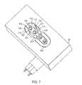
- FIG. 7is a bottom perspective view with the conductive spring elements omitted for clarity
- FIG. 8is a perspective view of the daughtercard and backpanel including PC board patterns
- FIG. 9illustrates a backpanel, mid-panel and daughtercard in an actual application
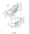
- FIG. 10is an exploded view of a second embodiment of an electrical connector according to the principles of the present invention.
- FIG. 11is an enlarged exploded view of the cable housing interposers according to the present invention.
- FIG. 12is an enlarged view of a front side of the interposer cable housing shown in FIG. 10 according to the present invention.
- FIG. 13Ais a perspective view of the electrical connector of the present invention mounted to a daughtercard with the daughtercard interposer slide being in a retracted position and the backpanel interposer slide being in an extended position;
- FIG. 13Bis a cross-sectional view of conductive spring elements being retained by the Mylar sheet illustrating one end of the conductive spring elements within the interposer slide when the interposer slide is in an extended position;
- FIG. 13Cis a cross-sectional view similar to FIG. 13B illustrating the one end of the conductive spring elements extending beyond the interposer slide when the interposer slide is in a retracted position:
- FIG. 14is a view of the interposer slide mating face
- FIG. 15is an exploded view of a latching guide module according to the present invention.
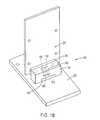
- FIG. 16depicts the electrical connector mounted to a daughtercard with the daughtercard interposer slide in a retracted engaged position and a backpanel interposer slide in an extended unengaged position;
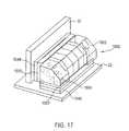
- FIG. 17depicts the electrical connector mounted to a daughtercard and mated to a backpanel
- FIG. 18depicts the guide module, in a fully mated state, with one half of the housing omitted to expose the operating components of the assembly;
- FIG. 19depicts the guide module, in an unmated state, with one half of the housing removed and the guide socket omitted to expose the operating components of the assembly;
- FIG. 20depicts the guide module, in a partially mated state, with one half of the housing removed and the guide socket omitted to expose the operating components of the assembly. This illustrates the movement of the springs and latching devices during the mating process;
- FIG. 21depicts the guide module, from the back side, with the guide pin in the full installed position
- FIG. 22shows the guide module, from the back side, without the guide pin installed and the guide socket removed with the latching devices in the “closed” position
- FIG. 23is the same as FIG. 22 with the guide socket in place with the latching devices in the “closed” position;
- FIG. 24is a view from the same direction as in FIGS. 21-23 . It illustrates the latching devices in the full “open” position during the mating cycle;
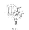
- FIG. 25is a perspective view with the guide pin engaged with a latching device and the cable housing and some latching devices and springs omitted for clarity;
- FIG. 26depicts a second embodiment of a latching mechanism according to the principles of the present invention.
- the interconnect arrangement according to the present inventionprovides a unique twin axial shielded coax structure that has constant impedance from daughtercard interface to the backplane interface.
- the coaxial structureprovides for constant impedance of 65 ohms single ended impedance, 50 ohms odd mode impedance and 100 ohms differential impedance.
- the present inventionprovides a controlled impedance connector through the ability to change the characteristic impedance of the electrical connector by changing the dielectric thickness and constant. This allows custom connectors to be made at different impedance values ranging from 35 ohms to 150 ohms or higher.
- a single ended interconnect pathutilizes one conductor to transfer data.
- a differential interconnect pathutilizes two conductors to transmit the same data.
- the benefit of a differential interconnect path relative to a single ended interconnect pathis that transmission speed increases and noise immunity and electromagnetic interference (EMI) concerns are reduced.
- EMIelectromagnetic interference
- the connector design described hereinwill provide the best known practice for transmitting differential data utilizing copper conductors.
- the sameis true for the single ended version.
- the single ended designutilizes a coaxial conductor to transmit data. This makes it possible to transmit analog (RF) or digital data with signal degradation comparable to that of a coaxial cable.
- FIG. 1Ashows the electrical connector with the over-mold omitted for simplicity of explanation.
- the connector 18is used to electrically connect daughtercard 20 to a backpanel 22 .
- the connector 18includes, as depicted in FIG. 1B , a daughtercard interposer 30 , a backpanel interposer 32 , an over-mold 34 which over-molds semi-rigid twinax or coax cables.
- the over-mold 34is preferably injection molded, for example, from PBT (polybutylene terephthalate). As depicted in FIGS.
- twinax cables 40 , 42are shown for ease of illustration, although it is anticipated that 80 pairs or more of twinax would be used in the electrical connector according to the present invention.
- the presently preferred embodimentuses twinax cable which is bent into a desired shape.
- the present inventionalso contemplates the use of a more rigid construction which is molded in a single piece.
- the center conductoris copper
- the dielectric materialis preferably TeflonTM and the outside jacket is a braid.
- the differential impedance between center conductorsis approximately 100 ohms. Using standard formulas, the impedance can easily be adjusted by varying the distance between center conductors and the dielectric constant for example. In FIG.
- fuzz button arrangements 50 , 52 , 60 , 62are positioned within the interposers 30 , 32 , respectively, and surround ends of the twinax cables 40 , 42 in order to shield the twinax cables and control the impedance of the connector.
- the conductive spring elementmay take various suitable forms.
- the conductive spring elementincludes a “watch band” or POGO” pin, comprising at least one spring-loaded pin capable of being compressed.
- the conductive spring elementincludes a bellows device comprising a plurality of deformable folds which are compressible.
- a further suitable conductive spring elementincludes a Fuzz ButtonTM which comprises a conductor formed into a plug-shaped compressible mesh.
- the conductive spring elementmay include belleville washers or an element comprised of an elastomer loaded with conductive particles.
- the conductive spring elementis plated with gold in order to ensure low, stable RF losses in benign or adverse environments.
- the conductive spring elementmay comprise a single element of one of the above-described, or other types suitable for providing at lest one compliant end or, alternatively, may comprise more than one element, in which case at least one of the elements has at lest one compliant end.
- the present inventionis illustrated with respect to a right angle connector 18 , it should be understood that the present invention is equally usable in other configurations, for example, such as straight configurations between parallel circuit boards. Also, although the use of the present invention is discussed with respect to daughtercards and backpanels, this is only done for convenience and it should be understood that the electrical connector according to the present invention is usable for connecting all types of circuit boards as well as in other high speed applications.
- the connector 18would be assembled by connecting interposer 30 and the backpanel interposer 32 .
- the connector 18is assembled as follows. First, the twinax cables 40 , 42 are formed. All of the conductive spring elements are installed into interposers 30 , 32 . The twinax cables 40 , 42 are then installed into the interposers 30 , 32 . The assembly is then insert molded to form the over-mold 34 which makes the entire electrical connector 18 rigid.
- the over-mold 34is preferably PBT.
- the electrical connector 18could then be connected to the daughtercard 20 using fasteners such as screws, rivets, compression posts, and the like.
- the conductive spring elements 50 , 52 , 60 , 62can be made from a single gold plated fine wire that is compressed into a very small shape.
- the resulting objectis a wire mass having spring performance and demonstrates superior electrical signal conduction from high current DC to microwave frequencies.
- the typical size of a conductive spring elementis 0.01 inch in diameter by 0.060 in length.
- the signal carrying conductive spring elementspreferably have the same outer diameter as the signal carrying center cable.
- the ground contact conductive spring elementsdo not have to be the same diameter or length as the signal carrying conductive spring elements.
- the conductive spring elements 50 , 52 , 60 , 62are employed in the illustrative embodiments, preferably each formed from a strand of metal wire, each strand being wadded together to form a desired cylindrically shaped “button” of material having a density of between 20% and 30%. As depicted in FIGS. 1A and 1B , each wadded-wire connected conductive spring element fits snuggly in openings of the daughtercard interposer 30 and the backpanel interposer 32 .
- the wadded-wire conductive spring elements 50 , 52 , 60 , 62make electrical contact at multiple points when compressed against the contact area. Connectors of this type have significant advantages over other types of connectors and provide connections of high integrity and reliability.
- this mechanical connector elementhas very few associated variables that can affect the quality of the connection.
- the only significant variablesare the size of the connector element and the compressive force used to make the connection, both of which can be accurately controlled by controlling the volume into which the conductive spring element is placed.
- the conductive spring elementscan be epoxied in place using a conductive epoxy.
- the conductive spring elements employed in the illustrative embodimentscan be fabricated using nickel wire, or wire made from alloys such as beryllium and copper, silver and copper, or phosphorous and bronze.
- the compression of the wadded wire of conductive spring elementsis substantially elastic so that, when the compressive force of the twinax cables is removed, the conductive spring elements return to their original shape.
- the wireis randomly compressed into a cylindrical shape and the wire has some spring constant associated with it to provide resiliency when pressure is applied.
- thisallows the electrical connector 18 according to the present invention to be connected and disconnected as many times as is needed.
- the wadded-wire conductive spring elements 50 , 52 , 60 , 62can be manufactured by Technical Wire Products, Inc. of Piscataway, N.J., under the trademark Fuzz ButtonTM.
- FIG. 2differs from FIG. 1 in that two twinax cables 40 , 42 are depicted instead of one. It is important to note that central conductors 120 , 122 are not shielded from each other. However, it is important to shield twinax pairs from each other as depicted in FIG. 2 .
- the backpanel interposer 32has two opposed U-shaped openings 100 , 102 each having an outer U-shaped peripheral wall 110 , 112 , respectively, an inner U-shaped peripheral wall 117 , 118 and a straight wall 114 , 116 , respectively. Walls 114 and 116 face each other as depicted in FIG. 2 .
- a plurality of conductive spring elements 200 , 202 , 204 , 206Inserted into the U-shaped openings are a plurality of conductive spring elements 200 , 202 , 204 , 206 , respectively, each being in a half U-shape as depicted in FIG. 2 .
- conductive spring elements 200 , 202each have a half U-shape and when placed together form a U partially surrounding the twinax cable 40 . It should be understood that other shielding methods could be used to replace the conductive spring elements.
- the twinax cable 40has two central conductors 120 , 122 surrounded by a TeflonTM sheathing 124 .
- signal carrying conductive spring elements 300 - 306(see FIG. 3 ) have the same outer diameters as the two central conductors 120 , 122 .
- the TeflonTM sheathing 124in turn is surrounded by an electrically conductive copper layer which forms a rigid or semi-rigid outer case 128 made of copper and aluminum or a tin filled braiding. Case 128 may be applied using a plating process. As depicted in FIG. 2 , the rigid outer case 128 is stripped away to a length E, thereby exposing the TeflonTM sheathing 124 .
- the TeflonTM sheathing 124is stripped away from the central conductor to a length F. This stripping is done symmetrically on both ends of twinax cables 40 , 42 .
- the conductive spring elements 200 , 202 , 204 , 206are in electrical contact with the layer 128 SO as to form a shield.
- FIG. 3depicts a bottom view of FIG. 2 .
- conductive spring elementsstacked one upon another in a half U-configuration through the thickness of interposer 32 for surrounding and shielding the central twinax leads 120 , 122 , respectively, of twinax cables 40 , 42 .
- a plurality of vertically extending cylindrical conductive spring elements 210 , 212 , 214which are positioned between walls 114 , 116 .
- the conductive spring elements 210 , 214extend through the thickness of interposer 32 and are used to shield twinax cables 40 , 42 from each other. As depicted in FIG.
- twinax cables 40 , 42there is a full 360° shielding for twinax cables 40 , 42 for the stripped away portions of coax cables 40 , 42 which extend through the interposer 32 .
- there are four conductive spring elements 300 , 302 , 304 , 306are in contact with the exposed portions of central conductors 120 , 122 of twinax cables 40 , 42 .
- FIG. 4is an illustration similar to FIGS. 2 and 3 in which the daughtercard interposer 32 has been omitted for clarity.
- These four stacks together with the vertically extending conductive spring elementsform a full 360° shield around twinax cables 40 , 42 .
- the uppermost and lowermost conductive spring elementswill be used in the present invention.
- a stamped and formed metal componentcan be used to electrically connect the uppermost and the lowermost conductive spring elements.
- FIG. 5which is similar to FIG. 4 except that conductive spring elements 200 , 222 , 224 , 226 and 228 have been omitted to show conductive spring elements 306 , 304 in contact with central conductors 122 , 120 , respectively.
- conductive spring elements 300 , 302 and also 304 , 306contact the exposed portions of the central signal carriers 120 , 122 .
- These conductive spring elements 300 - 306are the signal carrying conductive spring elements. It is important that the signal carrying conductive spring elements are substantially the same diameter as the twinax central conductors 120 , 122 to maintain constant impedance. It is also envisioned that other types of spring contacts could be used in the present invention. For example, conductive textiles may be used. Compression springs could also be used. The conductive textile may be injected into the connector replacing the conductive spring elements.
- a central portion 701is formed between the straight wall 114 and the bottom of the outer U-shape wall 110 .
- the central portion 701includes through holes 700 and 702 which receive vertically extending conductive spring elements 300 , 302 .
- a wall 704is formed centrally in the U-shaped area to form a first half U-shaped opening 710 and a second U-shaped opening 712 which receive conductive spring elements 206 , 252 , 254 , 256 , 258 and 204 , 242 , 244 , 246 , 248 , respectively. It is envisioned that there could be a two piece construction and the center support structure could be a separate member constructed of a TeflonTM dielectric. Also, metal plated plastic components could be used.
- a plurality of electrically non-conductive patterns 402 , 404are on the daughtercard 20 and the backpanel 22 , respectively.
- the pattern 402has an electrically conductive area 410 having roughly a figure eight configuration.
- the patternscan be formed using known photolithographic techniques.
- a first non-conductive area 412 and a second non-conductive area 414are spaced apart from each and within an outer periphery 420 of the pattern 402 .
- the first non-conductive area 412has two areas 430 , 432 which include conductive pads 440 , 442 .
- the second non-conductive area 414has two areas 434 , 436 which include conductive pads 444 , 446 .
- Openings 430 , 432 , 434 , 436receive the center conductors 120 , 122 of twinax cables 40 , 42 that extend from the interposer 30 such that conductive spring elements 300 , 302 , 304 , 306 are brought into contact with the conductive pads 440 , 442 , 444 , 446 , respectively.
- conductive spring elements 228 , 238 , 248 and 258will be in electrical contact with the electrically conductive area 410 . In this manner, the conductive spring elements provide a shielding path to ground.
- the electrically conductive area 410is connected to ground plane on the daughtercard and on the backplane.
- openings 430 , 432 , 434 , 436are electrically conductive and are connected to signal paths so that conductive spring elements 306 , 304 , 302 , 300 are in electrical contact therewith when the interposer 30 is used to connect the daughtercard 20 and the backpanel 22 .
- Conductive spring elementsare mounted in the interposer 32 .
- the conductive spring elements 300 , 302 , 304 , 306will be compressed when the daughtercard and backpanel are mated which provides a normal force on the signal line and on the cable.
- the conductive spring elements 300 , 302 , 304 , 306 and 228 , 238 , 248 , 258will be compressed to the board 20 maintaining normal forces with respect to the daughtercard pattern 402 .
- the pattern 404 on the backpanel 22is the same as the pattern 402 and need not be described in detail herein.
- the pattern 404includes an electrically conductive portion 458 and a first non-conductive area 460 and a second non-conductive area 462 .
- the electrical connector 18 of the present inventioncan be connected and reconnected multiple times without degrading the signal contacts 300 , 302 .
- the present inventionis usable not only in daughtercard and backpanel or midplane applications but also in vertical motherboards, parallel boards, and cable link connections. It should also be understood that the present invention could also utilize fiber optic connectors to provide simultaneous optical and electrical signals to be transferred through the connector.
- FIG. 9where a backpanel 700 is depicted connected to a daughtercard 710 .
- the present inventionis also usable in mid-plane connectors such as mid-plane connector 600 depicted in FIG. 9 which is connected to a daughtercard 610 .
- FIG. 10illustrating a second embodiment of an electrical connector 1000 according to the principles of the present invention.
- the electrical conductors 1020 , 1022 , 1024have the same electrical characteristics as electrical conductors as 40 , 42 illustrated with respect to the first embodiment.
- electrical conductor 1024has the shortest path and electrical conductor 1020 has the longest path.
- conductor 1020has a downwardly extending straight portion 1020 ′, an angled portion 1020 ′′ and a horizontally extending straight portion 1020 ′′′.
- the straight portions 1020 ′ and 1020 ′′facilitate installation of ends of the conductor 1020 into cable housing interposers 1030 , 1032 , as explained below.
- the straight portions 1020 ′ and 1020 ′′facilitate installation of ends of the conductor 1020 into cable housing interposers 1030 , 1032 , as explained below.
- the housing for conductors 1020 , 1022 , 1024is explained here, although other sets of conductors are illustrated which have the same housings.
- FIGS. 11-14illustrate additional details of the second embodiment of the present invention.
- the electrical connector 1000includes opposed guide blocks 1002 , 1004 mounted on opposite ends of the electrical connector 1000 , as discussed in detail below.
- the guide blocks 1002 , 1004 and the cable housings 1006 - 1014can either be formed of individual molded parts as depicted and assembled together or can be formed as an over-molded assembly as described previously with respect to FIG. 1 B.
- In between guide blocks 1002 , 1004are a plurality of sets of electrical conductors.
- conductors 1020 , 1022 , 1024form one vertical set of conductors. As illustrated in FIG.
- Each of the electrical conductors 1020 , 1022 , 1024are retained by cable housings 1006 , 1008 and the other electrical conductors are retained by the respective cable housings 1008 - 1014 .
- cable housing 1006is specially adapted to mate with the guide block 1002 using horizontal pins 1006 ′, 1006 ′′ and 1006 ′′′ which interlock with corresponding holes 1002 ′, 1002 ′′ and 1002 ′′′ in the guide block 1002 .
- Housings 1006 , 1008each include recesses 1007 , 1009 , 1011 and 1013 , 1015 , 1017 , respectively.
- Each cable housingincludes a boss and a hole, for example, in cable housing 1008 , there is a boss 1023 and a hole 1025 for interlocking with the cable housing 1006 .
- the electrical connector 1000is a right angle 90 degree electrical connector, although other configurations such as a straight connector can be arranged according to the present invention.
- the electrical connector 1000includes a central twinax or coax portion 1001 which includes all of the copper wire conductors 1020 , 1022 , 1024 and all of the interlocked cable housings 1006 - 1012 , and the guide blocks 1002 , 1004 .
- a central twinax or coax portion 1001which includes all of the copper wire conductors 1020 , 1022 , 1024 and all of the interlocked cable housings 1006 - 1012 , and the guide blocks 1002 , 1004 .
- Opposite ends of the conductors 1020 , 1022 , 1024extend slightly beyond the surfaces 1026 , 1028 , respectively, exposing the outer jacket 128 of each of the twinax conductors 1020 , 1024 .
- the central conductors 120 , 122extend slightly beyond the dielectric 124 and the outer jacket 128 of the twinax conductors
- a rectangular interposer 1030has a front surface 1030 ′ and a back surface 1030 ′′.
- the interposer 1030mates (surface 1030 ′) with the front surface 1026 of assembly 1001 .
- a second rectangular interposer 1032 having a front surface 1032 ′ and a back surface 1032 ′′mates (surface 1032 ′) with the bottom surface 1028 of assembly 1001 .
- the copper wire conductors 120 , 122engage with the interposers 1030 , 1032 as explained below.
- a plurality of conductive spring elements 1034 , 1036are retained by Mylar retainers 1038 , 1040 , respectively.
- the Mylar retainers 1038 , 1040could be made from any suitable material including heat shrinkable plastic.
- the conductive spring elements 1034 , 1036are strategically placed and extend within interposer cable housing 1030 , 1032 and interposer slides 1042 , 1044 , respectively.
- the front surface 1030 ′ of the interposer 1030is rigidly mounted to the front surface 1026 by either press fit studs, ultrasonic welding or epoxy.
- a pair of opposed pins 1009 , 1009 ′extend from the surface 1026 and the guide blocks 1002 , 1004 , respectively, into recessed holes which (not shown) extend inwardly from the surface 1030 ′.
- the pins 1009 , 1009 ′keep the interposer 1030 aligned with the cable housings 1006 - 1014 .
- Pinsextend from the surface 1026 of the guide blocks 1002 , 1004 to keep the interposer 1032 aligned with the cable housings 1006 - 1014 .
- the conductive spring elements 1034 , 1036include ground contact conductive spring elements and signal carrying conductive spring elements as explained below.
- a pair of guide pins 1046 , 1048are provided on the backpanel for mounting the electrical connector 1000 thereto.
- Guide pins 1046 , 1048extend through holes 1050 , 1035 and 1048 , 1033 , respectively, and mate with the latching mechanisms described below.
- a cylindrical guide socket body 1003extends from the guide block 1002 for receiving the guide pin 1048 .
- Guide block 1004has a similar guide socket body (not shown) for receiving guide pin 1046 .
- the guide blocks 1002 , 1004each have a threaded insert 1027 , 1029 , respectively, positioned at right angles from the guide socket body 1003 and aligned with corresponding holes 1061 , 1063 in interposer 1030 and holes 1080 , 1082 in the interposer slide 1042 . Threaded fasteners extend from the daughtercard to fasten the electrical connector 1000 to be threaded into the threaded inserts 1027 , 1029 .
- the Mylar sheet 1038includes a plurality of stamped holes.
- the stamped holesare in a specific pattern for retaining and placing the conductive spring elements in holes in the interposers 1030 , 1032 and the interposer slides 1042 , 1044 .
- the holes used to retain the signal carrying conductive spring elementsmust be held to tight tolerances to hold the conductive spring elements securely yet not so tight to overly compress the conductive spring elements and significantly change the outer diameter thereof.
- Stamped holes 1070 , 1072 , 1074 and 1076are in vertical alignment for receiving retaining tines 1090 , 1092 , 1094 , 1096 in the interposer 1030 .
- the holes 1404 , 1406 and the retaining tines 1090 - 1096maintain the interposer slide 1042 in alignment with the interposer 1030 .
- the retaining tines 1090 - 1096are of sufficient length to permit the interposer slide 1042 to be biased into the extended position by springs 1091 , 1093 mounted in holes 1095 , 1097 in the surface 1030 ′′ of the interposer 1030 .
- the retaining tines 1090 - 1096will be flush or below surface 1092 in the retracted position.
- the conductive spring elements 1034maintain the alignment of the Mylar sheet 1038 relative to the interposer 1030 and the interposer slide 1042 .
- the interposer 1030includes a top set of holes 1110 for receiving the leads of conductor 1020 , middle holes 1112 for receiving the center leads of conductor 1022 and a bottom set of holes 1114 for receiving the leads of the conductor 1024 .
- Each interposerhas multiple ground holes, for example, four ground holes, into which conductive spring elements are placed to make contact with the outer conductive layer 128 of each of the conductors 1020 , 1022 , 1024 . For example, as depicted in FIG.
- the interposer 1030has holes 1120 , 1122 , 1124 , 1126 .
- the Mylar sheethas corresponding boles 1130 , 1132 , 1134 , 1136 .
- Each interposer 1030 , 1032includes a plurality of recesses shaped to match the exterior of each of the conductors 1020 , 1022 , 1024 .
- the electrical conductorshave a straight center section and rounded outer sections.
- the conductive spring elements placed in holes 1130 , 1132 , 1134 , 1136will be in contact with the outer jacket 128 of the conductor and will provide a ground path and electrical shield between adjacent twinax cables.
- the recess 1150extends inwardly from front surface 1032 ′ of the interposer 1032 .
- the recess 1150is formed by opposed curved walls 1160 , 1162 connected by straight sections 1170 , 1172 .
- the straight sections 1170 , 1172as depicted extend horizontally.
- the recess 1150is shaped to receive the outer jacket 128 of the twinax cable.
- interposer 1032is depicted in large scale. It should be understood that interposers 1030 , 1032 are identical except for the opposed holes used for the guide pins 1046 , 1048 which extend through interposer 1032 into guide blocks 1002 , 1004 , respectively.
- the holes 1048 , 1050are offset relative to a longitudinal centerline of the interposer slide 1044 as are holes 1033 , 1035 which are aligned therewith.
- the holes 1066 , 1068 in the interposer 1030are on the centerline as are the holes in the interposer slide 1048 .
- Each central conductor 120 , 122have multiple conductive spring elements associated with it.
- a front surface of the insulator 124can bottom out in the recess 1150 .
- Holes 1280 - 1284are blind holes and intersect with the periphery of the recess 1150 .
- One ground contactpreferably a conductive spring element (not shown) is installed in the holes 1250 - 1256 and are used as ground contacts with the electrically conductive outer jacket 128 of the central conductor.
- Four ground contactsprovide excellent shielding. Additional holes and conductive spring elements can be added to enhance cross-talk reduction.
- hole 1250is centrally located between signal carrying conductive spring elements 1260 , 1262 .
- Hole 1254is offset relative to the center of recess 1150 closer to hole 1260 , whereas in the adjoining recess 1152 , hole 1270 is offset in the opposite direction. It should be noted that excellent electrical shielding is achieved without having to provide 360 degree coverage of each of the twinax cables. Thus, adjacent vertically aligned recesses have offset holes for conductive spring elements. By offsetting the holes, a greater percentage of the circumference is shielded.
- the interposer 130will be spring loaded in a direction away from interposer 1030 . This protects the conductive spring elements from becoming damaged or dislodged during shipping and assembly. It should be understood that the explanation is provided only for the left most set of holes and that the hole pattern repeats.
- the upper most conductor 1020has a set of corresponding holes in the interposer 1042 .
- Hole 1330 for receiving a ground conductive spring elementaligns with hole 1130 in the Mylar sheet and hole 1120 in interposer 1030 .
- Hole 1332aligns with hole 1132 in the Mylar sheet and hole 1122 in the interposer.
- Hole 1334aligns with hole 1134 in the Mylar sheet and hole 1124 in the interposer 1030 .
- Hole 1336aligns with hole 1136 in the Mylar sheet and hole 1126 in interposer 1030 .
- holes 1380align with holes 1080 in the Mylar sheet 1038 and holes 1110 in the interposer 1030 . As depicted in FIG.
- the interposer 1032is illustrated in an extended position in which the conductive spring elements are below the surface 1042 ′′ or at maximum 0.020 above the surface 1042 ′′ and are thereby protected during shipment of the electrical conductor 1000 .
- FIG. 13Athere is a gap between the surface 1032 ′′ of the interposer 1032 and the surface 1042 of the interposer slide.
- the conductive spring elementsare held between the interposer 1030 and the interposer slide 1048 are in contact with the daughtercard 20 .
- the interposer 1032 and the interposer slide 1044are in contact with the backpanel 22 .
- the backpanel printed circuit board with guidehas a plurality of conductive pads 1390 .
- the padshave two signal carrying conductors 1392 , 1394 to be brought into contact with the signal carrying conductive spring elements and an outer ground section 1396 (see FIG. 14 ).
- the pads 1390advantageously do not have to be through plated holes.
- the pads 1390can be surface mount or can have blind vias. By avoiding through plated holes, capacitive effects associated with the holes are reduced and speed can be increased.
- the present inventionadvantageously achieves this shielding using four conductive spring elements connected to ground. These conductive spring elements provide less than 360° shielding but testing has revealed that the level of shielding achieved is sufficient to provide data rates up to 10 Gb/sec and greater.
- the Mylar sheet 1038retains the signal carrying conductive spring elements by compressing the conductive spring elements around the circumference without reducing the outer diameter significantly.
- the diameter of the conductive spring elementsis not changed significantly when compressed into the PC board.
- the force exerted by the conductive spring element in a direction away from the PC boardis relatively small thus allowing the use of the latching mechanism according to the present invention.
- the contact resistance, contact force and compressibilitycan be selected within a wide range to meet the needs of the particular application.
- the overall cumulative contact force of conductive spring elements 1039 , 1036 against contact surfaces 1390is low due to the resilient construction and compressibility of the conductive spring elements.
- the electrical connector according to the present inventionis a compression mount-type
- a unique latching deviceis preferably used with the electrical connector depicted in FIGS. 10-14 .
- the daughtercardsmust not be able to back out of its position in the slot beyond a predetermined distance. This predetermined distance is calculated to ensure the minimum amount of normal force required for an acceptable electrical connection.
- the latching devicecan advantageously be used with all compression mount type connectors and is not limited to the compression type connector described herein.
- a connector guidance moduleis used as device for maintaining a latched position for an interconnect system. The latching device maintains intimate contact between compression mount contacts (conductive spring elements) and the PC board surface without using additional fasteners.
- the latching devicewill operate very similarly to a quick disconnect hose fitting, but will not necessarily have a positive lock requiring more than just enough force to disengage the latch device.
- the spring members and guide pin shapeare designed for mating of the latching device with a minimum of force into a latched position.
- a groove in the guide pin and the latching deviceare designed to require more force to separate than the force generated by he compression contacts against the PC board in a direction to force the latching into an unlatched position.
- latching mechanismwould include but are not limited to replacing the spring members shown with another type of spring, such as a (garter spring) extension coil as depicted in FIG. 26 .
- the latching devices shown herehave a cylindrical cross-section may be replaced with spherical ball component.
- the “groove” in the guide pinis shown here as having a shape to closely match the latching devices' shape, but may be replaced with a simple “V” groove and/or for retention “U” groove.
- FIG. 15a latching guide module 1500 is depicted in an exploded perspective view.
- the latching guide moduleis especially useful when used in combination with the second embodiment depicted in FIGS. 10-14 .
- FIG. 15there is a housing or guide block 1002 and a cable housing block 1006 .
- Housing 1002 and housing 1006each have a portion or half of a through bore 1502 , 1504 , respectively.
- a guide socket body 1510is mounted within the bore formed by 1502 , 1504 and is retained therein as discussed in detail below.
- Each housing 1502 , 1504has a slot 1512 and 1514 (not shown).
- the slots 1512 , 1514are transverse relative to the through bore.
- the guide socket bodyhas three spaced circumferential arcuate slots 1532 (not shown) 1534 and 1536 spaced by walls 1533 , 1535 , 1537 , respectively.
- the latching devices 1522 , 1524 , 1526fit into slots 1532 , 1534 , 1536 , respectively.
- the latching devices 1522 - 1526each have an annular arcuate shape with an inner surface 1522 ′- 1526 ′ and an outer surface 1522 ′′- 1526 ′′.
- the guide pin 1048has an outer cylindrical surface 1550 and an annular groove 1552 .
- the groove 1552has two opposed angled sections 1572 , 1574 and a straight section 1576 connecting the angled sections 1572 , 1574 .
- the inner surfaces 1522 ′- 1526 ′are shaped to match the shape of the annular groove 1552 .
- Three arcuate shaped leaf spring members 1562 , 1564 and 1566are mounted within grooves 1512 , 1514 and are in contact with latching devices 1522 , 1524 , 1526 , respectively.
- the guide socket body 1510is retained in the through bore by a combination of three latching devices 1522 , 1524 , 1526 and the springs 1652 , 1564 , 1566 which bias the latching devices inwardly.
- Each of the twinax cable embodimentsis particularly suitable for differential signaling.
- a driver on one boardsends out two signals and at the receiving board, the difference between the two signals is measured and the actual signal pulse is determined. Because the two conductors are shielded from adjacent twinax cables by the conductive jacket, the twinax cable is especially useful for differential signaling.
- each signalis transmitted on two lines 140 , 142 at the same time. On one, the signal is transmitted as a positive (+) signal, on the other as a negative ( ⁇ ) signal.
- the receiver devicegets two signals. Both signals, however, have been changed by the noise that penetrated through the outer jacket 128 and through the conductive spring element shielding over the signal path.
- the changescame in the form of unwanted voltage added to the wanted signal.
- the unwanted voltageis added to both lines at the same time and by the same amount.
- the essence of the differential systemis that the receiver is designed to subtract the difference between the two signals on the two lines. In doing that, because the noise part of the signal is equal on both lines, the noise cancels out and effectively is eliminated.
- the differential systemworks well if the noise added is equal on the two lines, i.e., the positive (+) and the negative ( ⁇ ). To ensure that the noise affects both of these lines identically, both of them need to occupy theoretically the same physical space. This is true in the present invention in which the two physical lines are within the twinax cable structure.
- the electrical connector 1000is shown engaged with the daughtercard 20 .
- the interposer slide 1042is depicted in a retracted engaged position.
- the interposer slide 1044is shown in an extended non-engaged position.
- the Mylar sheet 1038is in contact with the surface 1030 ′′.
- the interposer slide 1044engages with the top surface of the backpanel 22 , the interposer slide 1044 will slide inwardly to a retracted engaged position.
- the latching mechanismwill engage with the grooves 1552 of pins 1501 , 1503 such that all of the conductive spring elements will be in proper contact with the daughtercard and backpanel pads. This is depicted in FIG. 17 where the electrical connector 1000 is connected to the daughtercard 20 and the backpanel 22 .
- FIG. 18the guide module is depicted in a fully mated state, with one half of the housing removed to better expose the latching mechanism.
- the springs 1564 - 1566 and the latching devices 1564 , 1566are shown in a normal latched engaged position.
- the springs 1562 - 1566bias the latching devices into the groove 1552 .
- FIG. 19depicts the guide module with the latching mechanism in the normal unmated condition.
- FIG. 20depicts the guide module, in a partially mated condition, with one half of the housing removed and the guide socket 1510 omitted to expose the latching mechanism. This illustrates how the springs and latching devices operate during the mating process.
- the spring members 1562 - 1566bias the latching devices 1522 - 1526 inwardly.
- the inner surfaces 1522 ′- 1526 ′are in contact with cylindrical surface 1558 of the guide pin 1550 .
- the latching devices 1522 - 1526are biased radially inwardly as depicted in FIG.
- the guide pin 1501has a tapered top section 1558 to facilitate engagement with the latching devices 1522 - 1526 .
- the insertion forceovercomes the spring bias exerted by spring members 1562 - 1566 such that the latching devices 1522 - 1526 move radially outwardly until the latching devices are biased inwardly into the grooves 1552 .
- the force exerted by the springs 1562 - 1566is sufficient to maintain force on the conductive spring elements to keep the conductive spring elements engaged with the pads.
- FIG. 21depicts the guide module, in a top view with the guide pin 1501 in the fully installed position.
- the grooves 1512 , 1514are illustrated in a top view. Together slots 1512 , 1514 from a hexagonal shape have walls 2102 , 2104 , 2106 , 2108 , 2110 and 2112 .
- springs 1562 , 1564 , 1566are engaged with walls 2104 , 2108 , 2112 respectively.
- FIGS. 15-25there are three latching devices and springs depicted, although any number can be used. As depicted in FIGS. 15-25 , the latching devices and springs are separated by 120°.
- FIG. 22illustrates the latching devices in the normal position.
- FIG. 23is the same as FIG. 22 with the guide socket in place with the latching devices in the “closed position”.
- FIG. 24is a view from the same direction as in FIGS. 21-23 . It illustrates the latching devices in the full “open” position during the mating cycle.
- FIG. 25is a perspective view with the guide pin engaged with a latching device and the cable housing and some latching devices and springs omitted for clarity.
- the spring members 1562 - 1566 and latching devices 1522 - 1526 and the shape of the guide pinare designed to mate electrical connector to the backpanel 22 with a minimum of force.
- the groove 1552 and the guide pin 1501 and the springs 1562 - 1566are designed to require more force to separate the components than the force generated by the compression contacts against the PC board.
- Other options for constructioncan be accomplished using spring members with another type of spring such as a garter spring (extension coil).
- the latching devices shown and describedhave a cylindrical cross-section but the cylindrical cross-section may be replaced with a spherical ball component.
- the groove in the guide pinis shown as having a cliche closely matching the latching device shaved but may be replaced with a simple “V” groove for retention.
- the entire latching devicecan be replaced with a single garter spring 2602 .
- the garter spring 2602is retained in grooves 1512 , 1514 of blocks 1502 , 1504 .
- the spring 2602works similarly to the latching device described with respect to FIG. 15 but is considerably simpler in terms of assembly.
- the garter spring 2602remains in the grooves 1512 , 1514 .
- the garter spring 2602will be retained in the annular groove 1552 thereby maintaining the electrical connector in a mated position with the printed circuit board.
- the electrical connector according to the present inventioncan provide in the range of 80 twinax lines per linear inch in a 20 millimeter card slot.
- this connectorcan be used in the single ended configuration at frequencies to 10 Gb/sec and higher. While these connectors have been described as advantageous to use in backplane systems these connectors also find applicability in many other applications where printed circuits are required to have high density electrical interconnects between adjacent printed circuit boards.
Landscapes
- Engineering & Computer Science (AREA)
- Microelectronics & Electronic Packaging (AREA)
- Details Of Connecting Devices For Male And Female Coupling (AREA)
- Coupling Device And Connection With Printed Circuit (AREA)
- Multi-Conductor Connections (AREA)
Abstract
Description
Claims (28)
Priority Applications (39)
| Application Number | Priority Date | Filing Date | Title |
|---|---|---|---|
| US10/036,796US6843657B2 (en) | 2001-01-12 | 2002-01-07 | High speed, high density interconnect system for differential and single-ended transmission applications |
| SE0200075ASE524822C2 (en) | 2001-01-12 | 2002-01-10 | High-density high-speed interconnection system for differential and asymmetric transmission applications |
| DE10200858ADE10200858A1 (en) | 2001-01-12 | 2002-01-11 | High-density, high-speed connection system for asymmetrical differential transmission applications |
| NO20020142ANO20020142L (en) | 2001-01-12 | 2002-01-11 | Compact interconnection system for signal transmission components |
| NL1019735ANL1019735C2 (en) | 2001-01-12 | 2002-01-11 | High-speed, high-density connection system for differential and single-sided transmission applications. |
| GB0200600AGB2371686B (en) | 2001-01-12 | 2002-01-11 | High speed, high density interconnect system for differential and single-ended transmission applications |
| CA002367600ACA2367600A1 (en) | 2001-01-12 | 2002-01-11 | High speed, high density interconnect system for differential and single-ended transmission applications |
| GB0420652AGB2402561B (en) | 2001-01-12 | 2002-01-11 | High speed, high density interconnect system for differential and single-ended transmission applications |
| BE2002/0015ABE1015431A3 (en) | 2001-01-12 | 2002-01-11 | System interconnect high speed and high density for applications of differential and transmission asymetrique. |
| JP2002039300AJP2002313498A (en) | 2001-01-12 | 2002-01-11 | High speed and high density mutual connection system for use of differential and single end transmission |
| HU0200110AHUP0200110A2 (en) | 2001-01-12 | 2002-01-11 | High speed, high density electronics interconnect system for differential and single wiring transmission applications |
| KR1020020001894AKR20020061122A (en) | 2001-01-12 | 2002-01-12 | High speed, high density interconnect system for differential and single-ended transmission applications |
| FR0200386AFR2832256B1 (en) | 2001-01-12 | 2002-01-14 | HIGH SPEED AND HIGH DENSITY INTERCONNECTING SYSTEM FOR DIFFERENTIAL OR SINGLE END APPLICATIONS |
| MXPA02000497AMXPA02000497A (en) | 2001-01-12 | 2002-01-14 | High speed, high density interconnect system for differential and single-ended transmission applications. |
| US10/234,859US6910897B2 (en) | 2001-01-12 | 2002-09-05 | Interconnection system |
| DE10260287ADE10260287A1 (en) | 2002-01-07 | 2002-12-20 | Interconnection system |
| SE0203852ASE525544C2 (en) | 2002-01-07 | 2002-12-23 | coupling system |
| HU0204558AHUP0204558A2 (en) | 2002-01-07 | 2002-12-28 | Connecting system and method of relizing it |
| ITMI20022787ITMI20022787A1 (en) | 2002-01-07 | 2002-12-30 | INTERCONNECTION SYSTEM |
| TW092100057ATWI246231B (en) | 2002-01-07 | 2003-01-02 | Interconnection system |
| FI20030006AFI20030006A7 (en) | 2002-01-07 | 2003-01-02 | Shared network |
| JP2003000137AJP2003217712A (en) | 2002-01-07 | 2003-01-06 | Interconnection system |
| FR0300073AFR2834587B1 (en) | 2002-01-07 | 2003-01-06 | ELECTRICAL INTERCONNECTION SYSTEM AND METHOD |
| CNB031001335ACN100350677C (en) | 2002-01-07 | 2003-01-06 | Connecting device |
| BE2003/0008ABE1015272A3 (en) | 2002-01-07 | 2003-01-06 | System interconnection. |
| NO20030048ANO20030048L (en) | 2002-01-07 | 2003-01-06 | Interconnection Facilities |
| CA002415979ACA2415979A1 (en) | 2002-01-07 | 2003-01-06 | Interconnection system |
| NL1022316ANL1022316C2 (en) | 2002-01-07 | 2003-01-07 | Connection system. |
| KR10-2003-0000706AKR20030060796A (en) | 2002-01-07 | 2003-01-07 | Interconnection system |
| GB0300313AGB2383904B (en) | 2002-01-07 | 2003-01-07 | Interconnection system |
| MXPA03000109AMXPA03000109A (en) | 2002-01-07 | 2003-01-07 | High speed, high density interconnect system for differential and single-ended transmission applications. |
| HK03100389.6AHK1049234B (en) | 2001-01-12 | 2003-01-15 | High speed, high density interconnect system for differential and single-ended transmission applications |
| HK03106764.8AHK1054819A1 (en) | 2002-01-07 | 2003-09-20 | High speed, high density interconnect system for differential and single-ended transmission systems on backplane / motherboards |
| US10/893,431US7040901B2 (en) | 2001-01-12 | 2004-07-19 | High-speed electrical connector |
| US10/893,430US6979202B2 (en) | 2001-01-12 | 2004-07-19 | High-speed electrical connector |
| US10/971,683US7056128B2 (en) | 2001-01-12 | 2004-10-25 | High speed, high density interconnect system for differential and single-ended transmission systems |
| US11/151,463US7019984B2 (en) | 2001-01-12 | 2005-06-14 | Interconnection system |
| US11/234,107US7101191B2 (en) | 2001-01-12 | 2005-09-26 | High speed electrical connector |
| US11/514,270US7351114B2 (en) | 2001-01-12 | 2006-09-01 | High-speed electrical connector |
Applications Claiming Priority (3)
| Application Number | Priority Date | Filing Date | Title |
|---|---|---|---|
| US26089301P | 2001-01-12 | 2001-01-12 | |
| US32839601P | 2001-10-12 | 2001-10-12 | |
| US10/036,796US6843657B2 (en) | 2001-01-12 | 2002-01-07 | High speed, high density interconnect system for differential and single-ended transmission applications |
Related Child Applications (2)
| Application Number | Title | Priority Date | Filing Date |
|---|---|---|---|
| US10/234,859Continuation-In-PartUS6910897B2 (en) | 2001-01-12 | 2002-09-05 | Interconnection system |
| US10/971,683ContinuationUS7056128B2 (en) | 2001-01-12 | 2004-10-25 | High speed, high density interconnect system for differential and single-ended transmission systems |
Publications (2)
| Publication Number | Publication Date |
|---|---|
| US20020094705A1 US20020094705A1 (en) | 2002-07-18 |
| US6843657B2true US6843657B2 (en) | 2005-01-18 |
Family
ID=27365096
Family Applications (2)
| Application Number | Title | Priority Date | Filing Date |
|---|---|---|---|
| US10/036,796Expired - LifetimeUS6843657B2 (en) | 2001-01-12 | 2002-01-07 | High speed, high density interconnect system for differential and single-ended transmission applications |
| US10/971,683Expired - Fee RelatedUS7056128B2 (en) | 2001-01-12 | 2004-10-25 | High speed, high density interconnect system for differential and single-ended transmission systems |
Family Applications After (1)
| Application Number | Title | Priority Date | Filing Date |
|---|---|---|---|
| US10/971,683Expired - Fee RelatedUS7056128B2 (en) | 2001-01-12 | 2004-10-25 | High speed, high density interconnect system for differential and single-ended transmission systems |
Country Status (14)
| Country | Link |
|---|---|
| US (2) | US6843657B2 (en) |
| JP (1) | JP2002313498A (en) |
| KR (1) | KR20020061122A (en) |
| BE (1) | BE1015431A3 (en) |
| CA (1) | CA2367600A1 (en) |
| DE (1) | DE10200858A1 (en) |
| FR (1) | FR2832256B1 (en) |
| GB (1) | GB2371686B (en) |
| HK (1) | HK1049234B (en) |
| HU (1) | HUP0200110A2 (en) |
| MX (1) | MXPA02000497A (en) |
| NL (1) | NL1019735C2 (en) |
| NO (1) | NO20020142L (en) |
| SE (1) | SE524822C2 (en) |
Cited By (85)
| Publication number | Priority date | Publication date | Assignee | Title |
|---|---|---|---|---|
| US20050048842A1 (en)* | 2001-01-12 | 2005-03-03 | Litton Systems, Inc. | High-speed electrical connector |
| US20050085103A1 (en)* | 2001-01-12 | 2005-04-21 | Litton Systems, Inc. | High speed, high density interconnect system for differential and single-ended transmission systems |
| US20050095896A1 (en)* | 2003-11-05 | 2005-05-05 | Tensolite Company | Zero insertion force high frequency connector |
| US20050101188A1 (en)* | 2001-01-12 | 2005-05-12 | Litton Systems, Inc. | High-speed electrical connector |
| US20050233610A1 (en)* | 2003-11-05 | 2005-10-20 | Tutt Christopher A | High frequency connector assembly |
| US20060091545A1 (en)* | 2004-10-29 | 2006-05-04 | Casher Patrick R | Printed circuit board for high-speed electrical connectors |
| US20060189212A1 (en)* | 2005-02-22 | 2006-08-24 | Avery Hazelton P | Differential signal connector with wafer-style construction |
| US20080132123A1 (en)* | 2004-04-19 | 2008-06-05 | Belden Cdt | Telecommunications Connector |
| US20080298035A1 (en)* | 2006-02-24 | 2008-12-04 | Fujitsu Limitd | Printed circuit board unit |
| US7503768B2 (en) | 2003-11-05 | 2009-03-17 | Tensolite Company | High frequency connector assembly |
| US20090225526A1 (en)* | 2007-08-22 | 2009-09-10 | Teradyne, Inc. | System and method for mounting shielded cables to printed circuit board assemblies |
| US20100022103A1 (en)* | 2008-07-28 | 2010-01-28 | Fujitsu Limited | Connector and transmission wire |
| US20100048058A1 (en)* | 2008-08-19 | 2010-02-25 | Chad William Morgan | Electrical connector with electrically shielded terminals |
| US20100254109A1 (en)* | 2009-03-19 | 2010-10-07 | Olympus Corporation | Mount assembly and method for manufacturing mount assembly |
| US7819667B2 (en) | 2007-08-28 | 2010-10-26 | General Dynamics Advanced Information Systems, Inc. | System and method for interconnecting circuit boards |
| US20110147568A1 (en)* | 2009-12-18 | 2011-06-23 | Irvine Sensors Corporation | High density array module and connector |
| US8109770B2 (en) | 2002-06-24 | 2012-02-07 | Advanced Interconnections Corp. | High speed, high density interconnection device |
| US8687350B2 (en)* | 2011-05-11 | 2014-04-01 | Ez-Tech Corp | Motherboard and case with hidden internal connectors |
| US20140322946A1 (en)* | 2013-04-30 | 2014-10-30 | International Business Machines Corporation | Flex circuit blind attachment apparatus and system |
| US20150132994A1 (en)* | 2012-08-07 | 2015-05-14 | Rosenberger Hochfrquenztechnik Gmbh & Co. Kg | Insertion type connector |
| US9246278B1 (en)* | 2014-08-04 | 2016-01-26 | Tyco Electronics Corporation | Connector module with cable exit region gasket |
| US9774144B2 (en) | 2014-01-22 | 2017-09-26 | Amphenol Corporation | High speed, high density electrical connector with shielded signal paths |
| US20170365942A1 (en)* | 2013-09-04 | 2017-12-21 | Molex, Llc | Connector system with cable by-pass |
| US20170374739A1 (en)* | 2016-06-22 | 2017-12-28 | R&D Circuits, Inc. | Trace anywhere interconnect |
| US10056706B2 (en) | 2013-02-27 | 2018-08-21 | Molex, Llc | High speed bypass cable for use with backplanes |
| US10135211B2 (en) | 2015-01-11 | 2018-11-20 | Molex, Llc | Circuit board bypass assemblies and components therefor |
| US10141676B2 (en) | 2015-07-23 | 2018-11-27 | Amphenol Corporation | Extender module for modular connector |
| US10170869B2 (en) | 2014-11-12 | 2019-01-01 | Amphenol Corporation | Very high speed, high density electrical interconnection system with impedance control in mating region |
| US20190050311A1 (en)* | 2017-08-11 | 2019-02-14 | Seagate Technology Llc | Routing of conductive traces in a printed circuit board |
| USRE47342E1 (en) | 2009-01-30 | 2019-04-09 | Molex, Llc | High speed bypass cable assembly |
| US10305224B2 (en) | 2016-05-18 | 2019-05-28 | Amphenol Corporation | Controlled impedance edged coupled connectors |
| US10367280B2 (en) | 2015-01-11 | 2019-07-30 | Molex, Llc | Wire to board connectors suitable for use in bypass routing assemblies |
| US10424878B2 (en) | 2016-01-11 | 2019-09-24 | Molex, Llc | Cable connector assembly |
| US10424856B2 (en) | 2016-01-11 | 2019-09-24 | Molex, Llc | Routing assembly and system using same |
| US10720735B2 (en) | 2016-10-19 | 2020-07-21 | Amphenol Corporation | Compliant shield for very high speed, high density electrical interconnection |
| US10739828B2 (en) | 2015-05-04 | 2020-08-11 | Molex, Llc | Computing device using bypass assembly |
| US10931062B2 (en) | 2018-11-21 | 2021-02-23 | Amphenol Corporation | High-frequency electrical connector |
| US11057995B2 (en)* | 2018-06-11 | 2021-07-06 | Amphenol Corporation | Backplane footprint for high speed, high density electrical connectors |
| US11070006B2 (en) | 2017-08-03 | 2021-07-20 | Amphenol Corporation | Connector for low loss interconnection system |
| US11101611B2 (en) | 2019-01-25 | 2021-08-24 | Fci Usa Llc | I/O connector configured for cabled connection to the midboard |
| US11151300B2 (en) | 2016-01-19 | 2021-10-19 | Molex, Llc | Integrated routing assembly and system using same |
| US11189943B2 (en) | 2019-01-25 | 2021-11-30 | Fci Usa Llc | I/O connector configured for cable connection to a midboard |
| US11205877B2 (en) | 2018-04-02 | 2021-12-21 | Ardent Concepts, Inc. | Controlled-impedance compliant cable termination |
| US11316294B2 (en)* | 2017-07-31 | 2022-04-26 | Corning Optical Communications Rf Llc | Miniaturized electrical connector systems |
| US11437762B2 (en) | 2019-02-22 | 2022-09-06 | Amphenol Corporation | High performance cable connector assembly |
| US11444398B2 (en) | 2018-03-22 | 2022-09-13 | Amphenol Corporation | High density electrical connector |
| US11469553B2 (en) | 2020-01-27 | 2022-10-11 | Fci Usa Llc | High speed connector |
| US11522310B2 (en) | 2012-08-22 | 2022-12-06 | Amphenol Corporation | High-frequency electrical connector |
| US11546983B2 (en) | 2014-11-21 | 2023-01-03 | Amphenol Corporation | Mating backplane for high speed, high density electrical connector |
| US11553589B2 (en) | 2016-03-08 | 2023-01-10 | Amphenol Corporation | Backplane footprint for high speed, high density electrical connectors |
| US11628006B2 (en) | 2018-09-07 | 2023-04-18 | Cilag Gmbh International | Method for energy distribution in a surgical modular energy system |
| US11637389B2 (en) | 2020-01-27 | 2023-04-25 | Amphenol Corporation | Electrical connector with high speed mounting interface |
| US11637403B2 (en) | 2020-01-27 | 2023-04-25 | Amphenol Corporation | Electrical connector with high speed mounting interface |
| US11670879B2 (en) | 2020-01-28 | 2023-06-06 | Fci Usa Llc | High frequency midboard connector |
| US11696789B2 (en) | 2018-09-07 | 2023-07-11 | Cilag Gmbh International | Consolidated user interface for modular energy system |
| US11735852B2 (en) | 2019-09-19 | 2023-08-22 | Amphenol Corporation | High speed electronic system with midboard cable connector |
| US11743665B2 (en) | 2019-03-29 | 2023-08-29 | Cilag Gmbh International | Modular surgical energy system with module positional awareness sensing with time counter |
| US11742601B2 (en) | 2019-05-20 | 2023-08-29 | Amphenol Corporation | High density, high speed electrical connector |
| US11765813B2 (en) | 2016-03-08 | 2023-09-19 | Amphenol Corporation | Backplane footprint for high speed, high density electrical connectors |
| US11799246B2 (en) | 2020-01-27 | 2023-10-24 | Fci Usa Llc | High speed connector |
| USD1002553S1 (en) | 2021-11-03 | 2023-10-24 | Amphenol Corporation | Gasket for connector |
| US11804679B2 (en) | 2018-09-07 | 2023-10-31 | Cilag Gmbh International | Flexible hand-switch circuit |
| US20230378677A1 (en)* | 2022-05-20 | 2023-11-23 | Cisco Technology, Inc. | High speed and high density cable interconnects |
| US11831106B2 (en) | 2016-05-31 | 2023-11-28 | Amphenol Corporation | High performance cable termination |
| US11857252B2 (en) | 2021-03-30 | 2024-01-02 | Cilag Gmbh International | Bezel with light blocking features for modular energy system |
| US11909147B2 (en) | 2022-01-04 | 2024-02-20 | Te Connectivity Solutions Gmbh | Cable connector assembly |
| US11923084B2 (en) | 2018-09-07 | 2024-03-05 | Cilag Gmbh International | First and second communication protocol arrangement for driving primary and secondary devices through a single port |
| US11950860B2 (en) | 2021-03-30 | 2024-04-09 | Cilag Gmbh International | User interface mitigation techniques for modular energy systems |
| US11963727B2 (en) | 2021-03-30 | 2024-04-23 | Cilag Gmbh International | Method for system architecture for modular energy system |
| US11968776B2 (en) | 2021-03-30 | 2024-04-23 | Cilag Gmbh International | Method for mechanical packaging for modular energy system |
| USD1026010S1 (en) | 2019-09-05 | 2024-05-07 | Cilag Gmbh International | Energy module with alert screen with graphical user interface |
| US11978554B2 (en) | 2021-03-30 | 2024-05-07 | Cilag Gmbh International | Radio frequency identification token for wireless surgical instruments |
| US11980411B2 (en) | 2021-03-30 | 2024-05-14 | Cilag Gmbh International | Header for modular energy system |
| US12004824B2 (en) | 2021-03-30 | 2024-06-11 | Cilag Gmbh International | Architecture for modular energy system |
| US12040749B2 (en) | 2021-03-30 | 2024-07-16 | Cilag Gmbh International | Modular energy system with dual amplifiers and techniques for updating parameters thereof |
| US12079460B2 (en) | 2022-06-28 | 2024-09-03 | Cilag Gmbh International | Profiles for modular energy system |
| US12144136B2 (en) | 2018-09-07 | 2024-11-12 | Cilag Gmbh International | Modular surgical energy system with module positional awareness with digital logic |
| US12191612B2 (en) | 2021-05-28 | 2025-01-07 | Japan Aviation Electronics Industry, Limited | Connector and forming method of connector |
| US12228987B2 (en) | 2021-03-30 | 2025-02-18 | Cilag Gmbh International | Method for energy delivery for modular energy system |
| US12235697B2 (en) | 2021-03-30 | 2025-02-25 | Cilag Gmbh International | Backplane connector attachment mechanism for modular energy system |
| USD1067191S1 (en) | 2021-12-14 | 2025-03-18 | Amphenol Corporation | Electrical connector |
| USD1068685S1 (en) | 2021-12-14 | 2025-04-01 | Amphenol Corporation | Electrical connector |
| US12293432B2 (en) | 2021-04-14 | 2025-05-06 | Cilag Gmbh International | Cooperative overlays of interacting instruments which result in both overlays being effected |
| US12369994B2 (en) | 2021-03-30 | 2025-07-29 | Cilag Gmbh International | Modular energy system with multi-energy port splitter for multiple energy devices |
| US12444094B2 (en) | 2022-03-07 | 2025-10-14 | Cilag Gmbh International | Systems and methods for controlling surgical data overlay |
Families Citing this family (36)
| Publication number | Priority date | Publication date | Assignee | Title |
|---|---|---|---|---|
| US7422850B2 (en)* | 2000-05-19 | 2008-09-09 | Eragen Biosciences, Inc. | Materials and methods for detection of nucleic acids |
| US6910897B2 (en) | 2001-01-12 | 2005-06-28 | Litton Systems, Inc. | Interconnection system |
| GB0130635D0 (en)* | 2001-12-21 | 2002-02-06 | Gore W L & Ass Uk | Cable connector |
| US8338713B2 (en)* | 2002-11-16 | 2012-12-25 | Samsung Electronics Co., Ltd. | Cabled signaling system and components thereof |
| US20040094328A1 (en)* | 2002-11-16 | 2004-05-20 | Fjelstad Joseph C. | Cabled signaling system and components thereof |
| WO2005011061A2 (en)* | 2003-07-17 | 2005-02-03 | Litton Systems, Inc. | High-speed electrical connector |
| US6984073B2 (en)* | 2003-10-14 | 2006-01-10 | 3M Innovative Properties Company | Optical and opto-electronic interconnect alignment system |
| US7195518B2 (en)* | 2005-05-02 | 2007-03-27 | Tyco Electronics Corporation | Electrical connector with enhanced jack interface |
| CN200990261Y (en)* | 2006-10-25 | 2007-12-12 | 上海益而益电器制造有限公司 | Electric source line with electricity leakage detecting conductor |
| US7869225B2 (en)* | 2007-04-30 | 2011-01-11 | Freescale Semiconductor, Inc. | Shielding structures for signal paths in electronic devices |
| US8851356B1 (en) | 2008-02-14 | 2014-10-07 | Metrospec Technology, L.L.C. | Flexible circuit board interconnection and methods |
| US11266014B2 (en) | 2008-02-14 | 2022-03-01 | Metrospec Technology, L.L.C. | LED lighting systems and method |
| US10334735B2 (en) | 2008-02-14 | 2019-06-25 | Metrospec Technology, L.L.C. | LED lighting systems and methods |
| US8007286B1 (en)* | 2008-03-18 | 2011-08-30 | Metrospec Technology, Llc | Circuit boards interconnected by overlapping plated through holes portions |
| DE102008001557A1 (en) | 2008-05-05 | 2009-11-12 | Robert Bosch Gmbh | Male connector contacting via intermediate PCBs |
| US20100195302A1 (en)* | 2009-02-03 | 2010-08-05 | Rigby William J | Flexible guiding module |
| US7794233B1 (en)* | 2009-06-09 | 2010-09-14 | Tyco Electronics Corporation | Flexible circuit member for electrically coupling connectors with one another |
| US8653377B2 (en) | 2011-04-05 | 2014-02-18 | Raytheon Company | Microelectronic assemblies |
| USRE46958E1 (en) | 2011-10-24 | 2018-07-17 | Ardent Concepts, Inc. | Controlled-impedance cable termination using compliant interconnect elements |
| EP2771948B1 (en)* | 2011-10-24 | 2018-12-05 | Ardent Concepts Inc. | Controlled-impedance cable termination using compliant interconnect elements |
| USRE47459E1 (en) | 2011-10-24 | 2019-06-25 | Ardent Concepts, Inc. | Controlled-impedance cable termination using compliant interconnect elements |
| US8936495B2 (en)* | 2013-01-08 | 2015-01-20 | Honeywell Federal Manufacturing & Technologies, Llc | Dual contact pogo pin assembly |
| US20140273551A1 (en)* | 2013-03-14 | 2014-09-18 | Molex Incorporated | Cable module connector assembly suitable for use in blind-mate applications |
| WO2015047397A1 (en)* | 2013-09-30 | 2015-04-02 | Hewlett-Packard Development Company, L.P. | Stacking network switches |
| US9312639B2 (en) | 2014-04-15 | 2016-04-12 | Ardent Concepts, Inc. | Controlled-impedance cable termination with compensation for cable expansion and contraction |
| DE202014008844U1 (en) | 2014-11-06 | 2014-11-24 | Rosenberger Hochfrequenztechnik Gmbh & Co. Kg | Electrical interface |
| DE202014009499U1 (en)* | 2014-11-28 | 2015-01-16 | Rosenberger Hochfrequenztechnik Gmbh & Co. Kg | Angled connector for the differential transmission of data signals |
| CN105792515A (en)* | 2014-12-25 | 2016-07-20 | 台达电子工业股份有限公司 | Circuit board assembly and assembling method thereof |
| US10462904B2 (en) | 2015-11-27 | 2019-10-29 | Kyocera Corporation | Electronic component mounting package and electronic device |
| JP6470428B2 (en)* | 2015-11-27 | 2019-02-13 | 京セラ株式会社 | Electronic component mounting package and electronic device |
| US10658772B1 (en) | 2017-08-15 | 2020-05-19 | Adtran, Inc. | Tiered circuit board for interfacing cables and connectors |
| US10849200B2 (en) | 2018-09-28 | 2020-11-24 | Metrospec Technology, L.L.C. | Solid state lighting circuit with current bias and method of controlling thereof |
| CN114126311B (en)* | 2020-08-31 | 2025-08-22 | 中兴通讯股份有限公司 | Cable connection structure, single board assembly, single board assembly connection structure |
| US11411351B2 (en) | 2020-12-27 | 2022-08-09 | GITech, Inc. | Interposer having shielded contacts and traces |
| TWI885449B (en)* | 2022-08-26 | 2025-06-01 | 美商莫仕有限公司 | Cable Harness |
| DE102022134476A1 (en)* | 2022-12-22 | 2024-06-27 | Dr. Fritz Faulhaber GmbH & Co.KG | Method for producing an autoclavable electrical connection, printed circuit board with an autoclavable electrical connection, and electrically connected autoclavable electronic component |
Citations (225)
| Publication number | Priority date | Publication date | Assignee | Title |
|---|---|---|---|---|
| US3035244A (en) | 1959-06-12 | 1962-05-15 | Aveni Anthony | Flexible pin extension adapter plug |
| US3208028A (en) | 1963-04-30 | 1965-09-21 | Ind Electronic Hardware Corp | Multilayer circuitry with interrupted lines |
| US3432801A (en) | 1966-10-31 | 1969-03-11 | Dynamics Corp America | Patchboard programming system |
| US3564343A (en) | 1968-09-24 | 1971-02-16 | Reliance Electric Co | Computer programming apparatus |
| US3761842A (en) | 1972-06-01 | 1973-09-25 | Bell Telephone Labor Inc | Twisted pair flat conductor cable with means to equalize impedance and propagation velocity |
| US3825874A (en)* | 1973-07-05 | 1974-07-23 | Itt | Electrical connector |
| US4008941A (en) | 1976-03-04 | 1977-02-22 | Amp Incorporated | Printed circuit board housing system |
| US4017770A (en) | 1974-11-22 | 1977-04-12 | Applicazione Elettrotelefoniche Spa | Connecting device for telecommunication circuits |
| US4148543A (en) | 1978-04-28 | 1979-04-10 | General Dynamics Corporation | Suppressor for electromagnetic interference |
| US4157612A (en) | 1977-12-27 | 1979-06-12 | Bell Telephone Laboratories, Incorporated | Method for improving the transmission properties of a connectorized flat cable interconnection assembly |
| US4175821A (en) | 1978-05-15 | 1979-11-27 | Teradyne, Inc. | Electrical connector |
| US4206963A (en) | 1979-04-20 | 1980-06-10 | Amp Incorporated | Connector filtered adapter assembly |
| US4211466A (en) | 1978-11-21 | 1980-07-08 | Amp Incorporated | Crimped electrical connections for conductors on thin substrates |
| US4265549A (en) | 1979-05-21 | 1981-05-05 | Centronics Data Computer Corp. | Flat flexible printed circuit cable for a print head |
| US4331370A (en) | 1980-04-28 | 1982-05-25 | Amp Incorporated | Connection system for printed circuit boards |
| US4338717A (en) | 1980-09-02 | 1982-07-13 | Augat Inc. | Method for fabricating a light emitting diode display socket |
| US4382653A (en) | 1980-12-04 | 1983-05-10 | Avco Corporation | Connector |
| US4397516A (en) | 1981-05-26 | 1983-08-09 | The Bendix Corporation | Cable termination apparatus |
| US4457574A (en) | 1982-02-05 | 1984-07-03 | Automation Industries, Inc. | Electromagnetically shielded connector |
| US4477022A (en) | 1982-02-23 | 1984-10-16 | Amp Incorporated | Polarizing and latch arrangement for an electrical connector |
| US4571014A (en) | 1984-05-02 | 1986-02-18 | At&T Bell Laboratories | High frequency modular connector |
| US4596432A (en) | 1981-11-20 | 1986-06-24 | Amp Incorporated | Shielded ribbon coax cable assembly |
| US4686607A (en) | 1986-01-08 | 1987-08-11 | Teradyne, Inc. | Daughter board/backplane assembly |
| US4689721A (en) | 1986-01-10 | 1987-08-25 | Trw Inc. | Dual printed circuit board module |
| US4697858A (en) | 1986-02-07 | 1987-10-06 | National Semiconductor Corporation | Active bus backplane |
| US4705332A (en) | 1985-08-05 | 1987-11-10 | Criton Technologies | High density, controlled impedance connectors |
| US4755765A (en) | 1987-01-16 | 1988-07-05 | Teradyne, Inc. | Differential input selector |
| EP0284245A1 (en) | 1987-03-27 | 1988-09-28 | The Whitaker Corporation | High-density, modular, electrical connector |
| US4806107A (en) | 1987-10-16 | 1989-02-21 | American Telephone And Telegraph Company, At&T Bell Laboratories | High frequency connector |
| US4816791A (en) | 1987-11-27 | 1989-03-28 | General Electric Company | Stripline to stripline coaxial transition |
| US4820170A (en) | 1984-12-20 | 1989-04-11 | Amp Incorporated | Layered elastomeric connector and process for its manufacture |
| US4836791A (en) | 1987-11-16 | 1989-06-06 | Amp Incorporated | High density coax connector |
| US4846727A (en) | 1988-04-11 | 1989-07-11 | Amp Incorporated | Reference conductor for improving signal integrity in electrical connectors |
| US4861272A (en) | 1988-03-31 | 1989-08-29 | E. I. Du Pont De Nemours And Company | Impedance controlled connector interface |
| US4867707A (en) | 1987-10-19 | 1989-09-19 | W. L. Gore & Associates, Inc. | Coaxial shield integrated contact connector assembly |
| US4871321A (en) | 1988-03-22 | 1989-10-03 | Teradyne, Inc. | Electrical connector |
| US4891616A (en) | 1988-06-01 | 1990-01-02 | Honeywell Inc. | Parallel planar signal transmission system |
| US4898539A (en) | 1989-02-22 | 1990-02-06 | Amp Incorporated | Surface mount HDI contact |
| US4900258A (en) | 1989-06-12 | 1990-02-13 | Amp Incorporated | Multi-port coaxial printed circuit board connector |
| US4924918A (en) | 1989-03-17 | 1990-05-15 | Lin Ming Fang | Machine for manufacturing button connector and method therefor |
| US4941831A (en) | 1986-05-12 | 1990-07-17 | Minnesota Mining And Manufacturing Co. | Coaxial cable termination system |
| US4947144A (en) | 1988-05-04 | 1990-08-07 | Alcatel N.V. | Distribution device for distributing very high data rate digital signals |
| US4946392A (en) | 1988-08-09 | 1990-08-07 | Amp Incorporated | Coaxial connector in a housing block |
| US4975084A (en) | 1988-10-17 | 1990-12-04 | Amp Incorporated | Electrical connector system |
| US4979903A (en) | 1988-11-01 | 1990-12-25 | E. I. Du Pont De Nemours And Company | Surface mountable contact element and assembly |
| US4988306A (en) | 1989-05-16 | 1991-01-29 | Labinal Components And Systems, Inc. | Low-loss electrical interconnects |
| US5007843A (en) | 1983-05-31 | 1991-04-16 | Trw Inc. | High-density contact area electrical connectors |
| EP0422785A2 (en) | 1989-10-10 | 1991-04-17 | The Whitaker Corporation | Impedance matched backplane connector |
| USRE33611E (en) | 1988-07-01 | 1991-06-11 | Molex Incorporated | Environmentally sealed grounding backshell with strain relief |
| US5027088A (en) | 1989-03-14 | 1991-06-25 | Kabushiki Kaisha Toshiba | Signal wiring board |
| US5037314A (en) | 1989-06-01 | 1991-08-06 | Itt Composants Et Instruments | Connecting assembly for printed circuit boards |
| EP0442643A2 (en) | 1990-02-13 | 1991-08-21 | W.L. GORE & ASSOCIATES (UK) LTD | Shielded connector |
| US5046960A (en) | 1990-12-20 | 1991-09-10 | Amp Incorporated | High density connector system |
| EP0446980A1 (en) | 1990-03-14 | 1991-09-18 | Framatome Connectors Belgium N.V. | Connector assembly for printed circuit boards |
| US5055069A (en) | 1990-06-08 | 1991-10-08 | E. I. Du Pont De Nemours And Company | Connectors with ground structure |
| US5083238A (en) | 1991-02-04 | 1992-01-21 | Motorola, Inc. | High frequency electronic assembly |
| US5104341A (en) | 1989-12-20 | 1992-04-14 | Amp Incorporated | Shielded backplane connector |
| US5114355A (en) | 1990-05-04 | 1992-05-19 | Amp Incorporated | Right angle impedance matched electrical connector |
| US5118300A (en) | 1991-05-23 | 1992-06-02 | Amp Incorporated | Active electrical connector |
| EP0488482A1 (en) | 1990-11-29 | 1992-06-03 | E.I. Du Pont De Nemours And Company | A coax connector module |
| US5119886A (en) | 1989-10-25 | 1992-06-09 | The Texas A&M University System | Heat transfer cylinder |
| US5122064A (en) | 1991-05-23 | 1992-06-16 | Amp Incorporated | Solderless surface-mount electrical connector |
| US5122065A (en) | 1991-08-12 | 1992-06-16 | International Business Machines Corp. | Input output connector with coaxial shielding and strain relief |
| US5127837A (en) | 1989-06-09 | 1992-07-07 | Labinal Components And Systems, Inc. | Electrical connectors and IC chip tester embodying same |
| US5158471A (en) | 1991-12-11 | 1992-10-27 | Amp Incorporated | Power connector with current distribution |
| US5163834A (en) | 1990-12-17 | 1992-11-17 | International Business Machines Corporation | High density connector |
| US5167531A (en) | 1992-03-18 | 1992-12-01 | Amp Incorporated | Stacked electrical connector with diecast housing and drawn shells |
| US5174770A (en) | 1990-11-15 | 1992-12-29 | Amp Incorporated | Multicontact connector for signal transmission |
| US5175928A (en) | 1990-06-11 | 1993-01-05 | Amp Incorporated | Method of manufacturing an electrical connection assembly |
| US5186647A (en) | 1992-02-24 | 1993-02-16 | At&T Bell Laboratories | High frequency electrical connector |
| US5197893A (en) | 1990-03-14 | 1993-03-30 | Burndy Corporation | Connector assembly for printed circuit boards |
| US5215473A (en) | 1992-05-05 | 1993-06-01 | Molex Incorporated | High speed guarded cavity backplane connector |
| US5226835A (en) | 1992-08-06 | 1993-07-13 | At&T Bell Laboratories | Patch plug for cross-connect equipment |
| US5249974A (en) | 1992-09-15 | 1993-10-05 | Pan-International Industrial Corp. | Multi-contact connector |
| US5259773A (en) | 1991-12-23 | 1993-11-09 | Framatome Connectors International | Electrical connector intended for receiving a flat support |
| US5282754A (en) | 1992-09-03 | 1994-02-01 | Northern Telecom Limited | Multi-terminal electrical connectors |
| US5286212A (en) | 1992-03-09 | 1994-02-15 | The Whitaker Corporation | Shielded back plane connector |
| EP0583934A2 (en) | 1992-08-18 | 1994-02-23 | The Whitaker Corporation | High frequency cable connector |
| US5295867A (en) | 1992-12-23 | 1994-03-22 | Itt Corporation | Edge connector shield |
| US5299956A (en) | 1992-03-23 | 1994-04-05 | Superior Modular Products, Inc. | Low cross talk electrical connector system |
| US5316489A (en) | 1992-10-23 | 1994-05-31 | Molex Incorporated | Surface mount electrical connector |
| WO1994016474A1 (en) | 1992-12-31 | 1994-07-21 | Connector Systems Technology N.V. | Interconnection system |
| US5334962A (en) | 1987-09-18 | 1994-08-02 | Q-Dot Inc. | High-speed data supply pathway systems |
| US5340334A (en) | 1993-07-19 | 1994-08-23 | The Whitaker Corporation | Filtered electrical connector |
| US5342211A (en) | 1992-03-09 | 1994-08-30 | The Whitaker Corporation | Shielded back plane connector |
| US5354219A (en) | 1990-12-21 | 1994-10-11 | Vemako Ab | Multipolar screened connector having a common earth |
| US5380216A (en) | 1992-05-11 | 1995-01-10 | The Whitaker Corporation | Cable backpanel interconnection |
| US5387114A (en) | 1993-07-22 | 1995-02-07 | Molex Incorporated | Electrical connector with means for altering circuit characteristics |
| US5388997A (en) | 1993-03-16 | 1995-02-14 | Hewlett-Packard Company | Method and system for producing electrically interconnected circuits |
| US5395249A (en) | 1993-06-01 | 1995-03-07 | Westinghouse Electric Corporation | Solder-free backplane connector |
| US5399105A (en) | 1994-04-29 | 1995-03-21 | The Whitaker Corporation | Conductive shroud for electrical connectors |
| US5401912A (en) | 1993-06-07 | 1995-03-28 | St Microwave Corp., Arizona Operations | Microwave surface mount package |
| US5404117A (en) | 1993-10-01 | 1995-04-04 | Hewlett-Packard Company | Connector for strip-type transmission line to coaxial cable |
| US5414393A (en) | 1992-08-20 | 1995-05-09 | Hubbell Incorporated | Telecommunication connector with feedback |
| EP0654859A1 (en) | 1993-11-19 | 1995-05-24 | Framatome Connectors International | Connector for shielded cables |
| US5429520A (en) | 1993-06-04 | 1995-07-04 | Framatome Connectors International | Connector assembly |
| US5432484A (en) | 1992-08-20 | 1995-07-11 | Hubbell Incorporated | Connector for communication systems with cancelled crosstalk |
| US5443617A (en) | 1993-10-06 | 1995-08-22 | Kawasaki Teitoku Co., Ltd. | Powdery raw material composition for a permanent magnet |
| US5443401A (en) | 1992-02-13 | 1995-08-22 | Framatome Connectors International | Electrical connector for mother and daughter printed circuit boards |
| US5454738A (en) | 1993-10-05 | 1995-10-03 | Thomas & Betts Corporation | Electrical connector having reduced cross-talk |
| US5467040A (en) | 1990-01-16 | 1995-11-14 | Cray Research, Inc. | Method for adjusting clock skew |
| US5479321A (en) | 1992-08-31 | 1995-12-26 | Siemens Aktiengesellschaft | Shielded electrical mounting rack |
| US5483020A (en) | 1994-04-12 | 1996-01-09 | W. L. Gore & Associates, Inc. | Twin-ax cable |
| US5484310A (en) | 1993-04-05 | 1996-01-16 | Teradyne, Inc. | Shielded electrical connector |
| US5490787A (en) | 1994-08-29 | 1996-02-13 | The Whitaker Corporation | Electrical connector with integral supporting structure |
| US5495075A (en) | 1991-01-09 | 1996-02-27 | Burndy Corporation | Coaxial connector |
| US5496183A (en) | 1993-04-06 | 1996-03-05 | The Whitaker Corporation | Prestressed shielding plates for electrical connectors |
| US5501613A (en) | 1993-06-04 | 1996-03-26 | Framatome Connectors International | Connector assembly incorporating superposed connection elements |
| US5513065A (en) | 1992-12-23 | 1996-04-30 | Panduit Corp. | Communication connector with capacitor label |
| US5522727A (en) | 1993-09-17 | 1996-06-04 | Japan Aviation Electronics Industry, Limited | Electrical angle connector of a printed circuit board type having a plurality of connecting conductive strips of a common length |
| US5539360A (en) | 1994-03-11 | 1996-07-23 | Motorola, Inc. | Differential transmission line including a conductor having breaks therein |
| US5547405A (en) | 1993-12-03 | 1996-08-20 | Itt Industries Limited | Crosstalk suppressing connector |
| US5552752A (en)* | 1995-06-02 | 1996-09-03 | Hughes Aircraft Company | Microwave vertical interconnect through circuit with compressible conductor |
| US5552565A (en) | 1995-03-31 | 1996-09-03 | Hewlett-Packard Company | Multiconductor shielded transducer cable |
| US5577935A (en) | 1994-11-03 | 1996-11-26 | Harting Elektronik Gmbh | Coaxial, angular connector for installation on a printed circuit board |
| US5586914A (en) | 1995-05-19 | 1996-12-24 | The Whitaker Corporation | Electrical connector and an associated method for compensating for crosstalk between a plurality of conductors |
| EP0752739A1 (en) | 1995-07-03 | 1997-01-08 | Berg Electronics Manufacturing B.V. | Connector, preferably a right angle connector, with integrated pcb assembly |
| US5597313A (en) | 1986-06-19 | 1997-01-28 | Labinal Components And Systems, Inc. | Electrical connectors |
| US5605477A (en) | 1995-01-13 | 1997-02-25 | The Whitaker Corporation | Flexible etched circuit assembly |
| US5618205A (en) | 1993-04-01 | 1997-04-08 | Trw Inc. | Wideband solderless right-angle RF interconnect |
| US5620340A (en) | 1992-12-31 | 1997-04-15 | Berg Technology, Inc. | Connector with improved shielding |
| US5624268A (en) | 1993-11-10 | 1997-04-29 | The Whitaker Corporation | Electrical connectors using anisotropic conductive films |
| US5626497A (en) | 1994-07-14 | 1997-05-06 | Molex Incorporated | Modular jack type connector |
| WO1997018603A1 (en) | 1995-11-16 | 1997-05-22 | The Whitaker Corporation | Surface mountable electrical connector assembly |
| US5633615A (en) | 1995-12-26 | 1997-05-27 | Hughes Electronics | Vertical right angle solderless interconnects from suspended stripline to three-wire lines on MIC substrates |
| US5647770A (en) | 1995-12-29 | 1997-07-15 | Berg Technology, Inc. | Insert for a modular jack useful for reducing electrical crosstalk |
| US5658156A (en) | 1994-09-30 | 1997-08-19 | Thomas & Betts Corporation | Electrical connector and alignment apparatus for contact pins therefor |
| US5661901A (en) | 1995-07-10 | 1997-09-02 | Micron Technology, Inc. | Method for mounting and electrically interconnecting semiconductor dice |
| US5664968A (en) | 1996-03-29 | 1997-09-09 | The Whitaker Corporation | Connector assembly with shielded modules |
| US5672062A (en) | 1991-01-30 | 1997-09-30 | Labinal Components And Systems, Inc. | Electrical connectors |
| US5674093A (en) | 1996-07-23 | 1997-10-07 | Superior Modular Process Incorporated | Reduced cross talk electrical connector |
| US5697817A (en) | 1994-03-26 | 1997-12-16 | Molex Incorporated | Modular jack type connector |
| US5699228A (en) | 1995-06-06 | 1997-12-16 | Hughes Electronics | Method of interconnecting leadless devices to printed wiring boards and apparatus produced thereby |
| US5700167A (en) | 1996-09-06 | 1997-12-23 | Lucent Technologies | Connector cross-talk compensation |
| US5702258A (en) | 1996-03-28 | 1997-12-30 | Teradyne, Inc. | Electrical connector assembled from wafers |
| US5704794A (en) | 1986-12-29 | 1998-01-06 | Labinal Components And Systems, Inc. | Electrical connectors |
| US5716237A (en) | 1996-06-21 | 1998-02-10 | Lucent Technologies Inc. | Electrical connector with crosstalk compensation |
| US5743765A (en) | 1994-07-22 | 1998-04-28 | Berg Technology, Inc. | Selectively metallized connector with at least one coaxial or twin-axial terminal |
| US5789994A (en) | 1997-02-07 | 1998-08-04 | Hughes Electronics Corporation | Differential nonlinear transmission line circuit |
| US5791947A (en) | 1995-06-07 | 1998-08-11 | The Panda Project | Contact beam for electrical interconnect component |
| US5795191A (en) | 1996-09-11 | 1998-08-18 | Preputnick; George | Connector assembly with shielded modules and method of making same |
| US5795190A (en) | 1995-06-30 | 1998-08-18 | Japan Aviation Electronics Industry Limited | Connector having ground plate for PC cards |
| US5816826A (en) | 1996-06-14 | 1998-10-06 | Texas Instruments Incorporated | Computer circuit board with direct connect peripheral slot assembly |
| US5823795A (en)* | 1996-10-30 | 1998-10-20 | Hewlett-Packard Company | Connector between a daughterboard and a motherboard for high-speed single-ended electrical signals |
| US5828226A (en) | 1996-11-06 | 1998-10-27 | Cerprobe Corporation | Probe card assembly for high density integrated circuits |
| US5834335A (en)* | 1995-09-28 | 1998-11-10 | Texas Instruments Incorporated | Non-metallurgical connection between an integrated circuit and a circuit board or another integrated circuit |
| US5842873A (en) | 1996-05-17 | 1998-12-01 | Radiall | Device for connecting a coaxial cable to a printed circuit card |
| US5886590A (en) | 1997-09-04 | 1999-03-23 | Hughes Electronics Corporation | Microstrip to coax vertical launcher using fuzz button and solderless interconnects |
| US5888096A (en) | 1994-01-25 | 1999-03-30 | The Whitaker Corporation | Electrical connector, housing and contact |
| US5890915A (en) | 1996-05-17 | 1999-04-06 | Minnesota Mining And Manufacturing Company | Electrical and thermal conducting structure with resilient conducting paths |
| US5895276A (en) | 1996-11-22 | 1999-04-20 | The Whitaker Corporation | High speed and high density backplane connector |
| US5931687A (en) | 1996-01-11 | 1999-08-03 | Molex Incorporated | Electrical connector with terminal modules and terminal tail aligning device |
| US5940278A (en) | 1997-04-30 | 1999-08-17 | Hewlett-Packard Company | Backing plate for gate arrays or the like carries auxiliary components and provides probe access to electrical test points |
| US5949656A (en) | 1994-06-01 | 1999-09-07 | Davox Corporation | Electronic assembly interconnection system |
| US5955889A (en) | 1994-05-20 | 1999-09-21 | Fujitsu Limited | Electronic circuit apparatus for transmitting signals through a bus and semiconductor device for generating a predetermined stable voltage |
| US5961355A (en) | 1997-12-17 | 1999-10-05 | Berg Technology, Inc. | High density interstitial connector system |
| US5967850A (en) | 1992-12-01 | 1999-10-19 | Crane, Jr.; Stanford W. | High-density electrical interconnect system |
| US5967844A (en) | 1995-04-04 | 1999-10-19 | Berg Technology, Inc. | Electrically enhanced modular connector for printed wiring board |
| US5967853A (en) | 1997-06-24 | 1999-10-19 | Lucent Technologies Inc. | Crosstalk compensation for electrical connectors |
| US5980321A (en) | 1997-02-07 | 1999-11-09 | Teradyne, Inc. | High speed, high density electrical connector |
| US5984710A (en) | 1996-09-18 | 1999-11-16 | Yazaki Corporation | Shielded wire terminating structure |
| US5993256A (en) | 1997-03-24 | 1999-11-30 | Hosiden Corporation | Integrally molded capped type connector |
| US5993255A (en) | 1997-12-17 | 1999-11-30 | The Whitaker Corporation | Electrical connector with combination terminal guide and terminal position assurance member |
| US5993259A (en) | 1997-02-07 | 1999-11-30 | Teradyne, Inc. | High speed, high density electrical connector |
| US6010373A (en) | 1996-06-26 | 2000-01-04 | Robinson Nugent, Inc. | Electrical connector interlocking apparatus |
| US6012927A (en) | 1995-03-29 | 2000-01-11 | Siemens Aktiengesellschaft | Electrical connector |
| US6039580A (en) | 1998-07-16 | 2000-03-21 | Raytheon Company | RF connector having a compliant contact |
| US6042394A (en) | 1995-04-19 | 2000-03-28 | Berg Technology, Inc. | Right-angle connector |
| US6042388A (en) | 1999-01-19 | 2000-03-28 | Unisys Corporation | Electromechanical module having a thin springy plate for establishing pressed electrical connections |
| US6046410A (en) | 1996-12-23 | 2000-04-04 | General Electric Company | Interface structures for electronic devices |
| US6050842A (en) | 1996-09-27 | 2000-04-18 | The Whitaker Corporation | Electrical connector with paired terminals |
| WO2000024092A1 (en) | 1998-10-19 | 2000-04-27 | Channell Commercial Europe Limited | Electrical connector |
| US6062870A (en) | 1989-05-16 | 2000-05-16 | Labinal Components And Systems, Inc. | Electrical interconnects |
| US6083047A (en) | 1997-01-16 | 2000-07-04 | Berg Technology, Inc. | Modular electrical PCB assembly connector |
| US6123554A (en) | 1999-05-28 | 2000-09-26 | Berg Technology, Inc. | Connector cover with board stiffener |
| US6132244A (en) | 1997-10-22 | 2000-10-17 | Siemens Aktiengesellschaft | RF coaxial angle-connector part and method for its production |
| US6146202A (en) | 1998-08-12 | 2000-11-14 | Robinson Nugent, Inc. | Connector apparatus |
| US6183301B1 (en) | 1997-01-16 | 2001-02-06 | Berg Technology, Inc. | Surface mount connector with integrated PCB assembly |
| EP1087466A2 (en) | 1999-09-22 | 2001-03-28 | Itt Manufacturing Enterprises, Inc. | Electrical connector |
| US6220896B1 (en) | 1999-05-13 | 2001-04-24 | Berg Technology, Inc. | Shielded header |
| US6231391B1 (en) | 1999-08-12 | 2001-05-15 | Robinson Nugent, Inc. | Connector apparatus |
| US6236287B1 (en) | 1999-05-12 | 2001-05-22 | Raytheon Company | Wideband shielded coaxial to microstrip orthogonal launcher using distributed discontinuities |
| US6234807B1 (en) | 2000-01-24 | 2001-05-22 | International Business Machines Corporation | Circuit board connector edge with straddle pattern tab design for impedance-controlled connections |
| US20010003077A1 (en) | 1999-12-03 | 2001-06-07 | Framatome Connectors International | Shielded connector assembly |
| US6247972B1 (en) | 1997-08-14 | 2001-06-19 | Silicon Bandwidth, Inc. | Electrical connector assembly with a female electrical connector having internal flexible contact arm |
| US6264476B1 (en) | 1999-12-09 | 2001-07-24 | High Connection Density, Inc. | Wire segment based interposer for high frequency electrical connection |
| US20010012729A1 (en) | 1999-12-03 | 2001-08-09 | Framatome Connectors International | Shielded connector |
| US20010012704A1 (en) | 1998-07-13 | 2001-08-09 | Benjamin N. Eldridge | Interconnect assemblies and methods |
| US6273753B1 (en)* | 2000-10-19 | 2001-08-14 | Hon Hai Precision Ind. Co., Ltd. | Twinax coaxial flat cable connector assembly |
| US6280201B1 (en)* | 2000-01-21 | 2001-08-28 | Hewlett-Packard Company | Laminated 90-degree connector |
| US6293827B1 (en) | 2000-02-03 | 2001-09-25 | Teradyne, Inc. | Differential signal electrical connector |
| US6305947B1 (en) | 1998-11-19 | 2001-10-23 | Berg Technology, Inc. | Angled coaxial connector module |
| US6307391B1 (en) | 2000-02-23 | 2001-10-23 | Unisys Corporation | Pivoting springy mechanism that opens and closes pressed electrical contacts with a force which is nearly constant over a range of closed positions |
| US6316719B1 (en) | 1998-04-30 | 2001-11-13 | Lockheed Martin Corp. | Fabrication of circuit modules with a transmission line |
| US20010041477A1 (en) | 2000-03-29 | 2001-11-15 | Billman Timothy B. | Electrical connector with grounding system |
| US6347962B1 (en) | 2001-01-30 | 2002-02-19 | Tyco Electronics Corporation | Connector assembly with multi-contact ground shields |
| US20020049229A1 (en) | 1999-04-09 | 2002-04-25 | Mochida Pharmaceutical Co., Ltd. | Agents for treating neuropathic pain |
| US6380485B1 (en)* | 2000-08-08 | 2002-04-30 | International Business Machines Corporation | Enhanced wire termination for twinax wires |
| US20020081869A1 (en) | 2000-08-23 | 2002-06-27 | Abbott Russell M. | High density electrical connector |
| US20020094705A1 (en) | 2001-01-12 | 2002-07-18 | Northrop Grumman Corporation | High speed, high density interconnect system for differential and single-ended transmission applications |
| US20020102869A1 (en) | 2001-01-31 | 2002-08-01 | Ali Hassan O. | Surface mount atttachable land grid array connector and method of forming same |
| US20020102885A1 (en) | 2001-01-30 | 2002-08-01 | Kline Richard Scott | Terminal module having open side for enhanced electrical performance |
| US6435913B1 (en) | 2001-06-15 | 2002-08-20 | Hon Hai Precision Ind. Co., Ltd. | Header connector having two shields therein |
| US6439894B1 (en) | 2001-01-31 | 2002-08-27 | High Connection Density, Inc. | Contact assembly for land grid array interposer or electrical connector |
| US20020127893A1 (en) | 2001-03-06 | 2002-09-12 | Brodsky William L. | Particle distribution interposer and method of manufacture thereof |
| US20020137400A1 (en) | 2000-12-21 | 2002-09-26 | Billman Timothy B. | Electrical connector |
| US20020168898A1 (en) | 2001-05-09 | 2002-11-14 | Billman Timothy B. | Electrical connector having differential pair terminals with equal length |
| US6482038B2 (en) | 2001-02-23 | 2002-11-19 | Fci Americas Technology, Inc. | Header assembly for mounting to a circuit substrate |
| US20020173175A1 (en) | 2001-05-15 | 2002-11-21 | International Business Machines Corporation | Interposer member having apertures for relieving stress and increasing contact compliancy |
| US6491545B1 (en) | 2000-05-05 | 2002-12-10 | Molex Incorporated | Modular shielded coaxial cable connector |
| US20030003803A1 (en) | 2000-12-21 | 2003-01-02 | Billman Timothy B. | Electrical connector |
| US6503103B1 (en) | 1997-02-07 | 2003-01-07 | Teradyne, Inc. | Differential signal electrical connectors |
| US6506076B2 (en) | 2000-02-03 | 2003-01-14 | Teradyne, Inc. | Connector with egg-crate shielding |
| US6524135B1 (en) | 1999-09-20 | 2003-02-25 | 3M Innovative Properties Company | Controlled impedance cable connector |
| US6527587B1 (en) | 1999-04-29 | 2003-03-04 | Fci Americas Technology, Inc. | Header assembly for mounting to a circuit substrate and having ground shields therewithin |
| US6540558B1 (en) | 1995-07-03 | 2003-04-01 | Berg Technology, Inc. | Connector, preferably a right angle connector, with integrated PCB assembly |
| US6565387B2 (en) | 1999-06-30 | 2003-05-20 | Teradyne, Inc. | Modular electrical connector and connector system |
| US6572410B1 (en) | 2002-02-20 | 2003-06-03 | Fci Americas Technology, Inc. | Connection header and shield |
| US20030143894A1 (en) | 2002-01-28 | 2003-07-31 | Kline Richard S. | Connector assembly interface for L-shaped ground shields and differential contact pairs |
| US6602095B2 (en) | 2001-01-25 | 2003-08-05 | Teradyne, Inc. | Shielded waferized connector |
| US6623310B1 (en) | 2002-05-21 | 2003-09-23 | Hon Hai Precision Ind. Co., Ltd. | High density electrical connector assembly with reduced insertion force |
| US20030186594A1 (en) | 2002-03-27 | 2003-10-02 | Davis Wayne Samuel | Electrical connector tie bar |
| US6652319B1 (en) | 2002-05-22 | 2003-11-25 | Hon Hai Precision Ind. Co., Ltd. | High speed connector with matched impedance |
| US20030220021A1 (en) | 2002-05-22 | 2003-11-27 | Whiteman Robert Neil | High speed electrical connector |
| US6663429B1 (en) | 2002-08-29 | 2003-12-16 | Hon Hai Precision Ind. Co., Ltd. | Method for manufacturing high density electrical connector assembly |
Family Cites Families (8)
| Publication number | Priority date | Publication date | Assignee | Title |
|---|---|---|---|---|
| US3025244A (en)* | 1959-12-02 | 1962-03-13 | Gen Electric | White air-fired electroluminescent phosphor |
| US5199906A (en) | 1991-02-11 | 1993-04-06 | Trusty Industrial Co., Ltd. | Electrical connector |
| DE10027556C1 (en) | 2000-06-02 | 2001-11-29 | Harting Kgaa | PCB connector |
| JP2002021876A (en)* | 2000-07-10 | 2002-01-23 | Toyota Industries Corp | Electromagnetic spring clutch |
| US6979202B2 (en) | 2001-01-12 | 2005-12-27 | Litton Systems, Inc. | High-speed electrical connector |
| US6540522B2 (en)* | 2001-04-26 | 2003-04-01 | Tyco Electronics Corporation | Electrical connector assembly for orthogonally mating circuit boards |
| US6431914B1 (en)* | 2001-06-04 | 2002-08-13 | Hon Hai Precision Ind. Co., Ltd. | Grounding scheme for a high speed backplane connector system |
| US6712648B2 (en)* | 2002-07-24 | 2004-03-30 | Litton Systems, Inc. | Laminate electrical interconnect system |
- 2002
- 2002-01-07USUS10/036,796patent/US6843657B2/ennot_activeExpired - Lifetime
- 2002-01-10SESE0200075Apatent/SE524822C2/ennot_activeIP Right Cessation
- 2002-01-11NLNL1019735Apatent/NL1019735C2/ennot_activeIP Right Cessation
- 2002-01-11GBGB0200600Apatent/GB2371686B/ennot_activeExpired - Fee Related
- 2002-01-11HUHU0200110Apatent/HUP0200110A2/enunknown
- 2002-01-11NONO20020142Apatent/NO20020142L/enunknown
- 2002-01-11CACA002367600Apatent/CA2367600A1/ennot_activeAbandoned
- 2002-01-11DEDE10200858Apatent/DE10200858A1/ennot_activeWithdrawn
- 2002-01-11BEBE2002/0015Apatent/BE1015431A3/ennot_activeIP Right Cessation
- 2002-01-11JPJP2002039300Apatent/JP2002313498A/enactivePending
- 2002-01-12KRKR1020020001894Apatent/KR20020061122A/ennot_activeWithdrawn
- 2002-01-14FRFR0200386Apatent/FR2832256B1/ennot_activeExpired - Fee Related
- 2002-01-14MXMXPA02000497Apatent/MXPA02000497A/enactiveIP Right Grant
- 2003
- 2003-01-15HKHK03100389.6Apatent/HK1049234B/ennot_activeIP Right Cessation
- 2004
- 2004-10-25USUS10/971,683patent/US7056128B2/ennot_activeExpired - Fee Related
Patent Citations (263)
| Publication number | Priority date | Publication date | Assignee | Title |
|---|---|---|---|---|
| US3035244A (en) | 1959-06-12 | 1962-05-15 | Aveni Anthony | Flexible pin extension adapter plug |
| US3208028A (en) | 1963-04-30 | 1965-09-21 | Ind Electronic Hardware Corp | Multilayer circuitry with interrupted lines |
| US3432801A (en) | 1966-10-31 | 1969-03-11 | Dynamics Corp America | Patchboard programming system |
| US3564343A (en) | 1968-09-24 | 1971-02-16 | Reliance Electric Co | Computer programming apparatus |
| US3761842A (en) | 1972-06-01 | 1973-09-25 | Bell Telephone Labor Inc | Twisted pair flat conductor cable with means to equalize impedance and propagation velocity |
| US3825874A (en)* | 1973-07-05 | 1974-07-23 | Itt | Electrical connector |
| US4017770A (en) | 1974-11-22 | 1977-04-12 | Applicazione Elettrotelefoniche Spa | Connecting device for telecommunication circuits |
| US4008941A (en) | 1976-03-04 | 1977-02-22 | Amp Incorporated | Printed circuit board housing system |
| US4157612A (en) | 1977-12-27 | 1979-06-12 | Bell Telephone Laboratories, Incorporated | Method for improving the transmission properties of a connectorized flat cable interconnection assembly |
| US4148543A (en) | 1978-04-28 | 1979-04-10 | General Dynamics Corporation | Suppressor for electromagnetic interference |
| US4175821A (en) | 1978-05-15 | 1979-11-27 | Teradyne, Inc. | Electrical connector |
| US4211466A (en) | 1978-11-21 | 1980-07-08 | Amp Incorporated | Crimped electrical connections for conductors on thin substrates |
| US4206963A (en) | 1979-04-20 | 1980-06-10 | Amp Incorporated | Connector filtered adapter assembly |
| US4265549A (en) | 1979-05-21 | 1981-05-05 | Centronics Data Computer Corp. | Flat flexible printed circuit cable for a print head |
| US4331370A (en) | 1980-04-28 | 1982-05-25 | Amp Incorporated | Connection system for printed circuit boards |
| US4338717A (en) | 1980-09-02 | 1982-07-13 | Augat Inc. | Method for fabricating a light emitting diode display socket |
| US4382653A (en) | 1980-12-04 | 1983-05-10 | Avco Corporation | Connector |
| US4397516A (en) | 1981-05-26 | 1983-08-09 | The Bendix Corporation | Cable termination apparatus |
| US4596432A (en) | 1981-11-20 | 1986-06-24 | Amp Incorporated | Shielded ribbon coax cable assembly |
| US4457574A (en) | 1982-02-05 | 1984-07-03 | Automation Industries, Inc. | Electromagnetically shielded connector |
| US4477022A (en) | 1982-02-23 | 1984-10-16 | Amp Incorporated | Polarizing and latch arrangement for an electrical connector |
| US5007843A (en) | 1983-05-31 | 1991-04-16 | Trw Inc. | High-density contact area electrical connectors |
| US4571014A (en) | 1984-05-02 | 1986-02-18 | At&T Bell Laboratories | High frequency modular connector |
| US4820170A (en) | 1984-12-20 | 1989-04-11 | Amp Incorporated | Layered elastomeric connector and process for its manufacture |
| US4705332A (en) | 1985-08-05 | 1987-11-10 | Criton Technologies | High density, controlled impedance connectors |
| US4686607A (en) | 1986-01-08 | 1987-08-11 | Teradyne, Inc. | Daughter board/backplane assembly |
| US4689721A (en) | 1986-01-10 | 1987-08-25 | Trw Inc. | Dual printed circuit board module |
| US4697858A (en) | 1986-02-07 | 1987-10-06 | National Semiconductor Corporation | Active bus backplane |
| US4941831A (en) | 1986-05-12 | 1990-07-17 | Minnesota Mining And Manufacturing Co. | Coaxial cable termination system |
| US5597313A (en) | 1986-06-19 | 1997-01-28 | Labinal Components And Systems, Inc. | Electrical connectors |
| US5704794A (en) | 1986-12-29 | 1998-01-06 | Labinal Components And Systems, Inc. | Electrical connectors |
| US4755765A (en) | 1987-01-16 | 1988-07-05 | Teradyne, Inc. | Differential input selector |
| EP0284245A1 (en) | 1987-03-27 | 1988-09-28 | The Whitaker Corporation | High-density, modular, electrical connector |
| US5334962A (en) | 1987-09-18 | 1994-08-02 | Q-Dot Inc. | High-speed data supply pathway systems |
| US4806107A (en) | 1987-10-16 | 1989-02-21 | American Telephone And Telegraph Company, At&T Bell Laboratories | High frequency connector |
| US4867707A (en) | 1987-10-19 | 1989-09-19 | W. L. Gore & Associates, Inc. | Coaxial shield integrated contact connector assembly |
| US4836791A (en) | 1987-11-16 | 1989-06-06 | Amp Incorporated | High density coax connector |
| US4816791A (en) | 1987-11-27 | 1989-03-28 | General Electric Company | Stripline to stripline coaxial transition |
| US4871321A (en) | 1988-03-22 | 1989-10-03 | Teradyne, Inc. | Electrical connector |
| US4861272A (en) | 1988-03-31 | 1989-08-29 | E. I. Du Pont De Nemours And Company | Impedance controlled connector interface |
| US4846727A (en) | 1988-04-11 | 1989-07-11 | Amp Incorporated | Reference conductor for improving signal integrity in electrical connectors |
| US4947144A (en) | 1988-05-04 | 1990-08-07 | Alcatel N.V. | Distribution device for distributing very high data rate digital signals |
| US4891616A (en) | 1988-06-01 | 1990-01-02 | Honeywell Inc. | Parallel planar signal transmission system |
| USRE33611E (en) | 1988-07-01 | 1991-06-11 | Molex Incorporated | Environmentally sealed grounding backshell with strain relief |
| US4946392A (en) | 1988-08-09 | 1990-08-07 | Amp Incorporated | Coaxial connector in a housing block |
| US4975084A (en) | 1988-10-17 | 1990-12-04 | Amp Incorporated | Electrical connector system |
| US4979903A (en) | 1988-11-01 | 1990-12-25 | E. I. Du Pont De Nemours And Company | Surface mountable contact element and assembly |
| US4898539A (en) | 1989-02-22 | 1990-02-06 | Amp Incorporated | Surface mount HDI contact |
| US5027088A (en) | 1989-03-14 | 1991-06-25 | Kabushiki Kaisha Toshiba | Signal wiring board |
| US4924918A (en) | 1989-03-17 | 1990-05-15 | Lin Ming Fang | Machine for manufacturing button connector and method therefor |
| US4988306A (en) | 1989-05-16 | 1991-01-29 | Labinal Components And Systems, Inc. | Low-loss electrical interconnects |
| US6062870A (en) | 1989-05-16 | 2000-05-16 | Labinal Components And Systems, Inc. | Electrical interconnects |
| US5037314A (en) | 1989-06-01 | 1991-08-06 | Itt Composants Et Instruments | Connecting assembly for printed circuit boards |
| US5127837A (en) | 1989-06-09 | 1992-07-07 | Labinal Components And Systems, Inc. | Electrical connectors and IC chip tester embodying same |
| US4900258A (en) | 1989-06-12 | 1990-02-13 | Amp Incorporated | Multi-port coaxial printed circuit board connector |
| EP0422785A2 (en) | 1989-10-10 | 1991-04-17 | The Whitaker Corporation | Impedance matched backplane connector |
| US5066236A (en) | 1989-10-10 | 1991-11-19 | Amp Incorporated | Impedance matched backplane connector |
| US5119886A (en) | 1989-10-25 | 1992-06-09 | The Texas A&M University System | Heat transfer cylinder |
| US5104341A (en) | 1989-12-20 | 1992-04-14 | Amp Incorporated | Shielded backplane connector |
| US5467040A (en) | 1990-01-16 | 1995-11-14 | Cray Research, Inc. | Method for adjusting clock skew |
| EP0442643A2 (en) | 1990-02-13 | 1991-08-21 | W.L. GORE & ASSOCIATES (UK) LTD | Shielded connector |
| EP0446980A1 (en) | 1990-03-14 | 1991-09-18 | Framatome Connectors Belgium N.V. | Connector assembly for printed circuit boards |
| US5197893A (en) | 1990-03-14 | 1993-03-30 | Burndy Corporation | Connector assembly for printed circuit boards |
| US5114355A (en) | 1990-05-04 | 1992-05-19 | Amp Incorporated | Right angle impedance matched electrical connector |
| US5055069A (en) | 1990-06-08 | 1991-10-08 | E. I. Du Pont De Nemours And Company | Connectors with ground structure |
| US5175928A (en) | 1990-06-11 | 1993-01-05 | Amp Incorporated | Method of manufacturing an electrical connection assembly |
| US5174770A (en) | 1990-11-15 | 1992-12-29 | Amp Incorporated | Multicontact connector for signal transmission |
| US5169343A (en) | 1990-11-29 | 1992-12-08 | E. I. Du Pont De Nemours And Company | Coax connector module |
| EP0488482A1 (en) | 1990-11-29 | 1992-06-03 | E.I. Du Pont De Nemours And Company | A coax connector module |
| USRE36065E (en) | 1990-11-29 | 1999-01-26 | Berg Technology, Inc. | Coax connector module |
| US5163834A (en) | 1990-12-17 | 1992-11-17 | International Business Machines Corporation | High density connector |
| US5046960A (en) | 1990-12-20 | 1991-09-10 | Amp Incorporated | High density connector system |
| US5354219A (en) | 1990-12-21 | 1994-10-11 | Vemako Ab | Multipolar screened connector having a common earth |
| US5495075A (en) | 1991-01-09 | 1996-02-27 | Burndy Corporation | Coaxial connector |
| US5704795A (en) | 1991-01-30 | 1998-01-06 | Labinal Components And Systems, Inc. | Electrical connectors |
| US5788512A (en) | 1991-01-30 | 1998-08-04 | Labinal Components And Systems, Inc. | Electrical connectors |
| US5672062A (en) | 1991-01-30 | 1997-09-30 | Labinal Components And Systems, Inc. | Electrical connectors |
| US5083238A (en) | 1991-02-04 | 1992-01-21 | Motorola, Inc. | High frequency electronic assembly |
| US5122064A (en) | 1991-05-23 | 1992-06-16 | Amp Incorporated | Solderless surface-mount electrical connector |
| US5118300A (en) | 1991-05-23 | 1992-06-02 | Amp Incorporated | Active electrical connector |
| US5122065A (en) | 1991-08-12 | 1992-06-16 | International Business Machines Corp. | Input output connector with coaxial shielding and strain relief |
| US5158471A (en) | 1991-12-11 | 1992-10-27 | Amp Incorporated | Power connector with current distribution |
| US5259773A (en) | 1991-12-23 | 1993-11-09 | Framatome Connectors International | Electrical connector intended for receiving a flat support |
| US5443401A (en) | 1992-02-13 | 1995-08-22 | Framatome Connectors International | Electrical connector for mother and daughter printed circuit boards |
| US5186647A (en) | 1992-02-24 | 1993-02-16 | At&T Bell Laboratories | High frequency electrical connector |
| US5342211A (en) | 1992-03-09 | 1994-08-30 | The Whitaker Corporation | Shielded back plane connector |
| US5286212A (en) | 1992-03-09 | 1994-02-15 | The Whitaker Corporation | Shielded back plane connector |
| US5167531A (en) | 1992-03-18 | 1992-12-01 | Amp Incorporated | Stacked electrical connector with diecast housing and drawn shells |
| US5299956A (en) | 1992-03-23 | 1994-04-05 | Superior Modular Products, Inc. | Low cross talk electrical connector system |
| US5299956B1 (en) | 1992-03-23 | 1995-10-24 | Superior Modular Prod Inc | Low cross talk electrical connector system |
| US5292256A (en) | 1992-05-05 | 1994-03-08 | Molex Incorporated | High speed guarded cavity backplane connector |
| US5215473A (en) | 1992-05-05 | 1993-06-01 | Molex Incorporated | High speed guarded cavity backplane connector |
| US5460533A (en) | 1992-05-11 | 1995-10-24 | The Whitaker Corporation | Cable backpanel interconnection |
| US5380216A (en) | 1992-05-11 | 1995-01-10 | The Whitaker Corporation | Cable backpanel interconnection |
| US5226835A (en) | 1992-08-06 | 1993-07-13 | At&T Bell Laboratories | Patch plug for cross-connect equipment |
| EP0583934A2 (en) | 1992-08-18 | 1994-02-23 | The Whitaker Corporation | High frequency cable connector |
| US5632634A (en) | 1992-08-18 | 1997-05-27 | The Whitaker Corporation | High frequency cable connector |
| US5414393A (en) | 1992-08-20 | 1995-05-09 | Hubbell Incorporated | Telecommunication connector with feedback |
| US5432484A (en) | 1992-08-20 | 1995-07-11 | Hubbell Incorporated | Connector for communication systems with cancelled crosstalk |
| US5479321A (en) | 1992-08-31 | 1995-12-26 | Siemens Aktiengesellschaft | Shielded electrical mounting rack |
| US5282754A (en) | 1992-09-03 | 1994-02-01 | Northern Telecom Limited | Multi-terminal electrical connectors |
| US5249974A (en) | 1992-09-15 | 1993-10-05 | Pan-International Industrial Corp. | Multi-contact connector |
| US5316489A (en) | 1992-10-23 | 1994-05-31 | Molex Incorporated | Surface mount electrical connector |
| US5967850A (en) | 1992-12-01 | 1999-10-19 | Crane, Jr.; Stanford W. | High-density electrical interconnect system |
| US5295867A (en) | 1992-12-23 | 1994-03-22 | Itt Corporation | Edge connector shield |
| US5513065A (en) | 1992-12-23 | 1996-04-30 | Panduit Corp. | Communication connector with capacitor label |
| US5516294A (en) | 1992-12-30 | 1996-05-14 | Berg Technology, Inc. | Coaxial interconnection system |
| US5620340A (en) | 1992-12-31 | 1997-04-15 | Berg Technology, Inc. | Connector with improved shielding |
| WO1994016474A1 (en) | 1992-12-31 | 1994-07-21 | Connector Systems Technology N.V. | Interconnection system |
| US5388997A (en) | 1993-03-16 | 1995-02-14 | Hewlett-Packard Company | Method and system for producing electrically interconnected circuits |
| US5618205A (en) | 1993-04-01 | 1997-04-08 | Trw Inc. | Wideband solderless right-angle RF interconnect |
| US5484310A (en) | 1993-04-05 | 1996-01-16 | Teradyne, Inc. | Shielded electrical connector |
| US5496183A (en) | 1993-04-06 | 1996-03-05 | The Whitaker Corporation | Prestressed shielding plates for electrical connectors |
| US5395249A (en) | 1993-06-01 | 1995-03-07 | Westinghouse Electric Corporation | Solder-free backplane connector |
| US5433618A (en) | 1993-06-04 | 1995-07-18 | Framatome Connectors International | Connector assembly |
| US5501613A (en) | 1993-06-04 | 1996-03-26 | Framatome Connectors International | Connector assembly incorporating superposed connection elements |
| US5429520A (en) | 1993-06-04 | 1995-07-04 | Framatome Connectors International | Connector assembly |
| US5401912A (en) | 1993-06-07 | 1995-03-28 | St Microwave Corp., Arizona Operations | Microwave surface mount package |
| US5340334A (en) | 1993-07-19 | 1994-08-23 | The Whitaker Corporation | Filtered electrical connector |
| US5387114A (en) | 1993-07-22 | 1995-02-07 | Molex Incorporated | Electrical connector with means for altering circuit characteristics |
| US5522727A (en) | 1993-09-17 | 1996-06-04 | Japan Aviation Electronics Industry, Limited | Electrical angle connector of a printed circuit board type having a plurality of connecting conductive strips of a common length |
| US5404117A (en) | 1993-10-01 | 1995-04-04 | Hewlett-Packard Company | Connector for strip-type transmission line to coaxial cable |
| US5454738A (en) | 1993-10-05 | 1995-10-03 | Thomas & Betts Corporation | Electrical connector having reduced cross-talk |
| US5470244A (en) | 1993-10-05 | 1995-11-28 | Thomas & Betts Corporation | Electrical connector having reduced cross-talk |
| US5443617A (en) | 1993-10-06 | 1995-08-22 | Kawasaki Teitoku Co., Ltd. | Powdery raw material composition for a permanent magnet |
| US5624268A (en) | 1993-11-10 | 1997-04-29 | The Whitaker Corporation | Electrical connectors using anisotropic conductive films |
| US5554038A (en) | 1993-11-19 | 1996-09-10 | Framatome Connectors International | Connector for shielded cables |
| EP0654859A1 (en) | 1993-11-19 | 1995-05-24 | Framatome Connectors International | Connector for shielded cables |
| US5547405A (en) | 1993-12-03 | 1996-08-20 | Itt Industries Limited | Crosstalk suppressing connector |
| US5888096A (en) | 1994-01-25 | 1999-03-30 | The Whitaker Corporation | Electrical connector, housing and contact |
| US5539360A (en) | 1994-03-11 | 1996-07-23 | Motorola, Inc. | Differential transmission line including a conductor having breaks therein |
| US5697817A (en) | 1994-03-26 | 1997-12-16 | Molex Incorporated | Modular jack type connector |
| US5483020A (en) | 1994-04-12 | 1996-01-09 | W. L. Gore & Associates, Inc. | Twin-ax cable |
| US5399105A (en) | 1994-04-29 | 1995-03-21 | The Whitaker Corporation | Conductive shroud for electrical connectors |
| US5955889A (en) | 1994-05-20 | 1999-09-21 | Fujitsu Limited | Electronic circuit apparatus for transmitting signals through a bus and semiconductor device for generating a predetermined stable voltage |
| US5949656A (en) | 1994-06-01 | 1999-09-07 | Davox Corporation | Electronic assembly interconnection system |
| US5626497A (en) | 1994-07-14 | 1997-05-06 | Molex Incorporated | Modular jack type connector |
| US5743765A (en) | 1994-07-22 | 1998-04-28 | Berg Technology, Inc. | Selectively metallized connector with at least one coaxial or twin-axial terminal |
| US5490787A (en) | 1994-08-29 | 1996-02-13 | The Whitaker Corporation | Electrical connector with integral supporting structure |
| US5658156A (en) | 1994-09-30 | 1997-08-19 | Thomas & Betts Corporation | Electrical connector and alignment apparatus for contact pins therefor |
| US5577935A (en) | 1994-11-03 | 1996-11-26 | Harting Elektronik Gmbh | Coaxial, angular connector for installation on a printed circuit board |
| US5605477A (en) | 1995-01-13 | 1997-02-25 | The Whitaker Corporation | Flexible etched circuit assembly |
| US6012927A (en) | 1995-03-29 | 2000-01-11 | Siemens Aktiengesellschaft | Electrical connector |
| US5552565A (en) | 1995-03-31 | 1996-09-03 | Hewlett-Packard Company | Multiconductor shielded transducer cable |
| US5967844A (en) | 1995-04-04 | 1999-10-19 | Berg Technology, Inc. | Electrically enhanced modular connector for printed wiring board |
| US6042394A (en) | 1995-04-19 | 2000-03-28 | Berg Technology, Inc. | Right-angle connector |
| US5586914A (en) | 1995-05-19 | 1996-12-24 | The Whitaker Corporation | Electrical connector and an associated method for compensating for crosstalk between a plurality of conductors |
| US5675302A (en) | 1995-06-02 | 1997-10-07 | Hughes Electronics | Microwave compression interconnect using dielectric filled three-wire line with compressible conductors |
| US5552752A (en)* | 1995-06-02 | 1996-09-03 | Hughes Aircraft Company | Microwave vertical interconnect through circuit with compressible conductor |
| US5699228A (en) | 1995-06-06 | 1997-12-16 | Hughes Electronics | Method of interconnecting leadless devices to printed wiring boards and apparatus produced thereby |
| US5791947A (en) | 1995-06-07 | 1998-08-11 | The Panda Project | Contact beam for electrical interconnect component |
| US5795190A (en) | 1995-06-30 | 1998-08-18 | Japan Aviation Electronics Industry Limited | Connector having ground plate for PC cards |
| EP0752739A1 (en) | 1995-07-03 | 1997-01-08 | Berg Electronics Manufacturing B.V. | Connector, preferably a right angle connector, with integrated pcb assembly |
| WO1997002627A1 (en) | 1995-07-03 | 1997-01-23 | Berg Technology, Inc. | Connector, preferably a right angle connector, with integrated pcb assembly |
| US6540558B1 (en) | 1995-07-03 | 2003-04-01 | Berg Technology, Inc. | Connector, preferably a right angle connector, with integrated PCB assembly |
| US5661901A (en) | 1995-07-10 | 1997-09-02 | Micron Technology, Inc. | Method for mounting and electrically interconnecting semiconductor dice |
| US5834335A (en)* | 1995-09-28 | 1998-11-10 | Texas Instruments Incorporated | Non-metallurgical connection between an integrated circuit and a circuit board or another integrated circuit |
| WO1997018603A1 (en) | 1995-11-16 | 1997-05-22 | The Whitaker Corporation | Surface mountable electrical connector assembly |
| US5633615A (en) | 1995-12-26 | 1997-05-27 | Hughes Electronics | Vertical right angle solderless interconnects from suspended stripline to three-wire lines on MIC substrates |
| US5647770A (en) | 1995-12-29 | 1997-07-15 | Berg Technology, Inc. | Insert for a modular jack useful for reducing electrical crosstalk |
| US5931687A (en) | 1996-01-11 | 1999-08-03 | Molex Incorporated | Electrical connector with terminal modules and terminal tail aligning device |
| US5702258A (en) | 1996-03-28 | 1997-12-30 | Teradyne, Inc. | Electrical connector assembled from wafers |
| US5664968A (en) | 1996-03-29 | 1997-09-09 | The Whitaker Corporation | Connector assembly with shielded modules |
| US5842873A (en) | 1996-05-17 | 1998-12-01 | Radiall | Device for connecting a coaxial cable to a printed circuit card |
| US5890915A (en) | 1996-05-17 | 1999-04-06 | Minnesota Mining And Manufacturing Company | Electrical and thermal conducting structure with resilient conducting paths |
| US5816826A (en) | 1996-06-14 | 1998-10-06 | Texas Instruments Incorporated | Computer circuit board with direct connect peripheral slot assembly |
| US5716237A (en) | 1996-06-21 | 1998-02-10 | Lucent Technologies Inc. | Electrical connector with crosstalk compensation |
| US6010373A (en) | 1996-06-26 | 2000-01-04 | Robinson Nugent, Inc. | Electrical connector interlocking apparatus |
| US5674093A (en) | 1996-07-23 | 1997-10-07 | Superior Modular Process Incorporated | Reduced cross talk electrical connector |
| US5700167A (en) | 1996-09-06 | 1997-12-23 | Lucent Technologies | Connector cross-talk compensation |
| US5795191A (en) | 1996-09-11 | 1998-08-18 | Preputnick; George | Connector assembly with shielded modules and method of making same |
| US5984710A (en) | 1996-09-18 | 1999-11-16 | Yazaki Corporation | Shielded wire terminating structure |
| US6050842A (en) | 1996-09-27 | 2000-04-18 | The Whitaker Corporation | Electrical connector with paired terminals |
| US5823795A (en)* | 1996-10-30 | 1998-10-20 | Hewlett-Packard Company | Connector between a daughterboard and a motherboard for high-speed single-ended electrical signals |
| US5828226A (en) | 1996-11-06 | 1998-10-27 | Cerprobe Corporation | Probe card assembly for high density integrated circuits |
| US5895276A (en) | 1996-11-22 | 1999-04-20 | The Whitaker Corporation | High speed and high density backplane connector |
| US6046410A (en) | 1996-12-23 | 2000-04-04 | General Electric Company | Interface structures for electronic devices |
| US6527588B2 (en) | 1997-01-16 | 2003-03-04 | Fci Americas Technology, Inc. | Electrical connector with integrated PCB assembly |
| US6183301B1 (en) | 1997-01-16 | 2001-02-06 | Berg Technology, Inc. | Surface mount connector with integrated PCB assembly |
| US6083047A (en) | 1997-01-16 | 2000-07-04 | Berg Technology, Inc. | Modular electrical PCB assembly connector |
| US6503103B1 (en) | 1997-02-07 | 2003-01-07 | Teradyne, Inc. | Differential signal electrical connectors |
| US20020111068A1 (en) | 1997-02-07 | 2002-08-15 | Cohen Thomas S. | Printed circuit board for differential signal electrical connectors |
| US20010005654A1 (en) | 1997-02-07 | 2001-06-28 | Teradyne, Inc. | High speed, high density electrical connector |
| US6607402B2 (en) | 1997-02-07 | 2003-08-19 | Teradyne, Inc. | Printed circuit board for differential signal electrical connectors |
| US5993259A (en) | 1997-02-07 | 1999-11-30 | Teradyne, Inc. | High speed, high density electrical connector |
| US6379188B1 (en) | 1997-02-07 | 2002-04-30 | Teradyne, Inc. | Differential signal electrical connectors |
| US5789994A (en) | 1997-02-07 | 1998-08-04 | Hughes Electronics Corporation | Differential nonlinear transmission line circuit |
| US6238245B1 (en) | 1997-02-07 | 2001-05-29 | Philip T. Stokoe | High speed, high density electrical connector |
| US6554647B1 (en) | 1997-02-07 | 2003-04-29 | Teradyne, Inc. | Differential signal electrical connectors |
| US5980321A (en) | 1997-02-07 | 1999-11-09 | Teradyne, Inc. | High speed, high density electrical connector |
| US5993256A (en) | 1997-03-24 | 1999-11-30 | Hosiden Corporation | Integrally molded capped type connector |
| US5940278A (en) | 1997-04-30 | 1999-08-17 | Hewlett-Packard Company | Backing plate for gate arrays or the like carries auxiliary components and provides probe access to electrical test points |
| US5967853A (en) | 1997-06-24 | 1999-10-19 | Lucent Technologies Inc. | Crosstalk compensation for electrical connectors |
| US6247972B1 (en) | 1997-08-14 | 2001-06-19 | Silicon Bandwidth, Inc. | Electrical connector assembly with a female electrical connector having internal flexible contact arm |
| US6461197B2 (en) | 1997-08-14 | 2002-10-08 | Silicon Bandwidth, Inc. | Female contact pin including flexible contact portion |
| US5886590A (en) | 1997-09-04 | 1999-03-23 | Hughes Electronics Corporation | Microstrip to coax vertical launcher using fuzz button and solderless interconnects |
| US6132244A (en) | 1997-10-22 | 2000-10-17 | Siemens Aktiengesellschaft | RF coaxial angle-connector part and method for its production |
| US5993255A (en) | 1997-12-17 | 1999-11-30 | The Whitaker Corporation | Electrical connector with combination terminal guide and terminal position assurance member |
| US5961355A (en) | 1997-12-17 | 1999-10-05 | Berg Technology, Inc. | High density interstitial connector system |
| US6316719B1 (en) | 1998-04-30 | 2001-11-13 | Lockheed Martin Corp. | Fabrication of circuit modules with a transmission line |
| US20010012704A1 (en) | 1998-07-13 | 2001-08-09 | Benjamin N. Eldridge | Interconnect assemblies and methods |
| US6039580A (en) | 1998-07-16 | 2000-03-21 | Raytheon Company | RF connector having a compliant contact |
| US20020123266A1 (en) | 1998-08-12 | 2002-09-05 | Ramey Samuel C. | Connector apparatus |
| US6146202A (en) | 1998-08-12 | 2000-11-14 | Robinson Nugent, Inc. | Connector apparatus |
| US20010012730A1 (en) | 1998-08-12 | 2001-08-09 | Ramey Samuel C. | Connector apparatus |
| US6371813B2 (en) | 1998-08-12 | 2002-04-16 | Robinson Nugent, Inc. | Connector apparatus |
| WO2000024092A1 (en) | 1998-10-19 | 2000-04-27 | Channell Commercial Europe Limited | Electrical connector |
| GB2344471A (en) | 1998-10-19 | 2000-06-07 | Channel Commercial Europ Limit | Electrical connector for CATV tap |
| US6305947B1 (en) | 1998-11-19 | 2001-10-23 | Berg Technology, Inc. | Angled coaxial connector module |
| US6042388A (en) | 1999-01-19 | 2000-03-28 | Unisys Corporation | Electromechanical module having a thin springy plate for establishing pressed electrical connections |
| US20020049229A1 (en) | 1999-04-09 | 2002-04-25 | Mochida Pharmaceutical Co., Ltd. | Agents for treating neuropathic pain |
| US6527587B1 (en) | 1999-04-29 | 2003-03-04 | Fci Americas Technology, Inc. | Header assembly for mounting to a circuit substrate and having ground shields therewithin |
| US6236287B1 (en) | 1999-05-12 | 2001-05-22 | Raytheon Company | Wideband shielded coaxial to microstrip orthogonal launcher using distributed discontinuities |
| US20020025721A1 (en) | 1999-05-13 | 2002-02-28 | Berg Technology, Inc. | Shielded header |
| US6220896B1 (en) | 1999-05-13 | 2001-04-24 | Berg Technology, Inc. | Shielded header |
| US6471548B2 (en) | 1999-05-13 | 2002-10-29 | Fci Americas Technology, Inc. | Shielded header |
| US6123554A (en) | 1999-05-28 | 2000-09-26 | Berg Technology, Inc. | Connector cover with board stiffener |
| US6565387B2 (en) | 1999-06-30 | 2003-05-20 | Teradyne, Inc. | Modular electrical connector and connector system |
| US6231391B1 (en) | 1999-08-12 | 2001-05-15 | Robinson Nugent, Inc. | Connector apparatus |
| US6524135B1 (en) | 1999-09-20 | 2003-02-25 | 3M Innovative Properties Company | Controlled impedance cable connector |
| EP1087466A2 (en) | 1999-09-22 | 2001-03-28 | Itt Manufacturing Enterprises, Inc. | Electrical connector |
| US20010003077A1 (en) | 1999-12-03 | 2001-06-07 | Framatome Connectors International | Shielded connector assembly |
| US20010012729A1 (en) | 1999-12-03 | 2001-08-09 | Framatome Connectors International | Shielded connector |
| US6264476B1 (en) | 1999-12-09 | 2001-07-24 | High Connection Density, Inc. | Wire segment based interposer for high frequency electrical connection |
| US6280201B1 (en)* | 2000-01-21 | 2001-08-28 | Hewlett-Packard Company | Laminated 90-degree connector |
| US6234807B1 (en) | 2000-01-24 | 2001-05-22 | International Business Machines Corporation | Circuit board connector edge with straddle pattern tab design for impedance-controlled connections |
| US6506076B2 (en) | 2000-02-03 | 2003-01-14 | Teradyne, Inc. | Connector with egg-crate shielding |
| US6293827B1 (en) | 2000-02-03 | 2001-09-25 | Teradyne, Inc. | Differential signal electrical connector |
| US6307391B1 (en) | 2000-02-23 | 2001-10-23 | Unisys Corporation | Pivoting springy mechanism that opens and closes pressed electrical contacts with a force which is nearly constant over a range of closed positions |
| US6364710B1 (en) | 2000-03-29 | 2002-04-02 | Berg Technology, Inc. | Electrical connector with grounding system |
| US6343955B2 (en) | 2000-03-29 | 2002-02-05 | Berg Technology, Inc. | Electrical connector with grounding system |
| US20010041477A1 (en) | 2000-03-29 | 2001-11-15 | Billman Timothy B. | Electrical connector with grounding system |
| US6491545B1 (en) | 2000-05-05 | 2002-12-10 | Molex Incorporated | Modular shielded coaxial cable connector |
| US6380485B1 (en)* | 2000-08-08 | 2002-04-30 | International Business Machines Corporation | Enhanced wire termination for twinax wires |
| US20020081869A1 (en) | 2000-08-23 | 2002-06-27 | Abbott Russell M. | High density electrical connector |
| US6273753B1 (en)* | 2000-10-19 | 2001-08-14 | Hon Hai Precision Ind. Co., Ltd. | Twinax coaxial flat cable connector assembly |
| US20020137400A1 (en) | 2000-12-21 | 2002-09-26 | Billman Timothy B. | Electrical connector |
| US20030003803A1 (en) | 2000-12-21 | 2003-01-02 | Billman Timothy B. | Electrical connector |
| US20020094705A1 (en) | 2001-01-12 | 2002-07-18 | Northrop Grumman Corporation | High speed, high density interconnect system for differential and single-ended transmission applications |
| GB2371686A (en) | 2001-01-12 | 2002-07-31 | Northrop Grumman Corp | High speed, high density interconnect system for differential and single-ended transmission applications |
| US6602095B2 (en) | 2001-01-25 | 2003-08-05 | Teradyne, Inc. | Shielded waferized connector |
| US20020102885A1 (en) | 2001-01-30 | 2002-08-01 | Kline Richard Scott | Terminal module having open side for enhanced electrical performance |
| US6347962B1 (en) | 2001-01-30 | 2002-02-19 | Tyco Electronics Corporation | Connector assembly with multi-contact ground shields |
| US6461202B2 (en) | 2001-01-30 | 2002-10-08 | Tyco Electronics Corporation | Terminal module having open side for enhanced electrical performance |
| US20020187663A1 (en) | 2001-01-31 | 2002-12-12 | Che-Yu Li | Contact assembly for land grid array interposer or electrical connector |
| US20020102869A1 (en) | 2001-01-31 | 2002-08-01 | Ali Hassan O. | Surface mount atttachable land grid array connector and method of forming same |
| US6439894B1 (en) | 2001-01-31 | 2002-08-27 | High Connection Density, Inc. | Contact assembly for land grid array interposer or electrical connector |
| US6482038B2 (en) | 2001-02-23 | 2002-11-19 | Fci Americas Technology, Inc. | Header assembly for mounting to a circuit substrate |
| US20020127893A1 (en) | 2001-03-06 | 2002-09-12 | Brodsky William L. | Particle distribution interposer and method of manufacture thereof |
| US6551140B2 (en) | 2001-05-09 | 2003-04-22 | Hon Hai Precision Ind. Co., Ltd. | Electrical connector having differential pair terminals with equal length |
| US20020168898A1 (en) | 2001-05-09 | 2002-11-14 | Billman Timothy B. | Electrical connector having differential pair terminals with equal length |
| US20020173175A1 (en) | 2001-05-15 | 2002-11-21 | International Business Machines Corporation | Interposer member having apertures for relieving stress and increasing contact compliancy |
| US6435913B1 (en) | 2001-06-15 | 2002-08-20 | Hon Hai Precision Ind. Co., Ltd. | Header connector having two shields therein |
| US20030143894A1 (en) | 2002-01-28 | 2003-07-31 | Kline Richard S. | Connector assembly interface for L-shaped ground shields and differential contact pairs |
| US6572410B1 (en) | 2002-02-20 | 2003-06-03 | Fci Americas Technology, Inc. | Connection header and shield |
| US20030186594A1 (en) | 2002-03-27 | 2003-10-02 | Davis Wayne Samuel | Electrical connector tie bar |
| US6743057B2 (en) | 2002-03-27 | 2004-06-01 | Tyco Electronics Corporation | Electrical connector tie bar |
| US6623310B1 (en) | 2002-05-21 | 2003-09-23 | Hon Hai Precision Ind. Co., Ltd. | High density electrical connector assembly with reduced insertion force |
| US6652319B1 (en) | 2002-05-22 | 2003-11-25 | Hon Hai Precision Ind. Co., Ltd. | High speed connector with matched impedance |
| US20030220021A1 (en) | 2002-05-22 | 2003-11-27 | Whiteman Robert Neil | High speed electrical connector |
| US20030220019A1 (en) | 2002-05-22 | 2003-11-27 | Billman Timothy B. | High density electrical connector assembly |
| US6663427B1 (en) | 2002-05-22 | 2003-12-16 | Hon Hai Precision Ind. Co., Ltd. | High density electrical connector assembly |
| US6663429B1 (en) | 2002-08-29 | 2003-12-16 | Hon Hai Precision Ind. Co., Ltd. | Method for manufacturing high density electrical connector assembly |
Cited By (174)
| Publication number | Priority date | Publication date | Assignee | Title |
|---|---|---|---|---|
| US7101191B2 (en) | 2001-01-12 | 2006-09-05 | Winchester Electronics Corporation | High speed electrical connector |
| US20050085103A1 (en)* | 2001-01-12 | 2005-04-21 | Litton Systems, Inc. | High speed, high density interconnect system for differential and single-ended transmission systems |
| US20050048842A1 (en)* | 2001-01-12 | 2005-03-03 | Litton Systems, Inc. | High-speed electrical connector |
| US20050101188A1 (en)* | 2001-01-12 | 2005-05-12 | Litton Systems, Inc. | High-speed electrical connector |
| US6979202B2 (en) | 2001-01-12 | 2005-12-27 | Litton Systems, Inc. | High-speed electrical connector |
| US20060019507A1 (en)* | 2001-01-12 | 2006-01-26 | Litton Systems, Inc. | High speed electrical connector |
| US20060292932A1 (en)* | 2001-01-12 | 2006-12-28 | Winchester Electronics Corporation | High-speed electrical connector |
| US7040901B2 (en) | 2001-01-12 | 2006-05-09 | Litton Systems, Inc. | High-speed electrical connector |
| US7056128B2 (en)* | 2001-01-12 | 2006-06-06 | Litton Systems, Inc. | High speed, high density interconnect system for differential and single-ended transmission systems |
| US8109770B2 (en) | 2002-06-24 | 2012-02-07 | Advanced Interconnections Corp. | High speed, high density interconnection device |
| US20100273350A1 (en)* | 2003-11-05 | 2010-10-28 | Christopher Alan Tutt | High frequency connector assembly |
| US20050233610A1 (en)* | 2003-11-05 | 2005-10-20 | Tutt Christopher A | High frequency connector assembly |
| US20060194477A1 (en)* | 2003-11-05 | 2006-08-31 | Tensolite Company | Zero insertion force high frequency connector |
| US7074047B2 (en)* | 2003-11-05 | 2006-07-11 | Tensolite Company | Zero insertion force high frequency connector |
| US7748990B2 (en) | 2003-11-05 | 2010-07-06 | Tensolite, Llc | High frequency connector assembly |
| US7249953B2 (en) | 2003-11-05 | 2007-07-31 | Tensolite Company | Zero insertion force high frequency connector |
| US7997907B2 (en) | 2003-11-05 | 2011-08-16 | Tensolite, Llc | High frequency connector assembly |
| US7503768B2 (en) | 2003-11-05 | 2009-03-17 | Tensolite Company | High frequency connector assembly |
| US7404718B2 (en)* | 2003-11-05 | 2008-07-29 | Tensolite Company | High frequency connector assembly |
| US20050095896A1 (en)* | 2003-11-05 | 2005-05-05 | Tensolite Company | Zero insertion force high frequency connector |
| US20080132123A1 (en)* | 2004-04-19 | 2008-06-05 | Belden Cdt | Telecommunications Connector |
| US7837513B2 (en) | 2004-04-19 | 2010-11-23 | Belden Cdt (Canada) Inc. | Telecommunications connector |
| US8021197B2 (en) | 2004-04-19 | 2011-09-20 | Belden Cdt (Canada) Inc. | Telecommunications connector |
| US7645944B2 (en) | 2004-10-29 | 2010-01-12 | Molex Incorporated | Printed circuit board for high-speed electrical connectors |
| US20060091545A1 (en)* | 2004-10-29 | 2006-05-04 | Casher Patrick R | Printed circuit board for high-speed electrical connectors |
| US7534142B2 (en) | 2005-02-22 | 2009-05-19 | Molex Incorporated | Differential signal connector with wafer-style construction |
| US20060189212A1 (en)* | 2005-02-22 | 2006-08-24 | Avery Hazelton P | Differential signal connector with wafer-style construction |
| US20090011620A1 (en)* | 2005-02-22 | 2009-01-08 | Molex Incorporated | Differential signal connector with wafer-style construction |
| US7422483B2 (en) | 2005-02-22 | 2008-09-09 | Molex Incorproated | Differential signal connector with wafer-style construction |
| US20080009147A1 (en)* | 2005-02-22 | 2008-01-10 | Avery Hazelton P | Circuit board via arrangement for differential signal connector |
| US7782630B2 (en)* | 2006-02-24 | 2010-08-24 | Fujitsu Limited | Printed circuit board unit |
| US20080298035A1 (en)* | 2006-02-24 | 2008-12-04 | Fujitsu Limitd | Printed circuit board unit |
| US20090225526A1 (en)* | 2007-08-22 | 2009-09-10 | Teradyne, Inc. | System and method for mounting shielded cables to printed circuit board assemblies |
| US8115107B2 (en)* | 2007-08-22 | 2012-02-14 | Treadyne, Inc. | System and method for mounting shielded cables to printed circuit board assemblies |
| US7819667B2 (en) | 2007-08-28 | 2010-10-26 | General Dynamics Advanced Information Systems, Inc. | System and method for interconnecting circuit boards |
| US20100022103A1 (en)* | 2008-07-28 | 2010-01-28 | Fujitsu Limited | Connector and transmission wire |
| US20100048058A1 (en)* | 2008-08-19 | 2010-02-25 | Chad William Morgan | Electrical connector with electrically shielded terminals |
| US7789676B2 (en)* | 2008-08-19 | 2010-09-07 | Tyco Electronics Corporation | Electrical connector with electrically shielded terminals |
| USRE48230E1 (en) | 2009-01-30 | 2020-09-29 | Molex, Llc | High speed bypass cable assembly |
| USRE47342E1 (en) | 2009-01-30 | 2019-04-09 | Molex, Llc | High speed bypass cable assembly |
| US9343863B2 (en) | 2009-03-19 | 2016-05-17 | Olympus Corporation | Method for manufacturing mount assembly |
| US20100254109A1 (en)* | 2009-03-19 | 2010-10-07 | Olympus Corporation | Mount assembly and method for manufacturing mount assembly |
| US20110147568A1 (en)* | 2009-12-18 | 2011-06-23 | Irvine Sensors Corporation | High density array module and connector |
| US8687350B2 (en)* | 2011-05-11 | 2014-04-01 | Ez-Tech Corp | Motherboard and case with hidden internal connectors |
| US9379492B2 (en)* | 2012-08-07 | 2016-06-28 | Rosenberger Hochfrequenztechnik Gmbh & Co. Kg | Insertion type connector |
| US20150132994A1 (en)* | 2012-08-07 | 2015-05-14 | Rosenberger Hochfrquenztechnik Gmbh & Co. Kg | Insertion type connector |
| US11901663B2 (en) | 2012-08-22 | 2024-02-13 | Amphenol Corporation | High-frequency electrical connector |
| US11522310B2 (en) | 2012-08-22 | 2022-12-06 | Amphenol Corporation | High-frequency electrical connector |
| US10305204B2 (en) | 2013-02-27 | 2019-05-28 | Molex, Llc | High speed bypass cable for use with backplanes |
| US10056706B2 (en) | 2013-02-27 | 2018-08-21 | Molex, Llc | High speed bypass cable for use with backplanes |
| US10069225B2 (en) | 2013-02-27 | 2018-09-04 | Molex, Llc | High speed bypass cable for use with backplanes |
| US8992241B2 (en)* | 2013-04-30 | 2015-03-31 | International Business Machines Corporation | Flex circuit blind attachment apparatus and system |
| US20140322946A1 (en)* | 2013-04-30 | 2014-10-30 | International Business Machines Corporation | Flex circuit blind attachment apparatus and system |
| US10062984B2 (en) | 2013-09-04 | 2018-08-28 | Molex, Llc | Connector system with cable by-pass |
| US10181663B2 (en)* | 2013-09-04 | 2019-01-15 | Molex, Llc | Connector system with cable by-pass |
| US20170365942A1 (en)* | 2013-09-04 | 2017-12-21 | Molex, Llc | Connector system with cable by-pass |
| US10707626B2 (en) | 2014-01-22 | 2020-07-07 | Amphenol Corporation | Very high speed, high density electrical interconnection system with edge to broadside transition |
| US11688980B2 (en) | 2014-01-22 | 2023-06-27 | Amphenol Corporation | Very high speed, high density electrical interconnection system with broadside subassemblies |
| US9774144B2 (en) | 2014-01-22 | 2017-09-26 | Amphenol Corporation | High speed, high density electrical connector with shielded signal paths |
| US9246278B1 (en)* | 2014-08-04 | 2016-01-26 | Tyco Electronics Corporation | Connector module with cable exit region gasket |
| US11764523B2 (en) | 2014-11-12 | 2023-09-19 | Amphenol Corporation | Very high speed, high density electrical interconnection system with impedance control in mating region |
| US10840649B2 (en) | 2014-11-12 | 2020-11-17 | Amphenol Corporation | Organizer for a very high speed, high density electrical interconnection system |
| US10170869B2 (en) | 2014-11-12 | 2019-01-01 | Amphenol Corporation | Very high speed, high density electrical interconnection system with impedance control in mating region |
| US10855034B2 (en) | 2014-11-12 | 2020-12-01 | Amphenol Corporation | Very high speed, high density electrical interconnection system with impedance control in mating region |
| US11950356B2 (en) | 2014-11-21 | 2024-04-02 | Amphenol Corporation | Mating backplane for high speed, high density electrical connector |
| US11546983B2 (en) | 2014-11-21 | 2023-01-03 | Amphenol Corporation | Mating backplane for high speed, high density electrical connector |
| US10367280B2 (en) | 2015-01-11 | 2019-07-30 | Molex, Llc | Wire to board connectors suitable for use in bypass routing assemblies |
| US11114807B2 (en) | 2015-01-11 | 2021-09-07 | Molex, Llc | Circuit board bypass assemblies and components therefor |
| US10637200B2 (en) | 2015-01-11 | 2020-04-28 | Molex, Llc | Circuit board bypass assemblies and components therefor |
| US11621530B2 (en) | 2015-01-11 | 2023-04-04 | Molex, Llc | Circuit board bypass assemblies and components therefor |
| US10135211B2 (en) | 2015-01-11 | 2018-11-20 | Molex, Llc | Circuit board bypass assemblies and components therefor |
| US10784603B2 (en) | 2015-01-11 | 2020-09-22 | Molex, Llc | Wire to board connectors suitable for use in bypass routing assemblies |
| US10739828B2 (en) | 2015-05-04 | 2020-08-11 | Molex, Llc | Computing device using bypass assembly |
| US11003225B2 (en) | 2015-05-04 | 2021-05-11 | Molex, Llc | Computing device using bypass assembly |
| US10141676B2 (en) | 2015-07-23 | 2018-11-27 | Amphenol Corporation | Extender module for modular connector |
| US10879643B2 (en) | 2015-07-23 | 2020-12-29 | Amphenol Corporation | Extender module for modular connector |
| US11837814B2 (en) | 2015-07-23 | 2023-12-05 | Amphenol Corporation | Extender module for modular connector |
| US11688960B2 (en) | 2016-01-11 | 2023-06-27 | Molex, Llc | Routing assembly and system using same |
| US10424878B2 (en) | 2016-01-11 | 2019-09-24 | Molex, Llc | Cable connector assembly |
| US10797416B2 (en) | 2016-01-11 | 2020-10-06 | Molex, Llc | Routing assembly and system using same |
| US10424856B2 (en) | 2016-01-11 | 2019-09-24 | Molex, Llc | Routing assembly and system using same |
| US11108176B2 (en) | 2016-01-11 | 2021-08-31 | Molex, Llc | Routing assembly and system using same |
| US11151300B2 (en) | 2016-01-19 | 2021-10-19 | Molex, Llc | Integrated routing assembly and system using same |
| US11842138B2 (en) | 2016-01-19 | 2023-12-12 | Molex, Llc | Integrated routing assembly and system using same |
| US11805595B2 (en) | 2016-03-08 | 2023-10-31 | Amphenol Corporation | Backplane footprint for high speed, high density electrical connectors |
| US11765813B2 (en) | 2016-03-08 | 2023-09-19 | Amphenol Corporation | Backplane footprint for high speed, high density electrical connectors |
| US11553589B2 (en) | 2016-03-08 | 2023-01-10 | Amphenol Corporation | Backplane footprint for high speed, high density electrical connectors |
| US10305224B2 (en) | 2016-05-18 | 2019-05-28 | Amphenol Corporation | Controlled impedance edged coupled connectors |
| US11831106B2 (en) | 2016-05-31 | 2023-11-28 | Amphenol Corporation | High performance cable termination |
| US10257930B2 (en)* | 2016-06-22 | 2019-04-09 | R&D Circuits, Inc. | Trace anywhere interconnect |
| US20170374739A1 (en)* | 2016-06-22 | 2017-12-28 | R&D Circuits, Inc. | Trace anywhere interconnect |
| US11387609B2 (en) | 2016-10-19 | 2022-07-12 | Amphenol Corporation | Compliant shield for very high speed, high density electrical interconnection |
| US10720735B2 (en) | 2016-10-19 | 2020-07-21 | Amphenol Corporation | Compliant shield for very high speed, high density electrical interconnection |
| US11316294B2 (en)* | 2017-07-31 | 2022-04-26 | Corning Optical Communications Rf Llc | Miniaturized electrical connector systems |
| TWI806883B (en)* | 2017-07-31 | 2023-07-01 | 美商康寧光纖通信射頻有限責任公司 | Twinaxial cable connector and twinaxial cable assembly |
| US11637401B2 (en) | 2017-08-03 | 2023-04-25 | Amphenol Corporation | Cable connector for high speed in interconnects |
| US11070006B2 (en) | 2017-08-03 | 2021-07-20 | Amphenol Corporation | Connector for low loss interconnection system |
| US11824311B2 (en) | 2017-08-03 | 2023-11-21 | Amphenol Corporation | Connector for low loss interconnection system |
| US20190050311A1 (en)* | 2017-08-11 | 2019-02-14 | Seagate Technology Llc | Routing of conductive traces in a printed circuit board |
| US10638601B2 (en)* | 2017-08-11 | 2020-04-28 | Seagate Technology Llc | Apparatus comprising conductive traces configured to transmit differential signals in printed circuit boards |
| US11444398B2 (en) | 2018-03-22 | 2022-09-13 | Amphenol Corporation | High density electrical connector |
| US11205877B2 (en) | 2018-04-02 | 2021-12-21 | Ardent Concepts, Inc. | Controlled-impedance compliant cable termination |
| US11677188B2 (en) | 2018-04-02 | 2023-06-13 | Ardent Concepts, Inc. | Controlled-impedance compliant cable termination |
| US12171063B2 (en) | 2018-06-11 | 2024-12-17 | Amphenol Corporation | Backplane footprint for high speed, high density electrical connectors |
| US11057995B2 (en)* | 2018-06-11 | 2021-07-06 | Amphenol Corporation | Backplane footprint for high speed, high density electrical connectors |
| US11758656B2 (en) | 2018-06-11 | 2023-09-12 | Amphenol Corporation | Backplane footprint for high speed, high density electrical connectors |
| US12144136B2 (en) | 2018-09-07 | 2024-11-12 | Cilag Gmbh International | Modular surgical energy system with module positional awareness with digital logic |
| US11923084B2 (en) | 2018-09-07 | 2024-03-05 | Cilag Gmbh International | First and second communication protocol arrangement for driving primary and secondary devices through a single port |
| US11684400B2 (en) | 2018-09-07 | 2023-06-27 | Cilag Gmbh International | Grounding arrangement of energy modules |
| US11684401B2 (en) | 2018-09-07 | 2023-06-27 | Cilag Gmbh International | Backplane connector design to connect stacked energy modules |
| US11678925B2 (en) | 2018-09-07 | 2023-06-20 | Cilag Gmbh International | Method for controlling an energy module output |
| US11696791B2 (en) | 2018-09-07 | 2023-07-11 | Cilag Gmbh International | Surgical instrument utilizing drive signal to power secondary function |
| US11696789B2 (en) | 2018-09-07 | 2023-07-11 | Cilag Gmbh International | Consolidated user interface for modular energy system |
| US11696790B2 (en) | 2018-09-07 | 2023-07-11 | Cilag Gmbh International | Adaptably connectable and reassignable system accessories for modular energy system |
| US11950823B2 (en) | 2018-09-07 | 2024-04-09 | Cilag Gmbh International | Regional location tracking of components of a modular energy system |
| US11712280B2 (en) | 2018-09-07 | 2023-08-01 | Cilag Gmbh International | Passive header module for a modular energy system |
| US11628006B2 (en) | 2018-09-07 | 2023-04-18 | Cilag Gmbh International | Method for energy distribution in a surgical modular energy system |
| US12178491B2 (en) | 2018-09-07 | 2024-12-31 | Cilag Gmbh International | Control circuit for controlling an energy module output |
| US11931089B2 (en) | 2018-09-07 | 2024-03-19 | Cilag Gmbh International | Modular surgical energy system with module positional awareness sensing with voltage detection |
| US12042201B2 (en) | 2018-09-07 | 2024-07-23 | Cilag Gmbh International | Method for communicating between modules and devices in a modular surgical system |
| US11666368B2 (en) | 2018-09-07 | 2023-06-06 | Cilag Gmbh International | Method for constructing and using a modular surgical energy system with multiple devices |
| US12376896B2 (en) | 2018-09-07 | 2025-08-05 | Cilag Gmbh International | Power and communication mitigation arrangement for modular surgical energy system |
| US11918269B2 (en) | 2018-09-07 | 2024-03-05 | Cilag Gmbh International | Smart return pad sensing through modulation of near field communication and contact quality monitoring signals |
| US11998258B2 (en) | 2018-09-07 | 2024-06-04 | Cilag Gmbh International | Energy module for driving multiple energy modalities |
| US12369960B2 (en) | 2018-09-07 | 2025-07-29 | Cilag Gmbh International | Method for energy distribution in a surgical modular energy system |
| US12035956B2 (en) | 2018-09-07 | 2024-07-16 | Cilag Gmbh International | Instrument tracking arrangement based on real time clock information |
| US11804679B2 (en) | 2018-09-07 | 2023-10-31 | Cilag Gmbh International | Flexible hand-switch circuit |
| US11806062B2 (en) | 2018-09-07 | 2023-11-07 | Cilag Gmbh International | Surgical modular energy system with a segmented backplane |
| US12239353B2 (en) | 2018-09-07 | 2025-03-04 | Cilag Gmbh International | Energy module for driving multiple energy modalities through a port |
| US11638602B2 (en) | 2018-09-07 | 2023-05-02 | Cilag Gmbh International | Coordinated stackable multi-module surgical system |
| US11896279B2 (en) | 2018-09-07 | 2024-02-13 | Cilag Gmbh International | Surgical modular energy system with footer module |
| US12218462B2 (en) | 2018-11-21 | 2025-02-04 | Amphenol Corporation | High-frequency electrical connector |
| US11742620B2 (en) | 2018-11-21 | 2023-08-29 | Amphenol Corporation | High-frequency electrical connector |
| US10931062B2 (en) | 2018-11-21 | 2021-02-23 | Amphenol Corporation | High-frequency electrical connector |
| US11101611B2 (en) | 2019-01-25 | 2021-08-24 | Fci Usa Llc | I/O connector configured for cabled connection to the midboard |
| US11637390B2 (en) | 2019-01-25 | 2023-04-25 | Fci Usa Llc | I/O connector configured for cable connection to a midboard |
| US11189943B2 (en) | 2019-01-25 | 2021-11-30 | Fci Usa Llc | I/O connector configured for cable connection to a midboard |
| US11715922B2 (en) | 2019-01-25 | 2023-08-01 | Fci Usa Llc | I/O connector configured for cabled connection to the midboard |
| US11437762B2 (en) | 2019-02-22 | 2022-09-06 | Amphenol Corporation | High performance cable connector assembly |
| US11743665B2 (en) | 2019-03-29 | 2023-08-29 | Cilag Gmbh International | Modular surgical energy system with module positional awareness sensing with time counter |
| US11742601B2 (en) | 2019-05-20 | 2023-08-29 | Amphenol Corporation | High density, high speed electrical connector |
| USD1026010S1 (en) | 2019-09-05 | 2024-05-07 | Cilag Gmbh International | Energy module with alert screen with graphical user interface |
| US11735852B2 (en) | 2019-09-19 | 2023-08-22 | Amphenol Corporation | High speed electronic system with midboard cable connector |
| US11799246B2 (en) | 2020-01-27 | 2023-10-24 | Fci Usa Llc | High speed connector |
| US11637389B2 (en) | 2020-01-27 | 2023-04-25 | Amphenol Corporation | Electrical connector with high speed mounting interface |
| US11817657B2 (en) | 2020-01-27 | 2023-11-14 | Fci Usa Llc | High speed, high density direct mate orthogonal connector |
| US11637403B2 (en) | 2020-01-27 | 2023-04-25 | Amphenol Corporation | Electrical connector with high speed mounting interface |
| US11469553B2 (en) | 2020-01-27 | 2022-10-11 | Fci Usa Llc | High speed connector |
| US11469554B2 (en) | 2020-01-27 | 2022-10-11 | Fci Usa Llc | High speed, high density direct mate orthogonal connector |
| US11670879B2 (en) | 2020-01-28 | 2023-06-06 | Fci Usa Llc | High frequency midboard connector |
| US12289824B2 (en) | 2021-03-30 | 2025-04-29 | Cilag Gmbh International | Modular energy system |
| US12235697B2 (en) | 2021-03-30 | 2025-02-25 | Cilag Gmbh International | Backplane connector attachment mechanism for modular energy system |
| US12004824B2 (en) | 2021-03-30 | 2024-06-11 | Cilag Gmbh International | Architecture for modular energy system |
| US11857252B2 (en) | 2021-03-30 | 2024-01-02 | Cilag Gmbh International | Bezel with light blocking features for modular energy system |
| US11968776B2 (en) | 2021-03-30 | 2024-04-23 | Cilag Gmbh International | Method for mechanical packaging for modular energy system |
| US12369994B2 (en) | 2021-03-30 | 2025-07-29 | Cilag Gmbh International | Modular energy system with multi-energy port splitter for multiple energy devices |
| US11980411B2 (en) | 2021-03-30 | 2024-05-14 | Cilag Gmbh International | Header for modular energy system |
| US11978554B2 (en) | 2021-03-30 | 2024-05-07 | Cilag Gmbh International | Radio frequency identification token for wireless surgical instruments |
| US11963727B2 (en) | 2021-03-30 | 2024-04-23 | Cilag Gmbh International | Method for system architecture for modular energy system |
| US11950860B2 (en) | 2021-03-30 | 2024-04-09 | Cilag Gmbh International | User interface mitigation techniques for modular energy systems |
| US12228987B2 (en) | 2021-03-30 | 2025-02-18 | Cilag Gmbh International | Method for energy delivery for modular energy system |
| US12040749B2 (en) | 2021-03-30 | 2024-07-16 | Cilag Gmbh International | Modular energy system with dual amplifiers and techniques for updating parameters thereof |
| US12293432B2 (en) | 2021-04-14 | 2025-05-06 | Cilag Gmbh International | Cooperative overlays of interacting instruments which result in both overlays being effected |
| US12315036B2 (en) | 2021-04-14 | 2025-05-27 | Cilag Gmbh International | Mixed reality feedback systems that cooperate to increase efficient perception of complex data feeds |
| US12354186B2 (en) | 2021-04-14 | 2025-07-08 | Cilag Gmbh International | Customization of overlaid data and configuration |
| US12191612B2 (en) | 2021-05-28 | 2025-01-07 | Japan Aviation Electronics Industry, Limited | Connector and forming method of connector |
| USD1002553S1 (en) | 2021-11-03 | 2023-10-24 | Amphenol Corporation | Gasket for connector |
| USD1067191S1 (en) | 2021-12-14 | 2025-03-18 | Amphenol Corporation | Electrical connector |
| USD1068685S1 (en) | 2021-12-14 | 2025-04-01 | Amphenol Corporation | Electrical connector |
| US11909147B2 (en) | 2022-01-04 | 2024-02-20 | Te Connectivity Solutions Gmbh | Cable connector assembly |
| US12444094B2 (en) | 2022-03-07 | 2025-10-14 | Cilag Gmbh International | Systems and methods for controlling surgical data overlay |
| US20230378677A1 (en)* | 2022-05-20 | 2023-11-23 | Cisco Technology, Inc. | High speed and high density cable interconnects |
| US12079460B2 (en) | 2022-06-28 | 2024-09-03 | Cilag Gmbh International | Profiles for modular energy system |
| US12444863B2 (en) | 2023-04-24 | 2025-10-14 | Amphenol Corporation | Electrical connector with high speed mounting interface |
Also Published As
| Publication number | Publication date |
|---|---|
| HK1049234B (en) | 2005-07-15 |
| GB2371686B (en) | 2004-12-01 |
| GB0200600D0 (en) | 2002-02-27 |
| NL1019735A1 (en) | 2002-07-15 |
| NL1019735C2 (en) | 2003-09-18 |
| US20020094705A1 (en) | 2002-07-18 |
| KR20020061122A (en) | 2002-07-22 |
| SE524822C2 (en) | 2004-10-05 |
| NO20020142L (en) | 2002-07-15 |
| DE10200858A1 (en) | 2002-11-07 |
| JP2002313498A (en) | 2002-10-25 |
| MXPA02000497A (en) | 2004-06-25 |
| US7056128B2 (en) | 2006-06-06 |
| FR2832256B1 (en) | 2006-12-15 |
| CA2367600A1 (en) | 2002-07-12 |
| US20050085103A1 (en) | 2005-04-21 |
| FR2832256A1 (en) | 2003-05-16 |
| HK1049234A1 (en) | 2003-05-02 |
| SE0200075L (en) | 2002-07-13 |
| HUP0200110A2 (en) | 2003-05-28 |
| BE1015431A3 (en) | 2005-03-01 |
| SE0200075D0 (en) | 2002-01-10 |
| NO20020142D0 (en) | 2002-01-11 |
| GB2371686A (en) | 2002-07-31 |
| HU0200110D0 (en) | 2002-03-28 |
Similar Documents
| Publication | Publication Date | Title |
|---|---|---|
| US6843657B2 (en) | High speed, high density interconnect system for differential and single-ended transmission applications | |
| US7019984B2 (en) | Interconnection system | |
| US6905367B2 (en) | Modular coaxial electrical interconnect system having a modular frame and electrically shielded signal paths and a method of making the same | |
| US8597036B2 (en) | Transceiver assembly | |
| US7816932B2 (en) | Test system with high frequency interposer | |
| EP2321880B1 (en) | Electrical connectors and assemblies having socket members | |
| EP3501066A1 (en) | Direct-attach connector | |
| EP1719210A1 (en) | Connector apparatus | |
| US6929482B2 (en) | Interconnection arrangement | |
| CN1266807C (en) | High speed high density interlink system for differential and single terminal transmission | |
| JP4387943B2 (en) | Interconnect system | |
| GB2402561A (en) | High speed, high density interconnect system for differential and single-ended transmission applications |
Legal Events
| Date | Code | Title | Description |
|---|---|---|---|
| AS | Assignment | Owner name:NORTHROP GRUMMAN CORPORATION, CALIFORNIA Free format text:ASSIGNMENT OF ASSIGNORS INTEREST;ASSIGNORS:DRISCOLL, MICHAEL P.;VETTER, STEPHEN;BRADLEY, ROBERT M.;REEL/FRAME:012474/0879;SIGNING DATES FROM 20020104 TO 20020107 | |
| AS | Assignment | Owner name:LITTON SYSTEMS, INC., CALIFORNIA Free format text:ASSIGNMENT OF ASSIGNORS INTEREST;ASSIGNOR:NORTHROP GRUMMAN CORPORATION;REEL/FRAME:014430/0344 Effective date:20030818 | |
| STCF | Information on status: patent grant | Free format text:PATENTED CASE | |
| AS | Assignment | Owner name:SOVEREIGN BANK, MASSACHUSETTS Free format text:SECURITY AGREEMENT;ASSIGNORS:WINCHESTER ELECTRONICS CORPORATION;WINCHESTER ELECTRONICS HOLDINGS, LLC;WINCHESTER HOLDING, INC.;REEL/FRAME:017846/0157 Effective date:20060623 | |
| AS | Assignment | Owner name:GLADSTONE CAPITAL CORPORATION, VIRGINIA Free format text:SECURITY AGREEMENT;ASSIGNORS:WINCHESTER ELECTRONICS CORPORATION;WINCHESTER ELECTRONICS HOLDINGS, LLC;WINCHESTER HOLDING, INC.;REEL/FRAME:017858/0850 Effective date:20060623 | |
| AS | Assignment | Owner name:WINCHESTER ELECTRONICS CORPORATION, CONNECTICUT Free format text:ASSIGNMENT OF ASSIGNORS INTEREST;ASSIGNOR:LITTON SYSTEMS, INC.;REEL/FRAME:017906/0555 Effective date:20060623 | |
| AS | Assignment | Owner name:NEWSTAR FINANCIAL, INC., MASSACHUSETTS Free format text:SECURITY AGREEMENT;ASSIGNOR:WINCHESTER ELECTRONICS CORPORATION;REEL/FRAME:019304/0347 Effective date:20070508 Owner name:WINCHESTER ELECTRONICS CORPORATION, CONNECTICUT Free format text:RELEASE BY SECURED PARTY;ASSIGNOR:SOVEREIGN BANK;REEL/FRAME:019304/0432 Effective date:20070504 | |
| FPAY | Fee payment | Year of fee payment:4 | |
| FPAY | Fee payment | Year of fee payment:8 | |
| AS | Assignment | Owner name:MADISON CAPITAL FUNDING LLC, AS AGENT, ILLINOIS Free format text:SECURITY AGREEMENT;ASSIGNOR:WINCHESTER ELECTRONICS CORPORATION;REEL/FRAME:028634/0754 Effective date:20120725 | |
| AS | Assignment | Owner name:WINCHESTER ELECTRONICS CORPORATION, CONNECTICUT Free format text:RELEASE BY SECURED PARTY;ASSIGNOR:NEWSTAR FINANCIAL, INC.;REEL/FRAME:028725/0038 Effective date:20120725 Owner name:WINCHESTER ELECTRONICS HOLDINGS, LLC, CONNECTICUT Free format text:RELEASE BY SECURED PARTY;ASSIGNOR:GLADSTONE CAPITAL CORPORATION;REEL/FRAME:028725/0026 Effective date:20120725 Owner name:WINCHESTER HOLDING, INC., CONNECTICUT Free format text:RELEASE BY SECURED PARTY;ASSIGNOR:GLADSTONE CAPITAL CORPORATION;REEL/FRAME:028725/0026 Effective date:20120725 Owner name:WINCHESTER ELECTRONICS HOLDINGS, LLC, CONNECTICUT Free format text:RELEASE BY SECURED PARTY;ASSIGNOR:NEWSTAR FINANCIAL, INC.;REEL/FRAME:028725/0038 Effective date:20120725 Owner name:WINCHESTER ELECTRONICS CORPORATION, CONNECTICUT Free format text:RELEASE BY SECURED PARTY;ASSIGNOR:GLADSTONE CAPITAL CORPORATION;REEL/FRAME:028725/0026 Effective date:20120725 Owner name:WINCHESTER HOLDING, INC., CONNECTICUT Free format text:RELEASE BY SECURED PARTY;ASSIGNOR:NEWSTAR FINANCIAL, INC.;REEL/FRAME:028725/0038 Effective date:20120725 | |
| AS | Assignment | Owner name:CIT FINANCE LLC, NEW YORK Free format text:SECURITY INTEREST;ASSIGNORS:WINCHESTER ELECTRONICS CORPORATION;CLEMENTS NATIONAL COMPANY;TRU CORPORATION;AND OTHERS;REEL/FRAME:034280/0547 Effective date:20141117 | |
| AS | Assignment | Owner name:WINCHESTER ELECTRONICS CORPORATION, CONNECTICUT Free format text:RELEASE BY SECURED PARTY;ASSIGNOR:MADISON CAPITAL FUNDING LLC;REEL/FRAME:034201/0812 Effective date:20141117 | |
| AS | Assignment | Owner name:WINCHESTER ELECTRONICS CORPORATION, CONNECTICUT Free format text:RELEASE BY SECURED PARTY;ASSIGNOR:MADISON CAPITAL FUNDING LLC;REEL/FRAME:034210/0469 Effective date:20141117 | |
| AS | Assignment | Owner name:WILMINGTON TRUST, NATIONAL ASSOCIATION, AS COLLATE Free format text:SECOND LIEN SECURITY AGREEMENT;ASSIGNORS:WINCHESTER ELECTRONICS CORPORATION;TRU CORPORATION;SRI HERMETICS LLC;AND OTHERS;REEL/FRAME:034306/0792 Effective date:20141117 | |
| AS | Assignment | Owner name:ANTARES CAPITAL LP, AS ADMINISTRATIVE AGENT, ILLIN Free format text:SECURITY INTEREST;ASSIGNORS:CLEMENTS NATIONAL COMPANY;SRI HERMETICS, LLC;TRU CORPORATION;AND OTHERS;REEL/FRAME:039218/0344 Effective date:20160630 | |
| AS | Assignment | Owner name:TRU CORPORATION, CONNECTICUT Free format text:RELEASE BY SECURED PARTY;ASSIGNOR:WILMINGTON TRUST, NATIONAL ASSOCIATION;REEL/FRAME:039234/0013 Effective date:20160630 Owner name:WINCHESTER ELECTRONICS CORPORATION, CONNECTICUT Free format text:RELEASE BY SECURED PARTY;ASSIGNOR:WILMINGTON TRUST, NATIONAL ASSOCIATION;REEL/FRAME:039234/0013 Effective date:20160630 Owner name:CLEMENTS NATIONAL COMPANY, CONNECTICUT Free format text:RELEASE BY SECURED PARTY;ASSIGNOR:WILMINGTON TRUST, NATIONAL ASSOCIATION;REEL/FRAME:039234/0013 Effective date:20160630 Owner name:SRI HERMETICS, LLC, CONNECTICUT Free format text:RELEASE BY SECURED PARTY;ASSIGNOR:WILMINGTON TRUST, NATIONAL ASSOCIATION;REEL/FRAME:039234/0013 Effective date:20160630 | |
| FPAY | Fee payment | Year of fee payment:12 | |
| AS | Assignment | Owner name:SRI HERMETICS, LLC, CONNECTICUT Free format text:RELEASE BY SECURED PARTY;ASSIGNOR:CIT FINANCE LLC;REEL/FRAME:039379/0882 Effective date:20160630 Owner name:TRU CORPORATION, CONNECTICUT Free format text:RELEASE BY SECURED PARTY;ASSIGNOR:CIT FINANCE LLC;REEL/FRAME:039379/0882 Effective date:20160630 Owner name:WINCHESTER ELECTRONICS CORPORATION, CONNECTICUT Free format text:RELEASE BY SECURED PARTY;ASSIGNOR:CIT FINANCE LLC;REEL/FRAME:039379/0882 Effective date:20160630 Owner name:CLEMENTS NATIONAL COMPANY, CONNECTICUT Free format text:RELEASE BY SECURED PARTY;ASSIGNOR:CIT FINANCE LLC;REEL/FRAME:039379/0882 Effective date:20160630 | |
| AS | Assignment | Owner name:WINCHESTER INTERCONNECT CORPORATION, DELAWARE Free format text:CHANGE OF NAME;ASSIGNOR:WINCHESTER ELECTRONICS CORPORATION;REEL/FRAME:046214/0895 Effective date:20171130 | |
| AS | Assignment | Owner name:CLEMENTS NATIONAL COMPANY, CONNECTICUT Free format text:RELEASE BY SECURED PARTY;ASSIGNOR:ANTARES CAPITAL LP, AS COLLATERAL AGENT;REEL/FRAME:047878/0322 Effective date:20181024 Owner name:WINCHESTER ELECTRONICS CORPORATION, CONNECTICUT Free format text:RELEASE BY SECURED PARTY;ASSIGNOR:ANTARES CAPITAL LP, AS COLLATERAL AGENT;REEL/FRAME:047878/0322 Effective date:20181024 Owner name:TRU CORPORATION, CONNECTICUT Free format text:RELEASE BY SECURED PARTY;ASSIGNOR:ANTARES CAPITAL LP, AS COLLATERAL AGENT;REEL/FRAME:047878/0322 Effective date:20181024 Owner name:SRI HERMETICS, LLC, CONNECTICUT Free format text:RELEASE BY SECURED PARTY;ASSIGNOR:ANTARES CAPITAL LP, AS COLLATERAL AGENT;REEL/FRAME:047878/0322 Effective date:20181024 |