US6843389B2 - Sealing mechanisms for use in liquid-storage containers - Google Patents
Sealing mechanisms for use in liquid-storage containersDownload PDFInfo
- Publication number
- US6843389B2 US6843389B2US10/199,618US19961802AUS6843389B2US 6843389 B2US6843389 B2US 6843389B2US 19961802 AUS19961802 AUS 19961802AUS 6843389 B2US6843389 B2US 6843389B2
- Authority
- US
- United States
- Prior art keywords
- container
- spout
- paint
- cap
- sealing
- Prior art date
- Legal status (The legal status is an assumption and is not a legal conclusion. Google has not performed a legal analysis and makes no representation as to the accuracy of the status listed.)
- Expired - Lifetime, expires
Links
- 238000007789sealingMethods0.000titleclaimsabstractdescription129
- 230000007246mechanismEffects0.000titleclaimsabstractdescription87
- 238000003860storageMethods0.000titledescription5
- 241000283216PhocidaeSpecies0.000claimsdescription9
- 230000001681protective effectEffects0.000claimsdescription5
- 239000003973paintSubstances0.000description146
- 238000013461designMethods0.000description44
- 239000000463materialSubstances0.000description13
- 230000036961partial effectEffects0.000description13
- 239000000047productSubstances0.000description13
- 230000002093peripheral effectEffects0.000description11
- 101000793686Homo sapiens AzurocidinProteins0.000description8
- 238000000034methodMethods0.000description8
- 239000002991molded plasticSubstances0.000description7
- 210000003811fingerAnatomy0.000description6
- 239000000049pigmentSubstances0.000description6
- 241000870659Crassula perfoliata var. minorSpecies0.000description5
- 239000007788liquidSubstances0.000description5
- 230000008859changeEffects0.000description4
- 239000002184metalSubstances0.000description4
- 238000007493shaping processMethods0.000description4
- 238000010276constructionMethods0.000description3
- 239000003599detergentSubstances0.000description3
- 230000006870functionEffects0.000description3
- 230000004048modificationEffects0.000description3
- 238000012986modificationMethods0.000description3
- 230000008569processEffects0.000description3
- 230000000717retained effectEffects0.000description3
- 239000011324beadSubstances0.000description2
- 230000008901benefitEffects0.000description2
- 150000001875compoundsChemical class0.000description2
- 238000007598dipping methodMethods0.000description2
- 230000008030eliminationEffects0.000description2
- 238000003379elimination reactionMethods0.000description2
- 210000004247handAnatomy0.000description2
- 230000006872improvementEffects0.000description2
- 239000012263liquid productSubstances0.000description2
- 239000004033plasticSubstances0.000description2
- 229920003023plasticPolymers0.000description2
- 230000002829reductive effectEffects0.000description2
- 239000011347resinSubstances0.000description2
- 229920005989resinPolymers0.000description2
- 238000004513sizingMethods0.000description2
- 239000004698PolyethyleneSubstances0.000description1
- 239000000853adhesiveSubstances0.000description1
- 230000001070adhesive effectEffects0.000description1
- 230000004075alterationEffects0.000description1
- 230000003466anti-cipated effectEffects0.000description1
- 238000013459approachMethods0.000description1
- 235000013361beverageNutrition0.000description1
- 230000006835compressionEffects0.000description1
- 238000007906compressionMethods0.000description1
- 239000002979fabric softenerSubstances0.000description1
- 239000008187granular materialSubstances0.000description1
- 238000007373indentationMethods0.000description1
- 238000001746injection mouldingMethods0.000description1
- 238000003780insertionMethods0.000description1
- 230000037431insertionEffects0.000description1
- 238000009434installationMethods0.000description1
- 238000002372labellingMethods0.000description1
- 238000004519manufacturing processMethods0.000description1
- 229920001179medium density polyethylenePolymers0.000description1
- 239000004701medium-density polyethyleneSubstances0.000description1
- 239000000203mixtureSubstances0.000description1
- 238000000465mouldingMethods0.000description1
- 238000010422paintingMethods0.000description1
- -1polyethylenePolymers0.000description1
- 229920000573polyethylenePolymers0.000description1
- 229920013716polyethylene resinPolymers0.000description1
- 230000001737promoting effectEffects0.000description1
- 230000000284resting effectEffects0.000description1
- 239000007787solidSubstances0.000description1
- 239000000126substanceSubstances0.000description1
- 210000003813thumbAnatomy0.000description1
- 230000007704transitionEffects0.000description1
Images


Classifications
- B—PERFORMING OPERATIONS; TRANSPORTING
- B65—CONVEYING; PACKING; STORING; HANDLING THIN OR FILAMENTARY MATERIAL
- B65D—CONTAINERS FOR STORAGE OR TRANSPORT OF ARTICLES OR MATERIALS, e.g. BAGS, BARRELS, BOTTLES, BOXES, CANS, CARTONS, CRATES, DRUMS, JARS, TANKS, HOPPERS, FORWARDING CONTAINERS; ACCESSORIES, CLOSURES, OR FITTINGS THEREFOR; PACKAGING ELEMENTS; PACKAGES
- B65D25/00—Details of other kinds or types of rigid or semi-rigid containers
- B65D25/28—Handles
- B65D25/32—Bail handles, i.e. pivoted rigid handles of generally semi-circular shape with pivot points on two opposed sides or wall parts of the conainter
- B—PERFORMING OPERATIONS; TRANSPORTING
- B65—CONVEYING; PACKING; STORING; HANDLING THIN OR FILAMENTARY MATERIAL
- B65D—CONTAINERS FOR STORAGE OR TRANSPORT OF ARTICLES OR MATERIALS, e.g. BAGS, BARRELS, BOTTLES, BOXES, CANS, CARTONS, CRATES, DRUMS, JARS, TANKS, HOPPERS, FORWARDING CONTAINERS; ACCESSORIES, CLOSURES, OR FITTINGS THEREFOR; PACKAGING ELEMENTS; PACKAGES
- B65D25/00—Details of other kinds or types of rigid or semi-rigid containers
- B65D25/28—Handles
- B65D25/2867—Handles with respective ends fixed to local areas of two opposite sides or wall-part
- B—PERFORMING OPERATIONS; TRANSPORTING
- B65—CONVEYING; PACKING; STORING; HANDLING THIN OR FILAMENTARY MATERIAL
- B65D—CONTAINERS FOR STORAGE OR TRANSPORT OF ARTICLES OR MATERIALS, e.g. BAGS, BARRELS, BOTTLES, BOXES, CANS, CARTONS, CRATES, DRUMS, JARS, TANKS, HOPPERS, FORWARDING CONTAINERS; ACCESSORIES, CLOSURES, OR FITTINGS THEREFOR; PACKAGING ELEMENTS; PACKAGES
- B65D25/00—Details of other kinds or types of rigid or semi-rigid containers
- B65D25/28—Handles
- B65D25/2882—Integral handles
- B65D25/2885—Integral handles provided on the side wall
- B—PERFORMING OPERATIONS; TRANSPORTING
- B65—CONVEYING; PACKING; STORING; HANDLING THIN OR FILAMENTARY MATERIAL
- B65D—CONTAINERS FOR STORAGE OR TRANSPORT OF ARTICLES OR MATERIALS, e.g. BAGS, BARRELS, BOTTLES, BOXES, CANS, CARTONS, CRATES, DRUMS, JARS, TANKS, HOPPERS, FORWARDING CONTAINERS; ACCESSORIES, CLOSURES, OR FITTINGS THEREFOR; PACKAGING ELEMENTS; PACKAGES
- B65D25/00—Details of other kinds or types of rigid or semi-rigid containers
- B65D25/28—Handles
- B65D25/2882—Integral handles
- B65D25/2897—Integral handles formed in the wall(s), e.g. roughenings, cavities or projections
- B—PERFORMING OPERATIONS; TRANSPORTING
- B65—CONVEYING; PACKING; STORING; HANDLING THIN OR FILAMENTARY MATERIAL
- B65D—CONTAINERS FOR STORAGE OR TRANSPORT OF ARTICLES OR MATERIALS, e.g. BAGS, BARRELS, BOTTLES, BOXES, CANS, CARTONS, CRATES, DRUMS, JARS, TANKS, HOPPERS, FORWARDING CONTAINERS; ACCESSORIES, CLOSURES, OR FITTINGS THEREFOR; PACKAGING ELEMENTS; PACKAGES
- B65D47/00—Closures with filling and discharging, or with discharging, devices
- B65D47/04—Closures with discharging devices other than pumps
- B65D47/06—Closures with discharging devices other than pumps with pouring spouts or tubes; with discharge nozzles or passages
- B65D47/12—Closures with discharging devices other than pumps with pouring spouts or tubes; with discharge nozzles or passages having removable closures
- B65D47/122—Threaded caps
- B65D47/123—Threaded caps with internal parts
- B—PERFORMING OPERATIONS; TRANSPORTING
- B65—CONVEYING; PACKING; STORING; HANDLING THIN OR FILAMENTARY MATERIAL
- B65D—CONTAINERS FOR STORAGE OR TRANSPORT OF ARTICLES OR MATERIALS, e.g. BAGS, BARRELS, BOTTLES, BOXES, CANS, CARTONS, CRATES, DRUMS, JARS, TANKS, HOPPERS, FORWARDING CONTAINERS; ACCESSORIES, CLOSURES, OR FITTINGS THEREFOR; PACKAGING ELEMENTS; PACKAGES
- B65D47/00—Closures with filling and discharging, or with discharging, devices
- B65D47/40—Closures with filling and discharging, or with discharging, devices with drip catchers or drip-preventing means
- B—PERFORMING OPERATIONS; TRANSPORTING
- B65—CONVEYING; PACKING; STORING; HANDLING THIN OR FILAMENTARY MATERIAL
- B65D—CONTAINERS FOR STORAGE OR TRANSPORT OF ARTICLES OR MATERIALS, e.g. BAGS, BARRELS, BOTTLES, BOXES, CANS, CARTONS, CRATES, DRUMS, JARS, TANKS, HOPPERS, FORWARDING CONTAINERS; ACCESSORIES, CLOSURES, OR FITTINGS THEREFOR; PACKAGING ELEMENTS; PACKAGES
- B65D2543/00—Lids or covers essentially for box-like containers
- B65D2543/00009—Details of lids or covers for rigid or semi-rigid containers
- B65D2543/00824—Means for facilitating removing of the closure
- B65D2543/00833—Integral tabs, tongues, handles or similar
- B65D2543/00851—Integral tabs, tongues, handles or similar on the central part of the lid
Definitions
- the present inventionrelates in general to the sealing of an interface between two (or more) members, such as between a container body and a container lid.
- the present inventionrelates to sealing mechanisms, structures, and techniques to be used in combination with liquid-storage containers which may be used to store (and dispense) various liquid substances such as paint, household cleaners, laundry products, and beverages, to name a few.
- the sealing mechanisms of the present inventionmay be formed portions of the actual members which define the interface to be sealed or may be separate sealing components or may be a combination of both.
- a first location to incorporate some type of sealing mechanism or structureis at the interface between the body of the container and the closing lid. Whether the lid snaps into or onto or in some fashion over the upper opening of the container neck portion, or whether the lid threads into or onto the neck, some type of sealing mechanism or gasket would likely improve the sealed integrity of that interface.
- some type of sealing mechanism or gasketwould likely improve the sealed integrity of that interface.
- the choice for the preferred style of sealing mechanismmay change.
- Another factor in the selection or design of the preferred sealing mechanism or structureis the frequency of opening and closing the container.
- liquid-storage containerWhen the liquid-storage container includes a pouring spout, additional sealing considerations come into play. How the spout is positioned in the container body will dictate to some extent what sealing mechanisms may be required and what type of sealing mechanisms or structures would be possible to employ and which types would be preferred.
- the present inventionfocuses on various sealing mechanisms which offer a variety of design options for a variety of applications and interfaces. These various sealing mechanisms of the present invention have a general applicability for sealing between two (or more) members. However, these sealing mechanism are also described in the context of molded plastic paint containers with a screw-on lid and a pouring spout. As described, the sealing mechanisms of the present invention may be configured using shaped portions of the members which define the interface to be sealed, or may be provided by the use of separate sealing components, or may be a combination of both.
- metal paint cansinclude a generally cylindrical can body with a circular upper opening configured with a generally U-shaped peripheral channel which captures the outer peripheral lip or protrusion of a circular lid.
- a wire-like metal handleis provided and hinged at opposite ends to the paint can body.
- Anyone who has done any painting using such a paint canis no doubt familiar with the many problems in the sense of wasted and splattered paint.
- the awkwardness of pouring paint from the can into a tray for a rolleris also seen as a drawback with this particular design. Dipping a paint brush into the can and then using the can edge as a wiping edge also creates a mess and causes paint to be deposited in the annular U-shaped channel.
- a further consideration for a suitable paint containeris the overall shape and balance, not only for handling and transporting convenience, including the possibility of stacking, but also for the practical consideration of being able to tint to a particular color by adding pigment to a base color, such as white.
- This tintingrequires access to the interior of the paint container body and also requires some type of vibratory shaking of the paint container. This in turn focuses some attention on the design in terms of the size and shape of the container as well as the design of the sealing mechanisms which are employed as part of the paint container at those interfaces where leakage could conceivably occur.
- the present inventionprovides an improvement to the current designs in this field of art in a novel an unobvious manner.
- a sealing mechanism for a container for sealing an interface between a plurality of structural memberscomprises a first member having a neck portion defining an opening and including an outer annular edge, a second member having a radial lip positioned in contact with the neck portion, and a removable third member attachable to the first member for closing the opening and being constructed and arranged to seal against the outer annular edge when attached to the first member.
- various sealing mechanismsare disclosed for a container for sealing an interface between a plurality of structural members.
- the sealing mechanismswhich are disclosed as part of the present invention preferably include as one member a molded container with a threaded neck portion, a pouring spout inserted into the neck portion of the first member, and a removable cap which is designed for threaded engagement with the spout.
- One object of the present inventionis to provide an improved sealing mechanism for a container.
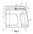
- FIG. 1is a right side elevational view of a paint container according to one embodiment of the present invention.
- FIG. 2is a rear elevational view of the FIG. 1 paint container.
- FIG. 3is a top plan view of the FIG. 1 paint container.
- FIG. 4is a left side elevational view, in full section, of the FIG. 1 paint container as viewed along line 4 — 4 in FIG. 2 .
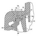
- FIG. 5is a partial, enlarged detail view, in full section, of the spout connection of the FIG. 1 paint container.
- FIG. 6is a right side elevational view of a paint container according to another embodiment of the present invention.
- FIG. 7is a rear elevational view of the FIG. 6 paint container.
- FIG. 8is a top plan view of the FIG. 6 paint container.
- FIG. 9is right side elevational view of a paint container according to another embodiment of the present invention.
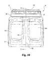
- FIG. 10is a rear elevational view of the FIG. 9 paint container.
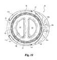
- FIG. 11is a top plan view of the FIG. 9 paint container.
- FIG. 12is a left side elevational view, in full section, of the FIG. 9 paint container as viewed along line 12 — 12 in FIG. 10 .
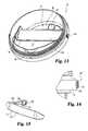
- FIG. 13is a perspective view of the spout of the FIG. 1 and FIG. 6 paint containers.
- FIG. 14is a partial, front elevational view of a pivot post comprising one portion of the FIG. 13 spout.
- FIG. 15is a partial perspective view of the handle of the FIG. 1 and FIG. 6 paint containers.
- FIG. 16is a partial, side elevational view, in full section, of a sealing mechanism for use with a container according to one embodiment of the present invention.
- FIG. 17is a partial, side elevational view, in full section, of a sealing mechanism for use with a container according to another embodiment of the present invention.
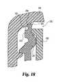
- FIG. 18is a partial, side elevational view, in full section, of a sealing mechanism for use with a container according to another embodiment of the present invention.
- FIG. 19is a partial, side elevational view, in full section, of a sealing mechanism for use with a container according to another embodiment of the present invention.
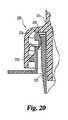
- FIG. 20is a partial, side elevational view, in full section, of a sealing mechanism for use with a container according to another embodiment of the present invention.
- FIG. 21is a partial, side elevational view, in full section, of a sealing mechanism for use with a container according to another embodiment of the present invention.
- FIG. 22is a partial, side elevational view, in full section, of a sealing mechanism for use with a container according to another embodiment of the present invention.
- FIG. 23is a partial, side elevational view, in full section, of a sealing mechanism for use with a container according to another embodiment of the present invention.
- FIG. 24is a partial, side elevational view, in full section, of a sealing mechanism for use with a container according to another embodiment of the present invention.
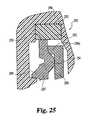
- FIG. 25is a partial, side elevational view, in full section, of a sealing mechanism for use with a container according to another embodiment of the present invention.
- the present inventionrelates to the design and construction of various sealing mechanisms and these are described in combination with various containers, preferably a molded plastic paint container with a pouring spout.
- FIGS. 1 , 2 , 3 , 4 , and 5there is illustrated a molded plastic paint container 20 according to a representative example for use with the preferred embodiments of the present invention.
- Paint container 20includes a contoured body 21 , pouring spout 22 , and threaded lid or cap 23 .
- a hinged, bail-like handle 24is attached to the pouring spout 22 .
- the spout 22includes a lower threaded portion 25 which threads onto the neck portion 26 of body 21 and an upper threaded portion 27 to which the cap 23 is threaded.
- FIGS. 6 , 7 , and 8illustrate a second configuration for the contoured body 30 of paint container 31 and a second configuration for the cooperating cap 32 .
- the spout and handle which are used in container 31are identical to spout 22 and handle 24 .
- the only difference between these first and second paint container designsresides in the shape and contouring of the container body and in the shape and contouring of the cooperating cap.
- FIGS. 9 , 10 , 11 , and 12a third configuration for the contoured body 35 of paint container 36 is illustrated. Included is a third configuration for the cooperating cap, though in many respects cap 37 is similar to cap 32 .
- the spout 22 ′ which is used in container 36is substantially identical to spout 22 . However, due to the molded-in handle 35 a as part of the contoured body 35 , a separate handle 24 , as might be hinged to the spout 22 , is not included. Accordingly, the spout of the FIGS. 9-12 embodiment has been referenced as 22 ′ to reflect the design change to omit the two pivot posts for handle 24 .
- FIGS. 13 and 14Additional details of spout 22 (and in part spout 22 ′) are illustrated in FIGS. 13 and 14 and these drawings should be referred to for a more complete understanding of the paint container 20 of FIGS. 1-5 . These spout details are also part of paint containers 31 and 36 . Similarly, additional details of the handle 24 and its connection to the pivot posts of spout 22 are illustrated in FIGS. 14 and 15 and these drawings should be referred to for a more complete understanding of the paint container 20 of FIGS. 1-5 . These handle details are also part of paint container 31 .
- paint container 20is a molded plastic container with a contoured body 21 sized to hold approximately, but at least, one gallon of paint within the defined interior volume.
- the contoured body 21includes a base 40 , sidewall 41 , and a series of external threads 42 on neck portion 26 which defines a circular opening 43 .
- the circular opening 43provides the means to initially fill the container 20 with paint. Thereafter, the spout 22 , handle 24 , and cap 23 are attached to securely close the circular opening 43 and thus securely close paint container 20 .
- the internally-threaded cap 23via threaded outer wall 23 a , will be threaded onto the upper threaded portion 27 of the spout and that the handle 24 will be attached to the spout, by means of two pivot posts 44 , before threading the spout to the neck portion 26 by way of threads 42 .
- the cap, spout, and handlecan be preassembled as a cap subassembly and attached as a single subassembly unit directly to the contoured body 21 as the lower threaded portion 25 of the spout 22 threads onto the neck portion 26 of the contoured body 21 .
- the preassembled subassembly of the cap 23 , spout 22 , and handle 24would not need to be removed from the contoured body 21 prior to first use. The purchaser/end user would then merely unscrew the cap 23 in order to gain access to the paint. However, if the initial fill of paint is a base color or tint which is going to be further colored or tinted by the addition of other pigment, then the store personnel would typically remove the preassembled subassembly of the cap 23 , spout 22 , and handle 24 in order to gain access to the paint in the body 21 in order to add the required pigment to create the selected color.
- the container body 21is closed by (re)attaching the spout 22 to the neck portion 26 , while the cap and handle remain assembled to the spout.
- the paint mixtureis then blended by a vibratory shaking process.
- One advantage of attaching the transporting handle 24 directly to an exterior wall surface of the spoutis to simplify the container body 21 design.
- the handle 24 in this locationdoes not interfere with the equipment for the vibratory shaking process. Also, by raising the handle pivot location to an upper location as compared to the body of the container, the balance of the container when dispensing paint is improved.
- the details of the present inventionare not size restrictive nor size limited. Whether considering the inventive features relating to the container structure or the inventive features relating to the various sealing mechanisms, the present invention details can be incorporated into virtually any size of container which can be used for virtually any type of product, most likely a liquid product.
- a one-gallon paint containerwas selected as the preferred embodiment to be used to describe the container structure and to describe the various sealing mechanisms disclosed herein and comprising part of the present invention. In this context, the purchaser/end user expects to receive at least one gallon of paint since that is how the package is marked and that is what is advertised.
- contoured body 21includes three recessed portions 46 a , 46 b , and 47 .
- the size, shape, and location of these three recessed portionsare important in view of their described functions.
- Portions 46 a and 46 bare best illustrated in FIG. 2 and are seen as being virtually identical to each other and symmetrically positioned on opposite sides of contoured body centerline 48 .
- the depth of each recessed portion 46 a and 46 bis approximately 1 ⁇ 2 inch at its deepest location, noting that there is a smooth and gradual transition by means of the rounded peripheral edges 49 a and 49 b which connect the interior of portions 46 a and 46 b , respectively, to the outer surface of sidewall 41 .
- each recessed portion 46 a and 46 bis adequate for the fingers on one side and the thumb on the other side of the end user to be placed on opposite sides of land portion 50 for gripping of the contoured body via land portion 50 , to assist in pouring paint from the body 21 by way of spout 22 .
- the symmetrical design and the virtually identical configuration of portions 46 a and 46 ballows the paint container to be used in an equally convenient manner by both right-handed and left-handed end users.
- centerline 48is the lateral centerline for handle 24 and for spout 22 , especially the pouring lip portion of spout 22 which will be described in greater detail later.
- the container 20can be lifted by the handle 24 by one hand and the body gripped by the other hand for tilting the body, with the cap 23 removed, in order to pour out paint by way of the pouring spout. Since the handle is attached to the spout as opposed to the container body, it moves the handle support line location closer to the pouring location and this yields better control and balance. If done correctly, the pouring paint is not able to contact any part of the handle and this lessens any spillage or mess.
- Recessed portion 47is continuous from one side of contoured body 21 to a corresponding location on the opposite side such that portion 47 is substantially symmetrical, in size, shape and location, relative to centerline 48 and effectively located opposite to portions 46 a and 46 b .
- the depth of portion 47is relatively shallow, approximately ⁇ fraction (1/16) ⁇ inch in depth, and is generally uniform throughout and is separated from the outer surface of sidewall 41 by a substantially flat, lateral peripheral edge 53 which surrounds and helps to define recessed portion 47 . This recessed portion 47 is used to receive a product label.
- the label thicknessis such that it fits within recessed portion 47 below the outer surface of sidewall 41 .
- the outer peripheral edge 53which surrounds the label protects and guards the peripheral edge of the label such that the label edge will not be caught or contacted in such a way that the label might either tear or begin to peel off from the container.
- the base 40is contoured with a recessed circular portion 55 which is sized, shaped, and positioned so as to be compatible with the size, shape and position of raised portion 56 of cap 23 .
- the raised portion 56is uniquely contoured for easier gripping of cap 23
- the outer peripheral shapeis part cylindrical and is capable of being inserted into a cylindrical recess, so long as the cylindrical recess is slightly larger and slightly deeper.
- the contoured body 21extends above the recessed portions 46 a , 46 b , and 47 into a curved portion 61 extending around the periphery of the upper part of the contoured body 21 .
- the curved portion 61then extends inwardly in a radial direction, at which point it joins neck portion 26 .
- the neck portion 26is annular with a substantially cylindrical inner surface 62 , terminating at top edge 63 which is substantially flat but which includes a slight unevenness and slight surface irregularities due to the molding process. Top edge 63 defines circular opening 43 .
- the exterior of the neck portion 26is externally threaded with threads 42 .
- the overall outer shape of body 21includes four sides for sidewall 41 and the rounded “corners” 64 a - 64 d between adjacent sides 65 a - 65 d .
- This top plan viewalso helps to illustrate the location of land portion 50 as well as the contoured and tapered sides of the land portion 50 which helps (ergonomically) with the comfort of the grip by the hand of the user.
- cap 23is recessed with an annular channel 68 which surrounds a gripping island 69 which is shaped with a series of three finger recesses 70 used to receive the first three fingers of the end user's hand for opening and closing the paint container by unscrewing (opening) the cap and by screwing the cap back in place in order to close the container.
- container 20is designed for paint and since this suggests the value of a large opening in the neck portion, i.e., circular opening 43 , the ergonomics of opening and closing the container by removing and reapplying the cap must be factored into the final design.
- cap 23is contoured with a smaller gripping portion in the form of gripping island 69 .
- land portion 50is provided and is able to be held with one hand when unscrewing the cap (and reapplying it) in order to hold the contoured body 21 relatively stationary. The other hand grasps gripping island 69 and uses finger recesses 70 to manipulate the cap 23 .
- the pouring spout 22includes an annular sidewall 73 which is slightly tapered in its lower portion, leading away from annular collar 74 in a downward axial direction toward lower edge 75 .
- the exterior surface of sidewall 73 above collar 74provides the upper threaded portion 27 .
- the outer annular wall 76depending from the radial wall 74 a of collar 74 , is internally threaded and provides the lower threaded portion 25 .
- the pouring spoutincludes an interior opening 77 , a wiping edge 78 , and a brush receptacle 79 which defines a series of apertures in bottom wall 80 for the drain-back of surplus paint into the interior volume 81 of the contoured body 21 .
- the pouring lip 82is positioned opposite to the brush receptacle 79 and extends in an upwardly direction as illustrated in FIG. 4 .
- Sealing of the interface between the spout 22 and neck portion 26can be provided by the interference fit between sidewall 73 and inner surface 62 , or at the interface between the radial wall 74 a of collar 74 and top edge 63 of the neck portion, or at both locations. While the achievement of suitable sealing can be attempted by merely surface-to-surface contact, the degree of tightness of the fit and the force required for tightly screwing the spout onto the neck, can be a consideration. To lessen the reliance on only the surface-to-surface contact between these two members, one or more sealing mechanisms can be incorporated into the design of paint container 20 .
- sealing structuresare disclosed in a more generic form relative to the two (or more) corresponding members which define the interface to be sealed. More specifically, the structural members which are disclosed generically represent any two (or more) structural members which have an interface where some degree of sealing is desired.
- one interface for sealingis between the spout and the contoured body.
- Another interface to be sealedis between the spout and the cap.
- paint container 20is generally symmetrical about centerline 48 and thus includes the associated component parts.
- the spout 22includes a pouring lip 82 which is centered on centerline 48 , while the handle 24 , land portion 50 , and recessed portion 49 are also entered in centerline 48 .
- the centerline alignment of the various portions and components of paint containers 20 , 31 , and 36is important for several reasons. From the standpoint of stacking and arranging the paint containers on a store shelf, it is preferable to have some uniformity as to the location or orientation of handle 24 and preferably to have it centered on the sides of the container so that the product label in the front is unobstructed.
- the threading of the spoutis also an important consideration as a way to properly orient the spout relative to the corresponding container body with a minimum of handling machinery complexity.
- the centerline of the pouring lip 82is preferably coincident with the centerline of handle 24 and with the centerline of land portion 50 or alternatively the molded-in handle 35 a . While the unitary construction of spout 22 (or spout 22 ′) can guarantee pouring lip 82 and handle 24 alignment, their centerline alignment to land portion 50 or handle 35 a depends on the position of the spout 22 within the container body 21 .
- a spoutis merely inserted into a container neck portion without any specific detents, indentations, keys, or some other indexing means to guarantee proper alignment
- the handling machinerywhich is used to deliver the various components to the installation location and the machinery used to actually install one component into the other must be arranged in some manner so as to either recognize and then orient the components in the proper alignment prior to assembly or deliver the components to the assembly location in the properly aligned orientation.
- the present inventionuses the threaded engagement between the spout 22 and neck portion 26 as well as the configuration of the threads on the neck portion and/or the configuration of the threads on the spout in order to guarantee the desired centerline alignment.
- the circumferential starting location for the threaded engagementcan be controlled based on the mold design for the container neck portion and/or based on the mold design for the spout.
- the thread pitch and thread lengthcan also be controlled and effectively these can be used to control the number of turns or revolutions of the spout 22 as it threads onto the neck portion 26 .
- a fixed position stopcan also be used as part of one or both sets of threads to precisely control where the threading of the spout onto the neck portion will stop.
- the container bodywill be provided in an upright orientation with the cap, spout, and handle removed. Paint is then added to the interior volume and the container body moves down the assembly line to the location where the cap, spout, and handle subassembly will be assembled.
- paint container 20 and the other two paint container embodiments disclosed hereinare not illustrated with any specific sealing mechanisms or structures, this was done to create a more generic container structure. It should be understood that one or more of those sealing mechanism embodiments disclosed herein can be used and preferably will be used as part of container 20 when container 20 is used for a liquid such as paint.
- the disclosed sealing mechanisms of the present inventioncan also be used as part of other container designs, even those that would not be directed to the storing and dispensing of paint.
- the structure of container 20 or either of the other two embodiments (containers 31 and 36 )can be used for storing and dispensing other product, such as fine granular material which is pourable. For such materials, no further sealing would be required beyond what is illustrated for the container embodiments of FIGS. 1-2 .
- the various sealing mechanisms of the present invention and how they can be adapted into paint container 20 , into the other two paint container embodiments, or into other container designswill be described herein.
- FIGS. 6 , 7 , and 8a second embodiment for a paint container 31 is illustrated.
- the same style of pouring spout 22 and handle 24are used in this embodiment (container 31 ) and their attachment or engagement with the cap 32 and neck portion 26 are the same as that illustrated as part of paint container 20 .
- the interior size and shape of the neck portion 26 of the FIGS. 6-8 container embodimentis substantially the same as the neck portion 26 of the FIGS. 1-5 container embodiment.
- the threaded engagementis the same and the surface-to-surface interference fit on the interior of the neck portion is the same.
- cap 32is different from the overall design of cap 23 , but the size, shape and arrangement of the interior of threaded outer wall 32 a of cap 32 is virtually identical to the size, shape and arrangement of the interior of threaded outer wall 23 a of cap 23 .
- the threaded engagement between the internal threads on the cap 32 and the upper threaded portion 27 on the spout 22is virtually the same in paint containers 20 and 31 .
- the differences between paint container 20 and paint container 31are found in the shaping and contouring of contoured body 30 and in the shaping and contouring of the exterior of cap 32 .
- contoured body 30it includes recessed portion 88 a , 88 b , and 89 .
- Portions 88 a and 88 bare similarly configured as hand gripping recesses on opposite sides of land portion 90 and are symmetrically arranged relative to centerline 91 .
- the peripheral edges 92 a and 92 b of each recessed portion 88 a and 88 bare smoothly contoured and curved as they extend from the base or bottom of each recessed portion upwardly and outwardly to outer surface 93 of contoured body 30 .
- Land portion 90which is centered in centerline 91 , is contoured and tapered along its (longitudinal) sides for easy gripping by the hand of the user. While the actual shapes of recessed portions 88 a , 88 b , and 89 are different from portions 46 a , 46 b , and 47 , they are intended to function and perform in virtually the same manner. This includes recessed portion 89 which is intended to receive a product label. The same is true for land portion 90 as compared to land portion 50 . While the corresponding shapes of these two land portions are slightly different, albeit in fairly minor ways, these two land portions 90 and 50 are intended to function and perform in virtually the same manner.
- cap 32With regard to cap 32 , it includes a generally cylindrical outer wall 32 a which defines a series of equally spaced, recessed pockets 95 which serve as finger indents to facilitate gripping of cap 32 by the hand of the user.
- the raised upper portion 96 of cap 32is generally cylindrical and cooperates with a recessed circular portion (not illustrated) in base 97 so as to enable to one (or more) paint containers 31 to be stacked by placing portion 96 of one container into portion 97 of another container.
- the upper surface of the raised upper portion 96is contoured with two recessed segment-shaped pockets 100 and 101 which are separated by dividing ridge 102 .
- the peripheral edges 103 of each pocket 101 , 102are smoothly contoured and curved as they extend from the bottom of each pocket to the outer surface of portion 96 .
- These two recessed pockets 100 and 101 in cooperation with the dividing ridge 102enable the cap 32 to be grasped in an ergonomically-convenient manner so as to more easily remove the cap 32 from the spout 22 in order to open container 31 and also to more easily reapply cap 32 to spout 22 to close container 31 .
- FIGS. 9 , 10 , 11 and 12a third embodiment for a paint container 36 is illustrated.
- container 36container 36
- its engagement with the cap 37 and with neck portion 26is basically the same as that illustrated for spout 22 as part of paint containers 20 and 31 .
- the one difference between spout 22 ′ and 22is the elimination of pivot posts 44 from spout 22 ′.
- a hinged, bail-like handleis not used and thus there is no need for the handle pivot posts 44 as part of the annular collar 106 .
- spout 22 ′could be replaced by spout 22 if such a handle might be desired as part of the overall container 36 design.
- Closing cap 37 of container 36is virtually identical to closing cap 32 of container 31 .
- the interior size and shape of the neck portion 26 of the FIGS. 9-12 paint container embodimentis substantially the same as the neck portion 26 of the FIGS. 1-5 and FIGS. 6-8 embodiments.
- the threaded engagement between the cap 37 and spout 22 ′is the same as in the prior two embodiments using spout 22 .
- the threaded engagement between the spout 22 ′ and container body 35is the same as in the prior two embodiments.
- the surface-to-surface interference fit on the interior between the neck portion 26 and spout inner sidewall 73is the same as in the prior two embodiments.
- cap 37is virtually identical to the design of cap 32 .
- the same recessed pockets 95are included as part of cap 37 as well as the two recessed segment-shaped pockets 100 and 101 and dividing ridge 102 .
- the contouring of the pockets 100 and 101is the same between cap 37 and cap 32 , including the same contoured peripheral edges 103 .
- Handle 35 ais centered on parting centerline 108 and is bounded on opposite sides by clearance spaces 109 a and 109 b . These clearance spaces help to provide hand clearance for the hand of the user to be able to reach around and fully grasp handle 35 a , allowing the fingers to extend into aperture 110 .
- the handle 35 a clearance spaces 109 a and 109 b and aperture 110are smoothly shaped and contoured for ergonomic comfort and convenience.
- the circumferential size of handle 35 ais ergonomically important, as is the contoured shape, including ridge 107 , in order to handle the weight and to dispense paint smoothly and in a controlled fashion.
- the single recessed portion of the prior two embodiments which is designed to receive a product labelhas been replaced with two recessed portions 111 a and 111 b located symmetrically on opposite sides of centerline 108 .
- the addition of handle 35 a and its configuration, as part of contoured body 35requires that for the most cost effective mold design, the mold parting line coincides with centerline 108 . With this parting line, any attempt to incorporate a molded-in label would not be possible with a single, wrap-around, recessed portion for the product label, as shown in the first two embodiments, noting portions 47 and 89 .
- this third embodiment for paint container 36discloses another feature of the present invention. Specifically, this embodiment discloses the concept and structure of two separate recessed portions for product labeling which portions are on opposite sides of the mold parting line such that molded-in-place labels can be used.
- the base 114 of contoured body 35is contoured with a recessed pocket 115 which is sized and shaped to receive the raised upper portion 116 of cap 37 for achieving the stackable capability for paint container 36 .
- the configuration of base 114 including pocket 115 and the configuration of upper portion 116are such that the stacking of paint container 36 can be achieved in basically the same manner as achieved for the first two paint container embodiments.
- FIGS. 14 and 15the details of handle 24 and its connection to spout 22 are illustrated.
- FIGS. 13 and 14illustrate the details of the pair of oppositely-disposed pivot posts 44 .
- each of the basic structural elements that are part of each paint container described herein, including paint containers 20 , 31 , and 36are molded out of plastic as unitary members. This means that each contoured body, each spout, each cap, and each separate handle, is a unitary, molded plastic member. It is intended that the selected materials will be recyclable materials.
- Suitable materials for the contoured bodyinclude various grades of polyethylene, ranging from medium to high-density resins.
- Suitable materials for the spout and capinclude a high-density, injection-molding grade, polyethylene resin.
- Suitable materials for the handleinclude a low to medium density polyethylene resin.
- each pivot post 44includes an enlarged cylindrical head 125 and a concentric, reduced diameter stem 126 integrally connecting the head 125 to the outer cylindrical surface of spout 22 .
- the cooperating handle 24includes a wider gripping portion 127 which connects to the oppositely-disposed, open sockets 128 by more narrow, tapered portions 129 .
- Each socket 128is substantially cylindrical with a pivot post entry opening 130 and a part-cylindrical groove 131 .
- the axial height or width of groove 131 in each socket 128is sized and arranged to receive the enlarged cylindrical head 125 of the corresponding pivot post 44 .
- the preferred approachis to do so with the spout separated from the remainder of the corresponding paint container.
- the handle 24is able to snap onto the two pivot posts 44 by first positioning the sockets above the posts such that each opening 130 is aligned with its corresponding pivot post 44 . Then, by pulling the handle down in the direction of the posts, the heads 125 are able to slide into the corresponding opening 130 and from there into the corresponding groove 131 .
- the handle bodyis then pivoted upwardly to a generally horizontal orientation. When the spout is attached to the container body, the handle is able to rest in this horizontal orientation by actually resting on a portion of the container body.
- the handleis able to freely pivot on pivot posts 44 from its horizontal, stowed condition to a vertical, dispensing condition.
- the handleIn order to separate handle 24 from the pivot posts 44 , the handle has to be moved so that the enlarged cylindrical head 125 of each pivot post can slide out of the receiving groove 131 .
- spout 22is illustrated. Included as part of spout 22 are a pouring lip 82 , a brush-wiping edge 78 , a brush-holding receptacle 79 , and drain-back apertures in bottom wall 80 .
- the pouring lip 82 and brush-wiping edge 78cooperate to define interior opening 77 .
- spout 22 ′is identical to spout 22 except for the elimination of pivot posts 44 from spout 22 ′.
- Spout 22has a substantially annular form for ease of insertion into neck portion 26 and for the described interference fit (around the entire circumference) due to the annular form of neck portion 26 .
- the interior opening 77is sized to receive a paint brush for dipping the brush into the paint contained within the interior volume 81 . As the paint brush is withdrawn, it can be rubbed across wiping edge 78 in order to wipe the excess paint from the brush bristles.
- the brush-wiping edge 78is actually part of blade 140 which is inclined with edge 78 being the lower point. Blade 140 is of a unitary construction with the inner surface of spout 22 and separates the interior opening 77 from the brush-holding receptacle 79 .
- the pouring lip 82includes a contoured center portion 82 a in order to help center the dispensing flow of paint and control the size and location of the existing stream of paint.
- Bottom wall 80is substantially flat and defines three drain-back apertures 141 . These apertures 141 allow any paint that drips or runs off of the paint brush when placed or stored in the receptacle 79 to return to the interior volume 81 of the container body. As the brush is wiped across edge 78 so as to remove excess paint, it is anticipated that some excess paint will actually collect on the surface of blade 140 .
- any excess paint that collects on the surface of blade 140is able to run down and back into the interior volume 81 by way of interior opening 77 . If the volume of paint being collected on blade 140 is such that some of the paint actually cascades over the opposite edge of blade 140 into receptacle 79 , this excess paint is also able to return to the interior volume 81 by way of drain-back apertures 141 .
- posts 44By locating posts 44 in a location which is axially close to pouring lip 82 and in particular portion 82 a , an improved balance for container 20 is achieved and this helps to smoothly dispense paint from container 20 by tilting and pouring.
- one or more sealing mechanisms or structureswill be arranged as part of paint containers 20 , 31 , and 36 . Since these sealing mechanisms according to the present invention have a broad application to other types of containers and for sealing an interface between two or more members, they are described in a more generic manner. In the context of the present invention, the locations within paint containers 20 , 31 , and 36 where one or more of the sealing mechanisms can be utilized are identified. Any minor details of exactly how to configure the two (or more) cooperating sealing portions of the two (or more) interface members in the context of the three paint container embodiments should be clear to one of ordinary skill in the art.
- FIGS. 16-25Continuing with the description of the various sealing structures or mechanisms of the present invention, reference will be made to FIGS. 16-25 .
- sealing mechanism 160which includes an annular container neck finish 161 fabricated from a mono block tool design with buttress threads 162 and squared, annular land area 163 at the upper surface.
- An integrated spout 164includes an outer radial projection 165 which rests on the inside edge of the land area 163 .
- the upper land portion 166 of the spoutis angled to allow minimal clearance between the spout outer surfaces of upper land portions 166 and 168 and the inside cap surfaces 169 and 170 , respectively.
- the cap 175includes an outer collar 176 with an angled portion 176 a which, when tightened onto a container (via surface 169 ), contacts the outer, upper edge 177 of the upper land area 163 with surface-to-surface interference. Sealing is achieved by deforming the upper edge 177 of land area 163 at an angle of between approximately 15 and 85 degrees. This may be accomplished either with a single angled surface or with a compound angled surface. As deformation continues to increase following multiple uses, the spout 164 is compressed onto the upper, annular land area 163 of the container, thereby providing additional sealing. The spout 164 also serves to provide structural support for the corresponding container by preventing collapse of the neck as the cap is tightened.
- the spoutis retained in the container by a small raised rib 178 , which may preferably be either solid or segmented, located on the outer surface 179 of wall 180 below the radial projection 165 .
- the combination of materials between cap 175 and container neck 161is such that one component has a lower modulus of elasticity relative to the other. This difference permits material deformation more readily of the component with the lower modulus in order to achieve sealing.
- sealing mechanism 190is illustrated.
- Sealing mechanism 190which includes cap 189 , spout 192 , and annular container neck 193 , is similar in certain respects to sealing mechanism 160 .
- One difference between these two designsrelates to the fact that the radial lip 191 of the spout 192 is located below the upper surface 196 of the container neck 193 and is retained by a raised rib 194 formed by a choker ring from the mono block tool design. Sealing is achieved by deforming the upper outer edge 195 at an angle of between approximately 15 and 85 degrees, either with a single angled surface as part of cap 189 or with a compound angled surface.
- Sealing mechanism 200which has similarity to sealing mechanism 190 .
- Sealing mechanism 200includes cap 189 , spout 192 , and annular container neck 201 .
- Container neck 201is designed with an annular undercut groove 202 formed into the outer surface 203 of the container neck finish 201 .
- the undercut groove 202forms a more conforming and flexible sealing lip 204 to the angled surface 205 of the cap 189 .
- This sealing mechanism 200would preferably require the spout 192 to be located below the upper surface of the container neck finish 201 .
- sealing mechanism 210which is similar to what is illustrated in FIG. 18 for sealing mechanism 200 .
- Sealing mechanism 210includes a cap 211 with an angled groove 212 therein which is provided to locate and form multiple sealing edges with container neck 214 . Sealing is achieved by wedging the upper lip portion 213 of the container neck 214 into a groove 212 which is located generally at the same diameter as that of container neck 214 .
- the groove 212is designed with angled side walls 215 and 216 , allowing optimal engagement and compression to the lip portion 213 of container neck 214 within the desired rotation and axial travel of caps 211 .
- the spout 217has a design which is substantially the same as spout 192 .
- sealing mechanism 220which includes closing cap 221 , annular container neck 222 , and spout 223 .
- Sealing mechanism 220further includes a flexible, annular lip 224 (or alternatively a plurality of annular lips) as part of cap 221 .
- the flexible lip 224is oriented in a slanting, inward direction and is constructed and arranged so as to sealingly contact the upper land surface 225 of the container neck 222 .
- the flexible lip 224is constructed and arranged to deform as the cap 221 is tightened onto the container neck, forming a concentrated sealing force applied onto the upper land surface 225 .
- sealing mechanism 230which includes closing cap 231 , annular container neck 232 , and spout 233 .
- the uniform container neck finish 232is formed from a mono block tool design with buttress threads 234 and squared, annular land area 235 at the upper surface.
- the integrated spout 233is constructed and arranged to cover the upper surface of land area 235 of the container neck 232 .
- Cap 231includes an inner angled surface 237 a on annular protrusion 237 which, when tightened onto a container, creates contact with the inner edge 236 of the spout. Sealing is achieved by means of short flat land seals 238 and 239 which make contact with the upper surface 240 of the spout 233 .
- the caphas an inner angled surface 237 a which deforms the inner edge 236 of the spout and container to form a complying sealing surface at that interface.
- Spout 233is preferably made from a material having a lower modulus of elasticity than that of annular protrusion 237 so as to bias sealing deflection into the spout. There are though cases when annular protrusion 237 is preferred to be biased and create sealing through deformation using a lower modulus material than that of spout 233 .
- sealing mechanism 244which includes closing cap 245 , annular container neck 246 , and spout 247 .
- Sealing mechanism 244which has a number of similarities to sealing mechanism 230 , further includes a flexible, annular member 248 which acts as a secondary seal and replaces the inner annular protrusion 237 .
- Container neck 246includes a uniform container neck finish fabricated from a mono block tool design with buttress threads 249 and squared land area 250 at the upper surface.
- Spout 247is constructed and arranged to cover the upper surface of the container neck.
- the flexible member 248protrudes downward from the deck of the cap which, when tightened onto a container, yields contact with the inner surface 251 of the spout.
- Sealingis achieved by means of short, flat land seals 252 and 253 which make contact with the upper surface 254 of the spout and from the flexible member 248 in contact with the spout.
- An additional, axially protruding, annular member 255is located radially inwardly of the flexible member 248 and extends axially below the flexible member 248 .
- This additional member 255provides protection (preventing damage) for the flexible member 248 during manufacturing, handling, and shipping and assembly. Means for preventing spout rotation may be employed with this sealing mechanism design.
- Member 255also provides a product baffle or shield that limits direct product influence when being shaken vigorously.
- sealing mechanism 260which includes closing cap 261 , annular container neck 262 , and spout 263 .
- the container neck 262 of sealing mechanism 260includes a uniform neck finish fabricated from a mono block tool design with buttress threads 264 and squared, land area 265 at the upper surface.
- the spout 263is constructed and arranged to cover the upper land area 265 of the container neck 262 .
- the cap 261extends over and around spout 263 and thus the outer radial collar 266 of the spout is sandwiched between the neck 262 and cap 261 .
- Sealingis achieved by means of tapered and projecting land seals 267 and 268 which are in the form of “V”-beads and which make contact with the land area 265 of the spout.
- the cap 261will also seal to the spout by means of flat, land seal 270 .
- the preferred embodimentis to have the “V”-beads 267 and 268 of a softer material so as to achieve deformation and provide sealing relative to container neck 262 .
- sealing mechanism 275which includes closing cap 276 , annular container neck 277 , and spout 278 .
- Sealing mechanism 275is similar to sealing mechanism 260 with the lone exception of including flexible member 279 protruding downwardly from the deck of cap 276 .
- Member 279is used to establish a sealed interface against the inner surface 280 of spout 278 .
- the capis tightened onto the neck 277 of the container, the size, shape and location of member 279 relative to the spout causes member 279 to deflect due to the interference which is experienced and this in turn creates a contact seal.
- sealing mechanism 285which includes closing cap 286 , annular container neck 287 , and spout 288 .
- the container neck 287includes a uniform bottle neck finish fabricated from a mono block tool design with buttress threads 289 and squared land area 280 at the upper surface.
- the spout 288includes a radial lip 288 a which is located below the upper surface 290 of the container neck and is retained by raised rib 291 formed by a choker ring from the mono block tool design.
- the upper inside surface of the capincludes (and defines) and annular groove 292 which receives a flexible, annular, square-cut gasket 293 .
- gasket 293 shapecould be round in lateral section or O-ring shaped. Sealing is achieved by means of compressing the gasket 293 against the upper surface 290 of the container neck in order to form a complying sealing surface at reduced torque amounts over other sealing means.
- the key to effective sealingis to select a gasket material which is compliant relative to sealing surface 290 .
- the sealing mechanisms disclosed as part of the present inventionare illustrated, in one general application, as they can be used for sealing an interface or interfaces between two or more structural members.
- the structural members selected as one means to describe the specifics of each sealing mechanisminclude a container body with a threaded neck portion, a pouring spout inserted into the neck portion, and a removable closing cap which is threadedly attachable to the container neck portion.
- one or more of the disclosed sealing mechanismscan also be used as part of other container configurations, including the paint container embodiments of FIGS. 1-15 , as one example of other compatible container configurations which are suitable to be configured with one or more of the disclosed sealing mechanisms.
- sealing mechanism 210 of FIG. 19As one example of how one or more of the sealing mechanisms disclosed herein can be adapted for use with one of the disclosed paint container embodiments, consider the sealing mechanism 210 of FIG. 19 . If we consider only the cap 211 and the container neck 214 , these two structural members have a wedge-type seal between lip portion 213 and groove 212 . This type of sealing mechanism could be used in paint container 20 by shaping cap 23 with groove 212 and spout 22 with lip portion 213 . In addition, or alternatively, this type of sealing mechanism could be used in paint container 20 by shaping spout 22 with groove 212 and the container neck portion 26 with lip portion 213 .
- the sealing mechanism 220 of FIG. 20can also be adapted for use with paint container 20 .
- one location for sealingis between the cap 23 and the upper edge (land area) of spout 22 .
- the cap 23needs to be shaped so as to include flexible lip 224 .
- another location for sealingis between the spout 22 and the top edge (land area) 63 of neck portion 26 .
- sealing mechanism 230 of FIG. 21can be adapted to be incorporated into paint container 20 at the location between the upper edge of the spout 22 and cap 23 .
- the improvement of sealing mechanism 244 of FIG. 22 in the form of protective member 255can be included as part of the modification of paint container 20 in order to incorporate this sealing mechanism.
Landscapes
- Engineering & Computer Science (AREA)
- Mechanical Engineering (AREA)
- Closures For Containers (AREA)
Abstract
Description
Claims (4)
Priority Applications (8)
| Application Number | Priority Date | Filing Date | Title |
|---|---|---|---|
| US10/199,618US6843389B2 (en) | 2002-07-19 | 2002-07-19 | Sealing mechanisms for use in liquid-storage containers |
| US10/365,910US6997354B2 (en) | 2002-07-19 | 2003-02-13 | Sealing mechanisms for use in liquid-storage containers |
| PCT/US2003/019247WO2004010038A2 (en) | 2002-07-19 | 2003-06-18 | Sealing mechanisms for use in liquid-storage containers |
| EP03742059AEP1579139A4 (en) | 2002-07-19 | 2003-06-18 | Sealing mechanisms for use in liquid-storage containers |
| MXPA05000769AMXPA05000769A (en) | 2002-07-19 | 2003-06-18 | Sealing mechanisms for use in liquid-storage containers. |
| AU2003281599AAU2003281599A1 (en) | 2002-07-19 | 2003-06-18 | Sealing mechanisms for use in liquid-storage containers |
| US10/924,419US7216779B2 (en) | 2002-07-19 | 2004-08-24 | Sealing mechanisms for use in liquid-storage containers |
| US11/353,929US7677423B2 (en) | 2002-07-19 | 2006-02-14 | Sealing mechanisms for use in liquid-storage containers |
Applications Claiming Priority (1)
| Application Number | Priority Date | Filing Date | Title |
|---|---|---|---|
| US10/199,618US6843389B2 (en) | 2002-07-19 | 2002-07-19 | Sealing mechanisms for use in liquid-storage containers |
Related Child Applications (2)
| Application Number | Title | Priority Date | Filing Date |
|---|---|---|---|
| US10/365,910Continuation-In-PartUS6997354B2 (en) | 2002-07-19 | 2003-02-13 | Sealing mechanisms for use in liquid-storage containers |
| US10/924,419ContinuationUS7216779B2 (en) | 2002-07-19 | 2004-08-24 | Sealing mechanisms for use in liquid-storage containers |
Publications (2)
| Publication Number | Publication Date |
|---|---|
| US20040011812A1 US20040011812A1 (en) | 2004-01-22 |
| US6843389B2true US6843389B2 (en) | 2005-01-18 |
Family
ID=30443350
Family Applications (2)
| Application Number | Title | Priority Date | Filing Date |
|---|---|---|---|
| US10/199,618Expired - LifetimeUS6843389B2 (en) | 2002-07-19 | 2002-07-19 | Sealing mechanisms for use in liquid-storage containers |
| US10/924,419Expired - LifetimeUS7216779B2 (en) | 2002-07-19 | 2004-08-24 | Sealing mechanisms for use in liquid-storage containers |
Family Applications After (1)
| Application Number | Title | Priority Date | Filing Date |
|---|---|---|---|
| US10/924,419Expired - LifetimeUS7216779B2 (en) | 2002-07-19 | 2004-08-24 | Sealing mechanisms for use in liquid-storage containers |
Country Status (1)
| Country | Link |
|---|---|
| US (2) | US6843389B2 (en) |
Cited By (15)
| Publication number | Priority date | Publication date | Assignee | Title |
|---|---|---|---|---|
| US20040026450A1 (en)* | 2002-04-19 | 2004-02-12 | Rohr Robert D. | Container for holding a product |
| US20050023293A1 (en)* | 2002-07-19 | 2005-02-03 | Kasting Thomas P. | Sealing mechanisms for use in liquid-storage containers |
| US20050189355A1 (en)* | 2004-03-01 | 2005-09-01 | Masterchem Industries, Inc. | Container cap |
| US20050230440A1 (en)* | 2004-03-01 | 2005-10-20 | Masterchem Industries Llc | Container sealing system |
| US20050247728A1 (en)* | 2002-07-19 | 2005-11-10 | Rieke Corporation | Container for liquids, including sealing mechanisms |
| US20060201977A1 (en)* | 2002-07-19 | 2006-09-14 | Rieke Corporation | Sealing mechanisms for use in liquid-storage containers |
| US20060207963A1 (en)* | 2004-11-18 | 2006-09-21 | Plastipak Packaging, Inc. | Plastic container |
| US20070108084A1 (en)* | 2005-11-17 | 2007-05-17 | Randall Susan M | Paint storage and touch-up container |
| US20080128380A1 (en)* | 2006-11-07 | 2008-06-05 | Denner John E | Plastic container and closure and system and method of making the same |
| US20080141454A1 (en)* | 2006-11-03 | 2008-06-19 | Joel Blomet | Individual portable device for eye bath |
| US20110095058A1 (en)* | 2009-07-31 | 2011-04-28 | Colgate-Palmolive Company | Closure for a container |
| US20120280062A1 (en)* | 2011-05-06 | 2012-11-08 | Saint-Gobain Abrasifs | Multi-seal paint cup assembly |
| US20130276413A1 (en)* | 2010-12-23 | 2013-10-24 | Manfred Imand Kurmis | Sealing assembly for a closure |
| US8757453B1 (en)* | 2007-01-10 | 2014-06-24 | Sven O. Olsson | Pouring spout |
| US8777033B2 (en) | 2010-10-29 | 2014-07-15 | Graham Packaging Company, L.P. | Plastic container with reinforced base and closure and system and method of making same |
Families Citing this family (19)
| Publication number | Priority date | Publication date | Assignee | Title |
|---|---|---|---|---|
| US7353973B2 (en)* | 2004-11-15 | 2008-04-08 | Rieke Corporation | Seal retainer for use in liquid-storage containers |
| US20070278256A1 (en)* | 2006-06-06 | 2007-12-06 | Law Brian R | Tamper-evident closure for a container |
| US7644829B2 (en)* | 2006-08-07 | 2010-01-12 | Plastipak Packaging, Inc. | Plastic container including a grip feature |
| US7891512B2 (en)* | 2006-12-06 | 2011-02-22 | Reckitt Benckiser Inc. | Linerless closure for a container |
| GB2448579A (en)* | 2007-04-17 | 2008-10-22 | Ici Plc | Painting apparatus with a paint supply dip-tube assembly |
| GB0707352D0 (en)* | 2007-04-17 | 2007-05-23 | Ici Plc | A Painting system |
| DE102009011178A1 (en)* | 2009-03-04 | 2010-09-16 | Henkel Ag & Co. Kgaa | repairing |
| US20110132941A1 (en)* | 2009-12-08 | 2011-06-09 | Kim Sang Soon | Spout for a pouch |
| US8490817B2 (en) | 2010-05-21 | 2013-07-23 | Lee Hamminga | Container sealing device |
| USD673370S1 (en) | 2011-08-24 | 2013-01-01 | Wilmar Corporation | Open-ended container system |
| USD669273S1 (en)* | 2011-08-24 | 2012-10-23 | Wilmar Corporation | Open-ended container |
| USD672559S1 (en) | 2011-08-24 | 2012-12-18 | Wilmar Corporation | Open-ended container |
| US10005214B1 (en) | 2014-07-03 | 2018-06-26 | Plastek Industries, Inc. | Cap manufacture methods and apparatus |
| CA3018336C (en)* | 2016-03-21 | 2020-09-22 | The Sherwin-Williams Company | Storage container with spout |
| US10167118B1 (en) | 2016-04-28 | 2019-01-01 | Plastek Industries, Inc. | Closure cap with a flange upper surface having an interrupted annular recess |
| USD873667S1 (en)* | 2017-07-10 | 2020-01-28 | The Sherwin-Williams Company | Storage container |
| US10167115B1 (en) | 2017-12-29 | 2019-01-01 | Buddeez, Inc. | Sealable container assembly with internal, removable panel and spout |
| CN108341162A (en)* | 2018-01-29 | 2018-07-31 | 广东汇伟塑胶股份有限公司 | A kind of packaging cup |
| US11673719B2 (en)* | 2020-08-04 | 2023-06-13 | Silgan Dispensing Systems Slatersville, Llc | Two-piece drop dispensing closure |
Citations (47)
| Publication number | Priority date | Publication date | Assignee | Title |
|---|---|---|---|---|
| US1632848A (en) | 1926-09-15 | 1927-06-21 | Continental Can Co | Sheet-metal container |
| US1694165A (en) | 1927-10-14 | 1928-12-04 | Robert R Debacher | Bail for pails and the like |
| US3074579A (en)* | 1960-01-15 | 1963-01-22 | Formold Plastics Inc | Combination closure cap and stopper |
| US3275366A (en) | 1965-02-23 | 1966-09-27 | Walter E Hidding | Plastic carrier for bottles |
| US3856200A (en) | 1971-05-13 | 1974-12-24 | Maschf Augsburg Nuernberg Ag | Damping device for rapidly spinning rotary body |
| US4245753A (en) | 1979-10-04 | 1981-01-20 | Ellis Henry D | Container for paint |
| US4399926A (en) | 1982-04-29 | 1983-08-23 | Eidels Dubovoy Samuel | Resealable easy-opening container |
| US4453647A (en) | 1983-01-26 | 1984-06-12 | Neat Benjamin C | Plastic container having threaded closure |
| US4550862A (en) | 1982-11-17 | 1985-11-05 | The Procter & Gamble Company | Liquid product pouring and measuring package with self draining feature |
| US4619373A (en) | 1985-10-04 | 1986-10-28 | Galer Herbert W | Plastic paint container |
| US4671421A (en) | 1986-03-06 | 1987-06-09 | Owens-Illinois, Inc. | Plastic container |
| US4673625A (en) | 1986-08-04 | 1987-06-16 | General Motors Corporation | Battery and handle therefor |
| US4706829A (en) | 1986-02-07 | 1987-11-17 | Owens-Illinois Closure Inc. | Liquid containing and dispensing package |
| US4736874A (en) | 1986-11-24 | 1988-04-12 | Durant Will G | Apparatus for use on open-mouth cans for pouring liquid therefrom |
| US4836419A (en)* | 1988-05-02 | 1989-06-06 | Jennico, Inc. | Closure mechanism for liquid containers |
| US4856673A (en) | 1988-06-27 | 1989-08-15 | Sterling Drug Inc. | Container convertible to a child's pail |
| US4917270A (en)* | 1987-06-29 | 1990-04-17 | Societe De Conseils Et D'etudes Des Emballages S.C.E.E. | Closure device with pouring nozzle and pouring spout metering stopper |
| US4974749A (en) | 1988-11-16 | 1990-12-04 | Colgate-Palmolive Co. | Dripless measuring cup for closure assembly |
| US4984714A (en) | 1990-01-09 | 1991-01-15 | Specialty Packaging Licensing Company | Spouted bottle |
| US4993605A (en) | 1988-11-16 | 1991-02-19 | Colgate-Palmolive Company | Closure assembly with pouring spout and measuring cup |
| US5058772A (en) | 1989-11-13 | 1991-10-22 | Phoenix Closures, Inc. | Dispenser closure with drain back feature |
| US5101993A (en)* | 1990-05-10 | 1992-04-07 | Phoenix Closures, Inc. | Closure seal |
| US5108009A (en) | 1986-02-12 | 1992-04-28 | Lever Brothers Company, Division Of Conopco, Inc. | Leak and drip resistant storage dispensing and measuring package |
| US5188249A (en) | 1991-09-11 | 1993-02-23 | Graham Packaging Corporation | Plastic bottle having a linerless closure with collapsible flange and method |
| US5228596A (en) | 1991-06-19 | 1993-07-20 | The Procter & Gamble Company | Outwardly projecting directed pour spout exhibiting thread compatible cross-sectional profile |
| US5234130A (en) | 1991-03-22 | 1993-08-10 | Manhattan Products, Inc. | Dispensing package for a pourable material having a bottle, a pour-back spout and a closure |
| US5251788A (en)* | 1992-04-23 | 1993-10-12 | Phoenix Closures, Inc. | Pour spout and dispenser closure with drainage feature |
| US5269438A (en) | 1989-03-21 | 1993-12-14 | Crown Berger Europe Limited | Container for liquids |
| US5344041A (en) | 1993-09-14 | 1994-09-06 | Ropak Corporation | Bail for container and attachment means therefor |
| US5431306A (en) | 1993-12-31 | 1995-07-11 | Innovative Molding, Inc. | Drain back container with internal thread |
| US5435467A (en) | 1994-04-20 | 1995-07-25 | Phoenix Closures, Inc. | Stackable dispenser closure |
| US5457850A (en) | 1992-07-10 | 1995-10-17 | Cardinal Packaging, Inc. | Plastic bail handle |
| US5462202A (en) | 1994-08-25 | 1995-10-31 | Owens-Illinois Closure Inc. | Liquid containing and dispensing package |
| US5472121A (en) | 1994-03-04 | 1995-12-05 | Silano; John R. | Plastic lid with pour spout, vent and snap on cap |
| US5566862A (en) | 1994-10-24 | 1996-10-22 | Owens-Illinois Closure Inc. | Liquid containing and dispensing package |
| US5597090A (en) | 1994-11-25 | 1997-01-28 | Leahy; David J. | Controlled pourability of fluids |
| US5624772A (en) | 1995-11-17 | 1997-04-29 | General Motors Corporation | Battery handle |
| US5669526A (en) | 1996-03-28 | 1997-09-23 | Keyfauver; Terry L. | Stackable spill proof paint can |
| US5816439A (en) | 1995-02-17 | 1998-10-06 | Industrial Containers Ltd. | Container with handle |
| US5855304A (en) | 1995-02-03 | 1999-01-05 | Dean; Richard A. | Paint can |
| US5941422A (en) | 1998-04-06 | 1999-08-24 | Owens-Brockway Plastic Products Inc. | Liquid containing and dispensing package |
| US6126048A (en) | 1999-06-24 | 2000-10-03 | Bublitz; Todd F. | Removable paint can extension and cover |
| US6209762B1 (en) | 1998-01-29 | 2001-04-03 | Owens-Illinois Closure Inc. | Dispensing package and method of use |
| US6257440B1 (en) | 1999-04-08 | 2001-07-10 | Ropak Corporation | Container handle and related methods |
| US6269949B1 (en) | 2000-05-10 | 2001-08-07 | Ron Gottlieb | Stackable beverage container with rotatable handle |
| US6269977B1 (en) | 2000-01-26 | 2001-08-07 | Kim Ira Moore | Stackable container cover |
| US20010025865A1 (en) | 1999-07-08 | 2001-10-04 | Michael H. Bravo | Improved storage and dispensing container for viscous fluids paints and the like and method of minimizing dripping |
Family Cites Families (26)
| Publication number | Priority date | Publication date | Assignee | Title |
|---|---|---|---|---|
| US195471A (en)* | 1877-09-25 | Improvement in water-proof cellar-bottoms | ||
| US25865A (en)* | 1859-10-18 | Improvement in bustles | ||
| US2763403A (en)* | 1953-06-16 | 1956-09-18 | Jay G Livingstone | Fittings |
| US3208650A (en)* | 1963-12-30 | 1965-09-28 | Anfinsen Plastic Molding Inc | Combined flexible closure and pouring spout |
| US3339772A (en)* | 1964-11-16 | 1967-09-05 | Formold Plastics Inc | Container cap |
| US3491924A (en)* | 1968-01-08 | 1970-01-27 | Bloomfield Ind Inc | Pouring spouts for decanters |
| US3586200A (en) | 1968-11-01 | 1971-06-22 | Life Like Products Inc | Carrying handle |
| US4034901A (en)* | 1975-04-18 | 1977-07-12 | Norman Kirk | Dripless spout for paint cans |
| FR2381678A1 (en)* | 1977-02-28 | 1978-09-22 | Rical Sa | PERFECTED CAP FOR THE DISPENSER OR DISPENSER OPERCULE FOR BOTTLES OR SIMILAR CONTAINERS |
| US4353489A (en)* | 1980-09-22 | 1982-10-12 | Arnold Everett L | Combined lid and pouring spout for a container having a U-shaped sealing channel |
| US4387819A (en)* | 1981-12-23 | 1983-06-14 | Corsette Douglas Frank | Sealing means for a snap-on fitment |
| US4433800A (en)* | 1981-12-24 | 1984-02-28 | Top-Seal Corporation | Pouring fitment and closure assembly |
| DE3416817A1 (en)* | 1984-05-07 | 1985-11-07 | Varta Batterie Ag, 3000 Hannover | METHOD FOR PRODUCING A GAS-TIGHTLY SEALED ALKALINE ACCUMULATOR |
| FR2617133B1 (en)* | 1987-06-25 | 1990-01-26 | Astra Plastique | METERING CAP FOR CONTAINER WITH THREADED NECK AND SIDE HANDLE |
| US4917268A (en)* | 1988-06-20 | 1990-04-17 | The Clorox Company | Liquid dispensing package with drainback spout |
| US4893723A (en)* | 1988-06-28 | 1990-01-16 | Seabolt John K | Paint can attachment |
| US5234133A (en)* | 1991-10-31 | 1993-08-10 | Kensey Lenard M | Container pouring attachment with replaceable pouring structures |
| FI92043C (en)* | 1992-09-18 | 1994-09-26 | Kone Oy | Elevator rope arrangement |
| US5289950A (en)* | 1992-09-30 | 1994-03-01 | Chesebrough-Pond's Usa Co., Division Of Conopco, Inc. | Multiple chamber dispensing package with closure system |
| US5868283A (en)* | 1996-07-02 | 1999-02-09 | Lever Brothers Company, Division Of Conopco, Inc. | Reclosable closure and bottle |
| DE29802048U1 (en) | 1998-02-09 | 1998-04-02 | Jokey Plastik Wipperfürth GmbH, 51688 Wipperfürth | Paint can |
| US6059153A (en)* | 1998-10-09 | 2000-05-09 | Kraft Foods, Inc. | Container for pourable food products |
| MXPA03009605A (en)* | 2001-04-18 | 2004-05-05 | Nottingham Spirk Partners Llc | Improved container and lid assembly. |
| US7036693B2 (en)* | 2001-12-05 | 2006-05-02 | Masterchem Industries Llc | Paint container |
| US6843389B2 (en)* | 2002-07-19 | 2005-01-18 | Rieke Corporation | Sealing mechanisms for use in liquid-storage containers |
| EP1601894A4 (en)* | 2003-02-28 | 2016-03-09 | Chesterton A W Co | Balanced mechanical seal assembly |
- 2002
- 2002-07-19USUS10/199,618patent/US6843389B2/ennot_activeExpired - Lifetime
- 2004
- 2004-08-24USUS10/924,419patent/US7216779B2/ennot_activeExpired - Lifetime
Patent Citations (48)
| Publication number | Priority date | Publication date | Assignee | Title |
|---|---|---|---|---|
| US1632848A (en) | 1926-09-15 | 1927-06-21 | Continental Can Co | Sheet-metal container |
| US1694165A (en) | 1927-10-14 | 1928-12-04 | Robert R Debacher | Bail for pails and the like |
| US3074579A (en)* | 1960-01-15 | 1963-01-22 | Formold Plastics Inc | Combination closure cap and stopper |
| US3275366A (en) | 1965-02-23 | 1966-09-27 | Walter E Hidding | Plastic carrier for bottles |
| US3856200A (en) | 1971-05-13 | 1974-12-24 | Maschf Augsburg Nuernberg Ag | Damping device for rapidly spinning rotary body |
| US4245753A (en) | 1979-10-04 | 1981-01-20 | Ellis Henry D | Container for paint |
| US4399926A (en) | 1982-04-29 | 1983-08-23 | Eidels Dubovoy Samuel | Resealable easy-opening container |
| US4550862A (en) | 1982-11-17 | 1985-11-05 | The Procter & Gamble Company | Liquid product pouring and measuring package with self draining feature |
| US4453647A (en) | 1983-01-26 | 1984-06-12 | Neat Benjamin C | Plastic container having threaded closure |
| US4619373A (en) | 1985-10-04 | 1986-10-28 | Galer Herbert W | Plastic paint container |
| US4706829A (en) | 1986-02-07 | 1987-11-17 | Owens-Illinois Closure Inc. | Liquid containing and dispensing package |
| US5108009A (en) | 1986-02-12 | 1992-04-28 | Lever Brothers Company, Division Of Conopco, Inc. | Leak and drip resistant storage dispensing and measuring package |
| US4671421A (en) | 1986-03-06 | 1987-06-09 | Owens-Illinois, Inc. | Plastic container |
| US4673625A (en) | 1986-08-04 | 1987-06-16 | General Motors Corporation | Battery and handle therefor |
| US4736874A (en) | 1986-11-24 | 1988-04-12 | Durant Will G | Apparatus for use on open-mouth cans for pouring liquid therefrom |
| US4917270A (en)* | 1987-06-29 | 1990-04-17 | Societe De Conseils Et D'etudes Des Emballages S.C.E.E. | Closure device with pouring nozzle and pouring spout metering stopper |
| US4836419A (en)* | 1988-05-02 | 1989-06-06 | Jennico, Inc. | Closure mechanism for liquid containers |
| US4856673A (en) | 1988-06-27 | 1989-08-15 | Sterling Drug Inc. | Container convertible to a child's pail |
| US4974749A (en) | 1988-11-16 | 1990-12-04 | Colgate-Palmolive Co. | Dripless measuring cup for closure assembly |
| US4993605A (en) | 1988-11-16 | 1991-02-19 | Colgate-Palmolive Company | Closure assembly with pouring spout and measuring cup |
| US5269438A (en) | 1989-03-21 | 1993-12-14 | Crown Berger Europe Limited | Container for liquids |
| US5058772A (en) | 1989-11-13 | 1991-10-22 | Phoenix Closures, Inc. | Dispenser closure with drain back feature |
| US4984714A (en) | 1990-01-09 | 1991-01-15 | Specialty Packaging Licensing Company | Spouted bottle |
| US5101993A (en)* | 1990-05-10 | 1992-04-07 | Phoenix Closures, Inc. | Closure seal |
| US5234130A (en) | 1991-03-22 | 1993-08-10 | Manhattan Products, Inc. | Dispensing package for a pourable material having a bottle, a pour-back spout and a closure |
| US5228596A (en) | 1991-06-19 | 1993-07-20 | The Procter & Gamble Company | Outwardly projecting directed pour spout exhibiting thread compatible cross-sectional profile |
| US5188249A (en) | 1991-09-11 | 1993-02-23 | Graham Packaging Corporation | Plastic bottle having a linerless closure with collapsible flange and method |
| US5251788A (en)* | 1992-04-23 | 1993-10-12 | Phoenix Closures, Inc. | Pour spout and dispenser closure with drainage feature |
| US5457850A (en) | 1992-07-10 | 1995-10-17 | Cardinal Packaging, Inc. | Plastic bail handle |
| US5344041A (en) | 1993-09-14 | 1994-09-06 | Ropak Corporation | Bail for container and attachment means therefor |
| US5603787A (en) | 1993-12-31 | 1997-02-18 | Innovative Molding, Inc. | Drain back container assembly |
| US5431306A (en) | 1993-12-31 | 1995-07-11 | Innovative Molding, Inc. | Drain back container with internal thread |
| US5472121A (en) | 1994-03-04 | 1995-12-05 | Silano; John R. | Plastic lid with pour spout, vent and snap on cap |
| US5435467A (en) | 1994-04-20 | 1995-07-25 | Phoenix Closures, Inc. | Stackable dispenser closure |
| US5462202A (en) | 1994-08-25 | 1995-10-31 | Owens-Illinois Closure Inc. | Liquid containing and dispensing package |
| US5566862A (en) | 1994-10-24 | 1996-10-22 | Owens-Illinois Closure Inc. | Liquid containing and dispensing package |
| US5597090A (en) | 1994-11-25 | 1997-01-28 | Leahy; David J. | Controlled pourability of fluids |
| US5855304A (en) | 1995-02-03 | 1999-01-05 | Dean; Richard A. | Paint can |
| US5816439A (en) | 1995-02-17 | 1998-10-06 | Industrial Containers Ltd. | Container with handle |
| US5624772A (en) | 1995-11-17 | 1997-04-29 | General Motors Corporation | Battery handle |
| US5669526A (en) | 1996-03-28 | 1997-09-23 | Keyfauver; Terry L. | Stackable spill proof paint can |
| US6209762B1 (en) | 1998-01-29 | 2001-04-03 | Owens-Illinois Closure Inc. | Dispensing package and method of use |
| US5941422A (en) | 1998-04-06 | 1999-08-24 | Owens-Brockway Plastic Products Inc. | Liquid containing and dispensing package |
| US6257440B1 (en) | 1999-04-08 | 2001-07-10 | Ropak Corporation | Container handle and related methods |
| US6126048A (en) | 1999-06-24 | 2000-10-03 | Bublitz; Todd F. | Removable paint can extension and cover |
| US20010025865A1 (en) | 1999-07-08 | 2001-10-04 | Michael H. Bravo | Improved storage and dispensing container for viscous fluids paints and the like and method of minimizing dripping |
| US6269977B1 (en) | 2000-01-26 | 2001-08-07 | Kim Ira Moore | Stackable container cover |
| US6269949B1 (en) | 2000-05-10 | 2001-08-07 | Ron Gottlieb | Stackable beverage container with rotatable handle |
Cited By (25)
| Publication number | Priority date | Publication date | Assignee | Title |
|---|---|---|---|---|
| US20040026450A1 (en)* | 2002-04-19 | 2004-02-12 | Rohr Robert D. | Container for holding a product |
| US20060289570A1 (en)* | 2002-04-19 | 2006-12-28 | Rohr Robert D | Container for holding a product |
| US7175051B2 (en)* | 2002-07-19 | 2007-02-13 | Rieke Corporation | Container for liquids, including sealing mechanisms |
| US20050023293A1 (en)* | 2002-07-19 | 2005-02-03 | Kasting Thomas P. | Sealing mechanisms for use in liquid-storage containers |
| US7677423B2 (en) | 2002-07-19 | 2010-03-16 | Rieke Corporation | Sealing mechanisms for use in liquid-storage containers |
| US20050247728A1 (en)* | 2002-07-19 | 2005-11-10 | Rieke Corporation | Container for liquids, including sealing mechanisms |
| US20060201977A1 (en)* | 2002-07-19 | 2006-09-14 | Rieke Corporation | Sealing mechanisms for use in liquid-storage containers |
| US7216779B2 (en) | 2002-07-19 | 2007-05-15 | Rieke Corporation | Sealing mechanisms for use in liquid-storage containers |
| US20050230440A1 (en)* | 2004-03-01 | 2005-10-20 | Masterchem Industries Llc | Container sealing system |
| US20050189355A1 (en)* | 2004-03-01 | 2005-09-01 | Masterchem Industries, Inc. | Container cap |
| US7520410B2 (en)* | 2004-03-01 | 2009-04-21 | Masterchem Industries, Llc | Container sealing system |
| US20060207963A1 (en)* | 2004-11-18 | 2006-09-21 | Plastipak Packaging, Inc. | Plastic container |
| US8025176B2 (en)* | 2004-11-18 | 2011-09-27 | Plastipak Packaging, Inc. | Plastic container including a grip feature |
| US20070108084A1 (en)* | 2005-11-17 | 2007-05-17 | Randall Susan M | Paint storage and touch-up container |
| US20080141454A1 (en)* | 2006-11-03 | 2008-06-19 | Joel Blomet | Individual portable device for eye bath |
| US8845602B2 (en)* | 2006-11-03 | 2014-09-30 | Prevor International | Individual portable device for eye bath |
| US7988002B2 (en) | 2006-11-07 | 2011-08-02 | Graham Packaging Company, L.P. | Plastic container and closure and system and method of making the same |
| US20080128380A1 (en)* | 2006-11-07 | 2008-06-05 | Denner John E | Plastic container and closure and system and method of making the same |
| US8757453B1 (en)* | 2007-01-10 | 2014-06-24 | Sven O. Olsson | Pouring spout |
| US20110095058A1 (en)* | 2009-07-31 | 2011-04-28 | Colgate-Palmolive Company | Closure for a container |
| US8534510B2 (en) | 2009-07-31 | 2013-09-17 | Colgate-Palmolive Company | Closure for a container |
| US8777033B2 (en) | 2010-10-29 | 2014-07-15 | Graham Packaging Company, L.P. | Plastic container with reinforced base and closure and system and method of making same |
| US20130276413A1 (en)* | 2010-12-23 | 2013-10-24 | Manfred Imand Kurmis | Sealing assembly for a closure |
| US9981781B2 (en)* | 2010-12-23 | 2018-05-29 | Manfred Imand Kurmis | Sealing assembly for a closure |
| US20120280062A1 (en)* | 2011-05-06 | 2012-11-08 | Saint-Gobain Abrasifs | Multi-seal paint cup assembly |
Also Published As
| Publication number | Publication date |
|---|---|
| US7216779B2 (en) | 2007-05-15 |
| US20050023293A1 (en) | 2005-02-03 |
| US20040011812A1 (en) | 2004-01-22 |
Similar Documents
| Publication | Publication Date | Title |
|---|---|---|
| US6843389B2 (en) | Sealing mechanisms for use in liquid-storage containers | |
| US7040509B2 (en) | Container for liquids, including sealing mechanisms | |
| US7677423B2 (en) | Sealing mechanisms for use in liquid-storage containers | |
| US7347343B2 (en) | Container for liquids, including sealing mechanisms | |
| US6530500B2 (en) | Storage and dispensing container for viscous fluids, paints and the like, and method of minimizing dripping | |
| US20090159607A1 (en) | Pouring and sealing attachment | |
| US5947319A (en) | Paint can lid with wire handle engagement | |
| EP0175687A1 (en) | Plastic container | |
| CA2543599C (en) | Container sealing system | |
| US8215506B2 (en) | Flip top closure assembly for a bottle | |
| US7520410B2 (en) | Container sealing system | |
| AU2003238560B2 (en) | A pouring and sealing attachment | |
| EP0654417A1 (en) | Refillable package | |
| US20050145655A1 (en) | Flip-top closure |
Legal Events
| Date | Code | Title | Description |
|---|---|---|---|
| AS | Assignment | Owner name:RIEKE CORPORATION, INDIANA Free format text:ASSIGNMENT OF ASSIGNORS INTEREST;ASSIGNORS:KASTING, THOMAS P.;WITTE, JAY E.;ROHR, ROBERT D.;REEL/FRAME:013244/0550 Effective date:20020730 | |
| STCF | Information on status: patent grant | Free format text:PATENTED CASE | |
| CC | Certificate of correction | ||
| FPAY | Fee payment | Year of fee payment:4 | |
| AS | Assignment | Owner name:THE BANK OF NEW YORK MELLON TRUST COMPANY, N.A., A Free format text:SECURITY AGREEMENT;ASSIGNORS:TRIMAS CORPORATION;TRIMAS COMPANY LLC;ARROW ENGINE COMPANY;AND OTHERS;REEL/FRAME:024120/0535 Effective date:20100318 | |
| AS | Assignment | Owner name:JPMORGAN CHASE BANK, N.A., AS COLLATERAL AGENT,NEW Free format text:SECURITY AGREEMENT;ASSIGNORS:TRIMAS COMPANY LLC;TRIMAS CORPORATION;ARROW ENGINE COMPANY;AND OTHERS;REEL/FRAME:024390/0471 Effective date:20020606 Owner name:JPMORGAN CHASE BANK, N.A., AS COLLATERAL AGENT, NE Free format text:SECURITY AGREEMENT;ASSIGNORS:TRIMAS COMPANY LLC;TRIMAS CORPORATION;ARROW ENGINE COMPANY;AND OTHERS;REEL/FRAME:024390/0471 Effective date:20020606 | |
| AS | Assignment | Owner name:TOWING HOLDING LLC, MICHIGAN Free format text:RELEASE BY SECURED PARTY;ASSIGNOR:JPMORGAN CHASE BANK, N.A., AS COLLATERAL AGENT;REEL/FRAME:026706/0434 Effective date:20110621 Owner name:DEW TECHNOLOGIES, INC., MICHIGAN Free format text:RELEASE BY SECURED PARTY;ASSIGNOR:JPMORGAN CHASE BANK, N.A., AS COLLATERAL AGENT;REEL/FRAME:026706/0434 Effective date:20110621 Owner name:NORRIS CYLINDER COMPANY, TEXAS Free format text:RELEASE BY SECURED PARTY;ASSIGNOR:JPMORGAN CHASE BANK, N.A., AS COLLATERAL AGENT;REEL/FRAME:026706/0434 Effective date:20110621 Owner name:ARROW ENGINE COMPANY, OKLAHOMA Free format text:RELEASE BY SECURED PARTY;ASSIGNOR:JPMORGAN CHASE BANK, N.A., AS COLLATERAL AGENT;REEL/FRAME:026706/0434 Effective date:20110621 Owner name:RIEKE OF MEXICO, INC., INDIANA Free format text:RELEASE BY SECURED PARTY;ASSIGNOR:JPMORGAN CHASE BANK, N.A., AS COLLATERAL AGENT;REEL/FRAME:026706/0434 Effective date:20110621 Owner name:NI WEST, INC., MICHIGAN Free format text:RELEASE BY SECURED PARTY;ASSIGNOR:JPMORGAN CHASE BANK, N.A., AS COLLATERAL AGENT;REEL/FRAME:026706/0434 Effective date:20110621 Owner name:WESBAR CORPORATION, WISCONSIN Free format text:RELEASE BY SECURED PARTY;ASSIGNOR:JPMORGAN CHASE BANK, N.A., AS COLLATERAL AGENT;REEL/FRAME:026706/0434 Effective date:20110621 Owner name:CEQUENT CONSUMER PRODUCTS, INC., OHIO Free format text:RELEASE BY SECURED PARTY;ASSIGNOR:JPMORGAN CHASE BANK, N.A., AS COLLATERAL AGENT;REEL/FRAME:026706/0434 Effective date:20110621 Owner name:RIEKE LEASING CO., INCORPORATED, INDIANA Free format text:RELEASE BY SECURED PARTY;ASSIGNOR:JPMORGAN CHASE BANK, N.A., AS COLLATERAL AGENT;REEL/FRAME:026706/0434 Effective date:20110621 Owner name:INDUSTRIAL BOLT & GASKET, INC., LOUISIANA Free format text:RELEASE BY SECURED PARTY;ASSIGNOR:JPMORGAN CHASE BANK, N.A., AS COLLATERAL AGENT;REEL/FRAME:026706/0434 Effective date:20110621 Owner name:THE HAMMERBLOW COMPANY, LLC, WISCONSIN Free format text:RELEASE BY SECURED PARTY;ASSIGNOR:JPMORGAN CHASE BANK, N.A., AS COLLATERAL AGENT;REEL/FRAME:026706/0434 Effective date:20110621 Owner name:LOUISIANA HOSE & RUBBER CO., LOUISIANA Free format text:RELEASE BY SECURED PARTY;ASSIGNOR:JPMORGAN CHASE BANK, N.A., AS COLLATERAL AGENT;REEL/FRAME:026706/0434 Effective date:20110621 Owner name:HAMMERBLOW ACQUISITION CORP., WISCONSIN Free format text:RELEASE BY SECURED PARTY;ASSIGNOR:JPMORGAN CHASE BANK, N.A., AS COLLATERAL AGENT;REEL/FRAME:026706/0434 Effective date:20110621 Owner name:PLASTIC FORM, INC., INDIANA Free format text:RELEASE BY SECURED PARTY;ASSIGNOR:JPMORGAN CHASE BANK, N.A., AS COLLATERAL AGENT;REEL/FRAME:026706/0434 Effective date:20110621 Owner name:CEQUENT PERFORMANCE PRODUCTS, INC., MICHIGAN Free format text:RELEASE BY SECURED PARTY;ASSIGNOR:JPMORGAN CHASE BANK, N.A., AS COLLATERAL AGENT;REEL/FRAME:026706/0434 Effective date:20110621 Owner name:MONOGRAM AEROSPACE FASTENERS, INC., CALIFORNIA Free format text:RELEASE BY SECURED PARTY;ASSIGNOR:JPMORGAN CHASE BANK, N.A., AS COLLATERAL AGENT;REEL/FRAME:026706/0434 Effective date:20110621 Owner name:RICHARDS MICRO-TOOL, INC., MASSACHUSETTS Free format text:RELEASE BY SECURED PARTY;ASSIGNOR:JPMORGAN CHASE BANK, N.A., AS COLLATERAL AGENT;REEL/FRAME:026706/0434 Effective date:20110621 Owner name:HI-VOL PRODUCTS LLC, MICHIGAN Free format text:RELEASE BY SECURED PARTY;ASSIGNOR:JPMORGAN CHASE BANK, N.A., AS COLLATERAL AGENT;REEL/FRAME:026706/0434 Effective date:20110621 Owner name:CEQUENT TOWING PRODUCTS, INC., MICHIGAN Free format text:RELEASE BY SECURED PARTY;ASSIGNOR:JPMORGAN CHASE BANK, N.A., AS COLLATERAL AGENT;REEL/FRAME:026706/0434 Effective date:20110621 Owner name:DI-RITE COMPANY, OHIO Free format text:RELEASE BY SECURED PARTY;ASSIGNOR:JPMORGAN CHASE BANK, N.A., AS COLLATERAL AGENT;REEL/FRAME:026706/0434 Effective date:20110621 Owner name:RESKA SPLINE PRODUCTS, INC., MICHIGAN Free format text:RELEASE BY SECURED PARTY;ASSIGNOR:JPMORGAN CHASE BANK, N.A., AS COLLATERAL AGENT;REEL/FRAME:026706/0434 Effective date:20110621 Owner name:NORRIS INDUSTRIES, INC., CALIFORNIA Free format text:RELEASE BY SECURED PARTY;ASSIGNOR:JPMORGAN CHASE BANK, N.A., AS COLLATERAL AGENT;REEL/FRAME:026706/0434 Effective date:20110621 Owner name:NORRIS ENVIRONMENTAL SERVICES, INC., MICHIGAN Free format text:RELEASE BY SECURED PARTY;ASSIGNOR:JPMORGAN CHASE BANK, N.A., AS COLLATERAL AGENT;REEL/FRAME:026706/0434 Effective date:20110621 Owner name:TRIMAS INTERNATIONAL HOLDINGS LLC, MICHIGAN Free format text:RELEASE BY SECURED PARTY;ASSIGNOR:JPMORGAN CHASE BANK, N.A., AS COLLATERAL AGENT;REEL/FRAME:026706/0434 Effective date:20110621 Owner name:LAMONS METAL GASKET CO., TEXAS Free format text:RELEASE BY SECURED PARTY;ASSIGNOR:JPMORGAN CHASE BANK, N.A., AS COLLATERAL AGENT;REEL/FRAME:026706/0434 Effective date:20110621 Owner name:NI INDUSTRIES, INC., ILLINOIS Free format text:RELEASE BY SECURED PARTY;ASSIGNOR:JPMORGAN CHASE BANK, N.A., AS COLLATERAL AGENT;REEL/FRAME:026706/0434 Effective date:20110621 Owner name:DRAW-TITE, INC., MICHIGAN Free format text:RELEASE BY SECURED PARTY;ASSIGNOR:JPMORGAN CHASE BANK, N.A., AS COLLATERAL AGENT;REEL/FRAME:026706/0434 Effective date:20110621 Owner name:CONSUMER PRODUCTS, INC., WISCONSIN Free format text:RELEASE BY SECURED PARTY;ASSIGNOR:JPMORGAN CHASE BANK, N.A., AS COLLATERAL AGENT;REEL/FRAME:026706/0434 Effective date:20110621 Owner name:TRIMAS COMPANY LLC, MICHIGAN Free format text:RELEASE BY SECURED PARTY;ASSIGNOR:JPMORGAN CHASE BANK, N.A., AS COLLATERAL AGENT;REEL/FRAME:026706/0434 Effective date:20110621 Owner name:FULTON PERFORMANCE PRODUCTS, INC., WISCONSIN Free format text:RELEASE BY SECURED PARTY;ASSIGNOR:JPMORGAN CHASE BANK, N.A., AS COLLATERAL AGENT;REEL/FRAME:026706/0434 Effective date:20110621 Owner name:CUYAM CORPORATION, OHIO Free format text:RELEASE BY SECURED PARTY;ASSIGNOR:JPMORGAN CHASE BANK, N.A., AS COLLATERAL AGENT;REEL/FRAME:026706/0434 Effective date:20110621 Owner name:TRIMAS CORPORATION, MICHIGAN Free format text:RELEASE BY SECURED PARTY;ASSIGNOR:JPMORGAN CHASE BANK, N.A., AS COLLATERAL AGENT;REEL/FRAME:026706/0434 Effective date:20110621 Owner name:NETCONG INVESTMENTS, INC., NEW JERSEY Free format text:RELEASE BY SECURED PARTY;ASSIGNOR:JPMORGAN CHASE BANK, N.A., AS COLLATERAL AGENT;REEL/FRAME:026706/0434 Effective date:20110621 Owner name:BEAUMONT BOLT & GASKET, INC., TEXAS Free format text:RELEASE BY SECURED PARTY;ASSIGNOR:JPMORGAN CHASE BANK, N.A., AS COLLATERAL AGENT;REEL/FRAME:026706/0434 Effective date:20110621 Owner name:REESE PRODUCTS, INC., INDIANA Free format text:RELEASE BY SECURED PARTY;ASSIGNOR:JPMORGAN CHASE BANK, N.A., AS COLLATERAL AGENT;REEL/FRAME:026706/0434 Effective date:20110621 Owner name:ENTEGRA FASTENER CORPORATION, ILLINOIS Free format text:RELEASE BY SECURED PARTY;ASSIGNOR:JPMORGAN CHASE BANK, N.A., AS COLLATERAL AGENT;REEL/FRAME:026706/0434 Effective date:20110621 Owner name:COMPAC CORPORATION, NEW JERSEY Free format text:RELEASE BY SECURED PARTY;ASSIGNOR:JPMORGAN CHASE BANK, N.A., AS COLLATERAL AGENT;REEL/FRAME:026706/0434 Effective date:20110621 Owner name:RIEKE OF INDIANA, INC., INDIANA Free format text:RELEASE BY SECURED PARTY;ASSIGNOR:JPMORGAN CHASE BANK, N.A., AS COLLATERAL AGENT;REEL/FRAME:026706/0434 Effective date:20110621 Owner name:LAKE ERIE PRODUCTS CORPORATION, MICHIGAN Free format text:RELEASE BY SECURED PARTY;ASSIGNOR:JPMORGAN CHASE BANK, N.A., AS COLLATERAL AGENT;REEL/FRAME:026706/0434 Effective date:20110621 Owner name:KEO CUTTERS, INC., MICHIGAN Free format text:RELEASE BY SECURED PARTY;ASSIGNOR:JPMORGAN CHASE BANK, N.A., AS COLLATERAL AGENT;REEL/FRAME:026706/0434 Effective date:20110621 Owner name:RIEKE CORPORATION, INDIANA Free format text:RELEASE BY SECURED PARTY;ASSIGNOR:JPMORGAN CHASE BANK, N.A., AS COLLATERAL AGENT;REEL/FRAME:026706/0434 Effective date:20110621 Owner name:LAMONS GASKET COMPANY, TEXAS Free format text:RELEASE BY SECURED PARTY;ASSIGNOR:JPMORGAN CHASE BANK, N.A., AS COLLATERAL AGENT;REEL/FRAME:026706/0434 Effective date:20110621 | |
| AS | Assignment | Owner name:JPMORGAN CHASE BANK, N.A., AS COLLATERAL AGENT, NE Free format text:SECURITY AGREEMENT;ASSIGNORS:ARROW ENGINE COMPANY, AN OKLAHOMA CORPORATION;CEQUENT CONSUMER PRODUCTS, INC., AN OHIO CORPORATION;CEQUENT PERFORMANCE PRODUCTS, INC., A MICHIGAN CORPORATION;AND OTHERS;REEL/FRAME:026712/0001 Effective date:20110621 | |
| FPAY | Fee payment | Year of fee payment:8 | |
| AS | Assignment | Owner name:TRIMAS CORPORATION, MICHIGAN Free format text:RELEASE OF SECURITY INTEREST;ASSIGNOR:THE BANK OF NEW YORK MELLON TRUST COMPANY, N.A.;REEL/FRAME:029291/0265 Effective date:20121107 | |
| AS | Assignment | Owner name:CEQUENT CONSUMER PRODUCTS, INC., OHIO Free format text:RELEASE OF REEL/FRAME 026712/0001;ASSIGNOR:JPMORGAN CHASE BANK, N.A.;REEL/FRAME:031645/0591 Effective date:20131016 Owner name:ARROW ENGINE COMPANY, OKLAHOMA Free format text:RELEASE OF REEL/FRAME 026712/0001;ASSIGNOR:JPMORGAN CHASE BANK, N.A.;REEL/FRAME:031645/0591 Effective date:20131016 Owner name:RIEKE CORPORATION, INDIANA Free format text:RELEASE OF REEL/FRAME 026712/0001;ASSIGNOR:JPMORGAN CHASE BANK, N.A.;REEL/FRAME:031645/0591 Effective date:20131016 Owner name:LAMONS GASKET COMPANY, TEXAS Free format text:RELEASE OF REEL/FRAME 026712/0001;ASSIGNOR:JPMORGAN CHASE BANK, N.A.;REEL/FRAME:031645/0591 Effective date:20131016 Owner name:MONOGRAM AEROSPACE FASTENERS, INC., CALIFORNIA Free format text:RELEASE OF REEL/FRAME 026712/0001;ASSIGNOR:JPMORGAN CHASE BANK, N.A.;REEL/FRAME:031645/0591 Effective date:20131016 Owner name:CEQUENT PERFORMANCE PRODUCTS, INC., MICHIGAN Free format text:RELEASE OF REEL/FRAME 026712/0001;ASSIGNOR:JPMORGAN CHASE BANK, N.A.;REEL/FRAME:031645/0591 Effective date:20131016 | |
| AS | Assignment | Owner name:JPMORGAN CHASE BANK, N.A., AS COLLATERAL AGENT, IL Free format text:SECURITY INTEREST;ASSIGNORS:TRIMAS CORPORATION;TRIMAS COMPANY LLC;ARMINAK & ASSOCIATES, LLC;AND OTHERS;REEL/FRAME:036051/0483 Effective date:20150630 | |
| AS | Assignment | Owner name:CEQUENT CONSUMER PRODUCTS, INC., OHIO Free format text:RELEASE OF SECURITY INTEREST IN PATENTS PREVIOUSLY RECORDED AT REEL/FRAME (024120/0535);ASSIGNOR:THE BANK OF NEW YORK MELLON TRUST COMPANY, N.A., AS SECOND LIEN AGENT;REEL/FRAME:036125/0710 Effective date:20150630 | |
| FPAY | Fee payment | Year of fee payment:12 | |
| AS | Assignment | Owner name:RIEKE LLC, INDIANA Free format text:CHANGE OF NAME;ASSIGNOR:RIEKE CORPORATION;REEL/FRAME:051903/0373 Effective date:20190331 |