US6843383B2 - Jib load limiting device - Google Patents
Jib load limiting deviceDownload PDFInfo
- Publication number
- US6843383B2 US6843383B2US10/370,714US37071403AUS6843383B2US 6843383 B2US6843383 B2US 6843383B2US 37071403 AUS37071403 AUS 37071403AUS 6843383 B2US6843383 B2US 6843383B2
- Authority
- US
- United States
- Prior art keywords
- extension
- force
- load
- location
- limiting device
- Prior art date
- Legal status (The legal status is an assumption and is not a legal conclusion. Google has not performed a legal analysis and makes no representation as to the accuracy of the status listed.)
- Expired - Lifetime, expires
Links
- 238000012544monitoring processMethods0.000description8
- 239000004020conductorSubstances0.000description2
- 230000006870functionEffects0.000description2
- VYZAMTAEIAYCRO-UHFFFAOYSA-NChromiumChemical compound[Cr]VYZAMTAEIAYCRO-UHFFFAOYSA-N0.000description1
- 238000006073displacement reactionMethods0.000description1
- 230000002708enhancing effectEffects0.000description1
- 230000000087stabilizing effectEffects0.000description1
- 230000001960triggered effectEffects0.000description1
Images


Classifications
- B—PERFORMING OPERATIONS; TRANSPORTING
- B66—HOISTING; LIFTING; HAULING
- B66C—CRANES; LOAD-ENGAGING ELEMENTS OR DEVICES FOR CRANES, CAPSTANS, WINCHES, OR TACKLES
- B66C23/00—Cranes comprising essentially a beam, boom, or triangular structure acting as a cantilever and mounted for translatory of swinging movements in vertical or horizontal planes or a combination of such movements, e.g. jib-cranes, derricks, tower cranes
- B66C23/88—Safety gear
- B66C23/90—Devices for indicating or limiting lifting moment
- B66C23/905—Devices for indicating or limiting lifting moment electrical
- B—PERFORMING OPERATIONS; TRANSPORTING
- B66—HOISTING; LIFTING; HAULING
- B66C—CRANES; LOAD-ENGAGING ELEMENTS OR DEVICES FOR CRANES, CAPSTANS, WINCHES, OR TACKLES
- B66C23/00—Cranes comprising essentially a beam, boom, or triangular structure acting as a cantilever and mounted for translatory of swinging movements in vertical or horizontal planes or a combination of such movements, e.g. jib-cranes, derricks, tower cranes
- B66C23/62—Constructional features or details
- B66C23/64—Jibs
- B66C23/66—Outer or upper end constructions
Definitions
- the inventionrelates to a load limiting device for an apparatus such as a lifting crane.
- the inventionrelates to a load limiting device for a jib extension for lifting apparatus such as a crane.
- Extensible boom cranesare well known and widely utilized for lifting loads in various situations.
- Transportable extensible boom cranesare particularly useful in that they may be easily located and relocated to where tasks are to be performed.
- the present inventionrelates to a structure for enhancing the safety of operation of extensible boom cranes, transportable or otherwise.
- FIG. 4illustrates schematically a transportable extensible boom crane in the form of a truck mounted crane.
- a truck 1having an extensible boom crane 2 mounted thereon, as is well known.
- the craneincludes, generally, a base portion 3 mounted to the truck frame and an extensible boom.
- the boomincludes a base section 4 pivotally mounted to base 3 and one or more extensible and retractable sections 5 .
- a boom tip 6is mounted at the end-most portion of the furthest extensible section 5 .
- boom tip 6carries one or more rotatable sheaves.
- a cable associated with the cranepasses over the sheaves and supports a hook or other grasping element for raising and lowering loads in a well known manner.
- load monitoring systemsinclude sensors for monitoring parameters such as the position of the crane boom, the length of the boom at any point in time, and other parameters indicative of the physical configuration of the crane. Load monitoring systems determine when the capacity of the crane might be exceeded for any configuration of the crane. Thus, such systems enhance the safety of operation.
- the configuration of the cranemight be modified in a manner which could result in readings in a load monitoring system which do not fully represent the configuration of the crane.
- a jib extensionis added to an extensible boom crane.
- Jib extensionsare added, for example, to extend the reach of the crane when necessary or desirable.
- FIG. 5illustrates the manner in which a jib extension might be added to an extensible crane boom.
- Reference numeral 5indicates the end-most extensible boom section of a crane generally as discussed with respect to FIG. 4 .
- one or more sheavesare mounted on boom tip 6 .
- a jib extension 20is secured to boom section 5 in such a manner as to extend the reach of the crane boom.
- the extension 20can be mounted so that is it extends generally along the same axial direction as boom section 5 , as illustrated.
- extension 20can be mounted so that it extends at an angle to the axis of section 5 .
- the cable of the cranewill extend past boom tip 6 , along the length of the jib extension 20 , and over a rotatable extension sheave 38 , as will be discussed in greater detail hereinafter.
- jib extension 20is secured to boom section 5 by, for example, a plurality of pins 7 passing through apertures in the jib extension and the boom tip.
- pins 7passing through apertures in the jib extension and the boom tip.
- a known way for monitoring loads on a crane and preventing overloadis to install a Load Moment Indicator (LMI) system.
- the LMIis an electronic system equipped with sensors to measure such parameters as the length of the boom (via a cable reel mounted on the boom or comparable means), the angle of orientation of the boom (via an angle transducer), the hydraulic pressure in the boom lift cylinder, and other relevant parameters.
- sensorsmay be provided to indicate the position of stabilizing outriggers in the event that the transportable crane is equipped with such outriggers.
- the LMIincludes a computer for comparing input data from such sensors to capacity information for the crane stored electronically. Such comparison determines if the crane is overloaded when lifting a load in any specific configuration of the boom, outriggers, etc. If an overload condition occurs, a warning signal and/or a control signal can be provided to warn an operator or to curtail crane functions to prevent a dangerous condition.
- LMI'sare very expensive and are not economically reasonable for smaller cranes. Additionally, data relating to the capacity of a crane relates to the normal variables in the configuration of the crane measurable by the LMI sensors.
- HCAHydraulic Capacity Alert system
- the HCAuses a pressure switch in the boom lift cylinder to measure the hydraulic pressure in the lift cylinder required to raise the boom and support or lift the load on the hook.
- a solenoid valve or other similar deviceis triggered to terminate the flow of oil to crane functions and/or provide a warning signal to an operator. Terminating or otherwise controlling crane operation in a suitable manner when critical pressure is reached will prevent crane overload from occurring.
- Such a systemis more economical than a full LMI, which makes it more feasible for smaller cranes.
- an HCA as describedrequires that, for all configurations of the crane (i.e., all boom lengths, all orientations of the boom), the same hydraulic pressure in the lift cylinder must be regarded as the limiting load factor. This may prevent the crane from achieving optimal operating conditions in some configurations.
- the HCAmay not protect a jib extension itself from overload.
- a jib extensionis mounted to the end of an extensible crane boom and a load is lifted using the jib extension, it is conceivable that the load capacity of the jib extension itself could be exceeded while the load capacity of the crane, as a whole, is well within safe limits. Therefore, it is important to provide means for assuring that the load capacity of the jib extension itself is not exceeded.
- auxiliary load limiting devicefor a lifting crane, especially for a jib extension for a boom of a lifting apparatus.
- An object of the inventionis to provide such a load limiting device which may be readily utilized with any such lifting apparatus.
- a further objectis to provide such a load limiting device which is economical for cranes of any relative size and cost.
- FIG. 1illustrates a first embodiment of a load limiting device according to the present invention.
- FIG. 2illustrates a second embodiment of a load limiting device in accordance with the invention.
- FIG. 3represents a third embodiment of the present invention.
- FIG. 4is a schematic illustration of a truck-mounted crane which illustrates an environment in which the present invention might be utilized.
- FIG. 5illustrates the manner in which a jib extension may be added to an extensible boom crane, providing further background for understanding the environment in which the present invention may be utilized.
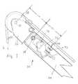
- FIG. 1illustrates a first embodiment of the invention, generally designated by reference numeral 30 .
- a device in accordance with the inventionis mounted on a jib extension 20 , as discussed above with respect to FIG. 4 .
- jib extension 20The illustration of jib extension 20 is partly broken away to show an insert 32 inserted at the tip of jib extension 20 .
- Insert 32is pivotally mounted to jib extension 20 at a pivotal mount 34 positioned at a first location.
- Mount 34may be, for example, a chrome plated pivot pin supported on extension 20 or any comparable device for permitting the insert to pivot when a force is applied.
- pin 34 or a similar elementcould be mounted on insert 32 and extend into apertures associated with jib extension 20 .
- An extended portion 36 of insert 32rotationally supports a sheave 38 on a rotational axis 40 positioned at a second location on insert 32 .
- the second location of axis 40is displaced from the first location of pivot 34 in a first direction generally parallel to the axis of jib extension 20 .
- jib insert 32The illustration of jib insert 32 is itself shown partly broken away to illustrate a load cell 42 mounted on insert 32 .
- Load cell 42is mounted on insert 32 at a third location which is spaced from the first location of pivot 34 generally along the axis of extension 20 in a direction opposite from the direction of displacement of axis 40 .
- Load cell 42bears against a block or pad 44 which is mounted on jib extension 20 .
- a load limiting devicefurther includes a jib tip computer 46 .
- the jib tip computercomprises an angle transducer as is well known for providing a signal representing the angular orientation of the insert 32 . Because the pivotal movement of insert 32 is very limited, as discussed below, the angular orientation of insert 32 corresponds closely to the angular orientation of the jib extension itself.
- a memory associated with computer 46stores data relating to the capacity of jib extension 20 to support a load. Typically, the data stored may represent limits for such load capacity, which may vary depending upon the angular orientation of the jib extension.
- Jib tip computer 46further includes a logic device for receiving and interpreting data. This may comprise, for example, a microprocessor.
- the angle transducer, memory and logic devicemay conveniently be integrated in a single device 46 , as suggested. It is within the scope of the invention, however, that these elements may be individual or distinct from each other but operatively connected in accordance with the teachings of the invention.
- a lifting cable 22 of the crane on which jib extension 20 is mountedextends along the length of jib extension 20 and passes over sheave 38 .
- the load on the crane hookimposes a force L on cable 22 , as illustrated in FIG. 1 .
- the force on cable 22imparts a torque or rotational force in insert 32 , tending to pivot insert 32 in a counter-clockwise direction about pivotal mount 34 .
- Load cell 42engaging block 44 , provides a reactive force, preventing more than minimal rotation.
- Load cell 44measures the reactive force, which represents the force imparted by the load L.
- the relationship between the force imparted by load L and the force measured by load cell 42depends, of course, on the relationship between the distance D 1 , between axis 40 and pivot 34 , to the distance D 2 , between load cell 42 and pivot 34 .
- Load cell 42 and/or logic associated with jib tip computer 46are appropriately calibrated so that the signal received from load cell 42 and acted upon by computer 46 appropriately represents the magnitude of the load force imposed by the force L on the jib extension 20 .
- the angle transducer associated with jib tip computer 46also provides a signal to the logic means of the computer.
- the logic meansreceives a signal representing the force of the load on the jib extension, and a signal representing the angular orientation thereof.
- the data represented by these signalsis compared to data stored in the memory portion of the computer representing acceptable load limits for various angular orientations. If it is determined that the load is within limits for the instant orientation, operation of the crane proceeds without interruption or incident.
- one or more signalsmay be output by the jib tip computer.
- Such signalsmay be provided to control devices, which themselves are not part of the present invention, to terminate operation of the lifting apparatus or otherwise curtail operation in a manner so as to relieve the overload and avoid a dangerous condition.
- Such signalsmay also be provided to activate a warning device, such as a light or a horn, to alert an operator to the overload condition.
- Control signals or warning signals generated by jib tip computer 46would typically be conveyed to control devices or warning devices located at the base of the crane and/or in an operators cab, normally located at the base of the crane. Such signals would normally be conveyed along the length of the jib extension and along the length of the extensible crane boom. It is common practice to equip cranes with an anti-two block device which assists an operator in keeping the hook block of a crane from being raised to high and contacting the boom tip of the crane. Various ways are known for conveying signals from an anti-two block device at the end of a boom to an operator's control panel and/or control devices at the base of the boom, including signal conductors passing through and along the boom. Such signal conductors may similarly be utilized for transferring signals from jib tip computer 46 to the control devices or control panel of the boom.
- a load limiting deviceas described, provides means for monitoring the load on a jib extension which may be added to an extensible boom, and assuring that the load capacity of the extension will not be exceeded during operation of the lifting apparatus.
- a devicethus, assures the integrity of the jib extension and enhances safety of operation.
- FIG. 2A second embodiment of the invention is illustrated in FIG. 2 . Elements corresponding to those illustrated in FIG. 1 are indicated with similar reference numerals.
- FIG. 2schematically illustrates the jib extension 20 shown cut away to reveal jib tip insert 32 pivotally mounted to the jib extension at pivotal mount 34 .
- Sheave 38is rotationally supported on insert 32 at axis 40 .
- Axis 40is spaced from the location of pivotal mount 34 in a direction generally along the axis of extension 20 at a distance D 1 .
- Load cell 42is supported on jib extension 20 .
- Load cell 42is spaced from pivotal mount 34 at a distance D 2 in a direction generally parallel to the axis of extension 20 .
- Load cell 42bears directly against a surface of jib tip insert 32 .
- load cell 42could be mounted on inset 32 and bear against a surface of jib extension 20 .
- a load on the crane hookimparts a force L on cable 22 which passes about sheave 38 .
- Thisimparts a rotational force to jib tip insert 32 , tending to rotate the insert in a clockwise direction in the view illustrated in FIG. 2 .
- Load cell 42bearing against jib tip insert 32 , prevents all but minimal rotation of the jib insert, and provides a signal representative of force L acting upon the sheave, upon the jib tip insert and, thus, upon jib extension 20 .
- jib tip computer 46also includes an angle transducer for providing a signal representing the angular orientation of the jib tip insert 32 (and, thus, the angular orientation of jib extension 20 ), as well logic means and capacity data for making a comparison between the instantaneous load and orientation of the jib extension 20 and permissible loads for such orientation.
- FIG. 3illustrates an additional embodiment of the present invention. Again, elements corresponding to those illustrated in FIGS. 1 and 2 are indicated with like reference numerals.
- jib tip insert 32is pivotally mounted at the tip of jib extension 20 on pivotal mount 34 .
- Sheave 38is rotationally mounted at axis 40 which is spaced from pivotal mount 34 at a distance D 1 generally in a direction parallel to the axis of jib extension 20 .
- Load cell 42is mounted on jib extension 20 and bears directly against a portion of jib tip insert 32 .
- load cell 42could be mounted on insert 32 and bear against a flange or other surface associated with jib extension 20 .
- Load cell 42is spaced from pivotal mount 34 a distance D 2 in a direction generally perpendicular to the axis of jib extension 20 .
- load force L on cable 22tends to cause jib insert 32 to pivot about pivotal mount 34 in a clockwise direction as illustrated in FIG. 3 .
- Load cell 42 bearing against insert 32resists all but minimal rotation of the insert, providing an appropriately calibrated signal to jib tip computer 46 .
- jib tip computer 46also receives a signal from an angle transducer associated therewith and determines whether the load on jib extension 20 is within limits for the instant angular orientation or if that load exceeds the capacity of the jib extension.
- the present inventionthus provides an economical and effective means for monitoring loads imposed upon a jib extension which may be added to a crane.
- the inventionenhances the safety of operation of the crane.
Landscapes
- Engineering & Computer Science (AREA)
- Mechanical Engineering (AREA)
- Jib Cranes (AREA)
Abstract
Description
Claims (12)
Priority Applications (1)
| Application Number | Priority Date | Filing Date | Title |
|---|---|---|---|
| US10/370,714US6843383B2 (en) | 2003-02-24 | 2003-02-24 | Jib load limiting device |
Applications Claiming Priority (1)
| Application Number | Priority Date | Filing Date | Title |
|---|---|---|---|
| US10/370,714US6843383B2 (en) | 2003-02-24 | 2003-02-24 | Jib load limiting device |
Publications (2)
| Publication Number | Publication Date |
|---|---|
| US20040164042A1 US20040164042A1 (en) | 2004-08-26 |
| US6843383B2true US6843383B2 (en) | 2005-01-18 |
Family
ID=32868207
Family Applications (1)
| Application Number | Title | Priority Date | Filing Date |
|---|---|---|---|
| US10/370,714Expired - LifetimeUS6843383B2 (en) | 2003-02-24 | 2003-02-24 | Jib load limiting device |
Country Status (1)
| Country | Link |
|---|---|
| US (1) | US6843383B2 (en) |
Cited By (21)
| Publication number | Priority date | Publication date | Assignee | Title |
|---|---|---|---|---|
| US20080019815A1 (en)* | 2005-10-05 | 2008-01-24 | Oshkosh Truck Corporation | System for monitoring load and angle for mobile lift device |
| US20080038106A1 (en)* | 2005-10-05 | 2008-02-14 | Oshkosh Truck Corporation | Mobile lift device |
| US7357263B2 (en) | 2006-03-22 | 2008-04-15 | Altec Industries, Inc. | Articulating jib |
| US20080288125A1 (en)* | 2007-05-15 | 2008-11-20 | Cameron John F | Determining an autonomous position of a point of interest on a lifting device |
| US20090083100A1 (en)* | 2007-09-26 | 2009-03-26 | Darby Jr George Derrick | Collision avoidance |
| US20090159547A1 (en)* | 2007-12-25 | 2009-06-25 | Kobelco Cranes Co., Ltd. | Boom component display apparatus |
| US20090256744A1 (en)* | 2008-04-09 | 2009-10-15 | Peter Van Wyck Loomis | circuit for exclusion zone compliance |
| US20100039317A1 (en)* | 2008-08-18 | 2010-02-18 | Cameron John F | Construction equipment component location tracking |
| US20100039262A1 (en)* | 2008-08-18 | 2010-02-18 | Cameron John F | Construction equipment component location tracking |
| US20100039319A1 (en)* | 2008-08-18 | 2010-02-18 | Cameron John F | Automated recordation of crane inspection activity |
| US20100044332A1 (en)* | 2008-08-22 | 2010-02-25 | Cameron John F | Monitoring crane component overstress |
| US20100070179A1 (en)* | 2008-09-17 | 2010-03-18 | Cameron John F | Providing an autonomous position of a point of interest to a lifting device to avoid collision |
| US20100110185A1 (en)* | 2008-10-21 | 2010-05-06 | Motion Metrics International Corp. | Method, system and apparatus for monitoring loading of a payload into a load carrying container |
| CN101244792B (en)* | 2007-03-30 | 2010-08-18 | 上海港务工程公司 | Surcharge load measuring and alarming device for crane of crane ship and measuring method thereof |
| US20100283681A1 (en)* | 2008-01-07 | 2010-11-11 | Benjamin William Remondi | Autonomous projection of global navigation satellite orbits |
| US20110081020A1 (en)* | 2008-04-09 | 2011-04-07 | Peter Van Wyck Loomis | Terrestial-signal based exclusion zone compliance |
| CN101244793B (en)* | 2007-03-30 | 2011-08-31 | 上海港务工程公司 | Surcharge load difference measuring and alarming device for crane of single-arm double-hung crane ship and measuring method thereof |
| US8103438B2 (en) | 2007-09-26 | 2012-01-24 | Trimble Navigation Limited | Method and system for automatically directing traffic on a site |
| US8813981B2 (en) | 2011-03-21 | 2014-08-26 | Oshkosh Corporation | Anti-two block system for a crane assembly |
| US8843279B2 (en) | 2011-06-06 | 2014-09-23 | Motion Metrics International Corp. | Method and apparatus for determining a spatial positioning of loading equipment |
| IT202300001827A1 (en)* | 2023-02-06 | 2024-08-06 | Jacques Tranchero | CRANE WITH A WINCH PULL LIMITATION SYSTEM. |
Families Citing this family (3)
| Publication number | Priority date | Publication date | Assignee | Title |
|---|---|---|---|---|
| CN101746675B (en)* | 2009-12-31 | 2012-05-02 | 三一汽车制造有限公司 | Crane super-lifting device and control system and control method thereof |
| SE535784C2 (en)* | 2011-02-24 | 2012-12-18 | Bergteamet Ab | Mobile crane |
| DK3257805T3 (en)* | 2016-06-13 | 2019-04-01 | Cargotec Patenter Ab | HYDRAULIC CRANE |
Citations (20)
| Publication number | Priority date | Publication date | Assignee | Title |
|---|---|---|---|---|
| US2030529A (en) | 1930-12-29 | 1936-02-11 | Nash Archibald Frazer | Safety device for cranes and the like |
| GB913507A (en)* | 1961-03-21 | 1962-12-19 | Schwermaschb Kirow Veb | Overload prevention devices for jib cranes |
| US3266638A (en) | 1965-01-19 | 1966-08-16 | Popov Constantine | Extensible jib-cranes |
| US3638781A (en) | 1970-01-30 | 1972-02-01 | Movor & Coulson Ltd | Conveyor belt-tensioning means |
| US3827514A (en) | 1973-06-25 | 1974-08-06 | Weigh Tronix | Weight measuring hook block apparatus for cranes |
| US3833130A (en) | 1973-04-20 | 1974-09-03 | Krupp Gmbh | Safety device for a top boom pivotally mounted on a crane boom |
| US3924752A (en) | 1974-07-16 | 1975-12-09 | Bwb Controls Inc | Crane boom and line safety limit warning assembly |
| US3990584A (en) | 1974-06-03 | 1976-11-09 | Strawson Hydraulics (Consultants) Limited | Electrical safety control device for a variable radius crane |
| US4003482A (en) | 1972-11-27 | 1977-01-18 | Societe Anonyme Dite: Potain Poclain Materiel | Safety device for a crane |
| US4057792A (en) | 1970-01-21 | 1977-11-08 | Ludwig Pietzsch | Overload safety device for telescopic cranes |
| US4133032A (en) | 1976-05-14 | 1979-01-02 | Pye Limited | Crane load indicating arrangement |
| US4300134A (en) | 1979-12-20 | 1981-11-10 | Eaton Corporation | Automatic resetting anti 2-block crane warning system |
| US4368824A (en) | 1979-05-18 | 1983-01-18 | Coles Cranes Limited | Safe load indicator |
| US4413691A (en) | 1981-10-23 | 1983-11-08 | Quest Corporation | Sheave block weighing assembly |
| US4509376A (en) | 1979-05-18 | 1985-04-09 | Coles Cranes Limited | Safe load indicator |
| JPH04112190A (en)* | 1990-07-17 | 1992-04-14 | Kobe Steel Ltd | Turning crane |
| US5645181A (en) | 1992-02-12 | 1997-07-08 | Kato Works Co., Ltd. | Method for detecting a crane hook lifting distance |
| US5711440A (en) | 1993-11-08 | 1998-01-27 | Komatsu Ltd. | Suspension load and tipping moment detecting apparatus for a mobile crane |
| US6044991A (en) | 1995-06-21 | 2000-04-04 | Altec Industries, Inc. | Load measuring apparatus for aerial booms and jibs |
| US6170681B1 (en) | 1998-07-21 | 2001-01-09 | Kabushiki Kaisha Kobe Seiko Sho (Kobe Steel, Ltd.) Steel | Swing type machine and method for setting a safe work area and a rated load in same |
- 2003
- 2003-02-24USUS10/370,714patent/US6843383B2/ennot_activeExpired - Lifetime
Patent Citations (20)
| Publication number | Priority date | Publication date | Assignee | Title |
|---|---|---|---|---|
| US2030529A (en) | 1930-12-29 | 1936-02-11 | Nash Archibald Frazer | Safety device for cranes and the like |
| GB913507A (en)* | 1961-03-21 | 1962-12-19 | Schwermaschb Kirow Veb | Overload prevention devices for jib cranes |
| US3266638A (en) | 1965-01-19 | 1966-08-16 | Popov Constantine | Extensible jib-cranes |
| US4057792A (en) | 1970-01-21 | 1977-11-08 | Ludwig Pietzsch | Overload safety device for telescopic cranes |
| US3638781A (en) | 1970-01-30 | 1972-02-01 | Movor & Coulson Ltd | Conveyor belt-tensioning means |
| US4003482A (en) | 1972-11-27 | 1977-01-18 | Societe Anonyme Dite: Potain Poclain Materiel | Safety device for a crane |
| US3833130A (en) | 1973-04-20 | 1974-09-03 | Krupp Gmbh | Safety device for a top boom pivotally mounted on a crane boom |
| US3827514A (en) | 1973-06-25 | 1974-08-06 | Weigh Tronix | Weight measuring hook block apparatus for cranes |
| US3990584A (en) | 1974-06-03 | 1976-11-09 | Strawson Hydraulics (Consultants) Limited | Electrical safety control device for a variable radius crane |
| US3924752A (en) | 1974-07-16 | 1975-12-09 | Bwb Controls Inc | Crane boom and line safety limit warning assembly |
| US4133032A (en) | 1976-05-14 | 1979-01-02 | Pye Limited | Crane load indicating arrangement |
| US4368824A (en) | 1979-05-18 | 1983-01-18 | Coles Cranes Limited | Safe load indicator |
| US4509376A (en) | 1979-05-18 | 1985-04-09 | Coles Cranes Limited | Safe load indicator |
| US4300134A (en) | 1979-12-20 | 1981-11-10 | Eaton Corporation | Automatic resetting anti 2-block crane warning system |
| US4413691A (en) | 1981-10-23 | 1983-11-08 | Quest Corporation | Sheave block weighing assembly |
| JPH04112190A (en)* | 1990-07-17 | 1992-04-14 | Kobe Steel Ltd | Turning crane |
| US5645181A (en) | 1992-02-12 | 1997-07-08 | Kato Works Co., Ltd. | Method for detecting a crane hook lifting distance |
| US5711440A (en) | 1993-11-08 | 1998-01-27 | Komatsu Ltd. | Suspension load and tipping moment detecting apparatus for a mobile crane |
| US6044991A (en) | 1995-06-21 | 2000-04-04 | Altec Industries, Inc. | Load measuring apparatus for aerial booms and jibs |
| US6170681B1 (en) | 1998-07-21 | 2001-01-09 | Kabushiki Kaisha Kobe Seiko Sho (Kobe Steel, Ltd.) Steel | Swing type machine and method for setting a safe work area and a rated load in same |
Cited By (35)
| Publication number | Priority date | Publication date | Assignee | Title |
|---|---|---|---|---|
| US20080038106A1 (en)* | 2005-10-05 | 2008-02-14 | Oshkosh Truck Corporation | Mobile lift device |
| US7489098B2 (en) | 2005-10-05 | 2009-02-10 | Oshkosh Corporation | System for monitoring load and angle for mobile lift device |
| US20080019815A1 (en)* | 2005-10-05 | 2008-01-24 | Oshkosh Truck Corporation | System for monitoring load and angle for mobile lift device |
| US7683564B2 (en) | 2005-10-05 | 2010-03-23 | Oshkosh Corporation | System for monitoring load and angle for mobile lift device |
| US7357263B2 (en) | 2006-03-22 | 2008-04-15 | Altec Industries, Inc. | Articulating jib |
| CN101244793B (en)* | 2007-03-30 | 2011-08-31 | 上海港务工程公司 | Surcharge load difference measuring and alarming device for crane of single-arm double-hung crane ship and measuring method thereof |
| CN101244792B (en)* | 2007-03-30 | 2010-08-18 | 上海港务工程公司 | Surcharge load measuring and alarming device for crane of crane ship and measuring method thereof |
| US9156167B2 (en) | 2007-05-15 | 2015-10-13 | Trimble Navigation Limited | Determining an autonomous position of a point of interest on a lifting device |
| US20080288125A1 (en)* | 2007-05-15 | 2008-11-20 | Cameron John F | Determining an autonomous position of a point of interest on a lifting device |
| US8144000B2 (en) | 2007-09-26 | 2012-03-27 | Trimble Navigation Limited | Collision avoidance |
| US8103438B2 (en) | 2007-09-26 | 2012-01-24 | Trimble Navigation Limited | Method and system for automatically directing traffic on a site |
| US8239125B2 (en) | 2007-09-26 | 2012-08-07 | Trimble Navigation Limited | Method and system for automatically directing traffic on a site |
| US20090083100A1 (en)* | 2007-09-26 | 2009-03-26 | Darby Jr George Derrick | Collision avoidance |
| US7810659B2 (en)* | 2007-12-25 | 2010-10-12 | Kobelco Cranes Co., Ltd. | Boom component display apparatus |
| US20090159547A1 (en)* | 2007-12-25 | 2009-06-25 | Kobelco Cranes Co., Ltd. | Boom component display apparatus |
| US20100283681A1 (en)* | 2008-01-07 | 2010-11-11 | Benjamin William Remondi | Autonomous projection of global navigation satellite orbits |
| US8081108B2 (en) | 2008-01-07 | 2011-12-20 | Trimble Navigation Limited | Autonomous projection of global navigation satellite orbits |
| US8054181B2 (en) | 2008-04-09 | 2011-11-08 | Trimble Navigation Limited | Terrestial-signal based exclusion zone compliance |
| US20090256744A1 (en)* | 2008-04-09 | 2009-10-15 | Peter Van Wyck Loomis | circuit for exclusion zone compliance |
| US7898409B2 (en) | 2008-04-09 | 2011-03-01 | Trimble Navigation Limited | Circuit for exclusion zone compliance |
| US20110081020A1 (en)* | 2008-04-09 | 2011-04-07 | Peter Van Wyck Loomis | Terrestial-signal based exclusion zone compliance |
| US20100039262A1 (en)* | 2008-08-18 | 2010-02-18 | Cameron John F | Construction equipment component location tracking |
| US8514058B2 (en) | 2008-08-18 | 2013-08-20 | Trimble Navigation Limited | Construction equipment component location tracking |
| US7911379B2 (en) | 2008-08-18 | 2011-03-22 | Trimble Navigation Limited | Construction equipment component location tracking |
| US20100039317A1 (en)* | 2008-08-18 | 2010-02-18 | Cameron John F | Construction equipment component location tracking |
| US8224518B2 (en) | 2008-08-18 | 2012-07-17 | Trimble Navigation Limited | Automated recordation of crane inspection activity |
| US20100039319A1 (en)* | 2008-08-18 | 2010-02-18 | Cameron John F | Automated recordation of crane inspection activity |
| US20100044332A1 (en)* | 2008-08-22 | 2010-02-25 | Cameron John F | Monitoring crane component overstress |
| US20100070179A1 (en)* | 2008-09-17 | 2010-03-18 | Cameron John F | Providing an autonomous position of a point of interest to a lifting device to avoid collision |
| US8405721B2 (en) | 2008-10-21 | 2013-03-26 | Motion Metrics International Corp. | Method, system and apparatus for monitoring loading of a payload into a load carrying container |
| US20100110185A1 (en)* | 2008-10-21 | 2010-05-06 | Motion Metrics International Corp. | Method, system and apparatus for monitoring loading of a payload into a load carrying container |
| US8813981B2 (en) | 2011-03-21 | 2014-08-26 | Oshkosh Corporation | Anti-two block system for a crane assembly |
| US8843279B2 (en) | 2011-06-06 | 2014-09-23 | Motion Metrics International Corp. | Method and apparatus for determining a spatial positioning of loading equipment |
| IT202300001827A1 (en)* | 2023-02-06 | 2024-08-06 | Jacques Tranchero | CRANE WITH A WINCH PULL LIMITATION SYSTEM. |
| WO2024165962A1 (en)* | 2023-02-06 | 2024-08-15 | Jacques Tranchero | Crane with a system for limiting the pull of the winch |
Also Published As
| Publication number | Publication date |
|---|---|
| US20040164042A1 (en) | 2004-08-26 |
Similar Documents
| Publication | Publication Date | Title |
|---|---|---|
| US6843383B2 (en) | Jib load limiting device | |
| EP0535339B1 (en) | Load moment indicator system | |
| US10472214B2 (en) | Crane and method for monitoring the overload protection of such a crane | |
| KR100936120B1 (en) | Safety control system of crane using roller type load detector | |
| US7677401B2 (en) | Load monitoring and control system with selective boom-up lockout | |
| US10597266B2 (en) | Crane and method for monitoring the overload protection of such a crane | |
| EP2298689A2 (en) | Method and device for limiting lifting moment of a loading crane | |
| US20140330481A1 (en) | Device and Method for Ascertaining and Monitoring an Assembled Counterweight on a Crane | |
| US10919739B2 (en) | Overload preventing device | |
| US11192762B2 (en) | Crane with overload safety device | |
| US20070083312A1 (en) | Overload warning means for excavators | |
| US4906981A (en) | Method and apparatus for monitoring the effective load carried by a crane | |
| JP3447410B2 (en) | Truck overload protection device with crane | |
| JP4951311B2 (en) | In-vehicle crane overturn prevention device | |
| EP1150019B1 (en) | Counter for registering the quantity of lifts of a crane | |
| JPH07285787A (en) | Overload preventing device for crane | |
| RU2271332C2 (en) | Boom load-lifting crane protection method | |
| EP1798188B1 (en) | Hydraulic crane and method of registration. | |
| EP0358343A1 (en) | Crane with overload detector | |
| EP1151958B1 (en) | Hydraulic crane | |
| RU56887U1 (en) | LOAD CRANE SAFETY SYSTEM | |
| JPH0663577U (en) | crane | |
| JP2873498B2 (en) | Boom-type work vehicle safety device | |
| JP7643155B2 (en) | Loading truck crane | |
| FI83205C (en) | ANORDING FOER SKYDD AV LASTLYFTMEKANISMER MOT OEVERBELASTNING OCH VAENDNING. |
Legal Events
| Date | Code | Title | Description |
|---|---|---|---|
| AS | Assignment | Owner name:NATIONAL CRANE CORPORATION, NEBRASKA Free format text:ASSIGNMENT OF ASSIGNORS INTEREST;ASSIGNORS:SCHNEIDER, WILLIAM DENNIS;FISCHER, MAX;REEL/FRAME:013803/0768 Effective date:20030217 | |
| STCF | Information on status: patent grant | Free format text:PATENTED CASE | |
| FPAY | Fee payment | Year of fee payment:4 | |
| AS | Assignment | Owner name:JPMORGAN CHASE BANK, N.A., AS AGENT, ILLINOIS Free format text:SECURITY AGREEMENT;ASSIGNOR:GROVE U.S. L.L.C.;REEL/FRAME:022399/0511 Effective date:20080414 Owner name:JPMORGAN CHASE BANK, N.A., AS AGENT,ILLINOIS Free format text:SECURITY AGREEMENT;ASSIGNOR:GROVE U.S. L.L.C.;REEL/FRAME:022399/0511 Effective date:20080414 | |
| AS | Assignment | Owner name:GROVE U.S., L.L.C., PENNSYLVANIA Free format text:RELEASE OF SECURITY INTERESTIN U.S. PATENTS;ASSIGNOR:JPMORGAN CHASE BANK, N.A., AS AGENT;REEL/FRAME:022416/0063 Effective date:20081106 Owner name:GROVE U.S., L.L.C.,PENNSYLVANIA Free format text:RELEASE OF SECURITY INTEREST IN U.S. PATENTS;ASSIGNOR:JPMORGAN CHASE BANK, N.A., AS AGENT;REEL/FRAME:022416/0063 Effective date:20081106 Owner name:GROVE U.S., L.L.C., PENNSYLVANIA Free format text:RELEASE OF SECURITY INTEREST IN U.S. PATENTS;ASSIGNOR:JPMORGAN CHASE BANK, N.A., AS AGENT;REEL/FRAME:022416/0063 Effective date:20081106 | |
| AS | Assignment | Owner name:GROVE U.S. L.L.C., PENNSYLVANIA Free format text:MERGER;ASSIGNOR:NATIONAL CRANE CORPORATION;REEL/FRAME:025848/0296 Effective date:20091215 | |
| FPAY | Fee payment | Year of fee payment:8 | |
| AS | Assignment | Owner name:WELLS FARGO BANK, NATIONAL ASSOCIATION, AS AGENT, Free format text:SECURITY INTEREST;ASSIGNOR:GROVE U.S. L.L.C.;REEL/FRAME:037887/0881 Effective date:20160303 | |
| AS | Assignment | Owner name:GROVE U.S., L.L.C., PENNSYLVANIA Free format text:RELEASE BY SECURED PARTY;ASSIGNOR:JPMORGAN CHASE BANK, N.A., AS COLLATERAL AGENT;REEL/FRAME:038007/0285 Effective date:20160303 | |
| AS | Assignment | Owner name:WELLS FARGO BANK, NATIONAL ASSOCIATION, NEW YORK Free format text:SECURITY INTEREST;ASSIGNOR:GROVE U.S. L.L.C;REEL/FRAME:038382/0911 Effective date:20160303 | |
| FPAY | Fee payment | Year of fee payment:12 | |
| AS | Assignment | Owner name:GROVE U.S. L.L.C., PENNSYLVANIA Free format text:RELEASE BY SECURED PARTY;ASSIGNOR:WELLS FARGO BANK, NATIONAL ASSOCIATION;REEL/FRAME:048693/0515 Effective date:20190325 | |
| AS | Assignment | Owner name:MANITOWOC CRANE COMPANIES, LLC, WISCONSIN Free format text:RELEASE OF SECURITY INTERESTS;ASSIGNOR:WELLS FARGO BANK, NATIONAL ASSOCIATION;REEL/FRAME:048698/0521 Effective date:20190325 Owner name:GROVE U.S. L.L.C., PENNSYLVANIA Free format text:RELEASE OF SECURITY INTERESTS;ASSIGNOR:WELLS FARGO BANK, NATIONAL ASSOCIATION;REEL/FRAME:048698/0521 Effective date:20190325 Owner name:MANITOWOC CRANES, LLC, WISCONSIN Free format text:RELEASE OF SECURITY INTERESTS;ASSIGNOR:WELLS FARGO BANK, NATIONAL ASSOCIATION;REEL/FRAME:048698/0521 Effective date:20190325 Owner name:THE MANITOWOC COMPANY, INC., WISCONSIN Free format text:RELEASE OF SECURITY INTERESTS;ASSIGNOR:WELLS FARGO BANK, NATIONAL ASSOCIATION;REEL/FRAME:048698/0521 Effective date:20190325 | |
| AS | Assignment | Owner name:U.S. BANK NATIONAL ASSOCIATION, AS NOTES COLLATERA Free format text:SECURITY AGREEMENT;ASSIGNORS:GROVE U.S. L.L.C.;MANITOWOC CRANE COMPANIES, LLC;REEL/FRAME:048709/0202 Effective date:20190325 Owner name:U.S. BANK NATIONAL ASSOCIATION, AS NOTES COLLATERAL AGENT, MINNESOTA Free format text:SECURITY AGREEMENT;ASSIGNORS:GROVE U.S. L.L.C.;MANITOWOC CRANE COMPANIES, LLC;REEL/FRAME:048709/0202 Effective date:20190325 | |
| AS | Assignment | Owner name:JPMORGAN CHASE BANK, N.A., AS ADMINISTRATIVE AGENT Free format text:SECURITY INTEREST;ASSIGNOR:GROVE U.S. LLC;REEL/FRAME:048723/0155 Effective date:20190325 | |
| AS | Assignment | Owner name:GROVE U.S. L.L.C., PENNSYLVANIA Free format text:RELEASE BY SECURED PARTY;ASSIGNOR:U.S. BANK TRUST COMPANY, NATIONAL ASSOCIATION (AS SUCCESSOR IN INTEREST TO U.S. BANK NATIONAL ASSOCIATION);REEL/FRAME:068997/0782 Effective date:20240919 Owner name:MANITOWOC CRANE COMPANIES, LLC, WISCONSIN Free format text:RELEASE BY SECURED PARTY;ASSIGNOR:U.S. BANK TRUST COMPANY, NATIONAL ASSOCIATION (AS SUCCESSOR IN INTEREST TO U.S. BANK NATIONAL ASSOCIATION);REEL/FRAME:068997/0782 Effective date:20240919 |