US6842335B1 - Multifunctional cover integrated into sub-panel of portable electronic device - Google Patents
Multifunctional cover integrated into sub-panel of portable electronic deviceDownload PDFInfo
- Publication number
- US6842335B1 US6842335B1US09/993,732US99373201AUS6842335B1US 6842335 B1US6842335 B1US 6842335B1US 99373201 AUS99373201 AUS 99373201AUS 6842335 B1US6842335 B1US 6842335B1
- Authority
- US
- United States
- Prior art keywords
- cover
- housing
- personal digital
- digital assistant
- coupled
- Prior art date
- Legal status (The legal status is an assumption and is not a legal conclusion. Google has not performed a legal analysis and makes no representation as to the accuracy of the status listed.)
- Expired - Lifetime, expires
Links
Images


Classifications
- G—PHYSICS
- G06—COMPUTING OR CALCULATING; COUNTING
- G06F—ELECTRIC DIGITAL DATA PROCESSING
- G06F1/00—Details not covered by groups G06F3/00 - G06F13/00 and G06F21/00
- G06F1/16—Constructional details or arrangements
- G06F1/1613—Constructional details or arrangements for portable computers
- G06F1/1633—Constructional details or arrangements of portable computers not specific to the type of enclosures covered by groups G06F1/1615 - G06F1/1626
- G06F1/1656—Details related to functional adaptations of the enclosure, e.g. to provide protection against EMI, shock, water, or to host detachable peripherals like a mouse or removable expansions units like PCMCIA cards, or to provide access to internal components for maintenance or to removable storage supports like CDs or DVDs, or to mechanically mount accessories
- G—PHYSICS
- G06—COMPUTING OR CALCULATING; COUNTING
- G06F—ELECTRIC DIGITAL DATA PROCESSING
- G06F1/00—Details not covered by groups G06F3/00 - G06F13/00 and G06F21/00
- G06F1/16—Constructional details or arrangements
- G06F1/1613—Constructional details or arrangements for portable computers
- G06F1/1626—Constructional details or arrangements for portable computers with a single-body enclosure integrating a flat display, e.g. Personal Digital Assistants [PDAs]
- G—PHYSICS
- G06—COMPUTING OR CALCULATING; COUNTING
- G06F—ELECTRIC DIGITAL DATA PROCESSING
- G06F1/00—Details not covered by groups G06F3/00 - G06F13/00 and G06F21/00
- G06F1/16—Constructional details or arrangements
- G06F1/1613—Constructional details or arrangements for portable computers
- G06F1/1632—External expansion units, e.g. docking stations
- G—PHYSICS
- G06—COMPUTING OR CALCULATING; COUNTING
- G06F—ELECTRIC DIGITAL DATA PROCESSING
- G06F2200/00—Indexing scheme relating to G06F1/04 - G06F1/32
- G06F2200/16—Indexing scheme relating to G06F1/16 - G06F1/18
- G06F2200/163—Indexing scheme relating to constructional details of the computer
- G06F2200/1634—Integrated protective display lid, e.g. for touch-sensitive display in handheld computer
Definitions
- the present inventionrelates to the field of portable electronic devices, such as personal digital assistants or palmtop computer systems. Specifically, the present invention relates to expanded functionality for a cover over an expansion port in a portable electronic device.
- a portable computer systemsuch as a personal digital assistant (PDA) or palmtop
- PDApersonal digital assistant
- palmtopis an electronic device that is small enough to be held in the hand of a user and is thus “palm-sized.”
- PDApersonal digital assistant
- palmtopis an electronic device that is small enough to be held in the hand of a user and is thus “palm-sized.”
- portable computer systemsare lightweight and so are exceptionally portable and convenient.
- Wireless technologiesare widely used for communication in modern society.
- personal cordless phonese.g., cell phones
- pagersportable computer systems
- transceiverscapable of broadcasting wireless signals (e.g., radio signals) over relatively long distances.
- the present inventionprovides a design for expanding the functionality of portable electronic devices that will not increase the size or shape of the device. Specifically, the present invention provides expanded functionality to existing covers for openings in portable electronic devices.
- the present inventionpertains to a cover for an opening in the housing of an electronic device that performs a function in addition to protecting the contacts and circuitry contained within the opening in the device.
- a surface of the portable electronic device housinge.g., the back side or bottom surface
- the recessed openingis enclosed with a cover to protect the enclosure from dust or dirt that might be harmful to the connectors and circuitry within the opening.
- the coveris coupled to the housing in a way that allows the cover to move between a first and second position or to be removed.
- the coverwhen stored within the surface recess, is flush with the portable electronic device housing and becomes part of the housing so that the current form factor (size, shape and appearance) of the electronic device is generally retained.
- the coveris removeably coupled to the housing, and the cover can be removed from the surface recess of the housing and replaced in the surface recess of the housing.
- the coveris pivotably coupled to the housing, and the cover can be moved to various positions about the pivot point.
- the coveris hingeably coupled to the housing, and the cover can be moved to various positions about the hinge or joint.
- the coveris slideably coupled to the housing, and the cover can be moved to various positions by sliding it.
- the cover over the opening in the housingcontains an antenna that is coupled to a transceiver by a suitable means.
- connectorsare contained in the opening in the housing of the electronic device for connecting the transceiver or other appropriate circuitry to the cover.
- an expansion cardconnects to the device and contains connectors for further connecting to the cover.
- the covercontains a speaker. In another embodiment, the cover illuminates to apprise the user of an awaiting message, for example. In another embodiment, the cover vibrates for alerting the user of an awaiting message. In another embodiment, the cover contains an external display such as a date and time display. In yet another embodiment, the cover has an external connector for accepting additional expansion capability.
- covers over openings in electronic devicescan be utilized for additional functionality.
- the form factor (size, shape and appearance) of existing hand-held devicescan be retained.
- FIG. 1is a block diagram of an exemplary computer system in accordance with one embodiment of the present invention.
- FIG. 2is a topside perspective view of a portable electronic device in accordance with one embodiment of the present invention.
- FIG. 3is a bottom side perspective view of the portable electronic device of FIG. 2 .
- FIG. 4is an exploded view of the electronic device of FIG. 3 according to one embodiment of the present invention.
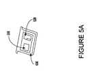
- FIG. 5Aillustrates a port cover containing an antenna and a printed circuit board according to one embodiment of the present invention.
- FIG. 5Billustrates a port cover containing a display device according to one embodiment of the present invention.
- FIG. 5Cillustrates a port cover as a speaker according to one embodiment of the present invention.
- FIG. 5Dillustrates a port cover as a vibrating alarm according to one embodiment of the present invention.
- FIG. 5Eillustrates a port cover as an illuminating alarm according to one embodiment of the present invention.
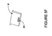
- FIG. 5Fillustrates a port cover with an expansion port according to one embodiment of the present invention.
- FIG. 6is an exploded view of the electronic device of FIG. 3 illustrating the cover connected to the electronic device through an expansion card in accordance with one embodiment of the present invention.
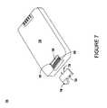
- FIG. 7is an exploded back side perspective view of a portable electronic device with an edge opening and cover in accordance with one embodiment of the present invention.
- the present inventionis described primarily in the context of a portable computer system, often times referred to as a palm top, handheld or personal digital assistant. However, it is understood that the present invention is not limited to implementation in portable computer systems, but can also be implemented in other portable electronic devices such as cell phones, laptops, global positioning system devices, and the like. Indeed, aspects of the present invention can be implemented in any device, including desktop computer systems, in which it is necessary or desirable to maintain a certain form factor while introducing additional functionality.
- FIG. 1is a block diagram of one embodiment of a portable computer system 100 upon which embodiments of the present invention may be implemented.
- Portable computer system 100includes an address/data bus 150 for communicating information, a central processor 101 coupled with the bus for processing information and instructions, a volatile memory 102 (e.g. random access memory, RAM) coupled with the bus 150 for storing information and instructions for the central processor 101 and a non-volatile memory 103 (e.g., read only memory, ROM) coupled with the bus 150 for storing static information and instructions for the processor 101 .
- Computer system 100also includes an optional data storage device 104 (e.g., memory stick) coupled with the bus 150 for storing information and instructions. Device 104 can be removable.
- computer system 100also contains a display device 105 coupled to the bus 150 for displaying information to the computer user.
- computer system 100also includes an optional signal transmitter/receiver device 108 , which is coupled to bus 150 for providing a physical communication link between computer system 100 , and a network environment.
- signal transmitter/receiver device 108enables central processor unit 101 to communicate wirelessly with other electronic systems coupled to a network.
- computer system 100also includes an optional expansion port for use with various types of expansion cards.
- the expansion cardsperform a variety of functions, depending upon the circuits that they contain.
- the expansion port 410is usually embodied as an opening in the housing of computer system 100 with a cover 85 which is attached to the housing and which can be opened or removed to replace the expansion card.
- the function of the cover 85is to protect the card and connectors that it covers from dust and dirt which could be harmful to the enclosed circuitry.
- signal input/output communications device 108is a transmitter/receiver (transceiver) that is coupled through bus 150 to cover 85 .
- cover 85functions as an antenna that provides the functionality to transmit and receive information over a wireless communication interface.
- Cover 85can, in other embodiments, function with the processor through bus 150 to generate alarms, function as a speaker, and display information.
- Computer system 100 of FIG. 1Also included in computer system 100 of FIG. 1 is an optional alphanumeric input device 106 that in one implementation is a handwriting recognition pad. Alphanumeric input device 106 can communicate information and command selections to processor 101 .
- Computer system 100also includes an optional cursor control or directing device (on-screen cursor control 107 ) coupled to bus 150 for communicating user input information and command selections to processor 101 .
- FIG. 2is a perspective illustration of the top face 100 a of one embodiment of the palmtop computer system 100 of the present invention.
- the top face 100 acontains a display screen 105 surrounded by a bezel or cover.
- a removable stylus 80is also shown.
- top face 100 ais formed with a recess 24 for holding stylus 80 .
- the display screen 105is a touch screen able to register contact between the screen and the tip of the stylus 80 .
- the stylus 80can be of any material to make contact with the screen 105 .
- the top face 100 aalso contains one or more dedicated and/or programmable buttons 75 for selecting information and causing the computer system to implement functions.
- the on/off button 95is also shown.
- FIG. 2also illustrates a handwriting recognition pad or “digitizer” containing two regions 106 a and 106 b .
- Region 106 ais for the drawing of alphabetic characters therein (and not for numeric characters) for automatic recognition
- region 106 bis for the drawing of numeric characters therein (and not for alphabetic characters) for automatic recognition.
- the stylus 80is used for stroking a character within one of the regions 106 a and 106 b .
- the stroke informationis then fed to an internal processor for automatic character recognition. Once characters are recognized, they are typically displayed on the screen 105 for verification and/or modification.
- FIG. 3illustrates the bottom side 100 b of one embodiment of the palmtop computer system 100 that can be used in accordance with various embodiments of the present invention.
- a communication interface 180is also shown.
- the communication interface 180is a serial communication port, but could also alternatively be of any of a number of well-known communication standards and protocols, e.g., parallel, SCSI (small computer system interface), Firewire (IEEE 1394), Ethernet, etc.
- a battery storage compartment door 90Also shown is also shown.
- portable computer system 100includes an expansion port 410 with a cover 85 .
- cover 85is coupled to the housing so that it can be moved or removed in order to access the expansion port beneath.
- cover 85can also be implemented in other types of electronic devices in accordance with the present invention.
- cover 85is shown in the closed position. In the closed position, cover 85 is located within a recess 84 that is formed in the housing 87 of portable computer system 100 .
- Recess 84is of a size and shape to accommodate cover 85 , such that cover 85 fits into recess 84 and does not protrude from housing 87 . That is, cover 85 is flush with housing 87 , such that the profile of housing 87 is not changed when cover 85 is in the closed position.
- cover 85is illustrated as a rectangular shape in FIG. 3 , it is appreciated that cover 85 is not limited to this shape.
- recess 84 and cover 85can be approximately the same size and shape, or they can be of different sizes and shapes provided that cover 85 fits within recess 84 when in the closed position.
- the current form factor (size, shape and appearance) of the hand-held devicee.g., portable computer system 100 ) is generally retained.
- multifunctional cover 85is coupled to the housing 87 in a way that allows the cover 85 to move between a first (closed) and a second (open) position.
- cover 85is hingeably coupled to the housing 87 using a hinge joint 83 .
- cover 85can be rotated about hinge or joint 83 to a closed or open position.
- cover 85can be hingeably coupled to housing 87 by pins 82 a and 82 b ; in this embodiment, cover 85 can be rotated about pins 82 a and 82 b to a closed or open position.
- Pins 82 a and 82 bcan also serve to provide an electrical connection between cover 85 and portable computer system 100 .
- cover 85 of FIG. 3can be pivotably coupled to housing 87 by a single pin (e.g., pin 82 a ) or by some other means that functions in a similar fashion. In this embodiment, cover 85 can be pivoted about the pivot point (e.g., pin 82 a ) to a stored or deployed position. In another embodiment, cover 85 is slideably coupled to the housing 87 . In this embodiment, cover 85 is slid to a closed or open position along guides formed within recess 84 .
- cover 85is removeably coupled to the housing 87 .
- cover 85can be slid along guides formed within the recess 84 and removed from housing 87 to allow maximum access to the expansion port 410 .
- FIG. 4illustrates an exploded view of the bottom side 100 b of the palmtop computer device of FIG. 3 in accordance with one embodiment.
- the housing 87 of the palmtop computer devicecontains an opening 410 which contains contacts 420 which are coupled to bus 150 of computer system 100 of FIG. 1 .
- the opening 410accommodates a cover 85 .
- the topside of the cover 85is of the same material as the housing 87 and, when in the closed position, forms part of the housing 87 .
- the bottom side 430 of the cover 85contains tracings for circuitry 440 and contacts. 450 for connecting with contacts 420 and for connecting with bus 150 of computer system 100 of FIG. 1 .
- the circuitry in this embodimentcould be that of an antenna for communicating with a transceiver for access to a wireless network or to other radio signals.
- FIGS. 5A-5F and 6are perspective drawings showing various embodiments of the present invention. Although the embodiments of FIGS. 5A-5F and 6 are separately described in order to more clearly illustrate certain aspects of the present invention, it is appreciated that combinations of these embodiments may also be used. For example, functions shown in FIGS. 5A-5F and 6 as being performed separately may be combined.
- cover 85a bottom view of cover 85 , according to one embodiment of the present invention, is illustrated.
- the bottom side 430 of cover 85contains a component 510 such as an integrated circuit (ICU) containing circuitry (e.g., transmitter/receiver device circuitry) for supporting the particular function being performed by cover 85 .
- a component 510such as an integrated circuit (ICU) containing circuitry (e.g., transmitter/receiver device circuitry) for supporting the particular function being performed by cover 85 .
- an antenna 520for coupling to component 510 for wireless communication.
- FIG. 5Billustrates a view showing the external surface of cover 85 .
- cover 85in concert with circuitry as illustrated by component 510 of FIG. 5A , functions as a display device 530 .
- display device 530is illustrated as a digital clock, it is appreciated that display device 530 is not limited to this function, but can assume the functionality as defined by the PCB 510 and a preconfigured display.
- FIG. 5Cillustrates a view showing the external surface of cover 85 .
- cover 85functions as a speaker 540 .
- a speaker 540is contained within the cover 85 for converting radio signals or digital signals to sound.
- FIG. 5Dillustrates a view showing the external surface of cover 85 .
- cover 85functions as a vibrating alarm.
- cover 85upon receiving an alarm signal from a processor, cover 85 vibrates 550 to alert a user that an alarm message awaits.
- This alarm vibration 550could be in response to a user preset time alarm, a battery-low alarm, or any of a multitude of alarms for which the processor is preconfigured to signal.
- cover 85is illustrated as an illuminating alarm device.
- an illuminating panel 560is contained within the topside of cover 85 .
- the circuitry contained within the component 510 of FIG. 5Awould cause the illumination of panel 560 for alerting a user of an alarm message.
- FIG. 5Fillustrates a view showing the external surface of cover 85 .
- cover 85contains an expansion port 570 for coupling to an external expansion device or card.
- FIG. 6is an exploded view of the bottom view 100 b of the palm top computer device 100 of FIG. 3 , according to one embodiment of the present invention.
- the housing 87 of the palmtop computer device 100contains an opening 410 which contains contacts 610 which are coupled to bus 150 of computer system 100 of FIG. 1 .
- the opening 410accommodates one or more expansion cards 620 and a removable cover 85 according to the present embodiment.
- the topside (external surface) of the cover 85is of the same material as the housing 87 and, when in the closed position, forms part of the housing 87 .
- the contacts 610are for receiving one or more cards 620 such as, but not limited to, memory expansion cards, Secure Identity Module (SIM) cards or I/O cards (e.g., Bluetooth cards or IEEE 802.11 cards).
- Card 620has contacts 420 that connect to contacts 440 on the backside 425 (internal surface) of cover 85 .
- card 620is a radio-signal-range wireless transceiver such as a Bluetooth or IEEE 802.11b, and the circuitry 450 in the cover 85 contains an antenna of the appropriate impedance for the frequency of the device of card 620 .
- card 620is an IEEE 802.11a card and the cover 85 contains an antenna of required impedance for the frequency of the IEEE 802.11a card.
- the cover 85is removable and can be replaced by a cover 85 of the same dimensions but having different functionality, In order to distinguish the functionality of a removable cover 85 , according to one embodiment, the cover 85 is color coded to delineate functionality.
- cover 85may receive a clock signal from portable computer system 100 , or cover 85 may comprise its own clock.
- FIG. 7an exploded view of a handheld electronic device 700 is shown, according to another embodiment of the present invention.
- Device 700is contained in housing 710 .
- housing 710At the edge of housing 710 is an expansion port 720 containing connectors 750 and contacts 760 .
- Contacts 760also connect to the bus of device 700 .
- the cover 730 and protrusion 740are of the same material as the housing 710 and fit flush with the housing 710 when in the closed position.
- the cover 730contains an antenna within the protrusion 740 that connects to the bus of device 700 through contacts 770 when in the closed position.
- a cover for an opening in the housing of a portable electronic devicethat provides a function in addition to that of protecting the opening from dirt, has the advantage of expanded functionality without appreciably altering the form factor of the device.
- the covercan be removed, according to one embodiment, and can be interchanged with another cover of the same dimensions but with different functionality.
- a device having a Bluetooth transceiver and a cover functioning as a Bluetooth-compatible antennacould have the transceiver changed to IEEE 802.11a and the cover could easily be replaced with one that functions as an IEEE 802.11a-compatible antenna.
- a cover that functions as a vibrating alarmcould easily be replaced with one that includes a digital clock display.
- the coverscan have multiple functions.
- a cover functioning as an antennacould also contain the circuitry for a transceiver.
- a cover functioning as a speakercould also vibrate to issue an alarm.
- theycan be coloring coded, silk screened with identifying labels or otherwise labeled for identification of functionality.
- the present inventionprovides a design for expanding the functionality of portable electronic devices that will not increase the size or shape of the device. Specifically, the present invention provides expanded functionality to existing covers for openings in portable electronic devices.
Landscapes
- Engineering & Computer Science (AREA)
- Theoretical Computer Science (AREA)
- Computer Hardware Design (AREA)
- General Engineering & Computer Science (AREA)
- Human Computer Interaction (AREA)
- Physics & Mathematics (AREA)
- General Physics & Mathematics (AREA)
- Telephone Set Structure (AREA)
- Casings For Electric Apparatus (AREA)
Abstract
Description
Claims (22)
Priority Applications (4)
| Application Number | Priority Date | Filing Date | Title |
|---|---|---|---|
| US09/993,732US6842335B1 (en) | 2001-11-21 | 2001-11-21 | Multifunctional cover integrated into sub-panel of portable electronic device |
| US10/794,699US7154746B1 (en) | 2001-11-21 | 2004-03-03 | Multifunctional cover integrated into sub-panel of portable electronic device |
| US11/644,223US7551429B1 (en) | 2001-11-21 | 2006-12-22 | Multifunctional cover integrated into sub-panel of portable electronic device |
| US12/463,290US8270149B2 (en) | 2001-11-21 | 2009-05-08 | Multifunctional cover integrated into sub-panel of portable electronic device |
Applications Claiming Priority (1)
| Application Number | Priority Date | Filing Date | Title |
|---|---|---|---|
| US09/993,732US6842335B1 (en) | 2001-11-21 | 2001-11-21 | Multifunctional cover integrated into sub-panel of portable electronic device |
Related Child Applications (1)
| Application Number | Title | Priority Date | Filing Date |
|---|---|---|---|
| US10/794,699ContinuationUS7154746B1 (en) | 2001-11-21 | 2004-03-03 | Multifunctional cover integrated into sub-panel of portable electronic device |
Publications (1)
| Publication Number | Publication Date |
|---|---|
| US6842335B1true US6842335B1 (en) | 2005-01-11 |
Family
ID=33553154
Family Applications (4)
| Application Number | Title | Priority Date | Filing Date |
|---|---|---|---|
| US09/993,732Expired - LifetimeUS6842335B1 (en) | 2001-11-21 | 2001-11-21 | Multifunctional cover integrated into sub-panel of portable electronic device |
| US10/794,699Expired - LifetimeUS7154746B1 (en) | 2001-11-21 | 2004-03-03 | Multifunctional cover integrated into sub-panel of portable electronic device |
| US11/644,223Expired - Fee RelatedUS7551429B1 (en) | 2001-11-21 | 2006-12-22 | Multifunctional cover integrated into sub-panel of portable electronic device |
| US12/463,290Expired - Fee RelatedUS8270149B2 (en) | 2001-11-21 | 2009-05-08 | Multifunctional cover integrated into sub-panel of portable electronic device |
Family Applications After (3)
| Application Number | Title | Priority Date | Filing Date |
|---|---|---|---|
| US10/794,699Expired - LifetimeUS7154746B1 (en) | 2001-11-21 | 2004-03-03 | Multifunctional cover integrated into sub-panel of portable electronic device |
| US11/644,223Expired - Fee RelatedUS7551429B1 (en) | 2001-11-21 | 2006-12-22 | Multifunctional cover integrated into sub-panel of portable electronic device |
| US12/463,290Expired - Fee RelatedUS8270149B2 (en) | 2001-11-21 | 2009-05-08 | Multifunctional cover integrated into sub-panel of portable electronic device |
Country Status (1)
| Country | Link |
|---|---|
| US (4) | US6842335B1 (en) |
Cited By (21)
| Publication number | Priority date | Publication date | Assignee | Title |
|---|---|---|---|---|
| US20030201970A1 (en)* | 2002-04-25 | 2003-10-30 | Mitac International Corp. | Personal digital assistant |
| US20050060464A1 (en)* | 2003-09-03 | 2005-03-17 | Alva Mauricio Huerta | Memory card with a modular component |
| US20050060465A1 (en)* | 2003-09-03 | 2005-03-17 | Wyatt Stewart R. | Memory card with a modular component |
| US20050152104A1 (en)* | 2004-01-12 | 2005-07-14 | International Business Machines Corporation | Methods and arrangements for hardware casing media to store data |
| US20050213291A1 (en)* | 2004-03-26 | 2005-09-29 | Chin-Jui Chi | Replaceable liquid crystal display back plate for portable computer |
| US20050250437A1 (en)* | 2002-06-14 | 2005-11-10 | Henrik Duchstein | Method for contacting at least one module for a wireless radio standards by means of at least one application |
| US20070081303A1 (en)* | 2005-10-11 | 2007-04-12 | Lawrence Lam | Recess housing feature for computing devices |
| US20070275759A1 (en)* | 2006-05-24 | 2007-11-29 | Pasi Kemppinen | Memory card removal guard |
| US20070279859A1 (en)* | 1999-02-04 | 2007-12-06 | Canova Francis J Jr | Handheld computer |
| US20080159189A1 (en)* | 2006-12-28 | 2008-07-03 | Bandrich Inc. | Wireless Card and External Antenna Connecting Device of the Same |
| US20090058812A1 (en)* | 2007-08-30 | 2009-03-05 | Yoshimichi Matsuoka | Mobile computing device construction using front paneled assembly and components thereof |
| US20090059495A1 (en)* | 2007-08-30 | 2009-03-05 | Yoshimichi Matsuoka | Housing construction for mobile computing device |
| USD613743S1 (en) | 2007-08-30 | 2010-04-13 | Palm, Inc. | Mobile computing device |
| US20100172090A1 (en)* | 2009-01-05 | 2010-07-08 | Manjirnath Chatterjee | Interior connector scheme for accessorizing a mobile computing device with a removeable housing segment |
| US20110075364A1 (en)* | 2009-09-28 | 2011-03-31 | Giga-Byte Technology Co.,Ltd. | Electronic device |
| US20110085287A1 (en)* | 2009-10-14 | 2011-04-14 | Whirlpool Corporation | Modular system with appliance and cover having antenna |
| US20110193787A1 (en)* | 2010-02-10 | 2011-08-11 | Kevin Morishige | Input mechanism for providing dynamically protruding surfaces for user interaction |
| CN103580726A (en)* | 2012-08-07 | 2014-02-12 | 国民技术股份有限公司 | User identification card, Bluetooth device and method for accessing user identification card |
| US8870791B2 (en) | 2006-03-23 | 2014-10-28 | Michael E. Sabatino | Apparatus for acquiring, processing and transmitting physiological sounds |
| US8971049B1 (en) | 2012-06-22 | 2015-03-03 | Motion Computing, Inc. | Portable electronic device having integrated peripheral expansion module |
| US20210311533A1 (en)* | 2019-04-22 | 2021-10-07 | Panasonic Intellectual Property Management Co., Ltd. | Image display device |
Families Citing this family (13)
| Publication number | Priority date | Publication date | Assignee | Title |
|---|---|---|---|---|
| US6842335B1 (en)* | 2001-11-21 | 2005-01-11 | Palmone, Inc. | Multifunctional cover integrated into sub-panel of portable electronic device |
| US20070109094A1 (en)* | 2005-11-15 | 2007-05-17 | Sahai Anil K | Method and system for dealership keyless entry |
| USD581917S1 (en)* | 2006-08-04 | 2008-12-02 | Jow Tong Technology Co., Ltd. | Multimedia video and audio wireless transmitting device |
| US20080117173A1 (en)* | 2006-11-15 | 2008-05-22 | Acco Brands Usa Llc | Keyboard and handheld input device system |
| USD607567S1 (en)* | 2008-05-02 | 2010-01-05 | Dental Components Llc | Dental delivery unit shroud |
| JP4738521B2 (en)* | 2009-09-24 | 2011-08-03 | 株式会社東芝 | Electronic device and data transmission / reception system |
| US8902611B2 (en) | 2012-09-12 | 2014-12-02 | International Business Machines Corporation | Integrated circuit retention mechanism with retractable cover |
| US9621226B2 (en)* | 2013-03-11 | 2017-04-11 | Wise-Sec Ltd. | Wireless signal generating cards and methods and system of using such cards |
| US20150109180A1 (en)* | 2013-10-22 | 2015-04-23 | Symbol Technologies, Inc. | Extensible and reconfigurable antenna |
| CN104544852A (en)* | 2015-01-12 | 2015-04-29 | 广东小天才科技有限公司 | Electronic equipment protective sleeve with replaceable functional module |
| US10426015B2 (en)* | 2016-08-16 | 2019-09-24 | Rakuten Kobo, Inc. | Device with a plurality of micro laser through holes |
| TWI725391B (en) | 2019-03-07 | 2021-04-21 | 緯創資通股份有限公司 | Clamshell electronic device |
| US20220223997A1 (en)* | 2021-01-13 | 2022-07-14 | Zebra Technologies Corporation | User-Installable Wireless Communications Module |
Citations (7)
| Publication number | Priority date | Publication date | Assignee | Title |
|---|---|---|---|---|
| US5058045A (en)* | 1990-03-09 | 1991-10-15 | Ma Hsi K | Battery and expansion slot changeable computer |
| US5835863A (en)* | 1995-10-25 | 1998-11-10 | Oki Electric Industry Co., Ltd. | Wireless telephone for cellular telephone system |
| US5859628A (en)* | 1994-01-05 | 1999-01-12 | Pois, Inc. | Apparatus and method for a personal onboard information system |
| US5983073A (en)* | 1997-04-04 | 1999-11-09 | Ditzik; Richard J. | Modular notebook and PDA computer systems for personal computing and wireless communications |
| US6023147A (en)* | 1989-04-14 | 2000-02-08 | Intermec Ip Corp. | Hand held computerized data collection terminal with rechargeable battery pack sensor and battery power conservation |
| US6390855B1 (en)* | 2000-12-01 | 2002-05-21 | Jess-Link Products Co., Ltd. | Expansion slot adapter for a palm held computer |
| US6430644B1 (en)* | 1999-07-16 | 2002-08-06 | Hewlett-Packard Company | Electronic device having a configuration for connecting and removing an expansion module |
Family Cites Families (17)
| Publication number | Priority date | Publication date | Assignee | Title |
|---|---|---|---|---|
| JP2835184B2 (en)* | 1990-12-12 | 1998-12-14 | キヤノン株式会社 | Information processing apparatus, device control method, and IC card |
| WO1992016078A1 (en)* | 1991-03-04 | 1992-09-17 | Megatrend Telecommunications | Mobile telephone, system and method |
| CN2133015Y (en)* | 1992-07-27 | 1993-05-12 | 马希光 | Converting device for computer peripherals with multiple changes |
| US5958628A (en)* | 1995-06-06 | 1999-09-28 | International Business Machines Corporation | Formation of punch inspection masks and other devices using a laser |
| US5822546A (en)* | 1996-03-08 | 1998-10-13 | George; Stanley W. | Hand held docking station with deployable light source, rechargeable battery pack and recessed grip, for connecting to a palm top computer |
| US6307745B1 (en)* | 1998-07-01 | 2001-10-23 | Gateway, Inc. | Computer option bay having secondary access port with automatic sliding door mechanism |
| US6430611B1 (en)* | 1998-08-25 | 2002-08-06 | Highground Systems, Inc. | Method and apparatus for providing data storage management |
| US6151486A (en)* | 1998-10-30 | 2000-11-21 | Ericsson Inc. | Magnetic latch and release device and radiotelephones incorporating same |
| JP2000137544A (en)* | 1998-11-02 | 2000-05-16 | Fuji Photo Film Co Ltd | Notebook-sized personal computer |
| US6434403B1 (en)* | 1999-02-19 | 2002-08-13 | Bodycom, Inc. | Personal digital assistant with wireless telephone |
| US6542721B2 (en)* | 1999-10-11 | 2003-04-01 | Peter V. Boesen | Cellular telephone, personal digital assistant and pager unit |
| US6599147B1 (en)* | 1999-05-11 | 2003-07-29 | Socket Communications, Inc. | High-density removable expansion module having I/O and second-level-removable expansion memory |
| US6442637B1 (en)* | 1999-08-12 | 2002-08-27 | Handspring, Inc. | Expandable mobile computer system |
| US20010054180A1 (en)* | 2000-01-06 | 2001-12-20 | Atkinson Paul D. | System and method for synchronizing output of media in public spaces |
| US6717801B1 (en)* | 2000-09-29 | 2004-04-06 | Hewlett-Packard Development Company, L.P. | Standardized RF module insert for a portable electronic processing device |
| US6842335B1 (en)* | 2001-11-21 | 2005-01-11 | Palmone, Inc. | Multifunctional cover integrated into sub-panel of portable electronic device |
| US7656393B2 (en)* | 2005-03-04 | 2010-02-02 | Apple Inc. | Electronic device having display and surrounding touch sensitive bezel for user interface and control |
- 2001
- 2001-11-21USUS09/993,732patent/US6842335B1/ennot_activeExpired - Lifetime
- 2004
- 2004-03-03USUS10/794,699patent/US7154746B1/ennot_activeExpired - Lifetime
- 2006
- 2006-12-22USUS11/644,223patent/US7551429B1/ennot_activeExpired - Fee Related
- 2009
- 2009-05-08USUS12/463,290patent/US8270149B2/ennot_activeExpired - Fee Related
Patent Citations (7)
| Publication number | Priority date | Publication date | Assignee | Title |
|---|---|---|---|---|
| US6023147A (en)* | 1989-04-14 | 2000-02-08 | Intermec Ip Corp. | Hand held computerized data collection terminal with rechargeable battery pack sensor and battery power conservation |
| US5058045A (en)* | 1990-03-09 | 1991-10-15 | Ma Hsi K | Battery and expansion slot changeable computer |
| US5859628A (en)* | 1994-01-05 | 1999-01-12 | Pois, Inc. | Apparatus and method for a personal onboard information system |
| US5835863A (en)* | 1995-10-25 | 1998-11-10 | Oki Electric Industry Co., Ltd. | Wireless telephone for cellular telephone system |
| US5983073A (en)* | 1997-04-04 | 1999-11-09 | Ditzik; Richard J. | Modular notebook and PDA computer systems for personal computing and wireless communications |
| US6430644B1 (en)* | 1999-07-16 | 2002-08-06 | Hewlett-Packard Company | Electronic device having a configuration for connecting and removing an expansion module |
| US6390855B1 (en)* | 2000-12-01 | 2002-05-21 | Jess-Link Products Co., Ltd. | Expansion slot adapter for a palm held computer |
Non-Patent Citations (2)
| Title |
|---|
| Atkinson, (US 2001/0039571 A1), "System And Method For Facilitating Electronic Commerce Within Public Spaces", U.S. Patent Application Publication, 08/2001, U.S. Cl. 709/217, 12 pages and 5 figures.* |
| Misawa (US 2002/0196599 A1), "Arrangement of card slot in laptop computer", Dec. 26, 2002.* |
Cited By (40)
| Publication number | Priority date | Publication date | Assignee | Title |
|---|---|---|---|---|
| US8804332B2 (en) | 1999-02-04 | 2014-08-12 | Hewlett-Packard Development Company, L.P. | Handheld computer |
| US9367083B2 (en) | 1999-02-04 | 2016-06-14 | Hewlett-Packard Development Company, L.P. | Computing device housing |
| US20070279859A1 (en)* | 1999-02-04 | 2007-12-06 | Canova Francis J Jr | Handheld computer |
| US7050044B2 (en)* | 2002-04-25 | 2006-05-23 | Mitac International Corp. | Personal digital assistant |
| US20030201970A1 (en)* | 2002-04-25 | 2003-10-30 | Mitac International Corp. | Personal digital assistant |
| US20050250437A1 (en)* | 2002-06-14 | 2005-11-10 | Henrik Duchstein | Method for contacting at least one module for a wireless radio standards by means of at least one application |
| US7409477B2 (en)* | 2003-09-03 | 2008-08-05 | Hewlett-Packard Development Company, L.P. | Memory card having a processor coupled between host interface and second interface wherein internal storage code provides a generic interface between host interface and processor |
| US20050060464A1 (en)* | 2003-09-03 | 2005-03-17 | Alva Mauricio Huerta | Memory card with a modular component |
| US20050060465A1 (en)* | 2003-09-03 | 2005-03-17 | Wyatt Stewart R. | Memory card with a modular component |
| US7114015B2 (en)* | 2003-09-03 | 2006-09-26 | Seagate Technology Llc | Memory card having first modular component with host interface wherein the first modular is replaceable with a second modular component having second host interface |
| US20050152104A1 (en)* | 2004-01-12 | 2005-07-14 | International Business Machines Corporation | Methods and arrangements for hardware casing media to store data |
| US7920377B2 (en) | 2004-01-12 | 2011-04-05 | International Business Machines Corporation | Hardware casing media to store data |
| US7458145B2 (en)* | 2004-01-12 | 2008-12-02 | International Business Machines Corporation | Methods and arrangements for hardware casing media to store data |
| US20090040696A1 (en)* | 2004-01-12 | 2009-02-12 | International Business Machines Corporation | Hardware casing media to store data |
| US7292434B2 (en)* | 2004-03-26 | 2007-11-06 | Mitac Technology Corp. | Replaceable liquid crystal display back plate for portable computer |
| US20050213291A1 (en)* | 2004-03-26 | 2005-09-29 | Chin-Jui Chi | Replaceable liquid crystal display back plate for portable computer |
| US20070081303A1 (en)* | 2005-10-11 | 2007-04-12 | Lawrence Lam | Recess housing feature for computing devices |
| WO2007047108A3 (en)* | 2005-10-11 | 2007-12-21 | Palm Inc | Recess housing feature for computing devices |
| US11357471B2 (en) | 2006-03-23 | 2022-06-14 | Michael E. Sabatino | Acquiring and processing acoustic energy emitted by at least one organ in a biological system |
| US8920343B2 (en) | 2006-03-23 | 2014-12-30 | Michael Edward Sabatino | Apparatus for acquiring and processing of physiological auditory signals |
| US8870791B2 (en) | 2006-03-23 | 2014-10-28 | Michael E. Sabatino | Apparatus for acquiring, processing and transmitting physiological sounds |
| US7764977B2 (en)* | 2006-05-24 | 2010-07-27 | Nokia Corporation | Memory card removal guard |
| US20070275759A1 (en)* | 2006-05-24 | 2007-11-29 | Pasi Kemppinen | Memory card removal guard |
| US20080159189A1 (en)* | 2006-12-28 | 2008-07-03 | Bandrich Inc. | Wireless Card and External Antenna Connecting Device of the Same |
| USD613743S1 (en) | 2007-08-30 | 2010-04-13 | Palm, Inc. | Mobile computing device |
| US20090059495A1 (en)* | 2007-08-30 | 2009-03-05 | Yoshimichi Matsuoka | Housing construction for mobile computing device |
| US20090058812A1 (en)* | 2007-08-30 | 2009-03-05 | Yoshimichi Matsuoka | Mobile computing device construction using front paneled assembly and components thereof |
| US8270158B2 (en) | 2007-08-30 | 2012-09-18 | Hewlett-Packard Development Company, L.P. | Housing construction for mobile computing device |
| US20100172090A1 (en)* | 2009-01-05 | 2010-07-08 | Manjirnath Chatterjee | Interior connector scheme for accessorizing a mobile computing device with a removeable housing segment |
| US8305741B2 (en)* | 2009-01-05 | 2012-11-06 | Hewlett-Packard Development Company, L.P. | Interior connector scheme for accessorizing a mobile computing device with a removeable housing segment |
| US8102649B2 (en)* | 2009-09-28 | 2012-01-24 | Giga-Byte Technology Co., Ltd. | Electronic device |
| US20110075364A1 (en)* | 2009-09-28 | 2011-03-31 | Giga-Byte Technology Co.,Ltd. | Electronic device |
| EP2312546A3 (en)* | 2009-10-14 | 2012-04-25 | Whirlpool Corporation | Modular system with appliance and cover having antenna |
| US20110085287A1 (en)* | 2009-10-14 | 2011-04-14 | Whirlpool Corporation | Modular system with appliance and cover having antenna |
| US20110193787A1 (en)* | 2010-02-10 | 2011-08-11 | Kevin Morishige | Input mechanism for providing dynamically protruding surfaces for user interaction |
| US8971049B1 (en) | 2012-06-22 | 2015-03-03 | Motion Computing, Inc. | Portable electronic device having integrated peripheral expansion module |
| CN103580726A (en)* | 2012-08-07 | 2014-02-12 | 国民技术股份有限公司 | User identification card, Bluetooth device and method for accessing user identification card |
| CN103580726B (en)* | 2012-08-07 | 2017-02-01 | 国民技术股份有限公司 | User identification card, Bluetooth device and method for accessing user identification card |
| US20210311533A1 (en)* | 2019-04-22 | 2021-10-07 | Panasonic Intellectual Property Management Co., Ltd. | Image display device |
| US12228979B2 (en)* | 2019-04-22 | 2025-02-18 | Panasonic Intellectual Property Management Co., Ltd. | Image display device |
Also Published As
| Publication number | Publication date |
|---|---|
| US20090268402A1 (en) | 2009-10-29 |
| US8270149B2 (en) | 2012-09-18 |
| US7551429B1 (en) | 2009-06-23 |
| US7154746B1 (en) | 2006-12-26 |
Similar Documents
| Publication | Publication Date | Title |
|---|---|---|
| US6842335B1 (en) | Multifunctional cover integrated into sub-panel of portable electronic device | |
| US6646873B2 (en) | Personal digital assistant for connecting with a communtcations module | |
| US7050764B2 (en) | Illuminated interchangeable bezel assembly for a cellular telephone | |
| KR101310757B1 (en) | Mobile terminal | |
| RU2151468C1 (en) | Portable telecommunication device with computer | |
| US6768899B2 (en) | Rotational mechanism for a wireless communication device | |
| US6622031B1 (en) | Antenna flip-up on removal of stylus for handheld device | |
| US7881507B2 (en) | Apparatus and method of input and finger print recognition on a handheld electronic device | |
| US20020086702A1 (en) | Personal digital assistant with a multi-functional flip cover | |
| US20080211772A1 (en) | Successively layered modular construction for a portable computer system | |
| US20090156255A1 (en) | Mobile terminal | |
| US20060007151A1 (en) | Computer Apparatus with added functionality | |
| KR100862345B1 (en) | Portable electronic system | |
| US20030119543A1 (en) | Portable communication device interchangeable user input module | |
| JPH07327089A (en) | Portable telephone set | |
| CA2289884A1 (en) | Electronic system having variable functions | |
| US6618044B1 (en) | Selectively relocatable and universal interface module with circuitry for a display screen | |
| US20020141147A1 (en) | Electronic apparatus having a slidable expansion card slot | |
| US20050128284A1 (en) | Video conference system with a camera disposed in a computer | |
| US20090094384A1 (en) | Portable computer system for expanding usage function | |
| US7162282B2 (en) | Interchangeable covering additions to a mobile communication device for display and key reorientation | |
| WO2005121930A1 (en) | Device and method for configuring a user operated screen controller | |
| GB2320783A (en) | Portable electronic device adaptively reconfigured for right-handed or left-handed use | |
| JP2998293B2 (en) | Personal identification telephone device | |
| JP2002094624A (en) | Radio information terminal |
Legal Events
| Date | Code | Title | Description |
|---|---|---|---|
| AS | Assignment | Owner name:PALM, INC., CALIFORNIA Free format text:ASSIGNMENT OF ASSIGNORS INTEREST;ASSIGNORS:ROBERT WILLIAM;WONG, YOON KEAN;REEL/FRAME:012330/0505;SIGNING DATES FROM 20011119 TO 20011120 | |
| AS | Assignment | Owner name:PALM, INC., CALIFORNIA Free format text:CORRECTIVE ASSIGNMENT TO CORRECT THE FIRST ASSIGNOR'S NAME AND CORRECT BOTH EXECUTION DATES OF THE ASSIGNORE. PREVIOUSLY RECORDED ON REEL 012330 FRAME 0505;ASSIGNORS:HANSON, WILLIAM ROBERT;WONG, YOON KEAN;REEL/FRAME:012633/0980;SIGNING DATES FROM 20011119 TO 20011120 | |
| STCF | Information on status: patent grant | Free format text:PATENTED CASE | |
| FEPP | Fee payment procedure | Free format text:PAYOR NUMBER ASSIGNED (ORIGINAL EVENT CODE: ASPN); ENTITY STATUS OF PATENT OWNER: LARGE ENTITY | |
| AS | Assignment | Owner name:JPMORGAN CHASE BANK, N.A., NEW YORK Free format text:SECURITY AGREEMENT;ASSIGNOR:PALM, INC.;REEL/FRAME:020317/0256 Effective date:20071024 | |
| FPAY | Fee payment | Year of fee payment:4 | |
| AS | Assignment | Owner name:PALM, INC., CALIFORNIA Free format text:RELEASE BY SECURED PARTY;ASSIGNOR:JPMORGAN CHASE BANK, N.A., AS ADMINISTRATIVE AGENT;REEL/FRAME:024630/0474 Effective date:20100701 | |
| AS | Assignment | Owner name:HEWLETT-PACKARD DEVELOPMENT COMPANY, L.P., TEXAS Free format text:ASSIGNMENT OF ASSIGNORS INTEREST;ASSIGNOR:PALM, INC.;REEL/FRAME:025204/0809 Effective date:20101027 | |
| FPAY | Fee payment | Year of fee payment:8 | |
| AS | Assignment | Owner name:PALM, INC., CALIFORNIA Free format text:ASSIGNMENT OF ASSIGNORS INTEREST;ASSIGNOR:HEWLETT-PACKARD DEVELOPMENT COMPANY, L.P.;REEL/FRAME:030341/0459 Effective date:20130430 | |
| FEPP | Fee payment procedure | Free format text:PAYOR NUMBER ASSIGNED (ORIGINAL EVENT CODE: ASPN); ENTITY STATUS OF PATENT OWNER: LARGE ENTITY Free format text:PAYER NUMBER DE-ASSIGNED (ORIGINAL EVENT CODE: RMPN); ENTITY STATUS OF PATENT OWNER: LARGE ENTITY | |
| AS | Assignment | Owner name:PALM, INC., CALIFORNIA Free format text:ASSIGNMENT OF ASSIGNORS INTEREST;ASSIGNOR:HEWLETT-PACKARD DEVELOPMENT COMPANY, L.P.;REEL/FRAME:031837/0544 Effective date:20131218 Owner name:HEWLETT-PACKARD DEVELOPMENT COMPANY, L.P., TEXAS Free format text:ASSIGNMENT OF ASSIGNORS INTEREST;ASSIGNOR:PALM, INC.;REEL/FRAME:031837/0659 Effective date:20131218 Owner name:HEWLETT-PACKARD DEVELOPMENT COMPANY, L.P., TEXAS Free format text:ASSIGNMENT OF ASSIGNORS INTEREST;ASSIGNOR:PALM, INC.;REEL/FRAME:031837/0239 Effective date:20131218 | |
| AS | Assignment | Owner name:QUALCOMM INCORPORATED, CALIFORNIA Free format text:ASSIGNMENT OF ASSIGNORS INTEREST;ASSIGNORS:HEWLETT-PACKARD COMPANY;HEWLETT-PACKARD DEVELOPMENT COMPANY, L.P.;PALM, INC.;REEL/FRAME:032132/0001 Effective date:20140123 | |
| FPAY | Fee payment | Year of fee payment:12 |