US6841944B2 - Luminaire diagnostic and configuration identification system - Google Patents
Luminaire diagnostic and configuration identification systemDownload PDFInfo
- Publication number
- US6841944B2 US6841944B2US10/362,823US36282303AUS6841944B2US 6841944 B2US6841944 B2US 6841944B2US 36282303 AUS36282303 AUS 36282303AUS 6841944 B2US6841944 B2US 6841944B2
- Authority
- US
- United States
- Prior art keywords
- electrical device
- fault condition
- configuration
- lamp
- load
- Prior art date
- Legal status (The legal status is an assumption and is not a legal conclusion. Google has not performed a legal analysis and makes no representation as to the accuracy of the status listed.)
- Expired - Lifetime
Links
Images


Classifications
- H—ELECTRICITY
- H05—ELECTRIC TECHNIQUES NOT OTHERWISE PROVIDED FOR
- H05B—ELECTRIC HEATING; ELECTRIC LIGHT SOURCES NOT OTHERWISE PROVIDED FOR; CIRCUIT ARRANGEMENTS FOR ELECTRIC LIGHT SOURCES, IN GENERAL
- H05B47/00—Circuit arrangements for operating light sources in general, i.e. where the type of light source is not relevant
- H05B47/20—Responsive to malfunctions or to light source life; for protection
- H05B47/21—Responsive to malfunctions or to light source life; for protection of two or more light sources connected in parallel
- H05B47/22—Responsive to malfunctions or to light source life; for protection of two or more light sources connected in parallel with communication between the lamps and a central unit
- H—ELECTRICITY
- H05—ELECTRIC TECHNIQUES NOT OTHERWISE PROVIDED FOR
- H05B—ELECTRIC HEATING; ELECTRIC LIGHT SOURCES NOT OTHERWISE PROVIDED FOR; CIRCUIT ARRANGEMENTS FOR ELECTRIC LIGHT SOURCES, IN GENERAL
- H05B47/00—Circuit arrangements for operating light sources in general, i.e. where the type of light source is not relevant
- H05B47/10—Controlling the light source
- H05B47/105—Controlling the light source in response to determined parameters
- H05B47/11—Controlling the light source in response to determined parameters by determining the brightness or colour temperature of ambient light
- H—ELECTRICITY
- H05—ELECTRIC TECHNIQUES NOT OTHERWISE PROVIDED FOR
- H05B—ELECTRIC HEATING; ELECTRIC LIGHT SOURCES NOT OTHERWISE PROVIDED FOR; CIRCUIT ARRANGEMENTS FOR ELECTRIC LIGHT SOURCES, IN GENERAL
- H05B47/00—Circuit arrangements for operating light sources in general, i.e. where the type of light source is not relevant
- H05B47/10—Controlling the light source
- H05B47/175—Controlling the light source by remote control
- H05B47/19—Controlling the light source by remote control via wireless transmission
- Y—GENERAL TAGGING OF NEW TECHNOLOGICAL DEVELOPMENTS; GENERAL TAGGING OF CROSS-SECTIONAL TECHNOLOGIES SPANNING OVER SEVERAL SECTIONS OF THE IPC; TECHNICAL SUBJECTS COVERED BY FORMER USPC CROSS-REFERENCE ART COLLECTIONS [XRACs] AND DIGESTS
- Y02—TECHNOLOGIES OR APPLICATIONS FOR MITIGATION OR ADAPTATION AGAINST CLIMATE CHANGE
- Y02B—CLIMATE CHANGE MITIGATION TECHNOLOGIES RELATED TO BUILDINGS, e.g. HOUSING, HOUSE APPLIANCES OR RELATED END-USER APPLICATIONS
- Y02B20/00—Energy efficient lighting technologies, e.g. halogen lamps or gas discharge lamps
- Y02B20/40—Control techniques providing energy savings, e.g. smart controller or presence detection
Definitions
- This inventionrelates to a photocontroller with a microprocessor programmed to quickly detect a fault condition based on the load drawn by the lamp and which provides a positive indication when no fault is detected in a way that also informs quality assurance personnel which fault indication configuration is resident on the microprocessor.
- Photocontrollersare typically mounted on street lights and operate to turn the light off during the day and on at night. Since the cost of servicing a single street light can cost $100 or more on busy roads and in busy areas, and since there are 60,000,000 street lights in the United States alone, the problem of servicing faulty photocontrollers is severe. For example, when the relay of the photocontroller fails, or when the photocell fails, the street light will remain on during periods of daylight thereby wasting electricity. Alternatively, a faulty relay or a faulty photocell could cause the lamp to remain off during the night causing a safety hazard. Since repair typically occurs during daylight hours, it is often difficult to detect the latter condition.
- HPShigh pressure sodium
- Cyclingmay waste electricity, cause RFI (radio frequency interference) which adversely effects communication circuits, radios, and televisions in the area, and may adversely effect and prematurely wear out the ballast, starter, and photocontroller.
- RFIradio frequency interference
- ballast or startercan be damaged or degraded. But, when the HPS lamp is replaced, this damage or degradation might not be detected. Later service calls then must be made to service these problems.
- the ballast and starter componentsare more expensive than the lamp or the photocontroller.
- the photocontrollerincludes a microprocessor programmed to detect whether the lamp to which it is attached is faulty, i.e., either out or cycling. When the lamp is turned on, the load drawn by the lamp is read by the microprocessor at times t 1 and t 2 and the load difference is calculated. If the load difference is less than about 12.5%, the lamp is determined to be out because a properly working lamp consistently draws more and more of a load during a start-up condition while a failed lamp or ballast does not.
- a faulty relay conditionis detected when the lamp draws a load even when it is off.
- a faulty photocell conditionis detected when the lamp continuously draws a load (and is thus on) even when it is daytime.
- the microprocessoroutputs a fault detection signal and causes one or more indication events to occur.
- the photocontroller so programedhas performed well and has been well received in the industry. Different customers, however, desire different ways of providing an indication of when a fault event is detected.
- This inventionresults from the realization that a faster and easier to inspect photocontrol can be effected by programing the microprocessor of the photocontrol to quickly detect a fault condition based on the load drawn by the lamp and then to provide a positive indication when no fault is detected in a way that also informs quality assurance personnel which fault indication program version is resident on the microprocessor of the photocontrol under test.
- This inventionfeatures a diagnostic and configuration identification system comprising an electrical device, a photocontroller for automatically turning the electrical device on and off in response to ambient light levels, a detector for sensing the load drawn by the electrical device when it is on, and a processor responsive to the load drawn by the electrical device when it is on and programmed to detect a fault condition based on the load drawn by the electrical device and to provide an indication of said fault condition according to one of a plurality of configurations. When no fault condition is detected, the processor determines the fault condition configuration and then outputs a signal indicative of the indicated configuration.
- each configurationis uniquely identified and the processor reads the identity to determine the appropriate configuration.
- one configurationincludes a routine which turns the electrical device off when a fault condition is detected.
- the photocontrolleralso includes a light (e.g., a LED) turned on by the processor when a fault condition is detected. In the preferred embodiment, this is a cycling fault.
- Another configurationincludes a routine which permanently turns the electrical device on when a fault condition is detected.
- Still another configurationincludes a routine which permanently turns the electrical device off when a fault condition is detected. Both of these fault configurations are typically also representative of cycling faults.
- the fault condition programing for factory testingdetermines whether the load drawn by the electrical device is greater than a predetermined threshold when the electrical device is on and also determines whether the load drawn by the electrical device when the electrical device is off is less than the predetermined threshold.
- the processorthen outputs a signal indicative of the identified configuration only when both the load drawn by the electrical device is greater than a predetermined threshold when the electrical device is on and when the load drawn by the electrical device when the electrical device is off is less than a predetermined threshold.
- the optimal lamp out fault condition programmingfurther detects the load drawn by the electrical device when the electrical device is on at times t 1 and t 2 , calculates the load difference, determines whether the load difference exceeds a predetermined threshold, and provides an indication of a lamp out fault condition according to one said configuration when the load difference exceeds the predetermined threshold.
- the fault condition programmingtypically counts the number of times the load difference exceeds the predetermined threshold and provides an indication of a fault condition according to one configuration when the count exceeds a predetermined threshold.
- the optimal relay fault condition programmingfurther detects whether the load is drawn by the electrical device when it is off and provides an indication of a relay fault condition according to one configuration when a load is drawn by the electrical device when it is off.
- the optimal photosensor fault condition programmingfurther detects whether the electrical device remains continuously on or off for greater a predetermined time threshold and provides an indication of a photosensor fault condition according to one configuration in response.
- the microprocessor and the detectorare integral with the photocontroller and the electrical device is a street lamp.
- the diagnostic and configuration identification systemcomprises an electrical device, a photocontroller for automatically turning the electrical device on and off in response to ambient light levels, and a processor programmed to detect a fault condition and provide an indication of fault condition according to one of a plurality of configurations, and, when no fault condition is detected, to output a signal indicative of the indicated configuration.
- the processoris responsive to a detector for sensing the load drawn by the electrical device when it is on.
- Each configurationis typically uniquely identified and the processor reads the identity to determine the configuration and outputs a signal indicative of the configuration only when both the load drawn by the electrical device is greater than a predetermined threshold when the electrical device is on and when the load drawn by the electrical device when the electrical device is off is less than a predetermined threshold.
- a photocontrollerautomatically turns a lamp on and off in response to ambient light levels.
- a detectorsenses the load drawn by the electrical device when it is on.
- a processorinside the photocontroller or coupled thereto, is responsive to the load drawn by the electrical device when it is on.
- the processoris programmed to detect a fault condition based on the load drawn by the lamp by detecting whether the load drawn by the lamp is greater than a predetermined threshold when the lamp is on and whether the load drawn by the lamp when it is off is less than the predetermined threshold.
- the processoralso provides an indication of a fault condition according to one of a plurality of configurations. When no fault condition is detected, the processor determines the configuration and then outputs a code indicative of the indicated configuration.
- Each configurationis uniquely identified and the processor reads the identity to determine the configuration.
- One configurationincludes a routine which when a lamp cycling fault is detected, turns the lamp off.
- the photocontrolleralso includes a light turned on by the processor when this fault condition is detected.
- Theis called programming “option A.”
- Another possible configurationincludes a routine which permanently turns the lamp on when a cycling fault condition is detected. This is called programming “option B.”
- Still another configurationincludes a routine which permanently turns the lamp off when a cycling fault condition is detected. This is called programming “option C.”
- a cycling faultis determined by counting the number of times the load difference exceeds a predetermined threshold and the processor provides an indication of a cycling fault condition according to one of the programming configurations when the count exceeds the predetermined threshold.
- the processoris also programmed to determine whether the load drawn by the lamp is greater than a predetermined threshold when the lamp is on and to determine whether the load drawn by the lamp when the lamp is off is less than the predetermined threshold.
- the processorthen outputs a code indicative of the cycling fault indication configuration only when both the load drawn by the lamp during testing is greater than a predetermined threshold when the lamp is on and when the load drawn by the lamp when the lamp is off is less than a predetermined threshold.
- the codeis typically the Morse code for options A, B, or C which then informs quality assurance personnel which programming option is resident on the photocontrol under test.
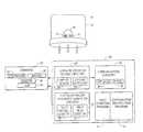
- FIG. 1is a schematic view of a photocontroller including the luminaire diagnostic and configuration and identification system of the subject invention
- FIG. 2is a block diagram showing the primary components associated with the photocontroller shown in FIG. 1 ;
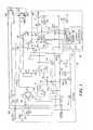
- FIG. 3is a wiring diagram showing the primary components associated with the photocontroller shown in FIG. 1 ;
- FIG. 4is a flow chart depicting the basic steps performed by the microprocessor of the photocontroller shown in FIG. 1 during factory testing;
- FIG. 5is a more detailed flow chart showing the programming associated with the microprocessor of the photocontroller shown in FIG. 1 to detect two possible fault conditions;
- FIG. 6is a flow chart depicting the routine for detecting a cycling event in accordance with the subject invention.
- FIG. 7is a flow chart showing the routine for detecting a lamp out condition in accordance with the subject invention.
- FIG. 8is a flow chart depicting the routine for detecting a photocontroller fault in accordance with the subject invention.
- FIG. 9is a schematic view showing one method of externally transmitting fault conditions in accordance with the subject invention.
- FIG. 10is a schematic view showing another method of externally transmitting fault conditions in accordance with the subject invention.
- Photocontrol device 10FIG. 1 includes thermoplastic, high impact resistant, ultraviolet stabilized polypropylene cover 12 and clear window 14 made from UV stabilized, UV absorbing acrylic for the light sensor which resides on a circuit board within cover 12 .
- Photocontrol device 10is typically configured to fit an ANSI C136.10 receptacle but may be mounted in an ANSI C136.24 “button” package or other enclosure.
- Photocontroller 10is typically mounted on a street light at the top of a light pole. Photocontroller 10 may also be used, however, in conjunction with other types of luminaries and other devices such as golf course water fountains and billboards.
- the circuit board within cover 12is configured to operate in accordance with the block diagram shown in FIG. 2 and , in one example, the specific circuit diagram shown in FIG. 3 .
- Microcontroller 54 shown in the circuit diagram of FIG. 3is programmed in accordance with the flow charts shown in FIGS. 4-8 in accordance with this invention, and transmitter 80 shown in the circuit diagram of FIG. 3 can be linked to a communications network or networks as shown in FIGS. 9 and 10 in accordance with this invention.
- a standard street light type luminaire 20typically includes a controller such as controller 10 , FIG. 1 , ballast 22 , starter or igniter 24 , and a HPS or other type of lamp 26 .
- Lamp 26is more generally referred to as an electrical device or load.
- Microcontroller 54 , FIG. 3includes fault condition detection programing such as photocontroller diagnostic subsystem circuitry 27 , FIG. 2 and luminaire condition sensing circuitry 28 in accordance with this invention which may be integral with photocontroller 10 , FIG. 1 .
- Photocontroller diagnostic subsystem circuitry 27 , FIG. 2includes faulty photocell detector 29 and faulty relay detector 31 .
- Luminaire condition sensing circuitry 28includes lamp out sensor circuitry 30 and cycling detector circuitry 32 .
- faulty photocell detector 29 , faulty relay detector 31 , lamp out sensor circuitry 30 , and cycling detector circuitry 32all uniquely share the same electronic components discussed with reference to FIG. 3 .
- Faulty photocell detector 29 and faulty relay detector 31operate, in the preferred embodiment, as means for verifying the operability of the relay of the photocontroller and also the operability of the light sensor, typically a photocell, of the photocontroller. There are also means for sensing a condition of luminaire 20 such as a lamp out condition or a cycling condition, namely luminaire condition sensing circuitry 28 .
- the microprocessorcan detect a faulty photocell, a faulty relay, a lamp out condition, and a lamp cycling condition. In each case when such a fault is detected, an indication is provided via communication circuitry 34 off site or onsite as shown at 38 , to, for example, illuminate LEDs 13 and/or 15 , FIG. 1 .
- microprocessor 54 , FIG. 3is programmed to detect a cycling event via cycling detection circuitry 32 , FIG. 2 according to one of three possible embodiments or configurations. For example, some customers want the light to turn off immediately upon the detection of a cycling fault and the LED resident on the photocontroller to flash. This programming option is called “option A”, 195 , FIG. 6 , as discussed in the Background section above. Other customers, when a cycling fault is detected, want the light to remain on even in the daytime so it can be readily seen by repair personnel. This “cycling day burner” option is programmed in the microprocessor as “option B”, 196 , FIG. 6 . Still other customers, when a cycling fault is detected, ask that the light be turned off and kept off always thereafter. This is “option C” programming, 197 , FIG. 6 .
- microprocessor 54also includes fault condition programming 41 , FIG. 2 which detects a fault condition based on the load drawn by the lamp (detected by transformer 50 , FIG. 3 ) and configuration identification program 43 , FIG. 2 which provides an indication of a fault according to one of the above configurations (or others).
- microprocessor 54 , FIG. 3is also programmed to output a signal indicative of a no-fault detected condition and in a way that conveys to the quality assurance inspector the configuration of the particular microprocessor on board the photocontroller.
- LED 13flashes the Morse code for the letter configuration programming option A, B, or C discussed above with reference to FIG. 6 .
- transmitter meanssuch as communication circuitry 34 which may include off-site remote communications subsystem 36 and/or on-site communications subsystem 38 which may simply be visual indicator means such as LED 13 , FIG. 1 of one color for indicating the occurrence of a cycling condition or a faulty photocell condition and LED 15 of another color for indicating the occurrence of a lamp out condition or a faulty relay condition.
- the LED'smay also be made to flash to indicate a faulty photocontroller and be steady on to indicate a cycling or lamp out condition
- one of the LEDsduring final product testing, flashes the Morse code for the letter configuration programming option A, B, or C when no fault is detected at final product testing. If the LEDs do not flash at all, a fault of some type is present as discussed infra.
- Off-site communication circuitry 36may also be implemented to transmit these and other conditions to a remote location for real time diagnostics as discussed infra.
- luminaire diagnostic system 40FIG. 2 which includes condition sensing circuitry 28 , diagnostic circuitry 27 , fault condition program 41 , configuration identification program 43 , and communication circuitry 34 eliminates the guess work involved, especially in the day time, when repair personnel attempt to determine which street light and/or a photocontroller has a faulty component.
- the cost of servicing streetlightsis severely reduced in part because the guess work of on-site diagnoses of problems with the street light systems is eliminated.
- Photocontroller diagnostic subsystem circuitry 27includes means for detecting the load drawn by the lamp such as transformer 50 , FIG. 3 coupled to load line 51 and connected to microprocessor 54 via line 56 .
- a hall effect sensorcould also be used as it is functionally equivalent to transformer 50 .
- Diode 58is located on line 56 to rectify the current from transformer 50 .
- Resistor 60 , capacitor 62 , and Zener diode 64are connected across line 56 and neutral line 66 to filter and stabilize the current.
- Capacitor 62filters the rectified AC current present on line 56 and typically has a value of 10 ⁇ F.
- Resistor 60has a typical value of 100 k ⁇ and acts as a bleeder for capacitor 62 .
- Zener diode 64acts to limit the voltage to microprocessor 54 and has a typical value of 4.7 volts at one Watt.
- Microprocessor 54then transmits signals over lines 70 and 72 through resistors 74 and 76 which limit the current output current (typical values are 4.7 k ⁇ ) to LEDs 13 and 15 , respectively.
- transmitter 80may be connected to microprocessor 54 and used to transmit signals indicative of photocontroller and/or lamp conditions sensed by photocontroller diagnostic circuitry and sensing circuitry 28 to a remote location as discussed infra via RF communications. Alternatively, such communication signals may be placed back on the power line to which the lamp is connected via power line carrier electronics package 82 .
- Microprocessor 54is preferably an 18 pin microprocessor part no. PIC16C710 or an eight pin PIC12C671 with an analog to digital converter capability available from Microchip.
- Regulator 118receives this 8 volt VDC signal and maintains a constant 5 volt DC signal to microprocessor 54 .
- the voltage level on pin 1 , 122 of microprocessor 54will vary inversely with the light level.
- the light levelis high (daylight) the voltage is low and when the light level is low (night time) the voltage is high.
- Program variables in the programming of microprocessor 54make it possible to select what light level will turn on switch 126 which in turn energizes relay 106 and also the light level which will turn off switch 126 which in turn de-energizes relay 106 .
- Microprocessor 54FIG. 3 is programmed according to fault condition program 41 , FIG. 2 to begin fault detection, step 300 , FIG. 4 and end fault detection, step 302 , and then only if no fault is detected, step 304 , is configuration identification program 43 , FIG. 2 invoked whereupon the identity of the programming of cycling detector 32 , FIG. 2 is read, step 306 , FIG. 4 and a signal output is provided, step 308 , to, for example, cause LED 13 , FIG. 1 to blink the Morse code for the letter configuration of the cycling detector program as discussed above. Programming then proceeds to FIG. 6 , 7 , and/or 8 as discussed below.
- Fault condition program 41operates when power is first supplied to lamp 26 , FIG. 2 , step 310 , FIG. 5 . This can be accomplished by plugging photocontrol 10 , FIG. 1 into a test lamp fixture for final testing before shipment.
- the load detected by transformer 50 , FIG. 3is then read by microprocessor 54 , step 312 , FIG. 5 .
- the fault condition program 41 , FIG. 2determines whether the load is greater than a predetermined threshold (e.g., 0.5 amps), step 314 , FIG. 5 . If the load is not greater than this threshold, a fault condition is present as shown at step 316 (see also steps 304 and 305 , FIG. 4 ).
- a predetermined thresholde.g., 0.5 amps
- fault condition program 41FIG. 2 resident on microprocessor 54 , FIG. 3 in conjunction with transformer 50 reads the load on the lamp, step 320 , FIG. 5 .
- step 322If the load is less than a predetermined threshold or is preferably zero amps, step 322 , no fault is detected, step 324 whereupon steps 306 and 308 , FIG. 4 are carried out. If the load is not zero amps, a fault is detected as shown at step 326 and no output signal is provided again providing quality assurance personnel and also a lineman with a positive indication that current transformer 50 , FIG. 3 is faulty, ballast 22 , FIG. 2 is open, lamp 26 is defective, starting aid 24 is defective, power is not being supplied to luminaire 20 and/or photocontroller is faulty. Again, corrective action is then taken.
- microprocessor 54FIG. 3 is programmed to output the Morse code signal indicative of the indication configuration only when both the load drawn by the lamp is greater than a predetermined threshold when the lamp is on and also is less than a predetermined threshold when the lamp is off.
- step 306 , FIG. 4the indication configuration (A, B, or C—See 195 , 196 , and 197 , FIG. 6 ) is read, and LED 13 , FIG. 1 flashes the Morse code for the appropriate letter configuration.
- Microprocessor 54also predicts a lamp out and/or lamp cycling condition in accordance with the programming described with reference to FIGS. 6 and 7 and predicts a faulty photocontroller relay and/or a faulty photocontroller photocell in accordance with the programming described with reference to FIG. 8 .
- Microprocessor 54includes the cycling detection routine shown in FIG. 6 wherein the count representing the number of cycles is set to a number such as five upon initialization, step 180 , and then the voltage on line 56 , FIG. 3 , is read periodically at a time t such as every second, step 182 , FIG. 6 . If a subsequent voltage reading is greater than a previous voltage reading, step 184 , the subsequent voltage reading is stored and used as the base line, step 186 . This voltage level is stored in a buffer as a bench mark so that any transients and any voltage levels read during the warm up period will be accounted for.
- Processingthen continues until a subsequent voltage reading is lower than a previous voltage reading, step 188 , by some predetermined threshold, for example, 25%, which indicates the presence of a cycling event.
- the 25% thresholdcould be as low as 12%, but a 12% variation could also be indicative of a power surge and so the 25% threshold is preferred.
- the countis then decremented, step 190 , and once the count reaches some predetermined minimum, step 192 , for example, 0, the fact that a cycling event has occurred is communicated, step 194 , in a fashion similar to the actions taken after step 158 , FIG. 7 .
- the lampcan be turned off permanently or the microprocessor can be programmed to turn the lamp off only for one night and then re-set to again detect cycling the next night to prevent erroneous cycling detection events.
- LEDs 13 or 15 , FIG. 1can be made to flash, and/or a signal can be sent via transmitter 80 to a remote location to indicate the occurrence of a cycling event. An audible alarm could also be used.
- the communication configurations as shown in FIG. 6include option A, 195 ; option B, 196 ; option C, 197 and also possibly option D, 198 and other options as discussed above.
- each microprocessoris internally identified by one of these codes which is read in step 306 , FIG. 4 in order to output a signal indicative of the specific configuration at step 308 either at the factory or during testing by a lineman.
- a lamp out detection routinebegins by reading the voltage level on line 56 , FIG. 3 at some time t 1 after the lamp is first turned on, step 150 , FIG. 7.
- t 1is typically about 2 seconds which is sufficient time to eliminate any transients in the circuitry.
- t 2typically 3 minutes, the voltage is again read, step 152 , and these two voltages are compared to determine whether they are lower than a preset threshold, step 154 , typically about 12.5 percent. If the difference between the two different voltage level readings is greater than this threshold, processing transfers to the cycle detection mode discussed with reference to FIG. 6 . If, however, on the other hand, the difference between the two different voltage readings is less than this threshold, this is indicative of a lamp out condition, step 156 , FIG. 7 .
- microprocessor 54determines a lamp out condition, step 156 , FIG. 7 , it can take any number of lamp out condition actions, step 158 , such as energizing LED 15 , FIGS. 1 and 3 , step 160 , FIG. 7 , provide a signal to transmitter 80 , FIG. 3 to communicate to a remote base station, step 162 , FIG.
- Receiver 81 , FIG. 3may be used as a means to activate certain routines programmed in microprocessor 54 , FIG. 3 including a routine to power the lamp in daylight hours for daytime testing.
- the photocontroller diagnostic section 27 , FIG. 2 of the programis written to allow detection of photocontroller component failures.
- the operability of two components that the program can detectare typically photocell 120 , FIG. 3 and relay 106 .
- a faulty relay conditionis defined as the current being drawn by the lamp during a certain ambient light condition, typically daylight or a day. In other cases, such as for golf course water fountains, the ambient light condition is night.
- a faulty photocell conditionis defined by twenty-four hours of continuous daytime and nighttime lamp operation.
- initialization step 130When power is first applied to the photocontroller, initialization step 130 , FIG. 8 sets all counters. The light level is then read every 0.5 seconds in step 131 . The light level read is compared to a predetermined level and a decision is made whether it is light or dark, step 132 . If it is light, the next question is whether a fault has already been detected, step 133 . If so, the program will go back and check light level again. If no fault has previously been detected, then the program will wait two-seconds, step 134 , and then read the current, step 135 . The program will then check to see if there is a current draw, step 136 . If no current is drawn, then the relay is properly operating since there should be no current drawn during daylight hours.
- step 137the program will call the hour counter, step 137 . If current is drawn, then there is a problem and one second is subtracted from the counter, step 138 and a check is made to see if hour counter is at zero, step 139 . If the hour count is not zero, then the program proceeds to step 137 to call the hour counter. If the hour count is zero, then the relay is faulty, a condition which is communicated via a relay fault signal, step 140 to LED's 13 and/or 15 , FIG. 1 . In addition, or alternatively, the relay fault signal could be transmitted to a remote location as discussed with reference to FIGS. 6-7 .
- step 132the program would next determine if it was a new night, step 141 . If it is a new night, then all faults and counter and timers are reset, step 142 . The program then goes on to check the light level again step 131 .
- step 137the hour counter is called. This hour counter is used to count the length of the night or day. If in step 143 it is determined that the hour counter is equal to a preset threshold, e.g., twenty-four hours, then the photocell is faulty. The program then communicates this fault, step 140 and causes LEDs 13 and/or 15 , FIG. 1 , to energize. Again, this faulty photocell signal could also or alternatively be communicated to a remote location as discussed below with reference to FIGS. 6-7 . If the hour counter in step 143 , FIG. 8 is not equal to twenty-four hours, then the light level is checked again, step 131 .
- a preset thresholde.g., twenty-four hours
- External communicationsmay occur via RF transmission or via powerline carrier technology as shown in FIG. 9 from street light 200 to street light 202 to street light, whereupon the condition information is sent to final or intermediate base station 204 and, if required, to other base stations or other locations as shown at 206 in any number of ways including satellite transmission, RF transmissions, land line transmissions, and the like.
- a communication networkutilizing RF transmitters and/or transmitter receivers can be used wherein one set of transmitters resident on the photocontrollers described above transit to communication control unit 210 which in turn communicates to network control node 212 which also receives communications from communication control unit 214 .
- Network control node 212then communicates with central base station 216 as is known in the art of remote meter reading technology. In this way, information regarding the operability of the photocontroller (faulty relay, faulty photocell) and/or the luminaire (a cycling condition, faulty lamp) can be transmitted to remote locations for real time diagnostics.
- LEDs 13 and 15can be the only indicators in an less expensive, less complex photocontroller in accordance with the subject invention.
- other types of visual and even non-visual alarm indicatorscould be used instead of LEDs 13 and 15 .
- additional LEDscould be used such that one signals the occurrence of a faulty relay, one signals the presence of a faulty photocell, one signals the presence of a cycling condition, and one signals a faulty lamp condition.
- One LEDalso outputs the Morse code of the microprocessor's programming configuration as discussed with reference to FIGS. 4-5 when no fault is detected at the factory or on the lamp pole.
- photocontroller 10includes sensor 120 , FIG. 3 which, in combination with microprocessor 54 and the circuitry shown in FIG. 3 determines the presence of daylight.
- Relay meanssuch as relay 106 is responsive to sensor 120 via microprocessor 54 , de-energizes luminaire 20 , FIG. 2 during periods of daylight and energizes lamp 20 during periods of darkness.
- microprocessor 54is programmed to turn the fountain on during the day and off at night.
- the relay meanscould also be a TRIAC, FET or other sold state device.
- the diagnostic subsystem of this inventionincludes two primary components: a photocontroller diagnostic routine and a luminaire diagnostic route.
- Microprocessor 54 , FIG. 3is programmed in accordance with steps 130 - 143 , FIG. 8 to verify the operability of relay 106 , FIG. 3 and sensor 120 , (typically a photocell), and to then transmit a signal representing a failure of either component.
- a faulty relayis usually detected by determining whether current is drawn by the lamp during daylight hours.
- a faulty photocellis usually detected by determining whether the lamp remains on or off for a preestablished time period, e.g., 24 hours.
- the luminaire diagnostic routineoperates in accordance with the processing steps shown in FIGS. 6 and 7 .
- Transformer 50FIG. 3 is used, in combination with microprocessor 54 to detect the load drawn by the lamp. This information is used both by the photocontroller diagnostic routine and the luminaire diagnostic routine.
- the subject inventionalso provides a luminaire diagnostic and configuration identification system as discussed with reference to FIGS. 2 and 4 - 5 .
- a luminaire diagnostic and configuration identification systemas discussed with reference to FIGS. 2 and 4 - 5 .
- Such a systemis easier and faster to inspect.
- Microprocessor 54 , FIG. 3is programmed according to the flowcharts of FIGS. 4 and 5 to output a positive indication when no fault is detected in the photocontrol in a manner that provides a positive indication to quality assurance personnel regarding the particular microprocessor configuration resident in the photocontroller (e.g., programming options A, B, or C as shown in FIG. 6 ).
- FIGS. 1-2can be effected by programming microprocessor 54 , FIG. 3 of the photocontrol to quickly detect a fault condition based on the load drawn by the lamp and then to provide a positive indication when no fault is detected in a way that also informs quality assurance personnel which fault indication program version is resident on the microprocessor of the photocontrol as shown at 41 and 43 , FIG. 2 and in FIGS. 4-5 .
- microprocessor 54FIG. 3 could be located in a unit which plugs into the lamp fixture much like a standard photocontrol and then the photocontrol shown in FIG. 1 plugs into that unit.
- Exemplary programming code for fault condition program 41 , FIG. 2 and configuration identification program 43is attached hereto as appendix A.
Landscapes
- Circuit Arrangement For Electric Light Sources In General (AREA)
- Testing Of Short-Circuits, Discontinuities, Leakage, Or Incorrect Line Connections (AREA)
Abstract
Description
Claims (49)
Priority Applications (1)
| Application Number | Priority Date | Filing Date | Title |
|---|---|---|---|
| US10/362,823US6841944B2 (en) | 2000-08-22 | 2001-08-22 | Luminaire diagnostic and configuration identification system |
Applications Claiming Priority (3)
| Application Number | Priority Date | Filing Date | Title |
|---|---|---|---|
| US22708900P | 2000-08-22 | 2000-08-22 | |
| US10/362,823US6841944B2 (en) | 2000-08-22 | 2001-08-22 | Luminaire diagnostic and configuration identification system |
| PCT/US2001/026271WO2002017691A1 (en) | 2000-08-22 | 2001-08-22 | Luminaire diagnostic and configuration identification system |
Publications (2)
| Publication Number | Publication Date |
|---|---|
| US20040124786A1 US20040124786A1 (en) | 2004-07-01 |
| US6841944B2true US6841944B2 (en) | 2005-01-11 |
Family
ID=22851704
Family Applications (1)
| Application Number | Title | Priority Date | Filing Date |
|---|---|---|---|
| US10/362,823Expired - LifetimeUS6841944B2 (en) | 2000-08-22 | 2001-08-22 | Luminaire diagnostic and configuration identification system |
Country Status (6)
| Country | Link |
|---|---|
| US (1) | US6841944B2 (en) |
| AU (1) | AU2001285208A1 (en) |
| CA (1) | CA2420237C (en) |
| GB (1) | GB2381395B (en) |
| MX (1) | MXPA03001561A (en) |
| WO (1) | WO2002017691A1 (en) |
Cited By (33)
| Publication number | Priority date | Publication date | Assignee | Title |
|---|---|---|---|---|
| US20050035720A1 (en)* | 2003-08-07 | 2005-02-17 | Blake Frederick H. | Anti-cycling control system for luminaires |
| US20060091822A1 (en)* | 2004-11-04 | 2006-05-04 | Rensselaer Polytechnic Institute | Self-commissioning daylight switching system |
| US20060197523A1 (en)* | 2005-03-04 | 2006-09-07 | Assurance Technology Corporation | Magnetic screening system |
| US20070057807A1 (en)* | 2005-09-12 | 2007-03-15 | Acuity Brands, Inc. | Activation device for an intelligent luminaire manager |
| US20090001893A1 (en)* | 2005-06-30 | 2009-01-01 | Streetlight Intelligence, Inc. | Method and system for luminance characterization |
| US20090066540A1 (en)* | 2007-09-07 | 2009-03-12 | Dimitri Marinakis | Centralized route calculation for a multi-hop streetlight network |
| US20090066258A1 (en)* | 2007-09-07 | 2009-03-12 | Streetlight Intelligence, Inc. | Streelight monitoring and control |
| US7817063B2 (en) | 2005-10-05 | 2010-10-19 | Abl Ip Holding Llc | Method and system for remotely monitoring and controlling field devices with a street lamp elevated mesh network |
| US20100289412A1 (en)* | 2009-05-04 | 2010-11-18 | Stuart Middleton-White | Integrated lighting system and method |
| US20100295482A1 (en)* | 2009-04-14 | 2010-11-25 | Digital Lumens, Inc. | Power Management Unit with Multi-Input Arbitration |
| US20100295473A1 (en)* | 2008-04-14 | 2010-11-25 | Digital Lumens, Inc. | Power Management Unit with Sensor Logging |
| US20100301774A1 (en)* | 2008-04-14 | 2010-12-02 | Digital Lumens, Inc. | Power Management Unit with Automatic Output Configuration |
| US20100301771A1 (en)* | 2008-04-14 | 2010-12-02 | Digital Lumens, Inc. | Power Management Unit with Power Source Arbitration |
| US20110001436A1 (en)* | 2008-04-14 | 2011-01-06 | Digital Lumens, Inc. | Power Management Unit with Light Module Identification |
| US20110260624A1 (en)* | 2010-04-27 | 2011-10-27 | Cooper Technologies Company | Lighting System Having Photocontrol and Fault Monitoring Capabilities |
| US8140276B2 (en) | 2008-02-27 | 2012-03-20 | Abl Ip Holding Llc | System and method for streetlight monitoring diagnostics |
| US8433426B2 (en) | 2005-06-30 | 2013-04-30 | Led Roadway Lighting Ltd | Adaptive energy performance monitoring and control system |
| US8884532B2 (en) | 2012-05-25 | 2014-11-11 | Ripley Lighting Controls, LLC | Photo control for a luminaire |
| US9014829B2 (en) | 2010-11-04 | 2015-04-21 | Digital Lumens, Inc. | Method, apparatus, and system for occupancy sensing |
| US9072133B2 (en) | 2008-04-14 | 2015-06-30 | Digital Lumens, Inc. | Lighting fixtures and methods of commissioning lighting fixtures |
| US9241392B2 (en) | 2012-03-19 | 2016-01-19 | Digital Lumens, Inc. | Methods, systems, and apparatus for providing variable illumination |
| US9510426B2 (en) | 2011-11-03 | 2016-11-29 | Digital Lumens, Inc. | Methods, systems, and apparatus for intelligent lighting |
| US9693428B2 (en) | 2014-10-15 | 2017-06-27 | Abl Ip Holding Llc | Lighting control with automated activation process |
| US9781814B2 (en) | 2014-10-15 | 2017-10-03 | Abl Ip Holding Llc | Lighting control with integral dimming |
| US9924576B2 (en) | 2013-04-30 | 2018-03-20 | Digital Lumens, Inc. | Methods, apparatuses, and systems for operating light emitting diodes at low temperature |
| US10230634B2 (en) | 2015-09-25 | 2019-03-12 | Osram Sylvania Inc. | Route optimization using star-mesh hybrid topology in localized dense ad-hoc networks |
| US10264652B2 (en) | 2013-10-10 | 2019-04-16 | Digital Lumens, Inc. | Methods, systems, and apparatus for intelligent lighting |
| US10485068B2 (en) | 2008-04-14 | 2019-11-19 | Digital Lumens, Inc. | Methods, apparatus, and systems for providing occupancy-based variable lighting |
| US10499487B2 (en) | 2015-10-05 | 2019-12-03 | Scalia Lighting Technologies LLC | Light-emitting diode (LED) lighting fixture solutions and methods |
| US10564613B2 (en) | 2010-11-19 | 2020-02-18 | Hubbell Incorporated | Control system and method for managing wireless and wired components |
| US10891881B2 (en) | 2012-07-30 | 2021-01-12 | Ultravision Technologies, Llc | Lighting assembly with LEDs and optical elements |
| US11959631B2 (en) | 2007-12-21 | 2024-04-16 | Appalachian Lighting Systems, Inc. | Lighting fixture |
| US12231337B2 (en) | 2015-09-25 | 2025-02-18 | Digital Lumens Incorporated | Route optimization using star-mesh hybrid topology in localized dense ad-hoc networks |
Families Citing this family (10)
| Publication number | Priority date | Publication date | Assignee | Title |
|---|---|---|---|---|
| EP1699272A1 (en)* | 2005-03-02 | 2006-09-06 | Noontek Limited | A public lighting assembly with ambient light detection means and transceiver |
| EP1698826A1 (en)* | 2005-03-02 | 2006-09-06 | Noontek Limited | A street lamp assembly |
| FR2899035B1 (en)* | 2006-03-22 | 2009-06-12 | Lyracom Sarl | AUTONOMOUS UNIT FOR A MEASUREMENT SENSOR NETWORK, NETWORK INCORPORATING SAME AUTONOMOUS UNIT AND COMMUNICATION PROTOCOL OF SAID NETWORK |
| FR2925653B1 (en)* | 2007-12-20 | 2010-03-26 | Beg France | SECURE LIGHTING MANAGEMENT SYSTEM |
| US8680969B2 (en)* | 2009-03-20 | 2014-03-25 | Lutron Electronics Co., Inc. | Method of confirming that a control device complies with a predefined protocol standard |
| US8864514B2 (en) | 2010-10-07 | 2014-10-21 | General Electric Company | Controller device |
| TWI576111B (en) | 2011-02-25 | 2017-04-01 | 久光製藥股份有限公司 | Adjuvant for transdermal or transmucosal administration and pharmaceutical preparation contaning the same |
| US8901825B2 (en)* | 2011-04-12 | 2014-12-02 | Express Imaging Systems, Llc | Apparatus and method of energy efficient illumination using received signals |
| US9398662B2 (en)* | 2014-09-23 | 2016-07-19 | Lucis Technologies Holdings Limited | LED control system |
| US10009983B2 (en)* | 2015-06-24 | 2018-06-26 | Abl Ip Holding Llc | Networking groups of photocontrol devices |
Citations (10)
| Publication number | Priority date | Publication date | Assignee | Title |
|---|---|---|---|---|
| US5103137A (en) | 1990-04-02 | 1992-04-07 | Multipoint Control Systems, Inc. | Anti-cycling device for high pressure sodium lamps |
| US5235252A (en) | 1991-12-31 | 1993-08-10 | Blake Frederick H | Fiber-optic anti-cycling device for street lamps |
| US5828178A (en) | 1996-12-09 | 1998-10-27 | Tir Systems Ltd. | High intensity discharge lamp color |
| US5895986A (en)* | 1997-04-30 | 1999-04-20 | Walters; Jeff D. | Photoelectric load control system and method |
| US6028396A (en)* | 1997-08-19 | 2000-02-22 | Dark To Light | Luminaire diagnostic system |
| US6087776A (en)* | 1997-01-14 | 2000-07-11 | Koito Manufacturing Co., Ltd. | Discharge lamp lighting circuit with protection circuit |
| US6452340B1 (en) | 1999-04-09 | 2002-09-17 | Acuity Brands, Inc. | Luminaire starting aid device |
| US6452339B1 (en)* | 1997-08-19 | 2002-09-17 | Acuity Brands, Inc. | Photocontroller diagnostic system |
| US6495973B1 (en)* | 2001-07-17 | 2002-12-17 | Charles W. Allen, Jr. | Lighting control system and method |
| US6542340B1 (en)* | 1999-09-01 | 2003-04-01 | Nec Corporation | Magnetoresistance element, manufacturing method thereof, magnetic field detection system and magnetic recording system |
- 2001
- 2001-08-22USUS10/362,823patent/US6841944B2/ennot_activeExpired - Lifetime
- 2001-08-22WOPCT/US2001/026271patent/WO2002017691A1/enactiveApplication Filing
- 2001-08-22MXMXPA03001561Apatent/MXPA03001561A/enactiveIP Right Grant
- 2001-08-22AUAU2001285208Apatent/AU2001285208A1/ennot_activeAbandoned
- 2001-08-22GBGB0303845Apatent/GB2381395B/ennot_activeExpired - Lifetime
- 2001-08-22CACA2420237Apatent/CA2420237C/ennot_activeExpired - Lifetime
Patent Citations (10)
| Publication number | Priority date | Publication date | Assignee | Title |
|---|---|---|---|---|
| US5103137A (en) | 1990-04-02 | 1992-04-07 | Multipoint Control Systems, Inc. | Anti-cycling device for high pressure sodium lamps |
| US5235252A (en) | 1991-12-31 | 1993-08-10 | Blake Frederick H | Fiber-optic anti-cycling device for street lamps |
| US5828178A (en) | 1996-12-09 | 1998-10-27 | Tir Systems Ltd. | High intensity discharge lamp color |
| US6087776A (en)* | 1997-01-14 | 2000-07-11 | Koito Manufacturing Co., Ltd. | Discharge lamp lighting circuit with protection circuit |
| US5895986A (en)* | 1997-04-30 | 1999-04-20 | Walters; Jeff D. | Photoelectric load control system and method |
| US6028396A (en)* | 1997-08-19 | 2000-02-22 | Dark To Light | Luminaire diagnostic system |
| US6452339B1 (en)* | 1997-08-19 | 2002-09-17 | Acuity Brands, Inc. | Photocontroller diagnostic system |
| US6452340B1 (en) | 1999-04-09 | 2002-09-17 | Acuity Brands, Inc. | Luminaire starting aid device |
| US6542340B1 (en)* | 1999-09-01 | 2003-04-01 | Nec Corporation | Magnetoresistance element, manufacturing method thereof, magnetic field detection system and magnetic recording system |
| US6495973B1 (en)* | 2001-07-17 | 2002-12-17 | Charles W. Allen, Jr. | Lighting control system and method |
Non-Patent Citations (1)
| Title |
|---|
| International Search Report in related PCT/US01/26271 (Nov. 16, 2001). |
Cited By (84)
| Publication number | Priority date | Publication date | Assignee | Title |
|---|---|---|---|---|
| US20050035720A1 (en)* | 2003-08-07 | 2005-02-17 | Blake Frederick H. | Anti-cycling control system for luminaires |
| US7323826B2 (en)* | 2003-08-07 | 2008-01-29 | Blake Frederick H | Anti-cycling control system for luminaires |
| US20060091822A1 (en)* | 2004-11-04 | 2006-05-04 | Rensselaer Polytechnic Institute | Self-commissioning daylight switching system |
| US7045968B1 (en)* | 2004-11-04 | 2006-05-16 | Rensselaer Polytechnic Institute | Self-commissioning daylight switching system |
| US7898248B2 (en) | 2005-03-04 | 2011-03-01 | Assurance Technology Corporation | Magnetic screening system and a network managing same |
| US20090327191A1 (en)* | 2005-03-04 | 2009-12-31 | Assurance Technology Corporation | Magnetic screening system network |
| US20060197523A1 (en)* | 2005-03-04 | 2006-09-07 | Assurance Technology Corporation | Magnetic screening system |
| US20110057570A1 (en)* | 2005-06-30 | 2011-03-10 | Streetlight Intelligence, Inc. | Method and System for Luminance Characterization |
| US8433426B2 (en) | 2005-06-30 | 2013-04-30 | Led Roadway Lighting Ltd | Adaptive energy performance monitoring and control system |
| US8264156B2 (en) | 2005-06-30 | 2012-09-11 | Led Roadway Lighting Ltd. | Method and system for luminance characterization |
| US9144135B2 (en) | 2005-06-30 | 2015-09-22 | Led Roadway Lighting Ltd. | Adaptive energy performance monitoring and control system |
| US7834555B2 (en)* | 2005-06-30 | 2010-11-16 | Streetlight Intelligence, Inc. | Method and system for luminance characterization |
| US20090001893A1 (en)* | 2005-06-30 | 2009-01-01 | Streetlight Intelligence, Inc. | Method and system for luminance characterization |
| US7603184B2 (en) | 2005-09-12 | 2009-10-13 | Abl Ip Holding Llc | Light management system having networked intelligent luminaire managers |
| US20100287081A1 (en)* | 2005-09-12 | 2010-11-11 | Abl Ip Holding Llc | Light management system having networked intelligent luminaire managers |
| US7529594B2 (en)* | 2005-09-12 | 2009-05-05 | Abl Ip Holding Llc | Activation device for an intelligent luminaire manager |
| US7546168B2 (en) | 2005-09-12 | 2009-06-09 | Abl Ip Holding Llc | Owner/operator control of a light management system using networked intelligent luminaire managers |
| US7546167B2 (en) | 2005-09-12 | 2009-06-09 | Abl Ip Holdings Llc | Network operation center for a light management system having networked intelligent luminaire managers |
| US8260575B2 (en) | 2005-09-12 | 2012-09-04 | Abl Ip Holding Llc | Light management system having networked intelligent luminaire managers |
| US20070057807A1 (en)* | 2005-09-12 | 2007-03-15 | Acuity Brands, Inc. | Activation device for an intelligent luminaire manager |
| US7761260B2 (en) | 2005-09-12 | 2010-07-20 | Abl Ip Holding Llc | Light management system having networked intelligent luminaire managers with enhanced diagnostics capabilities |
| US20070085702A1 (en)* | 2005-09-12 | 2007-04-19 | Acuity Brands, Inc. | Light management system having networked intelligent luminaire managers |
| US20070085701A1 (en)* | 2005-09-12 | 2007-04-19 | Acuity Brands, Inc. | Light management system having networked intelligent luminaire managers that support third-party applications |
| US7333903B2 (en)* | 2005-09-12 | 2008-02-19 | Acuity Brands, Inc. | Light management system having networked intelligent luminaire managers with enhanced diagnostics capabilities |
| US8010319B2 (en) | 2005-09-12 | 2011-08-30 | Abl Ip Holding Llc | Light management system having networked intelligent luminaire managers |
| US20070091623A1 (en)* | 2005-09-12 | 2007-04-26 | Acuity Brands, Inc. | Owner/operator control of a light management system using networked intelligent luminaire managers |
| US7911359B2 (en) | 2005-09-12 | 2011-03-22 | Abl Ip Holding Llc | Light management system having networked intelligent luminaire managers that support third-party applications |
| US20070085699A1 (en)* | 2005-09-12 | 2007-04-19 | Acuity Brands, Inc. | Network operation center for a light management system having networked intelligent luminaire managers |
| US20070085700A1 (en)* | 2005-09-12 | 2007-04-19 | Acuity Brands, Inc. | Light management system having networked intelligent luminaire managers with enhanced diagnostics capabilities |
| US7817063B2 (en) | 2005-10-05 | 2010-10-19 | Abl Ip Holding Llc | Method and system for remotely monitoring and controlling field devices with a street lamp elevated mesh network |
| US20090066540A1 (en)* | 2007-09-07 | 2009-03-12 | Dimitri Marinakis | Centralized route calculation for a multi-hop streetlight network |
| US8570190B2 (en) | 2007-09-07 | 2013-10-29 | Led Roadway Lighting Ltd. | Centralized route calculation for a multi-hop streetlight network |
| US8694256B2 (en) | 2007-09-07 | 2014-04-08 | Led Roadway Lighting Ltd. | Streetlight monitoring and control |
| US8290710B2 (en) | 2007-09-07 | 2012-10-16 | Led Roadway Lighting Ltd. | Streetlight monitoring and control |
| US20090066258A1 (en)* | 2007-09-07 | 2009-03-12 | Streetlight Intelligence, Inc. | Streelight monitoring and control |
| US11959631B2 (en) | 2007-12-21 | 2024-04-16 | Appalachian Lighting Systems, Inc. | Lighting fixture |
| US8442785B2 (en) | 2008-02-27 | 2013-05-14 | Abl Ip Holding Llc | System and method for streetlight monitoring diagnostics |
| US8594976B2 (en) | 2008-02-27 | 2013-11-26 | Abl Ip Holding Llc | System and method for streetlight monitoring diagnostics |
| US8140276B2 (en) | 2008-02-27 | 2012-03-20 | Abl Ip Holding Llc | System and method for streetlight monitoring diagnostics |
| US20100295473A1 (en)* | 2008-04-14 | 2010-11-25 | Digital Lumens, Inc. | Power Management Unit with Sensor Logging |
| US8841859B2 (en) | 2008-04-14 | 2014-09-23 | Digital Lumens Incorporated | LED lighting methods, apparatus, and systems including rules-based sensor data logging |
| US10539311B2 (en) | 2008-04-14 | 2020-01-21 | Digital Lumens Incorporated | Sensor-based lighting methods, apparatus, and systems |
| US20100301771A1 (en)* | 2008-04-14 | 2010-12-02 | Digital Lumens, Inc. | Power Management Unit with Power Source Arbitration |
| US20100301774A1 (en)* | 2008-04-14 | 2010-12-02 | Digital Lumens, Inc. | Power Management Unit with Automatic Output Configuration |
| US10485068B2 (en) | 2008-04-14 | 2019-11-19 | Digital Lumens, Inc. | Methods, apparatus, and systems for providing occupancy-based variable lighting |
| US9125254B2 (en) | 2008-04-14 | 2015-09-01 | Digital Lumens, Inc. | Lighting fixtures and methods of commissioning lighting fixtures |
| US8805550B2 (en) | 2008-04-14 | 2014-08-12 | Digital Lumens Incorporated | Power management unit with power source arbitration |
| US8823277B2 (en) | 2008-04-14 | 2014-09-02 | Digital Lumens Incorporated | Methods, systems, and apparatus for mapping a network of lighting fixtures with light module identification |
| US20110001436A1 (en)* | 2008-04-14 | 2011-01-06 | Digital Lumens, Inc. | Power Management Unit with Light Module Identification |
| US8866408B2 (en) | 2008-04-14 | 2014-10-21 | Digital Lumens Incorporated | Methods, apparatus, and systems for automatic power adjustment based on energy demand information |
| US9860961B2 (en) | 2008-04-14 | 2018-01-02 | Digital Lumens Incorporated | Lighting fixtures and methods via a wireless network having a mesh network topology |
| US9072133B2 (en) | 2008-04-14 | 2015-06-30 | Digital Lumens, Inc. | Lighting fixtures and methods of commissioning lighting fixtures |
| US11193652B2 (en) | 2008-04-14 | 2021-12-07 | Digital Lumens Incorporated | Lighting fixtures and methods of commissioning light fixtures |
| US10362658B2 (en) | 2008-04-14 | 2019-07-23 | Digital Lumens Incorporated | Lighting fixtures and methods for automated operation of lighting fixtures via a wireless network having a mesh network topology |
| US8954170B2 (en) | 2009-04-14 | 2015-02-10 | Digital Lumens Incorporated | Power management unit with multi-input arbitration |
| US20100295482A1 (en)* | 2009-04-14 | 2010-11-25 | Digital Lumens, Inc. | Power Management Unit with Multi-Input Arbitration |
| US9055624B2 (en) | 2009-05-04 | 2015-06-09 | Hubbell Incorporated | Integrated lighting system and method |
| US20100289412A1 (en)* | 2009-05-04 | 2010-11-18 | Stuart Middleton-White | Integrated lighting system and method |
| US10212784B2 (en) | 2009-05-04 | 2019-02-19 | Hubbell Incorporated | Integrated lighting system and method |
| US8436542B2 (en) | 2009-05-04 | 2013-05-07 | Hubbell Incorporated | Integrated lighting system and method |
| US10842001B2 (en) | 2009-05-04 | 2020-11-17 | Hubbell Incorporated | Integrated lighting system and method |
| US9832840B2 (en) | 2009-05-04 | 2017-11-28 | Hubbell Incorporated | Integrated lighting system and method |
| US9877373B2 (en) | 2009-05-04 | 2018-01-23 | Hubbell Incorporated | Integrated lighting system and method |
| US8310159B2 (en)* | 2010-04-27 | 2012-11-13 | Cooper Technologies Company | Lighting system having photocontrol and fault monitoring capabilities |
| US20110260624A1 (en)* | 2010-04-27 | 2011-10-27 | Cooper Technologies Company | Lighting System Having Photocontrol and Fault Monitoring Capabilities |
| US9915416B2 (en) | 2010-11-04 | 2018-03-13 | Digital Lumens Inc. | Method, apparatus, and system for occupancy sensing |
| US9014829B2 (en) | 2010-11-04 | 2015-04-21 | Digital Lumens, Inc. | Method, apparatus, and system for occupancy sensing |
| US11934161B2 (en) | 2010-11-19 | 2024-03-19 | HLI Solutions, Inc. | Control system and method for managing wireless and wired components |
| US10564613B2 (en) | 2010-11-19 | 2020-02-18 | Hubbell Incorporated | Control system and method for managing wireless and wired components |
| US11188041B2 (en) | 2010-11-19 | 2021-11-30 | Hubbell Incorporated | Control system and method for managing wireless and wired components |
| US10306733B2 (en) | 2011-11-03 | 2019-05-28 | Digital Lumens, Inc. | Methods, systems, and apparatus for intelligent lighting |
| US9510426B2 (en) | 2011-11-03 | 2016-11-29 | Digital Lumens, Inc. | Methods, systems, and apparatus for intelligent lighting |
| US9241392B2 (en) | 2012-03-19 | 2016-01-19 | Digital Lumens, Inc. | Methods, systems, and apparatus for providing variable illumination |
| US9832832B2 (en) | 2012-03-19 | 2017-11-28 | Digital Lumens, Inc. | Methods, systems, and apparatus for providing variable illumination |
| US8884532B2 (en) | 2012-05-25 | 2014-11-11 | Ripley Lighting Controls, LLC | Photo control for a luminaire |
| US10891881B2 (en) | 2012-07-30 | 2021-01-12 | Ultravision Technologies, Llc | Lighting assembly with LEDs and optical elements |
| US9924576B2 (en) | 2013-04-30 | 2018-03-20 | Digital Lumens, Inc. | Methods, apparatuses, and systems for operating light emitting diodes at low temperature |
| US10264652B2 (en) | 2013-10-10 | 2019-04-16 | Digital Lumens, Inc. | Methods, systems, and apparatus for intelligent lighting |
| US9781814B2 (en) | 2014-10-15 | 2017-10-03 | Abl Ip Holding Llc | Lighting control with integral dimming |
| US9693428B2 (en) | 2014-10-15 | 2017-06-27 | Abl Ip Holding Llc | Lighting control with automated activation process |
| US11575603B2 (en) | 2015-09-25 | 2023-02-07 | Digital Lumens Incorporated | Route optimization using star-mesh hybrid topology in localized dense ad-hoc networks |
| US10230634B2 (en) | 2015-09-25 | 2019-03-12 | Osram Sylvania Inc. | Route optimization using star-mesh hybrid topology in localized dense ad-hoc networks |
| US12231337B2 (en) | 2015-09-25 | 2025-02-18 | Digital Lumens Incorporated | Route optimization using star-mesh hybrid topology in localized dense ad-hoc networks |
| US10499487B2 (en) | 2015-10-05 | 2019-12-03 | Scalia Lighting Technologies LLC | Light-emitting diode (LED) lighting fixture solutions and methods |
Also Published As
| Publication number | Publication date |
|---|---|
| CA2420237A1 (en) | 2002-02-28 |
| WO2002017691A1 (en) | 2002-02-28 |
| AU2001285208A1 (en) | 2002-03-04 |
| GB2381395A (en) | 2003-04-30 |
| GB0303845D0 (en) | 2003-03-26 |
| CA2420237C (en) | 2013-01-22 |
| MXPA03001561A (en) | 2004-12-13 |
| GB2381395B (en) | 2004-09-01 |
| WO2002017691A8 (en) | 2002-03-21 |
| US20040124786A1 (en) | 2004-07-01 |
Similar Documents
| Publication | Publication Date | Title |
|---|---|---|
| US6841944B2 (en) | Luminaire diagnostic and configuration identification system | |
| US6452339B1 (en) | Photocontroller diagnostic system | |
| US6028396A (en) | Luminaire diagnostic system | |
| US6452340B1 (en) | Luminaire starting aid device | |
| US6396216B1 (en) | Lamp fault detection | |
| CA1311800C (en) | Independent emergency lighting system with self-diagnosis | |
| US4580099A (en) | Device for the remote detection of a failed lamp in a lighting system with a plurality of lamps connected in parallel | |
| KR20170110205A (en) | LED type light signal device with separated control component and display component | |
| US5103137A (en) | Anti-cycling device for high pressure sodium lamps | |
| KR101623808B1 (en) | Apparatus of detecting defective street lights | |
| KR200283297Y1 (en) | Device for sensing and displaying the trouble of the streetlamp | |
| GB2380620A (en) | Automatic emergency lamp testing unit | |
| KR20080081390A (en) | Street lamp failure detection device and method | |
| CA2352716A1 (en) | System for testing the presence of an ignitor pulse within a high intensity discharge luminaire | |
| CA2315500C (en) | Photocontroller diagnostic system | |
| GB2287309A (en) | Lighting unit | |
| EP0711498B1 (en) | Microprocessor device for monitoring and controlling light fittings, and method using same | |
| US9578717B2 (en) | Monitoring and control device and method for an illumination apparatus | |
| KR200224410Y1 (en) | Error detector of lighting system using power line | |
| KR20020092280A (en) | Electric-leak location checking device and method by safety voltage | |
| WO2001045472A1 (en) | Lamp state detector and lamp state monitor using lamp state detector | |
| KR100201302B1 (en) | Strange lamp automatic detection apparatus | |
| GB1567506A (en) | Emergency lighting units and installations | |
| KR100639350B1 (en) | Street lamp failure detection device and method | |
| KR100566371B1 (en) | Automatic flashing control device |
Legal Events
| Date | Code | Title | Description |
|---|---|---|---|
| AS | Assignment | Owner name:THOMAS & BETTS INTERNATIONAL, INC., NEVADA Free format text:ASSIGNMENT OF ASSIGNORS INTEREST;ASSIGNORS:MORRISSEY, JOSEPH F.;LIBEN, MARTIN W.;MURPHY, THOMAS;REEL/FRAME:015595/0746;SIGNING DATES FROM 20011001 TO 20011017 Owner name:ACUITY BRANDS, INC., GEORGIA Free format text:CHANGE OF NAME;ASSIGNOR:L&C SPINCO, INC.;REEL/FRAME:015595/0752 Effective date:20011109 Owner name:ACUITY BRANDS, INC., GEORGIA Free format text:ASSIGNMENT OF ASSIGNORS INTEREST;ASSIGNORS:MORRISSEY, JOSEPH F.;LIBEN, MARTIN W.;MURPHY, THOMAS;REEL/FRAME:015595/0763;SIGNING DATES FROM 20020618 TO 20021105 Owner name:L&C SPINCO, INC., GEORGIA Free format text:ASSIGNMENT OF ASSIGNORS INTEREST;ASSIGNORS:THOMAS & BETTS CORPORATION;THOMAS & BETTS INTERNATIONAL, INC.;REEL/FRAME:015593/0459 Effective date:20011012 | |
| STCF | Information on status: patent grant | Free format text:PATENTED CASE | |
| AS | Assignment | Owner name:ACUITY BRANDS, INC., GEORGIA Free format text:ASSIGNMENT OF ASSIGNORS INTEREST;ASSIGNORS:MORRISSEY, JR., JOSEPH F.;LIBEN, MARTIN W.;MURPHY, THOMAS A.;REEL/FRAME:016209/0489 Effective date:20021105 | |
| FPAY | Fee payment | Year of fee payment:4 | |
| AS | Assignment | Owner name:ABL IP HOLDING, LLC, GEORGIA Free format text:ASSIGNMENT OF ASSIGNORS INTEREST;ASSIGNOR:ACUITY BRANDS, INC;REEL/FRAME:023127/0378 Effective date:20070926 Owner name:ABL IP HOLDING, LLC,GEORGIA Free format text:ASSIGNMENT OF ASSIGNORS INTEREST;ASSIGNOR:ACUITY BRANDS, INC;REEL/FRAME:023127/0378 Effective date:20070926 | |
| FPAY | Fee payment | Year of fee payment:8 | |
| FPAY | Fee payment | Year of fee payment:12 |