US6840924B2 - Ostomy appliance - Google Patents
Ostomy applianceDownload PDFInfo
- Publication number
- US6840924B2 US6840924B2US10/188,535US18853502AUS6840924B2US 6840924 B2US6840924 B2US 6840924B2US 18853502 AUS18853502 AUS 18853502AUS 6840924 B2US6840924 B2US 6840924B2
- Authority
- US
- United States
- Prior art keywords
- adhesive
- pad
- aperture
- zone
- ostomy
- Prior art date
- Legal status (The legal status is an assumption and is not a legal conclusion. Google has not performed a legal analysis and makes no representation as to the accuracy of the status listed.)
- Expired - Lifetime
Links
- 239000000853adhesiveSubstances0.000claimsabstractdescription225
- 230000001070adhesive effectEffects0.000claimsabstractdescription225
- 239000012790adhesive layerSubstances0.000claimsdescription30
- 230000008878couplingEffects0.000claimsdescription16
- 238000010168coupling processMethods0.000claimsdescription16
- 238000005859coupling reactionMethods0.000claimsdescription16
- 238000005096rolling processMethods0.000claimsdescription6
- 239000010410layerSubstances0.000description14
- 239000000463materialSubstances0.000description8
- 238000007493shaping processMethods0.000description8
- 230000000774hypoallergenic effectEffects0.000description6
- 239000004744fabricSubstances0.000description5
- 230000002093peripheral effectEffects0.000description5
- 229920003023plasticPolymers0.000description5
- 239000004033plasticSubstances0.000description5
- -1polyvinylethylenePolymers0.000description5
- 230000008901benefitEffects0.000description4
- 230000000295complement effectEffects0.000description4
- 238000003825pressingMethods0.000description4
- 239000004698PolyethyleneSubstances0.000description3
- 229920002457flexible plasticPolymers0.000description3
- 229920000573polyethylenePolymers0.000description3
- 239000007789gasSubstances0.000description2
- 238000002955isolationMethods0.000description2
- 238000012986modificationMethods0.000description2
- 230000004048modificationEffects0.000description2
- 238000007789sealingMethods0.000description2
- 238000003466weldingMethods0.000description2
- NIXOWILDQLNWCW-UHFFFAOYSA-MAcrylateChemical compound[O-]C(=O)C=CNIXOWILDQLNWCW-UHFFFAOYSA-M0.000description1
- VEXZGXHMUGYJMC-UHFFFAOYSA-MChloride anionChemical compound[Cl-]VEXZGXHMUGYJMC-UHFFFAOYSA-M0.000description1
- 238000010521absorption reactionMethods0.000description1
- 230000009471actionEffects0.000description1
- 230000002009allergenic effectEffects0.000description1
- 230000004888barrier functionEffects0.000description1
- 230000015572biosynthetic processEffects0.000description1
- 230000006835compressionEffects0.000description1
- 238000007906compressionMethods0.000description1
- 230000001877deodorizing effectEffects0.000description1
- 210000000416exudates and transudateAnatomy0.000description1
- 239000006260foamSubstances0.000description1
- 239000000416hydrocolloidSubstances0.000description1
- 230000007794irritationEffects0.000description1
- 239000007788liquidSubstances0.000description1
- 238000004519manufacturing processMethods0.000description1
- 239000002991molded plasticSubstances0.000description1
- 238000000465mouldingMethods0.000description1
- 230000001681protective effectEffects0.000description1
- 230000000717retained effectEffects0.000description1
- 238000000926separation methodMethods0.000description1
- 230000035939shockEffects0.000description1
- 229910052710siliconInorganic materials0.000description1
- 239000010703siliconSubstances0.000description1
- 239000002699waste materialSubstances0.000description1
Images


Classifications
- A—HUMAN NECESSITIES
- A61—MEDICAL OR VETERINARY SCIENCE; HYGIENE
- A61F—FILTERS IMPLANTABLE INTO BLOOD VESSELS; PROSTHESES; DEVICES PROVIDING PATENCY TO, OR PREVENTING COLLAPSING OF, TUBULAR STRUCTURES OF THE BODY, e.g. STENTS; ORTHOPAEDIC, NURSING OR CONTRACEPTIVE DEVICES; FOMENTATION; TREATMENT OR PROTECTION OF EYES OR EARS; BANDAGES, DRESSINGS OR ABSORBENT PADS; FIRST-AID KITS
- A61F5/00—Orthopaedic methods or devices for non-surgical treatment of bones or joints; Nursing devices ; Anti-rape devices
- A61F5/44—Devices worn by the patient for reception of urine, faeces, catamenial or other discharge; Colostomy devices
- A61F5/443—Devices worn by the patient for reception of urine, faeces, catamenial or other discharge; Colostomy devices having adhesive seals for securing to the body, e.g. of hydrocolloid type seals, e.g. gels, starches, karaya gums
- A—HUMAN NECESSITIES
- A61—MEDICAL OR VETERINARY SCIENCE; HYGIENE
- A61F—FILTERS IMPLANTABLE INTO BLOOD VESSELS; PROSTHESES; DEVICES PROVIDING PATENCY TO, OR PREVENTING COLLAPSING OF, TUBULAR STRUCTURES OF THE BODY, e.g. STENTS; ORTHOPAEDIC, NURSING OR CONTRACEPTIVE DEVICES; FOMENTATION; TREATMENT OR PROTECTION OF EYES OR EARS; BANDAGES, DRESSINGS OR ABSORBENT PADS; FIRST-AID KITS
- A61F5/00—Orthopaedic methods or devices for non-surgical treatment of bones or joints; Nursing devices ; Anti-rape devices
- A61F5/44—Devices worn by the patient for reception of urine, faeces, catamenial or other discharge; Colostomy devices
- A61F5/445—Colostomy, ileostomy or urethrostomy devices
- A61F5/448—Means for attaching bag to seal ring
- A—HUMAN NECESSITIES
- A61—MEDICAL OR VETERINARY SCIENCE; HYGIENE
- A61M—DEVICES FOR INTRODUCING MEDIA INTO, OR ONTO, THE BODY; DEVICES FOR TRANSDUCING BODY MEDIA OR FOR TAKING MEDIA FROM THE BODY; DEVICES FOR PRODUCING OR ENDING SLEEP OR STUPOR
- A61M16/00—Devices for influencing the respiratory system of patients by gas treatment, e.g. ventilators; Tracheal tubes
- A61M16/04—Tracheal tubes
- A61M16/0465—Tracheostomy tubes; Devices for performing a tracheostomy; Accessories therefor, e.g. masks, filters
- A61M16/047—Masks, filters, surgical pads, devices for absorbing secretions, specially adapted therefor
- A—HUMAN NECESSITIES
- A61—MEDICAL OR VETERINARY SCIENCE; HYGIENE
- A61F—FILTERS IMPLANTABLE INTO BLOOD VESSELS; PROSTHESES; DEVICES PROVIDING PATENCY TO, OR PREVENTING COLLAPSING OF, TUBULAR STRUCTURES OF THE BODY, e.g. STENTS; ORTHOPAEDIC, NURSING OR CONTRACEPTIVE DEVICES; FOMENTATION; TREATMENT OR PROTECTION OF EYES OR EARS; BANDAGES, DRESSINGS OR ABSORBENT PADS; FIRST-AID KITS
- A61F5/00—Orthopaedic methods or devices for non-surgical treatment of bones or joints; Nursing devices ; Anti-rape devices
- A61F5/44—Devices worn by the patient for reception of urine, faeces, catamenial or other discharge; Colostomy devices
- A61F5/445—Colostomy, ileostomy or urethrostomy devices
- A61F2005/4483—Convex pressure ring
Definitions
- the present inventionrelates to an ostomy appliance.
- the inventionrelates to an ostomy appliance incorporating a shapeable adhesive which can be manipulated to form a custom shaped fit around a wearer's stoma.
- the inventionmay be applied to so-called one-piece appliances in which the adhesive mass is permanently attached to an ostomy pouch such that the body fitment is not intended to be separable from the ostomy pouch.
- the inventionmay also be applied to so-called two- (or more) piece appliances in which the adhesive is part of a separate body fitment to which an ostomy pouch is removably attachable.
- the ostomy appliancemay have a generally planar adhesive configuration, or the adhesive may have a convex contour.
- the member 10includes a first medical grade adhesive 12 for securing the body-side member to the wearer's body.
- a second annular mass 14 of a moldable, substantially non-memory, putty-like adhesiveis located within a hole 12 A of the first adhesive 12 as a sealing member.
- the second mass of adhesive 14is said to be spreadable with a finger, to enable the adhesive to be molded to fit snugly around the stoma.
- the adhesive 14is referred to as non-hypoallergenic.
- hypoallergenic or “non-allergenic” adhesiveis intended. It is well known in the art that a non-hypoallergenic adhesive cannot be used in contact with a stoma, as the stoma is extremely sensitive to irritation. Any adhesive used in contact with the stoma, as in GB-A-2290974, must be hypoallergenic.
- the second adhesive mass 14may initially have no central hole, or it may have a small diameter hole 16 no greater than ⁇ fraction (1/10) ⁇ th of the inner diameter of the hole 12 A in the first adhesive 12 (i.e. smaller than the stoma which the member 10 is intended to fit). In either case, it is necessary for the ostomate to spread the second adhesive 14 outwardly at the center, by finger action, either to create a hole of sufficient size to receive the stoma 18 , or to expand the existing hole 16 to receive the stoma 18 .
- An outer ring 20is said to limit the radial extent to which the second adhesive mass can be expanded.
- the moldable nature of the second adhesive 14means that the second adhesive 14 is capable of any desired shaping, re-shaping, or expansion of the hole 12 A formed at the center, in order to fit the size of the stoma 18 , and to provide a snug fit around the stoma 18 .
- the adhesiveform a snug fit around the stoma, to prevent faecal matter from soiling the skin around the stoma, which should be kept clean for hygienic reasons.
- an ostomy body fitmentincluding a pliable adhesive pad.
- the padmay have a first adhesive surface for contacting a person's skin, and a second adhesive surface opposite the first.
- a backingoverlies and contacts a portion of the second adhesive surface.
- the combinationmay define:
- the exposed adhesive surfacemay enable the pad to be reshaped manually by folding, or rolling, back a portion of the adhesive pad in the first zone into adhesive contact with a portion of the exposed second adhesive surface.
- the exposed adhesive surfacemay thus facilitate or aid pliable shaping the adhesive to a new shape which may be at least partly retained by the adhesive engagement at the exposed second adhesive surface.
- the first zonemay include a stomal aperture.
- the exposed second adhesive surface in the first zonemay permit enlargement and/or shaping of the aperture by rolling or folding back a rim portion of the adhesive surrounding the aperture, into adhesive contact with a portion of the exposed second adhesive surface.
- the term “backing”includes any layer or member in contact with the second adhesive surface.
- the backingmay cause the shape of the adhesive to be more constrained in the second zone than in the first zone. It may also limits reshaping of the adhesive, because the second adhesive surface is not exposed in the second zone.
- the backingmay be stiff, or it may be flexible.
- the backingmay be a backing film over a portion of the second adhesive surface in the second zone, or it may be a fabric, or it may be some other member, such as a shape defining member for imparting a defined shape to the second zone.
- an ostomy body fitmentincluding an adhesive pad having a stomal aperture. At least a region of the pad immediately adjacent to the aperture is shapeable to permit the aperture to be manually enlarged. At least the shapeable region of the adhesive pad comprises a laminate of a first adhesive layer, a second adhesive layer, and a flexible sheet between said first and second adhesive layers.
- shapeablemay refer to a pad or adhesive which might be one or more of the following: stretched, compressed, bent, or at least partly remolded. This contrasts to the majority of adhesive pads which are engineered not to be reshapeable, and instead retain an original shape or configuration of the adhesive.
- the first adhesive layerprovides a first adhesive surface for contacting a person's skin
- the second adhesive layerprovides a second adhesive surface on an opposite face of the pad to the first adhesive surface, and at least a portion of the second adhesive surface is exposed, at least in use.
- the layersare substantially coextensive.
- the flexible sheetmay provide structural integrity for the adhesive pad.
- the flexible sheetmay limit the amount and/type of (re)shaping which is possible, so that the shapeable region retains a desirable sheet-based form.
- the flexible sheetmay also provide some degree of resilience, to cause the adhesive pad to tighten slightly around a stoma after shaping, in order to ensure a snug fit around the stoma.
- an ostomy body fitmentincluding an adhesive pad having a compliant or shapeable property allowing the pad to be shaped.
- a shape defining member on one side of the padhas a contour to impart a bulged, or convex, shape to the adhesive pad.
- the combination of the adhesive pad and the shape defining memberdefines:
- This aspect of the inventiontherefore allows the same adhesive pad to provide both a region of well defined shape for secure attachment to the skin, and a shapeable region for enabling a custom fit to be molded for an individual's stoma. This removes the need to provide different adhesives, or different adhesive consistencies, or different adhesive thicknesses to provide the different adhesive characteristics in different zones.
- the inventionmay also provide a practical way in which a pressure applying surface (pressure ring) can be used with a shapeable adhesive, for applying pressure to protrude a recessed stoma.
- a one-piece ostomy pouchincluding a region of shapeable adhesive around a stomal aperture.
- the shapeable adhesivepermits the stomal aperture to be enlarged and/or custom shaped from outside the rear (body facing side) of the pouch, by pliably shaping the aperture in the shapeable adhesive.
- shapeable adhesivesare known only with two-piece appliances. This is principally because the conventional approach is to access the shapeable adhesive from the bag-facing side of the body-fitment, and to mold the adhesive to the desired shape and form only from the bag-facing side.
- a further broad aspect of the inventionrelates to a body fitment for removable attachment to an ostomy pouch, and including a pliable adhesive pad.
- a shape defining member on one side of the adhesive padimparts a predetermined shape to a portion of the adhesive pad leaving a second portion unsupported and pliably reshapeable.
- the body fitmentalso includes a flange for permitting adhesive attachment of an ostomy pouch to the flange.
- the flangemay be flexible, and a peripheral portion of the flange is unsecured.
- an attachment zone or “landing zone” on the flangehave an inner periphery which lies outside the outer periphery of the shape defining member.
- a complementary (second) flange on the pouchfor adhesive attachment to the first (first-mentioned) flange, has an inner periphery which is larger than at least one of the inner and the outer peripheries of the shape defining member. This may isolate the shape defining member from external forces.
- the geometry of the flangesmay also provide a significant degree of flexibility of the flanges even when a relatively rigid shape-defining member is used.
- a further broad aspect of the inventionextends the principle of the above geometry to body fitments which might not include a pliably shapeable adhesive, but which still benefit from isolation of external forces from a pressure applying member of the body fitment. More specifically the fourth broad aspect of the invention relates to a body fitment for removable attachment to an ostomy pouch, and including a pressure ring for applying pressure to the skin around a stoma, to encourage protrusion of a recessed stoma.
- the body fitmentalso includes a flange for permitting adhesive attachment of an ostomy pouch to the flange.
- the flangemay be flexible, and a peripheral portion of the flange is unsecured.
- thiscan provide a body fitment which can at least partly isolate the pressure ring (which applies forces to the body) from a peripheral region of the flange to which load bearing forces may be applied. Such forces may be applied either when the pouch is pressed against the flange during attachment of the pouch, or when the pouch is worn in use and is supported by the body fitment.
- an attachment zone or “landing zone” on the flangehave an inner periphery which lies outside at least one of the inner and the outer peripheries of the pressure ring.
- a complementary (second) flange on the pouchfor adhesive attachment to the first (first-mentioned) flange, has an inner periphery which is larger than at least one of the inner and outer peripheries of the pressure ring.
- FIG. 1is a schematic section through a conventional body-side member, as disclosed in GB-A-2290974;
- FIG. 2is a partially cutaway perspective view of the body-side member of FIG. 1 ;
- FIG. 3is a schematic section through the body-attachment region of an ostomy pouch according to a first embodiment of the invention
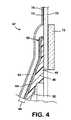
- FIG. 4is an enlarged section showing a detail of the body fitment from FIG. 3 in isolation;
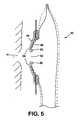
- FIG. 5is a schematic section showing how the pouch of FIG. 3 is prepared for use
- FIG. 6is a schematic section showing the pouch of FIG. 3 in a fitted condition.
- FIG. 7is a schematic section through the body-fitment region of a second embodiment of the invention.
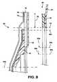
- FIG. 8is an enlarged section showing a detail of FIG. 7 ;
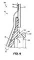
- FIG. 9is a schematic section showing a body-fitment of a third embodiment of the invention.
- FIG. 10is a schematic section showing a body-fitment of a fourth embodiment of the invention.
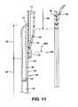
- FIG. 11is a schematic section showing a body-fitment of a fifth embodiment of the invention.
- a first embodiment of the inventionis illustrated in the form of a one-piece pouch 30 .
- This application of a shapeable adhesive with a one-piece pouchis believed to be novel in one non-limiting aspect of the invention.
- the pouch 30comprises front and rear walls, 32 and 34 respectively, welded together around their periphery 36 to define a pouch envelope.
- the walls 32 and 34are of a liquid and gas impermeable material, for example, a laminate of one or more layers of polyvinylethylene (PVE) and a barrier layer of polyvinyledine chloride (PVDC).
- a comfort layer 38 of a soft, cushioning materialmay be provided outside the front and rear walls 32 and 34 , and secured in the weld at the periphery 36 .
- the pouch 30may be provided with a conventional filtered vent for allowing gases to vent through a deodorizing filter.
- the bottom of the pouch 30may be closed, or it may be provided with a closable, drainage chute for allowing the pouch contents to be drained.
- the rear wall 34includes a stomal aperture 40 for receiving body waste from a wearer's stoma 41 (FIGS. 5 and 6 ).
- An adhesive body fitment 42is secured to the rear wall 34 around the stomal aperture 40 for adhesively fastening the pouch 30 to a peristomal region of the body.
- the fitment 42comprises a pad 44 of a pliable and/or moldable and/or shapeable body adhesive, mounted around a shape defining member 46 .
- the shape defining member 46is of a resiliently flexible, but relatively stiff, plastics. The shape defining member 46 can therefore be flexed in use during fitting and wearing of the pouch 30 , but returns towards its natural shape to support the adhesive pad 44 , and to apply pressure to the skin. In this embodiment, the shape defining member 46 is shaped to define a bulge towards the stoma, for applying pressure to the skin around the stoma, to encourage protrusion of the stoma.
- the body defining membergenerally includes a base 48 from which extends a convex-shaped wall 50 . In a region adjacent to the base 48 , the plastics may have a greater thickness, providing increased stiffness in this region.
- the adhesive pad 44 and the shape defining member 46are both of a generally closed loop shape, in this embodiment circular or annular.
- the diameter of the central aperture 52 in the adhesive pad 44 (pad aperture)is smaller than the diameter of the central aperture 54 in the shape defining member 46 (member aperture), such that a region 56 of the adhesive 44 extends generally unsupported in the open center of the shape defining member 46 .
- the pad aperture 52may generally be between about 5 mm and 60 mm in diameter, or preferably between about 10 mm and 55 mm, more preferably between about 12 mm and 50 mm. In one form, the pad aperture is generally about 12-14 mm in diameter.
- the diameter of the pad aperture 52may be less than about two thirds of the diameter of the member aperture 54 , more preferably less than about half, more preferably less than about one third.
- the width of the adhesive from an edge of the member aperture 46 to a closest edge of the pad aperture 52may be at least 3 mm, more preferably at least 5 mm, more preferably at least 7 mm.
- the combination of the shapeable adhesive 44 and the shape defining member 46therefore defines a first zone 60 and a second zone 58 .
- the adhesive 44has a well defined shape (defined by the underlying shape defining member 46 ).
- the adhesive 44can be pliably shaped by the ostomate to create a central aperture 52 of any desired size and shape, and to create a customized shape or profile in the adhesive to fit snugly around his or her stoma.
- the adhesive pad 44has a substantially uniform thickness from one edge to an opposite edge, through both the first and second zones 60 and 58 .
- this designremoves the need for the adhesive thickness in the second zone 58 to be reduced in order to provide a different material characteristic from the first zone 60 .
- This difference in characteristicis provided instead by the underlying shape defining member 46 in the second zone 58 .
- the adhesive pad 44has a substantially uniform consistency, being the same in both the first and second zones 58 and 60 .
- this designremoves the need to use different adhesive consistencies for the first and second zones 58 and 60 to provide different material characteristics.
- This difference in characteristicis provided instead by the underlying shape defining member 46 in the second zone 58 .
- the adhesive pad 44comprises a laminate of a first adhesive layer 62 and a second adhesive layer 64 sandwiching a layer 66 of a flexible plastics, for example, polyethylene.
- the pad 44is shapeable, in that the pliable nature of the adhesive layers 62 and 64 and of the plastics 66 permits the pad to be substantially folded or rolled from an edge.
- the first adhesive layer 62provides a first adhesive surface for contacting the wearer's skin (see FIG. 6 ), and the second adhesive layer 64 provides a second adhesive surface opposite the first adhesive surface.
- the shape defining member 46contacts and substantially covers the second adhesive surface, so that the second adhesive surface is substantially non-exposed.
- the second adhesive surfacemay also be contacted and substantially covered by a flexible microporous adhesive patch 70 .
- the second adhesive surfacei.e. facing away from the body and towards the interior of the pouch
- This exposed adhesive surfacepermits the pad aperture 52 to be re-shaped or enlarged by rolling and/or folding back a rim portion 80 of the pad around the pad aperture 52 , into adhesive contact with a portion of the second adhesive surface of the pad 44 facing away from the body.
- the adhesive contactmay at least partly secure the re-shaped rim 80 in its new shape, or at least partly balance internal forces in the adhesive pad 44 , so that the rim 80 can retain its new shape, at least temporarily during the fitting of the body fitment 42 to the peristomal area of the body.
- the layer 66 of flexible plastics in the laminate of the adhesive pad 46may be embossed and may serve to provide structural integrity for the pad 44 , and also to maintain the pad in a sheet-based form, even after reshaping of the rim 80 .
- the layer 66may also be at least partly resilient, and may tend to cause the adhesive pad 44 to tighten slightly around a stoma after re-shaping, in order to ensure a snug fit around the stoma.
- the adhesivemay be generally not transferable from one zone 58 , 60 to another.
- the adhesive in each layeris generally not transferable from the second zone 58 to the first zone 60 .
- the first adhesive layer 62that provides the skin-contacting adhesive surface, extends across both the first and second zones 60 and 58 .
- first and second adhesive layers 62 and 64may be used for the first and second adhesive layers 62 and 64 .
- a hypoallergenic hydrocolloid based adhesiveis preferred, such as that produced by ConvaTec under the name Durahesive.
- Such an adhesiveis generally tacky, putty-like, and substantially non-elastic, with low memory.
- the first adhesive layer 62may be thicker than the second adhesive layer 64 .
- the first adhesive layer 62may have a thickness of between about 1 mm and 1.5 mm, typically about 1.27 mm.
- the second adhesive layermay have a thickness of between about 0.2 mm and 1 mm, typically about 0.5 mm.
- the microporous adhesive fabric patch 70extends radially outside the body adhesive 44 .
- the body fitment 42also includes a conventional belt attachment ring 72 having horizontally disposed belt attachment lugs (not visible in the drawings) for allowing additional support for the pouch from a belt (not shown).
- the belt attachment ring 72is formed separately from the shape defining member 46 , and the two are secured as part of a unitary assembly using, for example, plastics welding.
- the belt attachment ring 72 and the shape defining member 46may instead be integrally molded.
- the body-facing surface (first adhesive surface) of the adhesive pad 44 and of the fabric patch 70are initially covered with suitable cover sheets 74 and 76 , which may be of, or coated with, a suitable material (e.g. silicon) to aid release from the adhesive surfaces.
- the cover sheet for the adhesive pad 44is preferably contoured to match the shape of the adhesive 44 and may, advantageously, include a central depression for locating in the central aperture 52 of the adhesive 44 .
- the second adhesive surface of the adhesive pad 44may, in the first zone 60 , also be protected by a removable release sheet intended to be removed to expose the second adhesive surface when in use.
- the userfirst removes the protective cover sheet ( 74 not shown in FIG. 5 ) from the adhesive pad 44 . Using, for example, a finger, the user then shapes the region 56 of the adhesive in the central aperture of the shape defining member 46 , to match his or her shape and size of stoma 41 . Typically, the central aperture 52 will need to be enlarged. Since the user only accesses the adhesive from one side (i.e. from the left in FIGS. 3 and 5 ), the user will typically enlarge the aperture 52 by rolling or folding back the rim 80 of the aperture inwardly, into adhesive contact with the exposed second adhesive surface of the pad 44 . This may form a rolled or folded lip.
- the body fitment 42is then pressed against the peristomal area of the body.
- the shape defining member 46applies pressure to the skin to tend to protrude a recessed stoma 41 , so that the exudate can be directed into the pouch.
- the custom shaped portion (rim 80 ) of the adhesive 44forms a custom fit around the stoma 41 , shaped by the user according to the user's experience and preferences.
- Portions of the cover layer( 76 not shown in FIG. 6 ) can then be peeled from the fabric patch 70 , and the patch 70 can be smoothly adhered to the skin around the body adhesive 44 .
- FIGS. 7 and 8a second embodiment of the invention is shown in the form of a two-piece ostomy appliance. This shares similar features with the first embodiment, and equivalent features are, where appropriate, denoted by the same reference numeral.
- the body fitment 80is not permanently secured to the pouch 30 , but is a separate unit removably attachable to the pouch 30 .
- the body fitment 80consists of the body adhesive pad 44 , the shape defining member 46 and the fabric patch 70 previously described. Additionally, the body fitment includes a coupling portion ( 82 ) for coupling to the pouch 30 .
- the coupling portionis in the form of a flange 82 to which the pouch 30 is adhesively attachable.
- the flange 82may be of a material which may be generally flexible, and may be at least partly resilient to deformation out of its normal plane. The flange may be generally non-stretchable in the plane, or it may be resiliently stretchable.
- a suitable material for the flangeis, for example, polyethylene.
- first layer 62 of adhesive providing the skin contacting adhesive surfaceextends generally in both the first and second zones 60 and 58 .
- the pouch 30comprises a complementary coupling portion 90 in the form of a bag-side, adhesive-bearing flange 92 .
- the adhesivemay be a so-called peelable resealable adhesive known in the art for allowing the adhesive to be removed and re-attached at least a plurality of times while still providing a reliable adhesive attachment.
- the flange 92may be flexible, and may be at least partially resilient to deformation out of its normal flat plane. The flange 92 may be resistant to stretching within the plane, or it may be resiliently stretchable.
- the flange 92is secured to the rear wall 34 of the pouch 30 around the stomal aperture 40 , such that at least a peripheral portion of the flange 92 is unattached, and provides a degree of free movement relative to the pouch wall 34 (in a similar manner to the flange 82 described above).
- a suitable material for the adhesive-bearing flangeis a closed cell polyethylene foam, and the adhesive may be a hypoallergenic pressure-sensitive acrylate adhesive.
- Such an arrangement including flexible flanges 82 and 92may provide a desirable amount of flexibility in the coupling between the pouch and the body fitment, even though the body-fitment includes a relatively rigid shape defining member, or pressure applying member, 46 .
- the inner diameter of the aperture in the bag-side flange 92may be larger than the inner diameter of the shape defining member 46 (delimited by lines 96 a ).
- the inner diameter of the aperture in the bag-side flange 92may also be larger than the outer diameter of the shape-defining member 46 (delimited by lines 96 b ).
- the inner periphery of the bag-side flange 92lies radially or transversely outside the outer periphery of the shape defining member 46 .
- the bag-side flange 92surrounds the shape defining member 46 , but does not directly overlap, or directly overlie, any portion of the shape defining member 46 .
- Thismay be advantageous in preventing compression forces from being applied directly to the shape defining member 46 (which applies pressure to the skin) when the flanges 92 and 82 are pressed together to attach the pouch to the body fitment 80 .
- the flexibility of the flanges 82 and 92permits the flanges to be pressed against each other without undue pressure on the shape defining member 46 .
- the above geometry of the bag-side flange 92 relative to the shape defining member 46can de-couple direct axial forces between the shape-defining member 46 (which applies pressure to the skin), and the pouch 30 . Instead, such forces are applied through the flexible flanges, which provides a degree of shock absorption. Also, during removal of the pouch, the separation forces applied to the flanges 82 and 92 are somewhat decoupled from the shape defining member 46 .
- the inner diameter of the aperture in the bag-side flange 92may lie between the inner and outer diameters of the shape defining member 46 (delimited by lines 96 a and 96 b ).
- the bag-side flange 92may be dimensioned such that, when the bag-side flange 92 is pressed against the flange 82 , the inner periphery of the bag-side flange 92 may at least partly overlap or partly overlie the shape defining member 46 .
- the bag-side flangebut does not substantially overlap or overlie at least a majority of the area of the convex-shaped wall 50 .
- the aperture in the bag-side flangemay be dimensioned as indicated at 94 a or 94 b .
- such a geometryin combination with the flexible flanges 82 and 92 , may substantially decouple the shape defining member 46 , and in particular the convex portion 50 , from direct exposure to external forces during attachment, use and disconnecting of the pouch relative to the body fitment.
- the difference between the inner diameter of the bag-side flange 92 and at least one of the inner and outer diameters of the shape defining member 46may be less than about 20 mm, more preferably less than about 10 mm, and more preferably less than about 5 mm.
- the portion of the flange 82 to which the bag-side flange 92 attachesis an attachment zone or “landing zone” 98 , lying radially or transversely outwardly of at least one of the inner and outer peripheries of the shape defining member 46 .
- a landing zonemay be defined explicitly.
- the position of the landing zone 98may depend on the size of the aperture in the bag-side flange 92 (delimited by lines 94 ).
- the landing zonemay extend to a position 98 a or 98 b , to match a particular diameter of the aperture in the bag-side flange 92 (delimited by lines 94 a and 94 b ).
- the flange 82may be substantially plain, but larger than the bag-side flange 92 to enable the user to center the bag-side flange 92 on the flange 82 by feeling the relative alignment of the flanges.
- a lip(not shown) may also be provided upstanding from the inner or outer periphery one flange, to align the flanges 82 and 92 .
- the second embodimentuses the same shapeable adhesive pad 44 as that described for the first embodiment, it will be appreciated that the same geometric relationship between the flanges 82 and 92 , and the relatively stiff pressure ring 46 , may be used in other embodiments with a conventional, non-shapeable adhesive. The geometric relationship can reduce the exposure of the pressure ring to external forces, either when fitting the pouch, or when the pouch is worn.
- FIG. 9shows an alternative third embodiment in the form of a two-piece ostomy appliance. This embodiment is similar to the second embodiment, and the same reference numerals are used where appropriate.
- the principal difference in the third embodimentis that a mechanical fastening arrangement is used for releasably coupling the pouch to the body fitment 100 , instead of an adhesive fastening arrangement as in the second embodiment.
- the body fitment 100includes the adhesive pad 44 , the shape defining member 46 and the patch 70 described previously.
- a molded plastics coupling ring 102is secured to the base 48 of the shape defining member 46 , for coupling to a bag-side coupling ring (not shown) in a similar manner to that depicted in FIG. 1 .
- Many different mechanical couplingsare known in the art for forming such a releasable connection between a body fitment and a pouch.
- the coupling ring 102comprises an upstanding rib 104 having an outwardly facing locking projection 106 for mechanical engagement with a complementary formation on the bag side coupling ring (not shown).
- the rib 104also carries a deflectable seal fin 108 for sealing against the bag-side coupling ring.
- the shape defining member 46 and the coupling ring 102be molded separately, and then secured together directly or indirectly. This simplifies molding of the desired shapes, which might otherwise be difficult to mold in a single mold. However, in other embodiments, it may be preferred to integrally mold the shape defining member 46 and the coupling ring 102 as a one-piece item.
- FIG. 10shows an alternative fourth embodiment based on the principles of the second embodiment. Equivalent reference numerals are used where appropriate.
- the principal difference in the fourth embodimentis that the convex shape defining member ( 46 ) is replaced by a generally planar shape defining member 46 ′ in the form of a generally flat ring or washer.
- the shape defining member 46 ′ and the adhesive pad 44combine to define the first zone 60 in which the adhesive pad 44 is generally unsupported and is shapeable to fit an individual's stoma, and the second zone 58 ′ in which the adhesive has a well-defined shape, in this case a generally planar shape.
- the geometry between the inner periphery of the landing zone 98 and the outer periphery of the shape-defining member 46 ′is maintained as in the second embodiment, to at least partly decouple the shape-defining member 46 ′ from external forces through the flange 82 .
- the inner periphery of the bag-side flange 92(delimited by lines 94 ) may be dimensioned to lie radially outwardly of the inner periphery of the shape defining member.
- the inner periphery of the bag-side flange 92may also be dimensioned to lie radially outwardly of the outer periphery of the shape defining member (delimited by lines 96 b ).
- the inner periphery of the bag-side flange 92may lie generally between the inner and outer peripheries of the shape defining member 46 ′, for example, as indicated at 94 a.
- the exposed second surface of the adhesive pad 44(facing away from the body side surface of the adhesive pad) is present in the first zone 60 , as in the previous embodiments, to facilitate pliable reshaping of the pad aperture 52 .
- FIG. 11shows a fifth embodiment which is similar to the fourth embodiment, except that the shape defining member 46 ′ of the fourth embodiment is absent. Instead, a backing film 110 of a flexible plastics covers a portion of the second adhesive surface 64 ′ of the adhesive pad 44 .
- the backing film 110 and the adhesive pad 44together define a first zone 60 ′ in which the second adhesive surface 64 ′ is exposed, and a second zone 58 ′ in which the second adhesive surface is non-exposed.
- the exposed second adhesive surface 64 ′facilitates pliable reshaping of the pad aperture 52 (as in the previous embodiments).
- the backing film 110permits the adhesive pad 44 to flex, but the backing film 110 causes the shape of the adhesive pad 44 to be more constrained in the second zone 58 ′ than in the first zone 60 ′.
- the backing film 110also prevents the adhesive being substantially reshaped, and prevents the second adhesive surface 64 ′ being adhered to itself in the second zone 60 ′.
- the adhesive pad 44may comprise the same first and second adhesive layers 62 and 64 , and the flexible sheet 66 , as described in the previous embodiments.
- the flange 82is secured to the backing film 110 at a position 112 near an inner periphery of the backing film 110 , for example by adhesive or by plastics welding.
- the landing zone 98 on the flange 82is radially outside the position 112 of the join between the backing film 110 and the flange 98 .
- the landing zonemay overlap the position 112 of the joint (as indicated in phantom at 98 ′).
- the patch 70may be replaced by a mass of adhesive.
- one or more layers 62 , 64 and 66 , of the adhesive pad 44may be extended radially outwardly to provide a larger adhesive surface facing towards the ostomate's body.
- a distinct layer of a skin adhesivemay be used to back the adhesive pad 44 , and to extend the adhesive surface radially outwardly of the pad.
- the skin adhesivemay, for example, be the same as that used for the adhesive pad 44 .
- One aspect of the inventionenables an integral pad to be used to provide both a first zone in which the pad may be pliably reshaped, and a second zone having a more constrained shape.
- a surface of the adhesive pad facing away from the bodyincludes an exposed region in the first zone, and a substantially non-exposed region in the second zone.
- the exposed surface in the first zonepermits an aperture in the first zone to be reshaped or enlarged by rolling or folding back a rim of the adhesive surrounding the aperture into adhesive contact with a portion of the exposed adhesive surface.
- Another aspect of the inventionprovides an adhesive pad at least a portion of which is pliably reshapeable in a region surrounding a stomal aperture, to permit the aperture to be enlarge or reshaped.
- the reshapeable regioncomprises a laminate of a first adhesive layer, a second adhesive layer and a flexible sheet between the adhesive layers.
- Another aspect of the inventionenables a pliable adhesive pad to be used to provide both a fixed shape zone having a well defined shape, and a reshapeable zone in which a portion of the adhesive pad can be manually reshaped to fit an individual's stoma.
- the adhesive padcan be of uniform thickness and consistency in both zones, avoiding the need to provide different adhesive masses, consistencies or thicknesses to define two different zone characteristics. Also, this aspect allows a pressure applying member to be used with a shapeable adhesive.
- Another aspect of the inventionenables a one-piece pouch to be provided using a shapeable adhesive providing a user-shapeable stomal aperture which can be manually reshaped from the body-facing side.
- Another aspect of the inventionprovides an advantageous geometry for utilizing one or more flexible flanges with a shape defining member or with a pressure applying member for applying pressure to the skin to protrude a recessed stoma.
- the geometrycan reduce the exposure of the member to external forces.
Landscapes
- Health & Medical Sciences (AREA)
- General Health & Medical Sciences (AREA)
- Veterinary Medicine (AREA)
- Engineering & Computer Science (AREA)
- Animal Behavior & Ethology (AREA)
- Biomedical Technology (AREA)
- Heart & Thoracic Surgery (AREA)
- Public Health (AREA)
- Life Sciences & Earth Sciences (AREA)
- Nursing (AREA)
- Epidemiology (AREA)
- Orthopedic Medicine & Surgery (AREA)
- Vascular Medicine (AREA)
- Pulmonology (AREA)
- Chemical & Material Sciences (AREA)
- Dispersion Chemistry (AREA)
- Emergency Medicine (AREA)
- Hematology (AREA)
- Anesthesiology (AREA)
- Orthopedics, Nursing, And Contraception (AREA)
- Materials For Medical Uses (AREA)
Abstract
Description
- a first zone in which the second adhesive surface is substantially exposed at least in use, and
- a second zone in which the second adhesive surface is contacted by the backing to substantially cover the second adhesive surface.
- a first fixed-shape zone in which the adhesive is supported by, and has a shape defined by, the shape defining member; and
- a second shapeable zone in the which the adhesive pad is unsupported by the shape defining member, and is shapeable to enable the pad and an aperture therein to be custom shaped to fit an individual's stoma.
Claims (22)
Priority Applications (19)
| Application Number | Priority Date | Filing Date | Title |
|---|---|---|---|
| US10/188,535US6840924B2 (en) | 2002-07-03 | 2002-07-03 | Ostomy appliance |
| NZ526382ANZ526382A (en) | 2002-07-03 | 2003-06-10 | Ostomy appliance having a pliable zone to allow manual enlargement of the aperture for stoma |
| ZA2003/04558AZA200304558B (en) | 2002-07-03 | 2003-06-11 | Ostomy appliance |
| DE60305798TDE60305798T2 (en) | 2002-07-03 | 2003-06-16 | ostomy appliance |
| ES03013344TES2266686T5 (en) | 2002-07-03 | 2003-06-16 | Ostomy device |
| DK03013344.1TDK1378219T4 (en) | 2002-07-03 | 2003-06-16 | An ostomy appliance |
| EP06004694AEP1666008B1 (en) | 2002-07-03 | 2003-06-16 | Ostomy appliance |
| AT03013344TATE328556T1 (en) | 2002-07-03 | 2003-06-16 | STOMARY APPARATUS |
| CA2432465ACA2432465C (en) | 2002-07-03 | 2003-06-16 | Ostomy appliance |
| DK06004694.3TDK1666008T3 (en) | 2002-07-03 | 2003-06-16 | An ostomy appliance |
| EP03013344AEP1378219B2 (en) | 2002-07-03 | 2003-06-16 | Ostomy appliance |
| ES06004694TES2393735T3 (en) | 2002-07-03 | 2003-06-16 | Ostomy device |
| MXPA03005983AMXPA03005983A (en) | 2002-07-03 | 2003-07-01 | DEVICE FOR OSTOMY. |
| AU2003207085AAU2003207085B2 (en) | 2002-07-03 | 2003-07-02 | Ostomy Appliance |
| JP2003191284AJP4503944B2 (en) | 2002-07-03 | 2003-07-03 | Ostomy appliance |
| US10/971,416US20050054997A1 (en) | 2002-07-03 | 2004-10-22 | Ostomy appliance |
| AU2008203184AAU2008203184B2 (en) | 2002-07-03 | 2008-07-17 | Ostomy appliance |
| JP2009241541AJP5139398B2 (en) | 2002-07-03 | 2009-10-20 | Ostomy appliance |
| JP2012197676AJP2013006067A (en) | 2002-07-03 | 2012-09-07 | Ostomy appliance |
Applications Claiming Priority (1)
| Application Number | Priority Date | Filing Date | Title |
|---|---|---|---|
| US10/188,535US6840924B2 (en) | 2002-07-03 | 2002-07-03 | Ostomy appliance |
Related Child Applications (1)
| Application Number | Title | Priority Date | Filing Date |
|---|---|---|---|
| US10/971,416DivisionUS20050054997A1 (en) | 2002-07-03 | 2004-10-22 | Ostomy appliance |
Publications (2)
| Publication Number | Publication Date |
|---|---|
| US20040006320A1 US20040006320A1 (en) | 2004-01-08 |
| US6840924B2true US6840924B2 (en) | 2005-01-11 |
Family
ID=29720423
Family Applications (2)
| Application Number | Title | Priority Date | Filing Date |
|---|---|---|---|
| US10/188,535Expired - LifetimeUS6840924B2 (en) | 2002-07-03 | 2002-07-03 | Ostomy appliance |
| US10/971,416AbandonedUS20050054997A1 (en) | 2002-07-03 | 2004-10-22 | Ostomy appliance |
Family Applications After (1)
| Application Number | Title | Priority Date | Filing Date |
|---|---|---|---|
| US10/971,416AbandonedUS20050054997A1 (en) | 2002-07-03 | 2004-10-22 | Ostomy appliance |
Country Status (12)
| Country | Link |
|---|---|
| US (2) | US6840924B2 (en) |
| EP (2) | EP1378219B2 (en) |
| JP (3) | JP4503944B2 (en) |
| AT (1) | ATE328556T1 (en) |
| AU (2) | AU2003207085B2 (en) |
| CA (1) | CA2432465C (en) |
| DE (1) | DE60305798T2 (en) |
| DK (2) | DK1666008T3 (en) |
| ES (2) | ES2393735T3 (en) |
| MX (1) | MXPA03005983A (en) |
| NZ (1) | NZ526382A (en) |
| ZA (1) | ZA200304558B (en) |
Cited By (25)
| Publication number | Priority date | Publication date | Assignee | Title |
|---|---|---|---|---|
| US20030204175A1 (en)* | 2002-04-30 | 2003-10-30 | Mahoney James L. | Support device for ostomy appliance |
| US20040193123A1 (en)* | 2003-03-31 | 2004-09-30 | Fenton Gary H. | Ostomy pouch with stretch-to-fit stoma opening |
| US20050096611A1 (en)* | 2003-10-30 | 2005-05-05 | Stoyer Brian C. | Multi-adhesive medical appliance |
| US20050106225A1 (en)* | 2003-09-16 | 2005-05-19 | Roger Massengale | Fluid medication delivery device |
| US20070185464A1 (en)* | 2006-02-03 | 2007-08-09 | Bristol-Myers Squibb Company | Ostomy appliance with recovery resistant moldable adhesive |
| US20080071237A1 (en)* | 2006-09-20 | 2008-03-20 | Tisteron, Ltd. | Disposable waste containment article and a combination of two articles worn simultaneously |
| US7421743B1 (en)* | 2007-08-29 | 2008-09-09 | Wixom David V | Ostomy garment apparatus |
| US20090076472A1 (en)* | 2007-09-17 | 2009-03-19 | Tisteron, Ltd. | Absorbent layer, structure and article along with a method of forming the same |
| US20100114045A1 (en)* | 2007-04-09 | 2010-05-06 | Bristol-Myers Squibb Company | Ostomy pouch appliane |
| US20100114044A1 (en)* | 2007-04-09 | 2010-05-06 | Cramer Kathryn E | Adhesive body fitment for ostomy appliane |
| US20100324511A1 (en)* | 2009-06-17 | 2010-12-23 | Hollister Incorporated | Ostomy faceplate having moldable adhesive wafer with diminishing surface undulations |
| US20110118684A1 (en)* | 2008-07-16 | 2011-05-19 | Convatec Technologies Inc. | Adhesive ostomy coupling |
| US20110213322A1 (en)* | 2008-11-19 | 2011-09-01 | Convatec Technologies Inc. | Ostomy appliance with moldable adhesive |
| US20120123363A1 (en)* | 2009-05-01 | 2012-05-17 | Hollister Incorporated | Ostomy appliance coupling system and an ostomy appliance |
| US20120283677A1 (en)* | 2009-11-27 | 2012-11-08 | Coloplast A/S | body waste collecting device |
| USD676550S1 (en)* | 2012-03-22 | 2013-02-19 | Hollister Incorporated | Expandable ostomy appliance |
| US20140350498A1 (en)* | 2010-04-16 | 2014-11-27 | Kci Licensing, Inc. | Evaporative body-fluid containers and methods |
| US20140378919A1 (en)* | 2013-06-22 | 2014-12-25 | Jezekiel Ben-Arie | Easily Washable and Drainable Pouch |
| US9078759B2 (en)* | 2010-11-25 | 2015-07-14 | Erland As | Stoma-leakage collecting device, attachment plate and assembly thereof |
| JP2016525412A (en)* | 2013-07-23 | 2016-08-25 | コンバテック・テクノロジーズ・インコーポレイテッドConvatec Technologies Inc | Molded adhesive wafer |
| US9498372B2 (en) | 2008-11-19 | 2016-11-22 | Convatec Technologies Inc. | Ostomy pouch appliance |
| EP3639796A1 (en) | 2018-10-19 | 2020-04-22 | Advanced Medical Solutions Limited | Ostomy device |
| US20200253777A1 (en)* | 2019-02-07 | 2020-08-13 | Convatec Technologies Inc. | Adjustable convex ostomy device |
| US11071640B2 (en)* | 2012-11-20 | 2021-07-27 | Convatec Technologies Inc. | One piece ostomy pouch enhancements |
| US11918508B1 (en)* | 2022-09-01 | 2024-03-05 | Hollister Incorporated | Ostomy appliance for providing customized and localized convex support |
Families Citing this family (78)
| Publication number | Priority date | Publication date | Assignee | Title |
|---|---|---|---|---|
| GB2418860B (en)* | 2004-09-24 | 2009-11-11 | Welland Medical Ltd | Reinforced pads for ostomy bags |
| GB2428381A (en)* | 2005-06-14 | 2007-01-31 | Welland Medical Ltd | Improved adhesive pads for ostomy bags |
| JP4743501B2 (en)* | 2005-09-09 | 2011-08-10 | 独立行政法人国立循環器病研究センター | Stoma |
| AU2014202247B2 (en)* | 2007-04-09 | 2016-01-14 | Convatec Technologies Inc. | Ostomy pouch appliance |
| EP2108345A1 (en)* | 2008-04-11 | 2009-10-14 | Eurotec Beheer B.V. | A 1-piece stoma system with a soft, extensible stoma opening |
| US20120078208A1 (en)* | 2010-09-25 | 2012-03-29 | Laudick David A | Contained ostomy appliance |
| US8460259B2 (en) | 2010-11-02 | 2013-06-11 | Convatec Technologies, Inc. | Controlled discharge ostomy appliance and moldable adhesive wafer |
| BR112013013519B1 (en)* | 2010-12-17 | 2020-10-20 | Coloplast A/S | ostomy wafer |
| EP3175830B1 (en)* | 2010-12-17 | 2020-06-24 | Coloplast A/S | A convex supporting device for an ostomy appliance |
| GB2498974B (en)* | 2012-02-01 | 2017-09-27 | Pelican Healthcare Ltd | A mounting for an ostomy pouch |
| ES2636623T3 (en)* | 2012-12-06 | 2017-10-06 | Coloplast A/S | An adaptable ostomy motherboard |
| GB2509752B (en)* | 2013-01-14 | 2019-06-26 | Pelican Healthcare Ltd | An ostomy pouch assembly |
| EP3082665B1 (en)* | 2013-12-18 | 2018-03-07 | Coloplast A/S | An adaptable ostomy base plate |
| US10531977B2 (en) | 2014-04-17 | 2020-01-14 | Coloplast A/S | Thermoresponsive skin barrier appliances |
| EP2957268A1 (en)* | 2014-06-17 | 2015-12-23 | University of Limerick | An ostomy pouching system |
| USD758572S1 (en)* | 2014-06-20 | 2016-06-07 | Integrated Healing Technologies, Llc. | Wound drain dome |
| CN107206118A (en)* | 2015-01-28 | 2017-09-26 | 霍利斯特股份有限公司 | For the stoma edge device for moistening the adhesive of tissue and being made using the adhesive |
| WO2016146135A1 (en)* | 2015-03-16 | 2016-09-22 | Coloplast A/S | Ostomy device |
| PL3346961T3 (en)* | 2015-09-11 | 2020-11-16 | Coloplast A/S | Ostomy device |
| RU2721076C2 (en) | 2015-10-20 | 2020-05-15 | Колопласт А/С | Stoma apparatus |
| RU2740679C2 (en) | 2016-05-04 | 2021-01-19 | Колопласт А/С | Adhesive plate with matrix with neutraliser |
| RU2740844C2 (en)* | 2016-09-21 | 2021-01-21 | Колопласт А/С | Stoma apparatus |
| SG11202003202RA (en)* | 2017-10-09 | 2020-05-28 | The Insides Company Ltd | Nutrient recycling device |
| RU2020117765A (en) | 2017-11-08 | 2021-12-08 | Колопласт А/С | ADHESIVE PLATE WITH MATRIX WITH CONVERTER |
| EP3706673B1 (en) | 2017-11-08 | 2024-04-03 | Coloplast A/S | An adhesive wafer with a neutralizer matrix |
| EP4245273A3 (en) | 2017-12-22 | 2023-11-08 | Coloplast A/S | Base plate and sensor assembly of an ostomy system having a leakage sensor |
| AU2018391313B2 (en) | 2017-12-22 | 2024-05-02 | Coloplast A/S | Accessory devices of an ostomy system, and related methods for communicating operating state |
| US11707377B2 (en) | 2017-12-22 | 2023-07-25 | Coloplast A/S | Coupling part with a hinge for a medical base plate and sensor assembly part |
| US11559426B2 (en)* | 2017-12-22 | 2023-01-24 | Coloplast A/S | System including a skin-engageable element of a medical appliance |
| US11654043B2 (en) | 2017-12-22 | 2023-05-23 | Coloplast A/S | Sensor assembly part and a base plate for a medical appliance and a method for manufacturing a base plate or a sensor assembly part |
| EP3727219B1 (en) | 2017-12-22 | 2023-08-09 | Coloplast A/S | Moisture detecting base plate for an ostomy appliance and a system for determining moisture propagation in a base plate and/or a sensor assembly part |
| US10799385B2 (en) | 2017-12-22 | 2020-10-13 | Coloplast A/S | Ostomy appliance with layered base plate |
| US10849781B2 (en) | 2017-12-22 | 2020-12-01 | Coloplast A/S | Base plate for an ostomy appliance |
| US11627891B2 (en) | 2017-12-22 | 2023-04-18 | Coloplast A/S | Calibration methods for medical appliance tools |
| JP7462558B2 (en) | 2017-12-22 | 2024-04-05 | コロプラスト アクティーゼルスカブ | Ostomy system and monitor device with angular leak detection - Patents.com |
| WO2019120438A1 (en) | 2017-12-22 | 2019-06-27 | Coloplast A/S | Tools and methods for placing an ostomy appliance on a user |
| WO2019120442A1 (en) | 2017-12-22 | 2019-06-27 | Coloplast A/S | Sensor assembly part and a base plate for an ostomy appliance and a device for connecting to a base plate or a sensor assembly part |
| EP3727222B1 (en) | 2017-12-22 | 2024-05-08 | Coloplast A/S | Sensor assembly part for an ostomy appliance and a method for manufacturing a sensor assembly part |
| US11607334B2 (en) | 2017-12-22 | 2023-03-21 | Coloplast A/S | Base plate for a medical appliance, a monitor device and a system for a medical appliance |
| WO2019120441A1 (en) | 2017-12-22 | 2019-06-27 | Coloplast A/S | Sensor assembly part and a base plate for an ostomy appliance and a method for manufacturing a sensor assembly part and a base plate |
| LT3727228T (en) | 2017-12-22 | 2022-08-10 | Coloplast A/S | MAIN BOARD AND SENSOR STRUCTURE PART FOR OSTOMY DEVICE AND METHOD OF MANUFACTURING THE MAIN BOARD AND SENSOR STRUCTURE PART |
| US10500084B2 (en) | 2017-12-22 | 2019-12-10 | Coloplast A/S | Accessory devices of an ostomy system, and related methods for communicating leakage state |
| LT4032510T (en) | 2017-12-22 | 2025-08-25 | Coloplast A/S | BASE BOARD WITH SELECTIVE SENSOR POINTS AND METHOD FOR MANUFACTURING THEREOF |
| EP4248920A3 (en) | 2017-12-22 | 2023-12-27 | Coloplast A/S | Ostomy appliance system, monitor device, and method of monitoring an ostomy appliance |
| DK3729456T3 (en) | 2017-12-22 | 2022-03-07 | Coloplast As | MONITORING DEVICE FOR AN OSTOMY SYSTEM AND ASSOCIATED METHOD FOR OPERATING A MONITORING DEVICE |
| EP4042987B1 (en) | 2017-12-22 | 2025-02-12 | Coloplast A/S | Monitor device of an ostomy system having a connector for coupling to both a base plate and an accessory device |
| WO2019120431A1 (en) | 2017-12-22 | 2019-06-27 | Coloplast A/S | Tools and methods for cutting holes in an ostomy appliance |
| EP4032511A1 (en) | 2017-12-22 | 2022-07-27 | Coloplast A/S | Ostomy appliance with sensing zones |
| EP3727245B1 (en) | 2017-12-22 | 2025-04-30 | Coloplast A/S | Data transmission schemes for an ostomy system, monitoring device for an ostomy device, and associated methods |
| US11471318B2 (en) | 2017-12-22 | 2022-10-18 | Coloplast A/S | Data collection schemes for a medical appliance and related methods |
| EP3727231B2 (en) | 2017-12-22 | 2025-03-12 | Coloplast A/S | Processing schemes for an ostomy system, monitor device for an ostomy appliance and related methods |
| JP2021508269A (en) | 2017-12-22 | 2021-03-04 | コロプラスト アクティーゼルスカブ | A method for manufacturing a base plate for an ostomy orthosis and a sensor assembly part for the base plate, and a base plate and a sensor assembly part. |
| US12208029B2 (en) | 2018-02-20 | 2025-01-28 | Coloplast A/S | Base plate having a mechanical and electrical connector |
| EP4631480A2 (en) | 2018-02-20 | 2025-10-15 | Coloplast A/S | Accessory devices of an ostomy system, and related methods for changing an ostomy appliance based on future operating state |
| WO2019161861A1 (en) | 2018-02-20 | 2019-08-29 | Coloplast A/S | Sensor assembly part and a base plate for an ostomy appliance and a device for connecting to a base plate and/or a sensor assembly part |
| US11998474B2 (en) | 2018-03-15 | 2024-06-04 | Coloplast A/S | Apparatus and methods for navigating ostomy appliance user to changing room |
| US11903728B2 (en) | 2018-03-15 | 2024-02-20 | Coloplast A/S | Methods of configuring medical notifications and related accessory devices |
| CN108852604A (en)* | 2018-08-07 | 2018-11-23 | 桐乡市宝禾医疗器械有限公司 | A kind of ostomy bag convex surface chassis |
| EP3837520B1 (en) | 2018-08-15 | 2025-10-08 | Coloplast A/S | Accessory device of an ostomy system and related methods for issue identification |
| EP3856308B1 (en)* | 2018-09-27 | 2025-08-13 | Coloplast A/S | Tracheostoma device holder |
| US11523601B2 (en)* | 2018-10-26 | 2022-12-13 | Woodstream Corporation | Insect control device and method for household outdoor garbage receptacles |
| EP3897482B1 (en) | 2018-12-20 | 2025-07-16 | Coloplast A/S | Ostomy condition classification with image data transformation, devices and related methods |
| EP3897481B1 (en) | 2018-12-20 | 2023-08-09 | Coloplast A/S | Ostomy condition classification with masking, devices and related methods |
| WO2020156624A1 (en) | 2019-01-31 | 2020-08-06 | Coloplast A/S | Application of a stomal sensor patch |
| US11612512B2 (en) | 2019-01-31 | 2023-03-28 | Coloplast A/S | Moisture detecting base plate for an ostomy appliance and a system for determining moisture propagation in a base plate and/or a sensor assembly part |
| KR102825171B1 (en) | 2019-01-31 | 2025-06-25 | 컬러플라스트 에이/에스 | Sensor patch for ostomy/urinary device |
| CN113365582B (en) | 2019-01-31 | 2024-12-31 | 科洛普拉斯特公司 | Stoma Sensor Patch |
| US12257172B2 (en) | 2019-02-28 | 2025-03-25 | Coloplast A/S | Sensor patch for attachment to a base plate |
| CN113645928B (en)* | 2019-04-01 | 2024-03-12 | 科洛普拉斯特公司 | Flexible skin barrier ring |
| BR112021021146A2 (en)* | 2019-04-25 | 2021-12-14 | Convatec Technologies Inc | Ostomy baseplates incorporating adhesives, ostomy devices including the same, and methods of applying the ostomy baseplates and ostomy devices |
| BR112021021315A2 (en) | 2019-04-25 | 2022-01-18 | Convatec Technologies Inc | Ostomy plates incorporating adhesives and foam layers, devices including same and application methods |
| BR112021021279A2 (en)* | 2019-04-25 | 2022-01-18 | Convatec Technologies Inc | Perforated chamber ostomy plates, devices including same and application methods |
| CA3154934A1 (en)* | 2019-12-06 | 2021-06-10 | Hollister Incorporated | Soft convex ostomy appliance |
| EP4512377A3 (en) | 2020-04-14 | 2025-04-30 | Coloplast A/S | METHOD FOR A MONITORING DEVICE FOR A PERSONAL CARE SYSTEM |
| CN114246724A (en)* | 2021-12-13 | 2022-03-29 | 四川大学华西医院 | an enterostomy device |
| WO2024206576A1 (en) | 2023-03-30 | 2024-10-03 | Convatec Limited | An ostomy body fitment |
| WO2024206566A1 (en) | 2023-03-30 | 2024-10-03 | Convatec Limited | An ostomy body fitment |
| WO2025027285A1 (en) | 2023-07-28 | 2025-02-06 | Convatec Limited | A release layer/backing laver for an ostomy body fitment |
Citations (10)
| Publication number | Priority date | Publication date | Assignee | Title |
|---|---|---|---|---|
| US3683918A (en) | 1971-02-02 | 1972-08-15 | Raymond R Pizzella | Disposable bag for medical uses |
| EP0276042A2 (en) | 1983-12-19 | 1988-07-27 | E.R. Squibb & Sons, Inc. | Ostomy aplliance |
| US5496296A (en)* | 1994-06-06 | 1996-03-05 | Dansac A/S | Ostomy appliance with extrudable gasket |
| US5501678A (en)* | 1991-08-30 | 1996-03-26 | Coloplast A/S | Adapter for use in connection with ostomy equipment |
| US5609585A (en)* | 1995-08-01 | 1997-03-11 | Hollister Incorporated | Wafer having adhesive skin barrier layer |
| US5618276A (en) | 1996-02-14 | 1997-04-08 | Hollister Incorporated | Ostomy appliance with convex pressure ring |
| GB2322302A (en) | 1997-02-19 | 1998-08-26 | Pelican Healthcare Ltd | Ostomy coupling |
| WO2000053133A1 (en)* | 1999-03-09 | 2000-09-14 | Welland Medical Limited | Adhesive pads for ostomy bags |
| US6332879B1 (en) | 1997-05-26 | 2001-12-25 | Coloplast A/S | Ostomy appliance |
| US6569134B1 (en)* | 2000-06-14 | 2003-05-27 | Hollister Incorporated | Reformable convex adapter for ostomy appliance and method of use |
Family Cites Families (9)
| Publication number | Priority date | Publication date | Assignee | Title |
|---|---|---|---|---|
| BE819488A (en) | 1973-09-04 | 1974-12-31 | SEALING FOR USE WITH AN AUXILIARY OSTOMY DEVICE | |
| US4166051A (en)* | 1977-06-08 | 1979-08-28 | E. R. Squibb & Sons, Inc. | Ostomy composition |
| US4204540A (en)* | 1977-06-08 | 1980-05-27 | E. R. Squibb & Sons, Inc. | Ostomy composition |
| GB8333711D0 (en)* | 1983-12-19 | 1984-01-25 | Craig Med Prod Ltd | Ostomy appliance |
| US4786284A (en)* | 1986-03-03 | 1988-11-22 | Silber Arthur L | Disconnectible section ostomy appliance |
| NZ234877A (en) | 1989-08-28 | 1994-01-26 | Squibb & Sons Inc | Faceplate, for an ostomy device, having a convex upper surface portion |
| US5545154A (en)* | 1994-12-28 | 1996-08-13 | E. R. Squibb & Sons, Inc. | Ostomy device |
| ATE320779T1 (en)* | 1996-10-22 | 2006-04-15 | Coloplast As | OSTOMY DEVICE |
| DK172791B1 (en) | 1997-05-26 | 1999-07-19 | Coloplast As | An ostomy appliance |
- 2002
- 2002-07-03USUS10/188,535patent/US6840924B2/ennot_activeExpired - Lifetime
- 2003
- 2003-06-10NZNZ526382Apatent/NZ526382A/ennot_activeIP Right Cessation
- 2003-06-11ZAZA2003/04558Apatent/ZA200304558B/enunknown
- 2003-06-16ESES06004694Tpatent/ES2393735T3/ennot_activeExpired - Lifetime
- 2003-06-16DEDE60305798Tpatent/DE60305798T2/ennot_activeExpired - Lifetime
- 2003-06-16DKDK06004694.3Tpatent/DK1666008T3/enactive
- 2003-06-16DKDK03013344.1Tpatent/DK1378219T4/enactive
- 2003-06-16EPEP03013344Apatent/EP1378219B2/ennot_activeExpired - Lifetime
- 2003-06-16CACA2432465Apatent/CA2432465C/ennot_activeExpired - Lifetime
- 2003-06-16ESES03013344Tpatent/ES2266686T5/ennot_activeExpired - Lifetime
- 2003-06-16EPEP06004694Apatent/EP1666008B1/ennot_activeExpired - Lifetime
- 2003-06-16ATAT03013344Tpatent/ATE328556T1/ennot_activeIP Right Cessation
- 2003-07-01MXMXPA03005983Apatent/MXPA03005983A/enactiveIP Right Grant
- 2003-07-02AUAU2003207085Apatent/AU2003207085B2/ennot_activeExpired
- 2003-07-03JPJP2003191284Apatent/JP4503944B2/ennot_activeExpired - Lifetime
- 2004
- 2004-10-22USUS10/971,416patent/US20050054997A1/ennot_activeAbandoned
- 2008
- 2008-07-17AUAU2008203184Apatent/AU2008203184B2/ennot_activeExpired
- 2009
- 2009-10-20JPJP2009241541Apatent/JP5139398B2/ennot_activeExpired - Lifetime
- 2012
- 2012-09-07JPJP2012197676Apatent/JP2013006067A/enactivePending
Patent Citations (10)
| Publication number | Priority date | Publication date | Assignee | Title |
|---|---|---|---|---|
| US3683918A (en) | 1971-02-02 | 1972-08-15 | Raymond R Pizzella | Disposable bag for medical uses |
| EP0276042A2 (en) | 1983-12-19 | 1988-07-27 | E.R. Squibb & Sons, Inc. | Ostomy aplliance |
| US5501678A (en)* | 1991-08-30 | 1996-03-26 | Coloplast A/S | Adapter for use in connection with ostomy equipment |
| US5496296A (en)* | 1994-06-06 | 1996-03-05 | Dansac A/S | Ostomy appliance with extrudable gasket |
| US5609585A (en)* | 1995-08-01 | 1997-03-11 | Hollister Incorporated | Wafer having adhesive skin barrier layer |
| US5618276A (en) | 1996-02-14 | 1997-04-08 | Hollister Incorporated | Ostomy appliance with convex pressure ring |
| GB2322302A (en) | 1997-02-19 | 1998-08-26 | Pelican Healthcare Ltd | Ostomy coupling |
| US6332879B1 (en) | 1997-05-26 | 2001-12-25 | Coloplast A/S | Ostomy appliance |
| WO2000053133A1 (en)* | 1999-03-09 | 2000-09-14 | Welland Medical Limited | Adhesive pads for ostomy bags |
| US6569134B1 (en)* | 2000-06-14 | 2003-05-27 | Hollister Incorporated | Reformable convex adapter for ostomy appliance and method of use |
Cited By (53)
| Publication number | Priority date | Publication date | Assignee | Title |
|---|---|---|---|---|
| US6929627B2 (en)* | 2002-04-30 | 2005-08-16 | James L. Mahoney | Support device for ostomy appliance |
| US20030204175A1 (en)* | 2002-04-30 | 2003-10-30 | Mahoney James L. | Support device for ostomy appliance |
| US20040193123A1 (en)* | 2003-03-31 | 2004-09-30 | Fenton Gary H. | Ostomy pouch with stretch-to-fit stoma opening |
| US7029464B2 (en)* | 2003-03-31 | 2006-04-18 | Marlen Manufacturing & Development Co. | Ostomy pouch with stretch-to-fit stoma opening |
| US8241269B2 (en) | 2003-09-16 | 2012-08-14 | Kimberly-Clark Worldwide, Inc. | Fluid medication delivery device |
| US20050106225A1 (en)* | 2003-09-16 | 2005-05-19 | Roger Massengale | Fluid medication delivery device |
| US7771413B2 (en)* | 2003-09-16 | 2010-08-10 | I-Flow Corporation | Fluid medication delivery device |
| US8323266B2 (en) | 2003-09-16 | 2012-12-04 | Kimberly-Clark Worldwide, Inc. | Fluid medication delivery device |
| US20050096611A1 (en)* | 2003-10-30 | 2005-05-05 | Stoyer Brian C. | Multi-adhesive medical appliance |
| US20070185464A1 (en)* | 2006-02-03 | 2007-08-09 | Bristol-Myers Squibb Company | Ostomy appliance with recovery resistant moldable adhesive |
| US8690846B2 (en) | 2006-09-20 | 2014-04-08 | Tisteron, Ltd. | Combination of two disposable waste containment articles worn simultaneously |
| US20110213324A1 (en)* | 2006-09-20 | 2011-09-01 | Tisteron, Ltd. | Combination of two disposable waste containment articles worn simultaneously |
| US20080071237A1 (en)* | 2006-09-20 | 2008-03-20 | Tisteron, Ltd. | Disposable waste containment article and a combination of two articles worn simultaneously |
| US7927320B2 (en) | 2006-09-20 | 2011-04-19 | Tisteron, Ltd. | Disposable waste containment article and a combination of two articles worn simultaneously |
| US20100114045A1 (en)* | 2007-04-09 | 2010-05-06 | Bristol-Myers Squibb Company | Ostomy pouch appliane |
| US20100114044A1 (en)* | 2007-04-09 | 2010-05-06 | Cramer Kathryn E | Adhesive body fitment for ostomy appliane |
| US8343121B2 (en) | 2007-04-09 | 2013-01-01 | Convatec Technologies, Inc. | Ostomy pouch appliance |
| US7421743B1 (en)* | 2007-08-29 | 2008-09-09 | Wixom David V | Ostomy garment apparatus |
| US20090076472A1 (en)* | 2007-09-17 | 2009-03-19 | Tisteron, Ltd. | Absorbent layer, structure and article along with a method of forming the same |
| US20110118684A1 (en)* | 2008-07-16 | 2011-05-19 | Convatec Technologies Inc. | Adhesive ostomy coupling |
| US8708987B2 (en) | 2008-11-19 | 2014-04-29 | Convatec Technologies Inc. | Ostomy appliance with moldable adhesive |
| US20170020713A1 (en)* | 2008-11-19 | 2017-01-26 | Convatec Technologies Inc. | Ostomy pouch appliance |
| US11076979B2 (en)* | 2008-11-19 | 2021-08-03 | Convatec Technologies Inc. | Ostomy pouch appliance |
| US10105255B2 (en)* | 2008-11-19 | 2018-10-23 | Convatec Technologies Inc. | Ostomy pouch appliance |
| US9498372B2 (en) | 2008-11-19 | 2016-11-22 | Convatec Technologies Inc. | Ostomy pouch appliance |
| US20110213322A1 (en)* | 2008-11-19 | 2011-09-01 | Convatec Technologies Inc. | Ostomy appliance with moldable adhesive |
| US9949865B2 (en)* | 2009-05-01 | 2018-04-24 | Hollister Incorporated | Ostomy appliance coupling system and an ostomy appliance |
| US20120123363A1 (en)* | 2009-05-01 | 2012-05-17 | Hollister Incorporated | Ostomy appliance coupling system and an ostomy appliance |
| US8211073B2 (en) | 2009-06-17 | 2012-07-03 | Hollister Incorporated | Ostomy faceplate having moldable adhesive wafer with diminishing surface undulations |
| US20100324511A1 (en)* | 2009-06-17 | 2010-12-23 | Hollister Incorporated | Ostomy faceplate having moldable adhesive wafer with diminishing surface undulations |
| US20120283677A1 (en)* | 2009-11-27 | 2012-11-08 | Coloplast A/S | body waste collecting device |
| US8728047B2 (en)* | 2009-11-27 | 2014-05-20 | Coloplast A/S | Body waste collecting device |
| US12036351B2 (en) | 2010-04-16 | 2024-07-16 | Solventum Intellectual Properties Company | Dressings and methods for treating a tissue site on a patient |
| US11285247B2 (en)* | 2010-04-16 | 2022-03-29 | Kci Licensing, Inc. | Evaporative body-fluid containers and methods |
| US20140350498A1 (en)* | 2010-04-16 | 2014-11-27 | Kci Licensing, Inc. | Evaporative body-fluid containers and methods |
| US10245358B2 (en)* | 2010-04-16 | 2019-04-02 | Kci Licensing, Inc. | Evaporative body-fluid containers and methods |
| US9078759B2 (en)* | 2010-11-25 | 2015-07-14 | Erland As | Stoma-leakage collecting device, attachment plate and assembly thereof |
| USD676550S1 (en)* | 2012-03-22 | 2013-02-19 | Hollister Incorporated | Expandable ostomy appliance |
| US11071640B2 (en)* | 2012-11-20 | 2021-07-27 | Convatec Technologies Inc. | One piece ostomy pouch enhancements |
| US20140378919A1 (en)* | 2013-06-22 | 2014-12-25 | Jezekiel Ben-Arie | Easily Washable and Drainable Pouch |
| EP4119112A1 (en) | 2013-07-23 | 2023-01-18 | ConvaTec Technologies Inc. | Moldable adhesive wafers |
| US10449082B2 (en) | 2013-07-23 | 2019-10-22 | Convatec Technologies Inc. | Moldable adhesive wafers |
| AU2014293635B2 (en)* | 2013-07-23 | 2019-05-23 | Convatec Technologies Inc. | Moldable adhesive wafers |
| EP3024424A4 (en)* | 2013-07-23 | 2017-03-22 | ConvaTec Technologies Inc. | Moldable adhesive wafers |
| EP3024424B1 (en) | 2013-07-23 | 2022-10-19 | ConvaTec Technologies Inc. | Moldable adhesive wafers |
| JP2016525412A (en)* | 2013-07-23 | 2016-08-25 | コンバテック・テクノロジーズ・インコーポレイテッドConvatec Technologies Inc | Molded adhesive wafer |
| EP3639796A1 (en) | 2018-10-19 | 2020-04-22 | Advanced Medical Solutions Limited | Ostomy device |
| US20200253777A1 (en)* | 2019-02-07 | 2020-08-13 | Convatec Technologies Inc. | Adjustable convex ostomy device |
| US11737906B2 (en)* | 2019-02-07 | 2023-08-29 | Convatec Technologies, Inc. | Adjustable convex ostomy device |
| US20240000601A1 (en)* | 2019-02-07 | 2024-01-04 | Convatec Technologies Inc. | Adjustable convex ostomy device |
| US12076265B2 (en)* | 2019-02-07 | 2024-09-03 | Convatec Technologies Inc. | Adjustable convex ostomy device |
| US11918508B1 (en)* | 2022-09-01 | 2024-03-05 | Hollister Incorporated | Ostomy appliance for providing customized and localized convex support |
| US20240074889A1 (en)* | 2022-09-01 | 2024-03-07 | Hollister Incorporated | Ostomy appliance for providing customized and localized convex support |
Also Published As
| Publication number | Publication date |
|---|---|
| ES2393735T3 (en) | 2012-12-27 |
| JP5139398B2 (en) | 2013-02-06 |
| CA2432465A1 (en) | 2004-01-03 |
| ATE328556T1 (en) | 2006-06-15 |
| JP2013006067A (en) | 2013-01-10 |
| US20050054997A1 (en) | 2005-03-10 |
| AU2003207085A1 (en) | 2004-01-22 |
| ES2266686T5 (en) | 2012-11-07 |
| DE60305798T2 (en) | 2007-06-14 |
| ZA200304558B (en) | 2005-02-23 |
| ES2266686T3 (en) | 2007-03-01 |
| EP1378219B1 (en) | 2006-06-07 |
| JP2010012321A (en) | 2010-01-21 |
| EP1378219A2 (en) | 2004-01-07 |
| AU2003207085B2 (en) | 2008-06-05 |
| EP1666008A2 (en) | 2006-06-07 |
| MXPA03005983A (en) | 2005-02-14 |
| US20040006320A1 (en) | 2004-01-08 |
| DK1666008T3 (en) | 2013-01-07 |
| DE60305798D1 (en) | 2006-07-20 |
| JP2004130083A (en) | 2004-04-30 |
| AU2008203184A1 (en) | 2008-08-07 |
| EP1378219A3 (en) | 2004-02-04 |
| DK1378219T3 (en) | 2006-10-09 |
| EP1666008B1 (en) | 2012-10-03 |
| CA2432465C (en) | 2012-10-02 |
| NZ526382A (en) | 2004-10-29 |
| JP4503944B2 (en) | 2010-07-14 |
| DK1378219T4 (en) | 2012-10-08 |
| AU2008203184B2 (en) | 2010-04-22 |
| EP1378219B2 (en) | 2012-06-27 |
| EP1666008A3 (en) | 2006-09-06 |
Similar Documents
| Publication | Publication Date | Title |
|---|---|---|
| US6840924B2 (en) | Ostomy appliance | |
| US20240350296A1 (en) | Convex ostomy barrier and method of forming convex ostomy barriers of various softness | |
| EP0317326B1 (en) | Ostomy appliance and convex pressure ring assembly therefor | |
| JP4537375B2 (en) | Stoma orthosis | |
| JPH09220247A (en) | One piece osteome instrument | |
| JP2005508221A (en) | Snap-in insert for convex stoma faceplate | |
| EP0228191B1 (en) | Ostomy drainage receptacle | |
| US5000748A (en) | Ostomy drainage receptacle | |
| WO2025014630A1 (en) | Convex ostomy barrier with flexible support convexity | |
| JPH10305057A (en) | Auxiliary orthosis for stoma |
Legal Events
| Date | Code | Title | Description |
|---|---|---|---|
| AS | Assignment | Owner name:BRISTOL-MYERS SQUIBB COMPANY, NEW YORK Free format text:ASSIGNMENT OF ASSIGNORS INTEREST;ASSIGNORS:BUGLINO, DONALD EDWARD;JONES, JAMES DONALD;REEL/FRAME:013360/0881;SIGNING DATES FROM 20020919 TO 20020927 | |
| FEPP | Fee payment procedure | Free format text:PAYOR NUMBER ASSIGNED (ORIGINAL EVENT CODE: ASPN); ENTITY STATUS OF PATENT OWNER: LARGE ENTITY | |
| STCF | Information on status: patent grant | Free format text:PATENTED CASE | |
| FPAY | Fee payment | Year of fee payment:4 | |
| AS | Assignment | Owner name:J.P. MORGAN EUROPE LIMITED, UNITED KINGDOM Free format text:SECURITY AGREEMENT;ASSIGNOR:CONVATEC INC.;REEL/FRAME:021371/0796 Effective date:20080801 Owner name:J.P. MORGAN EUROPE LIMITED,UNITED KINGDOM Free format text:SECURITY AGREEMENT;ASSIGNOR:CONVATEC INC.;REEL/FRAME:021371/0796 Effective date:20080801 | |
| AS | Assignment | Owner name:CONVATEC INC., NEW JERSEY Free format text:RELEASE OF SECURITY INTEREST;ASSIGNOR:J.P. MORGAN EUROPE LIMITED;REEL/FRAME:021890/0786 Effective date:20081028 Owner name:CONVATEC INC.,NEW JERSEY Free format text:RELEASE OF SECURITY INTEREST;ASSIGNOR:J.P. MORGAN EUROPE LIMITED;REEL/FRAME:021890/0786 Effective date:20081028 | |
| AS | Assignment | Owner name:J.P. MORGAN EUROPE LIMITED, UNITED KINGDOM Free format text:SECURITY AGREEMENT;ASSIGNOR:CONVATEC TECHNOLOGIES INC.;REEL/FRAME:021901/0419 Effective date:20081028 Owner name:J.P. MORGAN EUROPE LIMITED,UNITED KINGDOM Free format text:SECURITY AGREEMENT;ASSIGNOR:CONVATEC TECHNOLOGIES INC.;REEL/FRAME:021901/0419 Effective date:20081028 | |
| AS | Assignment | Owner name:CONVATEC TECHNOLOGIES INC., NEVADA Free format text:ASSIGNMENT OF ASSIGNORS INTEREST;ASSIGNORS:BRISTOL-MYERS SQUIBB COMPANY;CONVATEC INC.;SIGNING DATES FROM 20080801 TO 20081028;REEL/FRAME:025477/0693 | |
| AS | Assignment | Owner name:CONVATEC TECHNOLOGIES, INC., NEVADA Free format text:RELEASE OF SECURITY INTEREST AT 021901/0419;ASSIGNOR:J.P. MORGAN EUROPE LIMITED;REEL/FRAME:025580/0879 Effective date:20101223 | |
| AS | Assignment | Owner name:JPMORGAN CHASE BANK, N.A., AS COLLATERAL AGENT, TE Free format text:SECURITY AGREEMENT;ASSIGNOR:CONVATEC TECHNOLOGIES, INC.;REEL/FRAME:025591/0856 Effective date:20101222 Owner name:JPMORGAN CHASE BANK, N.A., AS COLLATERAL AGENT, TEXAS Free format text:SECURITY AGREEMENT;ASSIGNOR:CONVATEC TECHNOLOGIES, INC.;REEL/FRAME:025591/0856 Effective date:20101222 | |
| FPAY | Fee payment | Year of fee payment:8 | |
| FPAY | Fee payment | Year of fee payment:12 | |
| AS | Assignment | Owner name:CONVATEC LIMITED, UNITED KINGDOM Free format text:RELEASE BY SECURED PARTY;ASSIGNOR:JPMORGAN CHASE BANK, N.A.;REEL/FRAME:040543/0357 Effective date:20161031 Owner name:UNOMEDICAL LIMITED, UNITED KINGDOM Free format text:RELEASE BY SECURED PARTY;ASSIGNOR:JPMORGAN CHASE BANK, N.A.;REEL/FRAME:040543/0357 Effective date:20161031 Owner name:UNOMEDICAL A/S, DENMARK Free format text:RELEASE BY SECURED PARTY;ASSIGNOR:JPMORGAN CHASE BANK, N.A.;REEL/FRAME:040543/0357 Effective date:20161031 Owner name:CONVATEC TECHNOLOGIES, INC., NEVADA Free format text:RELEASE BY SECURED PARTY;ASSIGNOR:JPMORGAN CHASE BANK, N.A.;REEL/FRAME:040543/0357 Effective date:20161031 | |
| AS | Assignment | Owner name:WILMINGTON TRUST (LONDON) LIMITED, AS COLLATERAL AGENT, UNITED KINGDOM Free format text:SECURITY AGREEMENT;ASSIGNORS:CONVATEC INC.;CONVATEC TECHNOLOGIES INC.;180 MEDICAL, INC.;AND OTHERS;REEL/FRAME:040552/0227 Effective date:20161031 Owner name:WILMINGTON TRUST (LONDON) LIMITED, AS COLLATERAL A Free format text:SECURITY AGREEMENT;ASSIGNORS:CONVATEC INC.;CONVATEC TECHNOLOGIES INC.;180 MEDICAL, INC.;AND OTHERS;REEL/FRAME:040552/0227 Effective date:20161031 | |
| AS | Assignment | Owner name:CONVATEC TECHNOLOGIES INC., NEVADA Free format text:RELEASE BY SECURED PARTY;ASSIGNOR:WILMINGTON TRUST (LONDON) LIMITED;REEL/FRAME:050831/0001 Effective date:20191024 |