US6840803B2 - Crimp connector for corrugated cable - Google Patents
Crimp connector for corrugated cableDownload PDFInfo
- Publication number
- US6840803B2 US6840803B2US10/248,741US24874103AUS6840803B2US 6840803 B2US6840803 B2US 6840803B2US 24874103 AUS24874103 AUS 24874103AUS 6840803 B2US6840803 B2US 6840803B2
- Authority
- US
- United States
- Prior art keywords
- connector
- cable
- outer conductor
- threaded section
- end side
- Prior art date
- Legal status (The legal status is an assumption and is not a legal conclusion. Google has not performed a legal analysis and makes no representation as to the accuracy of the status listed.)
- Expired - Fee Related, expires
Links
- 239000004020conductorSubstances0.000claimsabstractdescription41
- 238000003780insertionMethods0.000claimsabstractdescription4
- 230000037431insertionEffects0.000claimsabstractdescription4
- 230000001154acute effectEffects0.000claimsabstractdescription3
- 239000000463materialSubstances0.000claimsdescription6
- 229910000906BronzeInorganic materials0.000claimsdescription4
- 239000010974bronzeSubstances0.000claimsdescription4
- KUNSUQLRTQLHQQ-UHFFFAOYSA-Ncopper tinChemical compound[Cu].[Sn]KUNSUQLRTQLHQQ-UHFFFAOYSA-N0.000claimsdescription4
- 229910001369BrassInorganic materials0.000claimsdescription3
- 239000010951brassSubstances0.000claimsdescription3
- 229920001296polysiloxanePolymers0.000claimsdescription3
- 229920002943EPDM rubberPolymers0.000claimsdescription2
- OAICVXFJPJFONN-UHFFFAOYSA-NPhosphorusChemical compound[P]OAICVXFJPJFONN-UHFFFAOYSA-N0.000claimsdescription2
- DMFGNRRURHSENX-UHFFFAOYSA-Nberyllium copperChemical compound[Be].[Cu]DMFGNRRURHSENX-UHFFFAOYSA-N0.000claimsdescription2
- 150000002825nitrilesChemical class0.000claimsdescription2
- 229920001084poly(chloroprene)Polymers0.000claimsdescription2
- 238000002788crimpingMethods0.000claims2
- XAGFODPZIPBFFR-UHFFFAOYSA-NaluminiumChemical compound[Al]XAGFODPZIPBFFR-UHFFFAOYSA-N0.000claims1
- 229910052782aluminiumInorganic materials0.000claims1
- 230000007423decreaseEffects0.000claims1
- 230000008595infiltrationEffects0.000description8
- 238000001764infiltrationMethods0.000description8
- 238000009434installationMethods0.000description6
- 230000006835compressionEffects0.000description4
- 238000007906compressionMethods0.000description4
- 229910000679solderInorganic materials0.000description4
- 239000000853adhesiveSubstances0.000description3
- 230000001070adhesive effectEffects0.000description3
- 239000012212insulatorSubstances0.000description3
- 238000004519manufacturing processMethods0.000description3
- 229910052751metalInorganic materials0.000description3
- 239000002184metalSubstances0.000description3
- 238000007747platingMethods0.000description3
- 238000006243chemical reactionMethods0.000description2
- 230000007797corrosionEffects0.000description2
- 238000005260corrosionMethods0.000description2
- 229910001092metal group alloyInorganic materials0.000description2
- 238000012986modificationMethods0.000description2
- 230000004048modificationEffects0.000description2
- 239000000565sealantSubstances0.000description2
- 238000005476solderingMethods0.000description2
- VYZAMTAEIAYCRO-UHFFFAOYSA-NChromiumChemical compound[Cr]VYZAMTAEIAYCRO-UHFFFAOYSA-N0.000description1
- BQCADISMDOOEFD-UHFFFAOYSA-NSilverChemical compound[Ag]BQCADISMDOOEFD-UHFFFAOYSA-N0.000description1
- ATJFFYVFTNAWJD-UHFFFAOYSA-NTinChemical compound[Sn]ATJFFYVFTNAWJD-UHFFFAOYSA-N0.000description1
- 230000015556catabolic processEffects0.000description1
- 229910052804chromiumInorganic materials0.000description1
- 239000011651chromiumSubstances0.000description1
- 230000007812deficiencyEffects0.000description1
- 238000006731degradation reactionMethods0.000description1
- 230000009977dual effectEffects0.000description1
- 229920001971elastomerPolymers0.000description1
- 239000000806elastomerSubstances0.000description1
- 230000007613environmental effectEffects0.000description1
- -1for examplePolymers0.000description1
- PCHJSUWPFVWCPO-UHFFFAOYSA-NgoldChemical compound[Au]PCHJSUWPFVWCPO-UHFFFAOYSA-N0.000description1
- 229910052737goldInorganic materials0.000description1
- 239000010931goldSubstances0.000description1
- 238000000034methodMethods0.000description1
- 230000008450motivationEffects0.000description1
- 238000007789sealingMethods0.000description1
- 229910052709silverInorganic materials0.000description1
- 239000004332silverSubstances0.000description1
- 238000004381surface treatmentMethods0.000description1
- 238000012549trainingMethods0.000description1
Images


Classifications
- H—ELECTRICITY
- H01—ELECTRIC ELEMENTS
- H01R—ELECTRICALLY-CONDUCTIVE CONNECTIONS; STRUCTURAL ASSOCIATIONS OF A PLURALITY OF MUTUALLY-INSULATED ELECTRICAL CONNECTING ELEMENTS; COUPLING DEVICES; CURRENT COLLECTORS
- H01R9/00—Structural associations of a plurality of mutually-insulated electrical connecting elements, e.g. terminal strips or terminal blocks; Terminals or binding posts mounted upon a base or in a case; Bases therefor
- H01R9/03—Connectors arranged to contact a plurality of the conductors of a multiconductor cable, e.g. tapping connections
- H01R9/05—Connectors arranged to contact a plurality of the conductors of a multiconductor cable, e.g. tapping connections for coaxial cables
- H01R9/0518—Connection to outer conductor by crimping or by crimping ferrule
- H—ELECTRICITY
- H01—ELECTRIC ELEMENTS
- H01R—ELECTRICALLY-CONDUCTIVE CONNECTIONS; STRUCTURAL ASSOCIATIONS OF A PLURALITY OF MUTUALLY-INSULATED ELECTRICAL CONNECTING ELEMENTS; COUPLING DEVICES; CURRENT COLLECTORS
- H01R13/00—Details of coupling devices of the kinds covered by groups H01R12/70 or H01R24/00 - H01R33/00
- H01R13/46—Bases; Cases
- H01R13/52—Dustproof, splashproof, drip-proof, waterproof, or flameproof cases
- H01R13/5205—Sealing means between cable and housing, e.g. grommet
- H—ELECTRICITY
- H01—ELECTRIC ELEMENTS
- H01R—ELECTRICALLY-CONDUCTIVE CONNECTIONS; STRUCTURAL ASSOCIATIONS OF A PLURALITY OF MUTUALLY-INSULATED ELECTRICAL CONNECTING ELEMENTS; COUPLING DEVICES; CURRENT COLLECTORS
- H01R2103/00—Two poles
- H—ELECTRICITY
- H01—ELECTRIC ELEMENTS
- H01R—ELECTRICALLY-CONDUCTIVE CONNECTIONS; STRUCTURAL ASSOCIATIONS OF A PLURALITY OF MUTUALLY-INSULATED ELECTRICAL CONNECTING ELEMENTS; COUPLING DEVICES; CURRENT COLLECTORS
- H01R24/00—Two-part coupling devices, or either of their cooperating parts, characterised by their overall structure
- H01R24/38—Two-part coupling devices, or either of their cooperating parts, characterised by their overall structure having concentrically or coaxially arranged contacts
- H01R24/40—Two-part coupling devices, or either of their cooperating parts, characterised by their overall structure having concentrically or coaxially arranged contacts specially adapted for high frequency
- H01R24/56—Two-part coupling devices, or either of their cooperating parts, characterised by their overall structure having concentrically or coaxially arranged contacts specially adapted for high frequency specially adapted to a specific shape of cables, e.g. corrugated cables, twisted pair cables, cables with two screens or hollow cables
- H01R24/564—Corrugated cables
Definitions
- the inventionrelates to electrical cable connectors. More specifically, the invention relates to a cost efficient low loss connector suitable for field installation upon corrugated coaxial cable using common hand tools.
- Connectors for corrugated outer conductor cableare used throughout the semi-flexible corrugated coaxial cable industry.
- connectorshave been designed to attach to coaxial cable using solder, and or mechanical compression.
- the quality of a solder connectionmay vary with the training and motivation of the installation personnel.
- Solder connectionsare time consuming and require specialized tools, especially during connector installation under field conditions.
- Mechanical compression connectionsmay require compressive force levels and or special tooling that may not be portable or commercially practical for field installation use. Mechanical compression designs using wedging members compressed by tightening threads formed on the connector may be prohibitively expensive to manufacture.
- the corrugation grooves of heliacally corrugated coaxial cablemay provide a moisture infiltration path into the internal areas of the connector/cable interconnection.
- the infiltration path(s)may increase the chances for moisture degradation/damage to the connector, cable and or the connector/cable interconnection.
- o-rings or lip seals between the connector and the cable outer conductor and or sheathhave been used to minimize moisture infiltration. O-rings may not fully seat/seal into the bottom of the corrugations and lip seals or o-rings sealing against the sheath may fail over time if the sheath material deforms.
- Heat shrink tubinghas been used to protect the connector/cable interface area and or increase the rigidity of the connector/cable interconnection.
- the heat shrink tubingmay not fully seal against the connector body, increasing the moisture infiltration problems by allowing moisture to infiltrate and then pool under the heat shrink tubing against the outer conductor seal(s), if any.
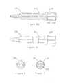
- FIG. 1shows an external side and partial section view of one embodiment of the invention.
- FIG. 2shows an external connector end view of the embodiment of the invention shown in FIG. 1 .
- FIG. 3shows an external cable end view of the embodiment of the invention shown in FIG. 1 .
- FIG. 4 ashows a section side view of a body portion of the embodiment of the invention shown in FIG. 1 .
- FIG. 4 bshows an external side view of a body portion of the embodiment of the invention shown in FIG. 1 .
- FIG. 5 ashows a side section view of an inner contact of the embodiment of the invention shown in FIG. 1 .
- FIG. 5 bshows an external side view of an inner contact of the embodiment of the invention shown in FIG. 1 .
- FIG. 6shows an external connector end view of the inner contact shown in FIGS. 5 a and 5 b.
- FIG. 7shows an external cable end view of the inner contact shown in FIGS. 5 a and 5 b.
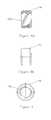
- FIG. 8 ashows a cross section view of a gasket of the embodiment of the invention shown in FIG. 1 .
- FIG. 8 bshows an external side view of a gasket of the embodiment of the invention shown in FIG. 1 .
- FIG. 9shows an external cable end view of the gasket shown in FIGS. 8 a and 8 b.
- FIG. 10shows an external side view of a connector according to one embodiment of the invention attached to a cable with heat shrink tubing applied to cover the interface between the cable and the connector.
- FIG. 1One embodiment of a crimp connector, for example a type N connector, is shown in FIG. 1 .
- the crimp connector 1has a connector end 10 ( FIG. 2 ) and a cable end 20 (FIG. 3 ).
- the specific form or connector interface of connector end 10may depend on the intended coaxial cable diameter/type and or the application the crimp connector is intended for.
- the connector end 10 of the crimp connectormay be configured with a connector interface selected to mate with any type of connector mounted on a device/cable using, for example, standard type N, BNC, SMA, DIN, UHF, CATV, EIA, or a proprietary connector interface configuration. Dimensions/configuration of the crimp connector 1 at the connector end 10 that form the desired standardized connector type are known in the art.
- a connector end 10 in a type N configurationis shown in FIGS. 1 and 2 .
- a body 30forms the outer shell of the cable end 20 .
- the body 30has a connector end annular shoulder 40 for receiving and retaining via, for example an interference fit, the connector end 10 .
- a threaded section 50is formed to mate with helical corrugations in the outer conductor of the desired coaxial cable.
- the body 30may be formed from, for example brass or other metal alloy.
- the body 30may have a corrosion resistant plating, for example, tin or chromium plating.
- a cable end shoulder 80may be added to the body 30 for seating a gasket 90 or an application of sealant, described herein below.
- a helically corrugated coaxial cablemay be prepared for attaching the crimp connector 1 by exposing an appropriate length of the cable's inner conductor and removing any outer sheath from a section of the outer conductor.
- the crimp connector 1may then be hand threaded onto the cable until the cable's outer conductor impacts upon a stop 60 that extends radially inward across the radial depth of the body 30 .
- further threadingmay partially collapse/compress the cable outer conductor corrugations into a deformation groove 70 .
- the cablemay be electrically interconnected with (outer conductor to body 30 ) and securely fixed within the connector 1 without requiring field application of solder or conductive adhesive by applying a crimp tool to the body 30 on a crimp area 100 which may correspond, for example, to the internal threaded section 50 .
- the outer diameter of the crimp area 100may be adjusted to mate with, for example, industry standard hexagonal crimp hand tools by adjusting the radius of the crimp area 100 .
- a plurality of ridges 105may be formed in the crimp area 100 .
- the depth and width of grooves between the ridges 105may be selected to adjust the compressive force, for example to be within the range of force generatable by a hand tool, required to compress/deform the internal threaded section 50 and outer conductor of the cable during the crimp operation and also to create a corresponding retentive strength of the compressed material once crimped.
- the cable's inner conductoris inserted into an inner contact 110 ( FIGS. 5 a - 7 ).
- the inner contact 110extends between the connector end 10 ( FIG. 6 ) and the cable end 20 (FIG. 7 ).
- An insulator 115may be mounted in the connector end 10 to locate the inner contact 110 coaxially spaced away from the body 30 .
- a radial barb 117 or other structure on the inner contact 110may be used to retain the inner contact 110 within the insulator 115 .
- a socket contact section 120 on the cable end 20 of the inner contact 110may be formed with a cable end 20 diameter smaller than an outer diameter of the cable inner conductor.
- a plurality of slits 130may be formed in the socket contact section 120 to allow the socket contact section 120 to easily flex and accommodate the cable inner conductor upon insertion, creating a secure electrical connection without requiring, for example, soldering or conductive adhesive.
- the inner contact 110may be formed from a spring temper material, for example beryllium copper, phosphor bronze or other metal or metal alloy with suitable spring/flex characteristics.
- the inner contact 110may be given a low contact resistance surface treatment, for example, gold or silver plating to increase conductive characteristics and negate dissimilar metal reactions with the center conductor of the cable and or other connectors.
- the appropriate length of exposed cable inner conductormay be a length that results in the inner conductor being inserted into the socket contact section 120 short of contacting a depression 140 when the outer conductor of the cable has fully seated against the stop 60 and any compression of the outer conductor into the deformation groove 70 is completed.
- the threaded section 50 of the embodiment shown in FIGS. 1-9matches a cable with double helical corrugation as described in U.S. patent application Ser. No. 10/131,747 filed Apr. 24, 2002 also assigned to Andrew Corporation and hereby incorporated by reference in its entirety.
- the double helical corrugationprovides the cable with advantageous strength, flexibility and weight characteristics.
- dual grooves that form the double helical corrugationalso increase the opportunity for moisture infiltration due to the presence of an additional groove, compared to a traditional (single) helical corrugation.
- the gasket 90may be pre-positioned on the cable outer conductor to be located against the cable end shoulder 80 to form a seal between the body 30 and the outer conductor of the cable as the crimp connector 1 is threaded onto the cable.
- a pair of threads 150one oriented for each groove, ensures that the gasket 90 fully seals against the surface of the outer conductor, to the bottom of each groove.
- the gasket 90may be formed from an elastomer, for example, neoprene, EPDM, silicone or nitrile material.
- the gasket 90may be replaced with an application of, for example, silicone or other sealant applied to the cable end shoulder and or the corresponding location on the cable outer conductor.
- heat shrink tubing 170may be applied over the body 30 and cable 180 interface as an additional environmental seal and to improve rigidity of the connection between the crimp connector 1 and the cable.
- the extended section of heat shrink tubing 170 covering the cable 180creates an extended path through which moisture must pass to infiltrate the interconnection between the body 30 and the cable 180 .
- the section of tubing over the body 30is relatively short, creating an increased opportunity for moisture infiltration.
- an outward facing radial body barb 160may be formed on the body 30 .
- the body barb 160presents an acute contact surface that the heat shrink tubing will tightly seal against/around thereby reducing the opportunity for moisture infiltration and increasing the overall rigidity of the assembly.
- the crimp connectorprovides the following advantages.
- the crimp connectorhas a limited number of components and may be cost effectively assembled with only a few manufacturing operations. Further, the crimp connector may be installed in the field, without requiring soldering or conductive adhesives, using only industry standard hand tools. Also, the crimp connector may be used with double helical corrugated cable to form a cable/connector interconnection with a high level of moisture infiltration resistance. When heat shrink tubing is applied to the crimp connector, an improved seal is created and the cable/connector interconnection has increased rigidity.
Landscapes
- Coupling Device And Connection With Printed Circuit (AREA)
- Connector Housings Or Holding Contact Members (AREA)
Abstract
Description
| Table of |
| 1 | |
| 10 | |
| 20 | |
| 30 | |
| 40 | |
| 50 | threaded |
| 60 | |
| 70 | |
| 80 | |
| 90 | |
| 100 | |
| 105 | |
| 110 | |
| 115 | |
| 117 | |
| 120 | |
| 130 | |
| 140 | |
| 150 | |
| 160 | |
| 170 | |
| 180 | cable |
Claims (19)
Priority Applications (4)
| Application Number | Priority Date | Filing Date | Title |
|---|---|---|---|
| US10/248,741US6840803B2 (en) | 2003-02-13 | 2003-02-13 | Crimp connector for corrugated cable |
| US10/249,112US6848941B2 (en) | 2003-02-13 | 2003-03-17 | Low cost, high performance cable-connector system and assembly method |
| EP04000665AEP1447881A3 (en) | 2003-02-13 | 2004-01-15 | Coaxial cable connector system and assembly method |
| CNB2004100039243ACN100399630C (en) | 2003-02-13 | 2004-02-10 | Low cost, high performance cable-connector system and assembly method |
Applications Claiming Priority (1)
| Application Number | Priority Date | Filing Date | Title |
|---|---|---|---|
| US10/248,741US6840803B2 (en) | 2003-02-13 | 2003-02-13 | Crimp connector for corrugated cable |
Related Child Applications (1)
| Application Number | Title | Priority Date | Filing Date |
|---|---|---|---|
| US10/249,112Continuation-In-PartUS6848941B2 (en) | 2003-02-13 | 2003-03-17 | Low cost, high performance cable-connector system and assembly method |
Publications (2)
| Publication Number | Publication Date |
|---|---|
| US20040161969A1 US20040161969A1 (en) | 2004-08-19 |
| US6840803B2true US6840803B2 (en) | 2005-01-11 |
Family
ID=32849388
Family Applications (1)
| Application Number | Title | Priority Date | Filing Date |
|---|---|---|---|
| US10/248,741Expired - Fee RelatedUS6840803B2 (en) | 2003-02-13 | 2003-02-13 | Crimp connector for corrugated cable |
Country Status (1)
| Country | Link |
|---|---|
| US (1) | US6840803B2 (en) |
Cited By (56)
| Publication number | Priority date | Publication date | Assignee | Title |
|---|---|---|---|---|
| US20060194474A1 (en)* | 2004-07-16 | 2006-08-31 | John Mezzalingua Associates, Inc. | Compression connector for braided coaxial cable |
| US7126064B1 (en) | 2005-08-22 | 2006-10-24 | Sami Shemtov | Connector for affixing cables within junction boxes |
| US20080057778A1 (en)* | 2006-08-29 | 2008-03-06 | Gordon Clark | Threaded connector and patch cord having a threaded connector |
| US7351101B1 (en) | 2006-08-17 | 2008-04-01 | John Mezzalingua Associates, Inc. | Compact compression connector for annular corrugated coaxial cable |
| US20080207051A1 (en)* | 2007-02-22 | 2008-08-28 | John Mezzalingua Associates, Inc. | Coaxial cable connector with independently actuated engagement of inner and outer conductors |
| US20080274643A1 (en)* | 2007-05-02 | 2008-11-06 | Shawn Chawgo | Compression Connector For Coaxial Cable |
| US20090130900A1 (en)* | 2007-11-21 | 2009-05-21 | Jens Petersen | Coaxial Cable Connector For Corrugated Cable |
| US20090197465A1 (en)* | 2007-05-02 | 2009-08-06 | John Mezzalingua Associates, Inc. | Compression connector for coaxial cable with staggered seizure of outer and center conductor |
| US20090233482A1 (en)* | 2007-05-02 | 2009-09-17 | Shawn Chawgo | Compression Connector For Coaxial Cable |
| US20090233483A1 (en)* | 2008-03-17 | 2009-09-17 | Commscope, Inc. Of North Carolina | Coaxial Cable Crimp Connector |
| US20090297102A1 (en)* | 2008-05-28 | 2009-12-03 | Adc Telecommunications, Inc. | Fiber optic cable for connectorization and method |
| US7753727B1 (en) | 2009-05-22 | 2010-07-13 | Andrew Llc | Threaded crimp coaxial connector |
| US20100233903A1 (en)* | 2009-03-10 | 2010-09-16 | Andrew Llc | Inner conductor end contacting coaxial connector and inner conductor adapter kit |
| US20100261381A1 (en)* | 2009-04-10 | 2010-10-14 | John Mezzalingua Associates, Inc. | Compression connector for coaxial cables |
| US20100261382A1 (en)* | 2009-04-10 | 2010-10-14 | John Mezzalingua Associates, Inc. | Compression coaxial cable connector with center insulator seizing mechanism |
| US20100273340A1 (en)* | 2009-04-24 | 2010-10-28 | Jan Michael Clausen | Coaxial Connector For Corrugated Cable With Corrugated Sealing |
| US7934954B1 (en) | 2010-04-02 | 2011-05-03 | John Mezzalingua Associates, Inc. | Coaxial cable compression connectors |
| US8047870B2 (en) | 2009-01-09 | 2011-11-01 | Corning Gilbert Inc. | Coaxial connector for corrugated cable |
| US8177582B2 (en) | 2010-04-02 | 2012-05-15 | John Mezzalingua Associates, Inc. | Impedance management in coaxial cable terminations |
| US8177583B2 (en) | 2007-05-02 | 2012-05-15 | John Mezzalingua Associates, Inc. | Compression connector for coaxial cable |
| US8298006B2 (en) | 2010-10-08 | 2012-10-30 | John Mezzalingua Associates, Inc. | Connector contact for tubular center conductor |
| US8328577B1 (en)* | 2011-10-15 | 2012-12-11 | Yueh Chiung Lu | Coaxial cable connector |
| US8430688B2 (en) | 2010-10-08 | 2013-04-30 | John Mezzalingua Associates, LLC | Connector assembly having deformable clamping surface |
| US8435073B2 (en) | 2010-10-08 | 2013-05-07 | John Mezzalingua Associates, LLC | Connector assembly for corrugated coaxial cable |
| US8439703B2 (en) | 2010-10-08 | 2013-05-14 | John Mezzalingua Associates, LLC | Connector assembly for corrugated coaxial cable |
| US8449325B2 (en) | 2010-10-08 | 2013-05-28 | John Mezzalingua Associates, LLC | Connector assembly for corrugated coaxial cable |
| US8458898B2 (en) | 2010-10-28 | 2013-06-11 | John Mezzalingua Associates, LLC | Method of preparing a terminal end of a corrugated coaxial cable for termination |
| US8468688B2 (en) | 2010-04-02 | 2013-06-25 | John Mezzalingua Associates, LLC | Coaxial cable preparation tools |
| US8628352B2 (en) | 2011-07-07 | 2014-01-14 | John Mezzalingua Associates, LLC | Coaxial cable connector assembly |
| US20140080346A1 (en)* | 2012-09-18 | 2014-03-20 | Yueh Chiung Lu | Coaxial Cable Connector with Multi-Contact to Ensure Establishment of Ground Loop |
| US8684763B2 (en) | 2011-06-21 | 2014-04-01 | Adc Telecommunications, Inc. | Connector with slideable retention feature and patch cord having the same |
| US20140102753A1 (en)* | 2012-10-11 | 2014-04-17 | John Mezzalingua Associates, LLC | Coaxial cable device and method involving weld connectivity |
| US20140113486A1 (en)* | 2012-10-11 | 2014-04-24 | John Mezzalingua Associates, LLC | Coaxial cable device and method involving weld and mate connectivity |
| US20140120769A1 (en)* | 2012-10-29 | 2014-05-01 | Carlisle Interconnect Technologies, Inc. | High density sealed electrical connector with multiple shielding strain relief devices |
| US20140120785A1 (en)* | 2012-10-24 | 2014-05-01 | Winchester Electronics Corporation | In-flight entertainment system for an aircraft |
| US8766110B2 (en) | 2011-10-07 | 2014-07-01 | Titeflex Corporation | Bushings, sealing devices, tubing, and methods of installing tubing |
| US20140242840A1 (en)* | 2012-10-29 | 2014-08-28 | Carlisle Interconnect Technologies, Inc. | High density sealed electrical connector with grounding contact for improved mechanical connection and shielding |
| US8845359B2 (en) | 2011-06-21 | 2014-09-30 | Tyco Electronics Uk Ltd | Connector with cable retention feature and patch cord having the same |
| US9009960B2 (en) | 2013-01-25 | 2015-04-21 | Commscope Technologies Llc | Method of manufacturing a curved transition surface of an inner contact |
| US9017102B2 (en) | 2012-02-06 | 2015-04-28 | John Mezzalingua Associates, LLC | Port assembly connector for engaging a coaxial cable and an outer conductor |
| US9024191B2 (en) | 2011-10-03 | 2015-05-05 | Commscope Technologies Llc | Strain relief for connector and cable interconnection |
| US20150144398A1 (en)* | 2013-11-26 | 2015-05-28 | Andrew Llc | Adapter for sealing cover for electrical interconnections |
| US9083113B2 (en) | 2012-01-11 | 2015-07-14 | John Mezzalingua Associates, LLC | Compression connector for clamping/seizing a coaxial cable and an outer conductor |
| US9099825B2 (en) | 2012-01-12 | 2015-08-04 | John Mezzalingua Associates, LLC | Center conductor engagement mechanism |
| US9108348B2 (en) | 2011-10-03 | 2015-08-18 | Commscope Technologies Llc | Method for molding a low pressure molded strain relief for coaxial connector interconnection |
| US9166306B2 (en) | 2010-04-02 | 2015-10-20 | John Mezzalingua Associates, LLC | Method of terminating a coaxial cable |
| US9172156B2 (en) | 2010-10-08 | 2015-10-27 | John Mezzalingua Associates, LLC | Connector assembly having deformable surface |
| US9515444B2 (en) | 2011-04-11 | 2016-12-06 | Commscope Technologies Llc | Corrugated solder pre-form and method of use |
| US9541225B2 (en) | 2013-05-09 | 2017-01-10 | Titeflex Corporation | Bushings, sealing devices, tubing, and methods of installing tubing |
| US9601867B2 (en)* | 2015-05-08 | 2017-03-21 | Qm Power, Inc. | Cord retention and moisture seal for electric motors |
| US9633765B2 (en) | 2012-10-11 | 2017-04-25 | John Mezzalingua Associates, LLC | Coaxial cable device having a helical outer conductor and method for effecting weld connectivity |
| US9633761B2 (en) | 2014-11-25 | 2017-04-25 | John Mezzalingua Associates, LLC | Center conductor tip |
| US20180062281A1 (en)* | 2015-03-19 | 2018-03-01 | Kathrein-Werke Kg | Plug connector for making solder-free contact with a coaxial cable |
| US9929481B2 (en)* | 2013-03-15 | 2018-03-27 | Rosenberger Hochfrequenztechnik Gmbh | Plug-type connector |
| US10658787B2 (en)* | 2018-03-20 | 2020-05-19 | Commscope Technologies Llc | Coaxial cable and connector assembly with pre-molded protective boot |
| US11114796B2 (en) | 2018-12-04 | 2021-09-07 | Carlisle Interconnect Technologies, Inc. | Electrical connector with modular housing for accommodating various contact layouts |
Families Citing this family (2)
| Publication number | Priority date | Publication date | Assignee | Title |
|---|---|---|---|---|
| DE102007008740B3 (en)* | 2007-02-22 | 2008-07-24 | Siemens Ag | Electrical connector has spike protection with partly metallic housing, which has cable-lateral and plug-lateral end, and dielectric material sleeve surrounds total connector |
| US7753726B2 (en)* | 2008-04-16 | 2010-07-13 | Tyco Electronics Corporation | Composite electrical connector assembly |
Citations (16)
| Publication number | Priority date | Publication date | Assignee | Title |
|---|---|---|---|---|
| US4990106A (en)* | 1989-06-12 | 1991-02-05 | John Mezzalingua Assoc. Inc. | Coaxial cable end connector |
| US5073129A (en) | 1989-06-12 | 1991-12-17 | John Mezzalingua Assoc. Inc. | Coaxial cable end connector |
| US5141451A (en)* | 1991-05-22 | 1992-08-25 | Gilbert Engineering Company, Inc. | Securement means for coaxial cable connector |
| US5154636A (en)* | 1991-01-15 | 1992-10-13 | Andrew Corporation | Self-flaring connector for coaxial cable having a helically corrugated outer conductor |
| US5281167A (en)* | 1993-05-28 | 1994-01-25 | The Whitaker Corporation | Coaxial connector for soldering to semirigid cable |
| US5334051A (en) | 1993-06-17 | 1994-08-02 | Andrew Corporation | Connector for coaxial cable having corrugated outer conductor and method of attachment |
| US5518420A (en)* | 1993-06-01 | 1996-05-21 | Spinner Gmbh Elektrotechnische Fabrik | Electrical connector for a corrugated coaxial cable |
| US5561900A (en) | 1993-05-14 | 1996-10-08 | The Whitaker Corporation | Method of attaching coaxial connector to coaxial cable |
| US5595502A (en) | 1995-08-04 | 1997-01-21 | Andrew Corporation | Connector for coaxial cable having hollow inner conductor and method of attachment |
| US5795188A (en) | 1996-03-28 | 1998-08-18 | Andrew Corporation | Connector kit for a coaxial cable, method of attachment and the resulting assembly |
| US5802710A (en)* | 1996-10-24 | 1998-09-08 | Andrew Corporation | Method of attaching a connector to a coaxial cable and the resulting assembly |
| US5877452A (en) | 1997-03-13 | 1999-03-02 | Mcconnell; David E. | Coaxial cable connector |
| US5938474A (en) | 1997-12-10 | 1999-08-17 | Radio Frequency Systems, Inc. | Connector assembly for a coaxial cable |
| US5944556A (en) | 1997-04-07 | 1999-08-31 | Andrew Corporation | Connector for coaxial cable |
| US5977484A (en)* | 1997-01-08 | 1999-11-02 | Jones; Michael G. | Low-odor dual element cable connection cover |
| US6575786B1 (en)* | 2002-01-18 | 2003-06-10 | Adc Telecommunications, Inc. | Triaxial connector and method |
- 2003
- 2003-02-13USUS10/248,741patent/US6840803B2/ennot_activeExpired - Fee Related
Patent Citations (18)
| Publication number | Priority date | Publication date | Assignee | Title |
|---|---|---|---|---|
| US5073129A (en) | 1989-06-12 | 1991-12-17 | John Mezzalingua Assoc. Inc. | Coaxial cable end connector |
| US4990106A (en)* | 1989-06-12 | 1991-02-05 | John Mezzalingua Assoc. Inc. | Coaxial cable end connector |
| US5073129B1 (en) | 1989-06-12 | 1994-02-08 | John Mezzalingua Assoc. Inc. | |
| US5154636A (en)* | 1991-01-15 | 1992-10-13 | Andrew Corporation | Self-flaring connector for coaxial cable having a helically corrugated outer conductor |
| US5141451A (en)* | 1991-05-22 | 1992-08-25 | Gilbert Engineering Company, Inc. | Securement means for coaxial cable connector |
| US5561900A (en) | 1993-05-14 | 1996-10-08 | The Whitaker Corporation | Method of attaching coaxial connector to coaxial cable |
| US6471545B1 (en) | 1993-05-14 | 2002-10-29 | The Whitaker Corporation | Coaxial connector for coaxial cable having a corrugated outer conductor |
| US5281167A (en)* | 1993-05-28 | 1994-01-25 | The Whitaker Corporation | Coaxial connector for soldering to semirigid cable |
| US5518420A (en)* | 1993-06-01 | 1996-05-21 | Spinner Gmbh Elektrotechnische Fabrik | Electrical connector for a corrugated coaxial cable |
| US5334051A (en) | 1993-06-17 | 1994-08-02 | Andrew Corporation | Connector for coaxial cable having corrugated outer conductor and method of attachment |
| US5595502A (en) | 1995-08-04 | 1997-01-21 | Andrew Corporation | Connector for coaxial cable having hollow inner conductor and method of attachment |
| US5795188A (en) | 1996-03-28 | 1998-08-18 | Andrew Corporation | Connector kit for a coaxial cable, method of attachment and the resulting assembly |
| US5802710A (en)* | 1996-10-24 | 1998-09-08 | Andrew Corporation | Method of attaching a connector to a coaxial cable and the resulting assembly |
| US5977484A (en)* | 1997-01-08 | 1999-11-02 | Jones; Michael G. | Low-odor dual element cable connection cover |
| US5877452A (en) | 1997-03-13 | 1999-03-02 | Mcconnell; David E. | Coaxial cable connector |
| US5944556A (en) | 1997-04-07 | 1999-08-31 | Andrew Corporation | Connector for coaxial cable |
| US5938474A (en) | 1997-12-10 | 1999-08-17 | Radio Frequency Systems, Inc. | Connector assembly for a coaxial cable |
| US6575786B1 (en)* | 2002-01-18 | 2003-06-10 | Adc Telecommunications, Inc. | Triaxial connector and method |
Cited By (97)
| Publication number | Priority date | Publication date | Assignee | Title |
|---|---|---|---|---|
| US7217155B2 (en) | 2004-07-16 | 2007-05-15 | John Mezzalinaqua Associates, Inc. | Compression connector for braided coaxial cable |
| US20060194474A1 (en)* | 2004-07-16 | 2006-08-31 | John Mezzalingua Associates, Inc. | Compression connector for braided coaxial cable |
| US7126064B1 (en) | 2005-08-22 | 2006-10-24 | Sami Shemtov | Connector for affixing cables within junction boxes |
| US7351101B1 (en) | 2006-08-17 | 2008-04-01 | John Mezzalingua Associates, Inc. | Compact compression connector for annular corrugated coaxial cable |
| US7712214B2 (en) | 2006-08-29 | 2010-05-11 | Adc Telecommunications, Inc. | Method of assembling a patch cord having a threaded connector |
| US20080057778A1 (en)* | 2006-08-29 | 2008-03-06 | Gordon Clark | Threaded connector and patch cord having a threaded connector |
| US7413466B2 (en) | 2006-08-29 | 2008-08-19 | Adc Telecommunications, Inc. | Threaded connector and patch cord having a threaded connector |
| US8137126B2 (en) | 2006-08-29 | 2012-03-20 | Adc Telecommunications, Inc. | Threaded connector and patch cord having a threaded connector |
| US20080233794A1 (en)* | 2006-08-29 | 2008-09-25 | Adc Telecommunications, Inc. | Threaded connector and patch cord having a threaded connector |
| US20100248530A1 (en)* | 2006-08-29 | 2010-09-30 | Adc Telecommunications, Inc. | Threaded connector and patch cord having a threaded connector |
| US20080207051A1 (en)* | 2007-02-22 | 2008-08-28 | John Mezzalingua Associates, Inc. | Coaxial cable connector with independently actuated engagement of inner and outer conductors |
| US7458851B2 (en) | 2007-02-22 | 2008-12-02 | John Mezzalingua Associates, Inc. | Coaxial cable connector with independently actuated engagement of inner and outer conductors |
| US20080274643A1 (en)* | 2007-05-02 | 2008-11-06 | Shawn Chawgo | Compression Connector For Coaxial Cable |
| US20090233482A1 (en)* | 2007-05-02 | 2009-09-17 | Shawn Chawgo | Compression Connector For Coaxial Cable |
| US7993159B2 (en) | 2007-05-02 | 2011-08-09 | John Mezzalingua Associates, Inc. | Compression connector for coaxial cable |
| US8123557B2 (en) | 2007-05-02 | 2012-02-28 | John Mezzalingua Associates, Inc. | Compression connector for coaxial cable with staggered seizure of outer and center conductor |
| US20090197465A1 (en)* | 2007-05-02 | 2009-08-06 | John Mezzalingua Associates, Inc. | Compression connector for coaxial cable with staggered seizure of outer and center conductor |
| US8007314B2 (en) | 2007-05-02 | 2011-08-30 | John Mezzalingua Associates, Inc. | Compression connector for coaxial cable |
| US8177583B2 (en) | 2007-05-02 | 2012-05-15 | John Mezzalingua Associates, Inc. | Compression connector for coaxial cable |
| US7690945B2 (en) | 2007-11-21 | 2010-04-06 | Corning Gilbert Inc. | Coaxial cable connector for corrugated cable |
| US20090130900A1 (en)* | 2007-11-21 | 2009-05-21 | Jens Petersen | Coaxial Cable Connector For Corrugated Cable |
| US20090233483A1 (en)* | 2008-03-17 | 2009-09-17 | Commscope, Inc. Of North Carolina | Coaxial Cable Crimp Connector |
| US8002580B2 (en)* | 2008-03-17 | 2011-08-23 | Andrew Llc | Coaxial cable crimp connector |
| US9678290B2 (en) | 2008-05-28 | 2017-06-13 | Commscope Technologies Llc | Fiber optic cable assembly including a connector assembly |
| US8391658B2 (en) | 2008-05-28 | 2013-03-05 | Adc Telecommunications, Inc. | Fiber optic cable with jacket embedded with reinforcing members |
| US9046658B2 (en) | 2008-05-28 | 2015-06-02 | Adc Telecommunications, Inc. | Fiber optic cable and connector assembly |
| US20090297102A1 (en)* | 2008-05-28 | 2009-12-03 | Adc Telecommunications, Inc. | Fiber optic cable for connectorization and method |
| US8047870B2 (en) | 2009-01-09 | 2011-11-01 | Corning Gilbert Inc. | Coaxial connector for corrugated cable |
| US7803018B1 (en) | 2009-03-10 | 2010-09-28 | Andrew Llc | Inner conductor end contacting coaxial connector and inner conductor adapter kit |
| US20100233903A1 (en)* | 2009-03-10 | 2010-09-16 | Andrew Llc | Inner conductor end contacting coaxial connector and inner conductor adapter kit |
| US20100261382A1 (en)* | 2009-04-10 | 2010-10-14 | John Mezzalingua Associates, Inc. | Compression coaxial cable connector with center insulator seizing mechanism |
| US8038472B2 (en) | 2009-04-10 | 2011-10-18 | John Mezzalingua Associates, Inc. | Compression coaxial cable connector with center insulator seizing mechanism |
| US20100261381A1 (en)* | 2009-04-10 | 2010-10-14 | John Mezzalingua Associates, Inc. | Compression connector for coaxial cables |
| US20100273340A1 (en)* | 2009-04-24 | 2010-10-28 | Jan Michael Clausen | Coaxial Connector For Corrugated Cable With Corrugated Sealing |
| US8113878B2 (en) | 2009-04-24 | 2012-02-14 | Corning Gilbert Inc. | Coaxial connector for corrugated cable with corrugated sealing |
| US7753727B1 (en) | 2009-05-22 | 2010-07-13 | Andrew Llc | Threaded crimp coaxial connector |
| US8177582B2 (en) | 2010-04-02 | 2012-05-15 | John Mezzalingua Associates, Inc. | Impedance management in coaxial cable terminations |
| US9166306B2 (en) | 2010-04-02 | 2015-10-20 | John Mezzalingua Associates, LLC | Method of terminating a coaxial cable |
| US8591254B1 (en) | 2010-04-02 | 2013-11-26 | John Mezzalingua Associates, LLC | Compression connector for cables |
| US8388375B2 (en) | 2010-04-02 | 2013-03-05 | John Mezzalingua Associates, Inc. | Coaxial cable compression connectors |
| US8708737B2 (en) | 2010-04-02 | 2014-04-29 | John Mezzalingua Associates, LLC | Cable connectors having a jacket seal |
| US7934954B1 (en) | 2010-04-02 | 2011-05-03 | John Mezzalingua Associates, Inc. | Coaxial cable compression connectors |
| US8956184B2 (en) | 2010-04-02 | 2015-02-17 | John Mezzalingua Associates, LLC | Coaxial cable connector |
| US8602818B1 (en) | 2010-04-02 | 2013-12-10 | John Mezzalingua Associates, LLC | Compression connector for cables |
| US8468688B2 (en) | 2010-04-02 | 2013-06-25 | John Mezzalingua Associates, LLC | Coaxial cable preparation tools |
| US8591253B1 (en) | 2010-04-02 | 2013-11-26 | John Mezzalingua Associates, LLC | Cable compression connectors |
| US8449325B2 (en) | 2010-10-08 | 2013-05-28 | John Mezzalingua Associates, LLC | Connector assembly for corrugated coaxial cable |
| US8439703B2 (en) | 2010-10-08 | 2013-05-14 | John Mezzalingua Associates, LLC | Connector assembly for corrugated coaxial cable |
| US9276363B2 (en) | 2010-10-08 | 2016-03-01 | John Mezzalingua Associates, LLC | Connector assembly for corrugated coaxial cable |
| US8435073B2 (en) | 2010-10-08 | 2013-05-07 | John Mezzalingua Associates, LLC | Connector assembly for corrugated coaxial cable |
| US9172156B2 (en) | 2010-10-08 | 2015-10-27 | John Mezzalingua Associates, LLC | Connector assembly having deformable surface |
| US8430688B2 (en) | 2010-10-08 | 2013-04-30 | John Mezzalingua Associates, LLC | Connector assembly having deformable clamping surface |
| US8298006B2 (en) | 2010-10-08 | 2012-10-30 | John Mezzalingua Associates, Inc. | Connector contact for tubular center conductor |
| US8458898B2 (en) | 2010-10-28 | 2013-06-11 | John Mezzalingua Associates, LLC | Method of preparing a terminal end of a corrugated coaxial cable for termination |
| US9515444B2 (en) | 2011-04-11 | 2016-12-06 | Commscope Technologies Llc | Corrugated solder pre-form and method of use |
| US9853408B2 (en) | 2011-04-11 | 2017-12-26 | Commscope Technologies Llc | Corrugated solder pre-form and method of use |
| US9214771B2 (en) | 2011-06-01 | 2015-12-15 | John Mezzalingua Associates, LLC | Connector for a cable |
| US9214759B2 (en) | 2011-06-21 | 2015-12-15 | Adc Telecommunications, Inc. | Connector with slideable retention feature and patch cord having the same |
| US8845359B2 (en) | 2011-06-21 | 2014-09-30 | Tyco Electronics Uk Ltd | Connector with cable retention feature and patch cord having the same |
| US9413154B2 (en) | 2011-06-21 | 2016-08-09 | Commscope Connectivity Uk Limited | Connector with cable retention feature and patch cord having the same |
| US8684763B2 (en) | 2011-06-21 | 2014-04-01 | Adc Telecommunications, Inc. | Connector with slideable retention feature and patch cord having the same |
| US8628352B2 (en) | 2011-07-07 | 2014-01-14 | John Mezzalingua Associates, LLC | Coaxial cable connector assembly |
| US9889586B2 (en) | 2011-10-03 | 2018-02-13 | Commscope Technologies Llc | Low pressure molded strain relief for coaxial connector interconnection |
| US9024191B2 (en) | 2011-10-03 | 2015-05-05 | Commscope Technologies Llc | Strain relief for connector and cable interconnection |
| US9108348B2 (en) | 2011-10-03 | 2015-08-18 | Commscope Technologies Llc | Method for molding a low pressure molded strain relief for coaxial connector interconnection |
| US9975287B2 (en) | 2011-10-03 | 2018-05-22 | Commscope Technologies Llc | Strain relief for connector and cable interconnection |
| US8766110B2 (en) | 2011-10-07 | 2014-07-01 | Titeflex Corporation | Bushings, sealing devices, tubing, and methods of installing tubing |
| US8328577B1 (en)* | 2011-10-15 | 2012-12-11 | Yueh Chiung Lu | Coaxial cable connector |
| US9083113B2 (en) | 2012-01-11 | 2015-07-14 | John Mezzalingua Associates, LLC | Compression connector for clamping/seizing a coaxial cable and an outer conductor |
| US9099825B2 (en) | 2012-01-12 | 2015-08-04 | John Mezzalingua Associates, LLC | Center conductor engagement mechanism |
| US9017102B2 (en) | 2012-02-06 | 2015-04-28 | John Mezzalingua Associates, LLC | Port assembly connector for engaging a coaxial cable and an outer conductor |
| US20140080346A1 (en)* | 2012-09-18 | 2014-03-20 | Yueh Chiung Lu | Coaxial Cable Connector with Multi-Contact to Ensure Establishment of Ground Loop |
| US8753137B2 (en)* | 2012-09-18 | 2014-06-17 | Yueh Chiung Lu | Coaxial cable connector with multi-contact to ensure establishment of ground loop |
| US9384872B2 (en)* | 2012-10-11 | 2016-07-05 | John Mezzalingua Associates, LLC | Coaxial cable device and method involving weld connectivity |
| US9633765B2 (en) | 2012-10-11 | 2017-04-25 | John Mezzalingua Associates, LLC | Coaxial cable device having a helical outer conductor and method for effecting weld connectivity |
| US20140113486A1 (en)* | 2012-10-11 | 2014-04-24 | John Mezzalingua Associates, LLC | Coaxial cable device and method involving weld and mate connectivity |
| US9312609B2 (en)* | 2012-10-11 | 2016-04-12 | John Mezzalingua Associates, LLC | Coaxial cable device and method involving weld and mate connectivity |
| US20140102753A1 (en)* | 2012-10-11 | 2014-04-17 | John Mezzalingua Associates, LLC | Coaxial cable device and method involving weld connectivity |
| US20140120785A1 (en)* | 2012-10-24 | 2014-05-01 | Winchester Electronics Corporation | In-flight entertainment system for an aircraft |
| US9306312B2 (en)* | 2012-10-29 | 2016-04-05 | Carlisle Interconnect Technologies, Inc. | High density sealed electrical connector with multiple shielding strain relief devices |
| US20140120769A1 (en)* | 2012-10-29 | 2014-05-01 | Carlisle Interconnect Technologies, Inc. | High density sealed electrical connector with multiple shielding strain relief devices |
| US9306333B2 (en)* | 2012-10-29 | 2016-04-05 | Carlisle Interconnect Technologies, Inc. | High density sealed electrical connector with grounding contact for improved mechanical connection and shielding |
| US20140242840A1 (en)* | 2012-10-29 | 2014-08-28 | Carlisle Interconnect Technologies, Inc. | High density sealed electrical connector with grounding contact for improved mechanical connection and shielding |
| US9419351B2 (en) | 2013-01-25 | 2016-08-16 | Commscope Technologies Llc | Curved transition surface inner contact |
| US9009960B2 (en) | 2013-01-25 | 2015-04-21 | Commscope Technologies Llc | Method of manufacturing a curved transition surface of an inner contact |
| US9929481B2 (en)* | 2013-03-15 | 2018-03-27 | Rosenberger Hochfrequenztechnik Gmbh | Plug-type connector |
| US9541225B2 (en) | 2013-05-09 | 2017-01-10 | Titeflex Corporation | Bushings, sealing devices, tubing, and methods of installing tubing |
| US10404048B2 (en)* | 2013-11-26 | 2019-09-03 | Commscope Technologies Llc | Adapter for sealing cover for electrical interconnections |
| US20150144398A1 (en)* | 2013-11-26 | 2015-05-28 | Andrew Llc | Adapter for sealing cover for electrical interconnections |
| US9633761B2 (en) | 2014-11-25 | 2017-04-25 | John Mezzalingua Associates, LLC | Center conductor tip |
| US9853372B2 (en) | 2014-11-25 | 2017-12-26 | John Mezzalingua Associates, LLC | Center conductor tip |
| US20180062281A1 (en)* | 2015-03-19 | 2018-03-01 | Kathrein-Werke Kg | Plug connector for making solder-free contact with a coaxial cable |
| US10128586B2 (en)* | 2015-03-19 | 2018-11-13 | Kathrein-Werke Kg | Plug connector for making solder-free contact with a coaxial cable |
| US9601867B2 (en)* | 2015-05-08 | 2017-03-21 | Qm Power, Inc. | Cord retention and moisture seal for electric motors |
| US10658787B2 (en)* | 2018-03-20 | 2020-05-19 | Commscope Technologies Llc | Coaxial cable and connector assembly with pre-molded protective boot |
| US11114796B2 (en) | 2018-12-04 | 2021-09-07 | Carlisle Interconnect Technologies, Inc. | Electrical connector with modular housing for accommodating various contact layouts |
| US11721929B2 (en) | 2018-12-04 | 2023-08-08 | Carlisle Interconnect Technologies, Inc. | Electrical connector with modular housing for accommodating various contact layouts |
Also Published As
| Publication number | Publication date |
|---|---|
| US20040161969A1 (en) | 2004-08-19 |
Similar Documents
| Publication | Publication Date | Title |
|---|---|---|
| US6840803B2 (en) | Crimp connector for corrugated cable | |
| US6848941B2 (en) | Low cost, high performance cable-connector system and assembly method | |
| US6939169B2 (en) | Axial compression electrical connector | |
| US7448906B1 (en) | Hollow inner conductor contact for coaxial cable connector | |
| FI103841B (en) | Flexible connector for coaxial cables with threaded outer conductor | |
| US9327371B2 (en) | Enhanced coaxial connector continuity | |
| EP2067215B1 (en) | Right-angled coaxial cable connector | |
| US6817897B2 (en) | End connector for coaxial cable | |
| US8585415B2 (en) | Shielding braid termination for a shielded electrical connector | |
| US5352134A (en) | RF shielded coaxial cable connector | |
| US8062044B2 (en) | CATV port terminator with contact-enhancing ground insert | |
| US7972175B2 (en) | Coaxial cable connector with threaded post | |
| US6790081B2 (en) | Sealed coaxial cable connector and related method | |
| AU674245B2 (en) | Connector for coaxial cable having corrugated outer conductor and method of attachment | |
| US6019615A (en) | Construction of and method of processing end portion of shielded cable | |
| US20130171869A1 (en) | Coaxial Connector with Grommet Biasing for Enhanced Continuity | |
| EP3832811B1 (en) | Coaxial cable assemblies having pinching and gripping elements | |
| US20230387614A1 (en) | Nut seal assembly for coaxial cable system components that provides a mechanically secure waterproof seal | |
| JPS59134577A (en) | Solderless connector for semirigid coaxial cable | |
| JP4336819B2 (en) | Triple coaxial cable crimping structure | |
| CA2556115A1 (en) | Indoor/outdoor coaxial cable connector |
Legal Events
| Date | Code | Title | Description |
|---|---|---|---|
| AS | Assignment | Owner name:ANDREW CORPORATION, ILLINOIS Free format text:ASSIGNMENT OF ASSIGNORS INTEREST;ASSIGNORS:WLOS, JAMES;KRABEC, JAMES;REEL/FRAME:013427/0172 Effective date:20030212 | |
| AS | Assignment | Owner name:BANK OF AMERICA, N.A., AS ADMINISTRATIVE AGENT, CA Free format text:SECURITY AGREEMENT;ASSIGNORS:COMMSCOPE, INC. OF NORTH CAROLINA;ALLEN TELECOM, LLC;ANDREW CORPORATION;REEL/FRAME:020362/0241 Effective date:20071227 Owner name:BANK OF AMERICA, N.A., AS ADMINISTRATIVE AGENT,CAL Free format text:SECURITY AGREEMENT;ASSIGNORS:COMMSCOPE, INC. OF NORTH CAROLINA;ALLEN TELECOM, LLC;ANDREW CORPORATION;REEL/FRAME:020362/0241 Effective date:20071227 | |
| FPAY | Fee payment | Year of fee payment:4 | |
| AS | Assignment | Owner name:ANDREW LLC, NORTH CAROLINA Free format text:CHANGE OF NAME;ASSIGNOR:ANDREW CORPORATION;REEL/FRAME:021763/0469 Effective date:20080827 | |
| AS | Assignment | Owner name:ANDREW LLC (F/K/A ANDREW CORPORATION), NORTH CAROL Free format text:PATENT RELEASE;ASSIGNOR:BANK OF AMERICA, N.A., AS ADMINISTRATIVE AGENT;REEL/FRAME:026039/0005 Effective date:20110114 Owner name:ALLEN TELECOM LLC, NORTH CAROLINA Free format text:PATENT RELEASE;ASSIGNOR:BANK OF AMERICA, N.A., AS ADMINISTRATIVE AGENT;REEL/FRAME:026039/0005 Effective date:20110114 Owner name:COMMSCOPE, INC. OF NORTH CAROLINA, NORTH CAROLINA Free format text:PATENT RELEASE;ASSIGNOR:BANK OF AMERICA, N.A., AS ADMINISTRATIVE AGENT;REEL/FRAME:026039/0005 Effective date:20110114 | |
| AS | Assignment | Owner name:JPMORGAN CHASE BANK, N.A., AS COLLATERAL AGENT, NE Free format text:SECURITY AGREEMENT;ASSIGNORS:ALLEN TELECOM LLC, A DELAWARE LLC;ANDREW LLC, A DELAWARE LLC;COMMSCOPE, INC. OF NORTH CAROLINA, A NORTH CAROLINA CORPORATION;REEL/FRAME:026276/0363 Effective date:20110114 | |
| AS | Assignment | Owner name:JPMORGAN CHASE BANK, N.A., AS COLLATERAL AGENT, NE Free format text:SECURITY AGREEMENT;ASSIGNORS:ALLEN TELECOM LLC, A DELAWARE LLC;ANDREW LLC, A DELAWARE LLC;COMMSCOPE, INC OF NORTH CAROLINA, A NORTH CAROLINA CORPORATION;REEL/FRAME:026272/0543 Effective date:20110114 | |
| REMI | Maintenance fee reminder mailed | ||
| LAPS | Lapse for failure to pay maintenance fees | ||
| STCH | Information on status: patent discontinuation | Free format text:PATENT EXPIRED DUE TO NONPAYMENT OF MAINTENANCE FEES UNDER 37 CFR 1.362 | |
| FP | Lapsed due to failure to pay maintenance fee | Effective date:20130111 | |
| AS | Assignment | Owner name:ANDREW LLC, NORTH CAROLINA Free format text:RELEASE BY SECURED PARTY;ASSIGNOR:JPMORGAN CHASE BANK, N.A.;REEL/FRAME:048840/0001 Effective date:20190404 Owner name:ALLEN TELECOM LLC, ILLINOIS Free format text:RELEASE BY SECURED PARTY;ASSIGNOR:JPMORGAN CHASE BANK, N.A.;REEL/FRAME:048840/0001 Effective date:20190404 Owner name:COMMSCOPE, INC. OF NORTH CAROLINA, NORTH CAROLINA Free format text:RELEASE BY SECURED PARTY;ASSIGNOR:JPMORGAN CHASE BANK, N.A.;REEL/FRAME:048840/0001 Effective date:20190404 Owner name:REDWOOD SYSTEMS, INC., NORTH CAROLINA Free format text:RELEASE BY SECURED PARTY;ASSIGNOR:JPMORGAN CHASE BANK, N.A.;REEL/FRAME:048840/0001 Effective date:20190404 Owner name:COMMSCOPE TECHNOLOGIES LLC, NORTH CAROLINA Free format text:RELEASE BY SECURED PARTY;ASSIGNOR:JPMORGAN CHASE BANK, N.A.;REEL/FRAME:048840/0001 Effective date:20190404 Owner name:COMMSCOPE, INC. OF NORTH CAROLINA, NORTH CAROLINA Free format text:RELEASE BY SECURED PARTY;ASSIGNOR:JPMORGAN CHASE BANK, N.A.;REEL/FRAME:049260/0001 Effective date:20190404 Owner name:COMMSCOPE TECHNOLOGIES LLC, NORTH CAROLINA Free format text:RELEASE BY SECURED PARTY;ASSIGNOR:JPMORGAN CHASE BANK, N.A.;REEL/FRAME:049260/0001 Effective date:20190404 Owner name:ALLEN TELECOM LLC, ILLINOIS Free format text:RELEASE BY SECURED PARTY;ASSIGNOR:JPMORGAN CHASE BANK, N.A.;REEL/FRAME:049260/0001 Effective date:20190404 Owner name:REDWOOD SYSTEMS, INC., NORTH CAROLINA Free format text:RELEASE BY SECURED PARTY;ASSIGNOR:JPMORGAN CHASE BANK, N.A.;REEL/FRAME:049260/0001 Effective date:20190404 Owner name:ANDREW LLC, NORTH CAROLINA Free format text:RELEASE BY SECURED PARTY;ASSIGNOR:JPMORGAN CHASE BANK, N.A.;REEL/FRAME:049260/0001 Effective date:20190404 |