US6840770B2 - Expandable polymer dental implant and method of use - Google Patents
Expandable polymer dental implant and method of useDownload PDFInfo
- Publication number
- US6840770B2 US6840770B2US10/292,182US29218202AUS6840770B2US 6840770 B2US6840770 B2US 6840770B2US 29218202 AUS29218202 AUS 29218202AUS 6840770 B2US6840770 B2US 6840770B2
- Authority
- US
- United States
- Prior art keywords
- implant
- sheath
- abutment
- jawbone
- prosthesis
- Prior art date
- Legal status (The legal status is an assumption and is not a legal conclusion. Google has not performed a legal analysis and makes no representation as to the accuracy of the status listed.)
- Expired - Fee Related, expires
Links
- 238000000034methodMethods0.000titleclaimsabstractdescription34
- 229920000642polymerPolymers0.000titleclaimsabstractdescription33
- 239000004053dental implantSubstances0.000titleclaimsabstractdescription24
- 239000007943implantSubstances0.000claimsabstractdescription181
- 238000003780insertionMethods0.000claimsabstractdescription27
- 230000037431insertionEffects0.000claimsabstractdescription27
- 210000001519tissueAnatomy0.000claimsdescription19
- RTAQQCXQSZGOHL-UHFFFAOYSA-NTitaniumChemical compound[Ti]RTAQQCXQSZGOHL-UHFFFAOYSA-N0.000claimsdescription6
- 239000010936titaniumSubstances0.000claimsdescription6
- 229910052719titaniumInorganic materials0.000claimsdescription6
- -1PolyethylenePolymers0.000claimsdescription5
- 238000002360preparation methodMethods0.000claimsdescription3
- 239000004743PolypropyleneSubstances0.000claimsdescription2
- 230000008878couplingEffects0.000claimsdescription2
- 238000010168coupling processMethods0.000claimsdescription2
- 238000005859coupling reactionMethods0.000claimsdescription2
- 238000005553drillingMethods0.000claimsdescription2
- 229920001155polypropylenePolymers0.000claimsdescription2
- 229920003225polyurethane elastomerPolymers0.000claimsdescription2
- 238000010079rubber tappingMethods0.000claimsdescription2
- 239000004698PolyethyleneSubstances0.000claims2
- 229910045601alloyInorganic materials0.000claims2
- 239000000956alloySubstances0.000claims2
- 229920000573polyethylenePolymers0.000claims2
- 239000010935stainless steelSubstances0.000claims1
- 229910001220stainless steelInorganic materials0.000claims1
- 210000000988bone and boneAnatomy0.000description27
- 238000009434installationMethods0.000description12
- 210000001847jawAnatomy0.000description9
- 230000018984masticationEffects0.000description9
- 238000010077masticationMethods0.000description9
- 239000012528membraneSubstances0.000description9
- 230000003239periodontal effectEffects0.000description9
- 238000013461designMethods0.000description8
- 239000000463materialSubstances0.000description8
- 208000028169periodontal diseaseDiseases0.000description7
- 230000000295complement effectEffects0.000description6
- 238000007796conventional methodMethods0.000description6
- 229910001069Ti alloyInorganic materials0.000description5
- 208000008312Tooth LossDiseases0.000description4
- 230000006835compressionEffects0.000description4
- 238000007906compressionMethods0.000description4
- 239000007787solidSubstances0.000description4
- 238000012546transferMethods0.000description4
- 210000002808connective tissueAnatomy0.000description3
- 201000010099diseaseDiseases0.000description3
- 208000037265diseases, disorders, signs and symptomsDiseases0.000description3
- 230000000694effectsEffects0.000description3
- 229920001903high density polyethylenePolymers0.000description3
- 239000004700high-density polyethyleneSubstances0.000description3
- 238000012986modificationMethods0.000description3
- 230000004048modificationEffects0.000description3
- 201000001245periodontitisDiseases0.000description3
- 230000008569processEffects0.000description3
- 230000004044responseEffects0.000description3
- 230000002441reversible effectEffects0.000description3
- 206010061218InflammationDiseases0.000description2
- 230000008901benefitEffects0.000description2
- 239000000560biocompatible materialSubstances0.000description2
- 230000005540biological transmissionEffects0.000description2
- 230000007423decreaseEffects0.000description2
- 210000003298dental enamelAnatomy0.000description2
- 210000004268dentinAnatomy0.000description2
- 208000007565gingivitisDiseases0.000description2
- 238000000227grindingMethods0.000description2
- 208000015181infectious diseaseDiseases0.000description2
- 230000004054inflammatory processEffects0.000description2
- 230000003278mimic effectEffects0.000description2
- 238000003825pressingMethods0.000description2
- 230000000638stimulationEffects0.000description2
- 208000008822AnkylosisDiseases0.000description1
- 241000894006BacteriaSpecies0.000description1
- 241001133184Colletotrichum agavesSpecies0.000description1
- 208000006558Dental CalculusDiseases0.000description1
- 206010023198Joint ankylosisDiseases0.000description1
- 241000208125NicotianaSpecies0.000description1
- 235000002637Nicotiana tabacumNutrition0.000description1
- 239000004699Ultra-high molecular weight polyethyleneSubstances0.000description1
- 239000006096absorbing agentSubstances0.000description1
- PNEYBMLMFCGWSK-UHFFFAOYSA-Naluminium oxideInorganic materials[O-2].[O-2].[O-2].[Al+3].[Al+3]PNEYBMLMFCGWSK-UHFFFAOYSA-N0.000description1
- 238000004873anchoringMethods0.000description1
- 210000001367arteryAnatomy0.000description1
- 230000015572biosynthetic processEffects0.000description1
- 230000000740bleeding effectEffects0.000description1
- 239000000919ceramicSubstances0.000description1
- 230000001055chewing effectEffects0.000description1
- 238000010276constructionMethods0.000description1
- 238000011109contaminationMethods0.000description1
- 229910052593corundumInorganic materials0.000description1
- 230000006378damageEffects0.000description1
- 239000003479dental cementSubstances0.000description1
- 230000001687destabilizationEffects0.000description1
- 238000011161developmentMethods0.000description1
- 206010012601diabetes mellitusDiseases0.000description1
- 239000003814drugSubstances0.000description1
- 229940079593drugDrugs0.000description1
- 238000000605extractionMethods0.000description1
- 208000024693gingival diseaseDiseases0.000description1
- 230000035876healingEffects0.000description1
- 238000002513implantationMethods0.000description1
- 210000003041ligamentAnatomy0.000description1
- 230000007774longtermEffects0.000description1
- 230000014759maintenance of locationEffects0.000description1
- 210000004373mandibleAnatomy0.000description1
- 230000013011matingEffects0.000description1
- 210000002050maxillaAnatomy0.000description1
- 238000002483medicationMethods0.000description1
- 229910052751metalInorganic materials0.000description1
- 239000002184metalSubstances0.000description1
- 229910001092metal group alloyInorganic materials0.000description1
- 210000005036nerveAnatomy0.000description1
- 238000010883osseointegrationMethods0.000description1
- 230000000149penetrating effectEffects0.000description1
- 235000003784poor nutritionNutrition0.000description1
- 230000035935pregnancyEffects0.000description1
- 230000001737promoting effectEffects0.000description1
- 230000000717retained effectEffects0.000description1
- 230000035939shockEffects0.000description1
- 210000004872soft tissueAnatomy0.000description1
- 230000000087stabilizing effectEffects0.000description1
- 229910001256stainless steel alloyInorganic materials0.000description1
- 239000000126substanceSubstances0.000description1
- 230000003319supportive effectEffects0.000description1
- 210000000332tooth crownAnatomy0.000description1
- 229920000785ultra high molecular weight polyethylenePolymers0.000description1
- 210000003462veinAnatomy0.000description1
- 229910001845yogo sapphireInorganic materials0.000description1
Images


Classifications
- A—HUMAN NECESSITIES
- A61—MEDICAL OR VETERINARY SCIENCE; HYGIENE
- A61C—DENTISTRY; APPARATUS OR METHODS FOR ORAL OR DENTAL HYGIENE
- A61C8/00—Means to be fixed to the jaw-bone for consolidating natural teeth or for fixing dental prostheses thereon; Dental implants; Implanting tools
- A61C8/0018—Means to be fixed to the jaw-bone for consolidating natural teeth or for fixing dental prostheses thereon; Dental implants; Implanting tools characterised by the shape
- A61C8/0033—Expandable implants; Implants with extendable elements
Definitions
- This inventiongenerally relates to dental implants and methods for installing such implants.
- a tooth 10consists of a central pulp 12 that communicates with arteries 14 , veins 16 , and nerves 18 . This pulp 12 is surrounded by a calcareous substance known as dentin 20 .
- the teethproject from sockets 22 , or alveoli dentalis, in the alveolar bone 31 of the maxillae (upper jaw) or mandible (lower jaw).
- Each socket 22is a depression in the bone of the jaw lined by a connective tissue known as the periodontal membrane 24 .
- the portion of the tooth 10 that actually fits into the socket 22is formed into one or more roots 26 .
- the root 26is joined to the periodontal membrane 24 and held into the socket 22 by a calcified connective tissue known as the cementum 28 .
- the periodontal membrane 24serves as a “shock absorber” during the mastication (chewing) process.
- the projecting portion of a tooth 10known as the crown 11 , comprises grinding surfaces and is covered by another calcified connective tissue known as enamel 30 .
- the gums 32cover the base of the crown 11 and project between adjacent surfaces of the teeth 10 .
- Normal, healthy gum tissue 32serves to anchor teeth in place, as illustrated in FIG. 2 .
- Gum diseaseor periodontal disease, is an inflammation or infection of the gingival tissue. Periodontal disease is caused by a sticky film of bacteria, called plaque. Over time, plaque hardens into calculus (tartar).
- periodontitisIf left untreated, the disease spreads to other supporting structures including alveolar bone 31 , producing a more advanced stage of periodontal disease known as periodontitis.
- Periodontitisresults in the destruction of alveolar bone 31 and the periodontal membrane 24 .
- This stageis characterized by the gums 32 receding or pulling away from the teeth, resulting in the formation of pockets between the teeth and gums 32 .
- Periodontal diseaseis a major cause of tooth loss.
- the most common type of implantis endosseous, in which a screw or similar device is inserted beneath the jawbone.
- the deviceserves to mimic a root structure and protrudes through the gum to hold a prosthesis.
- a subperiosteal implantcan be placed on top of the jaw with the metal framework's posts protruding through the gum to hold the prosthesis.
- a conventional prior art endosteal implant system 100typically comprises an implant 110 , an inserting device 120 , a closure screw 130 , and an abutment 140 adapted to receive a dental prosthesis 150 .
- Conventional implants 110are cylindrically-shaped members commonly made of rigid, non-expandable biocompatible materials, e.g., a metallic alloy (e.g., titanium alloy) or ceramic (e.g., Al 2 O 3 ).
- a metallic alloye.g., titanium alloy
- ceramice.g., Al 2 O 3
- the materialcan also permit osteo ingrowth (growth of bony tissue), also known as ankylosis, into the implant 110 .
- the implant 110may be of a hollow or solid nature. A hollow nature further encourages osteo ingrowth into the implant 110 .
- the top portion of the implant 110protrudes above the gum line and is adapted to receive the closure screw 130 and the abutment 140 .
- the implant 110may additionally contain holes penetrating the wall of the implant to further promote osteo ingrowth.
- the inserting device 120is a tool adapted to couple the implant 110 and aid in the insertion of the implant 110 within the jawbone 160 .
- the closure screw 130is a screw adapted to fit within the top portion of the implant 110 .
- the closure screw 130serves to cover and protect the top portion of the implant 110 after insertion into the jawbone 160 and prior to attachment of the abutment 140 .
- the abutment 140is adapted to fit within the top portion of the implant 110 .
- the abutment 140serves to permit attachment of a dental prosthesis 150 .
- the system 110is employed in a two-part procedure.
- the siteis prepared for the insertion of the implant 110 by conventional techniques.
- the implant 110is then inserted into a predrilled hole 170 (represented by phantom lines in FIGS. 5A-5D ) within the jawbone 160 by using the inserting device 120 to screw (represented by arrow in FIG. 5A ) the implant 110 into the jawbone 160 (e.g., with the aid of a ratchet).
- the inserted implant 110is shown in FIG. 5 B.
- the closure screw 130is then screwed (represented by arrow in FIG. 5B ) into the top portion of the implant 110 .
- the first part of the procedureis then complete.
- the second part of the procedureis performed desirably at least several weeks later. This waiting period permits time for osteo (bone) ingrowth into the implant 110 . This process however does not reestablish the periodontal membrane/ligament that was destroyed as a result of the tooth loss.
- the contact between the implant and the boneis a rigid connection with no dampening effect.
- the closure screw 130is removed (not shown).
- the abutment 140is screwed (represented by arrow in FIG. 5C ) into the top portion of the implant 110 .
- a conventional dental prosthesis 150is attached to the abutment 140 using conventional techniques.
- Titanium and suitable titanium alloysare orders of magnitude higher in stiffness than human bone, and therefore dental implants formed from such materials transmit most of the forces of mastication. If the implants are cylindrical, the force is predominantly transmitted through the implant to the opposite end, and little or no force is transmitted laterally. Addition of threads can transmit some of the forces of mastication laterally.
- implants of this designtransmit insufficient lateral forces to bone or tissue surrounding the lateral surfaces of the implant and most of the forces are borne by the bone or tissue in-line with the longitudinal or force axis of the implant. This can lead to a phenomenon known as stress shielding of the surrounding bone.
- Story(U.S. Publication 2001/0000486) describes a dental implant having a force distribution shell to reduce stress shielding.
- the device according to Storyis composed of a metallic core surrounded by a polymeric shell with a modulus of elasticity lower than the metallic core, in order to transfer more of the forces of mastication to surrounding bone tissue.
- Storyteaches a cylindrical implant, which may not transfer a sufficient amount of force to prevent stress-shielding.
- the device as described by Storyis a single implant constructed of two materials. This construction does not allow the surgeon to create a significant compression fit that will sustain the initial mastication forces required for immediate loading.
- the separate component systemallows the surgeon to create a very secure compression fit between the implant and surrounding bone tissue that will sustain these immediate load forces.
- the present inventionprovides improved dental implant systems and methods of use.
- the systems and methods according to the present inventionutilize an implant system with two discrete components that are tapered and designed for dynamic response and immediate load bearing.
- the first componentis an expandable polymer sheath suitable for placement within a jawbone.
- the sheathserves as an artificial periodontal membrane.
- the second componentis a rigid implant that is inserted within the polymer sheath and causes expansion of the polymer sheath when fitted within the sheath.
- An abutmentis provided to couple the rigid implant and permits attachment of a dental prosthesis.
- Both componentsare tapered to provide for lateral transfer of loading forces onto the surrounding bone.
- the dental prosthesisis adapted to be used for a single tooth and/or to extend as a bridge over a gap.
- the systems and methodsalso provide for the ability to post-operatively remove the implant in the event that modifications need to be made.
- prior art or traditional metallic implant removalis very difficult due to osteo in-growth; once removed the prior art replacement requires another waiting period for proper in-growth to take place as well as healing from the removal.
- FIG. 1is a sectional view of a normal human tooth.
- FIG. 2is a sectional view, with portions removed, of normal, healthy teeth and gums.
- FIG. 3is a view similar to that shown in FIG. 2 and further illustrating the effects of periodontitis on the teeth and gums.
- FIG. 4is an exploded perspective view of a prior art dental implant system.
- FIGS. 5A-5Dare schematic perspective views of a lower human jawbone illustratating the use of the components of the prior art system shown in FIG. 4 .
- FIG. 6Ais a disassembled side view of a dental implant system incorporating features of the invention.
- FIG. 6Bis cut-away view of a dental implant system incorporating features of the invention.
- FIG. 6Cis a cut-away view of another embodiment of the dental implant system incorporating features of the invention.
- FIG. 6D(prior patent) is a perspective view of a portion of a lower human jawbone, showing, in an exploded view, an alternative dental implant system incorporating features of the invention.
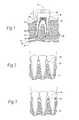
- FIGS. 7A-7Care side sectional views of a human jawbone showing the expansion of the polymer sheath component of the system shown in FIG. 6A upon insertion of the implant component into the jawbone.
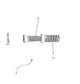
- FIG. 8is a side perspective view of a portion of a lower human jawbone showing the insertion of the polymer sheath component of the system shown in FIG. 6A into the jawbone.
- FIG. 9is a view similar to FIG. 8 showing the polymer sheath inserted into the jawbone.
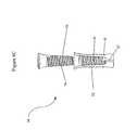
- FIG. 10is a view similar to FIG. 9 showing the insertion of the implant component of the system shown in FIG. 6 into the polymer sheath.
- FIG. 11is a view similar to FIG. 10 showing the implant inserted into the polymer sheath.
- FIG. 12is a view similar to FIG. 11 showing the coupling of the abutment component of the system shown in FIG. 6 with the implant.
- FIG. 13is a view similar to FIG. 12 showing the abutment component coupled to the implant.
- FIG. 14is a view similar to FIG. 13 showing a dental prosthesis attached to the abutment.
- FIGS. 15A and 15Bare front perspective views of a lower human jaw bone having a gap of missing teeth and further showing the use of the system shown FIG. 6A in a procedure for the insertion of a dental bridge to fill the gap.
- FIGS. 16A and 16Bare front perspective views of a lower human jaw bone having a gap of missing teeth and further showing the use of the system shown FIG. 6A in an alternative procedure for the insertion of a dental bridge.
- FIGS. 17A and 17Bare front perspective views of a lower human jaw bone having a gap of missing teeth and further showing the use of the system shown FIG. 6A in an another alternative procedure for the insertion of a dental bridge.
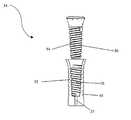
- FIG. 6Ashows a dental implant system 34 suitable for an endosteal implant into a jawbone.
- the systemcomprises a tapered expandable polymer sheath 35 , a tapered implant 36 , and an abutment 42 permitting the attachment of a dental prosthesis (not shown).
- These componentsare designed and constructed to form a system that provides for dynamic response and immediate load bearing of the implant after its installation. Details of each of these system components will now be described in detail.
- the system 34provides an expandable polymer sheath 35 , tapered, more particularly having a Morse taper and/or a taper of approximately 2-3 degrees, where the inside diameter of the sheath decreases from top to bottom, and which is illustrated in FIG. 6 A.
- the sheath 35is designed, constructed, and configured to receive an implant 36 .
- the design of the interior of the sheathis complementary to the exterior of the implant, as shown in FIGS. 6B and 6C .
- FIGS. 6B and 6Care disassembled views of the system with cut-away views of the polymer sheaths. For example, if the exterior of the implant has threads 54 , as shown in FIG. 6B , the interior of the sheath contains complementary threads 52 or grooves to guide the implant down the sheath in a predetermined manner.
- the exterior of the sheathmay be cylindrical or tapered. It may also have threading 38 to assist in installing and holding the sheath in place. This exterior threading may have the reverse orientation to the interior threading, such that installation of the implant into the sheath does not drive the sheath deeper into the jaw when resistance is met. Alternatively, the sheath may have ribbing, as shown in FIG. 6C , that prevents the sheath from being driven deeper into the jaw during installation of the implant.
- the sheathalso functions as an artificial periodontal membrane, i.e., the sheath 35 mimics the periodontal membrane by performing a like cushioning function.
- the sheath 35is a hollow conical section or tapered body having a closed bottom end portion and an open top end portion.
- the open top portionis designed, constructed, and configured to receive the implant 36 .
- the bottom endalso contains a drive feature 37 that functions to drive or turn the sheath into the bone with the appropriate drive tool during installation.
- the drive featurecan also be used to remove the sheath by unscrewing it from the bone.
- the drive featurecan be shortened, as in FIG. 6B , or elongated, as in FIG. 6 C.
- the expandable nature of the sheath 35permits it to receive the implant 36 and ensures a close complementary fitting of the sheath-insert pair. Furthermore, the inner diameter of the sheath 35 is slightly less than the outer diameter of the implant 36 , which causes an expansion of the sheath 35 as the implant 36 is inserted into the sheath. This expansion of the sheath upon receiving the complementary implant further serves to secure the sheath 35 and implant 36 combination within the jawbone 46 .
- FIGS. 7A-7Cdetail this expansion process.
- FIG. 7Aillustrates a polymer sheath 35 inserted in a jawbone 46 .
- FIG. 7Bshows the expansion of the sheath 35 upon insertion of an implant 36 .
- FIG. 11Cshows the implant 36 inserted into the expanded sheath 35 .
- Suitable materials for the sheath 35include Ultra High Molecular Weight Polyethylene, High Density Polyethylene (HDPE), Polyurethane Elastomer, and Polypropylene.
- HDPEHigh Density Polyethylene
- Polyurethane ElastomerPolyurethane Elastomer
- PolypropylenePolypropylene.
- flexible, biocompatible materialsthat retain their shape but that can expand and compress under low to moderate pressure can be used to form the sheath according to the present invention.
- the outer surface of the sheath 35may contain ribs 48 . Expansion of the sheath 35 (see FIGS. 7A-7C ) compresses surrounding bone structure, further securing and anchoring the sheath 35 within the jawbone 46 .
- the ribs 48also serve to promote osteo ingrowth, as bony tissue can grow into the grooves 50 between the ribs 48 .
- the ribs 48are approximately 0.005′′-0.020′′ deep on a sheath 35 that has about a 0.120′′-0.200′′ outside superior diameter with a Morse taper and/or a taper preferably between about 2 to about 3 degrees, more preferably about 2.5 degrees.
- the rib 48 designcould be straight or threaded and could also be intermittent.
- the taper and rib designmake the sheath and implant combination self-retaining. Additionally, the expansion provided by the implant when inserted into the sheath during installation enhances the self-retaining aspects of the implant system, including the sheath-implant combination.
- the expanding, self-retaining taper design of the systempermits full use and loading of the implant system immediately after installation for providing complete dental prosthesis installation during as few as one office visit to the dental professional performing the installation procedure.
- the implant systemis held into place and supported via multiple levels of fixation, the initial fixation caused by the self-retaining design and expansion of the sheath and the secondary fixation caused by osteo ingrowth.
- the sheath 35includes holes that penetrate the sheath 35 wall to further permit osteo ingrowth (not shown) to provide additional capacity for osteo ingrowth as a secondary, though substantially less important, means of ensuring the implant's retention after insertion.
- the sheath 35does not contain holes, as holes would reduce the total surface area of the artificial periodontal membrane 24 available for load transfer to the surrounding bone and tissue.
- the sheath 35can include internal threads 52 capable of mating with external threads 54 on the outer surface of the implant 36 . These threads serve to further secure the implant 36 within the sheath 35 .
- the systemalso provides an implant 36 .
- the implant 36is a generally conical section or tapered member insertable into the sheath 35 and causing expansion of the sheath 35 upon insertion of the implant 36 . The expansion further secures the sheath 35 , as well as the sheath-implant combination, within the jawbone 46 , as previously noted.
- the implant 36may be tapered at the top to form an abutment (not shown) such that the top of the implant can receive a prosthetic.
- the present inventionis able to combine the abutment and implant of prior art systems into a single unit because a removable abutment is no longer needed for the present invention.
- Prior artrequired a removable abutment because the prior art systems could not bear normal mastication forces upon initial installment. Only after the supportive tissue had grown around the implant could an abutment and prosthetic be installed. In the intervening period, a closure screw was inserted into the implant to keep the interior of the implant clean and prevent contamination of the surrounding tissue.
- the present inventioncan bear normal mastication forces upon initial installation and therefore the need for a removable closure screw and abutment, as required by prior art implants, is eliminated by the present invention.
- the bottom section of the implantis tapered in order to provide dynamic loading on the surrounding bone and tissue along the entire length of the device surrounded by tissue.
- the bottom taperis preferably approximately between about 2 to about 3 degrees, more preferably about 2.5 degrees, approximately 0.5 inches/foot.
- the bottom section of the implanttapers from top to bottom, that is, the diameter of the implant decreases from top to bottom, as shown in FIG. 6 A.
- the implant 36is designed to insert into the sheath 35 .
- the designs of the exterior of the implant and interior of the sheathare complementary. For example, if the exterior of the implant has threads 54 , as shown in FIG. 6A , the interior of the sheath contains complementary threads 52 or grooves to guide the implant down the sheath in a predetermined manner.
- the implant 36is a solid, rigid, and non-expandable member, thereby providing stability and strength to the sheath 35 when inserted into the sheath 35 .
- the combination of the implant and sheath as describedform a tapered dental implant that is self-retaining, provides for immediate full use, and a dynamic response.
- the implant 36is adapted to mate with the abutment 42 .
- the implant 36has internal threads 55 that serve to receive the abutment 42 .
- the implant 36 and sheath 35serve to mimic the tooth root 26 by providing a load-diffusing, stabilizing structure to which an abutment 42 and/or prosthesis 44 , mimicking a tooth crown 11 (see also FIG. 1 ), are secured within the jawbone 46 .
- the taper in the implant systemthus described diffuses the load along the length of the implant system embedded in the jaw, reducing the stress shielding associated with rigid, cylindrical implants.
- the implant 36can be adapted to be inserted into the sheath 35 in variety of ways.
- the implant 36can be provided with external threads 54 .
- the external threads 54are adapted to mate with internal threads 52 of the sheath 35 .
- insertion of the implant 36is by screwing the implant 36 into the sheath 35 .
- the threadingmay also incorporate the implant taper into the major thread diameter and/or minor thread diameter, thus including more tapered surface area to increase the lateral transmission of forces.
- the implant 36does not contain external threads 54 .
- the implant 36has an exterior surface that has a Morse taper between 2 to 3 degrees or that is ribbed, or both. In either of these embodiments, unthreaded tapered or ribbed, insertion of the implant 36 is by frictional engagement (i.e., “pressing” of the implant 36 into the sheath 35 ).
- Suitable materials for the implant 36include inert materials suitable for implantation in the body, e.g., titanium alloy or a stainless steel alloy.
- the systemalso provides an abutment 42 .
- the abutment 42is either an integral part of the implant, as shown in FIG. 6A , or a separate, solid member adapted to mate with the implant 36 .
- the abutmentis a separate element, as shown in FIG. 6 b , the abutment 42 has a first region 56 and a second region 58 .
- the first region 56is cylindrical or tapered and includes external threads adapted to mate with the internal threads 55 of the implant 36 . If desired, a conventional dental cement can be additionally applied to further secure the abutment 42 within the implant 36 .
- the second region 58includes a Morse taper away from the first region 56 and serves to receive the prosthesis 140 .
- Suitable materials for the abutment 42include, but are not limited to, titanium or titanium alloys.
- the polymer sheath 35is made of HDPE and is 12 mm ⁇ 4 mm superior outer diameter with an interior taper preferably between about 2 to about 3 degrees, more preferably about 2.5 degrees.
- the implant 36is made of titanium and has a bottom, implantable section 57 that has an 11 mm ⁇ 3.5 mm superior outer diameter with a taper preferably between about 2 to about 3 degrees, more preferably about 2.5 degrees, and an incorporated abutment 42 .
- the incorporated abutmentis also preferably made of titanium and has an 5 mm ⁇ 3 mm inferior outer diameter with a taper of between about 2 to about 3, preferably, about 2.5 degrees.
- the system 34can be employed in the replacement of either a single tooth or of multiple teeth, as will now be described. While periodontal disease is a primary cause of tooth loss, it should be understood that the system 34 is suitable to treat tooth loss resulting from other causes.
- the siteis first prepared by conventional techniques. Preparation of the site may involve drilling a hole that is the approximate width of the unexpanded sheath such that an interference fit of the dental implant system into the tissue can be obtained. Alternatively, the site may be prepared by tapping a hole of the proper size and thread dimensions such that a threaded sheath can threaded into the hole and retained by the surrounding tissue.
- the polymer sheath 35is inserted (depicted by dot-dash line in FIG. 8 ) into the prepared site using an insertion device, e.g., by use of a mandrel or screwdriver.
- the insertion deviceis tapered to hold the sheath in place for secure insertion to the proper height.
- the sheathis inserted first and separate from the implant.
- FIG. 9illustrates a polymer sheath 35 after insertion into a jawbone 46 .
- the implant 36is inserted (depicted by dot-dash line in FIG. 10 ).
- the implant 36can include external threads 54 or ribs (not shown). If the sheath and implant have external threading, these threadings may have the reverse orientation, such that installation of the implant into the sheath does not drive the sheath deeper into the jaw when resistance is met.
- the implant 36includes external threads 54 , the implant 36 is screwed into the sheath 35 with the use of a tool, e.g., a screwdriver.
- a toole.g., a screwdriver
- the implant 36includes a simple tapered or ribbed taper
- the implant 36is inserted by frictional engagement, e.g., pressing with the aid of a mandrel.
- the implant 36is thereby compressed into the sheath 35 , which secures it in the sheath 35 and to the bone 46 via the compression forces exerted from the elastic polymer sheath 35 .
- Installation of the implantinitially has little resistance; however, the resistance will increase as the implant progresses into the sheath because as the implant progresses into the sheath the outside diameter of the implant and the inside diameter of the sheath will contact and progressively exert increasing resistance against one another.
- the sheathis made of flexible material, the insertion of the implant into the sheath will cause the sheath to expand into the surrounding tissue.
- the resistance met while inserting the implant in to the sheathis due to the resistance of the sheath and of the tissue surrounding the sheath.
- proper support of the implantwill be provided by the compression of the sheath between the surrounding tissue and the metallic implant when it is advanced to the proper depth within the sheath.
- FIG. 11illustrates an implant 36 after insertion into a sheath 35 within a jawbone 46 .
- the abutment 42is inserted (depicted by dot-dash line in FIG. 12 ) into the implant 36 , e.g., by screwing the threaded first region 56 into the threaded top end portion of the implant 36 .
- FIG. 13illustrates an abutment 42 , implant 36 , and sheath 35 after insertion into a jawbone 46 . Together, the abutment 42 , implant 36 , and sheath 35 form a support structure 60 for securing a dental prosthesis 44 .
- installationcan proceed immediately to attaching the dental prosthesis to the abutment.
- FIG. 14shows, a dental prosthesis 44 is attached to the abutment 42 using conventional techniques.
- the system 34provides for the insertion of the sheath 35 , implant 36 , and abutment 42 and the attachment of a prosthesis 44 all within a single office visit. This results in both time and cost savings.
- the sheath 35 and implant 36can be inserted in the first office visit.
- a cover screwis then inserted into the implant 36 to cover and protect the implant 36 between office visits (not shown).
- the abutment 42can then be inserted and prosthesis 44 attached during a subsequent visit or visits.
- FIGS. 15A and 15Billustrate the use of the system 34 with bridgework (see also FIG. 6 A).
- Multiple teethare commonly replaced using bridgework.
- a prosthesis 44 covering a gap caused by multiple missing teethcan be anchored at one end by an abutment 42 and at another end by adhesion to a prepared natural tooth 10 ′.
- the prepared natural tooth 10 ′is prepared by removal of a portion of enamel 30 and dentin 20 (see also FIG. 1 ).
- the prosthesis 44anchored at both ends, serves as a “bridge” over the gap.
- FIG. 15Ashows, a support structure 60 is inserted into the socket 22 of a missing tooth (depicted by phantom lines in FIGS. 14A and 14B ) at one end of the gap, as previously described.
- a prosthesis 44is adhesively attached, using conventional techniques, at one end to the abutment 42 and at the other end to a prepared natural tooth 10 ′ at the opposite end of the gap.
- the prosthesis 44extends over the gap to form a bridge.
- the system 34can be employed to cover an extended gap.
- the support structure 60is placed in the socket 22 of missing tooth (depicted by phantom lines in FIGS. 16A and 16B ) in the center of a large gap.
- the prosthesis 44is anchored in the center by the abutment 42 and attached at each end to a prepared natural tooth 10 ′ by conventional techniques.
- multiple support structures 60can be employed to assist in covering a large gap.
- FIG. 17Ashows, two support structures 60 are placed in the sockets 22 of missing teeth (depicted by phantom lines in FIGS. 17A and 17B ) at opposite ends of a large gap.
- the prosthesis 44is anchored at each end by an abutment 42 , as previously described.
Landscapes
- Health & Medical Sciences (AREA)
- Oral & Maxillofacial Surgery (AREA)
- Orthopedic Medicine & Surgery (AREA)
- Dentistry (AREA)
- Epidemiology (AREA)
- Life Sciences & Earth Sciences (AREA)
- Animal Behavior & Ethology (AREA)
- General Health & Medical Sciences (AREA)
- Public Health (AREA)
- Veterinary Medicine (AREA)
- Dental Prosthetics (AREA)
Abstract
Description
Claims (31)
Priority Applications (4)
| Application Number | Priority Date | Filing Date | Title |
|---|---|---|---|
| US10/292,182US6840770B2 (en) | 2001-12-28 | 2002-11-12 | Expandable polymer dental implant and method of use |
| AU2003291735AAU2003291735A1 (en) | 2002-11-12 | 2003-11-05 | Expandable polymer dental implant and method of use |
| PCT/US2003/035113WO2004043281A2 (en) | 2002-11-12 | 2003-11-05 | Expandable polymer dental implant and method of use |
| US11/033,190US20050260541A1 (en) | 2001-12-28 | 2005-01-11 | Expandable polymer dental implant and method of use |
Applications Claiming Priority (2)
| Application Number | Priority Date | Filing Date | Title |
|---|---|---|---|
| US10/034,344US6863530B2 (en) | 2001-12-28 | 2001-12-28 | Expandable polymer dental implant and method of use |
| US10/292,182US6840770B2 (en) | 2001-12-28 | 2002-11-12 | Expandable polymer dental implant and method of use |
Related Parent Applications (1)
| Application Number | Title | Priority Date | Filing Date |
|---|---|---|---|
| US10/034,344Continuation-In-PartUS6863530B2 (en) | 2001-12-28 | 2001-12-28 | Expandable polymer dental implant and method of use |
Related Child Applications (1)
| Application Number | Title | Priority Date | Filing Date |
|---|---|---|---|
| US11/033,190Continuation-In-PartUS20050260541A1 (en) | 2001-12-28 | 2005-01-11 | Expandable polymer dental implant and method of use |
Publications (2)
| Publication Number | Publication Date |
|---|---|
| US20030124486A1 US20030124486A1 (en) | 2003-07-03 |
| US6840770B2true US6840770B2 (en) | 2005-01-11 |
Family
ID=32312139
Family Applications (1)
| Application Number | Title | Priority Date | Filing Date |
|---|---|---|---|
| US10/292,182Expired - Fee RelatedUS6840770B2 (en) | 2001-12-28 | 2002-11-12 | Expandable polymer dental implant and method of use |
Country Status (3)
| Country | Link |
|---|---|
| US (1) | US6840770B2 (en) |
| AU (1) | AU2003291735A1 (en) |
| WO (1) | WO2004043281A2 (en) |
Cited By (34)
| Publication number | Priority date | Publication date | Assignee | Title |
|---|---|---|---|---|
| US20040209228A1 (en)* | 2001-05-03 | 2004-10-21 | Daniel Ilan | Polymeric dental implant |
| US20050260541A1 (en)* | 2001-12-28 | 2005-11-24 | Incumed, Inc. | Expandable polymer dental implant and method of use |
| US20060167557A1 (en)* | 2005-01-24 | 2006-07-27 | Terrill Lance N | Prosthesis including a mechanism for attaching a first component to a second component |
| US20060286509A1 (en)* | 2005-06-17 | 2006-12-21 | Zimmer Dental, Inc. | Dental restorative system and components |
| US20060286508A1 (en)* | 2005-06-17 | 2006-12-21 | Zimmer Dental, Inc. | Dental restorative system and components |
| US20070037122A1 (en)* | 2005-06-17 | 2007-02-15 | Zimmer Dental, Inc. | Dental restorative system and components |
| US20070141533A1 (en)* | 2005-12-20 | 2007-06-21 | Ford Christopher W | Polymeric dental implant assembly |
| US20070141532A1 (en)* | 2005-12-20 | 2007-06-21 | Ford Christopher W | Force distributing dental implant assembly |
| US20080027445A1 (en)* | 2000-03-16 | 2008-01-31 | Smith & Nephew, Inc. | Soft tissue sock enhancement devices |
| US20080172106A1 (en)* | 2007-01-11 | 2008-07-17 | Mcginnis William J | Osteogenic stimulus device, kit and method of using thereof |
| US20080172107A1 (en)* | 2007-01-11 | 2008-07-17 | Mcginnis William J | Stand alone osteogenic stimulus device and method of using |
| US20080171304A1 (en)* | 2007-01-11 | 2008-07-17 | Mcginnis William J | Dental implant kit and method of using same |
| USD582041S1 (en) | 2006-04-27 | 2008-12-02 | Zimmer Dental, Inc. | Impression coping |
| US20100047733A1 (en)* | 2005-07-12 | 2010-02-25 | Sialo-Lite Ltd. | Device, system and method for procedures associated with the intra-oral cavity |
| US7682152B2 (en) | 2005-12-20 | 2010-03-23 | Ford Christopher W | Force distributing dental implant assembly |
| KR100954931B1 (en)* | 2008-03-19 | 2010-04-27 | 정유진 | Implants with split abutments |
| US20100196841A1 (en)* | 2005-07-12 | 2010-08-05 | Sialo-Lite Ltd. | Dental implants, devices and methods associated with dental implantation procedures |
| US7850452B2 (en) | 2005-04-27 | 2010-12-14 | Biomet 3I, Llc | Pre-stressed implant component and assembly |
| US20110144766A1 (en)* | 2008-06-19 | 2011-06-16 | Shreedhar Kale | Allograft Bone Plugs, Systems and Techniques |
| WO2011092681A1 (en) | 2010-01-26 | 2011-08-04 | Sialo-Lite Ltd. | Dental implants, devices and methods associated with dental implantation procedures |
| WO2011092688A1 (en) | 2010-01-26 | 2011-08-04 | Sialo-Lite Ltd. | Dental implants, devices and methods associated with dental implantation procedures |
| US8011926B2 (en) | 2008-05-15 | 2011-09-06 | Ford Christopher W | Polymeric dental implant assembly |
| RU2438618C2 (en)* | 2010-02-27 | 2012-01-10 | Федеральное государственное унитарное предприятие "Российский Федеральный ядерный центр - Всероссийский научно-исследовательский институт экспериментальной физики" (ФГУП "РФЯЦ-ВНИИЭФ") | Method of setting bone implant |
| US20130288200A1 (en)* | 2012-04-26 | 2013-10-31 | Zimmer Dental, Inc | Dental implant wedges |
| US8900620B2 (en) | 2005-10-13 | 2014-12-02 | DePuy Synthes Products, LLC | Drug-impregnated encasement |
| US9204943B1 (en)* | 2013-01-28 | 2015-12-08 | Parsa T. Zadeh | Coreflex abutment system |
| US9381683B2 (en) | 2011-12-28 | 2016-07-05 | DePuy Synthes Products, Inc. | Films and methods of manufacture |
| US9554877B2 (en) | 2012-07-31 | 2017-01-31 | Zimmer, Inc. | Dental regenerative device made of porous metal |
| US9763758B2 (en) | 2011-01-13 | 2017-09-19 | Align Technology, Inc. | Virtual and physical dental models of dental surfaces and analog socket structure of a dental implant and related procedures |
| US9777257B2 (en) | 2007-03-30 | 2017-10-03 | Smith & Nephew, Inc. | Tissue harvesting |
| US20180153657A1 (en)* | 2015-06-18 | 2018-06-07 | Universitat Zurich | Re-sterilization by recoating the infected implant using a sleeve |
| US10500304B2 (en) | 2013-06-21 | 2019-12-10 | DePuy Synthes Products, Inc. | Films and methods of manufacture |
| US11253342B2 (en)* | 2019-07-04 | 2022-02-22 | Zhijun PENG | Integral false tooth implanting device having expansion/widening effect at both upper and lower portions |
| US20230218327A1 (en)* | 2020-06-29 | 2023-07-13 | Universite de Bordeaux | Elastically deformable fastening device |
Families Citing this family (17)
| Publication number | Priority date | Publication date | Assignee | Title |
|---|---|---|---|---|
| US20080206709A1 (en)* | 2007-02-27 | 2008-08-28 | Lannan William G | Gingival support sleeve |
| WO2008149369A1 (en)* | 2007-06-06 | 2008-12-11 | No Screw Ltd. | Attachment mechanism |
| CA3002234C (en) | 2010-01-13 | 2020-07-28 | Jcbd, Llc | Sacroiliac joint fixation fusion system |
| US9421109B2 (en) | 2010-01-13 | 2016-08-23 | Jcbd, Llc | Systems and methods of fusing a sacroiliac joint |
| US9333090B2 (en) | 2010-01-13 | 2016-05-10 | Jcbd, Llc | Systems for and methods of fusing a sacroiliac joint |
| US9381045B2 (en) | 2010-01-13 | 2016-07-05 | Jcbd, Llc | Sacroiliac joint implant and sacroiliac joint instrument for fusing a sacroiliac joint |
| WO2014015309A1 (en)* | 2012-07-20 | 2014-01-23 | Jcbd, Llc | Orthopedic anchoring system and methods |
| EP2720628B1 (en) | 2011-06-17 | 2021-08-11 | Jcbd, Llc | Sacroiliac joint implant system |
| US10245087B2 (en) | 2013-03-15 | 2019-04-02 | Jcbd, Llc | Systems and methods for fusing a sacroiliac joint and anchoring an orthopedic appliance |
| US9700356B2 (en) | 2013-07-30 | 2017-07-11 | Jcbd, Llc | Systems for and methods of fusing a sacroiliac joint |
| US9717539B2 (en) | 2013-07-30 | 2017-08-01 | Jcbd, Llc | Implants, systems, and methods for fusing a sacroiliac joint |
| US9826986B2 (en) | 2013-07-30 | 2017-11-28 | Jcbd, Llc | Systems for and methods of preparing a sacroiliac joint for fusion |
| US9801546B2 (en) | 2014-05-27 | 2017-10-31 | Jcbd, Llc | Systems for and methods of diagnosing and treating a sacroiliac joint disorder |
| WO2018100250A1 (en)* | 2016-11-30 | 2018-06-07 | Abdelmadjid Djemai | Dental implant and self-locking fastening element with heterogeneous porous structures, and method for its production |
| US10603055B2 (en) | 2017-09-15 | 2020-03-31 | Jcbd, Llc | Systems for and methods of preparing and fusing a sacroiliac joint |
| US11253344B2 (en)* | 2018-10-12 | 2022-02-22 | Dentsply Sirona Inc. | Custom dental implant and method and system for making a custom dental implant |
| US20240225790A1 (en)* | 2019-02-24 | 2024-07-11 | Abdelmadjid Djemai | Dental implant and self-locking fastening element with heterogeneous porous structures, and method for its production |
Citations (9)
| Publication number | Priority date | Publication date | Assignee | Title |
|---|---|---|---|---|
| US4588381A (en)* | 1983-01-14 | 1986-05-13 | Francesco Caracciolo | Universal pin for oral implantoprosthesis |
| US4716893A (en)* | 1985-03-11 | 1988-01-05 | Artur Fischer | Bone fastener |
| US5268001A (en)* | 1990-09-25 | 1993-12-07 | Innovasive Devices, Inc. | Bone fastener |
| DE4321785C1 (en)* | 1993-06-30 | 1995-03-30 | Bernfried Florian Dr Krass | Dental implant in the form of an expandable balloon for insertion in a body cavity delimited by bone |
| US5492470A (en)* | 1994-05-03 | 1996-02-20 | Anders; Irving | Dental implant with shock absorbent cushioned interface |
| DE19705571A1 (en)* | 1997-02-14 | 1998-09-03 | Ralf Dr Schroeder | Expanding dental implant for jaw |
| US6152738A (en)* | 1999-09-22 | 2000-11-28 | Aker; Frank | Method and apparatus for a prosthetic ligament |
| US6193516B1 (en)* | 1999-06-18 | 2001-02-27 | Sulzer Calcitek Inc. | Dental implant having a force distribution shell to reduce stress shielding |
| WO2002062254A1 (en)* | 2001-02-07 | 2002-08-15 | Ulrich Leicht | Dental implant |
- 2002
- 2002-11-12USUS10/292,182patent/US6840770B2/ennot_activeExpired - Fee Related
- 2003
- 2003-11-05WOPCT/US2003/035113patent/WO2004043281A2/ennot_activeApplication Discontinuation
- 2003-11-05AUAU2003291735Apatent/AU2003291735A1/ennot_activeAbandoned
Patent Citations (10)
| Publication number | Priority date | Publication date | Assignee | Title |
|---|---|---|---|---|
| US4588381A (en)* | 1983-01-14 | 1986-05-13 | Francesco Caracciolo | Universal pin for oral implantoprosthesis |
| US4716893A (en)* | 1985-03-11 | 1988-01-05 | Artur Fischer | Bone fastener |
| US5268001A (en)* | 1990-09-25 | 1993-12-07 | Innovasive Devices, Inc. | Bone fastener |
| DE4321785C1 (en)* | 1993-06-30 | 1995-03-30 | Bernfried Florian Dr Krass | Dental implant in the form of an expandable balloon for insertion in a body cavity delimited by bone |
| US5492470A (en)* | 1994-05-03 | 1996-02-20 | Anders; Irving | Dental implant with shock absorbent cushioned interface |
| DE19705571A1 (en)* | 1997-02-14 | 1998-09-03 | Ralf Dr Schroeder | Expanding dental implant for jaw |
| US6193516B1 (en)* | 1999-06-18 | 2001-02-27 | Sulzer Calcitek Inc. | Dental implant having a force distribution shell to reduce stress shielding |
| US20010000486A1 (en) | 1999-06-18 | 2001-04-26 | Story Brooks J. | Dental implant having a force distribution shell to reduce stress shielding |
| US6152738A (en)* | 1999-09-22 | 2000-11-28 | Aker; Frank | Method and apparatus for a prosthetic ligament |
| WO2002062254A1 (en)* | 2001-02-07 | 2002-08-15 | Ulrich Leicht | Dental implant |
Cited By (66)
| Publication number | Priority date | Publication date | Assignee | Title |
|---|---|---|---|---|
| US20080319546A1 (en)* | 2000-03-16 | 2008-12-25 | Smith & Nephew, Inc. | Sheaths for implantable fixation devices |
| US20080027445A1 (en)* | 2000-03-16 | 2008-01-31 | Smith & Nephew, Inc. | Soft tissue sock enhancement devices |
| US20100222826A1 (en)* | 2000-03-16 | 2010-09-02 | Smith & Nephew, Inc. | Sheaths For Implantable Fixation Devices |
| US7758642B2 (en)* | 2000-03-16 | 2010-07-20 | Smith & Nephew, Inc. | Sheaths for implantable fixation devices |
| US7740657B2 (en) | 2000-03-16 | 2010-06-22 | Brown Jr Charles H | Soft tissue sock enhancement devices |
| US7731750B2 (en) | 2000-03-16 | 2010-06-08 | Smith & Nephew, Inc. | Sheaths for implantable fixation devices |
| US20080109079A1 (en)* | 2000-03-16 | 2008-05-08 | Smith & Nephew, Inc. | Sheaths for implantable fixation devices |
| US7988732B2 (en) | 2000-03-16 | 2011-08-02 | Smith & Nephew, Inc. | Sheaths for implantable fixation devices |
| US8696748B2 (en) | 2000-03-16 | 2014-04-15 | Smith & Nephew, Inc. | Sheaths for implantable fixation devices |
| US20040209228A1 (en)* | 2001-05-03 | 2004-10-21 | Daniel Ilan | Polymeric dental implant |
| US7287983B2 (en)* | 2001-05-03 | 2007-10-30 | Polydent Medical Devices Ltd. | Polymeric dental implant |
| US20090202963A1 (en)* | 2001-12-28 | 2009-08-13 | Incumed, Inc. | Expandable polymer dental implant and method of use |
| US20050260541A1 (en)* | 2001-12-28 | 2005-11-24 | Incumed, Inc. | Expandable polymer dental implant and method of use |
| US7220283B2 (en)* | 2005-01-24 | 2007-05-22 | Exactech, Inc. | Prosthesis including a mechanism for attaching a first component to a second component |
| US20070255419A1 (en)* | 2005-01-24 | 2007-11-01 | Terrill Lance N | Prosthesis including a mechanism for attaching a first component to a second component |
| US20060167557A1 (en)* | 2005-01-24 | 2006-07-27 | Terrill Lance N | Prosthesis including a mechanism for attaching a first component to a second component |
| US7955396B2 (en) | 2005-01-24 | 2011-06-07 | Exactech, Inc. | Prosthesis including a mechanism for attaching a first component to a second component |
| US7850452B2 (en) | 2005-04-27 | 2010-12-14 | Biomet 3I, Llc | Pre-stressed implant component and assembly |
| WO2006138352A3 (en)* | 2005-06-17 | 2007-03-15 | Zimmer Dental Inc | Dental restorative system and components |
| US8506296B2 (en) | 2005-06-17 | 2013-08-13 | Zimmer Dental, Inc. | Dental restorative system and components |
| US9125710B2 (en) | 2005-06-17 | 2015-09-08 | Zimmer Dental, Inc. | Dental restorative system and components |
| US8430668B2 (en) | 2005-06-17 | 2013-04-30 | Zimmer Dental, Inc. | Dental restorative system and components |
| US20070037122A1 (en)* | 2005-06-17 | 2007-02-15 | Zimmer Dental, Inc. | Dental restorative system and components |
| US20060286508A1 (en)* | 2005-06-17 | 2006-12-21 | Zimmer Dental, Inc. | Dental restorative system and components |
| US20060286509A1 (en)* | 2005-06-17 | 2006-12-21 | Zimmer Dental, Inc. | Dental restorative system and components |
| US8007279B2 (en) | 2005-06-17 | 2011-08-30 | Zimmer Dental, Inc. | Dental restorative system and components |
| US20100047733A1 (en)* | 2005-07-12 | 2010-02-25 | Sialo-Lite Ltd. | Device, system and method for procedures associated with the intra-oral cavity |
| US20100196841A1 (en)* | 2005-07-12 | 2010-08-05 | Sialo-Lite Ltd. | Dental implants, devices and methods associated with dental implantation procedures |
| US20100248178A1 (en)* | 2005-07-12 | 2010-09-30 | Sialo-Lite Ltd. | Device, system and method for dental treatment |
| US8366443B2 (en) | 2005-07-12 | 2013-02-05 | Sialo-Lite Ltd. | Dental implants, devices and methods associated with dental implantation procedures |
| US10814112B2 (en) | 2005-10-13 | 2020-10-27 | DePuy Synthes Products, Inc. | Drug-impregnated encasement |
| US8900620B2 (en) | 2005-10-13 | 2014-12-02 | DePuy Synthes Products, LLC | Drug-impregnated encasement |
| US9579260B2 (en) | 2005-10-13 | 2017-02-28 | DePuy Synthes Products, Inc. | Drug-impregnated encasement |
| US20070141532A1 (en)* | 2005-12-20 | 2007-06-21 | Ford Christopher W | Force distributing dental implant assembly |
| US7682152B2 (en) | 2005-12-20 | 2010-03-23 | Ford Christopher W | Force distributing dental implant assembly |
| US20070141533A1 (en)* | 2005-12-20 | 2007-06-21 | Ford Christopher W | Polymeric dental implant assembly |
| USD582041S1 (en) | 2006-04-27 | 2008-12-02 | Zimmer Dental, Inc. | Impression coping |
| US20080171304A1 (en)* | 2007-01-11 | 2008-07-17 | Mcginnis William J | Dental implant kit and method of using same |
| US20080172107A1 (en)* | 2007-01-11 | 2008-07-17 | Mcginnis William J | Stand alone osteogenic stimulus device and method of using |
| US20080172106A1 (en)* | 2007-01-11 | 2008-07-17 | Mcginnis William J | Osteogenic stimulus device, kit and method of using thereof |
| US9909103B2 (en) | 2007-03-30 | 2018-03-06 | Smith & Nephew, Inc. | Tissue harvesting |
| US9777257B2 (en) | 2007-03-30 | 2017-10-03 | Smith & Nephew, Inc. | Tissue harvesting |
| US9822341B2 (en) | 2007-03-30 | 2017-11-21 | Smith & Nephew, Inc. | Tissue harvesting |
| KR100954931B1 (en)* | 2008-03-19 | 2010-04-27 | 정유진 | Implants with split abutments |
| US8011926B2 (en) | 2008-05-15 | 2011-09-06 | Ford Christopher W | Polymeric dental implant assembly |
| US20110144766A1 (en)* | 2008-06-19 | 2011-06-16 | Shreedhar Kale | Allograft Bone Plugs, Systems and Techniques |
| US8840677B2 (en)* | 2008-06-19 | 2014-09-23 | DePuy Synthes Products, LLC | Allograft bone plugs, systems and techniques |
| WO2011092681A1 (en) | 2010-01-26 | 2011-08-04 | Sialo-Lite Ltd. | Dental implants, devices and methods associated with dental implantation procedures |
| US10045687B2 (en) | 2010-01-26 | 2018-08-14 | Sialo-Lite Ltd. | Dental implants, devices and methods associated with dental implantation procedures |
| WO2011092688A1 (en) | 2010-01-26 | 2011-08-04 | Sialo-Lite Ltd. | Dental implants, devices and methods associated with dental implantation procedures |
| RU2438618C2 (en)* | 2010-02-27 | 2012-01-10 | Федеральное государственное унитарное предприятие "Российский Федеральный ядерный центр - Всероссийский научно-исследовательский институт экспериментальной физики" (ФГУП "РФЯЦ-ВНИИЭФ") | Method of setting bone implant |
| US9763758B2 (en) | 2011-01-13 | 2017-09-19 | Align Technology, Inc. | Virtual and physical dental models of dental surfaces and analog socket structure of a dental implant and related procedures |
| US10675130B2 (en) | 2011-01-13 | 2020-06-09 | Align Technology, Inc. | Virtual and physical dental models of dental surfaces and analog socket structure of a dental implant and related procedures |
| US11369459B2 (en) | 2011-01-13 | 2022-06-28 | Align Technology, Inc. | Virtual and physical dental models of dental surfaces and analog socket structure of a dental implant and related procedures |
| US9381683B2 (en) | 2011-12-28 | 2016-07-05 | DePuy Synthes Products, Inc. | Films and methods of manufacture |
| US10617653B2 (en) | 2011-12-28 | 2020-04-14 | DePuy Synthes Products, Inc. | Films and methods of manufacture |
| US9539069B2 (en)* | 2012-04-26 | 2017-01-10 | Zimmer Dental, Inc. | Dental implant wedges |
| US20130288200A1 (en)* | 2012-04-26 | 2013-10-31 | Zimmer Dental, Inc | Dental implant wedges |
| US10517698B2 (en) | 2012-04-26 | 2019-12-31 | Zimmer Dental, Inc. | Dental implant wedges |
| US9554877B2 (en) | 2012-07-31 | 2017-01-31 | Zimmer, Inc. | Dental regenerative device made of porous metal |
| US9204943B1 (en)* | 2013-01-28 | 2015-12-08 | Parsa T. Zadeh | Coreflex abutment system |
| US10500304B2 (en) | 2013-06-21 | 2019-12-10 | DePuy Synthes Products, Inc. | Films and methods of manufacture |
| US10470850B2 (en)* | 2015-06-18 | 2019-11-12 | Universitat Zurich | Re-sterilization by recoating the infected implant using a sleeve |
| US20180153657A1 (en)* | 2015-06-18 | 2018-06-07 | Universitat Zurich | Re-sterilization by recoating the infected implant using a sleeve |
| US11253342B2 (en)* | 2019-07-04 | 2022-02-22 | Zhijun PENG | Integral false tooth implanting device having expansion/widening effect at both upper and lower portions |
| US20230218327A1 (en)* | 2020-06-29 | 2023-07-13 | Universite de Bordeaux | Elastically deformable fastening device |
Also Published As
| Publication number | Publication date |
|---|---|
| WO2004043281A2 (en) | 2004-05-27 |
| AU2003291735A8 (en) | 2004-06-03 |
| AU2003291735A1 (en) | 2004-06-03 |
| US20030124486A1 (en) | 2003-07-03 |
| WO2004043281A3 (en) | 2005-05-19 |
Similar Documents
| Publication | Publication Date | Title |
|---|---|---|
| US6840770B2 (en) | Expandable polymer dental implant and method of use | |
| US6863530B2 (en) | Expandable polymer dental implant and method of use | |
| US20110177475A1 (en) | Expandable polymer dental implant and method of use | |
| EP0904029B1 (en) | Dental implant system | |
| US6273720B1 (en) | Dental implant system | |
| JP4713568B2 (en) | Tubular bone anchoring element | |
| US8221119B1 (en) | Dental implant and method of installing the same | |
| US5752830A (en) | Removable dental implant | |
| US20040166476A1 (en) | Components for permanent removable and adjustable dentures and bridges | |
| US20050175964A1 (en) | Implant for use in aesthetic regions of the mouth | |
| US20080227057A1 (en) | Narrow Dental Implant and Associated Parts | |
| US20040137406A1 (en) | Immediate provisional implant | |
| US5695336A (en) | Dental implant fixture for anchorage in cortical bone | |
| EP0670699A1 (en) | Dental implant method | |
| US20060154205A1 (en) | Dental implants with improved loading properties | |
| JP2007502648A (en) | Dental implant | |
| KR100860356B1 (en) | A dendtal implant | |
| KR100372093B1 (en) | Dental Implant with Root Screws | |
| KR200392276Y1 (en) | Dental Implant | |
| KR100742306B1 (en) | Intramedullary Implants | |
| KR100919776B1 (en) | Stent for bone graft of alveolar bone and method for maintaining bone shape during bone graft using same | |
| KR200493322Y1 (en) | Dental implant | |
| RU2366376C2 (en) | Thin dental implant and coupled elements | |
| KR20250131762A (en) | Angle abutment for one body implant | |
| US20080171304A1 (en) | Dental implant kit and method of using same |
Legal Events
| Date | Code | Title | Description |
|---|---|---|---|
| AS | Assignment | Owner name:INCUMED, INCORPORATED, NORTH CAROLINA Free format text:ASSIGNMENT OF ASSIGNORS INTEREST;ASSIGNOR:MCDEVITT, DENNIS;REEL/FRAME:015479/0455 Effective date:20041207 | |
| AS | Assignment | Owner name:INCUMED, INCORPORATED, NORTH CAROLINA Free format text:ASSIGNMENT OF ASSIGNORS INTEREST;ASSIGNOR:MCDEVITT, DENNIS;REEL/FRAME:015486/0681 Effective date:20041207 | |
| AS | Assignment | Owner name:DYNAMIC IMPLANTS, INC., CALIFORNIA Free format text:ASSIGNMENT OF ASSIGNORS INTEREST;ASSIGNOR:INCUMED, INCORPORATED;REEL/FRAME:015493/0877 Effective date:20041209 | |
| AS | Assignment | Owner name:INCUMED, INC., NORTH CAROLINA Free format text:ASSIGNMENT OF ASSIGNORS INTEREST;ASSIGNOR:MCDEVITT, DAVID M.;REEL/FRAME:016110/0932 Effective date:20031104 | |
| FEPP | Fee payment procedure | Free format text:PAYOR NUMBER ASSIGNED (ORIGINAL EVENT CODE: ASPN); ENTITY STATUS OF PATENT OWNER: SMALL ENTITY Free format text:PAYER NUMBER DE-ASSIGNED (ORIGINAL EVENT CODE: RMPN); ENTITY STATUS OF PATENT OWNER: SMALL ENTITY | |
| FPAY | Fee payment | Year of fee payment:4 | |
| FPAY | Fee payment | Year of fee payment:8 | |
| REMI | Maintenance fee reminder mailed | ||
| LAPS | Lapse for failure to pay maintenance fees | ||
| STCH | Information on status: patent discontinuation | Free format text:PATENT EXPIRED DUE TO NONPAYMENT OF MAINTENANCE FEES UNDER 37 CFR 1.362 | |
| FP | Lapsed due to failure to pay maintenance fee | Effective date:20170111 |