US6840325B2 - Expandable connection for use with a swelling elastomer - Google Patents
Expandable connection for use with a swelling elastomerDownload PDFInfo
- Publication number
- US6840325B2 US6840325B2US10/255,571US25557102AUS6840325B2US 6840325 B2US6840325 B2US 6840325B2US 25557102 AUS25557102 AUS 25557102AUS 6840325 B2US6840325 B2US 6840325B2
- Authority
- US
- United States
- Prior art keywords
- connection means
- tubular
- swelling elastomer
- wellbore
- expandable
- Prior art date
- Legal status (The legal status is an assumption and is not a legal conclusion. Google has not performed a legal analysis and makes no representation as to the accuracy of the status listed.)
- Expired - Fee Related, expires
Links
- 229920001971elastomerPolymers0.000titleclaimsabstractdescription60
- 239000000806elastomerSubstances0.000titleclaimsabstractdescription60
- 230000008961swellingEffects0.000titleclaimsabstractdescription57
- 230000013011matingEffects0.000claimsabstractdescription26
- 238000000034methodMethods0.000claimsabstractdescription24
- 230000003213activating effectEffects0.000claimsabstractdescription16
- 239000012530fluidSubstances0.000claimsdescription24
- 239000003795chemical substances by applicationSubstances0.000description7
- 238000005553drillingMethods0.000description6
- 238000004519manufacturing processMethods0.000description5
- 230000008569processEffects0.000description5
- 229920000642polymerPolymers0.000description4
- 230000008901benefitEffects0.000description3
- 230000015572biosynthetic processEffects0.000description3
- 238000005755formation reactionMethods0.000description3
- 239000002184metalSubstances0.000description3
- 239000011248coating agentSubstances0.000description2
- 238000000576coating methodMethods0.000description2
- 238000005520cutting processMethods0.000description2
- 238000005516engineering processMethods0.000description2
- 229930195733hydrocarbonNatural products0.000description2
- 238000002955isolationMethods0.000description2
- 238000007789sealingMethods0.000description2
- 239000004215Carbon black (E152)Substances0.000description1
- 229910000831SteelInorganic materials0.000description1
- 230000004913activationEffects0.000description1
- 239000004568cementSubstances0.000description1
- 238000004140cleaningMethods0.000description1
- 239000004020conductorSubstances0.000description1
- 229920006037cross link polymerPolymers0.000description1
- 230000003467diminishing effectEffects0.000description1
- 230000000694effectsEffects0.000description1
- 230000007613environmental effectEffects0.000description1
- 150000002430hydrocarbonsChemical class0.000description1
- 125000001183hydrocarbyl groupChemical group0.000description1
- 230000007246mechanismEffects0.000description1
- 230000000750progressive effectEffects0.000description1
- 230000001012protectorEffects0.000description1
- 230000009467reductionEffects0.000description1
- 238000000926separation methodMethods0.000description1
- 239000007787solidSubstances0.000description1
- 239000010959steelSubstances0.000description1
- 239000002699waste materialSubstances0.000description1
Images


Classifications
- E—FIXED CONSTRUCTIONS
- E21—EARTH OR ROCK DRILLING; MINING
- E21B—EARTH OR ROCK DRILLING; OBTAINING OIL, GAS, WATER, SOLUBLE OR MELTABLE MATERIALS OR A SLURRY OF MINERALS FROM WELLS
- E21B43/00—Methods or apparatus for obtaining oil, gas, water, soluble or meltable materials or a slurry of minerals from wells
- E21B43/02—Subsoil filtering
- E21B43/10—Setting of casings, screens, liners or the like in wells
- E21B43/103—Setting of casings, screens, liners or the like in wells of expandable casings, screens, liners, or the like
- E21B43/106—Couplings or joints therefor
- E—FIXED CONSTRUCTIONS
- E21—EARTH OR ROCK DRILLING; MINING
- E21B—EARTH OR ROCK DRILLING; OBTAINING OIL, GAS, WATER, SOLUBLE OR MELTABLE MATERIALS OR A SLURRY OF MINERALS FROM WELLS
- E21B17/00—Drilling rods or pipes; Flexible drill strings; Kellies; Drill collars; Sucker rods; Cables; Casings; Tubings
- E21B17/02—Couplings; joints
- E21B17/04—Couplings; joints between rod or the like and bit or between rod and rod or the like
- E21B17/042—Threaded
- E—FIXED CONSTRUCTIONS
- E21—EARTH OR ROCK DRILLING; MINING
- E21B—EARTH OR ROCK DRILLING; OBTAINING OIL, GAS, WATER, SOLUBLE OR MELTABLE MATERIALS OR A SLURRY OF MINERALS FROM WELLS
- E21B43/00—Methods or apparatus for obtaining oil, gas, water, soluble or meltable materials or a slurry of minerals from wells
- E21B43/02—Subsoil filtering
- E21B43/10—Setting of casings, screens, liners or the like in wells
- E21B43/103—Setting of casings, screens, liners or the like in wells of expandable casings, screens, liners, or the like
- F—MECHANICAL ENGINEERING; LIGHTING; HEATING; WEAPONS; BLASTING
- F16—ENGINEERING ELEMENTS AND UNITS; GENERAL MEASURES FOR PRODUCING AND MAINTAINING EFFECTIVE FUNCTIONING OF MACHINES OR INSTALLATIONS; THERMAL INSULATION IN GENERAL
- F16L—PIPES; JOINTS OR FITTINGS FOR PIPES; SUPPORTS FOR PIPES, CABLES OR PROTECTIVE TUBING; MEANS FOR THERMAL INSULATION IN GENERAL
- F16L13/00—Non-disconnectable pipe joints, e.g. soldered, adhesive, or caulked joints
- F16L13/14—Non-disconnectable pipe joints, e.g. soldered, adhesive, or caulked joints made by plastically deforming the material of the pipe, e.g. by flanging, rolling
- F16L13/16—Non-disconnectable pipe joints, e.g. soldered, adhesive, or caulked joints made by plastically deforming the material of the pipe, e.g. by flanging, rolling the pipe joint consisting of overlapping extremities having mutually co-operating collars
- F16L13/168—Non-disconnectable pipe joints, e.g. soldered, adhesive, or caulked joints made by plastically deforming the material of the pipe, e.g. by flanging, rolling the pipe joint consisting of overlapping extremities having mutually co-operating collars for screw threaded pipes
Definitions
- the present inventionrelates to wellbore completion. More particularly, the invention relates to an apparatus and method for attaching and sealing two tubulars. More particularly still, the invention relates to maintaining a seal at the connection point between the two tubulars during the expansion operation.
- a wellboreis formed using a drill bit that is urged downwardly at a lower end of a drill string. After drilling a predetermined depth, the drill string and bit are removed, and the wellbore is typically lined with a string of steel pipe called casing.
- the casingprovides support to the wellbore and facilitates the isolation of certain areas of the wellbore adjacent hydrocarbon bearing formations.
- the casingtypically extends down the wellbore from the surface of the well to a designated depth.
- An annular areais thus defined between the outside of the casing and the earth formation. This annular area is filled with cement to permanently set the casing in the wellbore and to facilitate the isolation of production zones and fluids at different depths within the wellbore.
- a first string of casingis set in the wellbore when the well is drilled to a first designated depth.
- the wellis then drilled to a second designated depth, and a second string of casing, or liner, is run into the well to a depth whereby the upper portion of the second liner overlaps the lower portion of the first string of casing.
- the second liner stringis then fixed or hung in the wellbore, usually by some mechanical slip mechanism well-known in the art, and cemented. This process is typically repeated with additional casing strings until the well has been drilled to total depth.
- Monobore wellshave a uniform through-bore from the surface casing to the production zones.
- Wellsare constructed by progressively securing the borehole with several intermediate casings before the production casing is run.
- Monobore well technologywill eliminate these intermediate casing strings through the use of expandable liners.
- Monobore wellsconsist of a sequence of expandable liners that are run through the existing casing, then expanded to achieve the same post-expansion through-bore.
- a monobore wellfeatures each progressive borehole section being cased without a reduction of casing size.
- expandable liners for a monobore well or a conventional wellare constructed of 38-foot long tubulars.
- Each expandable linerincludes a female thread at the top and a male thread at the bottom.
- the top and bottom threaded portionsare expandable in the same manner as the expandable liner.
- a series of expandable linersare commonly screwed together as they are lowered in the wellbore. As the female thread is connected with the male thread, a metal-to-metal seal is created.
- two external O-ringsmay be disposed on the threads between the two expandable liners to enhance the sealing effect between the male and female thread.
- the expandable linersare typically expanded by the use of a cone-shaped mandrel or by an expander tool.
- the expander toolis generally run into the wellbore on a tubular string and includes expandable, fluid actuated members disposed on a body.
- the processis controllable, thereby allowing expansion to be initiated when and wherever required.
- the expander toolcan be recovered in a mid-expansion position, and redeployed to continue the operation. Further, the rollers reduce the friction between the tool and the pipe, which allows the expandable liners to be expanded from the top down.
- the present inventiongenerally relates to an apparatus for use in a wellbore.
- the apparatusincludes a first tubular having a connection means at the end thereof and a second tubular having a mating connection means at an end thereof.
- the connection means and mating connection meansare constructed and arranged to form a connection between the tubulars.
- the apparatusfurther includes a swelling elastomer disposable between the connection means and the mating connection means, the swelling elastomer expandable upon contact with an activating agent.
- the inventionprovides a method for utilizing an expandable connection in a wellbore.
- the methodincludes running an assembly on a tubular string into the wellbore.
- the assemblyincludes a first tubular having a connection means, a second tubular having a mating connection means, the connection means and mating connection means are constructed and arranged to form a connection between the tubulars.
- the assemblyalso includes a swelling elastomer disposable between the connection means and the mating connection means.
- the methodfurther includes the steps of applying a force to an inner surface of the connection and expanding the assembly radially outward.
- the methodalso includes the step of exposing the swelling elastomer to an activating agent, thereby ensuring that a space within the connection is substantially filled with the swelling elastomer.
- FIG. 1Ais a cross-sectional view illustrating an expandable liner of this present invention and a running assembly being lowered into the wellbore on a work string.
- FIG. 1Bis an enlarged cross-sectional view illustrating a swelling elastomer disposed on a threaded connection between the upper tubular and the lower tubular.
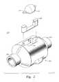
- FIG. 2is an exploded view of an exemplary expander tool.
- FIG. 3is a cross-sectional view illustrating the expandable liner partially expanded into contact with the wellbore by the expander tool.
- FIG. 4Ais a cross-sectional view of the expandable liner fully expanded into contact with the surrounding wellbore.
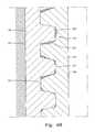
- FIG. 4Bis an enlarged cross-sectional view illustrating the swelling elastomer providing an effective seal at the threaded connection.
- FIG. 1is a cross-sectional view illustrating an expandable liner 150 of the present invention and a running assembly 170 being lowered into the wellbore 100 on a work string 140 .
- a casing string 105is disposed in the wellbore 100 , however, it should be noted that aspects of this present invention are not limited to use with a partially cased wellbore, but rather can be also be used with a cased or uncased wellbore.
- An uncased wellboreis known in the industry as an open hole wellbore that typically remains open to provide a flow path for hydrocarbons from the surrounding formation. Thereafter, the wellbore may be closed by employing the present invention in a similar manner as described below.
- the running assembly 170includes an upper torque anchor 160 to secure the running assembly 170 and the expandable liner 150 in the casing 105 .
- the upper torque anchor 160is in a retracted position to allow the running assembly 170 to place the expandable liner 150 in the desired location for expansion of the liner 150 .
- a lower torque anchor 125which is disposed below the upper torque anchor 160 , is used to attach the expandable liner 150 to the running assembly 170 .
- a motor 145is disposed at the lower end of the torque anchor 125 to provide rotational force to turn an expander tool 115 .
- FIG. 1Adepicts the expander tool 115 with rollers 116 retracted, so that the expander tool 115 may be easily moved and placed in the desired location for expansion of the liner 150 .
- hydraulic pressureis used to actuate the pistons (not shown) and to extend the rollers 116 so that they may contact the inner surface of the expandable liner 150 , thereby expanding the liner 150 into the wellbore 100 .
- hydraulic fluid(not shown) is pumped from the surface to the expander tool 115 through the work string 140 .
- the expandable liner 150includes an upper tubular 180 having an inner surface 183 and an outer surface 184 .
- the upper tubular 180also includes a connection means or a threaded portion 182 on the inner surface 183 which is typically known to one skilled in the art as a female thread.
- the expandable liner 150further includes a lower tubular 185 having an inner surface 188 and an outer surface 189 .
- the lower tubular 185includes a connection means or threaded portion 187 on the outer surface 189 , which is typically known to one skilled in the art as a male thread.
- the connecting means of the upper and lower tubularsmay be brought together to form a threaded connection 175 .
- FIG. 1Bis an enlarged cross-sectional view illustrating a swelling elastomer 205 disposed on the threaded connection 175 between the upper tubular 180 and the lower tubular 185 .
- a coating of the swelling elastomer 205may be applied to the threaded portion 182 of the upper tubular 180 prior to the connection to the lower tubular 185 . Thereafter, the threaded portion 182 on the upper tubular 180 mates with the threaded portion 187 on the lower tubular 185 to form the threaded connection 175 .
- the swelling elastomer 205creates a fluid tight seal between the tubulars 180 , 185 by filling the voids between the metal-to-metal seal created in the threaded connection 175 .
- the swelling elastomer 205may be applied to the threaded portion 187 on the lower tubular 185 prior to the connection to the upper tubular 180 .
- the swelling elastomer 205may be applied to both the threaded portion 182 on the upper tubular 180 and the threaded portion 187 on the lower tubular 185 .
- a very thin coat of swelling elastomer 205is applied to the threaded portions 182 , 187 .
- the thickness of the swelling elastomer 205 coatingmay vary depending on the size and the type of thread used to connect the tubulars 180 , 185 .
- FIG. 1Billustrates the threaded connection 175 with the swelling elastomer 205 .
- this inventionis not limited to threaded connections but rather could be used with other types of expandable connections.
- the swelling elastomer 205is a cross-linked polymer that will swell multiple times its initial size upon activation by an activating agent.
- the activating agentstimulates the polymer chains of the swelling elastomer 205 both radial and axially.
- an activating agentsuch as a wellbore fluid or some form of hydraulic fluid activates the swelling elastomer 205 .
- other embodimentsmay employ different types of swelling elastomers that are activated by other forms of activating agents.
- the elastomer 205is maintained within a predetermined location.
- the threaded portions 182 , 187substantially enclose the swelling elastomer 205 , thereby preventing any fluid or activating agent from contacting the swelling elastomer 205 .
- FIG. 2is an exploded view of an exemplary expander tool 115 for expanding the liner 150 .
- the expander tool 115has a body 102 that is hollow and generally tubular with connectors 104 and 106 for connection to other components (not shown) of a downhole assembly.
- the connectors 104 and 106are of a reduced diameter compared to the outside diameter of the longitudinally central body part of the tool 115 .
- the central body part 102 of the expander tool 115 shown in FIG. 2has three recesses 114 , each holding a respective roller 116 .
- Each of the recesses 114has parallel sides and extends radially from a radially perforated tubular core (not shown) of the tool 115 .
- Each of the mutually identical rollers 116is somewhat cylindrical and barreled.
- Each of the rollers 116is mounted by means of an axle 118 at each end of the respective roller 116 and the axles are mounted in slidable pistons 120 .
- the rollers 116are arranged for rotation about a respective rotational axis that is parallel to the longitudinal axis of the tool 115 and radially offset therefrom at 120-degree mutual circumferential separations around the central body 102 .
- the axles 118are formed as integral end members of the rollers 116 , with the pistons 120 being radially slidable, one piston 120 being slidably sealed within each radially extended recess 114 .
- the inner end of each piston 120is exposed to the pressure of fluid within the hollow core of the tool 115 by way of the radial perforations in the tubular core.
- pressurized fluidprovided from the surface of the well, via the work string (not shown), can actuate the pistons 120 and cause them to extend outward allowing the rollers 116 contact the inner surfaces 183 , 188 of the tubulars 180 , 185 .
- FIG. 3is a cross-sectional view illustrating the expandable liner 150 partially expanded into contact with the wellbore 100 by the expander tool 115 .
- the upper torque anchor(not shown) is energized to ensure the running assembly and the expandable liner 150 will not rotate during the expansion operation.
- Hydraulic pressureis increased to a predetermined pressure to actuate the pistons in the expander tool 115 .
- the rollers 116are extended until they contact the inner surface 183 of the expandable tubular 180 .
- the rollers 116 of the expander tool 115are further extended until the rollers 116 plastically deform the tubular 180 into a state of permanent expansion.
- the motor(not shown) rotates the expander tool 115 during the expansion process, and the tubular 180 is expanded until the outer surface 184 contacts the inner surface of the wellbore 100 .
- the expander tool 115expands the expandable liner 150
- the cross-sectional thickness of the expandable liner 150is necessarily reduced. Therefore, as the rollers 116 expand the threaded connection 175 , the initially tight fit between the threaded portions 182 , 187 become slackened, thereby affecting the seal at the threaded connection 175 .
- the slacked threaded connection 175allows wellbore fluid in an annulus 165 to contact the swelling elastomer 205 , thereby causing the polymer chains of the elastomer 205 to shift positions, and expand the swelling elastomer 205 both laterally and radially as shown in FIGS. 4A and 4B .
- FIG. 4Ais a cross-sectional view of the expandable liner 150 fully expanded into contact with the surrounding wellbore 100 .
- the upper tubular 180 , the threaded connection 175 and the lower tubular 185are fully expanded into the wellbore 100 .
- the swelling elastomer 205has sealed off any voids in the threaded connection 175 .
- the liner 150 of this present inventionmay be expanded into the wellbore 100 without any leakage of the wellbore fluid through the threaded connection 175 of the liner 150 .
- FIG. 4Bis an enlarged cross-sectional view illustrating the swelling elastomer 205 providing an effective seal at the threaded connection 175 .
- the threaded portions 182 , 187have shifted as the wall of the tubulars 180 , 185 became thin during the expansion operation.
- the slack between the threaded portions 182 , 187breaks the fluid tight seal, thereby allowing wellbore fluid in the annulus to leak through the threaded connection 175 to expose the swelling elastomer 205 to the wellbore fluid.
- the wellbore fluidactivates the swelling elastomer 205 , thereby causing the polymer chains to expand the swelling elastomer 205 both laterally and radially to fill the voids of the connection.
- the fluid tight seal between the threaded portion 182 of the upper tubular 180 and the threaded portion 187 of the lower tubular 185is preserved.
- wellbore fluidis prevented from leaking through the threaded connection 175 .
- the expandable liner assembly and a running assemblyare lowered to a desired location in the wellbore on a work string. Thereafter, the upper torque anchor is activated to secure the liner assembly and running assembly in the wellbore.
- hydraulic pressureis increased to a predetermined pressure to actuate the pistons in the expander tool.
- the rollersare extended until they contact the inner surface of the expandable liner.
- the rollers of the expander toolare further extended until the rollers plastically deform the liner into a state of permanent expansion.
- the motorrotates the expander tool during the expansion process, and the liner is expanded until the outer surface contacts the inner surface of the wellbore.
- the cross-sectional thickness of the expandable lineris necessarily reduced. Therefore, as the rollers expand the threaded connection, the initially tight fit between the threaded portions become slack, thereby affecting the seal at the threaded connection.
- the slackness at the threaded connectionallows wellbore fluid in the annulus to contact the swelling elastomer, thereby causing the polymer chains of the elastomer to shift positions, and expand the swelling elastomer both laterally and radially to fill the voids in the threaded connection.
Landscapes
- Engineering & Computer Science (AREA)
- Geology (AREA)
- Mining & Mineral Resources (AREA)
- Life Sciences & Earth Sciences (AREA)
- General Life Sciences & Earth Sciences (AREA)
- Fluid Mechanics (AREA)
- Environmental & Geological Engineering (AREA)
- Physics & Mathematics (AREA)
- Geochemistry & Mineralogy (AREA)
- Mechanical Engineering (AREA)
- General Engineering & Computer Science (AREA)
- Earth Drilling (AREA)
- Materials For Medical Uses (AREA)
- Lining Or Joining Of Plastics Or The Like (AREA)
- Pipe Accessories (AREA)
Abstract
Description
1. Field of the Invention
The present invention relates to wellbore completion. More particularly, the invention relates to an apparatus and method for attaching and sealing two tubulars. More particularly still, the invention relates to maintaining a seal at the connection point between the two tubulars during the expansion operation.
2. Description of the Related Art
In the drilling of oil and gas wells, a wellbore is formed using a drill bit that is urged downwardly at a lower end of a drill string. After drilling a predetermined depth, the drill string and bit are removed, and the wellbore is typically lined with a string of steel pipe called casing. The casing provides support to the wellbore and facilitates the isolation of certain areas of the wellbore adjacent hydrocarbon bearing formations. The casing typically extends down the wellbore from the surface of the well to a designated depth. An annular area is thus defined between the outside of the casing and the earth formation. This annular area is filled with cement to permanently set the casing in the wellbore and to facilitate the isolation of production zones and fluids at different depths within the wellbore.
It is common to employ more than one string of casing in a wellbore. In this respect, a first string of casing is set in the wellbore when the well is drilled to a first designated depth. The well is then drilled to a second designated depth, and a second string of casing, or liner, is run into the well to a depth whereby the upper portion of the second liner overlaps the lower portion of the first string of casing. The second liner string is then fixed or hung in the wellbore, usually by some mechanical slip mechanism well-known in the art, and cemented. This process is typically repeated with additional casing strings until the well has been drilled to total depth.
Operators are continually searching for means to improve functionality and reduce costs in their drilling operations. This has been achieved in the past in relatively small increments by such things as discrete technological improvements and novel contracting strategies. It is inevitable that these incremental gains are diminishing. The industry needs a radical “next step.” The monobore well is this step.
Monobore wells have a uniform through-bore from the surface casing to the production zones. Today, wells are constructed by progressively securing the borehole with several intermediate casings before the production casing is run. Monobore well technology will eliminate these intermediate casing strings through the use of expandable liners. Monobore wells consist of a sequence of expandable liners that are run through the existing casing, then expanded to achieve the same post-expansion through-bore. A monobore well features each progressive borehole section being cased without a reduction of casing size.
Many conventional wells drilled today consist of a 26-inch or 30-inch conductor and 20-inch or 18 5.8-inch surface casing (or similar sizes), and have several intermediate casings before a 9 5.8-inch production casing is run. The monobore well offers the advantage of being able to start with a much smaller surface casing but still resulting in a 9 5.8-inch production casing. Because top-hole sizes are reduced, less drilling fluid is required and fewer cuttings are created which means less cleaning of the cuttings, and the environmental problem of drilling waste disposal is reduced. Also, with a smaller surface casing size (and only one other actual casing string), the wellhead can be simplified, as can the BOP'S (blow out protectors) and risers. Many drilling plans include a contingency casing or liner to allow for problem zones. Careful planning of a monobore well enables problem zones to be secured without sacrificing a casing size in the well design. Additionally, running expandable liners instead of long casing strings will result in valuable time savings.
Generally, expandable liners for a monobore well or a conventional well are constructed of 38-foot long tubulars. Each expandable liner includes a female thread at the top and a male thread at the bottom. Typically, the top and bottom threaded portions are expandable in the same manner as the expandable liner. A series of expandable liners are commonly screwed together as they are lowered in the wellbore. As the female thread is connected with the male thread, a metal-to-metal seal is created. Additionally, two external O-rings may be disposed on the threads between the two expandable liners to enhance the sealing effect between the male and female thread.
After the entire length of expandable liner is deployed into the wellbore, the expandable liners are typically expanded by the use of a cone-shaped mandrel or by an expander tool. The expander tool is generally run into the wellbore on a tubular string and includes expandable, fluid actuated members disposed on a body. There are a number of advantages to expanding solids using a rotary tool as the expander tool, rather than existing methods involving driving a fixed cone through the pipe. For example, the process is controllable, thereby allowing expansion to be initiated when and wherever required. If necessary, the expander tool can be recovered in a mid-expansion position, and redeployed to continue the operation. Further, the rollers reduce the friction between the tool and the pipe, which allows the expandable liners to be expanded from the top down.
While expanding expandable liners in a wellbore offers obvious advantages, there are problems associated with using the technology. By plastically deforming the expandable liner, the cross-sectional thickness of the expandable liner is necessarily reduced. As a result, the tight metal-to-metal seal created between the female thread and the male thread becomes slack, thereby jeopardizing the seal at the threaded connection. Simply increasing the initial cross-sectional thickness of the expandable liner to compensate for the reduced wall thickness after expansion results in an increase in the amount of force needed to expand the expandable liner.
A need, therefore, exists for an expandable liner connection between two expandable tubulars that maintains its rigidity after the expansion process. There is a further need for an expandable liner connection providing an effective seal at the threaded connection between the expandable liner strings. There is yet a further need for an effective method for ensuring wellbore fluid will not leak through the expandable liners at the threaded connection.
The present invention generally relates to an apparatus for use in a wellbore. In one aspect, the apparatus includes a first tubular having a connection means at the end thereof and a second tubular having a mating connection means at an end thereof. The connection means and mating connection means are constructed and arranged to form a connection between the tubulars. The apparatus further includes a swelling elastomer disposable between the connection means and the mating connection means, the swelling elastomer expandable upon contact with an activating agent.
In another aspect, the invention provides a method for utilizing an expandable connection in a wellbore. The method includes running an assembly on a tubular string into the wellbore. The assembly includes a first tubular having a connection means, a second tubular having a mating connection means, the connection means and mating connection means are constructed and arranged to form a connection between the tubulars. The assembly also includes a swelling elastomer disposable between the connection means and the mating connection means. The method further includes the steps of applying a force to an inner surface of the connection and expanding the assembly radially outward. The method also includes the step of exposing the swelling elastomer to an activating agent, thereby ensuring that a space within the connection is substantially filled with the swelling elastomer.
So that the manner in which the above recited features of the present invention can be understood in detail, a more particular description of the invention, briefly summarized above, may be had by reference to embodiments, some of which are illustrated in the appended drawings. It is to be noted, however, that the appended drawings illustrate only typical embodiments of this invention and are therefore not to be considered limiting of its scope, for the invention may admit to other equally effective embodiments.
The runningassembly 170 includes an upper torque anchor160 to secure the runningassembly 170 and theexpandable liner 150 in thecasing 105. As shown inFIG. 1A , the upper torque anchor160 is in a retracted position to allow the runningassembly 170 to place theexpandable liner 150 in the desired location for expansion of theliner 150. Additionally, alower torque anchor 125, which is disposed below the upper torque anchor160, is used to attach theexpandable liner 150 to the runningassembly 170. Amotor 145 is disposed at the lower end of thetorque anchor 125 to provide rotational force to turn anexpander tool 115.
Theexpandable liner 150 includes anupper tubular 180 having aninner surface 183 and anouter surface 184. Theupper tubular 180 also includes a connection means or a threadedportion 182 on theinner surface 183 which is typically known to one skilled in the art as a female thread. As shown, theexpandable liner 150 further includes a lower tubular185 having aninner surface 188 and anouter surface 189. Additionally, the lower tubular185 includes a connection means or threadedportion 187 on theouter surface 189, which is typically known to one skilled in the art as a male thread. The connecting means of the upper and lower tubulars may be brought together to form a threadedconnection 175.
In one embodiment, the swellingelastomer 205 is a cross-linked polymer that will swell multiple times its initial size upon activation by an activating agent. Generally, the activating agent stimulates the polymer chains of the swellingelastomer 205 both radial and axially. In the preferred embodiment, an activating agent such as a wellbore fluid or some form of hydraulic fluid activates the swellingelastomer 205. However, other embodiments may employ different types of swelling elastomers that are activated by other forms of activating agents.
To keep the swellingelastomer 205 in an inactivated state during the run-in operation, theelastomer 205 is maintained within a predetermined location. In the preferred embodiment, the threadedportions elastomer 205, thereby preventing any fluid or activating agent from contacting the swellingelastomer 205.
Theexpandable liner 150 of the present invention is expanded by theexpander tool 115 acting outwardly against theinside surfaces lower tubulars FIG. 2 is an exploded view of anexemplary expander tool 115 for expanding theliner 150. Theexpander tool 115 has abody 102 that is hollow and generally tubular withconnectors connectors tool 115.
Thecentral body part 102 of theexpander tool 115 shown inFIG. 2 has threerecesses 114, each holding arespective roller 116. Each of therecesses 114 has parallel sides and extends radially from a radially perforated tubular core (not shown) of thetool 115. Each of the mutuallyidentical rollers 116 is somewhat cylindrical and barreled. Each of therollers 116 is mounted by means of anaxle 118 at each end of therespective roller 116 and the axles are mounted inslidable pistons 120. Therollers 116 are arranged for rotation about a respective rotational axis that is parallel to the longitudinal axis of thetool 115 and radially offset therefrom at 120-degree mutual circumferential separations around thecentral body 102. Theaxles 118 are formed as integral end members of therollers 116, with thepistons 120 being radially slidable, onepiston 120 being slidably sealed within each radially extendedrecess 114. The inner end of eachpiston 120 is exposed to the pressure of fluid within the hollow core of thetool 115 by way of the radial perforations in the tubular core. In this manner, pressurized fluid provided from the surface of the well, via the work string (not shown), can actuate thepistons 120 and cause them to extend outward allowing therollers 116 contact theinner surfaces tubulars
In operation, the expandable liner assembly and a running assembly are lowered to a desired location in the wellbore on a work string. Thereafter, the upper torque anchor is activated to secure the liner assembly and running assembly in the wellbore. After the expander tool is located at the desired depth, hydraulic pressure is increased to a predetermined pressure to actuate the pistons in the expander tool. Upon actuation of the pistons, the rollers are extended until they contact the inner surface of the expandable liner. The rollers of the expander tool are further extended until the rollers plastically deform the liner into a state of permanent expansion. The motor rotates the expander tool during the expansion process, and the liner is expanded until the outer surface contacts the inner surface of the wellbore. As the expander tool expands the liner, the cross-sectional thickness of the expandable liner is necessarily reduced. Therefore, as the rollers expand the threaded connection, the initially tight fit between the threaded portions become slack, thereby affecting the seal at the threaded connection. The slackness at the threaded connection allows wellbore fluid in the annulus to contact the swelling elastomer, thereby causing the polymer chains of the elastomer to shift positions, and expand the swelling elastomer both laterally and radially to fill the voids in the threaded connection.
While the foregoing is directed to embodiments of the present invention, other and further embodiments of the invention may be devised without departing from the basic scope thereof, and the scope thereof is determined by the claims that follow.
Claims (23)
1. An apparatus for use in a wellbore, the apparatus comprising:
a first expandable tubular having a connection means at an end thereof;
a second expandable tubular having a mating connection means at an end thereof, the connection means and mating connection means constructed and arranged to form a connection between the tubulars; and
a swelling elastomer disposable between the connection means and the mating connection means, the swelling elastomer expandable upon contact with an activating agent.
2. The apparatus ofclaim 1 , wherein the swelling elastomer fills a space within the connection.
3. The apparatus ofclaim 2 , wherein upon an application of a radially outward force supplied to an inner surface of the connection, the first and second expandable tubulars expand radially outward.
4. The apparatus ofclaim 3 , wherein the application of the radially outward force supplied to the inner surface causes the activating agent to contact the swelling elastomer, thereby causing the swelling elastomer to expand to fill the space.
5. The apparatus ofclaim 3 , wherein the radially outward force is applied by an expander tool having at least one fluid actuated expander member extendable radially outwards.
6. The apparatus ofclaim 3 , wherein the radially outward force is applied by a cone shaped member.
7. A method for utilizing an expandable connection in a wellbore, comprising:
running an assembly on a tubular string into the wellbore, the assembly including:
a first tubular having a connection means;
a second tubular having a mating connection means, the connection means and mating connection means constructed and arranged to form a connection between the tubulars; and
a swelling elastomer disposable between the connection means and the mating connection means;
applying a force to an inner surface of the connection;
expanding the assembly radially outward; and
exposing the swelling elastomer to an activating agent, thereby ensuring that a space within the connection is substantially filled with the swelling elastomer.
8. The method ofclaim 7 , wherein the swelling elastomer is exposed to the activating agent as the assembly is expanded.
9. The method ofclaim 7 , wherein the connection means consists of threads disposed on an outer surface of the first tubular and the mating connection means consists of threads disposed on an inner surface of the second tubular.
10. The method ofclaim 9 , wherein the swelling elastomer is disposed on the threads of the first tubular.
11. The method ofclaim 9 , wherein the swelling elastomer is disposed on the threads of the second tubular.
12. The method ofclaim 9 , wherein the swelling elastomer is disposed on the threads of both the first and second tubular.
13. The method ofclaim 9 , wherein the application of the force to the inner surface of the assembly causes the activating agent to react with the swelling elastomer.
14. The method ofclaim 13 , further including the step of allowing the activated swelling elastomer to fill in a gap between the threads on the first tubular and the threads on the second tubular.
15. The method ofclaim 7 , wherein the activating agent is wellbore fluid.
16. The method ofclaim 7 , wherein the force is applied by an expander tool having at least one fluid actuated expander member extendable radially outwards.
17. The method ofclaim 7 , wherein the force is applied by a cone shaped member.
18. An expandable connection comprising:
a first member having a connection means at the end thereof;
a second member having a mating connection means at an end thereof, the connection means and mating connection means formable into a connection; and
a swelling elastomer disposed between the connection means and the mating connection means, whereby a force supplied to an inner surface causes the first and second members to expand radially outward and to permit an activating agent to activate the swelling elastomer to fill an annular area between the connection means and the mating connection means.
19. An apparatus for use in a wellbore, the apparatus comprising:
a first tubular having a connection means at an end thereof;
a second tubular having a mating connection means at an end thereof, the connection means and mating connection means constructed and arranged to form a connection between the tubulars; and
a swelling elastomer disposable between the connection means and the mating connection means, the swelling elastomer expandable upon contact with wellbore fluid.
20. An apparatus for use in a wellbore, the apparatus comprising:
a first tubular having a threaded portion on an outer surface at an end thereof;
a second tubular having a mating threaded portion on an inner surface at an end thereof, the threaded portion and the mating threaded portion constructed and arranged to form a connection between the tubulars; and
a swelling elastomer disposable between the threaded portion and the mating threaded portion, the swelling elastomer expandable upon contact with an activating agent.
21. The apparatus ofclaim 20 , wherein the swelling elastomer is disposed on the threaded portion of the first tubular.
22. The apparatus ofclaim 20 , wherein the swelling elastomer is disposed on the threaded portion of the second tubular.
23. The apparatus ofclaim 20 , wherein the swelling elastomer is disposed on the threaded portion of both the first and second tubular.
Priority Applications (3)
| Application Number | Priority Date | Filing Date | Title |
|---|---|---|---|
| US10/255,571US6840325B2 (en) | 2002-09-26 | 2002-09-26 | Expandable connection for use with a swelling elastomer |
| GB0322615AGB2393467B (en) | 2002-09-26 | 2003-09-26 | Expandable connection for use with a swelling elastomer |
| CA002442891ACA2442891C (en) | 2002-09-26 | 2003-09-26 | Expandable connection for use with a swelling elastomer |
Applications Claiming Priority (1)
| Application Number | Priority Date | Filing Date | Title |
|---|---|---|---|
| US10/255,571US6840325B2 (en) | 2002-09-26 | 2002-09-26 | Expandable connection for use with a swelling elastomer |
Publications (2)
| Publication Number | Publication Date |
|---|---|
| US20040060706A1 US20040060706A1 (en) | 2004-04-01 |
| US6840325B2true US6840325B2 (en) | 2005-01-11 |
Family
ID=29401050
Family Applications (1)
| Application Number | Title | Priority Date | Filing Date |
|---|---|---|---|
| US10/255,571Expired - Fee RelatedUS6840325B2 (en) | 2002-09-26 | 2002-09-26 | Expandable connection for use with a swelling elastomer |
Country Status (3)
| Country | Link |
|---|---|
| US (1) | US6840325B2 (en) |
| CA (1) | CA2442891C (en) |
| GB (1) | GB2393467B (en) |
Cited By (52)
| Publication number | Priority date | Publication date | Assignee | Title |
|---|---|---|---|---|
| US20030146003A1 (en)* | 2001-12-27 | 2003-08-07 | Duggan Andrew Michael | Bore isolation |
| US20040194971A1 (en)* | 2001-01-26 | 2004-10-07 | Neil Thomson | Device and method to seal boreholes |
| US20050000697A1 (en)* | 2002-07-06 | 2005-01-06 | Abercrombie Simpson Neil Andrew | Formed tubulars |
| US20050199401A1 (en)* | 2004-03-12 | 2005-09-15 | Schlumberger Technology Corporation | System and Method to Seal Using a Swellable Material |
| US20050269108A1 (en)* | 2002-12-23 | 2005-12-08 | Weatherford/Lamb, Inc. | Expandable sealing apparatus |
| US20060175065A1 (en)* | 2004-12-21 | 2006-08-10 | Schlumberger Technology Corporation | Water shut off method and apparatus |
| US20070044962A1 (en)* | 2005-08-26 | 2007-03-01 | Schlumberger Technology Corporation | System and Method for Isolating Flow In A Shunt Tube |
| US20070284109A1 (en)* | 2006-06-09 | 2007-12-13 | East Loyd E | Methods and devices for treating multiple-interval well bores |
| US20080017376A1 (en)* | 2006-06-29 | 2008-01-24 | Badalamenti Anthony M | Swellable Elastomers and Associated Methods |
| US20080156499A1 (en)* | 2007-01-03 | 2008-07-03 | Richard Lee Giroux | System and methods for tubular expansion |
| US20080164026A1 (en)* | 2007-01-04 | 2008-07-10 | Johnson Michael H | Method of isolating and completing multi-zone frac packs |
| US20080220991A1 (en)* | 2007-03-06 | 2008-09-11 | Halliburton Energy Services, Inc. - Dallas | Contacting surfaces using swellable elements |
| US7510011B2 (en) | 2006-07-06 | 2009-03-31 | Schlumberger Technology Corporation | Well servicing methods and systems employing a triggerable filter medium sealing composition |
| US20090176667A1 (en)* | 2008-01-03 | 2009-07-09 | Halliburton Energy Services, Inc. | Expandable particulates and methods of their use in subterranean formations |
| US20090200043A1 (en)* | 2008-02-13 | 2009-08-13 | Olinger Robert L | Vented packer element for downwell packing system |
| US7575062B2 (en) | 2006-06-09 | 2009-08-18 | Halliburton Energy Services, Inc. | Methods and devices for treating multiple-interval well bores |
| US20090205817A1 (en)* | 2008-02-15 | 2009-08-20 | Gustafson Eric J | Downwell system with differentially swellable packer |
| US20090205842A1 (en)* | 2008-02-15 | 2009-08-20 | Peter Williamson | On-site assemblable packer element for downwell packing system |
| US20090205841A1 (en)* | 2008-02-15 | 2009-08-20 | Jurgen Kluge | Downwell system with activatable swellable packer |
| US20090205818A1 (en)* | 2008-02-15 | 2009-08-20 | Jurgen Klunge | Downwell system with swellable packer including blowing agent |
| US20090205816A1 (en)* | 2008-02-15 | 2009-08-20 | De Dilip K | Downwell system with swellable packer element and composition for same |
| US20100096143A1 (en)* | 2008-10-20 | 2010-04-22 | Tesco Corporation (Us) | Method for Installing Wellbore String Devices |
| US20100314111A1 (en)* | 2009-06-15 | 2010-12-16 | Karcher Jeffery D | Cement Compositions Comprising Particulate Foamed Elastomers and Associated Methods |
| US20110139453A1 (en)* | 2009-12-10 | 2011-06-16 | Halliburton Energy Services, Inc. | Fluid flow control device |
| US20120049462A1 (en)* | 2009-02-14 | 2012-03-01 | Malcolm Pitman | Connector seal |
| US8616290B2 (en) | 2010-04-29 | 2013-12-31 | Halliburton Energy Services, Inc. | Method and apparatus for controlling fluid flow using movable flow diverter assembly |
| US8657017B2 (en) | 2009-08-18 | 2014-02-25 | Halliburton Energy Services, Inc. | Method and apparatus for autonomous downhole fluid selection with pathway dependent resistance system |
| US8991506B2 (en) | 2011-10-31 | 2015-03-31 | Halliburton Energy Services, Inc. | Autonomous fluid control device having a movable valve plate for downhole fluid selection |
| US9127526B2 (en) | 2012-12-03 | 2015-09-08 | Halliburton Energy Services, Inc. | Fast pressure protection system and method |
| US9260952B2 (en) | 2009-08-18 | 2016-02-16 | Halliburton Energy Services, Inc. | Method and apparatus for controlling fluid flow in an autonomous valve using a sticky switch |
| US9291032B2 (en) | 2011-10-31 | 2016-03-22 | Halliburton Energy Services, Inc. | Autonomous fluid control device having a reciprocating valve for downhole fluid selection |
| US9303483B2 (en) | 2007-02-06 | 2016-04-05 | Halliburton Energy Services, Inc. | Swellable packer with enhanced sealing capability |
| US9404349B2 (en) | 2012-10-22 | 2016-08-02 | Halliburton Energy Services, Inc. | Autonomous fluid control system having a fluid diode |
| US9695654B2 (en) | 2012-12-03 | 2017-07-04 | Halliburton Energy Services, Inc. | Wellhead flowback control system and method |
| US20180187529A1 (en)* | 2015-07-01 | 2018-07-05 | Shell Oil Company | Expanding well tubulars interconnected by pin-box assemblies optimized for expansion |
| US11448042B1 (en) | 2021-09-21 | 2022-09-20 | Halliburton Energy Services, Inc. | Expandable metal for junction locking and junction sealant applications |
| US11717875B2 (en) | 2021-10-28 | 2023-08-08 | Saudi Arabian Oil Company | Electrically initiated elastomer member expansion for controlling tubing member assembly diameter |
| US12188328B2 (en) | 2023-05-15 | 2025-01-07 | Saudi Arabian Oil Company | Wellbore back pressure valve with pressure gauge |
| US12234701B2 (en) | 2022-09-12 | 2025-02-25 | Saudi Arabian Oil Company | Tubing hangers and related methods of isolating a tubing |
| US12258828B2 (en) | 2022-06-15 | 2025-03-25 | Halliburton Energy Services, Inc. | Sealing/anchoring tool employing a hydraulically deformable member and an expandable metal circlet |
| US12258723B2 (en) | 2021-06-01 | 2025-03-25 | Halliburton Energy Services, Inc. | Expanding metal used in forming support structures |
| US12326060B2 (en) | 2021-05-21 | 2025-06-10 | Halliburton Energy Services, Inc. | Wellbore anchor including one or more activation chambers |
| US12338705B2 (en) | 2020-08-13 | 2025-06-24 | Halliburton Energy Services, Inc. | Expandable metal displacement plug |
| US12345117B2 (en) | 2021-05-28 | 2025-07-01 | Halliburton Energy Services, Inc. | Individual separate chunks of expandable metal |
| US12345116B2 (en) | 2021-04-12 | 2025-07-01 | Halliburton Energy Services, Inc. | Expandable metal as backup for elastomeric elements |
| US12345115B2 (en) | 2020-01-17 | 2025-07-01 | Halliburton Energy Services, Inc. | Heaters to accelerate setting of expandable metal |
| US12345119B2 (en) | 2021-05-28 | 2025-07-01 | Halliburton Energy Services, Inc. | Rapid setting expandable metal |
| US12352127B2 (en) | 2020-01-17 | 2025-07-08 | Halliburton Energy Services, Inc. | Voltage to accelerate/decelerate expandable metal |
| US12378832B2 (en) | 2021-10-05 | 2025-08-05 | Halliburton Energy Services, Inc. | Expandable metal sealing/anchoring tool |
| US12385340B2 (en) | 2022-12-05 | 2025-08-12 | Halliburton Energy Services, Inc. | Reduced backlash sealing/anchoring assembly |
| US12421824B2 (en) | 2021-05-29 | 2025-09-23 | Halliburton Energy Services, Inc. | Using expandable metal as an alternate to existing metal to metal seals |
| US12442257B2 (en) | 2023-05-23 | 2025-10-14 | Saudi Arabian Oil Company | Completing and working over a wellbore |
Families Citing this family (84)
| Publication number | Priority date | Publication date | Assignee | Title |
|---|---|---|---|---|
| US7357188B1 (en) | 1998-12-07 | 2008-04-15 | Shell Oil Company | Mono-diameter wellbore casing |
| US7121352B2 (en) | 1998-11-16 | 2006-10-17 | Enventure Global Technology | Isolation of subterranean zones |
| US6557640B1 (en) | 1998-12-07 | 2003-05-06 | Shell Oil Company | Lubrication and self-cleaning system for expansion mandrel |
| US7231985B2 (en) | 1998-11-16 | 2007-06-19 | Shell Oil Company | Radial expansion of tubular members |
| US6823937B1 (en) | 1998-12-07 | 2004-11-30 | Shell Oil Company | Wellhead |
| US7603758B2 (en) | 1998-12-07 | 2009-10-20 | Shell Oil Company | Method of coupling a tubular member |
| AU2001269810B2 (en) | 1998-11-16 | 2005-04-07 | Shell Oil Company | Radial expansion of tubular members |
| US7195064B2 (en) | 1998-12-07 | 2007-03-27 | Enventure Global Technology | Mono-diameter wellbore casing |
| US7552776B2 (en) | 1998-12-07 | 2009-06-30 | Enventure Global Technology, Llc | Anchor hangers |
| US7363984B2 (en) | 1998-12-07 | 2008-04-29 | Enventure Global Technology, Llc | System for radially expanding a tubular member |
| GB2344606B (en) | 1998-12-07 | 2003-08-13 | Shell Int Research | Forming a wellbore casing by expansion of a tubular member |
| US7185710B2 (en) | 1998-12-07 | 2007-03-06 | Enventure Global Technology | Mono-diameter wellbore casing |
| AU770359B2 (en) | 1999-02-26 | 2004-02-19 | Shell Internationale Research Maatschappij B.V. | Liner hanger |
| JP3461750B2 (en)* | 1999-03-04 | 2003-10-27 | パナソニック コミュニケーションズ株式会社 | Communication apparatus, communication method, and caller information registration method |
| US7055608B2 (en) | 1999-03-11 | 2006-06-06 | Shell Oil Company | Forming a wellbore casing while simultaneously drilling a wellbore |
| US7350563B2 (en) | 1999-07-09 | 2008-04-01 | Enventure Global Technology, L.L.C. | System for lining a wellbore casing |
| US20050123639A1 (en)* | 1999-10-12 | 2005-06-09 | Enventure Global Technology L.L.C. | Lubricant coating for expandable tubular members |
| AU783245B2 (en) | 1999-11-01 | 2005-10-06 | Shell Internationale Research Maatschappij B.V. | Wellbore casing repair |
| US7234531B2 (en) | 1999-12-03 | 2007-06-26 | Enventure Global Technology, Llc | Mono-diameter wellbore casing |
| CA2416573A1 (en) | 2000-09-18 | 2002-03-21 | Shell Canada Ltd | Liner hanger with sliding sleeve valve |
| US7100685B2 (en) | 2000-10-02 | 2006-09-05 | Enventure Global Technology | Mono-diameter wellbore casing |
| CA2428819A1 (en) | 2001-01-03 | 2002-07-11 | Enventure Global Technology | Mono-diameter wellbore casing |
| US7410000B2 (en) | 2001-01-17 | 2008-08-12 | Enventure Global Technology, Llc. | Mono-diameter wellbore casing |
| JP4399121B2 (en)* | 2001-02-13 | 2010-01-13 | 富士フイルム株式会社 | Imaging system |
| WO2003004820A2 (en) | 2001-07-06 | 2003-01-16 | Enventure Global Technology | Liner hanger |
| GB2394979B (en) | 2001-07-06 | 2005-11-02 | Eventure Global Technology | Liner hanger |
| US7258168B2 (en)* | 2001-07-27 | 2007-08-21 | Enventure Global Technology L.L.C. | Liner hanger with slip joint sealing members and method of use |
| GB2396639B (en)* | 2001-08-20 | 2006-03-08 | Enventure Global Technology | An apparatus for forming a wellbore casing by use of an adjustable tubular expansion cone |
| US7513313B2 (en) | 2002-09-20 | 2009-04-07 | Enventure Global Technology, Llc | Bottom plug for forming a mono diameter wellbore casing |
| WO2004094766A2 (en) | 2003-04-17 | 2004-11-04 | Enventure Global Technology | Apparatus for radially expanding and plastically deforming a tubular member |
| CA2459910C (en)* | 2001-09-07 | 2010-04-13 | Enventure Global Technology | Adjustable expansion cone assembly |
| US20050103502A1 (en)* | 2002-03-13 | 2005-05-19 | Watson Brock W. | Collapsible expansion cone |
| WO2004081346A2 (en) | 2003-03-11 | 2004-09-23 | Enventure Global Technology | Apparatus for radially expanding and plastically deforming a tubular member |
| AU2002343651A1 (en) | 2001-11-12 | 2003-05-26 | Enventure Global Technology | Collapsible expansion cone |
| US7290605B2 (en) | 2001-12-27 | 2007-11-06 | Enventure Global Technology | Seal receptacle using expandable liner hanger |
| WO2003086675A2 (en) | 2002-04-12 | 2003-10-23 | Enventure Global Technology | Protective sleeve for threaded connections for expandable liner hanger |
| WO2004018824A2 (en) | 2002-08-23 | 2004-03-04 | Enventure Global Technology | Magnetic impulse applied sleeve method of forming a wellbore casing |
| WO2004018823A2 (en) | 2002-08-23 | 2004-03-04 | Enventure Global Technology | Interposed joint sealing layer method of forming a wellbore casing |
| WO2003089161A2 (en) | 2002-04-15 | 2003-10-30 | Enventure Global Technlogy | Protective sleeve for threaded connections for expandable liner hanger |
| WO2004027786A2 (en) | 2002-09-20 | 2004-04-01 | Enventure Global Technology | Protective sleeve for expandable tubulars |
| MXPA04007922A (en) | 2002-02-15 | 2005-05-17 | Enventure Global Technology | Mono-diameter wellbore casing. |
| US7360591B2 (en) | 2002-05-29 | 2008-04-22 | Enventure Global Technology, Llc | System for radially expanding a tubular member |
| GB2418943B (en) | 2002-06-10 | 2006-09-06 | Enventure Global Technology | Mono Diameter Wellbore Casing |
| GB0215668D0 (en)* | 2002-07-06 | 2002-08-14 | Weatherford Lamb | Coupling tubulars |
| AU2003265452A1 (en) | 2002-09-20 | 2004-04-08 | Enventure Global Technology | Pipe formability evaluation for expandable tubulars |
| GB2410280B (en) | 2002-09-20 | 2007-04-04 | Enventure Global Technology | Self-lubricating expansion mandrel for expandable tubular |
| US6997264B2 (en)* | 2002-10-10 | 2006-02-14 | Weatherford/Lamb, Inc. | Method of jointing and running expandable tubulars |
| US7886831B2 (en) | 2003-01-22 | 2011-02-15 | Enventure Global Technology, L.L.C. | Apparatus for radially expanding and plastically deforming a tubular member |
| WO2004067961A2 (en) | 2003-01-27 | 2004-08-12 | Enventure Global Technology | Lubrication system for radially expanding tubular members |
| GB0303152D0 (en)* | 2003-02-12 | 2003-03-19 | Weatherford Lamb | Seal |
| NO319620B1 (en)* | 2003-02-17 | 2005-09-05 | Rune Freyer | Device and method for selectively being able to shut off a portion of a well |
| GB2429996B (en) | 2003-02-26 | 2007-08-29 | Enventure Global Technology | Apparatus for radially expanding and plastically deforming a tubular member |
| US20050166387A1 (en)* | 2003-06-13 | 2005-08-04 | Cook Robert L. | Method and apparatus for forming a mono-diameter wellbore casing |
| GB0317395D0 (en)* | 2003-07-25 | 2003-08-27 | Weatherford Lamb | Sealing expandable tubing |
| GB0318181D0 (en)* | 2003-08-02 | 2003-09-03 | Weatherford Lamb | Seal arrangement |
| GB2421529B (en)* | 2003-09-02 | 2007-09-05 | Enventure Global Technology | A method of radially expanding and plastically deforming tubular members |
| US7712522B2 (en) | 2003-09-05 | 2010-05-11 | Enventure Global Technology, Llc | Expansion cone and system |
| CA2552722C (en)* | 2004-01-12 | 2012-08-07 | Shell Oil Company | Expandable connection |
| NO325434B1 (en)* | 2004-05-25 | 2008-05-05 | Easy Well Solutions As | Method and apparatus for expanding a body under overpressure |
| GB2432866A (en) | 2004-08-13 | 2007-06-06 | Enventure Global Technology | Expandable tubular |
| US7708068B2 (en) | 2006-04-20 | 2010-05-04 | Halliburton Energy Services, Inc. | Gravel packing screen with inflow control device and bypass |
| US8453746B2 (en)* | 2006-04-20 | 2013-06-04 | Halliburton Energy Services, Inc. | Well tools with actuators utilizing swellable materials |
| US7802621B2 (en) | 2006-04-24 | 2010-09-28 | Halliburton Energy Services, Inc. | Inflow control devices for sand control screens |
| US7469743B2 (en) | 2006-04-24 | 2008-12-30 | Halliburton Energy Services, Inc. | Inflow control devices for sand control screens |
| US20080041582A1 (en)* | 2006-08-21 | 2008-02-21 | Geirmund Saetre | Apparatus for controlling the inflow of production fluids from a subterranean well |
| US20080041588A1 (en)* | 2006-08-21 | 2008-02-21 | Richards William M | Inflow Control Device with Fluid Loss and Gas Production Controls |
| US20080041580A1 (en)* | 2006-08-21 | 2008-02-21 | Rune Freyer | Autonomous inflow restrictors for use in a subterranean well |
| GB2448924B (en)* | 2007-05-04 | 2010-09-15 | Dynamic Dinosaurs Bv | Methods for expanding tubular elements |
| US20080283238A1 (en)* | 2007-05-16 | 2008-11-20 | William Mark Richards | Apparatus for autonomously controlling the inflow of production fluids from a subterranean well |
| US9004155B2 (en)* | 2007-09-06 | 2015-04-14 | Halliburton Energy Services, Inc. | Passive completion optimization with fluid loss control |
| US7779910B2 (en)* | 2008-02-07 | 2010-08-24 | Halliburton Energy Services, Inc. | Expansion cone for expandable liner hanger |
| US7866406B2 (en) | 2008-09-22 | 2011-01-11 | Baker Hughes Incorporated | System and method for plugging a downhole wellbore |
| US8261842B2 (en) | 2009-12-08 | 2012-09-11 | Halliburton Energy Services, Inc. | Expandable wellbore liner system |
| CA2827462C (en)* | 2011-02-16 | 2016-01-19 | Weatherford/Lamb, Inc. | Anchoring seal |
| US11215021B2 (en) | 2011-02-16 | 2022-01-04 | Weatherford Technology Holdings, Llc | Anchoring and sealing tool |
| US9528352B2 (en)* | 2011-02-16 | 2016-12-27 | Weatherford Technology Holdings, Llc | Extrusion-resistant seals for expandable tubular assembly |
| CA2827460C (en) | 2011-02-16 | 2017-04-04 | Weatherford/Lamb, Inc. | Downhole tool having expandable annular member |
| US20120205092A1 (en)* | 2011-02-16 | 2012-08-16 | George Givens | Anchoring and sealing tool |
| US9260926B2 (en) | 2012-05-03 | 2016-02-16 | Weatherford Technology Holdings, Llc | Seal stem |
| CN104781501B (en) | 2012-08-28 | 2017-07-28 | 哈里伯顿能源服务公司 | Expandable tieback seal assembly |
| US9976349B2 (en)* | 2013-09-09 | 2018-05-22 | Weatherford Technology Holdings, Llc | Apparatus for preventing separation of downhole motor from drillstring |
| US9810037B2 (en) | 2014-10-29 | 2017-11-07 | Weatherford Technology Holdings, Llc | Shear thickening fluid controlled tool |
| US10180038B2 (en) | 2015-05-06 | 2019-01-15 | Weatherford Technology Holdings, Llc | Force transferring member for use in a tool |
| US20180154498A1 (en)* | 2016-12-05 | 2018-06-07 | Onesubsea Ip Uk Limited | Burnishing assembly systems and methods |
Citations (63)
| Publication number | Priority date | Publication date | Assignee | Title |
|---|---|---|---|---|
| US2094691A (en)* | 1933-05-31 | 1937-10-05 | United Gas Improvement Co | Packed joint and method of leakproofing the same |
| US2306160A (en) | 1938-07-29 | 1942-12-22 | Freyssinet Eugene | Packing device |
| US2519116A (en) | 1948-12-28 | 1950-08-15 | Shell Dev | Deformable packer |
| US2656891A (en) | 1948-03-02 | 1953-10-27 | Lester W Toelke | Apparatus for plugging wells |
| US2814517A (en) | 1956-09-18 | 1957-11-26 | Razdow Adolph | Coated metal tubular seal |
| US2945541A (en) | 1955-10-17 | 1960-07-19 | Union Oil Co | Well packer |
| US3147016A (en) | 1959-04-06 | 1964-09-01 | Traufler Daniel | Annular gaskets |
| US3385367A (en) | 1966-12-07 | 1968-05-28 | Kollsman Paul | Sealing device for perforated well casing |
| US3593799A (en) | 1969-07-29 | 1971-07-20 | Dow Chemical Co | Method of sealing a space with a hydrophilic solid gel |
| US3677987A (en) | 1970-01-26 | 1972-07-18 | Dow Chemical Co | Organo polymer cements with extended working time |
| US3690375A (en) | 1971-04-05 | 1972-09-12 | Harold E Shillander | Inflatable packer |
| US3740360A (en) | 1970-11-12 | 1973-06-19 | Dow Chemical Co | Sealing composition and method |
| US3918523A (en) | 1974-07-11 | 1975-11-11 | Ivan L Stuber | Method and means for implanting casing |
| US4078606A (en) | 1976-12-15 | 1978-03-14 | Brown Oil Tools, Inc. | Pressure actuated holding apparatus |
| US4137970A (en) | 1977-04-20 | 1979-02-06 | The Dow Chemical Company | Packer with chemically activated sealing member and method of use thereof |
| US4253676A (en) | 1979-06-15 | 1981-03-03 | Halliburton Company | Inflatable packer element with integral support means |
| US4300775A (en) | 1979-08-13 | 1981-11-17 | Caterpillar Tractor Co. | Liquid-filled radial seal |
| US4403660A (en) | 1980-08-08 | 1983-09-13 | Mgc Oil Tools, Inc. | Well packer and method of use thereof |
| US4406469A (en) | 1981-09-21 | 1983-09-27 | Baker International Corporation | Plastically deformable conduit seal for subterranean wells |
| US4449713A (en)* | 1980-10-17 | 1984-05-22 | Hayakawa Rubber Company Limited | Aqueously-swelling water stopper and a process of stopping water thereby |
| US4452463A (en) | 1981-09-25 | 1984-06-05 | Dresser Industries, Inc. | Packer sealing assembly |
| US4457369A (en) | 1980-12-17 | 1984-07-03 | Otis Engineering Corporation | Packer for high temperature high pressure wells |
| US4601498A (en) | 1982-11-15 | 1986-07-22 | Baker Oil Tools, Inc. | Deformable metal-to-metal seal |
| US4633950A (en) | 1985-05-28 | 1987-01-06 | Texaco Inc. | Method for controlling lost circulation of drilling fluids with hydrocarbon absorbent polymers |
| US4662450A (en) | 1985-09-13 | 1987-05-05 | Haugen David M | Explosively set downhole apparatus |
| US4674570A (en) | 1984-09-10 | 1987-06-23 | J.J. Seismic Flowing Hole Control (C.I.) Inc. | Bore hole plug |
| EP0237662A1 (en) | 1986-03-18 | 1987-09-23 | Halliburton Company | Downhole tool |
| US4730670A (en) | 1985-12-06 | 1988-03-15 | Baker Oil Tools, Inc. | High temperature packer for well conduits |
| US4762179A (en) | 1986-08-04 | 1988-08-09 | Halliburton Company | Pressure assist detonating bar and method for a tubing conveyed perforator |
| US4836940A (en) | 1987-09-14 | 1989-06-06 | American Colloid Company | Composition and method of controlling lost circulation from wellbores |
| US4862967A (en) | 1986-05-12 | 1989-09-05 | Baker Oil Tools, Inc. | Method of employing a coated elastomeric packing element |
| US4886117A (en) | 1986-10-24 | 1989-12-12 | Schlumberger Technology Corporation | Inflatable well packers |
| US4907651A (en) | 1987-12-21 | 1990-03-13 | Texaco Inc. | Metal-to-metal packer seal for downhole disconnectable pipe joint |
| US4913232A (en) | 1988-01-20 | 1990-04-03 | Hutchinson and Merip Oil Tools International | Method of isolating production zones in a well, and apparatus for implementing the method |
| US4919989A (en)* | 1989-04-10 | 1990-04-24 | American Colloid Company | Article for sealing well castings in the earth |
| US5086841A (en) | 1989-06-19 | 1992-02-11 | Nalco Chemical Company | Method of reducing circulation fluid loss using water absorbing polymer |
| US5165703A (en) | 1991-03-20 | 1992-11-24 | Oem Components, Inc. | Anti-extrusion centering seals and packings |
| US5195583A (en)* | 1990-09-27 | 1993-03-23 | Solinst Canada Ltd | Borehole packer |
| US5226492A (en) | 1992-04-03 | 1993-07-13 | Intevep, S.A. | Double seals packers for subterranean wells |
| US5271469A (en) | 1992-04-08 | 1993-12-21 | Ctc International | Borehole stressed packer inflation system |
| US5309993A (en) | 1990-08-27 | 1994-05-10 | Baker Hughes Incorporated | Chevron seal for a well tool |
| US5311938A (en) | 1992-05-15 | 1994-05-17 | Halliburton Company | Retrievable packer for high temperature, high pressure service |
| US5511620A (en) | 1992-01-29 | 1996-04-30 | Baugh; John L. | Straight Bore metal-to-metal wellbore seal apparatus and method of sealing in a wellbore |
| US5605195A (en) | 1994-12-22 | 1997-02-25 | Dowell, A Division Of Schlumber Technology Corporation | Inflation shape control system for inflatable packers |
| US5623993A (en) | 1992-08-07 | 1997-04-29 | Baker Hughes Incorporated | Method and apparatus for sealing and transfering force in a wellbore |
| US5676384A (en) | 1996-03-07 | 1997-10-14 | Cdi Seals, Inc. | Anti-extrusion apparatus made from PTFE impregnated steel mesh |
| US5738146A (en)* | 1996-02-16 | 1998-04-14 | Sekishin Sangyo Co., Ltd. | Method for rehabilitation of underground piping |
| US5749585A (en) | 1995-12-18 | 1998-05-12 | Baker Hughes Incorporated | Downhole tool sealing system with cylindrical biasing member with narrow width and wider width openings |
| US5787987A (en) | 1995-09-06 | 1998-08-04 | Baker Hughes Incorporated | Lateral seal and control system |
| US5803178A (en) | 1996-09-13 | 1998-09-08 | Union Oil Company Of California | Downwell isolator |
| US5833001A (en) | 1996-12-13 | 1998-11-10 | Schlumberger Technology Corporation | Sealing well casings |
| US5875847A (en) | 1996-07-22 | 1999-03-02 | Baker Hughes Incorporated | Multilateral sealing |
| US5941313A (en) | 1997-02-03 | 1999-08-24 | Pes, Inc | Control set downhole packer |
| US6009951A (en) | 1997-12-12 | 2000-01-04 | Baker Hughes Incorporated | Method and apparatus for hybrid element casing packer for cased-hole applications |
| US6041858A (en) | 1997-09-27 | 2000-03-28 | Pes, Inc. | High expansion downhole packer |
| US6073692A (en) | 1998-03-27 | 2000-06-13 | Baker Hughes Incorporated | Expanding mandrel inflatable packer |
| WO2002020941A1 (en) | 2000-09-08 | 2002-03-14 | Freyer, Rune | Well packing |
| WO2002059452A1 (en) | 2001-01-26 | 2002-08-01 | E2 Tech Limited | Device and method to seal boreholes |
| US6446717B1 (en) | 2000-06-01 | 2002-09-10 | Weatherford/Lamb, Inc. | Core-containing sealing assembly |
| FR2834326A1 (en) | 2002-01-03 | 2003-07-04 | Vallourec Mannesmann Oil & Gas | High performance tubular joint, has threaded section of shape ensuring seal after joint has been expanded |
| FR2834325A1 (en) | 2002-01-03 | 2003-07-04 | Vallourec Mannesmann Oil & Gas | TUBULAR THREADED JOINT WITH SEALING SURFACES |
| GB2386626A (en) | 2002-03-21 | 2003-09-24 | Halliburton Energy Serv Inc | Downhole tubular string connections |
| GB2387405A (en) | 2001-01-03 | 2003-10-15 | Enventure Global Technology | Mono-diameter wellbore casing |
- 2002
- 2002-09-26USUS10/255,571patent/US6840325B2/ennot_activeExpired - Fee Related
- 2003
- 2003-09-26CACA002442891Apatent/CA2442891C/ennot_activeExpired - Fee Related
- 2003-09-26GBGB0322615Apatent/GB2393467B/ennot_activeExpired - Fee Related
Patent Citations (63)
| Publication number | Priority date | Publication date | Assignee | Title |
|---|---|---|---|---|
| US2094691A (en)* | 1933-05-31 | 1937-10-05 | United Gas Improvement Co | Packed joint and method of leakproofing the same |
| US2306160A (en) | 1938-07-29 | 1942-12-22 | Freyssinet Eugene | Packing device |
| US2656891A (en) | 1948-03-02 | 1953-10-27 | Lester W Toelke | Apparatus for plugging wells |
| US2519116A (en) | 1948-12-28 | 1950-08-15 | Shell Dev | Deformable packer |
| US2945541A (en) | 1955-10-17 | 1960-07-19 | Union Oil Co | Well packer |
| US2814517A (en) | 1956-09-18 | 1957-11-26 | Razdow Adolph | Coated metal tubular seal |
| US3147016A (en) | 1959-04-06 | 1964-09-01 | Traufler Daniel | Annular gaskets |
| US3385367A (en) | 1966-12-07 | 1968-05-28 | Kollsman Paul | Sealing device for perforated well casing |
| US3593799A (en) | 1969-07-29 | 1971-07-20 | Dow Chemical Co | Method of sealing a space with a hydrophilic solid gel |
| US3677987A (en) | 1970-01-26 | 1972-07-18 | Dow Chemical Co | Organo polymer cements with extended working time |
| US3740360A (en) | 1970-11-12 | 1973-06-19 | Dow Chemical Co | Sealing composition and method |
| US3690375A (en) | 1971-04-05 | 1972-09-12 | Harold E Shillander | Inflatable packer |
| US3918523A (en) | 1974-07-11 | 1975-11-11 | Ivan L Stuber | Method and means for implanting casing |
| US4078606A (en) | 1976-12-15 | 1978-03-14 | Brown Oil Tools, Inc. | Pressure actuated holding apparatus |
| US4137970A (en) | 1977-04-20 | 1979-02-06 | The Dow Chemical Company | Packer with chemically activated sealing member and method of use thereof |
| US4253676A (en) | 1979-06-15 | 1981-03-03 | Halliburton Company | Inflatable packer element with integral support means |
| US4300775A (en) | 1979-08-13 | 1981-11-17 | Caterpillar Tractor Co. | Liquid-filled radial seal |
| US4403660A (en) | 1980-08-08 | 1983-09-13 | Mgc Oil Tools, Inc. | Well packer and method of use thereof |
| US4449713A (en)* | 1980-10-17 | 1984-05-22 | Hayakawa Rubber Company Limited | Aqueously-swelling water stopper and a process of stopping water thereby |
| US4457369A (en) | 1980-12-17 | 1984-07-03 | Otis Engineering Corporation | Packer for high temperature high pressure wells |
| US4406469A (en) | 1981-09-21 | 1983-09-27 | Baker International Corporation | Plastically deformable conduit seal for subterranean wells |
| US4452463A (en) | 1981-09-25 | 1984-06-05 | Dresser Industries, Inc. | Packer sealing assembly |
| US4601498A (en) | 1982-11-15 | 1986-07-22 | Baker Oil Tools, Inc. | Deformable metal-to-metal seal |
| US4674570A (en) | 1984-09-10 | 1987-06-23 | J.J. Seismic Flowing Hole Control (C.I.) Inc. | Bore hole plug |
| US4633950A (en) | 1985-05-28 | 1987-01-06 | Texaco Inc. | Method for controlling lost circulation of drilling fluids with hydrocarbon absorbent polymers |
| US4662450A (en) | 1985-09-13 | 1987-05-05 | Haugen David M | Explosively set downhole apparatus |
| US4730670A (en) | 1985-12-06 | 1988-03-15 | Baker Oil Tools, Inc. | High temperature packer for well conduits |
| EP0237662A1 (en) | 1986-03-18 | 1987-09-23 | Halliburton Company | Downhole tool |
| US4862967A (en) | 1986-05-12 | 1989-09-05 | Baker Oil Tools, Inc. | Method of employing a coated elastomeric packing element |
| US4762179A (en) | 1986-08-04 | 1988-08-09 | Halliburton Company | Pressure assist detonating bar and method for a tubing conveyed perforator |
| US4886117A (en) | 1986-10-24 | 1989-12-12 | Schlumberger Technology Corporation | Inflatable well packers |
| US4836940A (en) | 1987-09-14 | 1989-06-06 | American Colloid Company | Composition and method of controlling lost circulation from wellbores |
| US4907651A (en) | 1987-12-21 | 1990-03-13 | Texaco Inc. | Metal-to-metal packer seal for downhole disconnectable pipe joint |
| US4913232A (en) | 1988-01-20 | 1990-04-03 | Hutchinson and Merip Oil Tools International | Method of isolating production zones in a well, and apparatus for implementing the method |
| US4919989A (en)* | 1989-04-10 | 1990-04-24 | American Colloid Company | Article for sealing well castings in the earth |
| US5086841A (en) | 1989-06-19 | 1992-02-11 | Nalco Chemical Company | Method of reducing circulation fluid loss using water absorbing polymer |
| US5309993A (en) | 1990-08-27 | 1994-05-10 | Baker Hughes Incorporated | Chevron seal for a well tool |
| US5195583A (en)* | 1990-09-27 | 1993-03-23 | Solinst Canada Ltd | Borehole packer |
| US5165703A (en) | 1991-03-20 | 1992-11-24 | Oem Components, Inc. | Anti-extrusion centering seals and packings |
| US5511620A (en) | 1992-01-29 | 1996-04-30 | Baugh; John L. | Straight Bore metal-to-metal wellbore seal apparatus and method of sealing in a wellbore |
| US5226492A (en) | 1992-04-03 | 1993-07-13 | Intevep, S.A. | Double seals packers for subterranean wells |
| US5271469A (en) | 1992-04-08 | 1993-12-21 | Ctc International | Borehole stressed packer inflation system |
| US5311938A (en) | 1992-05-15 | 1994-05-17 | Halliburton Company | Retrievable packer for high temperature, high pressure service |
| US5623993A (en) | 1992-08-07 | 1997-04-29 | Baker Hughes Incorporated | Method and apparatus for sealing and transfering force in a wellbore |
| US5605195A (en) | 1994-12-22 | 1997-02-25 | Dowell, A Division Of Schlumber Technology Corporation | Inflation shape control system for inflatable packers |
| US5787987A (en) | 1995-09-06 | 1998-08-04 | Baker Hughes Incorporated | Lateral seal and control system |
| US5749585A (en) | 1995-12-18 | 1998-05-12 | Baker Hughes Incorporated | Downhole tool sealing system with cylindrical biasing member with narrow width and wider width openings |
| US5738146A (en)* | 1996-02-16 | 1998-04-14 | Sekishin Sangyo Co., Ltd. | Method for rehabilitation of underground piping |
| US5676384A (en) | 1996-03-07 | 1997-10-14 | Cdi Seals, Inc. | Anti-extrusion apparatus made from PTFE impregnated steel mesh |
| US5875847A (en) | 1996-07-22 | 1999-03-02 | Baker Hughes Incorporated | Multilateral sealing |
| US5803178A (en) | 1996-09-13 | 1998-09-08 | Union Oil Company Of California | Downwell isolator |
| US5833001A (en) | 1996-12-13 | 1998-11-10 | Schlumberger Technology Corporation | Sealing well casings |
| US5941313A (en) | 1997-02-03 | 1999-08-24 | Pes, Inc | Control set downhole packer |
| US6041858A (en) | 1997-09-27 | 2000-03-28 | Pes, Inc. | High expansion downhole packer |
| US6009951A (en) | 1997-12-12 | 2000-01-04 | Baker Hughes Incorporated | Method and apparatus for hybrid element casing packer for cased-hole applications |
| US6073692A (en) | 1998-03-27 | 2000-06-13 | Baker Hughes Incorporated | Expanding mandrel inflatable packer |
| US6446717B1 (en) | 2000-06-01 | 2002-09-10 | Weatherford/Lamb, Inc. | Core-containing sealing assembly |
| WO2002020941A1 (en) | 2000-09-08 | 2002-03-14 | Freyer, Rune | Well packing |
| GB2387405A (en) | 2001-01-03 | 2003-10-15 | Enventure Global Technology | Mono-diameter wellbore casing |
| WO2002059452A1 (en) | 2001-01-26 | 2002-08-01 | E2 Tech Limited | Device and method to seal boreholes |
| FR2834326A1 (en) | 2002-01-03 | 2003-07-04 | Vallourec Mannesmann Oil & Gas | High performance tubular joint, has threaded section of shape ensuring seal after joint has been expanded |
| FR2834325A1 (en) | 2002-01-03 | 2003-07-04 | Vallourec Mannesmann Oil & Gas | TUBULAR THREADED JOINT WITH SEALING SURFACES |
| GB2386626A (en) | 2002-03-21 | 2003-09-24 | Halliburton Energy Serv Inc | Downhole tubular string connections |
Non-Patent Citations (5)
| Title |
|---|
| U.S. patent application Ser. No. 10/034,592, Lauritzen et al., filed Dec. 28, 2001. |
| U.S. patent application Ser. No. 10/317,843, Whanger et al., filed Dec. 12, 2002. |
| U.S. patent application Ser. No. 10/328,708, Whanger et al., filed Dec. 23, 2002. |
| U.S. patent application Ser. No. 10/443,442, Whanger et al., filed May 22, 2003. |
| UK Search Report, GB Application No. GB0305141.4, dated Dec. 4, 2003. |
Cited By (94)
| Publication number | Priority date | Publication date | Assignee | Title |
|---|---|---|---|---|
| US7228915B2 (en) | 2001-01-26 | 2007-06-12 | E2Tech Limited | Device and method to seal boreholes |
| US20040194971A1 (en)* | 2001-01-26 | 2004-10-07 | Neil Thomson | Device and method to seal boreholes |
| US7578354B2 (en) | 2001-01-26 | 2009-08-25 | E2Tech Limited | Device and method to seal boreholes |
| US20080000646A1 (en)* | 2001-01-26 | 2008-01-03 | Neil Thomson | Device and method to seal boreholes |
| US20060283607A1 (en)* | 2001-12-27 | 2006-12-21 | Duggan Andrew M | Bore isolation |
| US20030146003A1 (en)* | 2001-12-27 | 2003-08-07 | Duggan Andrew Michael | Bore isolation |
| US7798223B2 (en) | 2001-12-27 | 2010-09-21 | Weatherford/Lamb, Inc. | Bore isolation |
| US7066259B2 (en) | 2001-12-27 | 2006-06-27 | Weatherford/Lamb, Inc. | Bore isolation |
| US7350584B2 (en) | 2002-07-06 | 2008-04-01 | Weatherford/Lamb, Inc. | Formed tubulars |
| US20050000697A1 (en)* | 2002-07-06 | 2005-01-06 | Abercrombie Simpson Neil Andrew | Formed tubulars |
| US7070001B2 (en) | 2002-12-23 | 2006-07-04 | Weatherford/Lamb, Inc. | Expandable sealing apparatus |
| US20050269108A1 (en)* | 2002-12-23 | 2005-12-08 | Weatherford/Lamb, Inc. | Expandable sealing apparatus |
| US20100139930A1 (en)* | 2004-03-12 | 2010-06-10 | Schlumberger Technology Corporation | System and method to seal using a swellable material |
| US7665537B2 (en) | 2004-03-12 | 2010-02-23 | Schlumbeger Technology Corporation | System and method to seal using a swellable material |
| US20050199401A1 (en)* | 2004-03-12 | 2005-09-15 | Schlumberger Technology Corporation | System and Method to Seal Using a Swellable Material |
| US8499843B2 (en) | 2004-03-12 | 2013-08-06 | Schlumberger Technology Corporation | System and method to seal using a swellable material |
| US7493947B2 (en) | 2004-12-21 | 2009-02-24 | Schlumberger Technology Corporation | Water shut off method and apparatus |
| US20060175065A1 (en)* | 2004-12-21 | 2006-08-10 | Schlumberger Technology Corporation | Water shut off method and apparatus |
| US20070044962A1 (en)* | 2005-08-26 | 2007-03-01 | Schlumberger Technology Corporation | System and Method for Isolating Flow In A Shunt Tube |
| US7407007B2 (en) | 2005-08-26 | 2008-08-05 | Schlumberger Technology Corporation | System and method for isolating flow in a shunt tube |
| US20090211759A1 (en)* | 2006-06-09 | 2009-08-27 | East Jr Loyd E | Methods and Devices for Treating Multiple-Interval Well Bores |
| US7874365B2 (en) | 2006-06-09 | 2011-01-25 | Halliburton Energy Services Inc. | Methods and devices for treating multiple-interval well bores |
| US20070284109A1 (en)* | 2006-06-09 | 2007-12-13 | East Loyd E | Methods and devices for treating multiple-interval well bores |
| US7575062B2 (en) | 2006-06-09 | 2009-08-18 | Halliburton Energy Services, Inc. | Methods and devices for treating multiple-interval well bores |
| US7478676B2 (en) | 2006-06-09 | 2009-01-20 | Halliburton Energy Services, Inc. | Methods and devices for treating multiple-interval well bores |
| US7717180B2 (en) | 2006-06-29 | 2010-05-18 | Halliburton Energy Services, Inc. | Swellable elastomers and associated methods |
| US20080017376A1 (en)* | 2006-06-29 | 2008-01-24 | Badalamenti Anthony M | Swellable Elastomers and Associated Methods |
| US7510011B2 (en) | 2006-07-06 | 2009-03-31 | Schlumberger Technology Corporation | Well servicing methods and systems employing a triggerable filter medium sealing composition |
| US20080156499A1 (en)* | 2007-01-03 | 2008-07-03 | Richard Lee Giroux | System and methods for tubular expansion |
| US8069916B2 (en) | 2007-01-03 | 2011-12-06 | Weatherford/Lamb, Inc. | System and methods for tubular expansion |
| US20080164026A1 (en)* | 2007-01-04 | 2008-07-10 | Johnson Michael H | Method of isolating and completing multi-zone frac packs |
| US7584790B2 (en) | 2007-01-04 | 2009-09-08 | Baker Hughes Incorporated | Method of isolating and completing multi-zone frac packs |
| US9303483B2 (en) | 2007-02-06 | 2016-04-05 | Halliburton Energy Services, Inc. | Swellable packer with enhanced sealing capability |
| US9488029B2 (en) | 2007-02-06 | 2016-11-08 | Halliburton Energy Services, Inc. | Swellable packer with enhanced sealing capability |
| US20080220991A1 (en)* | 2007-03-06 | 2008-09-11 | Halliburton Energy Services, Inc. - Dallas | Contacting surfaces using swellable elements |
| US20090176667A1 (en)* | 2008-01-03 | 2009-07-09 | Halliburton Energy Services, Inc. | Expandable particulates and methods of their use in subterranean formations |
| US7931092B2 (en) | 2008-02-13 | 2011-04-26 | Stowe Woodward, L.L.C. | Packer element with recesses for downwell packing system and method of its use |
| US20090200043A1 (en)* | 2008-02-13 | 2009-08-13 | Olinger Robert L | Vented packer element for downwell packing system |
| US7994257B2 (en) | 2008-02-15 | 2011-08-09 | Stowe Woodward, Llc | Downwell system with swellable packer element and composition for same |
| US20090205817A1 (en)* | 2008-02-15 | 2009-08-20 | Gustafson Eric J | Downwell system with differentially swellable packer |
| US20090205842A1 (en)* | 2008-02-15 | 2009-08-20 | Peter Williamson | On-site assemblable packer element for downwell packing system |
| US20090205841A1 (en)* | 2008-02-15 | 2009-08-20 | Jurgen Kluge | Downwell system with activatable swellable packer |
| US20090205818A1 (en)* | 2008-02-15 | 2009-08-20 | Jurgen Klunge | Downwell system with swellable packer including blowing agent |
| US20090205816A1 (en)* | 2008-02-15 | 2009-08-20 | De Dilip K | Downwell system with swellable packer element and composition for same |
| US20100096143A1 (en)* | 2008-10-20 | 2010-04-22 | Tesco Corporation (Us) | Method for Installing Wellbore String Devices |
| WO2010048072A3 (en)* | 2008-10-20 | 2010-06-17 | Tesco Corporation | Method for installing wellbore string devices |
| US7942199B2 (en) | 2008-10-20 | 2011-05-17 | Tesco Corporation | Method for installing wellbore string devices |
| GB2477063A (en)* | 2008-10-20 | 2011-07-20 | Tesco Corp | Method for installing wellbore string devices |
| US20120049462A1 (en)* | 2009-02-14 | 2012-03-01 | Malcolm Pitman | Connector seal |
| US10087357B2 (en) | 2009-06-15 | 2018-10-02 | Halliburton Energy Services, Inc. | Cement compositions comprising particulate foamed elastomers and associated methods |
| US8592352B2 (en) | 2009-06-15 | 2013-11-26 | Halliburton Energy Services, Inc. | Cement compositions comprising particulate foamed elastomers and associated methods |
| US20100314111A1 (en)* | 2009-06-15 | 2010-12-16 | Karcher Jeffery D | Cement Compositions Comprising Particulate Foamed Elastomers and Associated Methods |
| US8807216B2 (en) | 2009-06-15 | 2014-08-19 | Halliburton Energy Services, Inc. | Cement compositions comprising particulate foamed elastomers and associated methods |
| US8657017B2 (en) | 2009-08-18 | 2014-02-25 | Halliburton Energy Services, Inc. | Method and apparatus for autonomous downhole fluid selection with pathway dependent resistance system |
| US9109423B2 (en) | 2009-08-18 | 2015-08-18 | Halliburton Energy Services, Inc. | Apparatus for autonomous downhole fluid selection with pathway dependent resistance system |
| US8714266B2 (en) | 2009-08-18 | 2014-05-06 | Halliburton Energy Services, Inc. | Method and apparatus for autonomous downhole fluid selection with pathway dependent resistance system |
| US8931566B2 (en) | 2009-08-18 | 2015-01-13 | Halliburton Energy Services, Inc. | Method and apparatus for autonomous downhole fluid selection with pathway dependent resistance system |
| US9260952B2 (en) | 2009-08-18 | 2016-02-16 | Halliburton Energy Services, Inc. | Method and apparatus for controlling fluid flow in an autonomous valve using a sticky switch |
| US9080410B2 (en) | 2009-08-18 | 2015-07-14 | Halliburton Energy Services, Inc. | Method and apparatus for autonomous downhole fluid selection with pathway dependent resistance system |
| US8291976B2 (en) | 2009-12-10 | 2012-10-23 | Halliburton Energy Services, Inc. | Fluid flow control device |
| US20110139453A1 (en)* | 2009-12-10 | 2011-06-16 | Halliburton Energy Services, Inc. | Fluid flow control device |
| US9133685B2 (en) | 2010-02-04 | 2015-09-15 | Halliburton Energy Services, Inc. | Method and apparatus for autonomous downhole fluid selection with pathway dependent resistance system |
| US8616290B2 (en) | 2010-04-29 | 2013-12-31 | Halliburton Energy Services, Inc. | Method and apparatus for controlling fluid flow using movable flow diverter assembly |
| US8622136B2 (en) | 2010-04-29 | 2014-01-07 | Halliburton Energy Services, Inc. | Method and apparatus for controlling fluid flow using movable flow diverter assembly |
| US8985222B2 (en) | 2010-04-29 | 2015-03-24 | Halliburton Energy Services, Inc. | Method and apparatus for controlling fluid flow using movable flow diverter assembly |
| US8757266B2 (en) | 2010-04-29 | 2014-06-24 | Halliburton Energy Services, Inc. | Method and apparatus for controlling fluid flow using movable flow diverter assembly |
| US8708050B2 (en) | 2010-04-29 | 2014-04-29 | Halliburton Energy Services, Inc. | Method and apparatus for controlling fluid flow using movable flow diverter assembly |
| US8991506B2 (en) | 2011-10-31 | 2015-03-31 | Halliburton Energy Services, Inc. | Autonomous fluid control device having a movable valve plate for downhole fluid selection |
| US9291032B2 (en) | 2011-10-31 | 2016-03-22 | Halliburton Energy Services, Inc. | Autonomous fluid control device having a reciprocating valve for downhole fluid selection |
| US9404349B2 (en) | 2012-10-22 | 2016-08-02 | Halliburton Energy Services, Inc. | Autonomous fluid control system having a fluid diode |
| US9695654B2 (en) | 2012-12-03 | 2017-07-04 | Halliburton Energy Services, Inc. | Wellhead flowback control system and method |
| US9127526B2 (en) | 2012-12-03 | 2015-09-08 | Halliburton Energy Services, Inc. | Fast pressure protection system and method |
| US20180187529A1 (en)* | 2015-07-01 | 2018-07-05 | Shell Oil Company | Expanding well tubulars interconnected by pin-box assemblies optimized for expansion |
| US10408023B2 (en)* | 2015-07-01 | 2019-09-10 | Shell Oil Company | Expanding well tubulars interconnected by pin-box assemblies optimized for expansion |
| US10648299B2 (en)* | 2015-07-01 | 2020-05-12 | Shell Oil Company | Expanding well tubulars interconnected by pin-box assemblies optimized for expansion |
| US12352127B2 (en) | 2020-01-17 | 2025-07-08 | Halliburton Energy Services, Inc. | Voltage to accelerate/decelerate expandable metal |
| US12345115B2 (en) | 2020-01-17 | 2025-07-01 | Halliburton Energy Services, Inc. | Heaters to accelerate setting of expandable metal |
| US12421823B2 (en) | 2020-08-13 | 2025-09-23 | Halliburton Energy Services, Inc. | Valve including an expandable metal seal |
| US12338705B2 (en) | 2020-08-13 | 2025-06-24 | Halliburton Energy Services, Inc. | Expandable metal displacement plug |
| US12345116B2 (en) | 2021-04-12 | 2025-07-01 | Halliburton Energy Services, Inc. | Expandable metal as backup for elastomeric elements |
| US12326060B2 (en) | 2021-05-21 | 2025-06-10 | Halliburton Energy Services, Inc. | Wellbore anchor including one or more activation chambers |
| US12345117B2 (en) | 2021-05-28 | 2025-07-01 | Halliburton Energy Services, Inc. | Individual separate chunks of expandable metal |
| US12345119B2 (en) | 2021-05-28 | 2025-07-01 | Halliburton Energy Services, Inc. | Rapid setting expandable metal |
| US12421824B2 (en) | 2021-05-29 | 2025-09-23 | Halliburton Energy Services, Inc. | Using expandable metal as an alternate to existing metal to metal seals |
| US12258723B2 (en) | 2021-06-01 | 2025-03-25 | Halliburton Energy Services, Inc. | Expanding metal used in forming support structures |
| US11448042B1 (en) | 2021-09-21 | 2022-09-20 | Halliburton Energy Services, Inc. | Expandable metal for junction locking and junction sealant applications |
| US12378832B2 (en) | 2021-10-05 | 2025-08-05 | Halliburton Energy Services, Inc. | Expandable metal sealing/anchoring tool |
| US11717875B2 (en) | 2021-10-28 | 2023-08-08 | Saudi Arabian Oil Company | Electrically initiated elastomer member expansion for controlling tubing member assembly diameter |
| US12305459B2 (en) | 2022-06-15 | 2025-05-20 | Halliburton Energy Services, Inc. | Sealing/anchoring tool employing an expandable metal circlet |
| US12258828B2 (en) | 2022-06-15 | 2025-03-25 | Halliburton Energy Services, Inc. | Sealing/anchoring tool employing a hydraulically deformable member and an expandable metal circlet |
| US12234701B2 (en) | 2022-09-12 | 2025-02-25 | Saudi Arabian Oil Company | Tubing hangers and related methods of isolating a tubing |
| US12385340B2 (en) | 2022-12-05 | 2025-08-12 | Halliburton Energy Services, Inc. | Reduced backlash sealing/anchoring assembly |
| US12188328B2 (en) | 2023-05-15 | 2025-01-07 | Saudi Arabian Oil Company | Wellbore back pressure valve with pressure gauge |
| US12442257B2 (en) | 2023-05-23 | 2025-10-14 | Saudi Arabian Oil Company | Completing and working over a wellbore |
Also Published As
| Publication number | Publication date |
|---|---|
| CA2442891C (en) | 2007-04-17 |
| CA2442891A1 (en) | 2004-03-26 |
| GB2393467B (en) | 2005-09-21 |
| GB2393467A (en) | 2004-03-31 |
| US20040060706A1 (en) | 2004-04-01 |
| GB0322615D0 (en) | 2003-10-29 |
Similar Documents
| Publication | Publication Date | Title |
|---|---|---|
| US6840325B2 (en) | Expandable connection for use with a swelling elastomer | |
| US6976539B2 (en) | Tubing anchor | |
| US6691789B2 (en) | Expandable hanger and packer | |
| US6688399B2 (en) | Expandable hanger and packer | |
| US7055597B2 (en) | Method and apparatus for downhole tubular expansion | |
| CA2811268C (en) | System and method to expand tubulars below restrictions | |
| GB2345308A (en) | Tubing hanger | |
| CA2617498C (en) | Apparatus and methods for creation of down hole annular barrier | |
| AU2005266956A1 (en) | Open hole expandable patch | |
| CA2523106C (en) | Methods and apparatus for manufacturing of expandable tubular | |
| EP2202383A1 (en) | Method of expanding a tubular element in a wellbore |
Legal Events
| Date | Code | Title | Description |
|---|---|---|---|
| AS | Assignment | Owner name:WEATHERFORD/LAMB, INC., TEXAS Free format text:ASSIGNMENT OF ASSIGNORS INTEREST;ASSIGNOR:STEPHENSON, DAVID J.;REEL/FRAME:013978/0760 Effective date:20021124 | |
| FPAY | Fee payment | Year of fee payment:4 | |
| FEPP | Fee payment procedure | Free format text:PAYER NUMBER DE-ASSIGNED (ORIGINAL EVENT CODE: RMPN); ENTITY STATUS OF PATENT OWNER: LARGE ENTITY Free format text:PAYOR NUMBER ASSIGNED (ORIGINAL EVENT CODE: ASPN); ENTITY STATUS OF PATENT OWNER: LARGE ENTITY | |
| FPAY | Fee payment | Year of fee payment:8 | |
| AS | Assignment | Owner name:WEATHERFORD TECHNOLOGY HOLDINGS, LLC, TEXAS Free format text:ASSIGNMENT OF ASSIGNORS INTEREST;ASSIGNOR:WEATHERFORD/LAMB, INC.;REEL/FRAME:034526/0272 Effective date:20140901 | |
| REMI | Maintenance fee reminder mailed | ||
| LAPS | Lapse for failure to pay maintenance fees | ||
| STCH | Information on status: patent discontinuation | Free format text:PATENT EXPIRED DUE TO NONPAYMENT OF MAINTENANCE FEES UNDER 37 CFR 1.362 | |
| FP | Lapsed due to failure to pay maintenance fee | Effective date:20170111 |