US6840117B2 - Patient monitoring system employing array of force sensors on a bedsheet or similar substrate - Google Patents
Patient monitoring system employing array of force sensors on a bedsheet or similar substrateDownload PDFInfo
- Publication number
- US6840117B2 US6840117B2US10/378,340US37834003AUS6840117B2US 6840117 B2US6840117 B2US 6840117B2US 37834003 AUS37834003 AUS 37834003AUS 6840117 B2US6840117 B2US 6840117B2
- Authority
- US
- United States
- Prior art keywords
- patient
- bed
- sensing
- sensor
- sheet
- Prior art date
- Legal status (The legal status is an assumption and is not a legal conclusion. Google has not performed a legal analysis and makes no representation as to the accuracy of the status listed.)
- Expired - Lifetime
Links
Images


Classifications
- A—HUMAN NECESSITIES
- A61—MEDICAL OR VETERINARY SCIENCE; HYGIENE
- A61B—DIAGNOSIS; SURGERY; IDENTIFICATION
- A61B5/00—Measuring for diagnostic purposes; Identification of persons
- A61B5/68—Arrangements of detecting, measuring or recording means, e.g. sensors, in relation to patient
- A61B5/6887—Arrangements of detecting, measuring or recording means, e.g. sensors, in relation to patient mounted on external non-worn devices, e.g. non-medical devices
- A61B5/6892—Mats
- A—HUMAN NECESSITIES
- A43—FOOTWEAR
- A43B—CHARACTERISTIC FEATURES OF FOOTWEAR; PARTS OF FOOTWEAR
- A43B3/00—Footwear characterised by the shape or the use
- A—HUMAN NECESSITIES
- A43—FOOTWEAR
- A43B—CHARACTERISTIC FEATURES OF FOOTWEAR; PARTS OF FOOTWEAR
- A43B3/00—Footwear characterised by the shape or the use
- A43B3/34—Footwear characterised by the shape or the use with electrical or electronic arrangements
- A—HUMAN NECESSITIES
- A61—MEDICAL OR VETERINARY SCIENCE; HYGIENE
- A61B—DIAGNOSIS; SURGERY; IDENTIFICATION
- A61B5/00—Measuring for diagnostic purposes; Identification of persons
- A61B5/103—Measuring devices for testing the shape, pattern, colour, size or movement of the body or parts thereof, for diagnostic purposes
- A61B5/11—Measuring movement of the entire body or parts thereof, e.g. head or hand tremor or mobility of a limb
- A61B5/1113—Local tracking of patients, e.g. in a hospital or private home
- A61B5/1115—Monitoring leaving of a patient support, e.g. a bed or a wheelchair
- A—HUMAN NECESSITIES
- A61—MEDICAL OR VETERINARY SCIENCE; HYGIENE
- A61B—DIAGNOSIS; SURGERY; IDENTIFICATION
- A61B5/00—Measuring for diagnostic purposes; Identification of persons
- A61B5/103—Measuring devices for testing the shape, pattern, colour, size or movement of the body or parts thereof, for diagnostic purposes
- A61B5/11—Measuring movement of the entire body or parts thereof, e.g. head or hand tremor or mobility of a limb
- A61B5/112—Gait analysis
- A—HUMAN NECESSITIES
- A61—MEDICAL OR VETERINARY SCIENCE; HYGIENE
- A61B—DIAGNOSIS; SURGERY; IDENTIFICATION
- A61B5/00—Measuring for diagnostic purposes; Identification of persons
- A61B5/103—Measuring devices for testing the shape, pattern, colour, size or movement of the body or parts thereof, for diagnostic purposes
- A61B5/11—Measuring movement of the entire body or parts thereof, e.g. head or hand tremor or mobility of a limb
- A61B5/1126—Measuring movement of the entire body or parts thereof, e.g. head or hand tremor or mobility of a limb using a particular sensing technique
- B—PERFORMING OPERATIONS; TRANSPORTING
- B60—VEHICLES IN GENERAL
- B60R—VEHICLES, VEHICLE FITTINGS, OR VEHICLE PARTS, NOT OTHERWISE PROVIDED FOR
- B60R21/00—Arrangements or fittings on vehicles for protecting or preventing injuries to occupants or pedestrians in case of accidents or other traffic risks
- B60R21/01—Electrical circuits for triggering passive safety arrangements, e.g. airbags, safety belt tighteners, in case of vehicle accidents or impending vehicle accidents
- B60R21/015—Electrical circuits for triggering passive safety arrangements, e.g. airbags, safety belt tighteners, in case of vehicle accidents or impending vehicle accidents including means for detecting the presence or position of passengers, passenger seats or child seats, and the related safety parameters therefor, e.g. speed or timing of airbag inflation in relation to occupant position or seat belt use
- B60R21/01512—Passenger detection systems
- B60R21/01516—Passenger detection systems using force or pressure sensing means
- B60R21/01526—Passenger detection systems using force or pressure sensing means using piezoelectric elements
- G—PHYSICS
- G01—MEASURING; TESTING
- G01G—WEIGHING
- G01G19/00—Weighing apparatus or methods adapted for special purposes not provided for in the preceding groups
- G01G19/40—Weighing apparatus or methods adapted for special purposes not provided for in the preceding groups with provisions for indicating, recording, or computing price or other quantities dependent on the weight
- G01G19/413—Weighing apparatus or methods adapted for special purposes not provided for in the preceding groups with provisions for indicating, recording, or computing price or other quantities dependent on the weight using electromechanical or electronic computing means
- G01G19/414—Weighing apparatus or methods adapted for special purposes not provided for in the preceding groups with provisions for indicating, recording, or computing price or other quantities dependent on the weight using electromechanical or electronic computing means using electronic computing means only
- G01G19/4142—Weighing apparatus or methods adapted for special purposes not provided for in the preceding groups with provisions for indicating, recording, or computing price or other quantities dependent on the weight using electromechanical or electronic computing means using electronic computing means only for controlling activation of safety devices, e.g. airbag systems
- G—PHYSICS
- G01—MEASURING; TESTING
- G01G—WEIGHING
- G01G19/00—Weighing apparatus or methods adapted for special purposes not provided for in the preceding groups
- G01G19/44—Weighing apparatus or methods adapted for special purposes not provided for in the preceding groups for weighing persons
- G—PHYSICS
- G01—MEASURING; TESTING
- G01G—WEIGHING
- G01G19/00—Weighing apparatus or methods adapted for special purposes not provided for in the preceding groups
- G01G19/44—Weighing apparatus or methods adapted for special purposes not provided for in the preceding groups for weighing persons
- G01G19/445—Weighing apparatus or methods adapted for special purposes not provided for in the preceding groups for weighing persons in a horizontal position
- G—PHYSICS
- G01—MEASURING; TESTING
- G01G—WEIGHING
- G01G23/00—Auxiliary devices for weighing apparatus
- G01G23/18—Indicating devices, e.g. for remote indication; Recording devices; Scales, e.g. graduated
- G01G23/36—Indicating the weight by electrical means, e.g. using photoelectric cells
- G01G23/37—Indicating the weight by electrical means, e.g. using photoelectric cells involving digital counting
- G01G23/3728—Indicating the weight by electrical means, e.g. using photoelectric cells involving digital counting with wireless means
- G—PHYSICS
- G01—MEASURING; TESTING
- G01L—MEASURING FORCE, STRESS, TORQUE, WORK, MECHANICAL POWER, MECHANICAL EFFICIENCY, OR FLUID PRESSURE
- G01L1/00—Measuring force or stress, in general
- G01L1/20—Measuring force or stress, in general by measuring variations in ohmic resistance of solid materials or of electrically-conductive fluids; by making use of electrokinetic cells, i.e. liquid-containing cells wherein an electrical potential is produced or varied upon the application of stress
- G01L1/205—Measuring force or stress, in general by measuring variations in ohmic resistance of solid materials or of electrically-conductive fluids; by making use of electrokinetic cells, i.e. liquid-containing cells wherein an electrical potential is produced or varied upon the application of stress using distributed sensing elements
- G—PHYSICS
- G06—COMPUTING OR CALCULATING; COUNTING
- G06V—IMAGE OR VIDEO RECOGNITION OR UNDERSTANDING
- G06V40/00—Recognition of biometric, human-related or animal-related patterns in image or video data
- G06V40/10—Human or animal bodies, e.g. vehicle occupants or pedestrians; Body parts, e.g. hands
- G—PHYSICS
- G06—COMPUTING OR CALCULATING; COUNTING
- G06V—IMAGE OR VIDEO RECOGNITION OR UNDERSTANDING
- G06V40/00—Recognition of biometric, human-related or animal-related patterns in image or video data
- G06V40/20—Movements or behaviour, e.g. gesture recognition
- G06V40/23—Recognition of whole body movements, e.g. for sport training
- G06V40/25—Recognition of walking or running movements, e.g. gait recognition
- A—HUMAN NECESSITIES
- A61—MEDICAL OR VETERINARY SCIENCE; HYGIENE
- A61B—DIAGNOSIS; SURGERY; IDENTIFICATION
- A61B2562/00—Details of sensors; Constructional details of sensor housings or probes; Accessories for sensors
- A61B2562/02—Details of sensors specially adapted for in-vivo measurements
- A61B2562/0252—Load cells
- A—HUMAN NECESSITIES
- A61—MEDICAL OR VETERINARY SCIENCE; HYGIENE
- A61B—DIAGNOSIS; SURGERY; IDENTIFICATION
- A61B2562/00—Details of sensors; Constructional details of sensor housings or probes; Accessories for sensors
- A61B2562/04—Arrangements of multiple sensors of the same type
- A61B2562/046—Arrangements of multiple sensors of the same type in a matrix array
Definitions
- the present inventionis related to the field of patient monitoring equipment.
- Patient monitoring systemsare used in many settings to assist medical personnel in providing care. In many settings, such as hospital wards and nursing homes, there can be problems associated with patients' getting out of bed without supervision or assistance. A patient may suffer a fall whose effects can range from minor to major. Older patients are at risk of breaking their hips in a fall, requiring extended bed rest and attendant problems.
- Systemshave been known that monitor whether a patient is present in a bed or wheelchair. Essentially, these systems employ a flat sensor laid on the mattress or cushion, and electronic apparatus that responds to signals from the sensor. For example, the strength of a sensor output signal may be proportional to the weight applied to the sensor. The electronic apparatus therefore compares the sensor output signal with one or more predetermined values corresponding to significant thresholds of interest. For example, if the sensor output signal falls below a predetermined low value, the apparatus generates an indication that the patient has gotten out of bed.
- Prior patient monitoring systemshave used sensors having certain drawbacks that limit performance.
- One such drawbackis size. Sensors to be used on a bed are as wide as the bed, but extend only about a foot in the longitudinal direction. These sensors are intended for placement in the middle of the bed, on the assumption that a patient's weight is concentrated there. However, a patient may move into a position away from the sensor, resulting in a false alarm.
- Existing sensorshave also employed switches as sensing elements, which can provide only a binary indication. Due to the lack of resolution, only limited information can be obtained from the sensor.
- a sensor-based patient monitoring systemincorporating features that overcome limitations of the prior art.
- the systemcan be used for a variety of other clinical purposes to assist medical personnel and enhance the quality of care.
- the systemincludes a replaceable laminar sensor placed on a bed or similar surface, the sensor including distributed force sensing elements providing output signals to processing apparatus for processing the force distribution information.
- the processing apparatusincludes a near-bed processor and a central processor coupled to the near-bed processor by a wireless communication link.
- the processing apparatusapplies spatial weighting to the sensor output signals to derive the force distribution across the sensor, and processes the force distribution information over time to generate pertinent patient status information.
- the informationcan vary depending on the operational purpose for the monitoring. For example, the information can include patient presence, position, agitation, seizure activity, or respiration.
- the informationcan be used to generate a display at a central monitoring station, and to update medical databases coupled to the central processor.
- the informationcan also be provided to a paging system to alert attending medical personnel.
- the disclosed laminar sensoris made of layers of olefin film having patterns of conductive ink deposited thereon to form capacitive sensing elements, ground planes, and signal traces.
- the layersare laminated with a foam core selected to provide desired sensitivity of the capacitive sensing elements for a range of expected patient weights. Both a low-cost process and a high-volume process for manufacturing the sensor are shown.
- FIG. 1is a block diagram of a patient monitoring system in accordance with the present invention
- FIG. 2is a diagram showing the arrangement of a multi-layer sensing sheet used in the system of FIG. 1 ;
- FIG. 3is a layout diagram of a top layer of the sensing sheet of FIG. 2 ;
- FIG. 4is a layout diagram of a bottom layer of the sensing sheet of FIG. 2 ;
- FIG. 5is a first detailed layout view of a connection edge of the bottom layer of FIG. 4 ;
- FIG. 6is a second detailed layout view of the connection edge of the bottom layer of FIG. 4 ;
- FIG. 7is a detailed view of the connection between a cable lead and the top layer of FIG. 3 or the bottom layer of FIG. 4 ;
- FIG. 8is a detailed layout view of an area of the bottom layer of FIG. 4 in which a capacitor plate is formed
- FIG. 9(consisting of FIGS. 9 a and 9 b ) is a flow diagram of a single-station process of manufacturing the sensing sheet of FIG. 2 ;
- FIG. 10is a diagram showing the manner in which heat pressing is used to laminate the layers of FIGS. 3 and 4 and additional layers to form the sensing sheet of FIG. 2 ;
- FIG. 11(consisting of FIGS. 11 a and 11 b ) is a flow diagram of a multiple-station process of manufacturing the sensing sheet of FIG. 2 .
- the motion of a patient 10is transmitted to a sensing sheet 12 by direct physical contact, such as exists when the sensing sheet 12 is placed on a bed and the patient 10 lies on top of the sensing sheet 12 .
- the sensing sheet 12includes a number of spaced-apart sensing elements or transducers (not shown in FIG. 1 ) capable of converting applied forces into an electrical signals representative of the forces.
- One example of such a sensing sheet 12described in detail below, employs sensing elements that function as variable capacitors whose capacitance changes in response to applied forces.
- Other types of sensing elementsmay also be employed, such as piezoelectric sensing elements, force-sensing resistors, etc.
- the signals generated by the sensing sheet 12are communicated to a nearby sensor signal processing unit (SSPU) 14 .
- the unit 14contains analog-to-digital (A/D) converters 16 , a signal processor 18 , and a radio-frequency (RF) modem 20 .
- the A/D converters 16continually translate the analog signals from the sensing sheet 12 into corresponding digital values.
- the signal processor 18applies spatial weighting to the digital output streams from the A/D converters 16 to reflect the respective locations of the sensing elements on the sensing sheet 12 , and uses the spatially-weighted digital signal streams in performing one or more analysis processes. Spatial weighting is described further below.
- the processor 18monitors the outputs of the sensing elements to detect the occurrence of certain predetermined “patient states” that pertain to a particular analysis being performed.
- the patient statesare defined by one or more thresholds associated with certain analysis variables. For example, an analysis process for determining whether the patient 10 is present may simply integrate the force distribution over the sensing sheet 12 , as reported by the various sensing elements, and compare the integrated value with a predetermined threshold representing the minimum value that would be expected if a patient were present. Appropriate values to use for the threshold can be determined analytically or empirically. There may be a selectable threshold based on certain parameters, such as the patient's weight.
- Analysesmay also include time as a parameter.
- an analysis processmay be used to help reduce the incidence of bedsores, which can develop if a patient remains in a given position too long.
- the movement of the center of the patient's mass over timecan be monitored, and appropriate action taken when the extent of movement is less than a predetermined threshold for more than a predetermined time.
- Processesmay be employed for detecting and providing information about patient agitation, respiration, reaction to drugs, sleep disorders, or seizures.
- the systemcan also be used to enhance patient safety and security. By monitoring weight changes on a patient's bed, the system can provide an indication that a patient has gotten up, or that an additional person is on the bed.
- a corresponding information messageis generated by the processor 18 and transmitted on a wireless communications link 22 via the RF modem 20 .
- the information messagecontains information identifying the patient, such as the patient's name, room number, etc., and information about the detected patient state.
- the processor 18may also update a local data collection log (not shown) maintained for administrative or diagnostic purposes.
- the RF modemfunction as a “slave” with respect to a “master ” modem 24 residing in a central information-processing unit (CIPU) 26 .
- CIPUcentral information-processing unit
- the CIPU 26communicates with a number of SSPUs 14 , it would be inefficient to continually maintain individual communications links 22 between the CIPU 26 and each SSPU 14 .
- a link 22is in existence only when needed.
- the slave modem 20receives a message from the processor 18 , it requests a connection with the master modem 24 using a separate, low-rate signaling channel (not shown).
- the master modem 24informs the slave modem 20 when the link 22 has been established, whereupon the slave modem 20 transmits the information message.
- the master modem 24transmits a positive acknowledgement message to the slave modem 20 if the information message is received correctly.
- the master modem 24also be capable of initiating the establishment of the link 22 . This capability can be useful, for example, when configuration information, updates, or other information is to be transferred from the CIPU 26 to the SSPU 14 .
- the slave modem 20monitors the link 22 for incoming messages containing such information and forwards these messages to the processor 18 .
- Software executing in the processor 18responds in a desired predetermined fashion.
- the datais used to update a central database archive 30 and is also provided to a user interface platform 32 .
- the information in the database archive 30can be used for a variety of generally offline activities, such as administrative record keeping, statistics gathering, etc.
- the user interface platform 32provides the information to one or more real-time users, who in general are medical personnel responsible for the care of the patient 10 .
- the platform 32may include a graphical display at a nurses' desk to provide the information to a desk nurse 34 .
- the platform 32may also include paging equipment programmed to send an alert message to a floor nurse 36 or other personnel.
- the alert messagepreferably includes patient identifying information, such as the identity and room number of the patient 10 , and a brief description of the detected patient state. For example, when a “patient not present” state is detected, an alert message such as “Jones, 302, Out Of Bed” may be generated.
- the CIPU 26may also communicate with other entities via a local- or wide-area network.
- the SSPU 14may itself include a pager (not shown) in place of the slave RF modem 20 , and the CIPU 26 and its network connections dispensed with.
- the SSPU 14itself sends a paging signal to the desk nurse 34 , floor nurse 36 , or other personnel as appropriate. While such a system has overall less functionality than the system of FIG. 1 , it retains the important core functions of the sensing sheet 12 and SSPU 14 , and can provide greater cost effectiveness and flexibility in deployment. Of course, other system configurations are also possible.
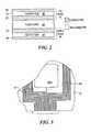
- the sensing sheet 12includes a number of layers laminated together.
- the sheet 12includes a multi-layer top sheet 42 , a multi-layer bottom sheet 44 , and a foam core 46 disposed therebetween.
- Both the top sheet 42 and bottom sheet 44include a layer of olefin film 48 approximately 0.0065′′ thick, such as sold by duPont, Inc. under the trademark TYVEK®. Both sides of each layer of film 48 are coated with conductive material.
- Each outer layer 50is a ground plane covering substantially the entire surface of the respective film 48 to provide shielding from electrical noise.
- Each inner layer 52has patterned conductive traces that define the sensing elements, as described in more detail below.
- the conductive layers 50 and 52are preferably made using conductive inks that are applied to the respective surfaces of the films 48 during manufacture of the sensing sheet 12 . These layers are approximately 0.001′′ thick.
- the inner layers 52are preferably made using a silver-based conductive ink for its excellent electrical properties.
- the outer layers 50may be made using a copper-based conductive ink, which will have suitable electrical properties and lower cost than a silver-based ink.
- the foam core 46is approximately 0.5′′ thick when uncompressed.
- the compression properties of the foam core 46can vary depending on the application, more specifically on the range of weights of the patient 10 being monitored.
- the compression properties of the foam core 46largely dictate the sensitivity of the sensors, which refers to the change in sensor capacitance due to changes in applied force. For adults in a normal weight range, it is desirable that the foam core 46 deflect about 25% when a pressure of 25 lbs. per square foot is applied.
- the useful upper limit of deflectionis approximately 50% of uncompressed thickness. If the sensing sheet 12 is to be used with a different class of patients 10 , such as infants for example, it may be desirable to use a foam core 46 having different compression characteristics so as to achieve optimal sensitivity.
- FIG. 3shows the top sheet 42 , specifically the surface on which the conductive layer 52 ( FIG. 2 ) is formed.
- the top sheet 42measures approximately 6.5 feet long by 3 feet wide.
- the conductive layer 52comprises a number of conductive planar elements referred to as “plates” 54 interconnected by a conductive trace 56 .
- a segment 58 of the trace 56is formed at the bottom of the sheet 42 for purposes of establishing an electrical interconnection between the trace 56 and a separate connector (not shown), as described in more detail below.
- the plates 54measure approximately 5′′ on a side.
- FIG. 4shows the bottom sheet 44 , specifically the surface on which the conductive layer 52 is formed.
- the bottom sheet 44also measures 6.5 feet by 3 feet.
- Conductive plates 60(shown as 60 - 1 through 60 - 8 ) are formed at respective positions corresponding to the positions of the plates 54 on the top sheet 42 (FIG. 3 ), so as to form eight plate capacitors when the sensing sheet 12 is assembled.
- the plates 60are connected to respective traces in a set 62 that extends to the bottom edge of the bottom sheet 44 .
- the traces 62are described in more detail below.
- a suitable drive signalsuch as a 5 volt peak-to-peak sine wave of 50 KHz is applied to the plates 54 of the top sheet 42 via the trace 56 formed thereon.
- This signalis capacitively coupled to each of the plates 60 of the bottom sheet 44 .
- the capacitance of each plate capacitor formed by a given plate 54 and its opposite plate 60changes in response to locally experienced forces that change the plate spacing by compressing the foam core 46 (FIG. 2 ).
- the respective strengths of the 50 KHz signals appearing on the plates 60vary accordingly, and these signals are sampled and processed by the SSPU 14 ( FIG. 1 ) as described above.
- different two-dimensional weightsare applied to the signals from the plates 60 to reflect their respective spatial characteristics, including location, size, and shape.
- These spatial weightsare chosen from a suitable two-dimensional space, such as a rectangular grid with vertices at ( 0 , 0 ), ( 0 , 1 ), ( 1 , 0 ) and ( 1 , 1 ).
- the plates 60are of uniform size and are distributed symmetrically on the surface of the bottom layer 44 .
- the spatial weights in the following tablemight be used, where each spatial weight corresponds to a different plate 60 as shown:
- FIG. 5shows the bottom edge of the bottom sheet 44 in more detail.
- the traces 62are arranged in two groups, one to the right of the bottom-most plate 60 and the other to the left.
- the right groupincludes seven individual traces, consisting of four ground traces interspersed with three signal traces, one for each of the three plates 60 on the right side of the sheet 44 (FIG. 4 ).
- the left groupincludes nine individual traces, consisting of five ground traces interspersed with four signal traces, one for the top-most plate 60 and one for each of the three plates 60 on the left side of the sheet 44 (FIG. 4 ).
- FIG. 6shows the manner in which connections are formed between the traces 62 and a cable 66 at the connection edge of the bottom sheet 44 .
- the traces 62are shown as signal traces 62 -S and ground traces 62 -G.
- Each conductor of the cable 66is provided with a solderless terminal 68 which is secured to the sheet 44 in contact with a corresponding signal trace 62 -S.
- a conductive snap 70is used to electrically couple each ground trace 62 -G to the ground plane on the opposite surface of the sheet. Specifically, a male component (not shown) of the snap 70 extends through a hole in the trace 62 -G and sheet 44 , and the male component is received by a female component (not shown) on the other side.
- each ground trace 62 -Git is generally desirable to place several such snaps 70 along the length of each ground trace 62 -G, to minimize stray impedance in the ground path that can contribute to noise. Also, it may be desirable that the snaps 70 and/or terminals 68 be epoxied to the sheet 44 for an even more secure attachment.
- FIG. 7shows the attachment of a conductive lead of the cable 66 to either sheet 42 or 44 in greater detail.
- a plastic rivet 72extends through a copper washer 74 , the sheet 42 or 44 , and the solderless terminal 68 as shown.
- a rivet head 76is placed over the rivet 72 , and the rivet 72 and rivet head 76 are then squeezed together in a conventional fashion. By this action, the terminal 68 makes secure connection to the conductive layer 52 of the sheet 42 , 44 .
- FIG. 8shows the area around a typical plate 60 .
- the plate 60is connected to a corresponding signal trace 62 -S, which is surrounded on both sides by ground traces 62 -G for shielding purposes.
- Each pair of ground traces 62 -Gextends alongside the entire run of the corresponding signal trace 62 -S from plate 60 to the bottom edge of the sheet 44 .
- FIG. 9shows a single-station process for manufacturing the sensing sheet 12 .
- a silk screening machineis set up with a roll of olefin film.
- the outer conductive layer 50( FIG. 2 ) is silk screened onto a length of film sufficient for 60 top sheets 42 and 60 bottom sheets 44 . Because the outer layer 50 is a ground plane extending across the entire surface of each sheet, this layer can be deposited as one continuous film along 780 feet (120 ⁇ 6.5) of the olefin film. After the layer 50 has been deposited, the individual sheets are cut as each 6.5′ length of film exits the machine.
- the sheetsare placed into an oven to allow the conductive ink to dry.
- the sheetsare then removed from the oven at step 86 .
- the patterned conductive layer 52is silk screened onto the 60 top sheets 42 , and these are returned to the oven for curing at step 90 .
- assembly machine and testing apparatuscan be set up in preparation for the final assembly and testing of the sheets 12 .
- the cured top sheets 42are removed from the oven, and at step 96 ground leads are “snapped” to the ground plane of the cured top sheets 42 using snaps as described above with reference to FIG. 6 .
- the patterned layer 52is silk screened onto the bottom sheets 44 .
- the bottom sheets 44are then placed in the oven for curing at step 100 , while at step 102 the top sheets 42 are moved to an assembly area and the press is set up for the bottom sheets 44 .
- ground leadsare snapped to the ground plane of the cured bottom sheets 44 , while at the same time at step 106 a cable assembly is riveted to each top sheet 42 .
- a cable assemblyis riveted to each bottom sheet 44 .
- each sheet 42 and 44is tested for continuity of connections, such as between each plate 60 and its associated trace 62 for example.
- Each sheetis also tested for the absence of any short circuits between the outer and inner layers 50 and 52 , which could occur for example if the conductive ink were to bleed through the olefin film. This testing is preferably done prior to the attachment of the cables. Once the cables are attached, additional testing is performed to ensure proper connectivity between the conductors of the cable and the various conductive elements on the sheet.
- the top and bottom sheets 42 and 44are assembled into the final sheet 12 .
- the core 46is pre-treated with a heat-activated adhesive on both surfaces, and then pressed together with the sheets 42 and 44 in a heated press. This process is illustrated in FIG. 10 , where the elements 114 are heated press elements.
- FIG. 11illustrates a process for manufacturing the sensing sheet 12 which follows more of an assembly line model than the process of FIG. 9 . It is assumed that there are separate workers at each station. Also, some of the equipment, such as the silk screening machines and cable assembly stations, are duplicated for improved throughput. The overall process reflected in steps 120 - 142 of FIG. 11 is generally the same as that shown in FIG. 9 . However, much greater volumes of sheets 12 can be produced due to the assembly line structure. Several batches of material are in process simultaneously, with each batch being in a different stage of completion. The process of FIG. 11 is capable of yielding approximately 210 finished sensing sheets 12 per day, whereas the single-person process of FIG. 9 can yield approximately 60 sheets per day.
Landscapes
- Health & Medical Sciences (AREA)
- Engineering & Computer Science (AREA)
- Life Sciences & Earth Sciences (AREA)
- Physics & Mathematics (AREA)
- General Physics & Mathematics (AREA)
- General Health & Medical Sciences (AREA)
- Veterinary Medicine (AREA)
- Heart & Thoracic Surgery (AREA)
- Medical Informatics (AREA)
- Molecular Biology (AREA)
- Surgery (AREA)
- Animal Behavior & Ethology (AREA)
- Biomedical Technology (AREA)
- Public Health (AREA)
- Pathology (AREA)
- Theoretical Computer Science (AREA)
- Biophysics (AREA)
- Physiology (AREA)
- Dentistry (AREA)
- Oral & Maxillofacial Surgery (AREA)
- Mathematical Physics (AREA)
- Mechanical Engineering (AREA)
- Human Computer Interaction (AREA)
- Multimedia (AREA)
- Microelectronics & Electronic Packaging (AREA)
- Computer Networks & Wireless Communication (AREA)
- Computer Vision & Pattern Recognition (AREA)
- Psychiatry (AREA)
- Social Psychology (AREA)
- Measuring And Recording Apparatus For Diagnosis (AREA)
Abstract
Description
This application is a continuation of U.S. patent application Ser. No. 09/791,114 filed Feb. 22, 2001, now U.S. Pat. No. 6,546,813; which is a continuation in part of U.S. patent application Ser. No. 09/169,759 filed Oct. 9, 1998, which issued May 1, 2001 as U.S. Pat. No. 6,223,606; which is a divisional of U.S. patent application Ser. No. 08/780,435 filed Jan. 8, 1997, which issued on Oct. 13, 1998 as U.S. Pat. No. 5,821,633.
Not Applicable
The present invention is related to the field of patient monitoring equipment.
Patient monitoring systems are used in many settings to assist medical personnel in providing care. In many settings, such as hospital wards and nursing homes, there can be problems associated with patients' getting out of bed without supervision or assistance. A patient may suffer a fall whose effects can range from minor to major. Older patients are at risk of breaking their hips in a fall, requiring extended bed rest and attendant problems. Systems have been known that monitor whether a patient is present in a bed or wheelchair. Essentially, these systems employ a flat sensor laid on the mattress or cushion, and electronic apparatus that responds to signals from the sensor. For example, the strength of a sensor output signal may be proportional to the weight applied to the sensor. The electronic apparatus therefore compares the sensor output signal with one or more predetermined values corresponding to significant thresholds of interest. For example, if the sensor output signal falls below a predetermined low value, the apparatus generates an indication that the patient has gotten out of bed.
Prior patient monitoring systems have used sensors having certain drawbacks that limit performance. One such drawback is size. Sensors to be used on a bed are as wide as the bed, but extend only about a foot in the longitudinal direction. These sensors are intended for placement in the middle of the bed, on the assumption that a patient's weight is concentrated there. However, a patient may move into a position away from the sensor, resulting in a false alarm. Existing sensors have also employed switches as sensing elements, which can provide only a binary indication. Due to the lack of resolution, only limited information can be obtained from the sensor.
In accordance with the present invention, a sensor-based patient monitoring system is disclosed incorporating features that overcome limitations of the prior art. In addition to having superior performance for traditional uses, such as reducing the incidence of patient falls, the system can be used for a variety of other clinical purposes to assist medical personnel and enhance the quality of care.
The system includes a replaceable laminar sensor placed on a bed or similar surface, the sensor including distributed force sensing elements providing output signals to processing apparatus for processing the force distribution information. The processing apparatus includes a near-bed processor and a central processor coupled to the near-bed processor by a wireless communication link. The processing apparatus applies spatial weighting to the sensor output signals to derive the force distribution across the sensor, and processes the force distribution information over time to generate pertinent patient status information. The information can vary depending on the operational purpose for the monitoring. For example, the information can include patient presence, position, agitation, seizure activity, or respiration. The information can be used to generate a display at a central monitoring station, and to update medical databases coupled to the central processor. The information can also be provided to a paging system to alert attending medical personnel.
The disclosed laminar sensor is made of layers of olefin film having patterns of conductive ink deposited thereon to form capacitive sensing elements, ground planes, and signal traces. The layers are laminated with a foam core selected to provide desired sensitivity of the capacitive sensing elements for a range of expected patient weights. Both a low-cost process and a high-volume process for manufacturing the sensor are shown.
Other aspects, features, and advantages of the present invention are disclosed in the detailed description that follows.
The invention is more fully understood by reference to the following Detailed Description in conjunction with the Drawing, of which:
The disclosure of U.S. patent application Ser. No. 09/169,759, filed Oct. 9, 1998 and entitled Center Of Weight Sensor, is hereby incorporated by reference herein.
InFIG. 1 , the motion of apatient 10 is transmitted to asensing sheet 12 by direct physical contact, such as exists when thesensing sheet 12 is placed on a bed and thepatient 10 lies on top of thesensing sheet 12. Thesensing sheet 12 includes a number of spaced-apart sensing elements or transducers (not shown inFIG. 1 ) capable of converting applied forces into an electrical signals representative of the forces. One example of such asensing sheet 12, described in detail below, employs sensing elements that function as variable capacitors whose capacitance changes in response to applied forces. Other types of sensing elements may also be employed, such as piezoelectric sensing elements, force-sensing resistors, etc.
The signals generated by thesensing sheet 12 are communicated to a nearby sensor signal processing unit (SSPU)14. Theunit 14 contains analog-to-digital (A/D)converters 16, asignal processor 18, and a radio-frequency (RF)modem 20. The A/D converters 16 continually translate the analog signals from thesensing sheet 12 into corresponding digital values. Thesignal processor 18 applies spatial weighting to the digital output streams from the A/D converters 16 to reflect the respective locations of the sensing elements on thesensing sheet 12, and uses the spatially-weighted digital signal streams in performing one or more analysis processes. Spatial weighting is described further below.
In general, theprocessor 18 monitors the outputs of the sensing elements to detect the occurrence of certain predetermined “patient states” that pertain to a particular analysis being performed. Generally, the patient states are defined by one or more thresholds associated with certain analysis variables. For example, an analysis process for determining whether thepatient 10 is present may simply integrate the force distribution over thesensing sheet 12, as reported by the various sensing elements, and compare the integrated value with a predetermined threshold representing the minimum value that would be expected if a patient were present. Appropriate values to use for the threshold can be determined analytically or empirically. There may be a selectable threshold based on certain parameters, such as the patient's weight.
Much more sophisticated analysis processes can also be performed. Analyses may also include time as a parameter. For example, an analysis process may be used to help reduce the incidence of bedsores, which can develop if a patient remains in a given position too long. The movement of the center of the patient's mass over time can be monitored, and appropriate action taken when the extent of movement is less than a predetermined threshold for more than a predetermined time. Processes may be employed for detecting and providing information about patient agitation, respiration, reaction to drugs, sleep disorders, or seizures. The system can also be used to enhance patient safety and security. By monitoring weight changes on a patient's bed, the system can provide an indication that a patient has gotten up, or that an additional person is on the bed.
When significant patient states or state transitions are detected by theprocessor 18, a corresponding information message is generated by theprocessor 18 and transmitted on a wireless communications link22 via theRF modem 20. In general, the information message contains information identifying the patient, such as the patient's name, room number, etc., and information about the detected patient state. In addition, theprocessor 18 may also update a local data collection log (not shown) maintained for administrative or diagnostic purposes.
In the illustrated system, it is desirable that the RF modem function as a “slave” with respect to a “master ”modem 24 residing in a central information-processing unit (CIPU)26. Because theCIPU 26 communicates with a number of SSPUs14, it would be inefficient to continually maintainindividual communications links 22 between theCIPU 26 and eachSSPU 14. By employing a master-slave arrangement, alink 22 is in existence only when needed. When theslave modem 20 receives a message from theprocessor 18, it requests a connection with themaster modem 24 using a separate, low-rate signaling channel (not shown). Themaster modem 24 informs theslave modem 20 when thelink 22 has been established, whereupon theslave modem 20 transmits the information message. Preferably, themaster modem 24 transmits a positive acknowledgement message to theslave modem 20 if the information message is received correctly.
It may be desirable that themaster modem 24 also be capable of initiating the establishment of thelink 22. This capability can be useful, for example, when configuration information, updates, or other information is to be transferred from theCIPU 26 to theSSPU 14. When directed by themaster modem 24, theslave modem 20 monitors thelink 22 for incoming messages containing such information and forwards these messages to theprocessor 18. Software executing in theprocessor 18 responds in a desired predetermined fashion.
When a patient state information message is received at theCIPU 26, the data is used to update acentral database archive 30 and is also provided to auser interface platform 32. The information in thedatabase archive 30 can be used for a variety of generally offline activities, such as administrative record keeping, statistics gathering, etc. Theuser interface platform 32 provides the information to one or more real-time users, who in general are medical personnel responsible for the care of thepatient 10. For example, theplatform 32 may include a graphical display at a nurses' desk to provide the information to adesk nurse 34. Theplatform 32 may also include paging equipment programmed to send an alert message to afloor nurse 36 or other personnel. The alert message preferably includes patient identifying information, such as the identity and room number of thepatient 10, and a brief description of the detected patient state. For example, when a “patient not present” state is detected, an alert message such as “Jones, 302, Out Of Bed” may be generated.
As shown, theCIPU 26 may also communicate with other entities via a local- or wide-area network. There may be inter-departmental communications withother departments 38 of a medical facility, such communications typically occurring over a local-area network. Examples include communications with medical laboratories and administrative offices such as a patient billing department. There may also be wider-area communications withremote entities 40, such as a patient's family, affiliated research facilities, physicians' offices, and insurance companies, for example.
As a scaled-back alternative to the system ofFIG. 1 , theSSPU 14 may itself include a pager (not shown) in place of theslave RF modem 20, and the CIPU26 and its network connections dispensed with. In such a system, theSSPU 14 itself sends a paging signal to thedesk nurse 34,floor nurse 36, or other personnel as appropriate. While such a system has overall less functionality than the system ofFIG. 1 , it retains the important core functions of thesensing sheet 12 andSSPU 14, and can provide greater cost effectiveness and flexibility in deployment. Of course, other system configurations are also possible.
As shown inFIG. 2 , thesensing sheet 12 includes a number of layers laminated together. Thesheet 12 includes a multi-layertop sheet 42, amulti-layer bottom sheet 44, and afoam core 46 disposed therebetween. Both thetop sheet 42 andbottom sheet 44 include a layer ofolefin film 48 approximately 0.0065″ thick, such as sold by duPont, Inc. under the trademark TYVEK®. Both sides of each layer offilm 48 are coated with conductive material. Eachouter layer 50 is a ground plane covering substantially the entire surface of therespective film 48 to provide shielding from electrical noise. Eachinner layer 52 has patterned conductive traces that define the sensing elements, as described in more detail below.
Theconductive layers films 48 during manufacture of thesensing sheet 12. These layers are approximately 0.001″ thick. Theinner layers 52 are preferably made using a silver-based conductive ink for its excellent electrical properties. Theouter layers 50 may be made using a copper-based conductive ink, which will have suitable electrical properties and lower cost than a silver-based ink.
Thefoam core 46 is approximately 0.5″ thick when uncompressed. The compression properties of thefoam core 46 can vary depending on the application, more specifically on the range of weights of the patient10 being monitored. The compression properties of thefoam core 46 largely dictate the sensitivity of the sensors, which refers to the change in sensor capacitance due to changes in applied force. For adults in a normal weight range, it is desirable that thefoam core 46 deflect about 25% when a pressure of 25 lbs. per square foot is applied. The useful upper limit of deflection is approximately 50% of uncompressed thickness. If thesensing sheet 12 is to be used with a different class ofpatients 10, such as infants for example, it may be desirable to use afoam core 46 having different compression characteristics so as to achieve optimal sensitivity.
In operation, a suitable drive signal such as a 5 volt peak-to-peak sine wave of 50 KHz is applied to theplates 54 of thetop sheet 42 via thetrace 56 formed thereon. This signal is capacitively coupled to each of theplates 60 of thebottom sheet 44. The capacitance of each plate capacitor formed by a givenplate 54 and itsopposite plate 60 changes in response to locally experienced forces that change the plate spacing by compressing the foam core46 (FIG.2). As a result, the respective strengths of the 50 KHz signals appearing on theplates 60 vary accordingly, and these signals are sampled and processed by the SSPU14 (FIG. 1 ) as described above. In particular, different two-dimensional weights are applied to the signals from theplates 60 to reflect their respective spatial characteristics, including location, size, and shape. These spatial weights are chosen from a suitable two-dimensional space, such as a rectangular grid with vertices at (0,0), (0,1), (1,0) and (1,1). For thesheet 12 as shown herein, theplates 60 are of uniform size and are distributed symmetrically on the surface of thebottom layer 44. In this case, the spatial weights in the following table might be used, where each spatial weight corresponds to adifferent plate 60 as shown:
| Plate | X | Y |
| 60-1 | 0.2 | 0.3 |
| 60-2 | 0.2 | 0.7 |
| 60-3 | 0.4 | 0.5 |
| 60-4 | 0.5 | 0.1 |
| 60-5 | 0.5 | 0.9 |
| 60-6 | 0.6 | 0.5 |
| 60-7 | 0.8 | 0.3 |
| 60-8 | 0.8 | 0.7 |
Atstep 84, the sheets are placed into an oven to allow the conductive ink to dry. The sheets are then removed from the oven atstep 86. Atstep 88, the patternedconductive layer 52 is silk screened onto the60top sheets 42, and these are returned to the oven for curing atstep 90. At the same time, at step92 a press, assembly machine and testing apparatus can be set up in preparation for the final assembly and testing of thesheets 12.
Atstep 94, the curedtop sheets 42 are removed from the oven, and atstep 96 ground leads are “snapped” to the ground plane of the curedtop sheets 42 using snaps as described above with reference to FIG.6. At the same time, atstep 98 the patternedlayer 52 is silk screened onto thebottom sheets 44. Thebottom sheets 44 are then placed in the oven for curing atstep 100, while atstep 102 thetop sheets 42 are moved to an assembly area and the press is set up for thebottom sheets 44. Atstep 104, ground leads are snapped to the ground plane of the curedbottom sheets 44, while at the same time at step106 a cable assembly is riveted to eachtop sheet 42. Atstep 108, a cable assembly is riveted to eachbottom sheet 44.
Atstep 110, eachsheet plate 60 and its associatedtrace 62 for example. Each sheet is also tested for the absence of any short circuits between the outer andinner layers
Atstep 112 the top andbottom sheets final sheet 12. Thecore 46 is pre-treated with a heat-activated adhesive on both surfaces, and then pressed together with thesheets FIG. 10 , where theelements 114 are heated press elements.
A patient monitoring system employing a laminar sensor sheet has been shown. It will be apparent to those skilled in the art that modifications to and variations of the disclosed methods and apparatus are possible without departing from the inventive concepts disclosed herein, and therefore the invention should not be viewed as limited except to the full scope and spirit of the appended claims.
Claims (18)
1. A system for sensing status of a patient in a bed comprising:
a replaceable laminar sensor on said bed;
said laminar sensor having a plurality of force sensing elements distributed two-dimensionally throughout said sensor; and
processing apparatus responsive to forces sensed by said sensor for forming a spatially weighted sum of the forces sensed by said sensor to provide a distribution of the forces throughout said laminar sensor, said processing apparatus providing an indication over time of a patient status in response to said weighted average.
2. The system ofclaim 1 wherein said laminar sensor comprises a sheet having discrete sensors therein.
3. The system ofclaim 2 wherein said discrete sensors include one of capacitive sensors, piezoelectric sensors, and resistive sensors.
4. The system ofclaim 1 wherein said laminar sensor further includes conductors extending from the discrete sensors to a connection point at an edge of said sheet.
5. The system ofclaim 2 wherein said sheet is dimensioned to cover said bed over a predetermined range of patient movement.
6. The system ofclaim 1 wherein said processing apparatus includes a near-bed processor and a central processor in communication with said near-bed processor through a communication link.
7. The system ofclaim 6 wherein said communication link is a wireless link having interfaces at said near-bed processor and said central processor.
8. The system ofclaim 1 wherein said processing apparatus provides patient status information including information regarding patient presence, patient position, patient agitation, patient seizures, patient respiration, and patient security.
9. The system ofclaim 1 wherein said processing apparatus provides patient status information relative to sleep disorders.
10. The system ofclaim 1 wherein said processing apparatus provides patient status information relative to patient drug reactions.
11. The system ofclaim 1 wherein said processing apparatus provides information relative to the presence or absence of patient activity sufficient to avoid bed sores.
12. The system ofclaim 1 further including a database for recording patient status.
13. The system ofclaim 12 wherein said processing apparatus provides adaptive indications of patient status in response to database information and sensor signals.
14. A sensing sheet for use in a patient monitoring system, the patient monitoring system including processing apparatus operative to calculate a spatially weighted sum of the respective values of sensor signals generated by the sensing sheet, the spatially weighted sum being calculated using a set of predetermined two-dimensional spatial weight values, the sensing sheet comprising:
a planar, flexible, electrically insulative substrate, the substrate having length and width substantially corresponding to the length and width of a patient's bed; and
a pattern of sensing elements on the substrate, the sensing elements being spaced apart to define a two-dimensional sensing area on the patient's bed when the sensing sheet is placed thereon, the sensing elements having respective sizes, shapes and locations in relation to the predetermined two-dimensional spatial weight values such that the spatially weighted sum accurately reflects the spatial distribution of forces existing between a patient and the patient's bed when the sensing sheet is disposed therebetween.
15. A sensing sheet according toclaim 14 , wherein the substrate includes a set of laminated layers.
16. A sensing sheet according toclaim 14 , wherein the sensing elements comprise capacitors made from conductive planar elements disposed on the substrate.
17. A sensing sheet for use in a patient monitoring system, the patient monitoring system including processing apparatus operative to calculate a spatially weighted sum of the respective values of sensor signals generated by the sensing sheet, the spatially weighted sum being calculated using a set of predetermined two-dimensional spatial weight values, the sensing sheet comprising:
a first electrically insulative film, the first film having length and width substantially corresponding to the length and width of a patient's bed and having a pattern of conductive electrodes formed thereon, the conductive electrodes being spaced apart on the film to define a two-dimensional sensing area extending substantially entirely across the patient's bed when the sensing sheet is placed thereon, the conductive electrodes having respective sizes, shapes and locations in relation to the predetermined two-dimensional spatial weight values such that the spatially weighted sum accurately reflects the spatial distribution of forces existing between a patient and the patient's bed when the sensing sheet is disposed therebetween, the first film also including a set of conductive traces creating individual conductive paths from the electrodes to a connection area of the sensing sheet;
a second electrically insulative film laminated with the first film, the second film having length and width substantially the same as the length and width of the first film, the second film having a pattern of conductive electrodes formed thereon at respective locations directly opposite the respective locations of the electrodes on the first film, the second film also including conductive traces operative to electrically interconnect all of the conductive electrodes on the second film to each other and to the connection area of the sensing sheet; and
a multi-conductor cable extending from the connection area of the sensing sheet and including a multi-terminal connector, the conductors of the cable being operative to create respective conductive paths from respective conductive traces of the first and second films to respective terminals of the multi-terminal connector.
18. A sensing sheet according toclaim 17 , wherein the signal traces are shielded by corresponding ground traces.
Priority Applications (1)
| Application Number | Priority Date | Filing Date | Title |
|---|---|---|---|
| US10/378,340US6840117B2 (en) | 1997-01-08 | 2003-03-03 | Patient monitoring system employing array of force sensors on a bedsheet or similar substrate |
Applications Claiming Priority (4)
| Application Number | Priority Date | Filing Date | Title |
|---|---|---|---|
| US08/780,435US5821633A (en) | 1997-01-08 | 1997-01-08 | Center of weight sensor |
| US09/169,759US6223606B1 (en) | 1997-01-08 | 1998-10-09 | Center of weight sensor |
| US09/791,114US6546813B2 (en) | 1997-01-08 | 2001-02-22 | Patient monitoring system employing array of force sensors on a bedsheet or similar substrate |
| US10/378,340US6840117B2 (en) | 1997-01-08 | 2003-03-03 | Patient monitoring system employing array of force sensors on a bedsheet or similar substrate |
Related Parent Applications (1)
| Application Number | Title | Priority Date | Filing Date |
|---|---|---|---|
| US09/791,114ContinuationUS6546813B2 (en) | 1997-01-08 | 2001-02-22 | Patient monitoring system employing array of force sensors on a bedsheet or similar substrate |
Publications (2)
| Publication Number | Publication Date |
|---|---|
| US20030136201A1 US20030136201A1 (en) | 2003-07-24 |
| US6840117B2true US6840117B2 (en) | 2005-01-11 |
Family
ID=25152730
Family Applications (2)
| Application Number | Title | Priority Date | Filing Date |
|---|---|---|---|
| US09/791,114Expired - LifetimeUS6546813B2 (en) | 1997-01-08 | 2001-02-22 | Patient monitoring system employing array of force sensors on a bedsheet or similar substrate |
| US10/378,340Expired - LifetimeUS6840117B2 (en) | 1997-01-08 | 2003-03-03 | Patient monitoring system employing array of force sensors on a bedsheet or similar substrate |
Family Applications Before (1)
| Application Number | Title | Priority Date | Filing Date |
|---|---|---|---|
| US09/791,114Expired - LifetimeUS6546813B2 (en) | 1997-01-08 | 2001-02-22 | Patient monitoring system employing array of force sensors on a bedsheet or similar substrate |
Country Status (2)
| Country | Link |
|---|---|
| US (2) | US6546813B2 (en) |
| WO (1) | WO2002068921A2 (en) |
Cited By (68)
| Publication number | Priority date | Publication date | Assignee | Title |
|---|---|---|---|---|
| US20050131578A1 (en)* | 2003-09-30 | 2005-06-16 | Intrinsic Marks International Llc | Item monitoring system and methods |
| US20050190068A1 (en)* | 2004-02-18 | 2005-09-01 | Gentry Jason M. | Method and system for integrating a passive sensor array with a mattress for patient monitoring |
| US20060220657A1 (en)* | 2005-04-04 | 2006-10-05 | 3M Innovative Properties Company | Sensor assembly and method of forming the same |
| US20070210917A1 (en)* | 2004-08-02 | 2007-09-13 | Collins Williams F Jr | Wireless bed connectivity |
| US7319386B2 (en) | 2004-08-02 | 2008-01-15 | Hill-Rom Services, Inc. | Configurable system for alerting caregivers |
| WO2008039082A3 (en)* | 2006-09-25 | 2008-06-26 | Zephyr Technology Ltd | Bio-mechanical sensor system |
| US20080224861A1 (en)* | 2003-08-21 | 2008-09-18 | Mcneely Craig A | Hospital bed having wireless data capability |
| US20090056027A1 (en)* | 2007-08-29 | 2009-03-05 | Hill-Rom Services, Inc. | Mattress for a hospital bed for use in a healthcare facility and management of same |
| US20090089933A1 (en)* | 2007-10-09 | 2009-04-09 | Sealy Technology, Llc | Pressure dispersion support systems |
| US20090099480A1 (en)* | 2007-05-24 | 2009-04-16 | Peter Salgo | System and method for patient monitoring |
| US20090157056A1 (en)* | 2007-12-18 | 2009-06-18 | Searete Llc, A Limited Liability Corporation Of The State Of Delaware | Circulatory monitoring systems and methods |
| US20090157171A1 (en)* | 2007-12-18 | 2009-06-18 | Searete Llc, A Limited Liability Corporation Of The State Of Delaware | Treatment indications informed by a priori implant information |
| US20090212925A1 (en)* | 2008-02-22 | 2009-08-27 | Schuman Sr Richard Joseph | User station for healthcare communication system |
| US20090287094A1 (en)* | 2008-05-15 | 2009-11-19 | Seacrete Llc, A Limited Liability Corporation Of The State Of Delaware | Circulatory monitoring systems and methods |
| US20090287101A1 (en)* | 2008-05-13 | 2009-11-19 | Searete Llc, A Limited Liability Corporation Of The State Of Delaware | Circulatory monitoring systems and methods |
| US20090287109A1 (en)* | 2008-05-14 | 2009-11-19 | Searete Llc, A Limited Liability Corporation Of The State Of Delaware | Circulatory monitoring systems and methods |
| US20090287191A1 (en)* | 2007-12-18 | 2009-11-19 | Searete Llc, A Limited Liability Corporation Of The State Of Delaware | Circulatory monitoring systems and methods |
| US20090292212A1 (en)* | 2008-05-20 | 2009-11-26 | Searete Llc, A Limited Corporation Of The State Of Delaware | Circulatory monitoring systems and methods |
| US20090289800A1 (en)* | 2005-05-31 | 2009-11-26 | Ole Hansen | Device for a bed alarm |
| US20090318773A1 (en)* | 2008-06-24 | 2009-12-24 | Searete Llc, A Limited Liability Corporation Of The State Of Delaware | Involuntary-response-dependent consequences |
| US20100056873A1 (en)* | 2008-08-27 | 2010-03-04 | Allen Paul G | Health-related signaling via wearable items |
| US20100052892A1 (en)* | 2008-08-27 | 2010-03-04 | Searete Llc, A Limited Liability Corporation Of The State Of Delaware | Health-related signaling via wearable items |
| US20100052898A1 (en)* | 2008-08-27 | 2010-03-04 | Searete Llc, A Limited Liability Corporation Of The State Of Delaware | Health-related signaling via wearable items |
| US20100052897A1 (en)* | 2008-08-27 | 2010-03-04 | Allen Paul G | Health-related signaling via wearable items |
| US20100225489A1 (en)* | 2009-03-06 | 2010-09-09 | Telehealth Sensors, Llc | Mattress or Chair Sensor Envelope with an Antenna |
| US20100228516A1 (en)* | 2009-03-06 | 2010-09-09 | Telehealth Sensors, Llc | Electronic mattress or chair sensor for patient monitoring |
| US20100225488A1 (en)* | 2009-03-06 | 2010-09-09 | Telehealth Sensors, Llc | Patient Monitoring System Using an Active Mattress or Chair System |
| US7868740B2 (en) | 2007-08-29 | 2011-01-11 | Hill-Rom Services, Inc. | Association of support surfaces and beds |
| US20110205062A1 (en)* | 2010-02-19 | 2011-08-25 | Pesot Whitney W | Nurse call system with additional status board |
| US8161826B1 (en) | 2009-03-05 | 2012-04-24 | Stryker Corporation | Elastically stretchable fabric force sensor arrays and methods of making |
| US8284046B2 (en) | 2008-08-27 | 2012-10-09 | The Invention Science Fund I, Llc | Health-related signaling via wearable items |
| US8533879B1 (en) | 2008-03-15 | 2013-09-17 | Stryker Corporation | Adaptive cushion method and apparatus for minimizing force concentrations on a human body |
| US8636670B2 (en) | 2008-05-13 | 2014-01-28 | The Invention Science Fund I, Llc | Circulatory monitoring systems and methods |
| US20140059778A1 (en)* | 2012-08-30 | 2014-03-06 | Ronald B. Jalbert | Interface pressure sensing mattress |
| US8904876B2 (en) | 2012-09-29 | 2014-12-09 | Stryker Corporation | Flexible piezocapacitive and piezoresistive force and pressure sensors |
| US8997588B2 (en) | 2012-09-29 | 2015-04-07 | Stryker Corporation | Force detecting mat with multiple sensor types |
| US20150283923A1 (en)* | 2012-11-19 | 2015-10-08 | Iee International Electronics & Engineering S.A. | Seat occupancy sensor unit at a lower b-surface side of a seat cushion |
| WO2016060749A1 (en)* | 2013-08-31 | 2016-04-21 | Alpha Omega Neuro Technologies Ltd. | Surgical drape, evoked response probes and their methods of use |
| US9370457B2 (en) | 2013-03-14 | 2016-06-21 | Select Comfort Corporation | Inflatable air mattress snoring detection and response |
| US9392879B2 (en) | 2013-03-14 | 2016-07-19 | Select Comfort Corporation | Inflatable air mattress system architecture |
| US9411934B2 (en) | 2012-05-08 | 2016-08-09 | Hill-Rom Services, Inc. | In-room alarm configuration of nurse call system |
| US9445751B2 (en) | 2013-07-18 | 2016-09-20 | Sleepiq Labs, Inc. | Device and method of monitoring a position and predicting an exit of a subject on or from a substrate |
| US9504416B2 (en) | 2013-07-03 | 2016-11-29 | Sleepiq Labs Inc. | Smart seat monitoring system |
| US9510688B2 (en) | 2013-03-14 | 2016-12-06 | Select Comfort Corporation | Inflatable air mattress system with detection techniques |
| US9539155B2 (en) | 2012-10-26 | 2017-01-10 | Hill-Rom Services, Inc. | Control system for patient support apparatus |
| US9635953B2 (en) | 2013-03-14 | 2017-05-02 | Sleepiq Labs Inc. | Inflatable air mattress autofill and off bed pressure adjustment |
| US9734293B2 (en) | 2007-10-26 | 2017-08-15 | Hill-Rom Services, Inc. | System and method for association of patient care devices to a patient |
| US9770114B2 (en) | 2013-12-30 | 2017-09-26 | Select Comfort Corporation | Inflatable air mattress with integrated control |
| US9830424B2 (en) | 2013-09-18 | 2017-11-28 | Hill-Rom Services, Inc. | Bed/room/patient association systems and methods |
| US9844275B2 (en) | 2013-03-14 | 2017-12-19 | Select Comfort Corporation | Inflatable air mattress with light and voice controls |
| US9875633B2 (en) | 2014-09-11 | 2018-01-23 | Hill-Rom Sas | Patient support apparatus |
| US10058467B2 (en) | 2013-03-14 | 2018-08-28 | Sleep Number Corporation | Partner snore feature for adjustable bed foundation |
| US10092242B2 (en) | 2015-01-05 | 2018-10-09 | Sleep Number Corporation | Bed with user occupancy tracking |
| US10136815B2 (en) | 2012-09-24 | 2018-11-27 | Physio-Control, Inc. | Patient monitoring device with remote alert |
| US10149549B2 (en) | 2015-08-06 | 2018-12-11 | Sleep Number Corporation | Diagnostics of bed and bedroom environment |
| US10182661B2 (en) | 2013-03-14 | 2019-01-22 | Sleep Number Corporation and Select Comfort Retail Corporation | Inflatable air mattress alert and monitoring system |
| US10325470B2 (en) | 2017-09-26 | 2019-06-18 | Citrix Systems, Inc. | System for monitoring health status of a person within an enclosed area |
| US10448749B2 (en) | 2014-10-10 | 2019-10-22 | Sleep Number Corporation | Bed having logic controller |
| US10674832B2 (en) | 2013-12-30 | 2020-06-09 | Sleep Number Corporation | Inflatable air mattress with integrated control |
| US11360470B2 (en)* | 2018-10-05 | 2022-06-14 | Thomas A. Youmans | Apparatus for detecting tilt, lean, movement, rotation, of a user, rider, payload |
| US11439345B2 (en) | 2006-09-22 | 2022-09-13 | Sleep Number Corporation | Method and apparatus for monitoring vital signs remotely |
| US11504061B2 (en) | 2017-03-21 | 2022-11-22 | Stryker Corporation | Systems and methods for ambient energy powered physiological parameter monitoring |
| US11737938B2 (en) | 2017-12-28 | 2023-08-29 | Sleep Number Corporation | Snore sensing bed |
| US11911325B2 (en) | 2019-02-26 | 2024-02-27 | Hill-Rom Services, Inc. | Bed interface for manual location |
| US12186241B2 (en) | 2021-01-22 | 2025-01-07 | Hill-Rom Services, Inc. | Time-based wireless pairing between a medical device and a wall unit |
| US12251243B2 (en) | 2008-02-22 | 2025-03-18 | Hill-Rom Services, Inc. | Distributed healthcare communication system |
| US12279999B2 (en) | 2021-01-22 | 2025-04-22 | Hill-Rom Services, Inc. | Wireless configuration and authorization of a wall unit that pairs with a medical device |
| US12390379B2 (en) | 2017-12-28 | 2025-08-19 | Sleep Number Corporation | Bed having snore detection feature |
Families Citing this family (43)
| Publication number | Priority date | Publication date | Assignee | Title |
|---|---|---|---|---|
| US6546813B2 (en)* | 1997-01-08 | 2003-04-15 | The Trustees Of Boston University | Patient monitoring system employing array of force sensors on a bedsheet or similar substrate |
| US8894577B2 (en)* | 1999-11-05 | 2014-11-25 | Elite Care Technologies, Inc. | System and method for medical information monitoring and processing |
| US6524239B1 (en)* | 1999-11-05 | 2003-02-25 | Wcr Company | Apparatus for non-instrusively measuring health parameters of a subject and method of use thereof |
| US20030010345A1 (en)* | 2002-08-02 | 2003-01-16 | Arthur Koblasz | Patient monitoring devices and methods |
| US20050076715A1 (en)* | 2003-10-13 | 2005-04-14 | Kuklis Matthew M. | Shear sensor apparatus |
| US7027949B2 (en)* | 2003-12-22 | 2006-04-11 | The Boeing Company | Systems and methods for measuring component matching |
| FI120961B (en)* | 2004-07-01 | 2010-05-31 | Emfit Oy | Method and apparatus for measuring and monitoring vital signs or presence |
| DE102005004142A1 (en)* | 2005-01-28 | 2006-08-10 | Siemens Ag | System or method for examining a patient by means of an imaging medical diagnostic device |
| DE102005008591A1 (en)* | 2005-02-24 | 2006-09-14 | Siemens Ag | Seat occupancy detection mat |
| JP5021625B2 (en)* | 2005-04-20 | 2012-09-12 | コーニンクレッカ フィリップス エレクトロニクス エヌ ヴィ | Patient monitoring system |
| US7430925B2 (en)* | 2005-05-18 | 2008-10-07 | Pressure Profile Systems, Inc. | Hybrid tactile sensor |
| US7541935B2 (en) | 2005-05-19 | 2009-06-02 | Proacticare Llc | System and methods for monitoring caregiver performance |
| JP5253156B2 (en)* | 2005-06-07 | 2013-07-31 | コーニンクレッカ フィリップス エレクトロニクス エヌ ヴィ | Patient monitoring system and method |
| US7740588B1 (en)* | 2005-06-24 | 2010-06-22 | Michael Sciarra | Wireless respiratory and heart rate monitoring system |
| WO2008024561A2 (en)* | 2006-07-05 | 2008-02-28 | Stryker Corporation | A system for detecting and monitoring vital signs |
| EP2083685A1 (en)* | 2006-11-29 | 2009-08-05 | Huntleigh Technology Limited | Patient monitoring system |
| CN101621963B (en)* | 2007-02-28 | 2012-05-23 | 皇家飞利浦电子股份有限公司 | System and method for obtaining physiological data of a patient |
| CN101662984B (en) | 2007-04-24 | 2013-10-30 | 皇家飞利浦电子股份有限公司 | Sensor arrangement and method for monitoring physiological parameters |
| US8535223B2 (en)* | 2008-02-28 | 2013-09-17 | Koninklijke Philips N.V. | Wireless patient monitoring using streaming of medical data with body-coupled communication |
| DE102009010379B4 (en)* | 2008-03-03 | 2013-04-18 | Dieter Martin | Method for monitoring a person lying in a bed |
| US8890937B2 (en) | 2009-06-01 | 2014-11-18 | The Curators Of The University Of Missouri | Anonymized video analysis methods and systems |
| JP2013522588A (en) | 2010-03-12 | 2013-06-13 | エンハンスド サーフェイス ダイナミクス,インコーポレイテッド | System and method for fast collection of data from pressure sensors in a pressure sensing system |
| WO2013008187A1 (en) | 2011-07-13 | 2013-01-17 | Enhanced Surface Dynamics, Inc. | Methods and systems for the manufacture and initiation of a pressure detection mat |
| WO2013033524A2 (en) | 2011-08-31 | 2013-03-07 | The Curators Of The University Of Missouri | Hydraulic bed sensor and system for non-invasive monitoring of physiological data |
| CN104219999A (en)* | 2012-01-30 | 2014-12-17 | 感官系统公司 | Sensors, interfaces and sensor systems for data collection and integrated remote monitoring of conditions at or near body surfaces |
| US8942800B2 (en) | 2012-04-20 | 2015-01-27 | Cardiac Science Corporation | Corrective prompting system for appropriate chest compressions |
| US10292605B2 (en) | 2012-11-15 | 2019-05-21 | Hill-Rom Services, Inc. | Bed load cell based physiological sensing systems and methods |
| DE102013213219B4 (en)* | 2013-07-05 | 2021-12-23 | Siemens Healthcare Gmbh | Device for determining deformation information for a board loaded with a load |
| FR3008874B1 (en)* | 2013-07-24 | 2016-07-29 | Comatel Casuel | IMPROVED SEAT ELEMENT FOR SEAT |
| TWI554304B (en)* | 2014-11-07 | 2016-10-21 | Yu-Han Chen | Projection capacitive body motion detection system |
| US20160174899A1 (en) | 2014-12-19 | 2016-06-23 | Withings | Wireless Connected Indoors Slipper and Wireless Connected Footwear and Associated Detection Methods |
| US10206630B2 (en) | 2015-08-28 | 2019-02-19 | Foresite Healthcare, Llc | Systems for automatic assessment of fall risk |
| US11864926B2 (en) | 2015-08-28 | 2024-01-09 | Foresite Healthcare, Llc | Systems and methods for detecting attempted bed exit |
| DE102015218298B3 (en)* | 2015-09-23 | 2017-02-23 | Siemens Healthcare Gmbh | An assembly comprising a patient support device with a support plate and a support for the support plate |
| US10453202B2 (en) | 2016-06-28 | 2019-10-22 | Foresite Healthcare, Llc | Systems and methods for use in detecting falls utilizing thermal sensing |
| US11083418B2 (en) | 2016-11-04 | 2021-08-10 | Wellsense, Inc. | Patient visualization system |
| US10492734B2 (en) | 2016-11-04 | 2019-12-03 | Wellsense, Inc. | Patient visualization system |
| US10739184B2 (en)* | 2017-06-30 | 2020-08-11 | Tesla, Inc. | Vehicle occupant classification systems and methods |
| CN107331118B (en)* | 2017-07-05 | 2020-11-17 | 浙江宇视科技有限公司 | Fall detection method and device |
| US10955301B2 (en) | 2017-10-17 | 2021-03-23 | University Of Maryland, College Park | Two-dimensional center of pressure sensor systems, devices, and methods |
| WO2019127539A1 (en)* | 2017-12-29 | 2019-07-04 | Shenzhen United Imaging Healthcare Co., Ltd. | Systems and methods for determining region of interest in medical imaging |
| WO2019127385A1 (en) | 2017-12-29 | 2019-07-04 | Shenzhen United Imaging Healthcare Co., Ltd. | Systems and methods for patient positioning |
| DE102019219532A1 (en)* | 2019-12-13 | 2021-06-17 | Robert Bosch Gmbh | Control system for a medical device |
Citations (29)
| Publication number | Priority date | Publication date | Assignee | Title |
|---|---|---|---|---|
| US3599199A (en) | 1968-12-06 | 1971-08-10 | Bunting Sterisystems Inc | System for simultaneously indicating a unit status at a plurality of stations |
| US4135241A (en) | 1971-02-22 | 1979-01-16 | Medelco, Incorporated | Inventory control, bed allocation and accounting data handling system |
| US4583084A (en) | 1984-01-27 | 1986-04-15 | Lutheran General Hospital, Inc. | Patient monitor |
| EP0222640A2 (en) | 1985-10-10 | 1987-05-20 | Barry J. French | Impact measuring system and method |
| US4739299A (en) | 1986-01-17 | 1988-04-19 | Interlink Electronics, Inc. | Digitizer pad |
| GB2197121A (en) | 1986-11-08 | 1988-05-11 | Syrinx Innovations | Force transducer with temperature correction |
| US4810992A (en) | 1986-01-17 | 1989-03-07 | Interlink Electronics, Inc. | Digitizer pad |
| US4963702A (en) | 1989-02-09 | 1990-10-16 | Interlink Electronics, Inc. | Digitizer pad featuring spacial definition of a pressure contact area |
| US5010772A (en) | 1986-04-11 | 1991-04-30 | Purdue Research Foundation | Pressure mapping system with capacitive measuring pad |
| US5158091A (en) | 1990-11-30 | 1992-10-27 | Ivac Corporation | Tonometry system for determining blood pressure |
| US5209126A (en) | 1991-01-04 | 1993-05-11 | Bonneville Scientific | Force sensor |
| US5273046A (en) | 1992-04-15 | 1993-12-28 | Ivac Corporation | Method of determining optimum artery applanation |
| US5375397A (en)* | 1993-06-22 | 1994-12-27 | Ferrand; Robert J. | Curve-conforming sensor array pad and method of measuring saddle pressures on a horse |
| US5400662A (en) | 1992-04-17 | 1995-03-28 | Enix Corporation | Matrix type surface pressure distribution detecting element |
| US5503029A (en) | 1993-10-08 | 1996-04-02 | Enix Corporation | Surface pressure input panel |
| US5561412A (en) | 1993-07-12 | 1996-10-01 | Hill-Rom, Inc. | Patient/nurse call system |
| US5571973A (en) | 1994-06-06 | 1996-11-05 | Taylot; Geoffrey L. | Multi-directional piezoresistive shear and normal force sensors for hospital mattresses and seat cushions |
| US5678448A (en) | 1994-01-14 | 1997-10-21 | Fullen Systems, Inc. | System for continuously measuring forces applied by the foot |
| US5699038A (en) | 1993-07-12 | 1997-12-16 | Hill-Rom, Inc. | Bed status information system for hospital beds |
| US5821633A (en)* | 1997-01-08 | 1998-10-13 | Trustees Of Boston University | Center of weight sensor |
| US5844488A (en) | 1997-09-23 | 1998-12-01 | Musick; Jeff L. | Bed sensor and alarm |
| US5908027A (en) | 1994-08-22 | 1999-06-01 | Alaris Medical Systems, Inc. | Tonometry system for monitoring blood pressure |
| US6216545B1 (en) | 1995-11-14 | 2001-04-17 | Geoffrey L. Taylor | Piezoresistive foot pressure measurement |
| US6292102B1 (en) | 1999-07-22 | 2001-09-18 | Bed-Check Corporation | Apparatus for detecting enuresis in a patient |
| US6297738B1 (en) | 1996-09-04 | 2001-10-02 | Paul Newham | Modular system for monitoring the presence of a person using a variety of sensing devices |
| US6307476B1 (en) | 1999-04-02 | 2001-10-23 | Bed-Check Corporation | Smart binary switch for use with an electronic patient monitor |
| US6417777B2 (en) | 2000-02-23 | 2002-07-09 | Bed-Check Corporation | Pressure sensitive mat with breathing tube apparatus |
| US20020103674A1 (en) | 2000-05-05 | 2002-08-01 | Reeder Ryan Anthony | Hospital monitoring and control system and method |
| US6546813B2 (en)* | 1997-01-08 | 2003-04-15 | The Trustees Of Boston University | Patient monitoring system employing array of force sensors on a bedsheet or similar substrate |
- 2001
- 2001-02-22USUS09/791,114patent/US6546813B2/ennot_activeExpired - Lifetime
- 2002
- 2002-02-21WOPCT/US2002/005080patent/WO2002068921A2/ennot_activeApplication Discontinuation
- 2003
- 2003-03-03USUS10/378,340patent/US6840117B2/ennot_activeExpired - Lifetime
Patent Citations (32)
| Publication number | Priority date | Publication date | Assignee | Title |
|---|---|---|---|---|
| US3599199A (en) | 1968-12-06 | 1971-08-10 | Bunting Sterisystems Inc | System for simultaneously indicating a unit status at a plurality of stations |
| US4135241A (en) | 1971-02-22 | 1979-01-16 | Medelco, Incorporated | Inventory control, bed allocation and accounting data handling system |
| US4583084A (en) | 1984-01-27 | 1986-04-15 | Lutheran General Hospital, Inc. | Patient monitor |
| EP0222640A2 (en) | 1985-10-10 | 1987-05-20 | Barry J. French | Impact measuring system and method |
| US4739299A (en) | 1986-01-17 | 1988-04-19 | Interlink Electronics, Inc. | Digitizer pad |
| US4810992A (en) | 1986-01-17 | 1989-03-07 | Interlink Electronics, Inc. | Digitizer pad |
| US5010772A (en) | 1986-04-11 | 1991-04-30 | Purdue Research Foundation | Pressure mapping system with capacitive measuring pad |
| GB2197121A (en) | 1986-11-08 | 1988-05-11 | Syrinx Innovations | Force transducer with temperature correction |
| US4963702A (en) | 1989-02-09 | 1990-10-16 | Interlink Electronics, Inc. | Digitizer pad featuring spacial definition of a pressure contact area |
| US5158091A (en) | 1990-11-30 | 1992-10-27 | Ivac Corporation | Tonometry system for determining blood pressure |
| US5209126A (en) | 1991-01-04 | 1993-05-11 | Bonneville Scientific | Force sensor |
| US5273046A (en) | 1992-04-15 | 1993-12-28 | Ivac Corporation | Method of determining optimum artery applanation |
| US5400662A (en) | 1992-04-17 | 1995-03-28 | Enix Corporation | Matrix type surface pressure distribution detecting element |
| US5375397A (en)* | 1993-06-22 | 1994-12-27 | Ferrand; Robert J. | Curve-conforming sensor array pad and method of measuring saddle pressures on a horse |
| US5375397B1 (en)* | 1993-06-22 | 1998-11-10 | Robert J Ferrand | Curve-conforming sensor array pad and method of measuring saddle pressures on a horse |
| US5561412A (en) | 1993-07-12 | 1996-10-01 | Hill-Rom, Inc. | Patient/nurse call system |
| US5699038A (en) | 1993-07-12 | 1997-12-16 | Hill-Rom, Inc. | Bed status information system for hospital beds |
| US6147592A (en) | 1993-07-12 | 2000-11-14 | Hill-Rom, Inc. | Bed status information system for hospital beds |
| US5503029A (en) | 1993-10-08 | 1996-04-02 | Enix Corporation | Surface pressure input panel |
| US5678448A (en) | 1994-01-14 | 1997-10-21 | Fullen Systems, Inc. | System for continuously measuring forces applied by the foot |
| US5571973A (en) | 1994-06-06 | 1996-11-05 | Taylot; Geoffrey L. | Multi-directional piezoresistive shear and normal force sensors for hospital mattresses and seat cushions |
| US5908027A (en) | 1994-08-22 | 1999-06-01 | Alaris Medical Systems, Inc. | Tonometry system for monitoring blood pressure |
| US6216545B1 (en) | 1995-11-14 | 2001-04-17 | Geoffrey L. Taylor | Piezoresistive foot pressure measurement |
| US6297738B1 (en) | 1996-09-04 | 2001-10-02 | Paul Newham | Modular system for monitoring the presence of a person using a variety of sensing devices |
| US5821633A (en)* | 1997-01-08 | 1998-10-13 | Trustees Of Boston University | Center of weight sensor |
| US6223606B1 (en)* | 1997-01-08 | 2001-05-01 | Trustees Of Boston University | Center of weight sensor |
| US6546813B2 (en)* | 1997-01-08 | 2003-04-15 | The Trustees Of Boston University | Patient monitoring system employing array of force sensors on a bedsheet or similar substrate |
| US5844488A (en) | 1997-09-23 | 1998-12-01 | Musick; Jeff L. | Bed sensor and alarm |
| US6307476B1 (en) | 1999-04-02 | 2001-10-23 | Bed-Check Corporation | Smart binary switch for use with an electronic patient monitor |
| US6292102B1 (en) | 1999-07-22 | 2001-09-18 | Bed-Check Corporation | Apparatus for detecting enuresis in a patient |
| US6417777B2 (en) | 2000-02-23 | 2002-07-09 | Bed-Check Corporation | Pressure sensitive mat with breathing tube apparatus |
| US20020103674A1 (en) | 2000-05-05 | 2002-08-01 | Reeder Ryan Anthony | Hospital monitoring and control system and method |
Non-Patent Citations (9)
| Title |
|---|
| Bed-Check Corporation Product Information, Jul. 30, 1999. |
| Curbell Product Information, http://www.curbell.com, Jan. 23, 2000. |
| Fall Care Product Information, Jul. 30, 1999. |
| Global DME Fall Reduction System, Jul. 30, 1999. |
| IEE Automotive USA, "Force Sensing Resistor Technology". |
| Interlink Electronics, Inc. "Force and Position Sensing Resistors". |
| Micro-Tech Medical Care Mate Product Information, Jul. 30, 1999. |
| Occupancy Monitoring System Information, Jul. 30, 1999. |
| Rn+, "Fall Prevention Systems Product Information", Date Unknown. |
Cited By (191)
| Publication number | Priority date | Publication date | Assignee | Title |
|---|---|---|---|---|
| US10206837B2 (en) | 2003-08-21 | 2019-02-19 | Hill-Rom Services, Inc. | Hospital bed and room communication modules |
| US9142923B2 (en) | 2003-08-21 | 2015-09-22 | Hill-Rom Services, Inc. | Hospital bed having wireless data and locating capability |
| US8272892B2 (en) | 2003-08-21 | 2012-09-25 | Hill-Rom Services, Inc. | Hospital bed having wireless data capability |
| US9572737B2 (en) | 2003-08-21 | 2017-02-21 | Hill-Rom Services, Inc. | Hospital bed having communication modules |
| US9925104B2 (en) | 2003-08-21 | 2018-03-27 | Hill-Rom Services, Inc. | Hospital bed and room communication modules |
| US20080224861A1 (en)* | 2003-08-21 | 2008-09-18 | Mcneely Craig A | Hospital bed having wireless data capability |
| US20050131578A1 (en)* | 2003-09-30 | 2005-06-16 | Intrinsic Marks International Llc | Item monitoring system and methods |
| US7584016B2 (en)* | 2003-09-30 | 2009-09-01 | Intrinsic Marks International Llc | Item monitoring system and methods |
| US20050190068A1 (en)* | 2004-02-18 | 2005-09-01 | Gentry Jason M. | Method and system for integrating a passive sensor array with a mattress for patient monitoring |
| US7652581B2 (en) | 2004-02-18 | 2010-01-26 | Hoana Medical, Inc. | Method and system for integrating a passive sensor array with a mattress for patient monitoring |
| US20100079276A1 (en)* | 2004-08-02 | 2010-04-01 | Collins Jr Williams F | Hospital bed with network interface unit |
| US9336672B2 (en) | 2004-08-02 | 2016-05-10 | Hill-Rom Services, Inc. | Healthcare communication system for programming bed alarms |
| US8866598B2 (en) | 2004-08-02 | 2014-10-21 | Hill-Rom Services, Inc. | Healthcare communication system with whiteboard |
| US8536990B2 (en) | 2004-08-02 | 2013-09-17 | Hill-Rom Services, Inc. | Hospital bed with nurse call system interface unit |
| US8421606B2 (en) | 2004-08-02 | 2013-04-16 | Hill-Rom Services, Inc. | Wireless bed locating system |
| US8917166B2 (en) | 2004-08-02 | 2014-12-23 | Hill-Rom Services, Inc. | Hospital bed networking system and method |
| US9050031B2 (en) | 2004-08-02 | 2015-06-09 | Hill-Rom Services, Inc. | Healthcare communication system having configurable alarm rules |
| US8284047B2 (en) | 2004-08-02 | 2012-10-09 | Hill-Rom Services, Inc. | Wireless bed connectivity |
| US10548475B2 (en) | 2004-08-02 | 2020-02-04 | Hill-Rom Services, Inc. | Method of hospital bed network connectivity |
| US20070210917A1 (en)* | 2004-08-02 | 2007-09-13 | Collins Williams F Jr | Wireless bed connectivity |
| US7319386B2 (en) | 2004-08-02 | 2008-01-15 | Hill-Rom Services, Inc. | Configurable system for alerting caregivers |
| US10098593B2 (en) | 2004-08-02 | 2018-10-16 | Hill-Rom Services, Inc. | Bed alert communication method |
| US10278582B2 (en) | 2004-08-02 | 2019-05-07 | Hill-Rom Services, Inc. | Hospital bed having wired and wireless network connectivity |
| US8120471B2 (en) | 2004-08-02 | 2012-02-21 | Hill-Rom Services, Inc. | Hospital bed with network interface unit |
| US10070789B2 (en) | 2004-08-02 | 2018-09-11 | Hill-Rom Services, Inc. | Hospital bed having wired and wireless network connectivity |
| US9513899B2 (en) | 2004-08-02 | 2016-12-06 | Hill-Rom Services, Inc. | System wide firmware updates to networked hospital beds |
| US10978191B2 (en) | 2004-08-02 | 2021-04-13 | Hill-Rom Services, Inc. | Healthcare communication method having configurable alarm rules |
| US9517034B2 (en) | 2004-08-02 | 2016-12-13 | Hill-Rom Services, Inc. | Healthcare communication system for programming bed alarms |
| US20110074571A1 (en)* | 2004-08-02 | 2011-03-31 | Collins Jr Williams F | Wireless bed connectivity |
| US7852208B2 (en) | 2004-08-02 | 2010-12-14 | Hill-Rom Services, Inc. | Wireless bed connectivity |
| US20080094207A1 (en)* | 2004-08-02 | 2008-04-24 | Collins Williams F Jr | Configurable system for alerting caregivers |
| US9861321B2 (en) | 2004-08-02 | 2018-01-09 | Hill-Rom Services, Inc. | Bed alarm communication system |
| US11508469B2 (en) | 2004-08-02 | 2022-11-22 | Hill-Rom Services, Inc. | Hospital bed having wireless network connectivity |
| US9775519B2 (en) | 2004-08-02 | 2017-10-03 | Hill-Rom Services, Inc. | Network connectivity unit for hospital bed |
| US8604917B2 (en) | 2004-08-02 | 2013-12-10 | Hill-Rom Services, Inc. | Hospital bed having user input to enable and suspend remote monitoring of alert conditions |
| US7746218B2 (en) | 2004-08-02 | 2010-06-29 | Hill-Rom Services, Inc. | Configurable system for alerting caregivers |
| US20060220657A1 (en)* | 2005-04-04 | 2006-10-05 | 3M Innovative Properties Company | Sensor assembly and method of forming the same |
| US20080120837A1 (en)* | 2005-04-04 | 2008-05-29 | 3M Innovative Properties Company | Sensor assembly and method of forming the same |
| US7352191B2 (en)* | 2005-04-04 | 2008-04-01 | 3M Innovative Properties Company | Sensor assembly and method of forming the same |
| US20090289800A1 (en)* | 2005-05-31 | 2009-11-26 | Ole Hansen | Device for a bed alarm |
| US7916035B2 (en)* | 2005-05-31 | 2011-03-29 | Ole Hansen | Device for a bed alarm |
| US11439345B2 (en) | 2006-09-22 | 2022-09-13 | Sleep Number Corporation | Method and apparatus for monitoring vital signs remotely |
| WO2008039082A3 (en)* | 2006-09-25 | 2008-06-26 | Zephyr Technology Ltd | Bio-mechanical sensor system |
| US20090099480A1 (en)* | 2007-05-24 | 2009-04-16 | Peter Salgo | System and method for patient monitoring |
| US20110072583A1 (en)* | 2007-08-29 | 2011-03-31 | Mcneely Craig A | Association of support surfaces and beds |
| US11574736B2 (en) | 2007-08-29 | 2023-02-07 | Hill-Rom Services, Inc. | Wireless bed and surface locating system |
| US8031057B2 (en) | 2007-08-29 | 2011-10-04 | Hill-Rom Services, Inc. | Association of support surfaces and beds |
| US20090056027A1 (en)* | 2007-08-29 | 2009-03-05 | Hill-Rom Services, Inc. | Mattress for a hospital bed for use in a healthcare facility and management of same |
| US7868740B2 (en) | 2007-08-29 | 2011-01-11 | Hill-Rom Services, Inc. | Association of support surfaces and beds |
| US8604916B2 (en) | 2007-08-29 | 2013-12-10 | Hill-Rom Services, Inc. | Association of support surfaces and beds |
| US10886024B2 (en) | 2007-08-29 | 2021-01-05 | Hill-Rom Services, Inc. | Bed having housekeeping request button |
| US8461968B2 (en) | 2007-08-29 | 2013-06-11 | Hill-Rom Services, Inc. | Mattress for a hospital bed for use in a healthcare facility and management of same |
| US10566088B2 (en) | 2007-08-29 | 2020-02-18 | Hill-Rom Services, Inc. | Wireless bed locating system |
| US12230389B2 (en) | 2007-08-29 | 2025-02-18 | Hill-Rom Services, Inc. | Wireless bed locating system |
| US20090089933A1 (en)* | 2007-10-09 | 2009-04-09 | Sealy Technology, Llc | Pressure dispersion support systems |
| US7845035B2 (en) | 2007-10-09 | 2010-12-07 | Sealy Technology Llc | Pressure dispersion support systems |
| US9734293B2 (en) | 2007-10-26 | 2017-08-15 | Hill-Rom Services, Inc. | System and method for association of patient care devices to a patient |
| US11031130B2 (en) | 2007-10-26 | 2021-06-08 | Hill-Rom Services, Inc. | Patient support apparatus having data collection and communication capability |
| US20090287120A1 (en)* | 2007-12-18 | 2009-11-19 | Searete Llc, A Limited Liability Corporation Of The State Of Delaware | Circulatory monitoring systems and methods |
| US20090157058A1 (en)* | 2007-12-18 | 2009-06-18 | Searete Llc, A Limited Liability Corporation Of The State Of Delaware | Circulatory monitoring systems and methods |
| US20090157057A1 (en)* | 2007-12-18 | 2009-06-18 | Searete LLC, a liability corporation of the State of Delaware | Circulatory monitoring systems and methods |
| US8403881B2 (en) | 2007-12-18 | 2013-03-26 | The Invention Science Fund I, Llc | Circulatory monitoring systems and methods |
| US8409132B2 (en) | 2007-12-18 | 2013-04-02 | The Invention Science Fund I, Llc | Treatment indications informed by a priori implant information |
| US20090157171A1 (en)* | 2007-12-18 | 2009-06-18 | Searete Llc, A Limited Liability Corporation Of The State Of Delaware | Treatment indications informed by a priori implant information |
| US8870813B2 (en) | 2007-12-18 | 2014-10-28 | The Invention Science Fund I, Llc | Circulatory monitoring systems and methods |
| US8317776B2 (en) | 2007-12-18 | 2012-11-27 | The Invention Science Fund I, Llc | Circulatory monitoring systems and methods |
| US20090157056A1 (en)* | 2007-12-18 | 2009-06-18 | Searete Llc, A Limited Liability Corporation Of The State Of Delaware | Circulatory monitoring systems and methods |
| US9717896B2 (en) | 2007-12-18 | 2017-08-01 | Gearbox, Llc | Treatment indications informed by a priori implant information |
| US20090287191A1 (en)* | 2007-12-18 | 2009-11-19 | Searete Llc, A Limited Liability Corporation Of The State Of Delaware | Circulatory monitoring systems and methods |
| US11696731B2 (en) | 2008-02-22 | 2023-07-11 | Hill-Room Services, Inc. | Distributed healthcare communication method |
| US10638983B2 (en) | 2008-02-22 | 2020-05-05 | Hill-Rom Services, Inc. | Distributed healthcare communication system |
| US9517035B2 (en) | 2008-02-22 | 2016-12-13 | Hill-Rom Services, Inc. | Distributed healthcare communication system |
| US10307113B2 (en) | 2008-02-22 | 2019-06-04 | Hill-Rom Services, Inc. | Distributed healthcare communication system |
| US20090212925A1 (en)* | 2008-02-22 | 2009-08-27 | Schuman Sr Richard Joseph | User station for healthcare communication system |
| US8762766B2 (en) | 2008-02-22 | 2014-06-24 | Hill-Rom Services, Inc. | Distributed fault tolerant architecture for a healthcare communication system |
| US20090212956A1 (en)* | 2008-02-22 | 2009-08-27 | Schuman Richard J | Distributed healthcare communication system |
| US11058368B2 (en) | 2008-02-22 | 2021-07-13 | Hill-Rom Services, Inc. | Distributed healthcare communication system |
| US8803669B2 (en) | 2008-02-22 | 2014-08-12 | Hill-Rom Services, Inc. | User station for healthcare communication system |
| US8598995B2 (en) | 2008-02-22 | 2013-12-03 | Hill-Rom Services, Inc. | Distributed healthcare communication system |
| US8456286B2 (en) | 2008-02-22 | 2013-06-04 | Hill-Rom Services, Inc. | User station for healthcare communication system |
| US11944467B2 (en) | 2008-02-22 | 2024-04-02 | Hill-Rom Services, Inc. | Distributed healthcare communication system |
| US9955926B2 (en) | 2008-02-22 | 2018-05-01 | Hill-Rom Services, Inc. | Distributed healthcare communication system |
| US20090217080A1 (en)* | 2008-02-22 | 2009-08-27 | Ferguson David C | Distributed fault tolerant architecture for a healthcare communication system |
| US8392747B2 (en) | 2008-02-22 | 2013-03-05 | Hill-Rom Services, Inc. | Distributed fault tolerant architecture for a healthcare communication system |
| US8046625B2 (en) | 2008-02-22 | 2011-10-25 | Hill-Rom Services, Inc. | Distributed fault tolerant architecture for a healthcare communication system |
| US8384526B2 (en) | 2008-02-22 | 2013-02-26 | Hill-Rom Services, Inc. | Indicator apparatus for healthcare communication system |
| US8169304B2 (en) | 2008-02-22 | 2012-05-01 | Hill-Rom Services, Inc. | User station for healthcare communication system |
| US12251243B2 (en) | 2008-02-22 | 2025-03-18 | Hill-Rom Services, Inc. | Distributed healthcare communication system |
| US9235979B2 (en) | 2008-02-22 | 2016-01-12 | Hill-Rom Services, Inc. | User station for healthcare communication system |
| US9299242B2 (en) | 2008-02-22 | 2016-03-29 | Hill-Rom Services, Inc. | Distributed healthcare communication system |
| US20140331412A1 (en)* | 2008-03-15 | 2014-11-13 | Stryker Corporation | Force sensing sheet |
| US8875331B2 (en)* | 2008-03-15 | 2014-11-04 | Stryker Corporation | Adaptive cushion method and apparatus for minimizing force concentrations on a human body |
| US8533879B1 (en) | 2008-03-15 | 2013-09-17 | Stryker Corporation | Adaptive cushion method and apparatus for minimizing force concentrations on a human body |
| US8800386B2 (en) | 2008-03-15 | 2014-08-12 | Stryker Corporation | Force sensing sheet |
| US9642470B2 (en)* | 2008-03-15 | 2017-05-09 | Stryker Corporation | Force sensing sheet |
| US20090287101A1 (en)* | 2008-05-13 | 2009-11-19 | Searete Llc, A Limited Liability Corporation Of The State Of Delaware | Circulatory monitoring systems and methods |
| US8636670B2 (en) | 2008-05-13 | 2014-01-28 | The Invention Science Fund I, Llc | Circulatory monitoring systems and methods |
| US20090287109A1 (en)* | 2008-05-14 | 2009-11-19 | Searete Llc, A Limited Liability Corporation Of The State Of Delaware | Circulatory monitoring systems and methods |
| US20090287094A1 (en)* | 2008-05-15 | 2009-11-19 | Seacrete Llc, A Limited Liability Corporation Of The State Of Delaware | Circulatory monitoring systems and methods |
| US20090292212A1 (en)* | 2008-05-20 | 2009-11-26 | Searete Llc, A Limited Corporation Of The State Of Delaware | Circulatory monitoring systems and methods |
| US20090318773A1 (en)* | 2008-06-24 | 2009-12-24 | Searete Llc, A Limited Liability Corporation Of The State Of Delaware | Involuntary-response-dependent consequences |
| US8125331B2 (en) | 2008-08-27 | 2012-02-28 | The Invention Science Fund I, Llc | Health-related signaling via wearable items |
| US8284046B2 (en) | 2008-08-27 | 2012-10-09 | The Invention Science Fund I, Llc | Health-related signaling via wearable items |
| US8130095B2 (en) | 2008-08-27 | 2012-03-06 | The Invention Science Fund I, Llc | Health-related signaling via wearable items |
| US20100056873A1 (en)* | 2008-08-27 | 2010-03-04 | Allen Paul G | Health-related signaling via wearable items |
| US8094009B2 (en) | 2008-08-27 | 2012-01-10 | The Invention Science Fund I, Llc | Health-related signaling via wearable items |
| US20100052892A1 (en)* | 2008-08-27 | 2010-03-04 | Searete Llc, A Limited Liability Corporation Of The State Of Delaware | Health-related signaling via wearable items |
| US20100052898A1 (en)* | 2008-08-27 | 2010-03-04 | Searete Llc, A Limited Liability Corporation Of The State Of Delaware | Health-related signaling via wearable items |
| US20100052897A1 (en)* | 2008-08-27 | 2010-03-04 | Allen Paul G | Health-related signaling via wearable items |
| US8661915B2 (en) | 2009-03-05 | 2014-03-04 | Stryker Corporation | Elastically stretchable fabric force sensor arrays and methods of making |
| US8161826B1 (en) | 2009-03-05 | 2012-04-24 | Stryker Corporation | Elastically stretchable fabric force sensor arrays and methods of making |
| US20100225489A1 (en)* | 2009-03-06 | 2010-09-09 | Telehealth Sensors, Llc | Mattress or Chair Sensor Envelope with an Antenna |
| US20100228516A1 (en)* | 2009-03-06 | 2010-09-09 | Telehealth Sensors, Llc | Electronic mattress or chair sensor for patient monitoring |
| US20100225488A1 (en)* | 2009-03-06 | 2010-09-09 | Telehealth Sensors, Llc | Patient Monitoring System Using an Active Mattress or Chair System |
| US8081083B2 (en) | 2009-03-06 | 2011-12-20 | Telehealth Sensors Llc | Mattress or chair sensor envelope with an antenna |
| US20110205062A1 (en)* | 2010-02-19 | 2011-08-25 | Pesot Whitney W | Nurse call system with additional status board |
| US8779924B2 (en) | 2010-02-19 | 2014-07-15 | Hill-Rom Services, Inc. | Nurse call system with additional status board |
| US9411934B2 (en) | 2012-05-08 | 2016-08-09 | Hill-Rom Services, Inc. | In-room alarm configuration of nurse call system |
| US20140059778A1 (en)* | 2012-08-30 | 2014-03-06 | Ronald B. Jalbert | Interface pressure sensing mattress |
| US10136815B2 (en) | 2012-09-24 | 2018-11-27 | Physio-Control, Inc. | Patient monitoring device with remote alert |
| US12064207B2 (en) | 2012-09-24 | 2024-08-20 | Physio-Control, Inc. | Patient monitoring device with remote alert |
| US11457808B2 (en) | 2012-09-24 | 2022-10-04 | Physio-Control, Inc. | Patient monitoring device with remote alert |
| US8997588B2 (en) | 2012-09-29 | 2015-04-07 | Stryker Corporation | Force detecting mat with multiple sensor types |
| US8904876B2 (en) | 2012-09-29 | 2014-12-09 | Stryker Corporation | Flexible piezocapacitive and piezoresistive force and pressure sensors |
| US9539155B2 (en) | 2012-10-26 | 2017-01-10 | Hill-Rom Services, Inc. | Control system for patient support apparatus |
| US10512573B2 (en) | 2012-10-26 | 2019-12-24 | Hill-Rom Services, Inc. | Control system for patient support apparatus |
| US20150283923A1 (en)* | 2012-11-19 | 2015-10-08 | Iee International Electronics & Engineering S.A. | Seat occupancy sensor unit at a lower b-surface side of a seat cushion |
| US9533603B2 (en)* | 2012-11-19 | 2017-01-03 | Iee International Electronics & Engineering S.A. | Seat occupancy sensor unit at a lower B-surface side of a seat cushion |
| US9392879B2 (en) | 2013-03-14 | 2016-07-19 | Select Comfort Corporation | Inflatable air mattress system architecture |
| US12193576B2 (en) | 2013-03-14 | 2025-01-14 | Sleep Number Corporation | Mattress control system |
| US9510688B2 (en) | 2013-03-14 | 2016-12-06 | Select Comfort Corporation | Inflatable air mattress system with detection techniques |
| US11712384B2 (en) | 2013-03-14 | 2023-08-01 | Sleep Number Corporation | Partner snore feature for adjustable bed foundation |
| US10441086B2 (en) | 2013-03-14 | 2019-10-15 | Sleep Number Corporation | Inflatable air mattress system with detection techniques |
| US12274369B2 (en) | 2013-03-14 | 2025-04-15 | Sleep Number Corporation | Bed system with star topology pump controller |
| US10492969B2 (en) | 2013-03-14 | 2019-12-03 | Sleep Number Corporation | Partner snore feature for adjustable bed foundation |
| US10251490B2 (en) | 2013-03-14 | 2019-04-09 | Sleep Number Corporation | Inflatable air mattress autofill and off bed pressure adjustment |
| US10201234B2 (en) | 2013-03-14 | 2019-02-12 | Sleep Number Corporation | Inflatable air mattress system architecture |
| US10182661B2 (en) | 2013-03-14 | 2019-01-22 | Sleep Number Corporation and Select Comfort Retail Corporation | Inflatable air mattress alert and monitoring system |
| US10632032B1 (en) | 2013-03-14 | 2020-04-28 | Sleep Number Corporation | Partner snore feature for adjustable bed foundation |
| US11497321B2 (en) | 2013-03-14 | 2022-11-15 | Sleep Number Corporation | Inflatable air mattress system architecture |
| US10646050B2 (en) | 2013-03-14 | 2020-05-12 | Sleep Number Corporation et al. | Inflatable air mattress alert and monitoring system |
| US12233009B2 (en) | 2013-03-14 | 2025-02-25 | Sleep Number Corporation | Controlling device for adjustable bed foundation |
| US9370457B2 (en) | 2013-03-14 | 2016-06-21 | Select Comfort Corporation | Inflatable air mattress snoring detection and response |
| US12226021B2 (en) | 2013-03-14 | 2025-02-18 | Sleep Number Corporation | Inflatable air mattress autofill and off bed pressure adjustment |
| US10881219B2 (en) | 2013-03-14 | 2021-01-05 | Sleep Number Corporation | Inflatable air mattress system architecture |
| US9635953B2 (en) | 2013-03-14 | 2017-05-02 | Sleepiq Labs Inc. | Inflatable air mattress autofill and off bed pressure adjustment |
| US10058467B2 (en) | 2013-03-14 | 2018-08-28 | Sleep Number Corporation | Partner snore feature for adjustable bed foundation |
| US10980351B2 (en) | 2013-03-14 | 2021-04-20 | Sleep Number Corporation et al. | Inflatable air mattress autofill and off bed pressure adjustment |
| US12185839B2 (en) | 2013-03-14 | 2025-01-07 | Sleep Number Corporation | Mattress controller with alert system |
| US11766136B2 (en) | 2013-03-14 | 2023-09-26 | Sleep Number Corporation | Inflatable air mattress alert and monitoring system |
| US9844275B2 (en) | 2013-03-14 | 2017-12-19 | Select Comfort Corporation | Inflatable air mattress with light and voice controls |
| US11096849B2 (en) | 2013-03-14 | 2021-08-24 | Sleep Number Corporation | Partner snore feature for adjustable bed foundation |
| US11122909B2 (en) | 2013-03-14 | 2021-09-21 | Sleep Number Corporation | Inflatable air mattress system with detection techniques |
| US11160683B2 (en) | 2013-03-14 | 2021-11-02 | Sleep Number Corporation | Inflatable air mattress snoring detection and response and related methods |
| US12029323B2 (en) | 2013-03-14 | 2024-07-09 | Sleep Number Corporation | Bed system having mattress and wake-up control system |
| US11957250B2 (en) | 2013-03-14 | 2024-04-16 | Sleep Number Corporation | Bed system having central controller using pressure data |
| US9504416B2 (en) | 2013-07-03 | 2016-11-29 | Sleepiq Labs Inc. | Smart seat monitoring system |
| US9445751B2 (en) | 2013-07-18 | 2016-09-20 | Sleepiq Labs, Inc. | Device and method of monitoring a position and predicting an exit of a subject on or from a substrate |
| US9931085B2 (en) | 2013-07-18 | 2018-04-03 | Select Comfort Retail Corporation | Device and method of monitoring a position and predicting an exit of a subject on or from a substrate |
| WO2016060749A1 (en)* | 2013-08-31 | 2016-04-21 | Alpha Omega Neuro Technologies Ltd. | Surgical drape, evoked response probes and their methods of use |
| US10327663B2 (en) | 2013-08-31 | 2019-06-25 | Alpha Omega Neuro Technologies Ltd. | Evoked response probe and method of use |
| US12285262B2 (en) | 2013-08-31 | 2025-04-29 | Alpha Omega Engineering Ltd. | Evoked response probe and method of use |
| US9830424B2 (en) | 2013-09-18 | 2017-11-28 | Hill-Rom Services, Inc. | Bed/room/patient association systems and methods |
| US12354731B2 (en) | 2013-09-18 | 2025-07-08 | Hill-Rom Services, Inc. | Bed/room/patient association systems and methods |
| US11011267B2 (en) | 2013-09-18 | 2021-05-18 | Hill-Rom Services, Inc. | Bed/room/patient association systems and methods |
| US9770114B2 (en) | 2013-12-30 | 2017-09-26 | Select Comfort Corporation | Inflatable air mattress with integrated control |
| US10674832B2 (en) | 2013-12-30 | 2020-06-09 | Sleep Number Corporation | Inflatable air mattress with integrated control |
| US11744384B2 (en) | 2013-12-30 | 2023-09-05 | Sleep Number Corporation | Inflatable air mattress with integrated control |
| US10276021B2 (en) | 2014-09-11 | 2019-04-30 | Hill-Rom Sas | Patient support apparatus having articulated mattress support deck with load sensors |
| US9875633B2 (en) | 2014-09-11 | 2018-01-23 | Hill-Rom Sas | Patient support apparatus |
| US11896139B2 (en) | 2014-10-10 | 2024-02-13 | Sleep Number Corporation | Bed system having controller for an air mattress |
| US12364342B2 (en) | 2014-10-10 | 2025-07-22 | Sleep Number Corporation | Bed system having controller for an air mattress |
| US10448749B2 (en) | 2014-10-10 | 2019-10-22 | Sleep Number Corporation | Bed having logic controller |
| US11206929B2 (en) | 2014-10-10 | 2021-12-28 | Sleep Number Corporation | Bed having logic controller |
| US12167921B2 (en) | 2015-01-05 | 2024-12-17 | Sleep Number Corporation | Bed with user weight tracking |
| US10092242B2 (en) | 2015-01-05 | 2018-10-09 | Sleep Number Corporation | Bed with user occupancy tracking |
| US10716512B2 (en) | 2015-01-05 | 2020-07-21 | Sleep Number Corporation | Bed with user occupancy tracking |
| US11849853B2 (en) | 2015-08-06 | 2023-12-26 | Sleep Number Corporation | Diagnostics of bed and bedroom environment |
| US10729255B2 (en) | 2015-08-06 | 2020-08-04 | Sleep Number Corporation | Diagnostics of bed and bedroom environment |
| US10149549B2 (en) | 2015-08-06 | 2018-12-11 | Sleep Number Corporation | Diagnostics of bed and bedroom environment |
| US12376686B2 (en) | 2015-08-06 | 2025-08-05 | Sleep Number Corporation | Diagnostics of bed and bedroom environment |
| US11504061B2 (en) | 2017-03-21 | 2022-11-22 | Stryker Corporation | Systems and methods for ambient energy powered physiological parameter monitoring |
| US10325470B2 (en) | 2017-09-26 | 2019-06-18 | Citrix Systems, Inc. | System for monitoring health status of a person within an enclosed area |
| US12390379B2 (en) | 2017-12-28 | 2025-08-19 | Sleep Number Corporation | Bed having snore detection feature |
| US11737938B2 (en) | 2017-12-28 | 2023-08-29 | Sleep Number Corporation | Snore sensing bed |
| US11397429B2 (en) | 2018-10-05 | 2022-07-26 | Thomas A. Youmans | Apparatus for detecting tilt, lean, movement, rotation, of a user, rider, payload |
| US11360470B2 (en)* | 2018-10-05 | 2022-06-14 | Thomas A. Youmans | Apparatus for detecting tilt, lean, movement, rotation, of a user, rider, payload |
| US11911325B2 (en) | 2019-02-26 | 2024-02-27 | Hill-Rom Services, Inc. | Bed interface for manual location |
| US12396907B2 (en) | 2019-02-26 | 2025-08-26 | Hill-Rom Services, Inc. | Bed interface for manual location |
| US12279999B2 (en) | 2021-01-22 | 2025-04-22 | Hill-Rom Services, Inc. | Wireless configuration and authorization of a wall unit that pairs with a medical device |
| US12186241B2 (en) | 2021-01-22 | 2025-01-07 | Hill-Rom Services, Inc. | Time-based wireless pairing between a medical device and a wall unit |
Also Published As
| Publication number | Publication date |
|---|---|
| WO2002068921A3 (en) | 2002-10-24 |
| US20030136201A1 (en) | 2003-07-24 |
| WO2002068921A2 (en) | 2002-09-06 |
| US20010020395A1 (en) | 2001-09-13 |
| US6546813B2 (en) | 2003-04-15 |
Similar Documents
| Publication | Publication Date | Title |
|---|---|---|
| US6840117B2 (en) | Patient monitoring system employing array of force sensors on a bedsheet or similar substrate | |
| US11717452B2 (en) | Incontinence detection systems for hospital beds | |
| CA2264805C (en) | Device for monitoring the presence of a person using proximity induced dielectric shift sensing | |
| US10916119B2 (en) | System and method for caregiver availability determination | |
| US7541935B2 (en) | System and methods for monitoring caregiver performance | |
| US8400302B2 (en) | Electric field sensing device | |
| JPS59166147A (en) | Bed apparatus having escape detecting device | |
| US20020070866A1 (en) | Modular system for monitoring the presence of a person using a variety of sensing devices | |
| EP1887922A1 (en) | Patient monitoring system | |
| JP2862320B2 (en) | System to detect resident behavior | |
| CN113018028B (en) | Clinical intelligent nursing device | |
| KR20140075677A (en) | Improved floor covering | |
| JPH11510073A (en) | Disposable electrodermal device | |
| US20150359488A1 (en) | Activity-sensing ground pad and pad assembly having the same | |
| US20200230008A1 (en) | Modular Systems for Monitoring the Presence of a Person Using a Variety of Sensing and Connection Devices | |
| US6727445B2 (en) | Sensor pads for patient monitoring devices | |
| WO2001064103A1 (en) | Bed mattress monitor | |
| CN113506428A (en) | Distributed intelligent monitoring system for pressure sores | |
| CN220063234U (en) | Flexible distributed pressure detection pad based on novel flexible pressure sensor | |
| JP2018105775A (en) | Flexible device | |
| JP3627044B2 (en) | Trap alarm system with nurse call system | |
| WO2006046928A1 (en) | Occupant monitoring and alert system | |
| CN216257058U (en) | Human body in-bed/sitting up/out-of-bed/vital sign detection mattress information processor | |
| JP2024005486A (en) | Bed-leave detection device, bed-leave detection method, and machine learning device | |
| KR20230083382A (en) | Pressure measurement flooring materials to which auto mapping is applied |
Legal Events
| Date | Code | Title | Description |
|---|---|---|---|
| STCF | Information on status: patent grant | Free format text:PATENTED CASE | |
| REMI | Maintenance fee reminder mailed | ||
| FPAY | Fee payment | Year of fee payment:4 | |
| SULP | Surcharge for late payment | ||
| FPAY | Fee payment | Year of fee payment:8 | |
| REMI | Maintenance fee reminder mailed | ||
| FPAY | Fee payment | Year of fee payment:12 | |
| SULP | Surcharge for late payment | Year of fee payment:11 |