US6839193B2 - Method and apparatus for determining read-to-write head offset of a disk drive - Google Patents
Method and apparatus for determining read-to-write head offset of a disk driveDownload PDFInfo
- Publication number
- US6839193B2 US6839193B2US10/016,341US1634101AUS6839193B2US 6839193 B2US6839193 B2US 6839193B2US 1634101 AUS1634101 AUS 1634101AUS 6839193 B2US6839193 B2US 6839193B2
- Authority
- US
- United States
- Prior art keywords
- read
- test
- track
- write
- subrange
- Prior art date
- Legal status (The legal status is an assumption and is not a legal conclusion. Google has not performed a legal analysis and makes no representation as to the accuracy of the status listed.)
- Expired - Fee Related, expires
Links
Images


Classifications
- G—PHYSICS
- G11—INFORMATION STORAGE
- G11B—INFORMATION STORAGE BASED ON RELATIVE MOVEMENT BETWEEN RECORD CARRIER AND TRANSDUCER
- G11B5/00—Recording by magnetisation or demagnetisation of a record carrier; Reproducing by magnetic means; Record carriers therefor
- G11B5/012—Recording on, or reproducing or erasing from, magnetic disks
- G—PHYSICS
- G11—INFORMATION STORAGE
- G11B—INFORMATION STORAGE BASED ON RELATIVE MOVEMENT BETWEEN RECORD CARRIER AND TRANSDUCER
- G11B20/00—Signal processing not specific to the method of recording or reproducing; Circuits therefor
- G11B20/10—Digital recording or reproducing
- G11B20/10009—Improvement or modification of read or write signals
- G11B20/10481—Improvement or modification of read or write signals optimisation methods
- G—PHYSICS
- G11—INFORMATION STORAGE
- G11B—INFORMATION STORAGE BASED ON RELATIVE MOVEMENT BETWEEN RECORD CARRIER AND TRANSDUCER
- G11B20/00—Signal processing not specific to the method of recording or reproducing; Circuits therefor
- G11B20/10—Digital recording or reproducing
- G11B20/18—Error detection or correction; Testing, e.g. of drop-outs
- G11B20/1816—Testing
- G—PHYSICS
- G11—INFORMATION STORAGE
- G11B—INFORMATION STORAGE BASED ON RELATIVE MOVEMENT BETWEEN RECORD CARRIER AND TRANSDUCER
- G11B27/00—Editing; Indexing; Addressing; Timing or synchronising; Monitoring; Measuring tape travel
- G11B27/36—Monitoring, i.e. supervising the progress of recording or reproducing
- G—PHYSICS
- G11—INFORMATION STORAGE
- G11B—INFORMATION STORAGE BASED ON RELATIVE MOVEMENT BETWEEN RECORD CARRIER AND TRANSDUCER
- G11B5/00—Recording by magnetisation or demagnetisation of a record carrier; Reproducing by magnetic means; Record carriers therefor
- G11B5/48—Disposition or mounting of heads or head supports relative to record carriers ; arrangements of heads, e.g. for scanning the record carrier to increase the relative speed
- G11B5/58—Disposition or mounting of heads or head supports relative to record carriers ; arrangements of heads, e.g. for scanning the record carrier to increase the relative speed with provision for moving the head for the purpose of maintaining alignment of the head relative to the record carrier during transducing operation, e.g. to compensate for surface irregularities of the latter or for track following
- G11B5/596—Disposition or mounting of heads or head supports relative to record carriers ; arrangements of heads, e.g. for scanning the record carrier to increase the relative speed with provision for moving the head for the purpose of maintaining alignment of the head relative to the record carrier during transducing operation, e.g. to compensate for surface irregularities of the latter or for track following for track following on disks
- G11B5/59627—Aligning for runout, eccentricity or offset compensation
- G—PHYSICS
- G11—INFORMATION STORAGE
- G11B—INFORMATION STORAGE BASED ON RELATIVE MOVEMENT BETWEEN RECORD CARRIER AND TRANSDUCER
- G11B5/00—Recording by magnetisation or demagnetisation of a record carrier; Reproducing by magnetic means; Record carriers therefor
- G11B2005/0002—Special dispositions or recording techniques
- G11B2005/0005—Arrangements, methods or circuits
- G11B2005/001—Controlling recording characteristics of record carriers or transducing characteristics of transducers by means not being part of their structure
- G11B2005/0013—Controlling recording characteristics of record carriers or transducing characteristics of transducers by means not being part of their structure of transducers, e.g. linearisation, equalisation
- G11B2005/0016—Controlling recording characteristics of record carriers or transducing characteristics of transducers by means not being part of their structure of transducers, e.g. linearisation, equalisation of magnetoresistive transducers
- G—PHYSICS
- G11—INFORMATION STORAGE
- G11B—INFORMATION STORAGE BASED ON RELATIVE MOVEMENT BETWEEN RECORD CARRIER AND TRANSDUCER
- G11B2220/00—Record carriers by type
- G11B2220/20—Disc-shaped record carriers
- G—PHYSICS
- G11—INFORMATION STORAGE
- G11B—INFORMATION STORAGE BASED ON RELATIVE MOVEMENT BETWEEN RECORD CARRIER AND TRANSDUCER
- G11B5/00—Recording by magnetisation or demagnetisation of a record carrier; Reproducing by magnetic means; Record carriers therefor
- G11B5/455—Arrangements for functional testing of heads; Measuring arrangements for heads
- G—PHYSICS
- G11—INFORMATION STORAGE
- G11B—INFORMATION STORAGE BASED ON RELATIVE MOVEMENT BETWEEN RECORD CARRIER AND TRANSDUCER
- G11B5/00—Recording by magnetisation or demagnetisation of a record carrier; Reproducing by magnetic means; Record carriers therefor
- G11B5/48—Disposition or mounting of heads or head supports relative to record carriers ; arrangements of heads, e.g. for scanning the record carrier to increase the relative speed
- G11B5/488—Disposition of heads
- G11B5/4886—Disposition of heads relative to rotating disc
Definitions
- the present inventionrelates to a hard disk drive of the type that includes separate read and write head elements and a rotary type actuator. More specifically the present invention concerns an improved disk drive capable of rapidly determining read/write offset for each track of a drive in order to reduce track mis-registration.
- a magnetic disktypically comprises a disk substrate having a surface on which a magnetic material is deposited.
- the digital data stored on a diskis represented as a series of variations in magnetic orientation of the disk's magnetic material.
- Variations in magnetic orientationgenerally comprising reversals of magnetic flux, represent binary digits of ones and zeroes that in turn represent data.
- the binary digitsmust be read from and recorded onto the disk surface in close proximity to the disk. That is, a read/write head can produce and detect variations in magnetic orientation of the magnetic material as the disk rotates relative to the head.
- Modern hard disk drivestypically incorporate magneto-resistive (MR) head assemblies in which the read element and the write element are separated by a small space.
- MRmagneto-resistive
- the read/write headis mounted on an actuator arm that is moved across the disk by a servo assembly including a voice coil motor (VCM).
- VCMvoice coil motor
- a disk drive servo control systemcontrols movement of the disk arm across the surface of the disk to move the read/write head from data track to data track and, once over a selected track, to maintain the head in a path over the centerline of the selected track. Maintaining the head centered over a track facilitates accurate reading and recording of data in the track.
- the actuator arm position for writing datais different from the optimal position for reading data back by a small but non-negligible amount called the “MR offset” or “read/write offset” which is related to the spacing between the read and write elements and the radius of each track. It will be understood that positioning read/write heads is one of the most critical aspects of recording and retrieving data in disk storage systems.
- a method for determining a read-to-write offset between the read and write elements for a track of a disk in a disk drive systemincluding a rotatable storage disk and a read/write head with a read element that reads information from tracks of the disk to produce a read signal and a write element that writes information to the tracks, the method comprising the steps of:
- the subrangeis centered on the first read test position.
- the step of setting the read-to-write offset as a function of the second read positionmay comprise setting the read-to-write offset to the difference of the second read position and a value indicating a centerline of the track.
- the methodmay further include a step of erasing tracks neighboring said track prior to selecting the first read position.
- the step of selecting the first read positioncomprises:
- the step of storing a value indicating read signal level strength for each of the range of test positionsmay comprise storing a level of automatic gain applied to normalize the read signal strength.
- the value in the memory indicating maximum read signal levelis a minimum value of automatic gain control.
- the step of writing signal strength test datacomprises writing an automatic gain control data field and the step of reading the signal strength test data comprises reading the automatic gain control data field.
- the step of selecting a second read positionmay include:
- methodincludes a step of erasing tracks neighboring said track prior to selecting the second read position.
- the step of selecting the second read positionincludes:
- the step of writing the bit patternpreferably comprises wedge writing the bit pattern and similarly reading the bit pattern preferably comprises wedge reading the bit pattern.
- a disk drive system of the typeincluding a storage disk, and a rotary actuator coupled to a read/write head with separate read and write elements, the disk drive system further including:
- the disk drive systemfurther includes:
- the means for selecting the first read positionincludes:
- the means for selecting a second read position on the basis of bit error ratespreferably includes:
- a disk drive systemcomprising:
- a read/write headhaving spaced apart read and write elements
- a processorresponsive to signals originating from the read element
- an actuator arrangementsupporting the read/write head and controllable by the processor
- processor readable mediumcoupled to the processor storing instructions for the processor to control the actuator and respond to signals originating from the read head in order to determine a read-to-write offset between the read and write elements for a track of the disk, said instructions including:
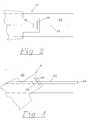
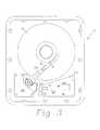
- FIG. 1is a view of a hard disk showing the read/write head in a first position.
- FIG. 2is a close up view of the hard disk showing a zero read/write offset at the first position.
- FIG. 3is a view of the hard disk of FIG. 1 showing the read/write head located at a second position.
- FIG. 4is a close up view of the hard disk showing the read/write offset at the second position.
- FIG. 5is diagram showing the servo fields of a track of a hard disk.
- FIG. 6is a block diagram of the circuitry of the hard disk.
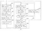
- FIG. 7is a flowchart of method according to an embodiment of the present invention.
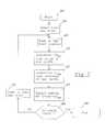
- FIG. 8is a flowchart of a part of the method of FIG. 7 .
- FIG. 9is a flow chart of another part of the method of FIG. 7 .
- FIG. 1is a plan view of a disk drive 2 with the cover removed.
- the hard disk driveincludes a magnetic platter 4 which comprises a rotatable storage disk operatively rotated at 120 Hz by a spindle motor (not shown). Data is written to and read from concentric tracks on each magnetic platter by read/write head 6 .
- Circuit board 13contains signal processing and control circuitry as will be explained later with reference to FIG. 6 .
- disk drive 2has only a single platter and only one read/write head.
- Multi-stage hard disks having several platters and read/write headsare also well known however and the present invention also finds application with them.
- Read/write head 6is supported by a slider 8 which glides over the surface of platter 4 .
- Slider 8is coupled to an actuator arm 10 which rotates about pivot assembly 12 .
- the actuator armis biased about the pivot by spring 14 against the action of a voice coil motor located beneath plate 16 .
- the concentric tracks on platter 4include a plurality of sectors having servo bits accurately located relative to the centerline of the track.
- FIG. 5depicts a servo bit sequence consisting of an AGC data field 26 , which may be used to set read sensitivity, an address mark signal 28 , a grey code 30 identifying the track number and a position error signal (PES) 32 consisting of four position bursts.
- the position burststypically consist of one or more cycles of continuous carrier spanning the track to be followed and adjacent tracks on either side.
- the signal processing to which the servo readback signal is subjectedincludes demodulation and decoding of the servo information and also includes the application of automatic gain control (AGC) to the signal read back from the disk's surface.
- AGCautomatic gain control
- AGCis applied to ensure that the readback signal strength is of relatively constant amplitude regardless of where the read/write head is relative to the track centerline or relative to the surface of the disk.
- the signal processing circuitry of the disk position control systemimplements a variable gain function either digitally or with analog circuitry. When the read/write head is over the AGC data field the gain of the recovered signal is adjusted to provide a predetermined constant amplitude signal in order to reduce demodulation errors. For example, when the AGC data field that is detected is of low amplitude then a relatively large amount of AGC is applied whereas when the detected AGC data field is of large amplitude a small degree of AGC is applied.
- the circuitryincludes a preamplifier 36 which is coupled to a read/write channel circuit 40 .
- the read/write channel circuitcontains AGC circuitry for normalizing the output from pre-amp 36 .
- Read/write channel circuit 40also includes demodulator circuitry for converting the analog signal from the read/write head 8 into a digital signal suitable for processing by microprocessor 46 .
- Channel circuit 40also includes logic circuits for detecting bit errors when reading data from tracks on platter 4 . Data segments of each track are typically encoded according to an error correcting code (ECC).
- ECCerror correcting code
- Microprocessor 46is programmed to determine the read/write head offset and to generate a look up table, stored in memory device 54 , recording the read/write head offset for each track. Instructions for the program that is executed by the microprocessor may be stored in a processor readable medium such as a memory chip coupled.
- the microprocessorcontrols a positioning driver 44 which provides positioning currents to voice coil motor 17 .
- spindle driver 52microprocessor 46 also controls spindle motor 50 which is rotatably coupled to platter 4 .
- An interface controller module 48is provided to facilitate data communications between the hard disk and external computational devices such as a host computer.
- Read/write channel circuit 40is also coupled to write amplifier 38 .
- the write amplifieris configured to drive the write portion of read/write head 8 in order to convert data signals into magnetic dipoles on the surface of the platter.
- a first methodis the “AGC scheme”.
- AGC schemea profile of the signal strength of the read back AGC data field ( FIG. 3 ) is obtained by micro-jogging the head from an initial point being a position, that is ⁇ 50% of the track's width from the track centerline, to a final point being a position, that is +50% of the track's width from the track centerline, and sensing the signal strengths of the recovered AGC data field at numerous intermediate test positions. For each test point, the amount of AGC that must be applied to normalize the amplitude of the recovered AGC data field signal is determined.
- test point at which a minimum of AGC was applied to normalize the signalindicates the point where the readback signal was strongest. Accordingly that point is written to memory as being the optimal MR offset for the particular track.
- the offsetis subsequently retrieved from memory and used in a servo routine to center the MR head during subsequent read operations. The procedure is repeated for every track.
- the AGC schemecan be made to operate very quickly if only one track sector is used to determine the MR offset.
- a disadvantage of determining the offset so rapidlyis that the final value registered in the AGC register only reflects the signal amplitude of the last sector read.
- the MR offset value that is determined to be optimalwill not be suitable for the track. This problem becomes more and more apparent when applied to disks with high track densities.
- a second method for determining MR offsetis the channel error rate (CER) scheme.
- the CER schemeuses the channel error rate function of the channel chip to monitor the bit error rate during the read operation for the read head positioned at a range of points across the track in question.
- the MR offsetis determined by writing a predetermined pattern of bits on the track centerline and then, upon incrementally moving the read head across the track from one test point to another, noting the point at which the number of bit errors is a minimum when reading back from the track.
- the CER schemeIn order for the CER scheme to be accurate it has been found that at least 1 ⁇ 10 6 bits must be read at every MR offset test point.
- the time taken to determine the optimal MR offset using the CER schemewould be unduly long.
- the CER schemeis considerably more reliable than the AGC scheme as it relies on actual error determinations to find the optimal MR offset point.
- FIG. 7is a high level flow chart of a method according to the preferred embodiment.
- the method of FIG. 7is implemented by means of a routine stored in the hard drive's program memory and executed by the hard drive's microprocessor.
- the routinemay be stored remotely and loaded to the microprocessor via the hard drive's interface controller circuit.
- the microprocessorprepares to execute the routine by making any initializations that may be required, such as initializing variables and allocating memory.
- an initial test trackis selected.
- the microprocessorlooks up the corresponding actuator position corresponding to the test track from memory and, at step 59 , generates commands to pivot the actuator to the appropriate position.
- the read write offset at the test track locationis determined by using an AGC test scheme. Details of the implementation of the AGC test scheme will be described shortly in relation to FIG. 8 .
- the AGC test schemeis applied over a range of 128 offset test points centered on the test track. As previously mentioned, the 128 test points span a distance equivalent to the spacing across six adjacent tracks. The offset test point at which the strongest AGC signal is received is recorded as OD AGC .
- a CER schemeis used to determine the optimal offset point OD CER over a sub-range of offset test points centered on OD AGC .
- the sub rangemay be (OD AGC ⁇ P) to (OD AGC +P) where P is say 8 so that the sub-range spans 17 points being approximately 1 ⁇ 8 th the width of the original 128 point range.
- the OD AGC valuewas determined over 128 offset points using the relatively fast AGC scheme the slower CER scheme is applied over only one eighth the number of offset test points. Accordingly, the AGC scheme is used to quickly narrow down to a subrange of test points in which an optimal test point is likely to lie. The CER strategy is then used to locate the optimal test point in the subrange.
- step 64the value of the optimal offset point for the test track is recorded in memory.
- step 66the microprocessor decides if all the tracks that are to be tested have been processed. If they have then the routine terminates at step 68 . If tracks remain to be processed then control diverts to step 70 where the actuator is controlled to seek to a new test track for subsequent processing in steps 59 to 64 as previously described.
- FIG. 8Details of the AGC scheme processing that occurs in step 60 of FIG. 7 are shown in FIG. 8 .
- the microprocessorcommands the read write channel and VCM controller to perform a DC erase operation on tracks near to the test track.
- a test patternis written on the centerline of the test track.
- the test patternincludes signal strength test data in the form of AGC data fields being signals of the type that are used to calibrate the read head's sensitivity in normal operation.
- the microprocessorcontrols the actuator to move the read element to the first offset point in the test range centered about the test track centerline.
- a read operationis performed and the magnitude of the AGC that must be applied to normalize the detected AGC data field signal is saved in memory in a data array structure at step 80 .
- the stored AGC magnitudesindicate the read signal strengths at each of the range of test points.
- the microprocessorchecks to see if all the offset points have been processed. In the event tat they have not then control diverts to step 88 where the actuator arm is controlled to seek the next point to be processed.
- a searchis performed of the data ray to find the test point OD AGC having the smallest applied AGC signal and hence to the test point where the strongest AGC data field signal was recovered by the read head.
- the variable OD AGCcomprises a first read position which is subsequently used to find a second read position from which the read-to-write offset is determined.
- the present inventionsets the located test point to OD AGC and saves that to memory.
- step 90a sub-range of offset test points (OD AGC ⁇ P) to (OD AGC +P) is calculated.
- the subrangeis centered on the first read position OD AGC however it could merely include the first read position rather than be centered on it.
- the microprocessorsends various commands to the read/write channel circuitry to set it into a mode for bit error rate monitoring.
- a DC erase of tracks neighboring the test trackis performed and a wedge write of a data pattern is made onto the test track.
- the CER schemeis time consuming to implement in that writing, reading and checking the bit pattern for each test point in order to obtain the bit error rate is relatively lengthy.
- the time taken to perform the CER schememay be significantly reduced by introducing wedge write and wedge read operations (at steps 96 and 100 ) in place of normal write and read operations.
- the wedge write operationdoes not have error correction coded (ECC) bytes written together with the data. Without the ECC bytes the wedge read operation can read enough sectors worth of bytes in one revolution of the disk for the channel error rate to be accurately determined.
- ECCerror correction coded
- the actuator armis controlled to move the head to the first offset test point of the subrange.
- the test patternis then read using a wedge read operation at step 100 .
- the error rate corresponding to the test point being processedis saved in a data array. The process is repeated via steps 104 and 110 until all of the offset test points have been processed.
- the memoryis searched to find the test point having the lowest error rate. That test point is taken to be the optimal MR offset for the track in question and is saved, either in a servo sector of the track or in memory.
- the MR offsetis set to the located test point and saved.
- the present inventionprovides a method for determining read/write head offset that is both relatively fast and accurate when compared to the methods hitherto available.
Landscapes
- Engineering & Computer Science (AREA)
- Signal Processing (AREA)
- Digital Magnetic Recording (AREA)
- Moving Of The Head To Find And Align With The Track (AREA)
Abstract
Description
Claims (19)
Priority Applications (1)
| Application Number | Priority Date | Filing Date | Title |
|---|---|---|---|
| US10/016,341US6839193B2 (en) | 2001-08-06 | 2001-12-11 | Method and apparatus for determining read-to-write head offset of a disk drive |
Applications Claiming Priority (2)
| Application Number | Priority Date | Filing Date | Title |
|---|---|---|---|
| US31036901P | 2001-08-06 | 2001-08-06 | |
| US10/016,341US6839193B2 (en) | 2001-08-06 | 2001-12-11 | Method and apparatus for determining read-to-write head offset of a disk drive |
Publications (2)
| Publication Number | Publication Date |
|---|---|
| US20030026017A1 US20030026017A1 (en) | 2003-02-06 |
| US6839193B2true US6839193B2 (en) | 2005-01-04 |
Family
ID=33476502
Family Applications (1)
| Application Number | Title | Priority Date | Filing Date |
|---|---|---|---|
| US10/016,341Expired - Fee RelatedUS6839193B2 (en) | 2001-08-06 | 2001-12-11 | Method and apparatus for determining read-to-write head offset of a disk drive |
Country Status (2)
| Country | Link |
|---|---|
| US (1) | US6839193B2 (en) |
| SG (1) | SG105521A1 (en) |
Cited By (4)
| Publication number | Priority date | Publication date | Assignee | Title |
|---|---|---|---|---|
| US20030202268A1 (en)* | 2002-04-26 | 2003-10-30 | Seagate Technology Llc | System and method for performing adaptive read retry operations in a data storage device |
| US20050270675A1 (en)* | 2004-06-08 | 2005-12-08 | Fujitsu Limited | Method of evaluating positioning accuracy of a magnetic head tester |
| US20080198492A1 (en)* | 2007-02-16 | 2008-08-21 | Samsung Electronics Co., Ltd. | Hard disk drive and associated method for optimizing write parameters |
| US8922923B2 (en) | 2011-03-01 | 2014-12-30 | Seagate Technology Llc | Interleaved automatic gain control for asymmetric data signals |
Families Citing this family (17)
| Publication number | Priority date | Publication date | Assignee | Title |
|---|---|---|---|---|
| JP3759711B2 (en)* | 2001-11-09 | 2006-03-29 | 富士通株式会社 | Magnetic disk system |
| US6943981B2 (en) | 2002-12-27 | 2005-09-13 | Matsushita Electric Co., Ltd. | Methods for improving servo-demodulation robustness |
| US7006315B2 (en)* | 2002-12-27 | 2006-02-28 | Matsushita Electric Industrial Co., Ltd. | Systems for improving servo-demodulation robustness |
| US7006311B2 (en)* | 2002-12-27 | 2006-02-28 | Matsushita Electric Industrial Co., Ltd | Systems for preventing channel control values from being corrupted to thereby improve servo-demodulation robustness |
| US7006312B2 (en) | 2002-12-27 | 2006-02-28 | Matsushita Electic Industrial Co., Ltd. | Methods for preventing channel control values from being corrupted to thereby improve servo-demodulation robustness |
| US7016133B2 (en)* | 2002-12-27 | 2006-03-21 | Matsushita Electric Industrial Co., Ltd. | Systems for detecting multiple occurrences of a SAM pattern to thereby improve servo-demodulation robustness |
| US6995935B2 (en) | 2002-12-27 | 2006-02-07 | Matsushita Electric Industrial Co., Ltd. | Methods for detecting multiple occurrences of a SAM pattern to thereby improve servo-demodulation robustness |
| US7092177B2 (en) | 2003-07-16 | 2006-08-15 | Matsushita Electric Industrial Co., Ltd. | Methods for searching for SAM patterns using multiple sets of servo demodulation detection parameters |
| US7072128B2 (en)* | 2003-07-16 | 2006-07-04 | Matsushita Electric Industrial Co., Ltd. | Methods for searching for SAM patterns at multiple nominal frequencies |
| US7075742B2 (en) | 2003-07-16 | 2006-07-11 | Matsushita Electric Industrial Co., Ltd. | Servo demodulator systems including multiple servo demodulators |
| US7054083B2 (en) | 2003-07-16 | 2006-05-30 | Matsushita Electric Industrial Co., Ltd. | Systems for searching for SAM patterns at multiple nominal frequencies |
| US6992856B2 (en)* | 2003-09-18 | 2006-01-31 | Matsushita Electric Industrial Co., Ltd. | Systems for limiting channel control values to thereby improve servo-demodulation robustness |
| US6992855B2 (en)* | 2003-09-18 | 2006-01-31 | Matsushita Electric Industrial Co., Ltd. | Methods for limiting channel control values to thereby improve servo-demodulation robustness |
| US20070279782A1 (en)* | 2006-05-31 | 2007-12-06 | Rydhan Abdul R | Method and apparatus for determining offset between read and write transducers in a disk drive |
| KR101832345B1 (en)* | 2011-06-30 | 2018-02-26 | 시게이트 테크놀로지 엘엘씨 | Method of tuning skew between read head and write head, and storage device thereof |
| US8773806B2 (en)* | 2012-02-08 | 2014-07-08 | Lsi Corporation | Disk-based storage device with head position control responsive to detected inter-track interference |
| US9361920B1 (en)* | 2015-02-19 | 2016-06-07 | Seagate Technology Llc | Compensation for track misalignment due to degradation of HAMR write head |
Citations (12)
| Publication number | Priority date | Publication date | Assignee | Title |
|---|---|---|---|---|
| US4982295A (en)* | 1988-01-28 | 1991-01-01 | Mitsumi Electric Co., Ltd. | Method for centering a read/write head of a magnetic data storage apparatus on a track of a magnetic disk |
| US5802584A (en) | 1995-09-01 | 1998-09-01 | Adaptec, Inc. | Hardware alignment in a headerless disk drive architecture |
| US5812755A (en) | 1995-09-01 | 1998-09-22 | Adaptec, Incorporated | Logical and physical zones for management of defects in a headerless disk drive architecture |
| US5812335A (en) | 1995-09-01 | 1998-09-22 | Adaptec, Inc. | Programmable data transfer without sector pulses in a headerless disk drive architecture |
| US5867353A (en)* | 1994-09-30 | 1999-02-02 | Maxtor Corporation | Off-track PES calibration for a magneto-resistive element |
| US5986847A (en)* | 1996-10-18 | 1999-11-16 | Samsung Electronics Co., Ltd. | Method and apparatus for providing read and write skew offset information for a magneto-resistive head |
| US6061201A (en)* | 1994-02-07 | 2000-05-09 | Seagate Technology, Inc. | Method of measuring the read-to-write offset in a disc drive having separate read and write elements |
| US6072650A (en) | 1997-09-29 | 2000-06-06 | Stmicroelectronics N.V. | Data placement variation compensation system |
| US6252731B1 (en) | 1997-10-16 | 2001-06-26 | Seagate Technology Llc | Parametric optimization using disc drive read channel quality measurements |
| US6275346B1 (en)* | 1998-02-21 | 2001-08-14 | Samsung Electronics Co., Ltd. | Technique of optimizing read/write channel parameters |
| US6476992B1 (en)* | 1999-07-08 | 2002-11-05 | Fujitsu Limited | Magnetic disk apparatus and optimum offset measuring method |
| US6631046B2 (en)* | 2000-01-10 | 2003-10-07 | Seagate Technology Llc | Servo track writing using extended copying with head offset |
Family Cites Families (2)
| Publication number | Priority date | Publication date | Assignee | Title |
|---|---|---|---|---|
| GB9312831D0 (en)* | 1993-06-22 | 1993-08-04 | Central Research Lab Ltd | Method and apparatus for the determination of azimuth error |
| US20030002190A1 (en)* | 2001-06-29 | 2003-01-02 | Teo Song Wee | Disk drive with optimized read gate delay |
- 2001
- 2001-12-11SGSG200107685Apatent/SG105521A1/enunknown
- 2001-12-11USUS10/016,341patent/US6839193B2/ennot_activeExpired - Fee Related
Patent Citations (12)
| Publication number | Priority date | Publication date | Assignee | Title |
|---|---|---|---|---|
| US4982295A (en)* | 1988-01-28 | 1991-01-01 | Mitsumi Electric Co., Ltd. | Method for centering a read/write head of a magnetic data storage apparatus on a track of a magnetic disk |
| US6061201A (en)* | 1994-02-07 | 2000-05-09 | Seagate Technology, Inc. | Method of measuring the read-to-write offset in a disc drive having separate read and write elements |
| US5867353A (en)* | 1994-09-30 | 1999-02-02 | Maxtor Corporation | Off-track PES calibration for a magneto-resistive element |
| US5802584A (en) | 1995-09-01 | 1998-09-01 | Adaptec, Inc. | Hardware alignment in a headerless disk drive architecture |
| US5812755A (en) | 1995-09-01 | 1998-09-22 | Adaptec, Incorporated | Logical and physical zones for management of defects in a headerless disk drive architecture |
| US5812335A (en) | 1995-09-01 | 1998-09-22 | Adaptec, Inc. | Programmable data transfer without sector pulses in a headerless disk drive architecture |
| US5986847A (en)* | 1996-10-18 | 1999-11-16 | Samsung Electronics Co., Ltd. | Method and apparatus for providing read and write skew offset information for a magneto-resistive head |
| US6072650A (en) | 1997-09-29 | 2000-06-06 | Stmicroelectronics N.V. | Data placement variation compensation system |
| US6252731B1 (en) | 1997-10-16 | 2001-06-26 | Seagate Technology Llc | Parametric optimization using disc drive read channel quality measurements |
| US6275346B1 (en)* | 1998-02-21 | 2001-08-14 | Samsung Electronics Co., Ltd. | Technique of optimizing read/write channel parameters |
| US6476992B1 (en)* | 1999-07-08 | 2002-11-05 | Fujitsu Limited | Magnetic disk apparatus and optimum offset measuring method |
| US6631046B2 (en)* | 2000-01-10 | 2003-10-07 | Seagate Technology Llc | Servo track writing using extended copying with head offset |
Cited By (7)
| Publication number | Priority date | Publication date | Assignee | Title |
|---|---|---|---|---|
| US20030202268A1 (en)* | 2002-04-26 | 2003-10-30 | Seagate Technology Llc | System and method for performing adaptive read retry operations in a data storage device |
| US7215494B2 (en)* | 2002-04-26 | 2007-05-08 | Seagate Technology Llc | System and method for performing adaptive read retry operations in a data storage device |
| US20050270675A1 (en)* | 2004-06-08 | 2005-12-08 | Fujitsu Limited | Method of evaluating positioning accuracy of a magnetic head tester |
| US7196861B2 (en)* | 2004-06-08 | 2007-03-27 | Fujitsu Limited | Method of evaluating positioning accuracy of a magnetic head tester |
| US20080198492A1 (en)* | 2007-02-16 | 2008-08-21 | Samsung Electronics Co., Ltd. | Hard disk drive and associated method for optimizing write parameters |
| US7880988B2 (en)* | 2007-02-16 | 2011-02-01 | Samsung Electronics Co., Ltd. | Hard disk drive and associated method for optimizing write parameters |
| US8922923B2 (en) | 2011-03-01 | 2014-12-30 | Seagate Technology Llc | Interleaved automatic gain control for asymmetric data signals |
Also Published As
| Publication number | Publication date |
|---|---|
| US20030026017A1 (en) | 2003-02-06 |
| SG105521A1 (en) | 2004-08-27 |
Similar Documents
| Publication | Publication Date | Title |
|---|---|---|
| US6839193B2 (en) | Method and apparatus for determining read-to-write head offset of a disk drive | |
| US6078453A (en) | Method and apparatus for optimizing the servo read channel of a hard disk drive | |
| US7035026B2 (en) | Method of manufacturing and disk drive produced by measuring the read and write widths and varying the track pitch in the servo-writer | |
| US6957379B1 (en) | Method and apparatus for selecting storage capacity of data storage media | |
| US6873488B2 (en) | Enhanced MR offset with dynamic tuning range | |
| US8014094B1 (en) | Disk drive expediting defect scan when quality metric exceeds a more stringent threshold | |
| US6754030B2 (en) | Optimal reader-to-writer offset measurement of a head in a disc drive for reduced track misregistration | |
| US6204660B1 (en) | Method of varying capacity of head disk drive during manufacturing process by checking head/disk combinations for defects | |
| KR100418740B1 (en) | Method for detecting abnormal magnetic head fly height, method for data writing and hard disk drive apparatus | |
| US6252731B1 (en) | Parametric optimization using disc drive read channel quality measurements | |
| US7158336B2 (en) | Window timing adjustment for spiral bursts | |
| US6078445A (en) | Gain control for a dual burst, dual frequency PES servo pattern | |
| EP1189222B1 (en) | Method and apparatus to detect and manage servo sectors with defects on servo pattern area in hard disk drives | |
| KR100468770B1 (en) | Retry method for copying with a offtrack error in HDD | |
| US7715140B2 (en) | Method of determining size of error and write control method for hard disc drive, hard disc drive using the write control method, and media storing computer programs for executing the methods | |
| US20030002190A1 (en) | Disk drive with optimized read gate delay | |
| US7173781B2 (en) | Multi-tracks MR offset tuning based on error count in certification process | |
| US7286319B2 (en) | Disk drive write control by servo gain | |
| US6335840B1 (en) | Thermal asperity pointer for servo sector | |
| KR100688506B1 (en) | Self-servo recording method, a suitable hard disk drive, and recording medium | |
| US7649705B2 (en) | Data read retry with read timing adjustment for eccentrity of disc in data storage device | |
| US7440211B2 (en) | Apparatus and/or method of controlling timing of servo pulses and disk drive using the method | |
| US8023379B2 (en) | Defect inspection method and disk drive using same | |
| KR20080006361A (en) | Method for defect management using change of defect scan factor and a hard disk drive using the method | |
| KR100734267B1 (en) | Measuring method of MR offset of hard disk drive and recording medium suitable for this |
Legal Events
| Date | Code | Title | Description |
|---|---|---|---|
| AS | Assignment | Owner name:SEAGATE TECHNOLOGY LLC, CALIFORNIA Free format text:ASSIGNMENT OF ASSIGNORS INTEREST;ASSIGNORS:CHONG, FONG KHEON;CHOO, QUEK LEONG;NGWE, MYINT;AND OTHERS;REEL/FRAME:012389/0587 Effective date:20011130 | |
| AS | Assignment | Owner name:JPMORGAN CHASE BANK, AS COLLATERAL AGENT, NEW YORK Free format text:SECURITY AGREEMENT;ASSIGNOR:SEAGATE TECHNOLOGY LLC;REEL/FRAME:013177/0001 Effective date:20020513 Owner name:JPMORGAN CHASE BANK, AS COLLATERAL AGENT,NEW YORK Free format text:SECURITY AGREEMENT;ASSIGNOR:SEAGATE TECHNOLOGY LLC;REEL/FRAME:013177/0001 Effective date:20020513 | |
| AS | Assignment | Owner name:SEAGATE TECHNOLOGY LLC, CALIFORNIA Free format text:ASSIGNMENT OF ASSIGNORS INTEREST;ASSIGNORS:TEO, SONGWEE;CHOO, QUEKLEONG;REEL/FRAME:013652/0025 Effective date:20021218 | |
| AS | Assignment | Owner name:SEAGATE TECHNOLOGY LLC, CALIFORNIA Free format text:RELEASE OF SECURITY INTERESTS IN PATENT RIGHTS;ASSIGNOR:JPMORGAN CHASE BANK, N.A. (FORMERLY KNOWN AS THE CHASE MANHATTAN BANK AND JPMORGAN CHASE BANK), AS ADMINISTRATIVE AGENT;REEL/FRAME:016967/0001 Effective date:20051130 | |
| FPAY | Fee payment | Year of fee payment:4 | |
| REMI | Maintenance fee reminder mailed | ||
| AS | Assignment | Owner name:WELLS FARGO BANK, NATIONAL ASSOCIATION, AS COLLATERAL AGENT AND SECOND PRIORITY REPRESENTATIVE, CALIFORNIA Free format text:SECURITY AGREEMENT;ASSIGNORS:MAXTOR CORPORATION;SEAGATE TECHNOLOGY LLC;SEAGATE TECHNOLOGY INTERNATIONAL;REEL/FRAME:022757/0017 Effective date:20090507 Owner name:JPMORGAN CHASE BANK, N.A., AS ADMINISTRATIVE AGENT AND FIRST PRIORITY REPRESENTATIVE, NEW YORK Free format text:SECURITY AGREEMENT;ASSIGNORS:MAXTOR CORPORATION;SEAGATE TECHNOLOGY LLC;SEAGATE TECHNOLOGY INTERNATIONAL;REEL/FRAME:022757/0017 Effective date:20090507 Owner name:JPMORGAN CHASE BANK, N.A., AS ADMINISTRATIVE AGENT Free format text:SECURITY AGREEMENT;ASSIGNORS:MAXTOR CORPORATION;SEAGATE TECHNOLOGY LLC;SEAGATE TECHNOLOGY INTERNATIONAL;REEL/FRAME:022757/0017 Effective date:20090507 Owner name:WELLS FARGO BANK, NATIONAL ASSOCIATION, AS COLLATE Free format text:SECURITY AGREEMENT;ASSIGNORS:MAXTOR CORPORATION;SEAGATE TECHNOLOGY LLC;SEAGATE TECHNOLOGY INTERNATIONAL;REEL/FRAME:022757/0017 Effective date:20090507 | |
| AS | Assignment | Owner name:MAXTOR CORPORATION, CALIFORNIA Free format text:RELEASE;ASSIGNOR:JPMORGAN CHASE BANK, N.A., AS ADMINISTRATIVE AGENT;REEL/FRAME:025662/0001 Effective date:20110114 Owner name:SEAGATE TECHNOLOGY HDD HOLDINGS, CALIFORNIA Free format text:RELEASE;ASSIGNOR:JPMORGAN CHASE BANK, N.A., AS ADMINISTRATIVE AGENT;REEL/FRAME:025662/0001 Effective date:20110114 Owner name:SEAGATE TECHNOLOGY INTERNATIONAL, CALIFORNIA Free format text:RELEASE;ASSIGNOR:JPMORGAN CHASE BANK, N.A., AS ADMINISTRATIVE AGENT;REEL/FRAME:025662/0001 Effective date:20110114 Owner name:SEAGATE TECHNOLOGY LLC, CALIFORNIA Free format text:RELEASE;ASSIGNOR:JPMORGAN CHASE BANK, N.A., AS ADMINISTRATIVE AGENT;REEL/FRAME:025662/0001 Effective date:20110114 | |
| AS | Assignment | Owner name:THE BANK OF NOVA SCOTIA, AS ADMINISTRATIVE AGENT, CANADA Free format text:SECURITY AGREEMENT;ASSIGNOR:SEAGATE TECHNOLOGY LLC;REEL/FRAME:026010/0350 Effective date:20110118 Owner name:THE BANK OF NOVA SCOTIA, AS ADMINISTRATIVE AGENT, Free format text:SECURITY AGREEMENT;ASSIGNOR:SEAGATE TECHNOLOGY LLC;REEL/FRAME:026010/0350 Effective date:20110118 | |
| FPAY | Fee payment | Year of fee payment:8 | |
| AS | Assignment | Owner name:SEAGATE TECHNOLOGY LLC, CALIFORNIA Free format text:TERMINATION AND RELEASE OF SECURITY INTEREST IN PATENT RIGHTS;ASSIGNOR:WELLS FARGO BANK, NATIONAL ASSOCIATION, AS COLLATERAL AGENT AND SECOND PRIORITY REPRESENTATIVE;REEL/FRAME:030833/0001 Effective date:20130312 Owner name:SEAGATE TECHNOLOGY INTERNATIONAL, CAYMAN ISLANDS Free format text:TERMINATION AND RELEASE OF SECURITY INTEREST IN PATENT RIGHTS;ASSIGNOR:WELLS FARGO BANK, NATIONAL ASSOCIATION, AS COLLATERAL AGENT AND SECOND PRIORITY REPRESENTATIVE;REEL/FRAME:030833/0001 Effective date:20130312 Owner name:SEAGATE TECHNOLOGY US HOLDINGS, INC., CALIFORNIA Free format text:TERMINATION AND RELEASE OF SECURITY INTEREST IN PATENT RIGHTS;ASSIGNOR:WELLS FARGO BANK, NATIONAL ASSOCIATION, AS COLLATERAL AGENT AND SECOND PRIORITY REPRESENTATIVE;REEL/FRAME:030833/0001 Effective date:20130312 Owner name:EVAULT INC. (F/K/A I365 INC.), CALIFORNIA Free format text:TERMINATION AND RELEASE OF SECURITY INTEREST IN PATENT RIGHTS;ASSIGNOR:WELLS FARGO BANK, NATIONAL ASSOCIATION, AS COLLATERAL AGENT AND SECOND PRIORITY REPRESENTATIVE;REEL/FRAME:030833/0001 Effective date:20130312 | |
| REMI | Maintenance fee reminder mailed | ||
| LAPS | Lapse for failure to pay maintenance fees | ||
| STCH | Information on status: patent discontinuation | Free format text:PATENT EXPIRED DUE TO NONPAYMENT OF MAINTENANCE FEES UNDER 37 CFR 1.362 | |
| FP | Lapsed due to failure to pay maintenance fee | Effective date:20170104 | |
| AS | Assignment | Owner name:SEAGATE TECHNOLOGY PUBLIC LIMITED COMPANY, CALIFORNIA Free format text:RELEASE BY SECURED PARTY;ASSIGNOR:THE BANK OF NOVA SCOTIA;REEL/FRAME:072193/0001 Effective date:20250303 Owner name:SEAGATE TECHNOLOGY, CALIFORNIA Free format text:RELEASE BY SECURED PARTY;ASSIGNOR:THE BANK OF NOVA SCOTIA;REEL/FRAME:072193/0001 Effective date:20250303 Owner name:SEAGATE TECHNOLOGY HDD HOLDINGS, CALIFORNIA Free format text:RELEASE BY SECURED PARTY;ASSIGNOR:THE BANK OF NOVA SCOTIA;REEL/FRAME:072193/0001 Effective date:20250303 Owner name:I365 INC., CALIFORNIA Free format text:RELEASE BY SECURED PARTY;ASSIGNOR:THE BANK OF NOVA SCOTIA;REEL/FRAME:072193/0001 Effective date:20250303 Owner name:SEAGATE TECHNOLOGY LLC, CALIFORNIA Free format text:RELEASE BY SECURED PARTY;ASSIGNOR:THE BANK OF NOVA SCOTIA;REEL/FRAME:072193/0001 Effective date:20250303 Owner name:SEAGATE TECHNOLOGY INTERNATIONAL, CAYMAN ISLANDS Free format text:RELEASE BY SECURED PARTY;ASSIGNOR:THE BANK OF NOVA SCOTIA;REEL/FRAME:072193/0001 Effective date:20250303 Owner name:SEAGATE HDD CAYMAN, CAYMAN ISLANDS Free format text:RELEASE BY SECURED PARTY;ASSIGNOR:THE BANK OF NOVA SCOTIA;REEL/FRAME:072193/0001 Effective date:20250303 Owner name:SEAGATE TECHNOLOGY (US) HOLDINGS, INC., CALIFORNIA Free format text:RELEASE BY SECURED PARTY;ASSIGNOR:THE BANK OF NOVA SCOTIA;REEL/FRAME:072193/0001 Effective date:20250303 |