US6838867B2 - Electrical-energy meter - Google Patents
Electrical-energy meterDownload PDFInfo
- Publication number
- US6838867B2 US6838867B2US10/185,678US18567802AUS6838867B2US 6838867 B2US6838867 B2US 6838867B2US 18567802 AUS18567802 AUS 18567802AUS 6838867 B2US6838867 B2US 6838867B2
- Authority
- US
- United States
- Prior art keywords
- electrical
- energy meter
- circuit board
- base
- board
- Prior art date
- Legal status (The legal status is an assumption and is not a legal conclusion. Google has not performed a legal analysis and makes no representation as to the accuracy of the status listed.)
- Expired - Lifetime
Links
- 239000004020conductorSubstances0.000claimsabstractdescription14
- 238000004891communicationMethods0.000claimsdescription15
- 239000012815thermoplastic materialSubstances0.000claimsdescription12
- 239000004973liquid crystal related substanceSubstances0.000claimsdescription10
- 230000001186cumulative effectEffects0.000claimsdescription6
- 238000005452bendingMethods0.000claimsdescription2
- 239000004033plasticSubstances0.000claimsdescription2
- 229920003023plasticPolymers0.000claimsdescription2
- 230000013011matingEffects0.000claims3
- 230000002401inhibitory effectEffects0.000claims2
- 230000003287optical effectEffects0.000claims1
- 238000013461designMethods0.000description7
- 238000004519manufacturing processMethods0.000description6
- 230000008901benefitEffects0.000description4
- 239000002184metalSubstances0.000description4
- 229920001470polyketonePolymers0.000description4
- 238000005476solderingMethods0.000description3
- 239000000725suspensionSubstances0.000description3
- 229920001187thermosetting polymerPolymers0.000description3
- 230000000881depressing effectEffects0.000description2
- 238000009826distributionMethods0.000description2
- 238000009434installationMethods0.000description2
- 239000000463materialSubstances0.000description2
- 230000000717retained effectEffects0.000description2
- 238000000926separation methodMethods0.000description2
- 230000000007visual effectEffects0.000description2
- 229910000906BronzeInorganic materials0.000description1
- 230000003466anti-cipated effectEffects0.000description1
- 230000004888barrier functionEffects0.000description1
- 239000010974bronzeSubstances0.000description1
- 238000004140cleaningMethods0.000description1
- 238000007796conventional methodMethods0.000description1
- KUNSUQLRTQLHQQ-UHFFFAOYSA-Ncopper tinChemical compound[Cu].[Sn]KUNSUQLRTQLHQQ-UHFFFAOYSA-N0.000description1
- 239000013078crystalSubstances0.000description1
- 230000000694effectsEffects0.000description1
- 238000010348incorporationMethods0.000description1
- 239000002917insecticideSubstances0.000description1
- 238000003780insertionMethods0.000description1
- 230000037431insertionEffects0.000description1
- 238000012423maintenanceMethods0.000description1
- 230000014759maintenance of locationEffects0.000description1
- 238000012986modificationMethods0.000description1
- 230000004048modificationEffects0.000description1
- 239000013307optical fiberSubstances0.000description1
- 230000008439repair processEffects0.000description1
- 230000000452restraining effectEffects0.000description1
- 239000000523sampleSubstances0.000description1
- 239000002904solventSubstances0.000description1
- 230000006641stabilisationEffects0.000description1
- 238000011105stabilizationMethods0.000description1
- 238000003860storageMethods0.000description1
- 239000013589supplementSubstances0.000description1
- 238000012360testing methodMethods0.000description1
Images


Classifications
- G—PHYSICS
- G01—MEASURING; TESTING
- G01R—MEASURING ELECTRIC VARIABLES; MEASURING MAGNETIC VARIABLES
- G01R22/00—Arrangements for measuring time integral of electric power or current, e.g. electricity meters
- G01R22/06—Arrangements for measuring time integral of electric power or current, e.g. electricity meters by electronic methods
- G01R22/061—Details of electronic electricity meters
- G01R22/065—Details of electronic electricity meters related to mechanical aspects
- G—PHYSICS
- G01—MEASURING; TESTING
- G01R—MEASURING ELECTRIC VARIABLES; MEASURING MAGNETIC VARIABLES
- G01R22/00—Arrangements for measuring time integral of electric power or current, e.g. electricity meters
Definitions
- the present inventionrelates to distribution systems for electrical power. More particularly, the invention relates to a solid-state meter for measuring the consumption of electrical energy in, for example, a residential dwelling.
- Solid-state electrical energy metersalso referred to as “watt-hour meters,” are used on a widespread basis in commercial and industrial applications. Solid-state meters offer advantages in relation to conventional electro-mechanical electrical-energy meters. For example, solid-state electrical-energy meters can incorporate features that offer programmability, as well as flexibility in tailoring the various functions of the meter to a particular user, without substantially increasing the overall cost of the meter.
- solid-state electrical-energy metersin residential applications has not progressed to the extent of commercial and industrial use.
- typical residential applicationsdo not require the comparatively high degree of functionality called for in many commercial and industrial applications.
- the cost advantages offered by solid-state meters in relation to programmability and functionality, in generalare not as significant in residential applications as they are in commercial and industrial applications.
- Conventional electrical-energy meters of both the electromechanical and solid-state typetypically incorporate a relatively large number of fasteners, e.g., screws, rivets, eyelets, pins, etc., to secure the various components thereof. These fasteners increase the overall parts count and the assembly time of the meter, and thus raise the manufacturing cost thereof.
- fastenerse.g., screws, rivets, eyelets, pins, etc.
- thermosetting plasticsare relatively hard and brittle, and thus are not well suited to withstand the impact loads that electrical-energy meters are typically exposed to during shipping and installation.
- components manufactured from these types of materialsmust have relatively large cross sections to provide the components with sufficient resistance to the anticipated impact loads. This requirement increases the manufacturing cost of the meter.
- the brittle quality of thermosetting plasticsprecludes the use of cost-effective design features that require resilient components.
- a presently-preferred embodiment of an electrical-energy metercomprises a base adapted to be mounted on a supporting surface, a current sensor assembly comprising a plurality of contact blades extending through the base and adapted to electrically contact a conductor of electrical energy, and a current transformer mechanically coupled to the base and electrically coupled to the contact blades.
- the current transformeris adapted to produce an electrical output proportional to an electrical current in the conductor of electrical energy.
- the electrical-energy meterfurther comprises a circuit board assembly comprising a main circuit board electrically coupled to the current transformer and the contact blades.
- the circuit board assemblyis adapted to calculate and display a cumulative amount of electrical energy passing through the conductor of electrical energy based on the electrical output of the current transformer and a voltage of the conductor of electrical energy.
- the electrical-energy meteralso comprises a circuit-board support member comprising a rim portion fixedly coupled to the base, and a first bracket adjoining the rim portion.
- the first brackethas a first and a second leg each extending away from the rim portion and the base and each being adapted to securely engage the main circuit board.
- an electrical-energy metercomprises a base, and a current sensor assembly comprising a plurality of contact blades and at least one current transformer mechanically coupled to the base and electrically coupled to the contact blades.
- the electrical-energy meterfurther comprises a circuit board assembly comprising a circuit board electrically coupled to the current transformer and the contact blades, and a circuit-board support member comprising a substantially circular rim portion having a first and a second plurality of retaining clips formed thereon.
- the first plurality of retaining clipsare each adapted to securely engage the base by way of a corresponding through hole formed in the base, whereby the circuit-board support member is secured to the base without the use of external fasteners.
- the electrical-energy meteralso comprises an inner housing adapted to securely engage the circuit-board support member so the that the inner housing and the base substantially enclose the current sensor assembly and the circuit board assembly.
- the inner housingcomprises a plurality of snaps each having a through hole formed therein.
- Each of the second plurality of retaining clipsis adapted to substantially align with and become disposed in a respective one of the through holes in the snaps as the inner housing is mated with the circuit-board support member thereby causing the second plurality of retaining clips to securely engage the inner housing whereby the inner housing is secured to the circuit-board support member without the use of external fasteners.
- FIG. 1is an exploded, top perspective view of a presently-preferred embodiment of an electrical-energy meter
- FIG. 2is a top perspective, partial cutaway view of the electrical-energy meter shown in FIG. 1 ;
- FIG. 3is a bottom perspective view of a base and a current sensor assembly of the electrical-energy meter shown in FIGS. 1 and 2 ;
- FIG. 4is a top perspective view of a current transformer of the current sensor assembly shown in FIG. 3 ;
- FIG. 5is a bottom perspective view of the base shown in FIG. 4 , a power-disconnect switch, and an alternative, two-transformer current sensor assembly of the electrical-energy meter shown in FIGS. 1 and 2 ;
- FIG. 6is a bottom perspective view of a circuit board assembly and a radio-communications antenna of the electrical-energy meter shown in FIGS. 1 and 2 ;
- FIG. 7is a side perspective view of a circuit-board support member and circuit boards of the electrical-energy meter shown in FIGS. 1 and 2 ;
- FIG. 8Ais a top perspective view of the circuit-board support member shown in FIG. 7 ;
- FIG. 8Bis a magnified view of the area designated “A” in FIG. 8A ;
- FIG. 8Cis a magnified view of the area designated “B” in FIG. 8A ;
- FIG. 9is a top perspective view of the circuit board assembly and the radio-communications antenna shown in FIG. 6 , and a lighted crystal display and a mounting bracket of the electrical-energy meter shown in FIGS. 1 and 2 ;
- FIG. 10is a side perspective view of the mounting bracket shown in FIG. 9 ;
- FIG. 11Ais a top view of the radio-communications antenna shown in FIGS. 6 and 9 , showing mounting tabs, a radio-frequency feed, and a ground feed of the antenna in their initial (flat) positions;
- FIG. 11Bis a top perspective view of the radio-communications antenna shown in FIGS. 6 , 9 , and 11 A, showing the mounting tabs in their deployed positions and the radio-frequency and ground feeds in their initial (flat) positions;
- FIG. 12is a bottom perspective view of the circuit board, the radio-communications antenna, the liquid crystal display, and the mounting bracket shown in FIGS. 6 , 9 , 10 , 11 A, or 11 B, with the mounting tabs and the radio-frequency and ground feeds of the radio-communications antenna in their deployed positions;
- FIG. 13Ais a top perspective view of the base shown in FIGS. 3 and 5 , and an inner housing and nameplate of the electrical-energy meter shown in FIGS. 1 and 2 ;
- FIG. 13Bis a magnified view of the area designated “C” in FIG. 13A ;
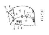
- FIG. 13Cis a top perspective, cutaway view of the inner housing shown in FIGS. 13A and 13B ;
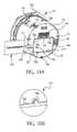
- FIG. 14Ais a side perspective view of the base and the inner housing in FIGS. 3 , 5 , 13 A, or 13 B, and a hanger of the electrical-energy meter shown in FIGS. 1 and 2 , with the hanger is a stored position;
- FIG. 14Bis a magnified view of the area designated “D” in FIG. 14A , with the hanger in a deployed position;
- FIG. 14Cis a side perspective view of the hanger shown in FIGS. 14A and 14B ;
- FIG. 15Ais a bottom perspective, exploded view of the base shown in FIGS. 3 , 5 , 13 , and 14 A, and the power-disconnect switch and the two-transformer current sensor assembly shown in FIG. 5 ;
- FIG. 15Bis a top perspective view of the base, the circuit-board support member, the power-disconnect switch, the two-transformer current sensor assembly, the liquid-crystal display, the mounting bracket, the circuit board assembly, and the radio-communications antenna shown in FIGS. 3 , 5 , 6 , 7 , 8 A, 8 B, 8 C, 9 , 10 , 11 A, 11 B, 12 , 13 A, 14 A, 14 B, or 15 A; and
- FIG. 16is a bottom perspective view of the base shown in FIGS. 3 , 5 , 13 , 14 A, 15 A, and 15 B.
- FIGS. 1 to 15 BA presently-preferred embodiment of a solid-state electrical-energy meter 10 adapted for residential use is depicted in FIGS. 1 to 15 B.
- the electrical-energy meter 10is described in detail for exemplary purposes only, as the various features of the present invention can be incorporated into other types of electrical-energy meters, including electrical-energy meters adapted for commercial and industrial uses.
- the electrical-energy meter 10comprises a base 12 , a circuit-board support member 14 , a current sensor assembly 15 , a circuit board assembly 16 , an inner housing 18 , and a cover 20 .
- the base 12is depicted in detail in FIGS. 3 , 5 , 14 A, and 16 .
- the base 12is preferably molded from a reinforced thermoplastic material having the requisite mechanical, electrical, and thermal properties, flammability rating, UV stabilization, and resistance to common solvents such as insecticides and cleaning solutions.
- a reinforced thermoplastic materialhaving the requisite mechanical, electrical, and thermal properties, flammability rating, UV stabilization, and resistance to common solvents such as insecticides and cleaning solutions.
- An example of such thermoplastic materialis polyketone or PBT.
- the current sensor and conductor assembly 15is mounted on the base 12 (see FIG. 3 ). More particularly, the base 12 has a tongue-shaped support 24 formed thereon. The support 24 is tapered so that the width and thickness thereof increase progressively from the top (freestanding) to the bottom ends thereof.
- the current sensor 15comprises an annular current transformer 26 having resilient crush ribs 28 positioned along an inner circumference thereof (see FIG. 4 ).
- the current transformer 26is securely positioned around the support 24 . More specifically, the crush ribs 28 interferedly contact the support 24 as the current transformer 26 is pushed onto the support 24 . Contact between the crush ribs 28 and the support 24 causes the crush ribs 28 to deform and securely engage the support 28 , thereby securing the current transformer 26 (and the current sensor and conductor assembly 15 ) to the base 12 .
- Alternative configurations of the electrical-energy meter 10may include two of the current transformers 28 , as depicted in FIGS. 5 , 15 A, and 15 B.
- the base 12can accommodate the two-transformer configuration with no modifications thereto, as follows.
- the base 12has four receptacles 29 formed therein (see FIG. 16 ).
- the current transformers 28each have a first pair of tabs 30 formed on one side thereof, and a second pair of tabs 31 formed on an opposing side thereof (see FIG. 4 ).
- the receptacles 29are each adapted to securely engage a corresponding one of the tabs 30 .
- the circuit-board support member 14is adapted to securely engage the tabs 31 by way of a groove 51 formed in the circuit-board support member 14 (as described below), thereby securing the current transformers 28 in place between the circuit-board support member 14 and the base 1 .
- the circuit board assembly 16comprises a main circuit board 38 and a substantially flat liquid crystal display (LCD) 40 (see FIG. 9 ).
- the main circuit board 38is electrically coupled to the current transformer(s) 28 .
- the main circuit board 38also receives an input or line voltage, i.e., a voltage corresponding to the voltage in the electrical-energy line to which the electrical-energy meter 10 is connected, by way of a first and a second voltage spring 42 , 43 (described in detail below).
- the circuit board assembly 16is adapted to calculate the total (cumulative) watt-hours of power that have passed through the electrical-energy meter 10 over time based on the current and voltage input, using conventional techniques and components known to those skilled in the field of electrical-energy meter design.
- the circuit board assembly 16continually updates the cumulative watt-hours, and displays the updated value on the LCD 40 .
- the electrical-energy meter 10can accommodate one or more optional circuit boards 74 a , 74 b , 74 c adapted to perform additional functions such as communications, pulse/relay output, service disconnect and installation, etc. (see FIG. 6 ).
- the ability to incorporate multiple circuit boardscan enhance the functionality of the electrical-power meter 10 , and thus represents a substantial advantage over conventional meter designs, which typically incorporate those functions into a single, main circuit board.
- Specific details relating to the optional circuit boards 74 a , 74 b , 74 c , and further details relating to the circuit board assembly 16are not necessary to an understanding of the invention, and therefore are not presented herein.
- the circuit-board support member 14partially supports the circuit board assembly 16 and the optional circuit boards 74 a , 74 b , 74 c , as follows.
- the circuit-board support member 14comprises a ring-shaped portion 14 a , and a bracket 14 b unitarily formed with and extending from the rim portion 14 a (see FIGS. 7 and 8 A).
- the bracket 14 bcomprises substantially L-shaped side portions 14 c , 14 d .
- the side portions 14 c , 14 deach have a groove 46 formed therein.
- the grooves 46are adapted to securely engage opposing side edges of the 30 main circuit board 38 , thereby securing the circuit board assembly 16 to the circuit-board support member 14 (and the base 12 ) (see FIG. 7 ).
- the bracket 14 balso includes a transverse portion 14 f unitarily formed with the side portions 14 c , 14 d .
- the substantially L-shaped configuration of the side portions 14 c , 14 dpositions the transverse portion 14 f at an elevation above that of the side portions 14 c , 14 d (from the perspective of FIGS. 7 and 8 A).
- the transverse portion 14 fhas a groove 47 formed in a rearward-facing surface thereon. The groove 47 securely engages a forward edge of the optional circuit board 74 b.
- a second bracket 14 gis unitarily formed with and extends from the rim portion 14 a .
- the second bracket 14 ghas a transverse portion 14 h .
- the transverse portion 14 hhas a groove 49 formed in a forward-facing surface thereof. The groove 49 securely engages a rearward edge of the optional circuit board 74 b .
- the optional circuit board 74 bis thus supported by the brackets 14 b , 14 g.
- the transverse portion 14 hhas a groove 51 formed in a rearward-facing surface thereof.
- the groove 51is adapted to securely receive the tabs 31 on the current transformers 28 , thereby securing the current transformers 28 to the circuit-board support member 14 when the electrical-energy meter 10 is configured with two of the current transformers 28 (see FIG. 5 ).
- the bracket 14 gis positioned at an elevation above that of the bracket 14 b , from the perspective of FIGS. 7 and 8A (thereby giving the optional circuit board 74 b an angled orientation as depicted in FIG. 7 ).
- This featurepermits the circuit-board support member 14 to be molded using relatively simple and inexpensive “straight-pull” tooling (as opposed to a slicing apparatus), with no effect on the overall functionality of the circuit-board support member 14 . Forming the circuit-board support member 14 using straight-pull tooling simplifies the manufacturing process, and reduces the manufacturing cost of the circuit-board support member 14 .
- the circuit-board support member 14includes two board supports 71 unitarily formed with the rim portion 14 a (see FIGS. 7 and 8 A).
- the board supports 71each have a groove 73 formed therein.
- the grooves 73are adapted to securely engage opposing sides of the optional circuit board 74 a , thereby causing the board supports 71 to partially support the optional circuit board 74 a .
- the circuit-board support member 14likewise includes two circuit-board support fingers 75 unitarily formed with the rim portion 14 a .
- the circuit-board support fingers 75each have a groove 77 formed therein.
- the grooves 77are adapted to securely engage opposing sides of the optional circuit board 74 c , thereby causing the circuit-board support fingers 75 to partially support the optional circuit board 74 c.
- the circuit-board support member 14is secured to the base 12 as follows.
- the circuit-board support member 14has a total of eight retaining clips 81 formed thereon.
- Each retaining clip 81has a barbed portion 81 a (see FIG. 8 C).
- the base 12includes a rim portion 12 c having a total of eight through holes 90 formed therein (see FIGS. 2 and 8 C).
- the circuit-board support member 14 and the base 12are mated by substantially aligning each retaining clip 81 with a corresponding snap 76 , and urging the circuit-board support member 14 toward the base 12 by applying moderate force to the circuit-board support member 14 .
- each retaining clip 81The barb-shaped portions 81 a of each retaining clip 81 are adapted to contact the rim portion 12 c and resiliently deform as the circuit-board support member 14 is moved toward the base 12 . Continued movement of the circuit-board support member 14 toward the base 12 causes each barb-shaped portion 81 a to substantially align with a corresponding one of the through holes 90 . The resilience of the barb-shaped portion 81 a causes the barb-shaped portion 81 a to snap into the through hole 82 and thereby engage the rim portion 12 c.
- the engagement of the barb-shaped portions 81 a and the rim portion 12 cretains the circuit-board support member 14 on the base 12 .
- the circuit-board support member 14can be quickly and easily secured to the base 12 without the use of external fasteners.
- the circuit-board support member 14can be released from the base 12 by depressing the barb-shaped portions 81 a to move each barb-shaped portion 81 a out of the corresponding through hole 90 .
- the retaining clips 81provide a secure connection that minimizes the potential for accidental separation of the circuit-board support member 14 from the base 12 .
- circuit-board support member 14Further details relating to the circuit-board support member 14 are presented below.
- the current sensor assembly 15comprises the current transformer 26 and the voltage springs 42 , 43 , as noted previously.
- the current sensor assembly 15also comprises a pair of input leads 48 , a corresponding pair of output leads 50 , a first pair of contact blades 52 a , and a substantially identical second pair of contact blades 52 b .
- the contact blades 52 aare each electrically and mechanically coupled to a respective one of the input leads 48
- the contact blades 52 bare each electrically and mechanically coupled to a respective one of the output leads 50 .
- the contact blades 52 a , 52 bcomply with ANSI specifications for residential electrical-energy meters. Each contact blade 52 a , 52 b extends through the base 12 by way of a corresponding slot 54 formed in the base 12 (see FIGS. 3 , 14 A, and 16 ). The blades 52 a , 52 b may be retained in the slots 54 by conventional means such as cotter pins or, preferably, by the structure described in U.S. Pat. No. 5,966,010, which is incorporated by reference herein its entirety. (The contact blades 52 a , 52 b are also secured by the circuit-board support member 14 , as explained in detail below.)
- Each contact blade 52 a , 52 bprojects from the rear surface 12 a of the base 12 proximate a corresponding voltage shield 22 that extends from the rear surface 12 (see FIG. 14 A).
- the contact blades 52 a , 52 bare each adapted to slidably and securely engage a corresponding ANSI-standard socket mounted on the residential dwelling and electrically coupled to the line that supplies electrical power to the dwelling. More particularly, the ANSI-standard sockets each comprise spring-loaded jaws that securely grasp the corresponding contact blade 52 a , 52 b.
- the input leads 48electrically couple the power line of the residential dwelling to the input side of the current transformer 26 .
- the current transformer 26generates a low-voltage output that is proportional to the current entering the current transformer 26 by way of the input leads 48 .
- the output leads 50electrically couple the output side of the current transformer 26 to the power line of the residential dwelling.
- the low-voltage output of the current transformer 26is processed by the circuit board assembly 16 to generate a display that represents the cumulative watt-hours of power consumed by the residential dwelling over time. (Further details relating to the current transformer 26 are not necessary to an understanding of the invention, and therefore are not presented herein.)
- the input and output leads 48 , 50are not insulated. Compliance with the applicable ANSI standards for surge-voltage capability is achieved by spacing the input and output leads 48 , 50 as shown in the figures, and through the use of the support 24 . More specifically, the support 24 is positioned between the input leads 48 where the input leads 48 come into proximity, i.e., where the input leads 48 are coupled to the current transformer 26 (see FIG. 3 ). The support 24 is likewise positioned between the output leads 50 where the output leads 50 come into close proximity, i.e., where the output leads 48 are coupled to the current transformer 26 .
- the insulative properties of the thermoplastic material from which the support 24 is formedcause the support 24 to act as a voltage barrier between the input leads 48 , and between the output leads 50 .
- the support 24thereby prevents or inhibits surge voltages from passing between the input leads 48 , and between the output leads 50 . (It should be noted that the support 24 performs the noted voltage-blocking function in configurations that use a single current transformer 26 only.)
- the contact blades 52 a , 52 bare also secured by the circuit-board support member 14 , as noted above.
- the circuit-board support member 14includes four keys 94 unitarily formed with the rim portion 14 a (see FIGS. 7 and 8 A). Each of the keys 94 substantially aligns with and is partially disposed in a respective slot 54 in the base 12 when the circuit-board support member 14 and the base 12 are coupled as noted above. The resulting contact between the key 94 and the corresponding contact blade 52 a , 52 inhibits the contact blade 52 a , 52 from backing out of the corresponding slot 54 .
- the keys 94 and the slots 54thus permit the contact blades 52 a , 52 b to be installed in, secured to, and removed from the base 12 quickly and easily, without the use of external fasteners, locking pins, or tooling.
- the first and second voltage springs 42 , 43are as follows.
- the first and second voltage springs 42 , 43are formed from an electrically-conductive material, and are not insulated.
- the voltage springs 42 , 43electrically couple the contact blades 52 a to the main circuit board 38 (see FIG. 6 ).
- the voltage springs 42 , 43thus provide the main circuit board 38 with signals corresponding to the line voltage being input to the electrical-energy meter 10 .
- a first end 42 a the voltage spring 42is adapted to grasp opposing sides of one of the contact blades 52 a , as depicted in FIG. 6.
- a first end 43 a the voltage spring 43is likewise adapted to grasp opposing sides of the other of the contact blades 52 a . (The voltage springs 42 , 43 are not soldered or otherwise hard-wired to the contact blades 52 a ).
- This arrangementpermits the contact blades 52 a to flex to a limited degree while remaining in contact with the voltage springs 42 , 43 , and without placing substantial stress on the voltage springs 42 , 43 (flexing of the contact blades 52 a , 52 b normally occurs when the contact blades 52 a , 52 b are inserted into the corresponding mounting sockets on the residential dwelling).
- the ends 42 a , 42 beach include a portion that is spaced apart from the corresponding contact blade 52 a , 52 b , thereby facilitating a voltage connection between the contact blade 52 a , 52 b and an auxiliary circuit board.
- the first voltage spring 42comprises a voltage disconnect 58 , as required by applicable ANSI specifications (see FIG. 6 ).
- a second end 42 b of the voltage spring 42 , and a second end 43 b of the voltage spring 43are electrically and mechanically coupled to the main circuit board 38 as follows.
- the main circuit board 38comprises a first and a second contact pad 55 a , 55 b .
- the first and second contact pads 54 a , 54 bare positioned respectively on top and bottom surfaces of the main circuit board 38 , proximate an edge of the main circuit board 38 .
- the second end 42 b of the voltage spring 42is secured to first contact pad 55 a by conventional means such as soldering.
- the second end 43 b of the voltage spring 43is likewise secured to the second contact pad 55 b by conventional means such as soldering. This arrangement forms a “card-edge” connection between the voltage springs 42 , 43 and the main circuit board 38 .
- the voltage springs 42 , 43are coupled to opposing sides of the main circuit board 38 .
- This featureenhances the surge-voltage capability of the main circuit board 38 . More particularly, a given level of surge-voltage capability can be achieved with a smaller overall spacing between the contact pads 55 a , 55 b if the contact pads 55 a , 55 b are positioned on opposite surfaces of the main circuit board 38 . Closer spacing between the contact pads 55 a , 55 b conserves space on the main circuit board 38 . This feature is particularly advantageous given the limited amount of space available within the electrical-energy meter 10 for the main circuit board 38 .
- the LCD 40is mounted on the main circuit board 38 using a support bracket 60 (see FIGS. 9 and 10 ).
- the support bracket 60secures the LCD 40 in a substantially perpendicular orientation in relation to the main circuit board 38 .
- the support bracket 60thus permits the main circuit board 38 to be positioned in a substantially horizontal orientation; this feature can facilitate a more compact overall configuration for the electrical-energy meter 10 in comparison to conventional mounting arrangements in which the LCD is positioned substantially parallel to a corresponding circuit board.
- the support bracket 60is preferably molded from a reinforced thermoplastic material such as polyketone or PBT.
- the support bracket 60includes a first and a second support arm 60 a , 60 b , and a first and a second mounting foot 60 c , 60 d adjoining the respective first and second support arms 60 a , 60 b .
- the support bracket 60also includes a transverse member 60 e having molded springs 60 f formed thereon.
- the LCD 40is supported by the mounting feet 60 c , 60 d . More particularly, the springs 60 f bias the LCD 40 downward, into the mounting feet 60 c , 60 d , thereby restraining the LCD 40 vertically.
- the LCD 40is restrained horizontally by the support arms 60 a , 60 b , and by a backing plate 60 g that adjoins the support arms 60 a , 60 b.
- the support bracket 60further comprises a first and a second forward mount 60 h , 60 i , and a third and a fourth mounting arm 60 j , 60 k .
- the third and fourth mounting arms 60 j , 60 kadjoin the respective first and second forward mounts 60 h , 60 i , and extend substantially perpendicularly to the first and second support arms 60 a , 60 b .
- the support bracket 60also comprises a first and a second rearward mount 60 l , 60 m.
- the forward mounts 60 h , 60 ieach have a groove formed therein and adapted to securely receive an edge of the main circuit board 38 , as depicted in FIG. 9 .
- the rearward mounts 60 l , 60 meach have a notch formed therein, and are adapted to snap into a respective slot formed in the main circuit board 38 . More particularly, the rearward mounts 60 l , 60 m are adapted to resiliently deform as the rearward mounts 60 l , 60 m are urged into the respective slots.
- the rearward mounts 60 l , 60 mare adapted to securely engage the main circuit board 38 by way of the notches once the rearward mounts 60 l , 60 m have been inserted into the slots.
- the configuration of the support bracket 60permits the LCD 40 to be mounted on the main circuit board 38 without the use of any external fasteners. More particularly, the LCD 40 is mounted by snapping the LCD 40 into the support bracket 60 , inserting leads 40 a of the LCD 40 into corresponding through holes formed in the main circuit board 38 , and mounting the support bracket 60 on the main circuit board 38 by way of the mounts 60 h , 60 i , 60 l , 60 m . The leads 40 a of the LCD 40 (and the other component leads mounted on the main circuit board 38 ) are subsequently wave-soldered to the main circuit board 38 .
- the LCD 40is specially configured to accommodate the perpendicular mounting arrangement between the LCD 40 and the main circuit board 38 .
- the leads 40 a of the LCD 40extend entirely from one side of the LCD 40 .
- Conventional LCDstypically have leads extending from opposing sides thereof.
- the electrical-energy meter 10further comprises an antenna 62 that facilitates radio communication between the electrical-energy meter 10 and a remote device, e.g., a transmitting and receiving device used by the utility company to remotely obtain readings from the electrical-energy meter 10 (see FIGS. 11A , 11 B, 6 , and 12 ).
- the antennais mounted on a bottom (lower) surface of the main circuit board 38 , as depicted in FIGS. 6 and 12 ).
- the antenna 62comprises a plurality of mounting tabs 62 a , an antenna element 62 b , a radio-frequency (RF) feed 63 c , a ground feed 62 d , and a ground plane 62 e.
- RFradio-frequency
- the antenna 62is depicted in FIG. 11A in its initial flat, or shipping, configuration.
- the antenna 62is preferably formed from a single piece of sheet metal such as bronze.
- the sheet metalis stamped so that portions of the sheet-metal piece can be bent to form the various components of the antenna 62 .
- the sheet-metal pieceis stamped to initially define to mounting tabs 62 a , the antenna element 62 b , the RF feed 62 c , and the ground feed 62 d (see FIG. 11 A).
- the mounting tabs 62 aare bendable from their initial (flat) position to a deployed position in which the mounting tabs 62 a project substantially perpendicularly from the ground plane 62 e (FIG. 11 B).
- the antenna 62is mounted on the main circuit board 38 by inserting ends of the mounting tabs 62 a into respective through holes formed in the main circuit board 38 , and then soldering or clenching the mounting tabs 38 a to the main circuit board 38 .
- the RF feed 62 c and the ground feed 62 dare likewise bendable from their initial (flat) positions ( FIG. 11A ) to unfolded positions in which RF feed 62 c and the ground feed 62 d project substantially perpendicularly from the ground plane 62 e (FIGS. 6 and 12 ). Notches are formed on the RF feed 62 c and the ground feed 62 d to facilitate precise bending of the RF feed 62 c and the ground feed 62 d , by hand, at predefined locations thereon (see FIG. 11 A).
- the noted design of the antenna 62permits the antenna 62 to be shipped from its manufacturer in a flat, compact configuration that minimizes the possibility of damage thereto. Moreover, the one-piece configuration of the antenna 62 assists in minimizing the parts count of the electrical-energy meter 10 (conventional antennas of this type are typically formed in two or more pieces). Furthermore, design of the antenna 62 allows the antenna 62 to be manufactured from a minimal amount material, using a relatively simple bend die.
- the inner housing 18comprises a substantially flat rearward portion 18 a and a unitarily formed, substantially cylindrical forward portion 18 b (see FIGS. 13 A and 13 C).
- the inner housing 18is preferably molded from a reinforced thermoplastic material such as polyketone or PBT.
- the rearward portion 18 ahas a cutout, or window 66 formed therein.
- the window 66is substantially aligned with the LCD 40 . More particularly, a portion of the LCD 40 resides within the window 66 when the electrical-energy meter 10 is assembled, thereby facilitating visual readings of the LCD 40 .
- a support rib 68is formed around a portion of the window 66 , and is adapted to engage an edge of the LCD 40 (see FIG. 13 C). The support rib 68 thereby ensures that the LCD 40 remains substantially centered in the window 40 .
- a breakout portion 18 cis formed in the rearward portion 18 a . The breakout portion 18 c can readily be removed from the rearward portion 18 a to enlarge the window 66 , thereby permitting the window 66 to accommodate LCDs larger than the LCD 40 .
- the rearward portion 18 a of the inner housing 18also includes a nameplate holder 70 (see FIG. 13A ; the nameplate holder 70 is not depicted in FIG. 13C , for clarity).
- the nameplate holder 70is located below the window 66 on the outer face of the rearward portion 18 a .
- the nameplate holder 70accommodates a standard credit-card-sized (CR-80) plastic nameplate 101 .
- the nameplate holder 70is defined by a rib 70 a and tabs 70 b unitarily formed with the rib 70 a .
- the nameplate 101is inserted into the nameplate holder 70 by sliding the nameplate under the tabs 70 b , in the direction shown by the arrow 102 in FIG. 13 A.
- the rib 70 arestrains the nameplate laterally and vertically, i.e., side-to-side and vertically.
- the tabs 70 burge the nameplate inward, i.e., toward the rearward portion 18 a , and thereby restrain the nameplate from movement away from the rearward portion 18 a.
- the rib 70 ahas a break, or gap, formed therein to facilitate removal of the nameplate 101 .
- the resilience of the thermoplastic material from which the tabs 70 b are formedpermits the nameplate 101 to be quickly and easily installed in and removed from the inner cover 18 by hand.
- the use of the standard, CR-80 nameplatepermits the nameplate 101 to purchased or manufactured at a relatively low cost.
- a plurality of circuit-board support fingers 72are formed within the inner housing 18 (see FIGS. 13 A and 13 C).
- the circuit-board support fingers 72are unitarily formed with the forward and rearward portions 18 a , 18 b .
- the circuit-board support fingers 72each have a groove formed therein for securely engaging an edge of the main circuit board 38 , or an edge of one of the optional circuit boards 74 a , or 74 c .
- the circuit-board support fingers 72thus support corresponding ends of the main circuit board 38 or the optional circuit boards 74 a , 74 c , and thereby supplement the support provided by the circuit-board support member 14 . This arrangement results in a secure and stable mounting arrangement for the main circuit board 38 and the optional circuit boards 74 a , 74 c.
- a port 78 for an optical-communications probeis formed in the rearward portion 18 a and is coupled to the main circuit board 38 by way of optical fibers (not shown) (see FIG. 13A ; the port 78 is not depicted in FIG. 13C , for clarity).
- This featurepermits service personnel to test the electrical-energy meter 10 without removing the inner housing 18 .
- the electrical-energy meter 10can be tested without exposing service personnel to the high voltages within the electrical-energy meter 10 .
- the inner housing 18is secured to the circuit-board support member 14 by four snaps 76 formed in the forward portion 18 b (see FIGS. 8B , 13 A, and 13 C).
- the snaps 76are each adapted to engage a corresponding retaining clip 80 formed on the circuit-board support member 14 (see FIGS. 7 , 8 A, and 8 B).
- Each snap 76has a through hole 82 formed therein.
- the inner housing 18 and the circuit-board support member 14are mated by substantially aligning each snap 76 with a corresponding retaining clip 80 , and urging the inner housing 18 toward the circuit-board support member 14 by applying moderate force to the inner housing 18 .
- a barb-shaped portion 80 a of each retaining clip 80is adapted to resiliently deform as the snap 76 subsequently becomes disposed within the retaining clip 80 .
- Continued insertion of the snap 76 into the retaining clip 80eventually causes each barb-shaped portion 80 a to substantially align with a corresponding through hole 82 .
- the resilience of the barb-shaped portion 80 acauses the barb-shaped portion 80 a to snap into the through hole 82 and thereby engage the snap 76 .
- the engagement of the barb-shaped portions 80 a and the corresponding snaps 76retains the inner housing 18 on the circuit-board support member 14 (and the base 12 ).
- the inner housing 18can be released from the circuit-board support member 14 by depressing the snaps 76 to move the barb-shaped portions 80 a out of the corresponding through holes 82 .
- the inner housing 18can be quickly and easily secured to and removed from the circuit-board support member 14 (and the base 12 ) without the use of external fasteners or tooling.
- the snaps 76 and the retaining clips 80provide a secure connection that substantially minimizes the potential for accidental separation of the inner housing 18 from the circuit-board support member 14 .
- the electrical-energy meter 10includes a hanger 84 for suspending the electrical-energy meter 10 during maintenance or repair operations at a service shop or other remote location, in accordance with ANSI requirements (see FIGS. 14 A- 14 C).
- the hanger 84is preferably molded from a reinforced thermoplastic material such as polyketone or PBT.
- the hanger 84comprises a first and a second leg 84 a , 84 b , and a first and a second pin 84 c , 84 d unitarily formed with the respective first and second legs 84 a , 84 b.
- the hanger 84is pivotally coupled to the base 12 . More particularly, the base 12 includes a first and a second receptacle 85 a , 85 b adapted to receive the respective first and second pins 84 c , 84 d .
- the pins 84 c , 84 dare inserted into the receptacles 85 a , 85 b by squeezing the first and second legs 84 a , 84 b toward each other.
- the resilient deformation of the legs 84 a , 84 bdraws the pins 84 c , 84 d closer, and thereby permits the pins 84 c , 84 d to fit between the receptacles 85 a , 85 b .
- the hanger 84is pivotable between a stored position ( FIG. 14A ) and a deployed position (FIG. 14 B).
- Notches 84 eare formed in opposing sides of the first and second pins 84 a , 84 b (see FIG. 14 C).
- the notches 84 eare adapted to engage corresponding ridges 90 formed on the base 12 (see FIG. 14 B). More particularly, the notches 84 e engage the ridges 90 when the hanger 84 is in the stored or the deployed positions. Engagement of the notches 84 e and the ridges 90 secures the hanger in the stored or deployed positions.
- Two ribs 87are formed on the base 12 , between the receptacles 85 a , 85 b (see FIG. 14 B).
- the ribs 87inhibit the legs 84 a , 84 b from moving toward each other when the hanger 84 is in the deployed position. This feature minimizes the potential for the hanger 84 to disengage from the base 12 when the hanger 84 is in the deployed position. (The ribs 87 also minimize the potential for the hanger 84 to disengage from the base 12 when the hanger 84 is in the stored position.)
- An upper portion 84 f of the hanger 84has a through hole 88 formed therein.
- the electrical-energy meter 10can be suspended during service operations or periods of storage by placing the hanger 84 over a hook or a similar device so that the hook or similar device engages the upper portion 84 f by way of the through hole 88 .
- the hanger 84is simple, inexpensive, compact, and durable in comparison to conventional suspension means.
- Conventional suspension meanstypically comprise a metallic bracket riveted to the base.
- the metallic bracketrotates about the rivet, in a plane that is substantially parallel to the adjacent surface of the meter base.
- This type of suspension meanstypically requires a relatively large amount of space on the meter base to accommodate rotation of the hanger.
- the riveted hangeris relatively difficult to install on and remove from the meter, and the rivet and the adjacent surfaces of the hanger and base are subject to wear due to the relatively high friction between those components.
- the cover 20has a substantially transparent end portion 20 a that provides visual access to the LCD 40 (see FIG. 1 ).
- the cover 20includes a flange portion 20 b .
- the cover 20is secured to the base 12 by resilient tabs 20 c formed in the flange portion 20 b and adapted to securely engage a flange portion 12 d on the base 12 .
- a gasket 99is positioned between the flange portions 20 b , 12 d to substantially seal the interface between the cover 20 and the base 12 .
- the electrical-energy meter 10may incorporate an optional power-disconnect function that permits the utility company to switch the electrical power to the residential dwelling on and off, on a remote basis, by way of the electrical-energy meter 10 .
- the power-disconnect functionis provided by a total-service disconnect switch 92 and a control board 93 electrically coupled to the disconnect switch 92 (see FIGS. 5 , 15 A and 15 B).
- the control board 93is depicted in FIG. 15B as being located in the place of the optional circuit board 74 a depicted in FIG. 7 .
- the disconnect switch 92is electrically coupled to the contact blades 52 a , 52 b .
- the disconnect switch 92is retained by the keys 94 of the circuit-board support member 14 .
- the disconnect switch 92is positioned over the contact blades 52 a when the disconnect switch 92 is installed on the base 12 , and thus facilitates retention of the contact blades 52 a in the slots 54 of the base 12 .
- the disconnect switch 92is positioned so as to extend away from (rater than parallel to) the base 12 , as best shown in FIG. 15 B. This arrangement permits the disconnect switch 92 to be installed without reducing the amount of space available to accommodate the main circuit board 38 . (Conventional meters typically mount the disconnect switch parallel to the base, or as a separate unit located outside of the meter.)
- the control board 93includes circuitry that facilitates radio communication with the utility company (by way of the antenna 62 ), thereby permitting the utility company to remotely activate and deactivate the power disconnect switch 92 .
- the electrical-energy meter 10minimizes the number of external fasteners needed to assemble the electrical-energy meter 10 , and thereby lower the overall parts count and the manufacturing cost of the electrical-energy meter 10 in relation to a conventional solid-state electrical-energy meter of similar capabilities.
- the electrical-energy meter 10has a relatively compact design that facilitates the incorporation of design features that may not be possible in a conventional electrical-energy meter due to space constraints.
- the extensive use of relatively strong and resilient thermoplastic materialscontributes further to the compactness of the electrical-energy meter 10 , and enhances the durability thereof.
- the electrical-energy meter 10complies with applicable ANSI requirements.
- the electrical-energy meter 10is readily configurable in ANSI-1S, -2S, -3S, -4S, and -12S standards.
Landscapes
- Engineering & Computer Science (AREA)
- Power Engineering (AREA)
- Physics & Mathematics (AREA)
- General Physics & Mathematics (AREA)
- Measuring Instrument Details And Bridges, And Automatic Balancing Devices (AREA)
- Electric Clocks (AREA)
Abstract
Description
Claims (35)
Priority Applications (7)
| Application Number | Priority Date | Filing Date | Title |
|---|---|---|---|
| US10/185,678US6838867B2 (en) | 2002-06-27 | 2002-06-27 | Electrical-energy meter |
| CA002491399ACA2491399C (en) | 2002-06-27 | 2003-06-27 | Electrical-energy meter |
| PCT/US2003/020247WO2004003573A1 (en) | 2002-06-27 | 2003-06-27 | Electrical-energy meter |
| AU2003258964AAU2003258964A1 (en) | 2002-06-27 | 2003-06-27 | Electrical-energy meter |
| MXPA05000245AMXPA05000245A (en) | 2002-06-27 | 2003-06-27 | Electrical-energy meter. |
| US10/863,189US6989667B2 (en) | 2002-06-27 | 2004-06-08 | Electrical-energy meter |
| US11/265,472US7274187B2 (en) | 2002-06-27 | 2005-11-02 | Electrical-energy meter |
Applications Claiming Priority (1)
| Application Number | Priority Date | Filing Date | Title |
|---|---|---|---|
| US10/185,678US6838867B2 (en) | 2002-06-27 | 2002-06-27 | Electrical-energy meter |
Related Child Applications (1)
| Application Number | Title | Priority Date | Filing Date |
|---|---|---|---|
| US10/863,189DivisionUS6989667B2 (en) | 2002-06-27 | 2004-06-08 | Electrical-energy meter |
Publications (2)
| Publication Number | Publication Date |
|---|---|
| US20040000900A1 US20040000900A1 (en) | 2004-01-01 |
| US6838867B2true US6838867B2 (en) | 2005-01-04 |
Family
ID=29779700
Family Applications (3)
| Application Number | Title | Priority Date | Filing Date |
|---|---|---|---|
| US10/185,678Expired - LifetimeUS6838867B2 (en) | 2002-06-27 | 2002-06-27 | Electrical-energy meter |
| US10/863,189Expired - LifetimeUS6989667B2 (en) | 2002-06-27 | 2004-06-08 | Electrical-energy meter |
| US11/265,472Expired - LifetimeUS7274187B2 (en) | 2002-06-27 | 2005-11-02 | Electrical-energy meter |
Family Applications After (2)
| Application Number | Title | Priority Date | Filing Date |
|---|---|---|---|
| US10/863,189Expired - LifetimeUS6989667B2 (en) | 2002-06-27 | 2004-06-08 | Electrical-energy meter |
| US11/265,472Expired - LifetimeUS7274187B2 (en) | 2002-06-27 | 2005-11-02 | Electrical-energy meter |
Country Status (5)
| Country | Link |
|---|---|
| US (3) | US6838867B2 (en) |
| AU (1) | AU2003258964A1 (en) |
| CA (1) | CA2491399C (en) |
| MX (1) | MXPA05000245A (en) |
| WO (1) | WO2004003573A1 (en) |
Cited By (16)
| Publication number | Priority date | Publication date | Assignee | Title |
|---|---|---|---|---|
| US20040222782A1 (en)* | 2003-02-03 | 2004-11-11 | Tate Ronald C. | Method and arrangement for connecting electrical components in an electricity meter |
| US20050223553A1 (en)* | 2004-03-31 | 2005-10-13 | Loy Garry M | Method for providing an electrical connection |
| US20060043961A1 (en)* | 2002-06-27 | 2006-03-02 | Elster Electricity, Llc | Electrical-energy meter |
| US20070091548A1 (en)* | 2005-10-14 | 2007-04-26 | Landis+Gyr, Inc. | Meter with reduced internal temperature rise and associated method |
| US20080055823A1 (en)* | 2004-12-03 | 2008-03-06 | Electro Industries/Gauge Tech. | Current inputs interface for an electrical device |
| US20090168307A1 (en)* | 2007-12-26 | 2009-07-02 | Loy Garry M | Mechanical packaging apparatus and methods for an electrical energy meter |
| US20100258331A1 (en)* | 2009-04-13 | 2010-10-14 | Precision Digital Coraporation | Explosion-proof enclosure |
| US20100286840A1 (en)* | 2009-05-07 | 2010-11-11 | Powell Phillip W | Voltage conservation using advanced metering infrastructure and substation centralized voltage control |
| US20120044643A1 (en)* | 2010-08-18 | 2012-02-23 | General Electric Company | Heat management and reduction of high temperatures exposure to components inside energy meter |
| US9325174B2 (en) | 2013-03-15 | 2016-04-26 | Dominion Resources, Inc. | Management of energy demand and energy efficiency savings from voltage optimization on electric power systems using AMI-based data analysis |
| US9354641B2 (en) | 2013-03-15 | 2016-05-31 | Dominion Resources, Inc. | Electric power system control with planning of energy demand and energy efficiency using AMI-based data analysis |
| US9367075B1 (en) | 2013-03-15 | 2016-06-14 | Dominion Resources, Inc. | Maximizing of energy delivery system compatibility with voltage optimization using AMI-based data control and analysis |
| US9563218B2 (en) | 2013-03-15 | 2017-02-07 | Dominion Resources, Inc. | Electric power system control with measurement of energy demand and energy efficiency using t-distributions |
| US9847639B2 (en) | 2013-03-15 | 2017-12-19 | Dominion Energy, Inc. | Electric power system control with measurement of energy demand and energy efficiency |
| US9921245B2 (en) | 2015-07-01 | 2018-03-20 | Honeywell International Inc. | Electricity meter forms module |
| US10732656B2 (en) | 2015-08-24 | 2020-08-04 | Dominion Energy, Inc. | Systems and methods for stabilizer control |
Families Citing this family (68)
| Publication number | Priority date | Publication date | Assignee | Title |
|---|---|---|---|---|
| US7192795B2 (en)* | 2004-11-18 | 2007-03-20 | 3M Innovative Properties Company | Method of making light emitting device with silicon-containing encapsulant |
| CA2558793A1 (en)* | 2005-09-22 | 2007-03-22 | Veris Industries, Llc | High-density metering system |
| TWI289037B (en)* | 2005-11-04 | 2007-10-21 | Asustek Comp Inc | Circuit board clamping mechanism and testing device using the same |
| US8312103B2 (en) | 2006-08-31 | 2012-11-13 | Itron, Inc. | Periodic balanced communication node and server assignment |
| US7847536B2 (en) | 2006-08-31 | 2010-12-07 | Itron, Inc. | Hall sensor with temperature drift control |
| US8024724B2 (en) | 2006-08-31 | 2011-09-20 | Itron, Inc. | Firmware download |
| US8049642B2 (en)* | 2006-09-05 | 2011-11-01 | Itron, Inc. | Load side voltage sensing for AMI metrology |
| US8055461B2 (en) | 2006-09-15 | 2011-11-08 | Itron, Inc. | Distributing metering responses for load balancing an AMR network |
| US7843391B2 (en) | 2006-09-15 | 2010-11-30 | Itron, Inc. | RF local area network antenna design |
| US8787210B2 (en) | 2006-09-15 | 2014-07-22 | Itron, Inc. | Firmware download with adaptive lost packet recovery |
| US9354083B2 (en) | 2006-09-15 | 2016-05-31 | Itron, Inc. | Home area networking (HAN) with low power considerations for battery devices |
| US7843834B2 (en) | 2006-09-15 | 2010-11-30 | Itron, Inc. | Use of minimal propagation delay path to optimize a mesh network |
| US8212687B2 (en) | 2006-09-15 | 2012-07-03 | Itron, Inc. | Load side voltage sensing for AMI metrology |
| US8138944B2 (en) | 2006-09-15 | 2012-03-20 | Itron, Inc. | Home area networking (HAN) with handheld for diagnostics |
| US8384558B2 (en) | 2006-10-19 | 2013-02-26 | Itron, Inc. | Extending contact life in remote disconnect applications |
| US7920976B2 (en)* | 2007-03-27 | 2011-04-05 | Electro Industries / Gauge Tech. | Averaging in an intelligent electronic device |
| FR2923912B1 (en)* | 2007-11-16 | 2015-04-10 | Cahors App Elec | ENERGY METER POSSIBLE TO BE INSTALLED WITH ITS CONNECTING TERMINALS ON TOP OR BOTTOM |
| CA2659988C (en)* | 2008-03-25 | 2013-03-19 | Elster Electricity, L.L.C. | Tamper resistant meter cover |
| US9415730B2 (en) | 2008-04-23 | 2016-08-16 | Littlefuse, Inc. | Flexible power distribution module cover assembly |
| US20110084549A1 (en)* | 2008-04-23 | 2011-04-14 | Littelfuse, Inc. | Flexible power distribution module |
| US8212548B2 (en) | 2008-06-02 | 2012-07-03 | Veris Industries, Llc | Branch meter with configurable sensor strip arrangement |
| US8717007B2 (en) | 2008-10-10 | 2014-05-06 | Electro Industries/Gauge Tech | Intelligent electronic device having a terminal assembly for coupling to a meter mounting socket |
| US8421443B2 (en) | 2008-11-21 | 2013-04-16 | Veris Industries, Llc | Branch current monitor with calibration |
| US8421639B2 (en) | 2008-11-21 | 2013-04-16 | Veris Industries, Llc | Branch current monitor with an alarm |
| FI122736B (en)* | 2009-01-26 | 2012-06-15 | Aidon Oy | Device for measuring energy consumption as well as electronic component and uses thereof |
| US9335352B2 (en) | 2009-03-13 | 2016-05-10 | Veris Industries, Llc | Branch circuit monitor power measurement |
| US8279027B2 (en)* | 2009-05-08 | 2012-10-02 | Sensus Spectrum Llc | Magnetic latching actuator |
| US7852064B1 (en)* | 2009-06-11 | 2010-12-14 | Consolidated Edison Company Of New York, Inc. | Meter device and method of testing a cut neutral conductor |
| US9823274B2 (en) | 2009-07-31 | 2017-11-21 | Pulse Electronics, Inc. | Current sensing inductive devices |
| CN101893696B (en)* | 2010-08-09 | 2012-12-19 | 海盐普禄科电力仪表有限责任公司 | Detection device of electric energy meter |
| EP2423693B1 (en)* | 2010-08-24 | 2020-02-26 | LEM International SA | Toroidal current transducer |
| US8336408B2 (en)* | 2010-09-07 | 2012-12-25 | Honeywell International Inc. | Quick disconnect field instrument display meter assembly |
| US8564280B2 (en) | 2011-01-31 | 2013-10-22 | Elster Solutions, Llc | Mechanical packaging and method for a single current sensor integrated into an electricity meter with a disconnect switch |
| US10006948B2 (en) | 2011-02-25 | 2018-06-26 | Veris Industries, Llc | Current meter with voltage awareness |
| US9146264B2 (en) | 2011-02-25 | 2015-09-29 | Veris Industries, Llc | Current meter with on board memory |
| US9329996B2 (en) | 2011-04-27 | 2016-05-03 | Veris Industries, Llc | Branch circuit monitor with paging register |
| US9250308B2 (en) | 2011-06-03 | 2016-02-02 | Veris Industries, Llc | Simplified energy meter configuration |
| US10200476B2 (en) | 2011-10-18 | 2019-02-05 | Itron, Inc. | Traffic management and remote configuration in a gateway-based network |
| US8625748B2 (en)* | 2011-11-02 | 2014-01-07 | Telect, Inc. | Removable sensor modules |
| US9419888B2 (en) | 2011-12-22 | 2016-08-16 | Itron, Inc. | Cell router failure detection in a mesh network |
| US9304149B2 (en)* | 2012-05-31 | 2016-04-05 | Pulse Electronics, Inc. | Current sensing devices and methods |
| KR101335967B1 (en)* | 2012-07-20 | 2013-12-04 | 홍정의 | Apparatus for monitoring of electric power quality |
| US9547026B1 (en)* | 2012-12-28 | 2017-01-17 | Fabien Chraim | Plug-through energy monitor |
| DE102013001831A1 (en)* | 2013-02-04 | 2014-08-07 | Emh Metering Gmbh & Co. Kg | Electricity meter with an electronic display |
| US9301025B2 (en) | 2013-03-07 | 2016-03-29 | Telect, Inc. | Removable sensor modules |
| CN104181495A (en)* | 2013-05-22 | 2014-12-03 | 国家电网公司 | Electric-energy-meter measurer |
| DE102013107518A1 (en)* | 2013-07-16 | 2015-01-22 | Phoenix Contact Gmbh & Co. Kg | Measuring line for an electricity meter device |
| USD753003S1 (en) | 2015-01-21 | 2016-04-05 | Electro Industries/Gauge Tech | Electronic power meter |
| US11009922B2 (en) | 2015-02-27 | 2021-05-18 | Electro Industries/Gaugetech | Wireless intelligent electronic device |
| US10048088B2 (en) | 2015-02-27 | 2018-08-14 | Electro Industries/Gauge Tech | Wireless intelligent electronic device |
| US9897461B2 (en) | 2015-02-27 | 2018-02-20 | Electro Industries/Gauge Tech | Intelligent electronic device with expandable functionality |
| US10371721B2 (en) | 2015-12-28 | 2019-08-06 | Veris Industries, Llc | Configuration system for a power meter |
| US10408911B2 (en) | 2015-12-28 | 2019-09-10 | Veris Industries, Llc | Network configurable system for a power meter |
| US10274572B2 (en) | 2015-12-28 | 2019-04-30 | Veris Industries, Llc | Calibration system for a power meter |
| US10371730B2 (en) | 2015-12-28 | 2019-08-06 | Veris Industries, Llc | Branch current monitor with client level access |
| CN106291018A (en)* | 2016-08-16 | 2017-01-04 | 宁波三星医疗电气股份有限公司 | A kind of ANSI compatible single-phase three-phase electrical relay scheme electric energy meter structure of circle table |
| US11215650B2 (en) | 2017-02-28 | 2022-01-04 | Veris Industries, Llc | Phase aligned branch energy meter |
| US11193958B2 (en) | 2017-03-03 | 2021-12-07 | Veris Industries, Llc | Non-contact voltage sensor |
| US10705126B2 (en) | 2017-05-19 | 2020-07-07 | Veris Industries, Llc | Energy metering with temperature monitoring |
| DE102017011381A1 (en) | 2017-12-09 | 2019-06-13 | Festo Ag & Co. Kg | System for fixing a carrier plate in a tubular housing body and valve device |
| US10571497B2 (en)* | 2018-02-26 | 2020-02-25 | Landis+Gyr Innovations, Inc. | ANSI electrical modular meter for electricity meters |
| US10833799B2 (en) | 2018-05-31 | 2020-11-10 | Itron Global Sarl | Message correction and dynamic correction adjustment for communication systems |
| US10741313B1 (en) | 2019-02-06 | 2020-08-11 | Eaton Intelligent Power Limited | Bus bar assembly with integrated surge arrestor |
| US11564332B2 (en) | 2019-05-17 | 2023-01-24 | Aclara Technologies Llc | Service switch for utility meter |
| EP4211710A4 (en)* | 2020-09-09 | 2024-12-04 | Tesla, Inc. | Power disconnect system and method |
| CN112730937A (en)* | 2021-01-19 | 2021-04-30 | 杭州海兴电力科技股份有限公司 | Electric energy meter LCD protective structure and electric energy meter LCD are shaded |
| US12306227B2 (en)* | 2023-06-30 | 2025-05-20 | Accuenergy (Canada) Inc. | Electricity meter and method for manufacturing an electricity meter |
| CN118731831A (en)* | 2024-09-04 | 2024-10-01 | 国网浙江省电力有限公司金华供电公司 | A kind of electric energy meter calibration device |
Citations (22)
| Publication number | Priority date | Publication date | Assignee | Title |
|---|---|---|---|---|
| US1919213A (en) | 1930-04-21 | 1933-07-25 | Duncan Electric Mfg Co | Electricity meter |
| US1969499A (en) | 1933-10-14 | 1934-08-07 | Westinghouse Electric & Mfg Co | Universal detachable watthour meter mounting |
| US2313881A (en) | 1940-06-18 | 1943-03-16 | Westinghouse Electric & Mfg Co | Theftproof meter cover |
| US2402360A (en) | 1942-12-05 | 1946-06-18 | Bendix Aviat Corp | Instrument case |
| US2895637A (en) | 1956-05-09 | 1959-07-21 | Gen Electric | Meter housing |
| US3001668A (en) | 1958-07-28 | 1961-09-26 | Wacline Inc | Electric meter case |
| US3334276A (en) | 1966-09-29 | 1967-08-01 | Jess R Bateman | Meter switch and locking device |
| US3707653A (en) | 1972-02-28 | 1972-12-26 | Westinghouse Electric Corp | Front cover assembly for electrical panels |
| US4368943A (en) | 1980-03-07 | 1983-01-18 | Westinghouse Electric Corp. | Auxiliary equipment enclosure unit for watthour meter sockets |
| US4556844A (en) | 1983-11-02 | 1985-12-03 | Cain Encoder Company | Apparatus for mounting an electrical sensing device or encoder on a data output indicator or meter |
| US4783623A (en) | 1986-08-29 | 1988-11-08 | Domestic Automation Company | Device for use with a utility meter for recording time of energy use |
| US4959607A (en) | 1989-09-25 | 1990-09-25 | General Electric Company | Restrictor for multiple switch external control actuator for electronic energy meter |
| US5001420A (en) | 1989-09-25 | 1991-03-19 | General Electric Company | Modular construction for electronic energy meter |
| US5066906A (en) | 1989-09-22 | 1991-11-19 | Landis & Gyr Metering, Inc. | Time of use register for use with a utility meter |
| US5089771A (en) | 1989-02-15 | 1992-02-18 | Nertec Design | Reading device for a watt-hour meter |
| US5173657A (en) | 1991-06-18 | 1992-12-22 | Abb Power T&D Company, Inc. | Method and apparatus for identification of electronic meter function capabilities |
| US5270639A (en) | 1989-09-22 | 1993-12-14 | Landis & Gyr Metering, Inc. | Time of use register for use with a utility meter |
| US5473504A (en) | 1994-12-27 | 1995-12-05 | General Electric Company | Electric meter with desired seating torque |
| US5495167A (en) | 1994-07-12 | 1996-02-27 | General Electric Company | Electrical energy meter having record of meter calibration data therein and method of recording calibration data |
| US5577933A (en)* | 1994-03-22 | 1996-11-26 | Ekstrom Industries, Inc. | Watthour meter mounting apparatus with safety shield |
| US5742512A (en) | 1995-11-30 | 1998-04-21 | General Electric Company | Electronic electricity meters |
| US5966010A (en)* | 1998-02-09 | 1999-10-12 | Abb Power T&D Company Inc. | Electrical energy meter with snap fit interlocking parts |
Family Cites Families (4)
| Publication number | Priority date | Publication date | Assignee | Title |
|---|---|---|---|---|
| DE4203933A1 (en)* | 1992-02-11 | 1993-08-12 | Koenig & Bauer Ag | PIVOTABLE INK HOLDER FOR ROTARY PRINTING MACHINES |
| US6008711A (en)* | 1998-01-09 | 1999-12-28 | Siemens Power Transmission & Distribution | Method and arrangement for securing a current transformer to an electric utility meter housing |
| DE60026823T2 (en)* | 1999-01-27 | 2006-09-07 | Elster Electricity, Llc | INSTRUMENT HOUSING FOR ELECTRONIC ELECTRICITY COUNTERS |
| US6838867B2 (en)* | 2002-06-27 | 2005-01-04 | Elster Electricity, Llc | Electrical-energy meter |
- 2002
- 2002-06-27USUS10/185,678patent/US6838867B2/ennot_activeExpired - Lifetime
- 2003
- 2003-06-27WOPCT/US2003/020247patent/WO2004003573A1/ennot_activeApplication Discontinuation
- 2003-06-27CACA002491399Apatent/CA2491399C/ennot_activeExpired - Fee Related
- 2003-06-27MXMXPA05000245Apatent/MXPA05000245A/enactiveIP Right Grant
- 2003-06-27AUAU2003258964Apatent/AU2003258964A1/ennot_activeAbandoned
- 2004
- 2004-06-08USUS10/863,189patent/US6989667B2/ennot_activeExpired - Lifetime
- 2005
- 2005-11-02USUS11/265,472patent/US7274187B2/ennot_activeExpired - Lifetime
Patent Citations (22)
| Publication number | Priority date | Publication date | Assignee | Title |
|---|---|---|---|---|
| US1919213A (en) | 1930-04-21 | 1933-07-25 | Duncan Electric Mfg Co | Electricity meter |
| US1969499A (en) | 1933-10-14 | 1934-08-07 | Westinghouse Electric & Mfg Co | Universal detachable watthour meter mounting |
| US2313881A (en) | 1940-06-18 | 1943-03-16 | Westinghouse Electric & Mfg Co | Theftproof meter cover |
| US2402360A (en) | 1942-12-05 | 1946-06-18 | Bendix Aviat Corp | Instrument case |
| US2895637A (en) | 1956-05-09 | 1959-07-21 | Gen Electric | Meter housing |
| US3001668A (en) | 1958-07-28 | 1961-09-26 | Wacline Inc | Electric meter case |
| US3334276A (en) | 1966-09-29 | 1967-08-01 | Jess R Bateman | Meter switch and locking device |
| US3707653A (en) | 1972-02-28 | 1972-12-26 | Westinghouse Electric Corp | Front cover assembly for electrical panels |
| US4368943A (en) | 1980-03-07 | 1983-01-18 | Westinghouse Electric Corp. | Auxiliary equipment enclosure unit for watthour meter sockets |
| US4556844A (en) | 1983-11-02 | 1985-12-03 | Cain Encoder Company | Apparatus for mounting an electrical sensing device or encoder on a data output indicator or meter |
| US4783623A (en) | 1986-08-29 | 1988-11-08 | Domestic Automation Company | Device for use with a utility meter for recording time of energy use |
| US5089771A (en) | 1989-02-15 | 1992-02-18 | Nertec Design | Reading device for a watt-hour meter |
| US5066906A (en) | 1989-09-22 | 1991-11-19 | Landis & Gyr Metering, Inc. | Time of use register for use with a utility meter |
| US5270639A (en) | 1989-09-22 | 1993-12-14 | Landis & Gyr Metering, Inc. | Time of use register for use with a utility meter |
| US4959607A (en) | 1989-09-25 | 1990-09-25 | General Electric Company | Restrictor for multiple switch external control actuator for electronic energy meter |
| US5001420A (en) | 1989-09-25 | 1991-03-19 | General Electric Company | Modular construction for electronic energy meter |
| US5173657A (en) | 1991-06-18 | 1992-12-22 | Abb Power T&D Company, Inc. | Method and apparatus for identification of electronic meter function capabilities |
| US5577933A (en)* | 1994-03-22 | 1996-11-26 | Ekstrom Industries, Inc. | Watthour meter mounting apparatus with safety shield |
| US5495167A (en) | 1994-07-12 | 1996-02-27 | General Electric Company | Electrical energy meter having record of meter calibration data therein and method of recording calibration data |
| US5473504A (en) | 1994-12-27 | 1995-12-05 | General Electric Company | Electric meter with desired seating torque |
| US5742512A (en) | 1995-11-30 | 1998-04-21 | General Electric Company | Electronic electricity meters |
| US5966010A (en)* | 1998-02-09 | 1999-10-12 | Abb Power T&D Company Inc. | Electrical energy meter with snap fit interlocking parts |
Cited By (47)
| Publication number | Priority date | Publication date | Assignee | Title |
|---|---|---|---|---|
| US7274187B2 (en)* | 2002-06-27 | 2007-09-25 | Elster Electricity, Llc | Electrical-energy meter |
| US20060043961A1 (en)* | 2002-06-27 | 2006-03-02 | Elster Electricity, Llc | Electrical-energy meter |
| US20040222782A1 (en)* | 2003-02-03 | 2004-11-11 | Tate Ronald C. | Method and arrangement for connecting electrical components in an electricity meter |
| US7417419B2 (en)* | 2003-02-03 | 2008-08-26 | Landis+Gyr, Inc. | Method and arrangement for connecting electrical components in an electricity meter |
| US20060168804A1 (en)* | 2004-03-31 | 2006-08-03 | Elster Electricity, Llc | Method for providing an electrical connection |
| US7051432B2 (en)* | 2004-03-31 | 2006-05-30 | Elster Electricity, Llc | Method for providing an electrical connection |
| US20050223553A1 (en)* | 2004-03-31 | 2005-10-13 | Loy Garry M | Method for providing an electrical connection |
| US20090154071A1 (en)* | 2004-12-03 | 2009-06-18 | Electro Industries/Gauge Tech | Current inputs interface for an electrical device |
| US20080055823A1 (en)* | 2004-12-03 | 2008-03-06 | Electro Industries/Gauge Tech. | Current inputs interface for an electrical device |
| US7453684B2 (en)* | 2004-12-03 | 2008-11-18 | Electro Industries/Gauge Tech | Current inputs interface for an electrical device |
| US7616433B2 (en) | 2004-12-03 | 2009-11-10 | Electro Industries/Gauge Tech | Current inputs interface for an electrical device |
| US8116072B2 (en) | 2004-12-03 | 2012-02-14 | Electro Industries/Gauge Tech | Current inputs interface for an electrical device |
| US7471516B2 (en)* | 2005-10-14 | 2008-12-30 | Landis+Gyr, Inc. | Meter with reduced internal temperature rise and associated method |
| US20070091548A1 (en)* | 2005-10-14 | 2007-04-26 | Landis+Gyr, Inc. | Meter with reduced internal temperature rise and associated method |
| US20090168307A1 (en)* | 2007-12-26 | 2009-07-02 | Loy Garry M | Mechanical packaging apparatus and methods for an electrical energy meter |
| US7656649B2 (en) | 2007-12-26 | 2010-02-02 | Elster Electricity, Llc | Mechanical packaging apparatus and methods for an electrical energy meter |
| US20100258331A1 (en)* | 2009-04-13 | 2010-10-14 | Precision Digital Coraporation | Explosion-proof enclosure |
| US8227692B2 (en)* | 2009-04-13 | 2012-07-24 | Precision Digital Corporation | Explosion-proof enclosure |
| US8577510B2 (en) | 2009-05-07 | 2013-11-05 | Dominion Resources, Inc. | Voltage conservation using advanced metering infrastructure and substation centralized voltage control |
| US8437883B2 (en) | 2009-05-07 | 2013-05-07 | Dominion Resources, Inc | Voltage conservation using advanced metering infrastructure and substation centralized voltage control |
| US20100286840A1 (en)* | 2009-05-07 | 2010-11-11 | Powell Phillip W | Voltage conservation using advanced metering infrastructure and substation centralized voltage control |
| US20120044643A1 (en)* | 2010-08-18 | 2012-02-23 | General Electric Company | Heat management and reduction of high temperatures exposure to components inside energy meter |
| US8379376B2 (en)* | 2010-08-18 | 2013-02-19 | General Electric Company | Heat management and reduction of high temperatures exposure to components inside energy meter |
| US10775815B2 (en) | 2013-03-15 | 2020-09-15 | Dominion Energy, Inc. | Electric power system control with planning of energy demand and energy efficiency using AMI-based data analysis |
| US10274985B2 (en) | 2013-03-15 | 2019-04-30 | Dominion Energy, Inc. | Maximizing of energy delivery system compatibility with voltage optimization |
| US9367075B1 (en) | 2013-03-15 | 2016-06-14 | Dominion Resources, Inc. | Maximizing of energy delivery system compatibility with voltage optimization using AMI-based data control and analysis |
| US9553453B2 (en) | 2013-03-15 | 2017-01-24 | Dominion Resources, Inc. | Management of energy demand and energy efficiency savings from voltage optimization on electric power systems using AMI-based data analysis |
| US9563218B2 (en) | 2013-03-15 | 2017-02-07 | Dominion Resources, Inc. | Electric power system control with measurement of energy demand and energy efficiency using t-distributions |
| US9582020B2 (en) | 2013-03-15 | 2017-02-28 | Dominion Resources, Inc. | Maximizing of energy delivery system compatibility with voltage optimization using AMI-based data control and analysis |
| US9678520B2 (en) | 2013-03-15 | 2017-06-13 | Dominion Resources, Inc. | Electric power system control with planning of energy demand and energy efficiency using AMI-based data analysis |
| US9847639B2 (en) | 2013-03-15 | 2017-12-19 | Dominion Energy, Inc. | Electric power system control with measurement of energy demand and energy efficiency |
| US9887541B2 (en) | 2013-03-15 | 2018-02-06 | Dominion Energy, Inc. | Electric power system control with measurement of energy demand and energy efficiency using T-distributions |
| US11550352B2 (en) | 2013-03-15 | 2023-01-10 | Dominion Energy, Inc. | Maximizing of energy delivery system compatibility with voltage optimization |
| US11132012B2 (en) | 2013-03-15 | 2021-09-28 | Dominion Energy, Inc. | Maximizing of energy delivery system compatibility with voltage optimization |
| US9354641B2 (en) | 2013-03-15 | 2016-05-31 | Dominion Resources, Inc. | Electric power system control with planning of energy demand and energy efficiency using AMI-based data analysis |
| US10386872B2 (en) | 2013-03-15 | 2019-08-20 | Dominion Energy, Inc. | Electric power system control with planning of energy demand and energy efficiency using AMI-based data analysis |
| US10476273B2 (en) | 2013-03-15 | 2019-11-12 | Dominion Energy, Inc. | Management of energy demand and energy efficiency savings from voltage optimization on electric power systems using AMI-based data analysis |
| US10666048B2 (en) | 2013-03-15 | 2020-05-26 | Dominion Energy, Inc. | Electric power system control with measurement of energy demand and energy efficiency using t-distributions |
| US10784688B2 (en) | 2013-03-15 | 2020-09-22 | Dominion Energy, Inc. | Management of energy demand and energy efficiency savings from voltage optimization on electric power systems using AMI-based data analysis |
| US10768655B2 (en) | 2013-03-15 | 2020-09-08 | Dominion Energy, Inc. | Maximizing of energy delivery system compatibility with voltage optimization |
| US9325174B2 (en) | 2013-03-15 | 2016-04-26 | Dominion Resources, Inc. | Management of energy demand and energy efficiency savings from voltage optimization on electric power systems using AMI-based data analysis |
| US10247757B2 (en) | 2015-07-01 | 2019-04-02 | Honeywell International Inc. | Electricity meter forms module |
| US9921245B2 (en) | 2015-07-01 | 2018-03-20 | Honeywell International Inc. | Electricity meter forms module |
| US10732656B2 (en) | 2015-08-24 | 2020-08-04 | Dominion Energy, Inc. | Systems and methods for stabilizer control |
| US11353907B2 (en) | 2015-08-24 | 2022-06-07 | Dominion Energy, Inc. | Systems and methods for stabilizer control |
| US11755049B2 (en) | 2015-08-24 | 2023-09-12 | Dominion Energy, Inc. | Systems and methods for stabilizer control |
| US12235668B2 (en) | 2015-08-24 | 2025-02-25 | Dominion Energy, Inc. | Systems and method for stabilizer control |
Also Published As
| Publication number | Publication date |
|---|---|
| US6989667B2 (en) | 2006-01-24 |
| WO2004003573A1 (en) | 2004-01-08 |
| AU2003258964A1 (en) | 2004-01-19 |
| US20040000900A1 (en) | 2004-01-01 |
| US7274187B2 (en) | 2007-09-25 |
| CA2491399A1 (en) | 2004-01-08 |
| MXPA05000245A (en) | 2005-08-26 |
| US20040222783A1 (en) | 2004-11-11 |
| CA2491399C (en) | 2009-02-17 |
| US20060043961A1 (en) | 2006-03-02 |
Similar Documents
| Publication | Publication Date | Title |
|---|---|---|
| US6838867B2 (en) | Electrical-energy meter | |
| US6008711A (en) | Method and arrangement for securing a current transformer to an electric utility meter housing | |
| CA2261399C (en) | Electrical energy meter with snap fit interlocking parts | |
| CA2710759C (en) | Mechanical packaging apparatus and methods for an electrical energy meter | |
| JP4171415B2 (en) | Solid state power meter | |
| US6186800B1 (en) | Circuit board grounding and support structure | |
| US7381086B1 (en) | High reliability battery contact assembly and method of forming same | |
| US8025507B2 (en) | Connector | |
| AU2002322648A1 (en) | Solid-state electricity meter | |
| EP0404851A1 (en) | An electronic apparatus | |
| CN1328827C (en) | Fixing clip | |
| RU2719766C1 (en) | Overvoltage protection module for modular plug connector | |
| US20050208837A1 (en) | Power supply coupling terminal | |
| US20120052708A1 (en) | Sensor assembly for an electrical device | |
| US20110222211A1 (en) | Circuit breaker with improved tie-down accessory | |
| US20040020677A1 (en) | Power connector | |
| US6390850B2 (en) | Card connector having an improved grounding member | |
| WO2008018868A1 (en) | Mounting structure for a sensor | |
| GB2445775A (en) | Electric motor having releasable connection for pcba | |
| WO2013001870A1 (en) | Control device for information processing device and able to easily attach and remove connection section for externally connected apparatus | |
| US20010021605A1 (en) | Current coil in watt hour meters | |
| EP1555866A2 (en) | Universal connector for mounting a telescoping slide rail assembly in a rack | |
| FI111304B (en) | Electrotechnical installation device of module construction | |
| WO2011011564A1 (en) | Lever bypass plug-in meter socket for electric watt-hour meters | |
| RU2491688C2 (en) | Wiring device |
Legal Events
| Date | Code | Title | Description |
|---|---|---|---|
| AS | Assignment | Owner name:ABB INC., CONNECTICUT Free format text:ASSIGNMENT OF ASSIGNORS INTEREST;ASSIGNOR:LOY, GARRY M.;REEL/FRAME:013204/0338 Effective date:20020729 | |
| AS | Assignment | Owner name:ELSTER ELECTRICITY, LLC, PENNSYLVANIA Free format text:ASSIGNMENT OF ASSIGNORS INTEREST;ASSIGNOR:ABB INC.;REEL/FRAME:014302/0037 Effective date:20030312 | |
| FEPP | Fee payment procedure | Free format text:PAYOR NUMBER ASSIGNED (ORIGINAL EVENT CODE: ASPN); ENTITY STATUS OF PATENT OWNER: LARGE ENTITY | |
| STCF | Information on status: patent grant | Free format text:PATENTED CASE | |
| CC | Certificate of correction | ||
| AS | Assignment | Owner name:DEUTSCHE BANK AG LONDON AS SECURITY AGENT, UNITED Free format text:GRANT OF SECURITY INTEREST;ASSIGNOR:ELSTER ELECTRICITY, LLC;REEL/FRAME:016851/0165 Effective date:20050915 | |
| FPAY | Fee payment | Year of fee payment:4 | |
| AS | Assignment | Owner name:ELSTER SOLUTIONS, LLC, NORTH CAROLINA Free format text:RELEASE BY SECURED PARTY;ASSIGNOR:DEUTSCHE BANK AG LONDON, AS SECURITY AGENT;REEL/FRAME:026182/0749 Effective date:20110421 | |
| FPAY | Fee payment | Year of fee payment:8 | |
| FPAY | Fee payment | Year of fee payment:12 |