US6837878B2 - Bluntable needle assembly with open-ended blunting probe - Google Patents
Bluntable needle assembly with open-ended blunting probeDownload PDFInfo
- Publication number
- US6837878B2 US6837878B2US09/757,138US75713801AUS6837878B2US 6837878 B2US6837878 B2US 6837878B2US 75713801 AUS75713801 AUS 75713801AUS 6837878 B2US6837878 B2US 6837878B2
- Authority
- US
- United States
- Prior art keywords
- needle
- blunting
- component
- needle assembly
- probe
- Prior art date
- Legal status (The legal status is an assumption and is not a legal conclusion. Google has not performed a legal analysis and makes no representation as to the accuracy of the status listed.)
- Expired - Lifetime, expires
Links
- 239000000523sampleSubstances0.000titleclaimsabstractdescription82
- 239000012530fluidSubstances0.000claimsabstractdescription66
- 230000008878couplingEffects0.000claimsdescription17
- 238000010168coupling processMethods0.000claimsdescription17
- 238000005859coupling reactionMethods0.000claimsdescription17
- 241000725303Human immunodeficiency virusSpecies0.000description6
- 239000000853adhesiveSubstances0.000description6
- 230000001070adhesive effectEffects0.000description6
- 239000008280bloodSubstances0.000description6
- 210000004369bloodAnatomy0.000description6
- 206010069803Injury associated with deviceDiseases0.000description5
- 206010052428WoundDiseases0.000description5
- 208000027418Wounds and injuryDiseases0.000description5
- 238000002347injectionMethods0.000description4
- 239000007924injectionSubstances0.000description4
- 208000030507AIDSDiseases0.000description3
- 230000000712assemblyEffects0.000description3
- 238000000429assemblyMethods0.000description3
- 210000003462veinAnatomy0.000description3
- 208000012266Needlestick injuryDiseases0.000description2
- 230000004075alterationEffects0.000description2
- 230000000694effectsEffects0.000description2
- 230000007246mechanismEffects0.000description2
- 230000002459sustained effectEffects0.000description2
- 241000700721Hepatitis B virusSpecies0.000description1
- 208000005176Hepatitis CDiseases0.000description1
- 241000700605VirusesSpecies0.000description1
- 238000013459approachMethods0.000description1
- 239000011324beadSubstances0.000description1
- 230000000903blocking effectEffects0.000description1
- 230000017531blood circulationEffects0.000description1
- 238000004891communicationMethods0.000description1
- 230000000295complement effectEffects0.000description1
- 238000013461designMethods0.000description1
- 239000006185dispersionSubstances0.000description1
- 208000015181infectious diseaseDiseases0.000description1
- 238000001802infusionMethods0.000description1
- 238000003780insertionMethods0.000description1
- 230000037431insertionEffects0.000description1
- 238000004519manufacturing processMethods0.000description1
- 238000000034methodMethods0.000description1
- 230000000149penetrating effectEffects0.000description1
- 238000012545processingMethods0.000description1
- 230000000630rising effectEffects0.000description1
- 238000007789sealingMethods0.000description1
- 208000011580syndromic diseaseDiseases0.000description1
- 238000012800visualizationMethods0.000description1
Images


Classifications
- A—HUMAN NECESSITIES
- A61—MEDICAL OR VETERINARY SCIENCE; HYGIENE
- A61M—DEVICES FOR INTRODUCING MEDIA INTO, OR ONTO, THE BODY; DEVICES FOR TRANSDUCING BODY MEDIA OR FOR TAKING MEDIA FROM THE BODY; DEVICES FOR PRODUCING OR ENDING SLEEP OR STUPOR
- A61M25/00—Catheters; Hollow probes
- A61M25/01—Introducing, guiding, advancing, emplacing or holding catheters
- A61M25/06—Body-piercing guide needles or the like
- A61M25/0612—Devices for protecting the needle; Devices to help insertion of the needle, e.g. wings or holders
- A61M25/0643—Devices having a blunt needle tip, e.g. due to an additional inner component
- A—HUMAN NECESSITIES
- A61—MEDICAL OR VETERINARY SCIENCE; HYGIENE
- A61M—DEVICES FOR INTRODUCING MEDIA INTO, OR ONTO, THE BODY; DEVICES FOR TRANSDUCING BODY MEDIA OR FOR TAKING MEDIA FROM THE BODY; DEVICES FOR PRODUCING OR ENDING SLEEP OR STUPOR
- A61M5/00—Devices for bringing media into the body in a subcutaneous, intra-vascular or intramuscular way; Accessories therefor, e.g. filling or cleaning devices, arm-rests
- A61M5/178—Syringes
- A61M5/31—Details
- A61M5/32—Needles; Details of needles pertaining to their connection with syringe or hub; Accessories for bringing the needle into, or holding the needle on, the body; Devices for protection of needles
- A61M5/3205—Apparatus for removing or disposing of used needles or syringes, e.g. containers; Means for protection against accidental injuries from used needles
- A61M5/321—Means for protection against accidental injuries by used needles
- A61M2005/3212—Blunting means for the sharp end of the needle
Definitions
- the present inventionpertains to self-blunting medical needles and, in particular, to needle assemblies in which an internal blunting component provides a flow path to the surrounding needle housing.
- HIVhuman immunodeficiency virus
- AIDSacquired immune deficiency syndrome
- the AIDS virusSurgeon General of the United States of America noted in a published (September, 1987) interview that there is no better way to become infected with the AIDS virus than to take blood from an AIDS patient and accidentally inflict a needle-stick wound with the contaminated needle.
- the blunting memberis open to fluid flow into a fluid chamber (e.g., a flash chamber) of the needle component by virtue of perforations in the blunting member, while the end of the blunting member is scaled off within a shuttle structure which is accessible externally of the needle component.
- a fluid chambere.g., a flash chamber
- U.S. Pat. No. 5,817,060 to Overton et alissued Oct. 6, 1998 and entitled “Unidirectional Blunting Apparatus For Hypodermic Needles”, discloses a blunting apparatus for hypodermic needles. As seen in FIG. 5 , the needle cannula 26 is mounted in a hub 32 which defines a fluid chamber (bore 34 ).
- the blunting member 40extends into the cannula from a shuttle (positioning member 44 ).
- the shuttleis disposed partially within the fluid chamber but it also protrudes outwards to provide a surface 50 by which the blunting member can be moved from outside the chamber.
- the end of the blunting memberis not open for fluid flow to the chamber, so the blunting member is perforated for this purpose (apertures 48 ).
- a similar arrangementis seen in U.S. Pat. No. 5,743,882 to Luther, issued Apr. 28, 1998 and entitled “Needle Blunting Assembly For Use With Intravascular Introducers” (see FIGS. 4 and 5 ) and in U.S. Pat. No. 5,697,914 to Brimhall, issued Dec.
- the end of the blunting memberis open to fluid flow into the needle component chamber, but the shuttle is wholly enclosed within the needle component.
- the Bio-Plexus, Inc. Patent to Burzynski et alU.S. Pat. No. 5,951,520, issued Sep. 14, 1999 and entitled “Self-Blunting Needle Medical Devices And Methods Of Manufacture Thereof”, discloses a self-blunting needle assembly in which the needle component defines a fluid chamber (within syringe body 102 ) and the end of the blunting component is open to fluid flow to the chamber.
- the blunting component shuttlehub 16 ) does not extend outside the fluid chamber for access from outside the chamber.
- the end of the blunting memberis open and fluid can flow therethrough but there is no fluid flow communication from the blunting member to a fluid chamber on the needle holder or the blunting member shuttle.
- This configurationis illustrated in U.S. Pat. No. 4,627,841 to Dorr, issued Dec. 9, 1986 and entitled “Infusion Needle”, where it is seen that the blunting component or “catheter” 17 is mounted in a bore in hub 12 which perforates, i.e., extends through, the hub and therefore has two open ends.
- Catheter 17is disposed concentrically within needle cannula 14 and the rearward end 19 open for fluid flow.
- the needle holder (hub 11 , FIG. 4 ) and hub 12do not define a flash chamber and the open end of the blunting component.
- the present inventionpertains to a bluntable needle assembly
- a needle componentcomprising a housing and a needle cannula mounted on the housing, the housing defining a fluid chamber and an access port for fluid flow therethrough.
- a blunting componentcomprising a shuttle member and a blunting probe mounted on the shuttle member, the blunting probe having a blunt tip and a rearward open end.
- the blunting probeis disposed within the needle cannula and the needle component and the blunting component are configured with the blunting probe within the needle cannula for movement from a sharpened configuration to locking engagement in a blunted configuration
- the shuttle memberis configured to extend outside the fluid chamber and to permit fluid flow from the open end of the blunting probe into the fluid chamber.
- the blunting probemay be tubular and non-perforated.
- the needle assemblymay comprise a component and a stay, the detent being movable between (i) a locking position in which it may bear against the stay and prevent the needle assembly from moving to the sharpened configuration and (ii) an unlocked position which permits the needle assembly to move to the sharpened configuration.
- the shuttlemay comprise the movable detent.
- the detentfurther comprises a coupling site for engagement by an accessory.
- the housingmay define a port into which a piston portion of the shuttle extends from outside the fluid chamber.
- the shuttle membermay define a non-perforating cavity within which the blunting probe is mounted.
- the shuttle membermay be perforated to permit fluid flow from the open end of the blunting probe therein to the fluid chamber.
- the shuttle membermay comprise an extension connected to the blunting probe in a manner which permits fluid flow from the end of the blunting probe to the fluid chamber.
- a bluntable needle assemblymay comprise a needle component comprising a housing and a needle cannula having a sharp tip mounted thereon, and a blunting component comprising a shuttle member with a blunting probe thereon.
- the shuttle membermay define a fluid chamber and an access port for fluid flow therethrough.
- the blunting probemay have a blunt tip and a rearward end open to the fluid chamber.
- the blunting probeis disposed within the needle cannula and the needle component and blunting component are configured for movement between a blunted configuration and a sharpened configuration.
- FIG. 1Ais a schematic, partially cross-sectional view of a needle component configured for use in a particular embodiment of the present invention
- FIG. 1Bis a schematic elevational view of the needle component of FIG. 1A , taken along line 1 B— 1 B;
- FIG. 2Ais a schematic cross-sectional view of a particular embodiment of a blunting component for use with the needle component of FIG. 1A ;
- FIG. 2Bis a perspective view of a blunting component intended for use with the needle component of FIG. 1A ;
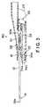
- FIG. 3is a schematic cross-sectional view of a needle assembly comprising the needle component of FIG. 1 A and the blunting component of FIG. 2A ;
- FIGS. 4A and 4Bare schematic cross-sectional views illustrating the operation of a release accessory with the detent of the blunting component of FIG. 2A ;
- FIGS. 5A and 5Bare schematic cross-sectional views of a self-blunting catheter assembly in accordance with one embodiment of the invention, comprising the needle assembly of FIG. 3 in the blunted and released configurations, respectively;
- FIG. 6is a partial cross-sectional view of a blunting probe and the piston portion of a shuttle member in accordance with another embodiment of the invention.
- FIGS. 7 and 8are partial perspective views of blunting probes and piston portions of shuttle members in accordance with two further embodiments of the invention.
- FIG. 9is a schematic cross-sectional view of a blunting component for a needle assembly according to still another embodiment of this invention.
- the present inventionpertains to the configuration of a hollow, open-ended blunting probe mounted on a shuttle structure in a needle assembly such that the end of the blunting probe is open for fluid flow.
- the end of the blunting probeis secured in a non-perforating cavity (e.g., a slot, well, etc.) formed in the shuttle structure.
- the blunting probemay simply be attached to the shuttle structure in a manner which leaves the end of the blunting probe open.
- the blunting probemay be mounted in a bore which perforates the shuttle member to provide a flow path through the shuttle member.
- the needle assemblycomprises a fluid chamber into which fluid may flow from the open end of the blunting probe.
- the fluid chambermay be formed in the housing on which the needle is mounted or on the shuttle structure.
- the needle component and the blunting component of the needle assemblyare preferably configured so that the blunting probe can be received telescopically within the needle cannula and can be moved from a blunting position in which the blunt end of the blunting probe protrudes forward beyond the insertion tip of the needle, to blunt the assembly, and a retracted position (the “sharpened configuration”) in which the blunt tip of the blunting probe is withdrawn rearward into the needle, leaving the sharp needle tip exposed.
- the present inventioncan optionally be practiced with a non-perforated blunting probe (i.e., the blunting probe may consist of a hollow tube open only at the ends) and will still provide fluid flow from the blunting probe to the fluid chamber.
- a non-perforated blunting probei.e., the blunting probe may consist of a hollow tube open only at the ends
- the step of perforating a blunting probe to permit such flow through the probe wallis an expensive processing step which may be omitted by the practice of the invention.
- Needle component 10comprises a needle cannula 12 mounted in a housing 16 .
- Needle cannula 12has a sharp puncture tip 14 for penetrating a patient's skin and other tissues and a passageway (unnumbered) that extends through the cannula and which opens into a chamber 16 a in housing 16 .
- Needle component 10is preferably dimensioned and configured to facilitate the handling of needle cannula 12 for convenient connection to other devices and may include structural features intended for specific environments of use.
- housing 16may comprise a fluid chamber 20 into which blood can flow from needle cannula 12 .
- housing 16is translucent or transparent so that the user can see blood flow into chamber 20 as a signal that needle cannula 12 is properly positioned, i.e., housing 16 may comprise a flash chamber for blood flash visualization.
- chamber 20may have an access port 21 for fluid flow therethrough. Port 21 is preferably configured to receive other devices such as a dosage syringe or fluid delivery tube or for luer access.
- Housing 16also defines a port 18 a for receiving the blunting component 26 ( FIG. 2A ) as described further below.
- Needle component 10may optionally be configured for a locking engagement with a blunting component.
- needle component 10comprises a stay 22 that will engage a blunting component as described below.
- Stay 22may be positioned at any convenient point on needle component 10 but, in the illustrated embodiment, stay 22 is formed as the shoulder at the end of a sloped incline in a U-shaped guide 24 that is on housing 16 but outside of the chamber 16 a.
- Needle component 10defines a port 18 a which is preferably fitted with a bushing 54 , for receiving the blunting component and through which a blunting probe may be inserted into needle cannula 12 via chamber 16 a , as described below.
- Bushing 54is an O-ring providing both a sealing function and a guiding function.
- FIGS. 2A and 2BA blunting component in accordance with one embodiment of the present invention suitable for use with needle component 10 is shown in FIGS. 2A and 2B .
- Blunting component 26comprises a hollow, unperforated blunting probe 28 that has a distal, open blunt tip 28 a and an opposite open end 28 b .
- Blunting probe 28is carried on a shuttle 30 .
- Shuttle 30comprises a piston portion 30 a and a base portion 32 which comprises a resilient, spring-like detent 34 .
- Shuttle 30has, in piston portion 30 a , a non-perforating cavity for receiving the blunting probe 28 .
- the non-perforating cavitycomprises a slot 30 b sized to receive blunting probe 28 therein.
- a bead of adhesivemay be applied to blunting probe 28 , near the open end and blunting probe 28 may then be positioned in slot 30 b .
- the type and amount of adhesive 30 c and the size of slot 30 b and of blunting probe 28 which permit blunting probe 28 to be mounted in slot 30 b without causing the adhesive to occlude the open end of blunting probe 28can be readily determined by one of ordinary skill in the art without undue experimentation.
- Blunting probe 28is disposed in slot 30 b with its end open for fluid flow through slot 30 b and the adhesive is then cured.
- a UV-curable adhesivehas been found to work well in this approach, but any other type of suitable adhesive may be used.
- open end 28 bis open to fluid flow into the slot and, from the slot, into a surrounding region in the needle member, as will be described further below.
- Blunting probe 28( FIG. 2A ) is configured so that it can be inserted into probe port 18 a ( FIG. 1A ) and thus be telescopically disposed within needle cannula 12 .
- Piston portion 30 a on shuttle 30is configured to be movably received in port 18 a ( FIGS. 1A and 1B ) and to form a seal with port 18 a about bushing 54 .
- the piston portion 30 athus extends into chamber 16 a (FIG. 1 A).
- Base portion 32extends outside of chamber 16 a where it carries detent 34 which comprises a lug 34 a that is dimensioned and configured to engage stay 22 of needle component 10 (FIGS. 1 A and 1 B), as will be described below.
- Detent 34also carries a coupling site 34 b defined by an oblique flange 36 and a coupling shoulder 38 .
- Shuttle 30( FIG. 2A ) is dimensioned and configured so that when blunting probe 28 is thus inserted into needle cannula 12 (FIG. 1 A), detent 34 can be received within guide 24 and can move axially within channel 24 a .
- the portions of shuttle 30 outside fluid chamber 20are used to control the movement of the shuttle 30 and the blunting probe 28 thereon relative to the needle component 10 .
- Shuttle 30 and guide 24are dimensioned and configured so that detent 34 is biased to engage stay 22 .
- Detent 34is movable between a locking position in which it inhibits movement of the blunting component to an unlocked position in which it permits movement of the blunting component, as described further herein.
- needle component 10 and blunting component 30can be assembled to produce a self-blunting needle assembly 40 shown in FIG. 3 .
- FIG. 3shows needle assembly 40 in the blunted configuration, i.e., with blunting probe 28 disposed telescopically within needle 12 and positioned therein so that blunt tip 28 a protrudes beyond puncture tip 14 and thus blunts needle assembly 40 .
- lug 34 a on blunting component 26FIGS. 2A and 213 ) outside of chamber 16 a ( FIG.
- needle assembly 40engages stay 22 on needle component 10 . Accordingly, even if axial pressure is applied on blunt tip 28 a , movement of blunt tip 28 a into needle cannula 12 (exposing puncture tip 14 ) is prevented because lug 34 a of detent 34 bears against stay 22 , thus preventing rearward axial movement (as sensed relative to needle cannula 12 ) of blunting probe 28 . Thus, needle assembly 40 is locked in the blunted configuration in which it will protect users against accidental needle sticks. However, needle assembly 40 is releasably locked in the blunted configuration. To release the blunting component in needle assembly 40 as shown in FIG. 3 , it is necessary to disengage lug 34 a from stay 22 .
- guide 24is dimensioned and configured to permit the flexure of detent 34 to permit lug 34 a to be moved upward (as sensed in FIG. 3 ) for a distance sufficient to disengage lug 34 a from stay 22 .
- blunting component 26is free to slide within guide 24 for a distance sufficient for blunt tip 28 a to be withdrawn into needle cannula 12 , thus exposing puncture tip 14 .
- Guide 24is open-ended so that detent 34 is accessible from outside guide 24 .
- Coupling site 34 b on detent 34is especially accessible and is dimensioned and configured to engage an accessory device that is used to raise lug 34 a away from stay 22 .
- a suitable accessoryis partially illustrated in FIGS. 4A and 4B .
- Accessory 42carries a pawl 44 that is dimensioned and configured to enter channel 24 a ( FIG. 3 ) and to engage coupling site 34 b .
- pawl 44initially engages flange 36 . Due to the slanted internal configuration of flange 36 , movement of accessory 42 in a substantially rearward direction causes flange 36 to rise, as sensed in FIG.
- Flange 36 and coupling site 34 bare dimensioned and configured so that the rearward movement of accessory 42 flexes detent 34 to a degree sufficient to disengage lug 34 a from stay 22 (shown in FIG. 3 ).
- a coupling surface 44 a on pawl 44is disposed against coupling shoulder 38 , as shown in FIG. 4B , which shows the elevated, disengaged (i.e., released) position of detent 34 and, in dotted outline, the locked position of detent 34 .
- One advantage of the illustrated embodimentis that the releasable locking mechanism is enclosed within guide 24 , thus reducing the likelihood of inadvertent release of blunting component 26 , that could lead to, or allow, an accidental needle stick.
- an accessoryhas an injection port dimensioned and configured to receive the needle assembly and engage the coupling site.
- the catheter hubis dimensioned and configured to receive the needle assembly and engage the coupling site.
- an accessorymay comprise part of a catheter assembly comprising a catheter hub on the end of a catheter tube.
- the catheter tubeis sized to receive the needle cannula therein and the catheter hub is dimensioned and configured to engage the hub portion of the needle component.
- needle cannula 12blunted by blunt tip 28 a of blunting probe 28 , is inserted into and through catheter 46 .
- Catheter 46comprises a catheter tube 46 a and a catheter hub 46 b which is dimensioned and configured to receive hub portion 18 of needle component 10 .
- Hub 46 bcomprises an accessory flange 46 c that is dimensioned and configured to enter U-shaped guide 24 and to engage the coupling site 34 b on detent 34 as shown in FIGS. 4A and 4B .
- catheter 46 and needle assembly 40constitutes an accessory-needle apparatus in accordance with one embodiment of the present invention.
- Catheter 46 and needle assembly 40are dimensioned and configured so that, when catheter 46 is fully mounted on hub portion 18 of needle component 10 , the end of catheter 46 is drawn past the puncture tip of needle cannula 12 .
- catheter hub 46 bis moved axially rearward along needle cannula 12 . Such motion causes accessory flange 46 c to engage coupling site 34 b as shown in FIGS. 4A and 4B .
- accessory flange 46 cengages coupling site 34 b
- a slight rearward motion of catheter hub 46 bdisengages lug 34 a from stay 22 . Further rearward motion of catheter tube 46 towards full engagement with needle component 10 , as shown in FIG.
- blunting probe 28is hollow and open only at the ends. Needle assembly 40 is configured, however, so that even when it is in the sharpened configuration shown in FIG. 5B , fluid can flow out of open end 28 b , through slot 30 b and into fluid chamber 20 of needle component 10 .
- the fully assembled apparatus 50 in the sharpened configuration of FIG. 5Bcan be used to effect venipuncture with puncture tip 14 to introduce catheter tube 46 into the vein.
- Proper positioning of needle 12 into the veinis indicated by the flow of blood through needle cannula 12 , into hollow blunting probe 28 and out the open end 28 b ( FIG. 2A ) thereof, through slot 30 b ( FIG. 2A ) and through access opening 52 ( FIG. 5B ) in needle component 10 to fluid chamber 20 .
- needle component 10comprises bushing 54 that is dimensioned and configured to engage shuttle 30 in a manner that permits movement of blunting component 26 between sharpened and blunted configurations while preventing fluid flow into U-shaped guide 24 .
- This aspect of this inventionthus pertains to an assembly in which the blunting component shuttle is disposed partially within a fluid chamber in the assembly, and is configured to extend from the interior of the fluid chamber to its exterior so that the blunting component can be manipulated by contact with a structure outside the chamber.
- shuttle 30which is dimensioned and configured for this purpose, but other embodiments will be obvious to those skilled in the art, after reading this disclosure.
- the needle assembly 40is withdrawn from catheter 46 .
- accessory flange 46 cpulls blunting component 26 forward in needle component 10 (i.e., towards puncture tip 14 ) by engaging coupling shoulder 38 (FIG. 4 B).
- lug 34 aslides past stay 22 and needle assembly 40 is further withdrawn from catheter 46 , lug 34 a is moved into position to engage stay 22 and accessory flange 46 c is disengaged from coupling site 34 b . Accordingly, spring-like detent 34 moves downward, causing lug 34 a to engage stay 22 .
- blunting component 26in needle component 10 in the blunted configuration, i.e., with blunt tip 28 a of blunting probe 28 extending beyond puncture tip 14 . Due to the length of needle cannula 12 and blunting probe 28 , needle assembly 40 becomes locked in the blunted configuration even before needle cannula 12 is fully withdrawn from catheter 46 .
- the location of stay 22 ( FIG. 1A ) and corresponding lug 34 a ( FIG. 2A )can be varied as matters of mere design choice.
- a variety of locking mechanisms that are releasable by the use of an accessory into which the needle is insertedcan be employed.
- the present inventioncan be practiced in various alternative embodiments, all of which permit fluid to flow from the open end of the blunting probe into the needle member chamber.
- the piston portion of the blunting member shuttleinstead of being slotted, may be perforated by a two-ended bore as suggested in FIG. 6 .
- the open end of blunting probe 28is inserted into the opening of bore 30 b ′ at the forward end of piston portion 30 a ′.
- Bore 30 b ′permits fluid to flow therethrough from the open end of blunting probe 28 to the needle component chamber.
- the blunting probemay extend through the perforation in the piston portion so that fluid appears to flow directly from the open end of the blunting probe into the needle chamber.
- the cavity into which blunting probe 28 is insertedmay be a non-perforating well configured to permit fluid to flow out the open end of blunting probe 28 and then forward along the blunting probe 28 and out the end of the piston portion, as suggested in FIG. 7 .
- FIG. 8shows an alternative configuration in which the piston portion 30 a ′′ carries a mounting extension 31 a shaped like a chisel blade which is configured to be inserted and secured within the open end 28 b of blunting probe 28 without blocking fluid flow therethrough.
- Various other mounting extensionscan be used to permit the blunting member to be advanced and retracted by movement of the shuttle without obstructing fluid flow from the open end thereof into the fluid chamber of the needle member.
- the mounting extensionmay be in the form of a helical spring, a substantially straight wire or rod, etc., joining the piston portion to the blunting probe without obstructing fluid flow from the end of the blunting probe.
- FIG. 9A blunting component for a needle assembly in accordance with yet another embodiment of the present invention is shown in FIG. 9 .
- Blunting component 126comprises a shuttle 130 on which is carried a blunting probe 128 .
- Blunting probe 128is hollow and open at both ends but is otherwise unperforated.
- Blunting probe 128is mounted on shuttle 130 with an open end open for fluid flow to fluid chamber 116 .
- Chamber 116may define an opening 121 having a standard configuration for connection to other devices, e.g., a luer access.
- part of the structure defining chamber 116may be transparent or translucent, thus allowing chamber 116 to serve as a flash chamber.
- Shuttle 130comprises a detent 134 which is configured for a releasable locking engagement with a needle component and, optionally, for engagement with an accessory device such as a catheter, in substantially the same manner as detent 34 ( FIG. 2A ) of shuttle 30 .
- blunting component 126 and a complementary needle componentcan be configured so that blunting probe 128 is inserted into a needle cannula and is movable between a blunted configuration and a sharpened configuration, in substantially the same manner as apparatus 50 , FIGS. 5A and 5B .
- blunting probe 128is mounted in a bore which perforates shuttle 130 .
Landscapes
- Health & Medical Sciences (AREA)
- Life Sciences & Earth Sciences (AREA)
- Biophysics (AREA)
- Pulmonology (AREA)
- Engineering & Computer Science (AREA)
- Anesthesiology (AREA)
- Biomedical Technology (AREA)
- Heart & Thoracic Surgery (AREA)
- Hematology (AREA)
- Animal Behavior & Ethology (AREA)
- General Health & Medical Sciences (AREA)
- Public Health (AREA)
- Veterinary Medicine (AREA)
- Infusion, Injection, And Reservoir Apparatuses (AREA)
- Measuring Leads Or Probes (AREA)
Abstract
Description
Claims (10)
Priority Applications (13)
| Application Number | Priority Date | Filing Date | Title |
|---|---|---|---|
| US09/757,138US6837878B2 (en) | 2001-01-09 | 2001-01-09 | Bluntable needle assembly with open-ended blunting probe |
| EP02718794AEP1357962A4 (en) | 2001-01-09 | 2002-01-08 | Bluntable needle assembly with open-ended blunting probe |
| CNA028035739ACN1496273A (en) | 2001-01-09 | 2002-01-08 | Bluntable needle assembly with open-ended blunting prode |
| BR0206357-3ABR0206357A (en) | 2001-01-09 | 2002-01-08 | Blunt needle assembly with open end blunt probe |
| NZ526911ANZ526911A (en) | 2001-01-09 | 2002-01-08 | Bluntable needle assembly with open-ended blunting probe |
| AU2002249912AAU2002249912A2 (en) | 2001-01-09 | 2002-01-08 | Bluntable needle assembly with open-ended blunting probe |
| PCT/US2002/000301WO2002062410A1 (en) | 2001-01-09 | 2002-01-08 | Bluntable needle assembly with open-ended blunting probe |
| CA002433913ACA2433913A1 (en) | 2001-01-09 | 2002-01-08 | Bluntable needle assembly with open-ended blunting probe |
| JP2002562415AJP2004522527A (en) | 2001-01-09 | 2002-01-08 | Non-sharpening needle assembly including non-sharp probe with open end |
| MXPA03006056AMXPA03006056A (en) | 2001-01-09 | 2002-01-08 | Bluntable needle assembly with open-ended blunting probe. |
| NO20033072ANO20033072L (en) | 2001-01-09 | 2003-07-04 | Stubby needle assembly with open stub probe |
| ZA200306153AZA200306153B (en) | 2001-01-09 | 2003-08-08 | Bluntable needle assembly wiith open-ended blunting probe. |
| US11/018,014US20050113758A1 (en) | 2001-01-09 | 2004-12-20 | Bluntable needle assembly with open-ended blunting probe |
Applications Claiming Priority (1)
| Application Number | Priority Date | Filing Date | Title |
|---|---|---|---|
| US09/757,138US6837878B2 (en) | 2001-01-09 | 2001-01-09 | Bluntable needle assembly with open-ended blunting probe |
Related Child Applications (1)
| Application Number | Title | Priority Date | Filing Date |
|---|---|---|---|
| US11/018,014ContinuationUS20050113758A1 (en) | 2001-01-09 | 2004-12-20 | Bluntable needle assembly with open-ended blunting probe |
Publications (2)
| Publication Number | Publication Date |
|---|---|
| US20020095123A1 US20020095123A1 (en) | 2002-07-18 |
| US6837878B2true US6837878B2 (en) | 2005-01-04 |
Family
ID=25046519
Family Applications (2)
| Application Number | Title | Priority Date | Filing Date |
|---|---|---|---|
| US09/757,138Expired - LifetimeUS6837878B2 (en) | 2001-01-09 | 2001-01-09 | Bluntable needle assembly with open-ended blunting probe |
| US11/018,014AbandonedUS20050113758A1 (en) | 2001-01-09 | 2004-12-20 | Bluntable needle assembly with open-ended blunting probe |
Family Applications After (1)
| Application Number | Title | Priority Date | Filing Date |
|---|---|---|---|
| US11/018,014AbandonedUS20050113758A1 (en) | 2001-01-09 | 2004-12-20 | Bluntable needle assembly with open-ended blunting probe |
Country Status (12)
| Country | Link |
|---|---|
| US (2) | US6837878B2 (en) |
| EP (1) | EP1357962A4 (en) |
| JP (1) | JP2004522527A (en) |
| CN (1) | CN1496273A (en) |
| AU (1) | AU2002249912A2 (en) |
| BR (1) | BR0206357A (en) |
| CA (1) | CA2433913A1 (en) |
| MX (1) | MXPA03006056A (en) |
| NO (1) | NO20033072L (en) |
| NZ (1) | NZ526911A (en) |
| WO (1) | WO2002062410A1 (en) |
| ZA (1) | ZA200306153B (en) |
Cited By (55)
| Publication number | Priority date | Publication date | Assignee | Title |
|---|---|---|---|---|
| US20050035014A1 (en)* | 2001-12-28 | 2005-02-17 | Mario Cane | Container for disposable needle or cannula |
| US20050113758A1 (en)* | 2001-01-09 | 2005-05-26 | Smutney Chad C. | Bluntable needle assembly with open-ended blunting probe |
| US20060036214A1 (en)* | 2004-08-10 | 2006-02-16 | Mogensen Lasse W | Cannula device |
| US20080039794A1 (en)* | 2004-03-20 | 2008-02-14 | Grete Kornerup | Injection Device for Infusion Set |
| US20090076453A1 (en)* | 2005-12-23 | 2009-03-19 | Signe Thorning Mejlhede | Device for Administration |
| US20090157013A1 (en)* | 2007-11-21 | 2009-06-18 | Becton, Dickinson And Company | Needle safety device |
| US20090198190A1 (en)* | 2005-03-21 | 2009-08-06 | Soren Jensen | Mounting Pad, an Adhesive Device Comprising Such Mounting Pad, and Method of Applying Such Devices to a Patient |
| US20090204077A1 (en)* | 2008-02-13 | 2009-08-13 | Hasted Soren B | Moulded Connection Between Cannula and Delivery Part |
| US20090216201A1 (en)* | 2007-11-21 | 2009-08-27 | Becton, Dickinson And Company | Safety Needle Guard |
| US20090218243A1 (en)* | 2006-02-13 | 2009-09-03 | Unomedical A/S | Packing for Injection Device |
| US20100022863A1 (en)* | 2006-06-07 | 2010-01-28 | Mogensen Lasse W | Inserter for Transcutaneous Sensor |
| US20100022960A1 (en)* | 2006-02-28 | 2010-01-28 | Mejlhede Signe T | Inserter for Infusion Part and Infusion Part Provided with Needle Protector |
| US20100063453A1 (en)* | 2007-02-02 | 2010-03-11 | Julie Grundtvig Theander | Gateway Device |
| US20100152665A1 (en)* | 2007-06-20 | 2010-06-17 | Hasted Soeren Bo | Cannula Insertion Device with Automatic Needle Retraction Comprising Only One Spring |
| US20100179508A1 (en)* | 2005-06-28 | 2010-07-15 | Unomedical A/S | Packing for an infusion set and method of applying an infusion set |
| US20100198157A1 (en)* | 2007-05-07 | 2010-08-05 | Steffen Gyrn | Cannula and Delivery Device |
| US20100204653A1 (en)* | 2007-07-18 | 2010-08-12 | Unomedical A/S | Insertion device with pivoting action |
| US20100274200A1 (en)* | 2007-06-06 | 2010-10-28 | Jens Egebjerg Nielsen | Packing Allowing Gas Sterilization |
| US20110034883A1 (en)* | 2008-02-13 | 2011-02-10 | Steffen Gyrn | Sealing Between a Cannula Part and a Fluid Path |
| US20110036844A1 (en)* | 2008-02-25 | 2011-02-17 | Unomedical A/S | Bubble Shaped Membrane and Use of Such Membrane in a Device |
| US20110040263A1 (en)* | 2008-02-08 | 2011-02-17 | Unomedical A/S | Inserter Assembly |
| US20110046456A1 (en)* | 2008-02-08 | 2011-02-24 | Hoerdum Elo Lau | Assembly Comprising Inserter, Cannula Part and Base Part |
| US20110137257A1 (en)* | 2008-07-07 | 2011-06-09 | Unomedical A/S | Inserter for Transcutaneous Device |
| US20110152778A1 (en)* | 2006-06-09 | 2011-06-23 | Unomedical A/S | Mounting Pad |
| US7985199B2 (en) | 2005-03-17 | 2011-07-26 | Unomedical A/S | Gateway system |
| US8012126B2 (en) | 2006-10-31 | 2011-09-06 | Unomedical A/S | Infusion set |
| US20110226652A1 (en)* | 2008-09-29 | 2011-09-22 | Richard Morgan Hickmott | Packing for Inserter |
| US8430850B2 (en) | 2007-07-03 | 2013-04-30 | Unomedical A/S | Inserter having bistable equilibrium states |
| US8486003B2 (en) | 2007-07-10 | 2013-07-16 | Unomedical A/S | Inserter having two springs |
| US20130267980A1 (en)* | 2012-03-13 | 2013-10-10 | Smith & Nephew, Inc. | Surgical needle |
| US8562567B2 (en) | 2009-07-30 | 2013-10-22 | Unomedical A/S | Inserter device with horizontal moving part |
| US8945057B2 (en) | 2006-08-02 | 2015-02-03 | Unomedical A/S | Cannula and delivery device |
| US9186480B2 (en) | 2007-06-20 | 2015-11-17 | Unomedical A/S | Apparatus for making a catheter |
| US9254373B2 (en) | 2008-12-22 | 2016-02-09 | Unomedical A/S | Medical device comprising adhesive pad |
| US9283331B2 (en) | 2010-11-30 | 2016-03-15 | University Of Utah Research Foundation | Hypodermic needle system and method of use to reduce infection |
| US9415159B2 (en) | 2010-03-30 | 2016-08-16 | Unomedical A/S | Medical device |
| US9440051B2 (en) | 2011-10-27 | 2016-09-13 | Unomedical A/S | Inserter for a multiplicity of subcutaneous parts |
| US20160287793A1 (en)* | 2015-04-02 | 2016-10-06 | XEND Medical, LLC | Hypodermic needle system having plunger |
| US9533092B2 (en) | 2009-08-07 | 2017-01-03 | Unomedical A/S | Base part for a medication delivery device |
| US9566384B2 (en) | 2008-02-20 | 2017-02-14 | Unomedical A/S | Insertion device with horizontally moving part |
| US9724127B2 (en) | 2010-09-27 | 2017-08-08 | Unomedical A/S | Insertion system and insertion kit |
| US9726314B2 (en) | 2010-04-05 | 2017-08-08 | Dr. Py Institute Llc | Aseptic connector with deflectable ring of concern and method |
| US9895165B2 (en) | 2013-03-15 | 2018-02-20 | Smith & Nephew, Inc. | Surgical needle |
| US9951899B2 (en) | 2012-04-17 | 2018-04-24 | Dr. Py Institute, Llc | Self closing connector |
| US9989177B2 (en) | 2012-05-01 | 2018-06-05 | Dr. Py Institute Llc | Device for connecting or filling and method |
| US10351271B2 (en) | 2012-05-01 | 2019-07-16 | Dr. Py Institute Llc | Device for connecting or filling and method |
| US10369277B2 (en) | 2005-09-12 | 2019-08-06 | Unomedical A/S | Invisible needle |
| US10426701B2 (en) | 2016-01-19 | 2019-10-01 | Medinstill Development Llc | Single use connectors |
| US10499903B2 (en) | 2014-10-15 | 2019-12-10 | Smith & Nephew, Inc. | Anchor/implant deployment device and tissue repair methods related thereto |
| US10499904B2 (en) | 2015-02-17 | 2019-12-10 | Smith & Nephew, Inc. | Anchor insertion system and method of use thereof |
| US11020526B2 (en) | 2010-10-04 | 2021-06-01 | Unomedical A/S | Sprinkler cannula |
| US11110261B2 (en) | 2011-10-19 | 2021-09-07 | Unomedical A/S | Infusion tube system and method for manufacture |
| US11197689B2 (en) | 2011-10-05 | 2021-12-14 | Unomedical A/S | Inserter for simultaneous insertion of multiple transcutaneous parts |
| US12097984B2 (en) | 2011-04-18 | 2024-09-24 | Dr. Py Institute Llc | Needle with closure and method |
| WO2025166321A1 (en)* | 2024-02-02 | 2025-08-07 | Chambers Justin R | Device and method to obtain synovial fluid and biofilm samples |
Families Citing this family (9)
| Publication number | Priority date | Publication date | Assignee | Title |
|---|---|---|---|---|
| US20050096594A1 (en)* | 2002-04-30 | 2005-05-05 | Doctor's Research Group, Incorporated | Cannula arrangements |
| US8021338B2 (en)* | 2005-09-14 | 2011-09-20 | Boston Scientific Scimed, Inc. | Percutaneous endoscopic jejunostomy access needle |
| US20090061389A1 (en) | 2007-08-30 | 2009-03-05 | Matthew Lomicka | Dental implant prosthetic device with improved osseointegration and shape for resisting rotation |
| US8562348B2 (en)* | 2008-07-02 | 2013-10-22 | Zimmer Dental, Inc. | Modular implant with secured porous portion |
| US20100114314A1 (en) | 2008-11-06 | 2010-05-06 | Matthew Lomicka | Expandable bone implant |
| GB2503668B (en) | 2012-07-03 | 2018-02-07 | Univ Hospitals Of Leicester Nhs Trust | Delivery apparatus |
| CN108852472B (en)* | 2018-06-18 | 2025-01-28 | 无锡市人民医院 | Self-locking safety Veress needle |
| CN108721730B (en)* | 2018-07-02 | 2023-06-02 | 中国人民解放军总医院 | Injector for viscous medicinal liquids |
| EP4196204A4 (en)* | 2020-08-13 | 2024-09-11 | New York Society for the Relief of the Ruptured and Crippled, Maintaining the Hospital for Special Surgery | IV CATHETER DEVICE |
Citations (14)
| Publication number | Priority date | Publication date | Assignee | Title |
|---|---|---|---|---|
| US4627841A (en) | 1986-02-18 | 1986-12-09 | Dorr Robert T | Infusion needle |
| US4828547A (en)* | 1987-09-28 | 1989-05-09 | Bio-Plexus, Inc. | Self-blunting needle assembly and device including the same |
| US5009642A (en) | 1987-09-28 | 1991-04-23 | Bio-Plexus, Inc. | Self-blunting needle assembly for use with a catheter, and catheter assembly using the same |
| US5092851A (en) | 1991-01-04 | 1992-03-03 | Ragner & Staab Associates | Safety needle with spring-loaded shield |
| US5312345A (en) | 1992-03-11 | 1994-05-17 | Cole Richard D | Anti-needle stick protective inner blunt tubular stylet for intravenous therapy |
| US5480389A (en)* | 1994-08-09 | 1996-01-02 | Becton, Dickinson And Company | Method and apparatus for adjusting the length of a combined spinal-epidural needle |
| US5697914A (en) | 1995-03-16 | 1997-12-16 | Becton Dickinson And Company | Control forward/flashback forward one hand introducer needle and catheter assembly |
| US5743882A (en) | 1996-03-08 | 1998-04-28 | Luther Medical Products, Inc. | Needle blunting assembly for use with intravascular introducers |
| US5817060A (en) | 1996-03-08 | 1998-10-06 | Luther Medical Products, Inc. | Unidirectional blunting apparatus for hypodermic needles |
| US5951520A (en) | 1996-12-19 | 1999-09-14 | Bio-Plexus, Inc. | Self-blunting needle medical devices and methods of manufacture thereof |
| US6056726A (en)* | 1994-02-28 | 2000-05-02 | Isaacson; Dennis Ray | Self-contained safety intravenous catheter insertion device |
| US6391007B2 (en)* | 1998-12-23 | 2002-05-21 | Joseph Jawshin Chang | Solid blunt for a needle assembly |
| US6544239B2 (en)* | 1998-10-16 | 2003-04-08 | Bio-Plexus Delaware, Inc. | Releasable locking needle assembly with optional release accessory therefor |
| US6623456B1 (en) | 1998-10-16 | 2003-09-23 | Bio-Plexus, Inc. | Needle member with off-set flash chamber and/or display member |
Family Cites Families (4)
| Publication number | Priority date | Publication date | Assignee | Title |
|---|---|---|---|---|
| US4863431A (en)* | 1988-03-03 | 1989-09-05 | Vaillancourt Vincent L | Catheter assembly |
| DE69828621T2 (en)* | 1997-03-26 | 2005-06-16 | Bio-Plexus, Inc., Vernon | DEVICE FOR TRANSFERING A PARENTERAL LIQUID |
| US6210379B1 (en)* | 1999-12-02 | 2001-04-03 | Ethicon, Inc. | Needle assembly having an elongated blunting device which allows for venting of air |
| US6837878B2 (en)* | 2001-01-09 | 2005-01-04 | Icu Medical, Inc. | Bluntable needle assembly with open-ended blunting probe |
- 2001
- 2001-01-09USUS09/757,138patent/US6837878B2/ennot_activeExpired - Lifetime
- 2002
- 2002-01-08AUAU2002249912Apatent/AU2002249912A2/ennot_activeAbandoned
- 2002-01-08WOPCT/US2002/000301patent/WO2002062410A1/enactiveIP Right Grant
- 2002-01-08EPEP02718794Apatent/EP1357962A4/ennot_activeWithdrawn
- 2002-01-08BRBR0206357-3Apatent/BR0206357A/ennot_activeIP Right Cessation
- 2002-01-08CACA002433913Apatent/CA2433913A1/ennot_activeAbandoned
- 2002-01-08JPJP2002562415Apatent/JP2004522527A/enactivePending
- 2002-01-08NZNZ526911Apatent/NZ526911A/enunknown
- 2002-01-08CNCNA028035739Apatent/CN1496273A/enactivePending
- 2002-01-08MXMXPA03006056Apatent/MXPA03006056A/enunknown
- 2003
- 2003-07-04NONO20033072Apatent/NO20033072L/ennot_activeApplication Discontinuation
- 2003-08-08ZAZA200306153Apatent/ZA200306153B/enunknown
- 2004
- 2004-12-20USUS11/018,014patent/US20050113758A1/ennot_activeAbandoned
Patent Citations (16)
| Publication number | Priority date | Publication date | Assignee | Title |
|---|---|---|---|---|
| US4627841A (en) | 1986-02-18 | 1986-12-09 | Dorr Robert T | Infusion needle |
| US4828547A (en)* | 1987-09-28 | 1989-05-09 | Bio-Plexus, Inc. | Self-blunting needle assembly and device including the same |
| US5009642A (en) | 1987-09-28 | 1991-04-23 | Bio-Plexus, Inc. | Self-blunting needle assembly for use with a catheter, and catheter assembly using the same |
| US5092851A (en) | 1991-01-04 | 1992-03-03 | Ragner & Staab Associates | Safety needle with spring-loaded shield |
| US5312345A (en) | 1992-03-11 | 1994-05-17 | Cole Richard D | Anti-needle stick protective inner blunt tubular stylet for intravenous therapy |
| US6056726A (en)* | 1994-02-28 | 2000-05-02 | Isaacson; Dennis Ray | Self-contained safety intravenous catheter insertion device |
| US5480389A (en)* | 1994-08-09 | 1996-01-02 | Becton, Dickinson And Company | Method and apparatus for adjusting the length of a combined spinal-epidural needle |
| US5697914A (en) | 1995-03-16 | 1997-12-16 | Becton Dickinson And Company | Control forward/flashback forward one hand introducer needle and catheter assembly |
| US5817060A (en) | 1996-03-08 | 1998-10-06 | Luther Medical Products, Inc. | Unidirectional blunting apparatus for hypodermic needles |
| US5743882A (en) | 1996-03-08 | 1998-04-28 | Luther Medical Products, Inc. | Needle blunting assembly for use with intravascular introducers |
| US6106499A (en) | 1996-03-08 | 2000-08-22 | Luther Medical Products, Inc. | Unidirectional blunting apparatus for hypodermic needles |
| US5951520A (en) | 1996-12-19 | 1999-09-14 | Bio-Plexus, Inc. | Self-blunting needle medical devices and methods of manufacture thereof |
| US6254574B1 (en)* | 1996-12-19 | 2001-07-03 | Bio-Plexus, Inc. | Self-blunting needle medical devices and methods of manufacture thereof |
| US6544239B2 (en)* | 1998-10-16 | 2003-04-08 | Bio-Plexus Delaware, Inc. | Releasable locking needle assembly with optional release accessory therefor |
| US6623456B1 (en) | 1998-10-16 | 2003-09-23 | Bio-Plexus, Inc. | Needle member with off-set flash chamber and/or display member |
| US6391007B2 (en)* | 1998-12-23 | 2002-05-21 | Joseph Jawshin Chang | Solid blunt for a needle assembly |
Cited By (80)
| Publication number | Priority date | Publication date | Assignee | Title |
|---|---|---|---|---|
| US20050113758A1 (en)* | 2001-01-09 | 2005-05-26 | Smutney Chad C. | Bluntable needle assembly with open-ended blunting probe |
| US7407493B2 (en) | 2001-12-28 | 2008-08-05 | Unomedical A/S | Container for disposable needle or cannula |
| US20050035014A1 (en)* | 2001-12-28 | 2005-02-17 | Mario Cane | Container for disposable needle or cannula |
| US20080039794A1 (en)* | 2004-03-20 | 2008-02-14 | Grete Kornerup | Injection Device for Infusion Set |
| US8221355B2 (en) | 2004-03-26 | 2012-07-17 | Unomedical A/S | Injection device for infusion set |
| US8287516B2 (en) | 2004-03-26 | 2012-10-16 | Unomedical A/S | Infusion set |
| US8062250B2 (en) | 2004-08-10 | 2011-11-22 | Unomedical A/S | Cannula device |
| US20060036214A1 (en)* | 2004-08-10 | 2006-02-16 | Mogensen Lasse W | Cannula device |
| US7985199B2 (en) | 2005-03-17 | 2011-07-26 | Unomedical A/S | Gateway system |
| US20090198190A1 (en)* | 2005-03-21 | 2009-08-06 | Soren Jensen | Mounting Pad, an Adhesive Device Comprising Such Mounting Pad, and Method of Applying Such Devices to a Patient |
| US20100179508A1 (en)* | 2005-06-28 | 2010-07-15 | Unomedical A/S | Packing for an infusion set and method of applying an infusion set |
| US10369277B2 (en) | 2005-09-12 | 2019-08-06 | Unomedical A/S | Invisible needle |
| US20090221971A1 (en)* | 2005-12-23 | 2009-09-03 | Signe Thorning Mejlhede | Injection device |
| US8303549B2 (en) | 2005-12-23 | 2012-11-06 | Unomedical A/S | Injection device |
| US9278173B2 (en) | 2005-12-23 | 2016-03-08 | Unomedical A/S | Device for administration |
| US20090076453A1 (en)* | 2005-12-23 | 2009-03-19 | Signe Thorning Mejlhede | Device for Administration |
| US20090218243A1 (en)* | 2006-02-13 | 2009-09-03 | Unomedical A/S | Packing for Injection Device |
| US20100022960A1 (en)* | 2006-02-28 | 2010-01-28 | Mejlhede Signe T | Inserter for Infusion Part and Infusion Part Provided with Needle Protector |
| US9211379B2 (en) | 2006-02-28 | 2015-12-15 | Unomedical A/S | Inserter for infusion part and infusion part provided with needle protector |
| US8439838B2 (en) | 2006-06-07 | 2013-05-14 | Unomedical A/S | Inserter for transcutaneous sensor |
| US20100022863A1 (en)* | 2006-06-07 | 2010-01-28 | Mogensen Lasse W | Inserter for Transcutaneous Sensor |
| US20110152778A1 (en)* | 2006-06-09 | 2011-06-23 | Unomedical A/S | Mounting Pad |
| US8790311B2 (en) | 2006-06-09 | 2014-07-29 | Unomedical A/S | Mounting pad |
| US8945057B2 (en) | 2006-08-02 | 2015-02-03 | Unomedical A/S | Cannula and delivery device |
| US8012126B2 (en) | 2006-10-31 | 2011-09-06 | Unomedical A/S | Infusion set |
| US20100063453A1 (en)* | 2007-02-02 | 2010-03-11 | Julie Grundtvig Theander | Gateway Device |
| US20100198157A1 (en)* | 2007-05-07 | 2010-08-05 | Steffen Gyrn | Cannula and Delivery Device |
| US20100274200A1 (en)* | 2007-06-06 | 2010-10-28 | Jens Egebjerg Nielsen | Packing Allowing Gas Sterilization |
| US9186480B2 (en) | 2007-06-20 | 2015-11-17 | Unomedical A/S | Apparatus for making a catheter |
| US20100152665A1 (en)* | 2007-06-20 | 2010-06-17 | Hasted Soeren Bo | Cannula Insertion Device with Automatic Needle Retraction Comprising Only One Spring |
| US9320869B2 (en) | 2007-06-20 | 2016-04-26 | Unomedical A/S | Apparatus for making a catheter |
| US8430850B2 (en) | 2007-07-03 | 2013-04-30 | Unomedical A/S | Inserter having bistable equilibrium states |
| US8486003B2 (en) | 2007-07-10 | 2013-07-16 | Unomedical A/S | Inserter having two springs |
| US20100204653A1 (en)* | 2007-07-18 | 2010-08-12 | Unomedical A/S | Insertion device with pivoting action |
| US8246588B2 (en) | 2007-07-18 | 2012-08-21 | Unomedical A/S | Insertion device with pivoting action |
| US8298180B2 (en) | 2007-11-21 | 2012-10-30 | Becton, Dickinson And Company | Safety needle guard |
| US20090216201A1 (en)* | 2007-11-21 | 2009-08-27 | Becton, Dickinson And Company | Safety Needle Guard |
| US9278180B2 (en) | 2007-11-21 | 2016-03-08 | Becton, Dickinson And Company | Needle safety device |
| US20090157013A1 (en)* | 2007-11-21 | 2009-06-18 | Becton, Dickinson And Company | Needle safety device |
| US20110040263A1 (en)* | 2008-02-08 | 2011-02-17 | Unomedical A/S | Inserter Assembly |
| US20110046456A1 (en)* | 2008-02-08 | 2011-02-24 | Hoerdum Elo Lau | Assembly Comprising Inserter, Cannula Part and Base Part |
| US20110034883A1 (en)* | 2008-02-13 | 2011-02-10 | Steffen Gyrn | Sealing Between a Cannula Part and a Fluid Path |
| US10898643B2 (en) | 2008-02-13 | 2021-01-26 | Unomedical A/S | Sealing between a cannula part and a fluid path |
| US20090204077A1 (en)* | 2008-02-13 | 2009-08-13 | Hasted Soren B | Moulded Connection Between Cannula and Delivery Part |
| US9566384B2 (en) | 2008-02-20 | 2017-02-14 | Unomedical A/S | Insertion device with horizontally moving part |
| US10376637B2 (en) | 2008-02-20 | 2019-08-13 | Unomedical A/S | Insertion device with horizontally moving part |
| US20110036844A1 (en)* | 2008-02-25 | 2011-02-17 | Unomedical A/S | Bubble Shaped Membrane and Use of Such Membrane in a Device |
| US20110137257A1 (en)* | 2008-07-07 | 2011-06-09 | Unomedical A/S | Inserter for Transcutaneous Device |
| US20110226652A1 (en)* | 2008-09-29 | 2011-09-22 | Richard Morgan Hickmott | Packing for Inserter |
| US9254373B2 (en) | 2008-12-22 | 2016-02-09 | Unomedical A/S | Medical device comprising adhesive pad |
| US8562567B2 (en) | 2009-07-30 | 2013-10-22 | Unomedical A/S | Inserter device with horizontal moving part |
| US9533092B2 (en) | 2009-08-07 | 2017-01-03 | Unomedical A/S | Base part for a medication delivery device |
| US9415159B2 (en) | 2010-03-30 | 2016-08-16 | Unomedical A/S | Medical device |
| US11786653B2 (en) | 2010-03-30 | 2023-10-17 | Unomedical A/S | Insertion device |
| US9726314B2 (en) | 2010-04-05 | 2017-08-08 | Dr. Py Institute Llc | Aseptic connector with deflectable ring of concern and method |
| US9724127B2 (en) | 2010-09-27 | 2017-08-08 | Unomedical A/S | Insertion system and insertion kit |
| US11020526B2 (en) | 2010-10-04 | 2021-06-01 | Unomedical A/S | Sprinkler cannula |
| US9283331B2 (en) | 2010-11-30 | 2016-03-15 | University Of Utah Research Foundation | Hypodermic needle system and method of use to reduce infection |
| US12097984B2 (en) | 2011-04-18 | 2024-09-24 | Dr. Py Institute Llc | Needle with closure and method |
| US11197689B2 (en) | 2011-10-05 | 2021-12-14 | Unomedical A/S | Inserter for simultaneous insertion of multiple transcutaneous parts |
| US11110261B2 (en) | 2011-10-19 | 2021-09-07 | Unomedical A/S | Infusion tube system and method for manufacture |
| US11684767B2 (en) | 2011-10-19 | 2023-06-27 | Unomedical A/S | Infusion tube system and method for manufacture |
| US12178984B2 (en) | 2011-10-19 | 2024-12-31 | Unomedical A/S | Infusion tube system and method for manufacture |
| US9440051B2 (en) | 2011-10-27 | 2016-09-13 | Unomedical A/S | Inserter for a multiplicity of subcutaneous parts |
| US20130267980A1 (en)* | 2012-03-13 | 2013-10-10 | Smith & Nephew, Inc. | Surgical needle |
| US10531892B2 (en)* | 2012-03-13 | 2020-01-14 | Smith & Nephew, Inc. | Surgical needle |
| US9951899B2 (en) | 2012-04-17 | 2018-04-24 | Dr. Py Institute, Llc | Self closing connector |
| US9989177B2 (en) | 2012-05-01 | 2018-06-05 | Dr. Py Institute Llc | Device for connecting or filling and method |
| US10351271B2 (en) | 2012-05-01 | 2019-07-16 | Dr. Py Institute Llc | Device for connecting or filling and method |
| US9895165B2 (en) | 2013-03-15 | 2018-02-20 | Smith & Nephew, Inc. | Surgical needle |
| US10499903B2 (en) | 2014-10-15 | 2019-12-10 | Smith & Nephew, Inc. | Anchor/implant deployment device and tissue repair methods related thereto |
| US10499904B2 (en) | 2015-02-17 | 2019-12-10 | Smith & Nephew, Inc. | Anchor insertion system and method of use thereof |
| US20160287796A1 (en)* | 2015-04-02 | 2016-10-06 | Xend Medical Systems, Llc | Cartridge system to which a syringe body can be attached |
| US20160287792A1 (en)* | 2015-04-02 | 2016-10-06 | XEND Medical, LLC | Plugged hypodermic needle system |
| US20160287797A1 (en)* | 2015-04-02 | 2016-10-06 | XEND Medical, LLC | Hypodermic needle system having a spacer |
| US20160287794A1 (en)* | 2015-04-02 | 2016-10-06 | Xend Medical Systems, Llc | Hypodermic needle system activation mechanism |
| US20160287795A1 (en)* | 2015-04-02 | 2016-10-06 | XEND Medical, LLC | Method of using a hypodermic needle system |
| US20160287793A1 (en)* | 2015-04-02 | 2016-10-06 | XEND Medical, LLC | Hypodermic needle system having plunger |
| US10426701B2 (en) | 2016-01-19 | 2019-10-01 | Medinstill Development Llc | Single use connectors |
| WO2025166321A1 (en)* | 2024-02-02 | 2025-08-07 | Chambers Justin R | Device and method to obtain synovial fluid and biofilm samples |
Also Published As
| Publication number | Publication date |
|---|---|
| AU2002249912A2 (en) | 2002-08-19 |
| MXPA03006056A (en) | 2005-02-14 |
| NO20033072L (en) | 2003-09-09 |
| WO2002062410B1 (en) | 2002-10-17 |
| EP1357962A4 (en) | 2008-12-10 |
| NZ526911A (en) | 2004-02-27 |
| EP1357962A1 (en) | 2003-11-05 |
| US20050113758A1 (en) | 2005-05-26 |
| NO20033072D0 (en) | 2003-07-04 |
| CA2433913A1 (en) | 2002-08-15 |
| US20020095123A1 (en) | 2002-07-18 |
| WO2002062410A1 (en) | 2002-08-15 |
| ZA200306153B (en) | 2004-08-18 |
| BR0206357A (en) | 2006-01-31 |
| JP2004522527A (en) | 2004-07-29 |
| CN1496273A (en) | 2004-05-12 |
Similar Documents
| Publication | Publication Date | Title |
|---|---|---|
| US6837878B2 (en) | Bluntable needle assembly with open-ended blunting probe | |
| US6544239B2 (en) | Releasable locking needle assembly with optional release accessory therefor | |
| US7018344B2 (en) | Retractable needle shielding device | |
| US5704920A (en) | Manually driven needle shield assembly | |
| US6936036B2 (en) | Blood collection agency | |
| US5957887A (en) | Infusion catheter assembly needle protection device | |
| US7959613B2 (en) | Catheter introducer assembly having safety shielded needle | |
| US5683368A (en) | Controlled motion lock for safety catheter | |
| WO2000023130A1 (en) | Releasable locking needle assembly with optional release accessory therefor | |
| US6582402B1 (en) | Catheter-advancement actuated needle retraction system | |
| EP2298405B1 (en) | Catheter and introducer needle assembly with needle shield | |
| US8133207B2 (en) | Passive activated safety blood collection set | |
| US7422573B2 (en) | Forward blunting wingset with leaf spring driven shield | |
| CN101112638B (en) | Catheter and introducer needle assembly with safety device | |
| EP0646387B1 (en) | Catheter introducer assembly | |
| US20070066960A1 (en) | Needle retraction structure | |
| US20030220587A1 (en) | Medical device | |
| IL118318A (en) | Catheter arrangement with interlocking sequenced guarding members for protecting cannula | |
| AU2012394400B2 (en) | Passive double drive member activated safety blood collection device | |
| US20040116864A1 (en) | Catheter introducer assembly having safety shielded needle before and after use | |
| CA2398450A1 (en) | Needle assembly | |
| US5879331A (en) | Medical devices having needle retraction and needle biasing mechanism | |
| JPH0315481A (en) | Canule inserting device furnished with retreating needle for safety | |
| HK1065967A (en) | Bluntable needle assembly with open-ended blunting probe |
Legal Events
| Date | Code | Title | Description |
|---|---|---|---|
| AS | Assignment | Owner name:COMVEST VENTURE PARTNERS, L.P., AS ADMINISTRATIVE Free format text:SECURITY AGREEMENT;ASSIGNOR:BIO-PLEXUS, INC.;REEL/FRAME:013203/0360 Effective date:20020618 | |
| AS | Assignment | Owner name:BIO-PLEXUS, INC., CONNECTICUT Free format text:ASSIGNMENT OF ASSIGNORS INTEREST;ASSIGNORS:SMUTNEY, CHAD C.;POLIDORO, JOHN M.;REEL/FRAME:013401/0964 Effective date:20010102 | |
| AS | Assignment | Owner name:BIO-PLEXUS DELAWARE, INC., A CORPORATION OF THE ST Free format text:MERGER;ASSIGNOR:BIO-PEXUS, INC.;REEL/FRAME:013463/0240 Effective date:20010718 | |
| STCF | Information on status: patent grant | Free format text:PATENTED CASE | |
| AS | Assignment | Owner name:ICU MEDICAL SALES, INC., CALIFORNIA Free format text:ASSIGNMENT OF ASSIGNORS INTEREST;ASSIGNOR:BIO-PLEXUS MERGER CORP.;REEL/FRAME:019477/0033 Effective date:20021113 | |
| FPAY | Fee payment | Year of fee payment:4 | |
| FEPP | Fee payment procedure | Free format text:PAYER NUMBER DE-ASSIGNED (ORIGINAL EVENT CODE: RMPN); ENTITY STATUS OF PATENT OWNER: LARGE ENTITY Free format text:PAYOR NUMBER ASSIGNED (ORIGINAL EVENT CODE: ASPN); ENTITY STATUS OF PATENT OWNER: LARGE ENTITY | |
| AS | Assignment | Owner name:CARDIOMED SUPPLIES INC., CANADA Free format text:LICENSE;ASSIGNORS:GAVEN MEDICAL LLC;ICU MEDICAL SALES, INC.;REEL/FRAME:023668/0940;SIGNING DATES FROM 20071219 TO 20090914 | |
| FPAY | Fee payment | Year of fee payment:8 | |
| FPAY | Fee payment | Year of fee payment:12 |