US6837337B2 - Fall arrest safety device - Google Patents
Fall arrest safety deviceDownload PDFInfo
- Publication number
- US6837337B2 US6837337B2US10/435,706US43570603AUS6837337B2US 6837337 B2US6837337 B2US 6837337B2US 43570603 AUS43570603 AUS 43570603AUS 6837337 B2US6837337 B2US 6837337B2
- Authority
- US
- United States
- Prior art keywords
- rail
- trolley
- brake
- safety
- profile
- Prior art date
- Legal status (The legal status is an assumption and is not a legal conclusion. Google has not performed a legal analysis and makes no representation as to the accuracy of the status listed.)
- Expired - Fee Related
Links
- 230000000694effectsEffects0.000claimsabstractdescription7
- 230000009194climbingEffects0.000claimsdescription5
- 238000009434installationMethods0.000claims1
- 230000005540biological transmissionEffects0.000abstractdescription5
- 241001503987Clematis vitalbaSpecies0.000description4
- 238000013461designMethods0.000description3
- 238000012423maintenanceMethods0.000description3
- 238000010276constructionMethods0.000description2
- 238000011161developmentMethods0.000description2
- 230000007246mechanismEffects0.000description2
- 230000008859changeEffects0.000description1
- 238000004519manufacturing processMethods0.000description1
- 238000012986modificationMethods0.000description1
- 230000004048modificationEffects0.000description1
- 238000012360testing methodMethods0.000description1
Images


Classifications
- A—HUMAN NECESSITIES
- A62—LIFE-SAVING; FIRE-FIGHTING
- A62B—DEVICES, APPARATUS OR METHODS FOR LIFE-SAVING
- A62B35/00—Safety belts or body harnesses; Similar equipment for limiting displacement of the human body, especially in case of sudden changes of motion
- A62B35/0043—Lifelines, lanyards, and anchors therefore
- A62B35/0062—Rail-form lifelines for permanent installation
- A—HUMAN NECESSITIES
- A62—LIFE-SAVING; FIRE-FIGHTING
- A62B—DEVICES, APPARATUS OR METHODS FOR LIFE-SAVING
- A62B1/00—Devices for lowering persons from buildings or the like
- A62B1/06—Devices for lowering persons from buildings or the like by making use of rope-lowering devices
- A62B1/14—Devices for lowering persons from buildings or the like by making use of rope-lowering devices with brakes sliding on the rope
- E—FIXED CONSTRUCTIONS
- E06—DOORS, WINDOWS, SHUTTERS, OR ROLLER BLINDS IN GENERAL; LADDERS
- E06C—LADDERS
- E06C7/00—Component parts, supporting parts, or accessories
- E06C7/18—Devices for preventing persons from falling
- E06C7/186—Rail or rope for guiding a safety attachment, e.g. a fall arrest system
- E06C7/187—Guiding rail
Definitions
- This inventionrelates generally to so-called fall arrest safety devices used by structural climbers.
- the inventionhas been devised in the context of devices intended for use by construction or maintenance personnel climbing or working at elevated levels on manmade structures such as transmission and communications towers.
- U.S. Pat. No. 5,265,696discloses an example of a prior art fall arrest device that is designed to work in conjunction with a fixed cable on the structure being climbed.
- the workerwears a safety belt or harness that clips on to the safety device and the device incorporates a friction plate or shoe that grips onto the cable. The user can manually release the friction plate or shoe in order to be able to move up or down relative to the fixed cable.
- LeBlanc Ltd.has been in the business of engineering, manufacturing and installing transmission and broadcast towers since 1962. The erection of these structures, with heights up to 2000 feet, requires extensive climbing while working on the tower. What is needed is the development of an effective and efficient fall protection system.
- LeBlancwas instrumental in the creation of Industry Canada's workplace safety program for work on “aerial transmission towers”. For a long time LeBlanc has instituted and enforced a safety program demanding that all riggers working on towers utilize a fall protection system 100% of the time. This not only applies during construction of the tower, but also in the follow-up servicing and maintenance of the tower, lights, antennas and lines that are an integral aspect of the structure. Because the average tower has a “life expectancy” of over 50 years, there is ongoing maintenance and antenna servicing which will take place on each site.
- LeBlancis the largest tower company in Canada, with offices in 7 regions and over 400 employees, so its interest is in a better fall protection system not only for sale to the marketplace, but primarily for the safety of its own employees.
- a fall protection systemis what tower climbers (or riggers) count on to be their “life saver” in the event that they slip or lose their balance while working on towers.
- the fall arrest device disclosed hereinis a radical change from previous iterations, and one that has undergone countless tests, including those by The Canadian Standards Association, resulting in its safety accreditation. Among the benefits of this product is that it can not be installed “up-side down”.
- the deviceincludes a safety rail which is intended to be fixed to a structure. Slidably mounted on the safety rail is a safety trolley, which connects to the climbers full-body harness. This allows the rigger to climb up and down the structure safely. In the event that the climber slips or transfers their weight to the trolley, the trolley immediately locks onto the rail arresting the fall.
- the design profile of the railfeatures a “T” shape with one side of greater thickness than the other, with the trolley having a mirror profile. This guarantees that the fall arrest feature will always be in the right position. Though seemingly quite simple, this design is the only fall arrest rail system to incorporate this feature.
- a fall arrest safety devicecomprising, in combination, a safety trolley and a rail.
- the safety trolleyhas provision to permit attachment thereto of a safety belt or safety harness worn by a user of the device and the rail is adapted to be fixed in a generally upright orientation on a structure on which the user is climbing or working.
- the railhas a profile which includes a non-symmetrical profile portion and the trolley has an upper end and a lower end and defines a passageway of complimentary profile for receiving the rail, so that the trolley can be installed on the rail only with the upper end of the trolley uppermost.
- the trolleyincorporates a brake which frictionally engages the rail for arresting movement of the trolley downwardly with respect to the rail, and means biassing the brake into frictional engagement with the rail. The brake can be disengaged from the rail only by a deliberate act of the user against the effect of the biassing means.
- the inventionprovides a fall arrest device that cannot be installed “up-side down” on the rail. Accordingly, the brake will always operate to prevent downward movement of the trolley with respect with the rail and accidents due to the safety device being incorrectly installed are avoided.
- the asymmetrical portion of the profile of the railis T-shaped with one side of the top limb of the T thicker than the other, and the passageway in the trolley is of complimentary shape.
- the railpreferably is a rigid rail that can be permanently affixed to a ladder used by the worker, or directly to the tower or other structure.
- a flexible rail or the likecould be provided.
- Asymmetrical rail profiles other than T-shapedmay be used.
- FIG. 1is a side elevational view of the trolley
- FIGS. 2 and 3are top plan and left side elevational views respectively corresponding to FIG. 1 ;
- FIG. 4is a view similar to FIG. 1 but showing the internal brake of the trolley;
- FIG. 5is an elevational view showing the rail installed on a ladder
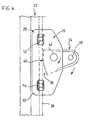
- FIG. 6is a side elevational view corresponding to FIG. 5 ;
- FIGS. 7 , 8 and 9are enlarged views of the portions of FIG. 6 that are correspondingly circled.
- FIG. 10is a sectional view on line A—A of FIG. 6 .
- the fall arrest safety device of the inventioncomprises a safety trolley and a “matching” rail.
- the trolleyis indicated by reference numeral 20 and best shown in FIGS. 1 to 4 .
- the railis shown in FIGS. 5 and 6 at 22 installed in a generally upright orientation on a ladder 23 that is intended to support a user of the safety device.
- the laddermay itself be incorporated in or mounted on a transmission tower or other structure on which the user is climbing or working. Alternatively, the rail may be mounted directly to the tower or other structure.
- FIG. 2shows the profile (cross-sectional) shape of the rail 22 in ghost outline and it will be seen that the profile includes a non-symmetrical profile portion 24 , which in this case is generally T-shaped but with one side of the top limb of the T thicker than the other side.
- the thicker sideis denoted 24 a in FIG. 2 and is shown at the bottom of the figure.
- the safety trolley 20has a body 26 which has an upper end 28 and a lower end 30 . As shown in FIG. 2 , the body is clearly marked with an arrow and the word “UP” to indicate proper orientation of the trolley on the rail.
- a passageway 32that has a profile shape complimentary to the shape of the non-symmetrical profile portion 24 of the rail 22 .
- the trolley 20can be installed only one way around on the rail. Assuming of course that the rail has bene correctly installed, the trolley 20 will fit on the rail only with its upper end 28 at the top.
- the trolleyincorporates a brake for frictionally engaging the rail 22 .
- the brakecomprises a so-called fall arrest lever 34 that is received in a recess 26 a in body 26 at the side remote from passageway 32 .
- the recesscommunicates with the passageway internally of the body and the lever has an inner end that includes a serrated braking surface 36 portion ( FIG. 4 ) for frictionally engaging an end face 38 of the rail 22 and arresting movement of the trolley 20 longitudinally of the rail.
- a serrated braking surface 36 portion( FIG. 4 ) for frictionally engaging an end face 38 of the rail 22 and arresting movement of the trolley 20 longitudinally of the rail.
- a plain and flat surface portion 40Immediately above the serrated surface portion 36 is a plain and flat surface portion 40 .
- lever 34is pivotally coupled to the trolley body 26 by a pivot pin 42 so that the lever can turn through a relatively small angular amount with respect to body 26 to bring either the plain surface portion 40 or the serrated portion 36 of the lever into contact with the rail 22 .
- lever 34has pivoted upwardly at its outer end so that the plain surface portion 40 of the lever is in contact with the rail. In this position of the lever, the trolley can slide longitudinally of the rail, but with some frictional resistance, i.e. the brake is essentially “off”. If the outer end of lever 34 is moved down, the serrated surface portion 36 engages and “bites” into the end face 38 of rail 22 . The brake is then “on”, and the trolley is locked to the rail.
- a coil spring 44is mounted on pivot pin 40 for biassing lever 34 downwardly at its outer end and into the “brake on” position, with the serrated surface portion 36 in engagement with rail 22 .
- lever 34is slotted or bifurcated and a so-called lanyard pin 46 is provided between the two bifurcated portions of the lever.
- One end portion 44 a of spring 44extends upwardly from pivot pin 42 and engages in a recess (not visible) in the body 26 of the trolley 20 .
- the other end 44 b of spring 44extends above and is curved slightly downwardly over lanyard pin 46 so as to in effect press down on the lanyard pin and bias lever 34 downwardly at its outer end.
- the brake of trolley 20is biassed “on” but can be released by lifting the outer end of lever 34 .
- FIG. 9shows a swivel hook 48 fitted to the lanyard pin 46 (the pin is removable for that purpose) and the swivel hook carries a latch or clip 50 that can be engaged with a safety belt or body harness worn by a user of the device.
- the harness and hook 50will be pulled upwardly with respect to the trolley 20 so that the brake is released and the trolley can move up on the rail 22 . Should the user slip or fall at this time, his or her weight will be exerted downwardly on the outer end of lever 34 , applying the brake.
- FIGS. 1 and 4show upper and lower rollers 52 and 54 that are incorporated into the body 26 of the trolley 20 and that are designed to run on the outer edge of the relevant side of the T-shaped portion of the rail profile. A similar pair of rollers is provided at the opposite side of the body but is not visible in the drawings.
- FIGS. 6 to 10illustrate the manner in which rail 22 is clamped to the ladder or other structure using clamping bolts (one of which is indicated at 56 in FIG. 10 ) positioned with their heads ( 58 ) in what is in effect an undercut channel extending longitudinally of the inner face of rail 22 (opposite the asymmetrical T-shaped portion 24 ).
- the inventionprovides a fall arrest safety device comprising a safety rail and brake trolley which are “matched” so that the trolley cannot be fitted to a safety rail up-side down and the device will always operate in the correct direction, assuming of course that the rail itself is correctly installed.
- the devicewill always “fail safe” in the sense that the weight of a user will tend to increase the braking force between the trolley and the rail.
- the usercan move up with respect to the rail simply by pulling up on the lever 34 .
- braking arrangementcould be used.
- a brake shoe or friction platecould engage the rail.
- the brakecould be actuated differently from the pivoted lever arrangement shown.
- the arrangement for releasing the brakecould be different.
Landscapes
- Health & Medical Sciences (AREA)
- General Health & Medical Sciences (AREA)
- Business, Economics & Management (AREA)
- Emergency Management (AREA)
- Engineering & Computer Science (AREA)
- Mechanical Engineering (AREA)
- Emergency Lowering Means (AREA)
Abstract
Description
Claims (3)
Applications Claiming Priority (3)
| Application Number | Priority Date | Filing Date | Title |
|---|---|---|---|
| CA2,325,699 | 2000-11-10 | ||
| CA002325699ACA2325699C (en) | 2000-11-10 | 2000-11-10 | Fall arrest safety device |
| PCT/CA2001/001560WO2002038222A1 (en) | 2000-11-10 | 2001-11-09 | Fall arrest safety device |
Related Parent Applications (1)
| Application Number | Title | Priority Date | Filing Date |
|---|---|---|---|
| PCT/CA2001/001560ContinuationWO2002038222A1 (en) | 2000-11-10 | 2001-11-09 | Fall arrest safety device |
Publications (2)
| Publication Number | Publication Date |
|---|---|
| US20030217887A1 US20030217887A1 (en) | 2003-11-27 |
| US6837337B2true US6837337B2 (en) | 2005-01-04 |
Family
ID=4167613
Family Applications (1)
| Application Number | Title | Priority Date | Filing Date |
|---|---|---|---|
| US10/435,706Expired - Fee RelatedUS6837337B2 (en) | 2000-11-10 | 2003-05-12 | Fall arrest safety device |
Country Status (4)
| Country | Link |
|---|---|
| US (1) | US6837337B2 (en) |
| AU (1) | AU2002214878A1 (en) |
| CA (1) | CA2325699C (en) |
| WO (1) | WO2002038222A1 (en) |
Cited By (30)
| Publication number | Priority date | Publication date | Assignee | Title |
|---|---|---|---|---|
| US20050059868A1 (en)* | 2003-07-09 | 2005-03-17 | Schurman Matthew J. | Method and apparatus for tissue oximetry |
| US20050082115A1 (en)* | 2003-10-20 | 2005-04-21 | Zedel | Fall arrest device with locking roller |
| US20050186648A1 (en)* | 2004-01-29 | 2005-08-25 | Schurman Matthew J. | OCT based method for diagnosis and therapy |
| US20060063988A1 (en)* | 2004-08-11 | 2006-03-23 | Schurman Matthew J | Method and apparatus for monitoring glucose levels in a biological tissue |
| US20060264719A1 (en)* | 2004-08-11 | 2006-11-23 | Schurman Matthew J | Method for data reduction and calibration of an OCT-based blood glucose monitor |
| US20060276696A1 (en)* | 2004-08-11 | 2006-12-07 | Glucolight Corporation | Methods for noninvasively measuring analyte levels in a subject |
| US20070193824A1 (en)* | 2006-02-16 | 2007-08-23 | Anderson Patrick K | Ladder safety apparatus |
| US20090015046A1 (en)* | 2007-07-13 | 2009-01-15 | Kids Ii, Inc. | Child seat liner |
| US20090275812A1 (en)* | 2008-03-04 | 2009-11-05 | Glucolight Corporation | Flowometry in Optical Coherence Tomography for Analyte Level Estimation |
| US20100012424A1 (en)* | 2006-10-16 | 2010-01-21 | Markus Krauss | Fall arrester for a climbing protection system |
| US20100326767A1 (en)* | 2010-09-01 | 2010-12-30 | Karl Guthrie | Swivel D-ring attachment point |
| US20100326768A1 (en)* | 2009-06-26 | 2010-12-30 | Verizon Patent And Licensing Inc. | Fall-arrest ladder system |
| US20110005861A1 (en)* | 2009-07-10 | 2011-01-13 | Transol Corporation | Fall arrest self rescuing trolley and system including the same |
| US7942242B1 (en) | 2007-05-14 | 2011-05-17 | O'connor Daniel J | Urban emergency escape method and system |
| US20110186382A1 (en)* | 2008-09-06 | 2011-08-04 | University Safety Systems Limited | Fall arrest device |
| EP2407210A1 (en) | 2010-06-16 | 2012-01-18 | Transol Corporation | Fall arrest self rescuing trolley and system including the same |
| US20120247869A1 (en)* | 2006-02-16 | 2012-10-04 | Anderson Patrick K | Ladder safety apparatus |
| US8413764B1 (en) | 2009-09-29 | 2013-04-09 | David A. Cohen | Ladder safety device, systems and methods of arresting falls from ladders |
| US8978821B2 (en) | 2009-07-10 | 2015-03-17 | Transol Corporation | Anchor trolley and fall arrest system and method implementing the same |
| US9320924B2 (en) | 2013-03-15 | 2016-04-26 | Honeywell International Inc. | Self-locking webbing connectable device attachment plate |
| US9784034B2 (en)* | 2013-03-18 | 2017-10-10 | Latchways Plc | Tether system for a safety line |
| US10047560B2 (en)* | 2014-05-29 | 2018-08-14 | Honeywell International Inc. | Guided type fall arrester—force control |
| WO2019018417A1 (en) | 2017-07-17 | 2019-01-24 | Safeworks, Llc | Climb assist and fall arrest system |
| US20210138280A1 (en)* | 2019-11-13 | 2021-05-13 | Shannon Stewart | Fall Arrest Assembly |
| AU2019203644B2 (en)* | 2017-07-24 | 2021-06-17 | Sayfa R&D Pty Ltd | A Vertical Fall Arrest Safety Device |
| US11052270B2 (en) | 2017-07-24 | 2021-07-06 | Sayfa R&D Pty Ltd | Vertical fall arrest safety device |
| USD947461S1 (en) | 2019-01-30 | 2022-03-29 | Sayfa R&D Pty Ltd | Vertical fall arrest safety device |
| US20220305345A1 (en)* | 2021-03-26 | 2022-09-29 | Walter Rafael Baumgartner Guillen | Rope holder apparatus and related system and method for use in sport climbing |
| US20230381556A1 (en)* | 2022-05-24 | 2023-11-30 | Honeywell International Inc. | Fall protection shuttle apparatus and methods of using the same |
| US12116843B2 (en) | 2017-07-17 | 2024-10-15 | Safeworks, Llc | Rope joining |
Families Citing this family (17)
| Publication number | Priority date | Publication date | Assignee | Title |
|---|---|---|---|---|
| US20080012370A1 (en)* | 2006-07-14 | 2008-01-17 | Brussard Associates, Inc. | Moveable strip door suspension system |
| US7393034B2 (en) | 2006-07-14 | 2008-07-01 | Brussard Associates, Inc. | Moveable strip door suspension system |
| US20100155176A1 (en)* | 2008-12-22 | 2010-06-24 | International Chimney Corporation | Ladder safety seat |
| DE102012204643A1 (en)* | 2012-03-22 | 2013-09-26 | Logaer Maschinenbau Gmbh | Steigsperrensystem for ladders |
| CN104225840A (en)* | 2014-09-17 | 2014-12-24 | 国网山东省电力公司泰安供电公司 | Anti-falling self-locking device |
| RU170149U1 (en)* | 2016-11-18 | 2017-04-17 | Роман Вячеславович Жуков | DEVICE FOR PREVENTING HUMAN FALLING WHEN LIFTING AND LIFTING ON THE SUPPORT OF ELECTRIC TRANSMISSION AIR LINES |
| CN107512687B (en)* | 2017-07-26 | 2023-02-28 | 上海和蕴机电科技有限公司 | Personnel safety detection device and detection method |
| RU180367U1 (en)* | 2017-11-28 | 2018-06-08 | Акционерное общество "Научно-технический центр Федеральной сетевой компании Единой энергетической системы" | Slider locking device for moving along a rigid anchor line |
| DE202018004216U1 (en)* | 2018-09-12 | 2018-11-26 | Meißner Sicherheitstechnik GmbH | platform |
| RU2708112C1 (en)* | 2018-12-11 | 2019-12-04 | Николай Сергеевич Руднев | Safety system for high-altitude works (version of t-beam guide rail) |
| CN110195567A (en)* | 2019-05-20 | 2019-09-03 | 保定天威保变电气股份有限公司 | A kind of transformer ladder and application method with guide rail |
| RU194851U1 (en)* | 2019-11-13 | 2019-12-25 | Владимир Михайлович Головин | Device for protecting a person from falling from a height |
| CN112717298B (en)* | 2021-01-07 | 2022-11-01 | 明阳智慧能源集团股份公司 | Climbing safety protection device of wind power tower cylinder and use method thereof |
| KR102824514B1 (en)* | 2024-10-07 | 2025-06-24 | 주식회사 더이로운 | Fall prevention apparatus installed on ladder |
| KR102824515B1 (en)* | 2024-10-10 | 2025-06-24 | 주식회사 더이로운 | Buffer type fall prevention apparatus installed on ladder |
| KR102825769B1 (en)* | 2024-10-21 | 2025-06-26 | 주식회사 더이로운 | Fall prevention apparatus installed on manhole |
| CN119424964A (en)* | 2024-12-06 | 2025-02-14 | 国网福建省电力有限公司宁德供电公司 | A portable tower anti-fall device |
Citations (11)
| Publication number | Priority date | Publication date | Assignee | Title |
|---|---|---|---|---|
| US3348632A (en)* | 1965-02-16 | 1967-10-24 | William E Swager | Climbing device |
| US3523591A (en)* | 1969-01-06 | 1970-08-11 | Cecil D Fountain | Climbing safety device |
| US4085818A (en)* | 1976-05-20 | 1978-04-25 | Swager William E | Plastic ladder and safety device |
| US4193475A (en)* | 1974-05-09 | 1980-03-18 | D B Industries, Inc. | Rigid rail safety device |
| US4269284A (en)* | 1978-09-25 | 1981-05-26 | Swager William E | Sliding clamp and adaptor |
| US4499966A (en)* | 1983-02-22 | 1985-02-19 | Tundra Holdings Ltd. | Emergency escape system |
| US5156240A (en) | 1991-05-31 | 1992-10-20 | Meyer Ostrobrod | Rope grab |
| US5238084A (en)* | 1992-03-05 | 1993-08-24 | Swager William E | Safety device for climbing ladders |
| US5265696A (en)* | 1992-01-31 | 1993-11-30 | D B Industries, Inc. | Ladder climbing safety clamp |
| US5271481A (en)* | 1991-11-20 | 1993-12-21 | Timothy Rich | Rolling restraint device |
| US6161647A (en)* | 1999-01-25 | 2000-12-19 | Pitt-Des Moines, Inc. | Fall arresting ladder safety device |
- 2000
- 2000-11-10CACA002325699Apatent/CA2325699C/ennot_activeExpired - Fee Related
- 2001
- 2001-11-09WOPCT/CA2001/001560patent/WO2002038222A1/ennot_activeApplication Discontinuation
- 2001-11-09AUAU2002214878Apatent/AU2002214878A1/ennot_activeAbandoned
- 2003
- 2003-05-12USUS10/435,706patent/US6837337B2/ennot_activeExpired - Fee Related
Patent Citations (11)
| Publication number | Priority date | Publication date | Assignee | Title |
|---|---|---|---|---|
| US3348632A (en)* | 1965-02-16 | 1967-10-24 | William E Swager | Climbing device |
| US3523591A (en)* | 1969-01-06 | 1970-08-11 | Cecil D Fountain | Climbing safety device |
| US4193475A (en)* | 1974-05-09 | 1980-03-18 | D B Industries, Inc. | Rigid rail safety device |
| US4085818A (en)* | 1976-05-20 | 1978-04-25 | Swager William E | Plastic ladder and safety device |
| US4269284A (en)* | 1978-09-25 | 1981-05-26 | Swager William E | Sliding clamp and adaptor |
| US4499966A (en)* | 1983-02-22 | 1985-02-19 | Tundra Holdings Ltd. | Emergency escape system |
| US5156240A (en) | 1991-05-31 | 1992-10-20 | Meyer Ostrobrod | Rope grab |
| US5271481A (en)* | 1991-11-20 | 1993-12-21 | Timothy Rich | Rolling restraint device |
| US5265696A (en)* | 1992-01-31 | 1993-11-30 | D B Industries, Inc. | Ladder climbing safety clamp |
| US5238084A (en)* | 1992-03-05 | 1993-08-24 | Swager William E | Safety device for climbing ladders |
| US6161647A (en)* | 1999-01-25 | 2000-12-19 | Pitt-Des Moines, Inc. | Fall arresting ladder safety device |
Cited By (67)
| Publication number | Priority date | Publication date | Assignee | Title |
|---|---|---|---|---|
| US7356365B2 (en) | 2003-07-09 | 2008-04-08 | Glucolight Corporation | Method and apparatus for tissue oximetry |
| US20050059868A1 (en)* | 2003-07-09 | 2005-03-17 | Schurman Matthew J. | Method and apparatus for tissue oximetry |
| US20050082115A1 (en)* | 2003-10-20 | 2005-04-21 | Zedel | Fall arrest device with locking roller |
| US7137481B2 (en)* | 2003-10-20 | 2006-11-21 | Zedel | Fall arrest device with locking roller |
| US20050186648A1 (en)* | 2004-01-29 | 2005-08-25 | Schurman Matthew J. | OCT based method for diagnosis and therapy |
| US7510849B2 (en) | 2004-01-29 | 2009-03-31 | Glucolight Corporation | OCT based method for diagnosis and therapy |
| US9078560B2 (en) | 2004-08-11 | 2015-07-14 | Glt Acquisition Corp. | Method for data reduction and calibration of an OCT-based physiological monitor |
| US20060063988A1 (en)* | 2004-08-11 | 2006-03-23 | Schurman Matthew J | Method and apparatus for monitoring glucose levels in a biological tissue |
| US8306596B2 (en) | 2004-08-11 | 2012-11-06 | Glt Acquisition Corp. | Method for data reduction and calibration of an OCT-based physiological monitor |
| US20060276696A1 (en)* | 2004-08-11 | 2006-12-07 | Glucolight Corporation | Methods for noninvasively measuring analyte levels in a subject |
| US9554737B2 (en) | 2004-08-11 | 2017-01-31 | Masimo Corporation | Noninvasively measuring analyte levels in a subject |
| US20060264719A1 (en)* | 2004-08-11 | 2006-11-23 | Schurman Matthew J | Method for data reduction and calibration of an OCT-based blood glucose monitor |
| US9668679B2 (en) | 2004-08-11 | 2017-06-06 | Masimo Corporation | Method for data reduction and calibration of an OCT-based physiological monitor |
| US8204566B2 (en) | 2004-08-11 | 2012-06-19 | Glt Acquisition Corp. | Method and apparatus for monitoring blood constituent levels in biological tissue |
| US10791971B2 (en) | 2004-08-11 | 2020-10-06 | Masimo Corporation | Method for data reduction and calibration of an OCT-based physiological monitor |
| US7822452B2 (en) | 2004-08-11 | 2010-10-26 | Glt Acquisition Corp. | Method for data reduction and calibration of an OCT-based blood glucose monitor |
| US10130291B2 (en) | 2004-08-11 | 2018-11-20 | Masimo Corporation | Method for data reduction and calibration of an OCT-based physiological monitor |
| US7254429B2 (en) | 2004-08-11 | 2007-08-07 | Glucolight Corporation | Method and apparatus for monitoring glucose levels in a biological tissue |
| US11426104B2 (en) | 2004-08-11 | 2022-08-30 | Masimo Corporation | Method for data reduction and calibration of an OCT-based physiological monitor |
| US20110015505A1 (en)* | 2004-08-11 | 2011-01-20 | GLT Acquistition Corp. | Method for data reduction and calibration of an oct-based physiological monitor |
| US8548549B2 (en) | 2004-08-11 | 2013-10-01 | Glt Acquisition Corp. | Methods for noninvasively measuring analyte levels in a subject |
| US8788003B2 (en) | 2004-08-11 | 2014-07-22 | Glt Acquisition Corp. | Monitoring blood constituent levels in biological tissue |
| US8036727B2 (en) | 2004-08-11 | 2011-10-11 | Glt Acquisition Corp. | Methods for noninvasively measuring analyte levels in a subject |
| US20120247869A1 (en)* | 2006-02-16 | 2012-10-04 | Anderson Patrick K | Ladder safety apparatus |
| US20070193824A1 (en)* | 2006-02-16 | 2007-08-23 | Anderson Patrick K | Ladder safety apparatus |
| US8584797B2 (en)* | 2006-10-16 | 2013-11-19 | Honeywell Fall Protection Deutschland Gmbh & Co. Kg | Fall arrester for a climbing protection system |
| US20100012424A1 (en)* | 2006-10-16 | 2010-01-21 | Markus Krauss | Fall arrester for a climbing protection system |
| US7942242B1 (en) | 2007-05-14 | 2011-05-17 | O'connor Daniel J | Urban emergency escape method and system |
| US20090015046A1 (en)* | 2007-07-13 | 2009-01-15 | Kids Ii, Inc. | Child seat liner |
| US8042869B2 (en) | 2007-07-13 | 2011-10-25 | Kids Ii, Inc. | Child seat liner |
| US11033210B2 (en) | 2008-03-04 | 2021-06-15 | Masimo Corporation | Multispot monitoring for use in optical coherence tomography |
| US10368787B2 (en) | 2008-03-04 | 2019-08-06 | Masimo Corporation | Flowometry in optical coherence tomography for analyte level estimation |
| US11426105B2 (en) | 2008-03-04 | 2022-08-30 | Masimo Corporation | Flowometry in optical coherence tomography for analyte level estimation |
| US8571617B2 (en) | 2008-03-04 | 2013-10-29 | Glt Acquisition Corp. | Flowometry in optical coherence tomography for analyte level estimation |
| US8768423B2 (en) | 2008-03-04 | 2014-07-01 | Glt Acquisition Corp. | Multispot monitoring for use in optical coherence tomography |
| US11660028B2 (en) | 2008-03-04 | 2023-05-30 | Masimo Corporation | Multispot monitoring for use in optical coherence tomography |
| US9833180B2 (en) | 2008-03-04 | 2017-12-05 | Masimo Corporation | Multispot monitoring for use in optical coherence tomography |
| US9060721B2 (en) | 2008-03-04 | 2015-06-23 | Glt Acquisition Corp. | Flowometry in optical coherence tomography for analyte level estimation |
| US20100113900A1 (en)* | 2008-03-04 | 2010-05-06 | Glucolight Corporation | Multispot Monitoring for Use in Optical Coherence Tomography |
| US20090275812A1 (en)* | 2008-03-04 | 2009-11-05 | Glucolight Corporation | Flowometry in Optical Coherence Tomography for Analyte Level Estimation |
| US20110186382A1 (en)* | 2008-09-06 | 2011-08-04 | University Safety Systems Limited | Fall arrest device |
| US20100326768A1 (en)* | 2009-06-26 | 2010-12-30 | Verizon Patent And Licensing Inc. | Fall-arrest ladder system |
| US8348014B2 (en)* | 2009-06-26 | 2013-01-08 | Verizon Patent And Licensing Inc. | Fall-arrest ladder system |
| US20110005861A1 (en)* | 2009-07-10 | 2011-01-13 | Transol Corporation | Fall arrest self rescuing trolley and system including the same |
| US8978821B2 (en) | 2009-07-10 | 2015-03-17 | Transol Corporation | Anchor trolley and fall arrest system and method implementing the same |
| US9901759B2 (en) | 2009-07-10 | 2018-02-27 | Transol Corporation | Anchor trolley and fall arrest system and method implementing the same |
| US8316990B2 (en) | 2009-07-10 | 2012-11-27 | Transol Corporation | Fall arrest self rescuing trolley and system including the same |
| US10617897B2 (en) | 2009-07-10 | 2020-04-14 | Transol Coporation | Anchor trolley and fall arrest system and method implementing the same |
| US8413764B1 (en) | 2009-09-29 | 2013-04-09 | David A. Cohen | Ladder safety device, systems and methods of arresting falls from ladders |
| EP2407210A1 (en) | 2010-06-16 | 2012-01-18 | Transol Corporation | Fall arrest self rescuing trolley and system including the same |
| US8973705B2 (en)* | 2010-09-01 | 2015-03-10 | Climb Tech, Llc | Swivel D-ring attachment point |
| US20100326767A1 (en)* | 2010-09-01 | 2010-12-30 | Karl Guthrie | Swivel D-ring attachment point |
| US9248324B1 (en) | 2010-09-01 | 2016-02-02 | Climb Tech, Llc | Swivel D-ring attachment point |
| US9320924B2 (en) | 2013-03-15 | 2016-04-26 | Honeywell International Inc. | Self-locking webbing connectable device attachment plate |
| US9784034B2 (en)* | 2013-03-18 | 2017-10-10 | Latchways Plc | Tether system for a safety line |
| US10370898B2 (en) | 2013-03-18 | 2019-08-06 | Latchways Plc | Tether system for a safety line |
| US10047560B2 (en)* | 2014-05-29 | 2018-08-14 | Honeywell International Inc. | Guided type fall arrester—force control |
| WO2019018417A1 (en) | 2017-07-17 | 2019-01-24 | Safeworks, Llc | Climb assist and fall arrest system |
| US12116843B2 (en) | 2017-07-17 | 2024-10-15 | Safeworks, Llc | Rope joining |
| US11052270B2 (en) | 2017-07-24 | 2021-07-06 | Sayfa R&D Pty Ltd | Vertical fall arrest safety device |
| US11091957B2 (en) | 2017-07-24 | 2021-08-17 | Sayfa R&D Pty Ltd | Modular ladder system |
| AU2019203644B2 (en)* | 2017-07-24 | 2021-06-17 | Sayfa R&D Pty Ltd | A Vertical Fall Arrest Safety Device |
| USD947461S1 (en) | 2019-01-30 | 2022-03-29 | Sayfa R&D Pty Ltd | Vertical fall arrest safety device |
| US20210138280A1 (en)* | 2019-11-13 | 2021-05-13 | Shannon Stewart | Fall Arrest Assembly |
| US20220305345A1 (en)* | 2021-03-26 | 2022-09-29 | Walter Rafael Baumgartner Guillen | Rope holder apparatus and related system and method for use in sport climbing |
| US20230381556A1 (en)* | 2022-05-24 | 2023-11-30 | Honeywell International Inc. | Fall protection shuttle apparatus and methods of using the same |
| US12415101B2 (en)* | 2022-05-24 | 2025-09-16 | Honeywell Safety Products Usa, Inc. | Fall protection shuttle apparatus and methods of using the same |
Also Published As
| Publication number | Publication date |
|---|---|
| WO2002038222A1 (en) | 2002-05-16 |
| CA2325699A1 (en) | 2002-05-10 |
| AU2002214878A1 (en) | 2002-05-21 |
| US20030217887A1 (en) | 2003-11-27 |
| CA2325699C (en) | 2009-10-20 |
Similar Documents
| Publication | Publication Date | Title |
|---|---|---|
| US6837337B2 (en) | Fall arrest safety device | |
| US8348016B2 (en) | Descender with fall arrest and controlled rate of descent | |
| EP1680192B1 (en) | Fall arrest device and system incorporating the same | |
| US7111707B2 (en) | Sliding anchorage device | |
| US7137481B2 (en) | Fall arrest device with locking roller | |
| US8316990B2 (en) | Fall arrest self rescuing trolley and system including the same | |
| US11136823B1 (en) | Ladder fall protection system and fall arrester | |
| US20110232995A1 (en) | Roping devices | |
| US9168421B2 (en) | Fall protection device for use in climbing poles | |
| US10619417B2 (en) | Pass-through cable grab system | |
| US20050189171A1 (en) | Safety system and method of use for high workers | |
| EP2536913B1 (en) | A system for the protection of individuals who use ladders | |
| US9956436B2 (en) | Rope access equipment | |
| US12115395B2 (en) | Controlled descender and/or ascender device | |
| US20030183449A1 (en) | Fall arresting hook for use on ladders | |
| US20090178886A1 (en) | Ladder stabilizer | |
| CA2943729C (en) | Fall arrester and ladder fall prevention system | |
| RU59987U1 (en) | LIFE RESCUE DEVICE | |
| GB2450725A (en) | A roof ladder with a fall arrest system | |
| WO2024118200A1 (en) | Controlled descender and/or ascender device | |
| AU2005223872A1 (en) | Improved roping device | |
| WO2009063183A1 (en) | Improved safety devices | |
| GB2408286A (en) | Bracket for ladder safety rope | |
| EP2407210A1 (en) | Fall arrest self rescuing trolley and system including the same | |
| CA2484767A1 (en) | High-rise emergency escape device |
Legal Events
| Date | Code | Title | Description |
|---|---|---|---|
| AS | Assignment | Owner name:RADIAN COMMUNICATION SERVICES (CANADA) LIMITED, CA Free format text:ASSIGNMENT OF ASSIGNORS INTEREST;ASSIGNORS:THOMAS, DAVID ALAN;WAHBA, YOHANNA;REEL/FRAME:014355/0429 Effective date:20030721 | |
| FPAY | Fee payment | Year of fee payment:4 | |
| AS | Assignment | Owner name:CANADIAN IMPERIAL BANK OF COMMERCE, ONTARIO Free format text:SECURITY AGREEMENT;ASSIGNOR:PRESTIGE TELECOMMUNICATIONS INC.;REEL/FRAME:026436/0226 Effective date:20081215 | |
| FPAY | Fee payment | Year of fee payment:8 | |
| AS | Assignment | Owner name:BANK OF NOVA SCOTIA, THE, CANADA Free format text:SECURITY AGREEMENT;ASSIGNOR:7922825 CANADA INC.;REEL/FRAME:033783/0626 Effective date:20140916 | |
| AS | Assignment | Owner name:7922825 CANADA INC., CANADA Free format text:RELEASE OF SECURITY INTEREST IN PATENTS;ASSIGNOR:THE BANK OF NOVA SCOTIA;REEL/FRAME:036395/0417 Effective date:20150814 | |
| REMI | Maintenance fee reminder mailed | ||
| LAPS | Lapse for failure to pay maintenance fees | ||
| STCH | Information on status: patent discontinuation | Free format text:PATENT EXPIRED DUE TO NONPAYMENT OF MAINTENANCE FEES UNDER 37 CFR 1.362 | |
| FP | Lapsed due to failure to pay maintenance fee | Effective date:20170104 |