US6836546B1 - Apparatus and method of coupling home network signals between an analog phone line and a digital bus - Google Patents
Apparatus and method of coupling home network signals between an analog phone line and a digital busDownload PDFInfo
- Publication number
- US6836546B1 US6836546B1US09/495,122US49512200AUS6836546B1US 6836546 B1US6836546 B1US 6836546B1US 49512200 AUS49512200 AUS 49512200AUS 6836546 B1US6836546 B1US 6836546B1
- Authority
- US
- United States
- Prior art keywords
- wire
- network
- isdn
- bus
- path
- Prior art date
- Legal status (The legal status is an assumption and is not a legal conclusion. Google has not performed a legal analysis and makes no representation as to the accuracy of the status listed.)
- Expired - Fee Related
Links
Images


Classifications
- H—ELECTRICITY
- H04—ELECTRIC COMMUNICATION TECHNIQUE
- H04L—TRANSMISSION OF DIGITAL INFORMATION, e.g. TELEGRAPHIC COMMUNICATION
- H04L12/00—Data switching networks
- H04L12/02—Details
- H—ELECTRICITY
- H04—ELECTRIC COMMUNICATION TECHNIQUE
- H04M—TELEPHONIC COMMUNICATION
- H04M3/00—Automatic or semi-automatic exchanges
- H04M3/005—Interface circuits for subscriber lines
Definitions
- the present inventionrelates to network interfacing, and more particularly to methods and systems for controlling transmission of data between network stations connected to a telephone line medium.
- Local area networksuse a network cable or other media to link stations on the network.
- Each local area network architectureuses a media access control (MAC) enabling network interface cards at each station to share access to the media.
- MACmedia access control
- a home network environmentprovides the advantage that existing telephone wiring in a home may be used to implement a home network environment.
- telephone linesare inherently noisy due to spurious noise caused by electrical devices in the home, for example dimmer switches, transformers of home appliances, etc.
- the twisted pair telephone linessuffer from turn-on transients due to on-hook and off-hook and noise pulses from the standard POTS telephones, and electrical systems such as heating and air-conditioning systems, etc.
- An additional problem in telephone wiring networksis that the signal condition (i.e., shape) of a transmitted waveform depends largely on the wiring topology. Numerous branch connections in the twisted pair telephone line medium, as well as the different associated lengths of the branch connections, may cause multiple signal reflections on a transmitted network signal. Telephone wiring topology may cause the network signal from one network station to have a peak to peak voltage on the order of 10 to 20 millivolts, whereas network signals from another network station may have a value on the order of one to two volts. Hence, the amplitude and shape of a received pulse may be so distorted that recovery of a transmitted clock or transmit data from the received pulse becomes substantially difficult.
- NTBAnetwork termination basic access
- ISDNIntegrated Services Digital Network
- NTBA devicesmap a two wire ISDN signal from a central office into a four wire S0 bus having a two wire send path and a two wire receive path for sending and receiving the ISDN-based signals throughout a customer premises.
- the ISDN-based signalsgenerate harmonic reflections on the S0 bus that cause substantial interference with the higher-frequency network signals.
- the zero crossing of an ISDN-based signalinterferes substantially with the transmitted network signals, rendering the transmitted network signal unusable due to the harsh conditions on the four wire S0 bus.
- PBXprivate branch exchanges
- NTBA devicesthere are newer private branch exchanges (PBX) that include an internal four wire S0 bus and up to eight two-wire (e.g., tip and ring) analog connectors for analog telephones.
- PBX devicesprovide the flexibility of both a digital S0 bus and analog telephone lines, there is no capability for enabling coupling of home network signals between an end station connected to an analog telephone line, and another end station connected to the digital S0 bus.
- NTBAnetwork termination basic access
- filtersare coupled between each ISDN device and the four-wire S0 bus, insuring that the four-wire S0 bus is isolated from capacitive influences of the ISDN devices.
- a high pass filtercouples analog telephone lines to the S0 bus to enable transmission of home network signals between two-wire analog phone lines and to the four-wire digital S0 bus.
- One aspect of the present inventionprovides a method of implementing a local area network in a home telephone network having a connector, configured for sending and receiving ISDN-based signals to and from a public switched telephone network, and a four-wire bus.
- the four-wire busincludes a two-wire send path and a two-wire receive path for sending and receiving the ISDN-based signals, respectively, between the connector and connected ISDN terminal devices.
- the methodincludes connecting a high pass filter between the four-wire bus and a two-wire analog telephone line configured for transmitting analog telephone signals, and transmitting network data signals between a first network node coupled to the four wire bus and a second network node coupled to the two-wire analog telephone line.
- Connection of the high pass filter between the four-wire bus and the two-wire analog telephone lineenables the high frequency network data signals to be transmitted between the four-wire bus and the two-wire analog telephone line, without interference of telephone signals on the respective two-wire bus and two-wire analog telephone line.
- a particular feature of this aspectincludes isolating capacitive influences of each of the connected ISDN terminal devices from the t-two-wire send path.
- the isolation of capacitive influences of each of the connected ISDN terminal devicesinsures that the circuitry within the ISDN terminal devices do not induce any capacitive loads onto the two-wire send path that may adversely affect transmission of the home network signals.
- the computer networkincludes a connector configured for sending and receiving ISDN-based signals to and from a public switched telephone network.
- the computer networkalso includes a four-wire bus having a two-wire send path and a two-wire receive path for sending and receiving the ISDN-based signals between the connector and ISDN terminal devices.
- a low pass filtercoupled between the two-wire send path and the connector, is configured for isolating capacitive influences of the connector from the two-wire send path and filtering ISDN harmonic signals occurring substantially at the frequencies of network data signals.
- the computer networkalso includes ISDN terminal filters, each configured for isolating capacitive influences of a corresponding one of the ISDN terminal devices from the two-wire send path, and first and second end stations configured for exchanging the network data signals at frequencies substantially higher than the ISDN-based signals via at least one of the two-wire send path and the two-wire receive path, wherein the first end station is coupled to at least one of the two-wire send path and the two-wire receive path and the second end station is coupled to an analog telephone line.
- the computer networkalso includes a high pass filter for coupling the four-wire bus to the analog telephone line, enabling the second end station to exchange the network data signals via the analog telephone line and the four-wire bus.
- FIG. 1is a block diagram illustrating a computer network implemented in a customer premises having ISDN-based wiring according to an embodiment of the present invention.
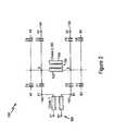
- FIG. 2is a diagram illustrating in detail the high pass filter of FIG. 1 according to an embodiment of the present invention.
- FIG. 3is a diagram illustrating another computer network implemented in a customer premises having a PBX system according to an embodiment of the present invention.
- the disclosed embodimentprovides a high pass coupling filter configured for coupling home network signals between analog phone lines and an S0 bus in an ISDN-based customer premises networking system.
- a descriptionwill first be provided of the ISDN-based customer premises networking system, followed by a detailed description of the high pass coupling filter.
- FIG. 1is a block diagram illustrating an Ethernet (IEEE 802.3) local area network 10 implemented in a home environment using ISDN-based signals according to an embodiment of the present invention.
- the home environmentincludes a network termination basic access (NTBA) device 12 , configured for sending and receiving Integrated Services Digital Network (ISDN) signals to and from a public switched telephone network via a two-wire twisted pair:
- the NTBA device 12is configured for outputting ISDN signals onto a four-wire S0 bus 14 , having two wires for a send path 16 and two wires for a receive path 18 .
- the S0 bus fourteenmay have multiple connections, or “taps” 20 connected in parallel off the S0 bus 14 .
- the S0 busmay be internal to a PBX system; as such, the NTBA 12 serves as a connector for the S0 bus 14 to the two-wire twisted pair from the public switched telephone network.
- the NTBA 12maps the ISDN signals into a two-wire send path 16 , and a two-wire receive path 18 .
- the receive path 18reflects the ISDN signal transmitted on the send path 16 , with a 2-bit spacing relative to the ISDN clock frequency of about 200 kHz (e.g., 192 kHz).
- home PNAdue to the high level of ISDN noise in the frequency used for home networking, referred to as home PNA by the Home Phone Network Alliance, transmissions of home PNA data on the ISDN S0 bus 14 is normally not possible.
- a low pass filter 30is installed in the send path 16 of the NTBA 12 .
- the low pass filter 30is illustrated as external to the NTBA 12 , although the low pass filter 30 may also be integrated internally within the NTBA 12 ; in either case, the low pass filter 30 will be coupled to the output terminal of the NTBA device 12 , either internally or externally.
- the low pass filter 30includes an inductor 32 (e.g., 2 ⁇ 4.7 millihenries) and a capacitor 34 (e.g., 1 nanofarad) that attenuates the high frequency noise caused by the harmonics of the 192 kHz ISDN signal.
- the send path 16 and receive path 18are free of high frequency harmonics that may affect die home network signals between end stations 22 a and 22 b .
- the inductor 32implemented for example as a common mode choke, isolates capacitive influences of the NTBA 12 from the two-wire send path 16 , enabling the high frequency home network signals to be transmitted without capacitive loading by the NTBA 12 .
- the disclosed network 10also includes ISDN terminal filters 62 configured for isolating capacitive influences of each of the connected ISDN terminal devices 60 from the two-wire send path 16 .
- Each ISDN terminal filter 62is preferably implemented as a common mode choke (e.g., 2 ⁇ 4.7 millihenries) which is connected between the corresponding ISDN terminal device 60 and the two wire send path 16 .
- the low pass filter 30 and the ISDN terminal filters 62isolate capacitive influences of the respective ISDN devices from the two-wire send path 16 , providing optimal conditions for transmission of the home network signals having a frequency of at least about 7.5 MHz.
- each end station 22is coupled to a pair of commercially-available S0 transformers 64 , for example from Vogt Electronic AG of Erlau, Germany.
- the 4-wire tap 20 a of end station 22 ais coupled to the ends of the primary windings of transformers 64 a and 64 b .
- the 4-wire tap 20 bcouples the analog telephone line 100 , described below, to the end of the primary windings of transformers 64 c and 64 d .
- the secondary windings of transformers 64 a , 64 b , 64 c , and 64 dare not used.
- Each primary windingincludes a middle tap 66 , coupled substantially in the middle (i.e., substantially the center) of the corresponding primary winding.
- the ends of transformers 64 a and 64 bare symmetrically connected to the two wires a 1 , b 1 of the send direction 16 and the two wires a 2 , b 2 of the S0 bus 14 , respectively.
- the ends of transformers 64 c and 64 dare symmetrically connected to the two wires a 1 , b 1 of the send direction 16 and the two wires a 2 , b 2 of the S0 bus 14 , respectively.
- Each end station 22outputs the home network signal as a two-wire signal (i.e., a differential signal pair) on two-wire signal lines 68 ; hence the end station 22 a sends and receives the differential home network signals on signal lines 68 a and 68 b , and the end stations having two-wire analog telephone lines 100 and coupled to the high pass filter 130 (e.g., end station 22 b) send and receive the differential home network signals on the signal lines 68 c and 68 d.
- a two-wire signali.e., a differential signal pair
- the signal lines 68 a , 68 b , and 68 c , and 68 dare coupled to the middle taps 66 a , 66 b , 66 c , and 66 d , respectively, enabling the two-wire home network signal to be transferred across the four-wire S0 bus 14 .
- the end station 22outputs a first home network signal to the middle tap 66 a of the primary winding 64 a coupled to the send path 16 , and a second home network signal complementary to the first home network signal (i.e., the corresponding differential signal), to the middle tap 66 b of the primary winding 64 b coupled to the receive path 18 .
- the end station 22 breceives the first home network signal from the send path 16 , and the second home network signal from the receive path 18 , resulting in substantially improved reception of the home network signal by optimizing of the loop resistance of the bus 14 .
- Experimental testing of the disclosed arrangementhas resulted in successful reception of 7.5 MHz home network signals on an S0 bus 14 where the end stations 22 transmit the home network signals across a distance of about 80 meters.
- the high pass filter 130couples signal lines 68 c and 68 d to the analog two-wire telephone lines 100 , enabling the end station 22 b to send home network signals to the end station 22 a via the four-wire S0 bus 14 .
- the high pass filter 130rejects the lower frequency ISDN and analog telephone signals, ensuring that there is no interference between the digital signals of the four-wire bus 14 and the analog signals of the two-wire telephone line 100 .
- FIG. 2is a block diagram illustrating in detail the high pass filter 130 according to an embodiment of the present invention.
- the high pass filter 130includes connectors 140 , 142 , 144 , and 146 for connecting the signal lines 68 d , 68 c and the two-wire analog lines 100 at terminal ends A 1 , B 1 , A 2 , and B 2 , respectively.
- the connectors 140 and 142establish a high pass filter across signal lines 68 c and 68 d
- connectors 144 and 146establish a high pass filter across the two-wire analog lines 100 .
- a high pass filteris formed across the connections A 1 and B 1 based on the capacitors C 1 and C 2 , and the inductance element 150 , shown as a choke.
- the choke 150includes a first winding 152 coupled to nodes A and B.
- the nodes A and B of high pass filter 130are capacitively coupled to a corresponding one of the telephone lines 100 for each twisted pair.
- the node Ais capacitively coupled to terminal connections A 1 , A 2 , A 3 , . . . A 7 and node B is capacitively coupled to connections and B 1 , B 2 , B 3 , . . . B 7 .
- the first winding 152provides an inductive load across all the associated twisted pair telephone wires 100 resulting in connection of the twisted pair wires for transmission of network data signals.
- the choke 150also includes a second winding 154 that is galvanically isolated from the first winding. Since the second winding 154 is inductively coupled to the first winding 152 via the core 156 , the inductive coupling generates a copy of the transmitted network data signals onto the second winding 154 . Hence, the terminal ends of the second winding 154 may be used for additional monitoring of the transmit network data signals passing through the first winding 152 without adding any additional distortion to the network medium.
- the capacitance between terminals A and Bmaybe substantially high as to cause a short-circuit for high frequency signals between the two nodes.
- the high pass filter circuit 130also includes a second high inductance device 160 , labeled as choke 1 , which is inserted between the terminal ends 140 and 142 and the actual terminal connections A 1 and B 1 of lines 64 d and 64 c .
- the high inductance device 160compensates for the high capacitance, limiting the possibility of a short-circuit or loss in performance for the high frequency network signals.
- FIG. 3is a diagram illustrating an alternative implementation of the local area network 10 of FIG. 1 according to another embodiment of the present invention.
- the network 200includes a private branch exchange (PBX) 210 .
- the PBX 210includes an internal connector 212 for an internal S0 bus 214 having a send path 216 and a receive path 218 .
- the internal connector 212has circuitry that is configured for connecting the internal S0 bus 214 to the S0 bus 14 (also referred to as the external S0 bus) for communication with the public switched telephone network.
- the PBX 210will typically have four to eight analog (tip-and-ring) connectors (not shown), one external connector for connection to the external S0 bus, and up to eight digital connections off the internal S0 bus 214 .
- the local area network 10includes the same filters 30 and 62 described above with respect to 111 FIG. 1, and also includes taps 220 connected in parallel off the internal S0 bus 214 for connection to an ISDN terminal device 60 , a home network end station 22 a coupled to the internal S0 bus 214 , or an end station 22 b coupled to the internal S0 bus 214 via two-wire analog telephone lines 100 and the high pass coupling filter 130 .
- the features of providing a high pass coupling filter 130 between analog phone lines and an S0 busmay also be applied to a PBX system 210 .
- the filter 30is illustrated as external to the PBX 210 , the filter 30 may also be integrated within the PBX 210 .
- a high pass filteris added between the four-wire bus and a two-wire analog telephone line, enabling network data signals to be transmitted between a first network node coupled to the four wire bus and a second network node coupled to the two-wire analog telephone line.
- home networking technologiesmay be implemented in residential premises, regardless of whether the end station is connected to an analog telephone line or the four-wire bus.
Landscapes
- Engineering & Computer Science (AREA)
- Signal Processing (AREA)
- Computer Networks & Wireless Communication (AREA)
- Telephonic Communication Services (AREA)
- Small-Scale Networks (AREA)
- Communication Control (AREA)
- Financial Or Insurance-Related Operations Such As Payment And Settlement (AREA)
- Facsimile Transmission Control (AREA)
- Selective Calling Equipment (AREA)
Abstract
Description
Claims (12)
Priority Applications (10)
| Application Number | Priority Date | Filing Date | Title |
|---|---|---|---|
| US09/495,122US6836546B1 (en) | 1999-11-03 | 2000-02-01 | Apparatus and method of coupling home network signals between an analog phone line and a digital bus |
| AT00959923TATE322793T1 (en) | 1999-11-03 | 2000-09-05 | DEVICE AND METHOD FOR TRANSMITTING DATA OVER A DOMESTIC TELEPHONE NETWORK |
| AU71160/00AAU7116000A (en) | 1999-11-03 | 2000-09-05 | Apparatus and method of coupling home network signals between an analog phone line and a digital bus |
| JP2001534847AJP2003513548A (en) | 1999-11-03 | 2000-09-05 | Apparatus and method for coupling home network signals between an analog telephone line and a digital bus |
| EP00959923AEP1226705B1 (en) | 1999-11-03 | 2000-09-05 | Apparatus and method for transmitting data over a home telephone network |
| DE60027191TDE60027191T2 (en) | 1999-11-03 | 2000-09-05 | DEVICE AND METHOD FOR TRANSFERRING DATA OVER A TELEPHONE NETWORK |
| KR1020027005774AKR100682642B1 (en) | 1999-11-03 | 2000-09-05 | Apparatus and method for coupling home network signals between analog telephone lines and digital buses |
| PCT/US2000/024396WO2001033820A1 (en) | 1999-11-03 | 2000-09-05 | Apparatus and method of coupling home network signals between an analog phone line and a digital bus |
| CNB008132194ACN1175650C (en) | 1999-11-03 | 2000-09-05 | Apparatus and method for coupling home network signal between analog telephone line and digital bus |
| TW089119302ATW498652B (en) | 1999-11-03 | 2000-09-20 | Apparatus and method of coupling home network signals between an analog phone line and a digital bus |
Applications Claiming Priority (2)
| Application Number | Priority Date | Filing Date | Title |
|---|---|---|---|
| US16324099P | 1999-11-03 | 1999-11-03 | |
| US09/495,122US6836546B1 (en) | 1999-11-03 | 2000-02-01 | Apparatus and method of coupling home network signals between an analog phone line and a digital bus |
Publications (1)
| Publication Number | Publication Date |
|---|---|
| US6836546B1true US6836546B1 (en) | 2004-12-28 |
Family
ID=26859471
Family Applications (1)
| Application Number | Title | Priority Date | Filing Date |
|---|---|---|---|
| US09/495,122Expired - Fee RelatedUS6836546B1 (en) | 1999-11-03 | 2000-02-01 | Apparatus and method of coupling home network signals between an analog phone line and a digital bus |
Country Status (10)
| Country | Link |
|---|---|
| US (1) | US6836546B1 (en) |
| EP (1) | EP1226705B1 (en) |
| JP (1) | JP2003513548A (en) |
| KR (1) | KR100682642B1 (en) |
| CN (1) | CN1175650C (en) |
| AT (1) | ATE322793T1 (en) |
| AU (1) | AU7116000A (en) |
| DE (1) | DE60027191T2 (en) |
| TW (1) | TW498652B (en) |
| WO (1) | WO2001033820A1 (en) |
Cited By (25)
| Publication number | Priority date | Publication date | Assignee | Title |
|---|---|---|---|---|
| US7197028B2 (en) | 2000-04-18 | 2007-03-27 | Serconet Ltd. | Telephone communication system over a single telephone line |
| US7317793B2 (en) | 2003-01-30 | 2008-01-08 | Serconet Ltd | Method and system for providing DC power on local telephone lines |
| US7436842B2 (en) | 2001-10-11 | 2008-10-14 | Serconet Ltd. | Outlet with analog signal adapter, a method for use thereof and a network using said outlet |
| US7483524B2 (en) | 1999-07-20 | 2009-01-27 | Serconet, Ltd | Network for telephony and data communication |
| US7522714B2 (en) | 2000-03-20 | 2009-04-21 | Serconet Ltd. | Telephone outlet for implementing a local area network over telephone lines and a local area network using such outlets |
| US7542554B2 (en) | 2001-07-05 | 2009-06-02 | Serconet, Ltd | Telephone outlet with packet telephony adapter, and a network using same |
| US7587001B2 (en) | 2006-01-11 | 2009-09-08 | Serconet Ltd. | Apparatus and method for frequency shifting of a wireless signal and systems using frequency shifting |
| US7633966B2 (en) | 2000-04-19 | 2009-12-15 | Mosaid Technologies Incorporated | Network combining wired and non-wired segments |
| US7636361B1 (en)* | 2005-09-27 | 2009-12-22 | Sun Microsystems, Inc. | Apparatus and method for high-throughput asynchronous communication with flow control |
| US7656904B2 (en) | 2003-03-13 | 2010-02-02 | Mosaid Technologies Incorporated | Telephone system having multiple distinct sources and accessories therefor |
| US7686653B2 (en) | 2003-09-07 | 2010-03-30 | Mosaid Technologies Incorporated | Modular outlet |
| US7873058B2 (en) | 2004-11-08 | 2011-01-18 | Mosaid Technologies Incorporated | Outlet with analog signal adapter, a method for use thereof and a network using said outlet |
| US8175649B2 (en) | 2008-06-20 | 2012-05-08 | Corning Mobileaccess Ltd | Method and system for real time control of an active antenna over a distributed antenna system |
| US8270430B2 (en) | 1998-07-28 | 2012-09-18 | Mosaid Technologies Incorporated | Local area network of serial intelligent cells |
| US8325759B2 (en) | 2004-05-06 | 2012-12-04 | Corning Mobileaccess Ltd | System and method for carrying a wireless based signal over wiring |
| US8594133B2 (en) | 2007-10-22 | 2013-11-26 | Corning Mobileaccess Ltd. | Communication system using low bandwidth wires |
| US20140159477A1 (en)* | 2008-12-11 | 2014-06-12 | Silicon Image, Inc. | Power Delivery Over Digital Interaction Interface for Video and Audio (DiiVA) |
| US8897215B2 (en) | 2009-02-08 | 2014-11-25 | Corning Optical Communications Wireless Ltd | Communication system using cables carrying ethernet signals |
| US9184960B1 (en) | 2014-09-25 | 2015-11-10 | Corning Optical Communications Wireless Ltd | Frequency shifting a communications signal(s) in a multi-frequency distributed antenna system (DAS) to avoid or reduce frequency interference |
| US9225555B2 (en) | 2000-11-15 | 2015-12-29 | Access Solutions, Ltd. | Wireless communication system and device for coupling a base station and mobile stations |
| US20160056859A1 (en)* | 2014-08-25 | 2016-02-25 | Samsung Display Co., Ltd. | Method of startup sequence for a panel interface |
| US9338823B2 (en) | 2012-03-23 | 2016-05-10 | Corning Optical Communications Wireless Ltd | Radio-frequency integrated circuit (RFIC) chip(s) for providing distributed antenna system functionalities, and related components, systems, and methods |
| US9398329B2 (en) | 2010-01-12 | 2016-07-19 | Lattice Semiconductor Corporation | Video management and control in home multimedia network |
| US9426794B2 (en) | 2000-11-15 | 2016-08-23 | Access Solutions, Ltd. | Wireless communication system and device for coupling a base station and mobile stations |
| US10986165B2 (en) | 2004-01-13 | 2021-04-20 | May Patents Ltd. | Information device |
Families Citing this family (3)
| Publication number | Priority date | Publication date | Assignee | Title |
|---|---|---|---|---|
| US6393109B1 (en)* | 2000-05-09 | 2002-05-21 | Advanced Micro Devices, Inc. | Apparatus and method of coupling home network signals between an analog phone line and a digital UPN line |
| EP2436307B1 (en)* | 2003-03-31 | 2015-10-21 | The General Hospital Corporation | Speckle reduction in optical coherence tomography by path length encoded angular compounding |
| DE102007046507B4 (en) | 2007-09-28 | 2024-10-31 | Carl Zeiss Meditec Ag | short-coherence interferometer |
Citations (8)
| Publication number | Priority date | Publication date | Assignee | Title |
|---|---|---|---|---|
| US5050190A (en)* | 1988-12-14 | 1991-09-17 | Mitsubishi Denki Kabushiki Kaisha | Signal detection circuit not affected by minute voltage fluctuations contained in input signal and operation method therefor |
| US5093845A (en)* | 1989-10-02 | 1992-03-03 | Mitsubishi Denki Kabushiki Kaisha | Signal generator for generating pulse signals having particular waveforms for data transmission and method of operation |
| US5442630A (en)* | 1991-05-24 | 1995-08-15 | Gagliardi; Ugo O. | ISDN interfacing of local area networks |
| US5841841A (en)* | 1995-03-16 | 1998-11-24 | Telecommunications Research Laboratories | Networking computers via shared use of voice telephone lines |
| US6038300A (en)* | 1996-11-07 | 2000-03-14 | Lucent Technologies Inc. | Switching apparatus for use in telephone house wiring |
| US6259708B1 (en)* | 1998-02-04 | 2001-07-10 | Texas Instruments Incorporated | System and method of transmitting voice over digital subscriber line |
| US6473495B1 (en)* | 1999-04-15 | 2002-10-29 | Advanced Micro Devices, Inc. | Apparatus and method for coupling analog subscriber lines connected to a private branch exchange for transmission of network data signals in a home network |
| US6522728B1 (en)* | 1999-11-03 | 2003-02-18 | Advanced Micro Devices, Inc. | Apparatus and method of implementing a universal home network on a customer premises ISDN bus |
Family Cites Families (3)
| Publication number | Priority date | Publication date | Assignee | Title |
|---|---|---|---|---|
| JPS56161750A (en)* | 1980-05-16 | 1981-12-12 | Iwatsu Electric Co Ltd | Synchronizing system in telephone set |
| JP3244721B2 (en)* | 1991-07-12 | 2002-01-07 | キヤノン株式会社 | Exchange system |
| JP3225637B2 (en)* | 1992-11-12 | 2001-11-05 | 株式会社村田製作所 | Chip type choke coil |
- 2000
- 2000-02-01USUS09/495,122patent/US6836546B1/ennot_activeExpired - Fee Related
- 2000-09-05WOPCT/US2000/024396patent/WO2001033820A1/enactiveIP Right Grant
- 2000-09-05ATAT00959923Tpatent/ATE322793T1/ennot_activeIP Right Cessation
- 2000-09-05EPEP00959923Apatent/EP1226705B1/ennot_activeExpired - Lifetime
- 2000-09-05AUAU71160/00Apatent/AU7116000A/ennot_activeAbandoned
- 2000-09-05DEDE60027191Tpatent/DE60027191T2/ennot_activeExpired - Lifetime
- 2000-09-05JPJP2001534847Apatent/JP2003513548A/enactivePending
- 2000-09-05CNCNB008132194Apatent/CN1175650C/ennot_activeExpired - Fee Related
- 2000-09-05KRKR1020027005774Apatent/KR100682642B1/ennot_activeExpired - Fee Related
- 2000-09-20TWTW089119302Apatent/TW498652B/enactive
Patent Citations (8)
| Publication number | Priority date | Publication date | Assignee | Title |
|---|---|---|---|---|
| US5050190A (en)* | 1988-12-14 | 1991-09-17 | Mitsubishi Denki Kabushiki Kaisha | Signal detection circuit not affected by minute voltage fluctuations contained in input signal and operation method therefor |
| US5093845A (en)* | 1989-10-02 | 1992-03-03 | Mitsubishi Denki Kabushiki Kaisha | Signal generator for generating pulse signals having particular waveforms for data transmission and method of operation |
| US5442630A (en)* | 1991-05-24 | 1995-08-15 | Gagliardi; Ugo O. | ISDN interfacing of local area networks |
| US5841841A (en)* | 1995-03-16 | 1998-11-24 | Telecommunications Research Laboratories | Networking computers via shared use of voice telephone lines |
| US6038300A (en)* | 1996-11-07 | 2000-03-14 | Lucent Technologies Inc. | Switching apparatus for use in telephone house wiring |
| US6259708B1 (en)* | 1998-02-04 | 2001-07-10 | Texas Instruments Incorporated | System and method of transmitting voice over digital subscriber line |
| US6473495B1 (en)* | 1999-04-15 | 2002-10-29 | Advanced Micro Devices, Inc. | Apparatus and method for coupling analog subscriber lines connected to a private branch exchange for transmission of network data signals in a home network |
| US6522728B1 (en)* | 1999-11-03 | 2003-02-18 | Advanced Micro Devices, Inc. | Apparatus and method of implementing a universal home network on a customer premises ISDN bus |
Cited By (81)
| Publication number | Priority date | Publication date | Assignee | Title |
|---|---|---|---|---|
| US8867523B2 (en) | 1998-07-28 | 2014-10-21 | Conversant Intellectual Property Management Incorporated | Local area network of serial intelligent cells |
| US8885660B2 (en) | 1998-07-28 | 2014-11-11 | Conversant Intellectual Property Management Incorporated | Local area network of serial intelligent cells |
| US8270430B2 (en) | 1998-07-28 | 2012-09-18 | Mosaid Technologies Incorporated | Local area network of serial intelligent cells |
| US8325636B2 (en) | 1998-07-28 | 2012-12-04 | Mosaid Technologies Incorporated | Local area network of serial intelligent cells |
| US8908673B2 (en) | 1998-07-28 | 2014-12-09 | Conversant Intellectual Property Management Incorporated | Local area network of serial intelligent cells |
| US8885659B2 (en) | 1998-07-28 | 2014-11-11 | Conversant Intellectual Property Management Incorporated | Local area network of serial intelligent cells |
| US8351582B2 (en) | 1999-07-20 | 2013-01-08 | Mosaid Technologies Incorporated | Network for telephony and data communication |
| US7522713B2 (en) | 1999-07-20 | 2009-04-21 | Serconet, Ltd. | Network for telephony and data communication |
| US7483524B2 (en) | 1999-07-20 | 2009-01-27 | Serconet, Ltd | Network for telephony and data communication |
| US7492875B2 (en) | 1999-07-20 | 2009-02-17 | Serconet, Ltd. | Network for telephony and data communication |
| US8929523B2 (en) | 1999-07-20 | 2015-01-06 | Conversant Intellectual Property Management Inc. | Network for telephony and data communication |
| US8363797B2 (en) | 2000-03-20 | 2013-01-29 | Mosaid Technologies Incorporated | Telephone outlet for implementing a local area network over telephone lines and a local area network using such outlets |
| US7522714B2 (en) | 2000-03-20 | 2009-04-21 | Serconet Ltd. | Telephone outlet for implementing a local area network over telephone lines and a local area network using such outlets |
| US8855277B2 (en) | 2000-03-20 | 2014-10-07 | Conversant Intellectual Property Managment Incorporated | Telephone outlet for implementing a local area network over telephone lines and a local area network using such outlets |
| US7715534B2 (en) | 2000-03-20 | 2010-05-11 | Mosaid Technologies Incorporated | Telephone outlet for implementing a local area network over telephone lines and a local area network using such outlets |
| US7466722B2 (en) | 2000-04-18 | 2008-12-16 | Serconet Ltd | Telephone communication system over a single telephone line |
| US7397791B2 (en) | 2000-04-18 | 2008-07-08 | Serconet, Ltd. | Telephone communication system over a single telephone line |
| US8223800B2 (en) | 2000-04-18 | 2012-07-17 | Mosaid Technologies Incorporated | Telephone communication system over a single telephone line |
| US8000349B2 (en) | 2000-04-18 | 2011-08-16 | Mosaid Technologies Incorporated | Telephone communication system over a single telephone line |
| US7593394B2 (en) | 2000-04-18 | 2009-09-22 | Mosaid Technologies Incorporated | Telephone communication system over a single telephone line |
| US7197028B2 (en) | 2000-04-18 | 2007-03-27 | Serconet Ltd. | Telephone communication system over a single telephone line |
| US8559422B2 (en) | 2000-04-18 | 2013-10-15 | Mosaid Technologies Incorporated | Telephone communication system over a single telephone line |
| US8982904B2 (en) | 2000-04-19 | 2015-03-17 | Conversant Intellectual Property Management Inc. | Network combining wired and non-wired segments |
| US8867506B2 (en) | 2000-04-19 | 2014-10-21 | Conversant Intellectual Property Management Incorporated | Network combining wired and non-wired segments |
| US7633966B2 (en) | 2000-04-19 | 2009-12-15 | Mosaid Technologies Incorporated | Network combining wired and non-wired segments |
| US8873575B2 (en) | 2000-04-19 | 2014-10-28 | Conversant Intellectual Property Management Incorporated | Network combining wired and non-wired segments |
| US8873586B2 (en) | 2000-04-19 | 2014-10-28 | Conversant Intellectual Property Management Incorporated | Network combining wired and non-wired segments |
| US8848725B2 (en) | 2000-04-19 | 2014-09-30 | Conversant Intellectual Property Management Incorporated | Network combining wired and non-wired segments |
| US9225555B2 (en) | 2000-11-15 | 2015-12-29 | Access Solutions, Ltd. | Wireless communication system and device for coupling a base station and mobile stations |
| US9426794B2 (en) | 2000-11-15 | 2016-08-23 | Access Solutions, Ltd. | Wireless communication system and device for coupling a base station and mobile stations |
| US10264562B2 (en) | 2001-01-19 | 2019-04-16 | Access Solutions, Ltd. | TDD FDD communication interface |
| US9379916B2 (en) | 2001-01-19 | 2016-06-28 | Access Solutions, Ltd. | Wireless communication system and device for coupling a base station and mobile stations |
| US7542554B2 (en) | 2001-07-05 | 2009-06-02 | Serconet, Ltd | Telephone outlet with packet telephony adapter, and a network using same |
| US7680255B2 (en) | 2001-07-05 | 2010-03-16 | Mosaid Technologies Incorporated | Telephone outlet with packet telephony adaptor, and a network using same |
| US8472593B2 (en) | 2001-07-05 | 2013-06-25 | Mosaid Technologies Incorporated | Telephone outlet with packet telephony adaptor, and a network using same |
| US7769030B2 (en) | 2001-07-05 | 2010-08-03 | Mosaid Technologies Incorporated | Telephone outlet with packet telephony adapter, and a network using same |
| US8761186B2 (en) | 2001-07-05 | 2014-06-24 | Conversant Intellectual Property Management Incorporated | Telephone outlet with packet telephony adapter, and a network using same |
| US7436842B2 (en) | 2001-10-11 | 2008-10-14 | Serconet Ltd. | Outlet with analog signal adapter, a method for use thereof and a network using said outlet |
| US7953071B2 (en) | 2001-10-11 | 2011-05-31 | Mosaid Technologies Incorporated | Outlet with analog signal adapter, a method for use thereof and a network using said outlet |
| US7453895B2 (en) | 2001-10-11 | 2008-11-18 | Serconet Ltd | Outlet with analog signal adapter, a method for use thereof and a network using said outlet |
| US7889720B2 (en) | 2001-10-11 | 2011-02-15 | Mosaid Technologies Incorporated | Outlet with analog signal adapter, a method for use thereof and a network using said outlet |
| US7860084B2 (en) | 2001-10-11 | 2010-12-28 | Mosaid Technologies Incorporated | Outlet with analog signal adapter, a method for use thereof and a network using said outlet |
| US7702095B2 (en) | 2003-01-30 | 2010-04-20 | Mosaid Technologies Incorporated | Method and system for providing DC power on local telephone lines |
| US8107618B2 (en) | 2003-01-30 | 2012-01-31 | Mosaid Technologies Incorporated | Method and system for providing DC power on local telephone lines |
| US7317793B2 (en) | 2003-01-30 | 2008-01-08 | Serconet Ltd | Method and system for providing DC power on local telephone lines |
| US8787562B2 (en) | 2003-01-30 | 2014-07-22 | Conversant Intellectual Property Management Inc. | Method and system for providing DC power on local telephone lines |
| US7738453B2 (en) | 2003-03-13 | 2010-06-15 | Mosaid Technologies Incorporated | Telephone system having multiple sources and accessories therefor |
| US7656904B2 (en) | 2003-03-13 | 2010-02-02 | Mosaid Technologies Incorporated | Telephone system having multiple distinct sources and accessories therefor |
| US8238328B2 (en) | 2003-03-13 | 2012-08-07 | Mosaid Technologies Incorporated | Telephone system having multiple distinct sources and accessories therefor |
| US7746905B2 (en) | 2003-03-13 | 2010-06-29 | Mosaid Technologies Incorporated | Private telephone network connected to more than one public network |
| US7867035B2 (en) | 2003-07-09 | 2011-01-11 | Mosaid Technologies Incorporated | Modular outlet |
| US8092258B2 (en) | 2003-09-07 | 2012-01-10 | Mosaid Technologies Incorporated | Modular outlet |
| US8591264B2 (en) | 2003-09-07 | 2013-11-26 | Mosaid Technologies Incorporated | Modular outlet |
| US8360810B2 (en) | 2003-09-07 | 2013-01-29 | Mosaid Technologies Incorporated | Modular outlet |
| US7686653B2 (en) | 2003-09-07 | 2010-03-30 | Mosaid Technologies Incorporated | Modular outlet |
| US8235755B2 (en) | 2003-09-07 | 2012-08-07 | Mosaid Technologies Incorporated | Modular outlet |
| US10986164B2 (en) | 2004-01-13 | 2021-04-20 | May Patents Ltd. | Information device |
| US11032353B2 (en) | 2004-01-13 | 2021-06-08 | May Patents Ltd. | Information device |
| US11095708B2 (en) | 2004-01-13 | 2021-08-17 | May Patents Ltd. | Information device |
| US10986165B2 (en) | 2004-01-13 | 2021-04-20 | May Patents Ltd. | Information device |
| US8325759B2 (en) | 2004-05-06 | 2012-12-04 | Corning Mobileaccess Ltd | System and method for carrying a wireless based signal over wiring |
| US7873058B2 (en) | 2004-11-08 | 2011-01-18 | Mosaid Technologies Incorporated | Outlet with analog signal adapter, a method for use thereof and a network using said outlet |
| US7636361B1 (en)* | 2005-09-27 | 2009-12-22 | Sun Microsystems, Inc. | Apparatus and method for high-throughput asynchronous communication with flow control |
| US7813451B2 (en) | 2006-01-11 | 2010-10-12 | Mobileaccess Networks Ltd. | Apparatus and method for frequency shifting of a wireless signal and systems using frequency shifting |
| US8184681B2 (en) | 2006-01-11 | 2012-05-22 | Corning Mobileaccess Ltd | Apparatus and method for frequency shifting of a wireless signal and systems using frequency shifting |
| US7587001B2 (en) | 2006-01-11 | 2009-09-08 | Serconet Ltd. | Apparatus and method for frequency shifting of a wireless signal and systems using frequency shifting |
| US9813229B2 (en) | 2007-10-22 | 2017-11-07 | Corning Optical Communications Wireless Ltd | Communication system using low bandwidth wires |
| US8594133B2 (en) | 2007-10-22 | 2013-11-26 | Corning Mobileaccess Ltd. | Communication system using low bandwidth wires |
| US9549301B2 (en) | 2007-12-17 | 2017-01-17 | Corning Optical Communications Wireless Ltd | Method and system for real time control of an active antenna over a distributed antenna system |
| US8175649B2 (en) | 2008-06-20 | 2012-05-08 | Corning Mobileaccess Ltd | Method and system for real time control of an active antenna over a distributed antenna system |
| US20140159477A1 (en)* | 2008-12-11 | 2014-06-12 | Silicon Image, Inc. | Power Delivery Over Digital Interaction Interface for Video and Audio (DiiVA) |
| US9685785B2 (en)* | 2008-12-11 | 2017-06-20 | Lattice Semiconductor Corporation | Power delivery over digital interaction interface for video and audio (DiiVA) |
| US8897215B2 (en) | 2009-02-08 | 2014-11-25 | Corning Optical Communications Wireless Ltd | Communication system using cables carrying ethernet signals |
| US9398329B2 (en) | 2010-01-12 | 2016-07-19 | Lattice Semiconductor Corporation | Video management and control in home multimedia network |
| US9338823B2 (en) | 2012-03-23 | 2016-05-10 | Corning Optical Communications Wireless Ltd | Radio-frequency integrated circuit (RFIC) chip(s) for providing distributed antenna system functionalities, and related components, systems, and methods |
| US9948329B2 (en) | 2012-03-23 | 2018-04-17 | Corning Optical Communications Wireless, LTD | Radio-frequency integrated circuit (RFIC) chip(s) for providing distributed antenna system functionalities, and related components, systems, and methods |
| US9571155B2 (en)* | 2014-08-25 | 2017-02-14 | Samsung Display Co., Ltd. | Method of startup sequence for a panel interface |
| US20160056859A1 (en)* | 2014-08-25 | 2016-02-25 | Samsung Display Co., Ltd. | Method of startup sequence for a panel interface |
| US9515855B2 (en) | 2014-09-25 | 2016-12-06 | Corning Optical Communications Wireless Ltd | Frequency shifting a communications signal(s) in a multi-frequency distributed antenna system (DAS) to avoid or reduce frequency interference |
| US9253003B1 (en) | 2014-09-25 | 2016-02-02 | Corning Optical Communications Wireless Ltd | Frequency shifting a communications signal(S) in a multi-frequency distributed antenna system (DAS) to avoid or reduce frequency interference |
| US9184960B1 (en) | 2014-09-25 | 2015-11-10 | Corning Optical Communications Wireless Ltd | Frequency shifting a communications signal(s) in a multi-frequency distributed antenna system (DAS) to avoid or reduce frequency interference |
Also Published As
| Publication number | Publication date |
|---|---|
| TW498652B (en) | 2002-08-11 |
| DE60027191T2 (en) | 2006-12-28 |
| CN1175650C (en) | 2004-11-10 |
| EP1226705B1 (en) | 2006-04-05 |
| KR20020060963A (en) | 2002-07-19 |
| WO2001033820A1 (en) | 2001-05-10 |
| AU7116000A (en) | 2001-05-14 |
| DE60027191D1 (en) | 2006-05-18 |
| EP1226705A1 (en) | 2002-07-31 |
| KR100682642B1 (en) | 2007-02-15 |
| CN1376356A (en) | 2002-10-23 |
| ATE322793T1 (en) | 2006-04-15 |
| JP2003513548A (en) | 2003-04-08 |
Similar Documents
| Publication | Publication Date | Title |
|---|---|---|
| US6836546B1 (en) | Apparatus and method of coupling home network signals between an analog phone line and a digital bus | |
| EP1169821B1 (en) | Apparatus and method for coupling analog subscriber lines in a home network | |
| US6522728B1 (en) | Apparatus and method of implementing a universal home network on a customer premises ISDN bus | |
| US6624745B1 (en) | Low pass filter for a universal home network on a customer premises european installation bus | |
| US6377665B1 (en) | Apparatus and method of implementing a universal home network on a customer premises UPN telephone lines | |
| EP1171992B1 (en) | Apparatus and method of implementing a home network by filtering isdn-based signals | |
| US6393109B1 (en) | Apparatus and method of coupling home network signals between an analog phone line and a digital UPN line |
Legal Events
| Date | Code | Title | Description |
|---|---|---|---|
| AS | Assignment | Owner name:ADVANCED MICRO DEVICES, INC., CALIFORNIA Free format text:ASSIGNMENT OF ASSIGNORS INTEREST;ASSIGNOR:WILLER, BERND;REEL/FRAME:010541/0275 Effective date:20000125 | |
| FEPP | Fee payment procedure | Free format text:PAYOR NUMBER ASSIGNED (ORIGINAL EVENT CODE: ASPN); ENTITY STATUS OF PATENT OWNER: LARGE ENTITY | |
| CC | Certificate of correction | ||
| FPAY | Fee payment | Year of fee payment:4 | |
| AS | Assignment | Owner name:GLOBALFOUNDRIES INC., CAYMAN ISLANDS Free format text:AFFIRMATION OF PATENT ASSIGNMENT;ASSIGNOR:ADVANCED MICRO DEVICES, INC.;REEL/FRAME:023119/0083 Effective date:20090630 | |
| FPAY | Fee payment | Year of fee payment:8 | |
| REMI | Maintenance fee reminder mailed | ||
| LAPS | Lapse for failure to pay maintenance fees | ||
| STCH | Information on status: patent discontinuation | Free format text:PATENT EXPIRED DUE TO NONPAYMENT OF MAINTENANCE FEES UNDER 37 CFR 1.362 | |
| FP | Lapsed due to failure to pay maintenance fee | Effective date:20161228 | |
| AS | Assignment | Owner name:GLOBALFOUNDRIES U.S. INC., NEW YORK Free format text:RELEASE BY SECURED PARTY;ASSIGNOR:WILMINGTON TRUST, NATIONAL ASSOCIATION;REEL/FRAME:056987/0001 Effective date:20201117 |