US6834073B1 - System and method for baseband removal of narrowband interference in ultra wideband signals - Google Patents
System and method for baseband removal of narrowband interference in ultra wideband signalsDownload PDFInfo
- Publication number
- US6834073B1 US6834073B1US09/685,203US68520300AUS6834073B1US 6834073 B1US6834073 B1US 6834073B1US 68520300 AUS68520300 AUS 68520300AUS 6834073 B1US6834073 B1US 6834073B1
- Authority
- US
- United States
- Prior art keywords
- signal
- uwb
- rfi
- narrowband interference
- receiver
- Prior art date
- Legal status (The legal status is an assumption and is not a legal conclusion. Google has not performed a legal analysis and makes no representation as to the accuracy of the status listed.)
- Expired - Lifetime, expires
Links
Images


Classifications
- H—ELECTRICITY
- H04—ELECTRIC COMMUNICATION TECHNIQUE
- H04B—TRANSMISSION
- H04B1/00—Details of transmission systems, not covered by a single one of groups H04B3/00 - H04B13/00; Details of transmission systems not characterised by the medium used for transmission
- H04B1/69—Spread spectrum techniques
- H04B1/7163—Spread spectrum techniques using impulse radio
- H04B1/71637—Receiver aspects
- G—PHYSICS
- G01—MEASURING; TESTING
- G01S—RADIO DIRECTION-FINDING; RADIO NAVIGATION; DETERMINING DISTANCE OR VELOCITY BY USE OF RADIO WAVES; LOCATING OR PRESENCE-DETECTING BY USE OF THE REFLECTION OR RERADIATION OF RADIO WAVES; ANALOGOUS ARRANGEMENTS USING OTHER WAVES
- G01S13/00—Systems using the reflection or reradiation of radio waves, e.g. radar systems; Analogous systems using reflection or reradiation of waves whose nature or wavelength is irrelevant or unspecified
- G01S13/02—Systems using reflection of radio waves, e.g. primary radar systems; Analogous systems
- G01S13/0209—Systems with very large relative bandwidth, i.e. larger than 10 %, e.g. baseband, pulse, carrier-free, ultrawideband
- G—PHYSICS
- G01—MEASURING; TESTING
- G01S—RADIO DIRECTION-FINDING; RADIO NAVIGATION; DETERMINING DISTANCE OR VELOCITY BY USE OF RADIO WAVES; LOCATING OR PRESENCE-DETECTING BY USE OF THE REFLECTION OR RERADIATION OF RADIO WAVES; ANALOGOUS ARRANGEMENTS USING OTHER WAVES
- G01S7/00—Details of systems according to groups G01S13/00, G01S15/00, G01S17/00
- G01S7/02—Details of systems according to groups G01S13/00, G01S15/00, G01S17/00 of systems according to group G01S13/00
- G01S7/023—Interference mitigation, e.g. reducing or avoiding non-intentional interference with other HF-transmitters, base station transmitters for mobile communication or other radar systems, e.g. using electro-magnetic interference [EMI] reduction techniques
- H—ELECTRICITY
- H04—ELECTRIC COMMUNICATION TECHNIQUE
- H04B—TRANSMISSION
- H04B1/00—Details of transmission systems, not covered by a single one of groups H04B3/00 - H04B13/00; Details of transmission systems not characterised by the medium used for transmission
- H04B1/69—Spread spectrum techniques
- H04B1/7163—Spread spectrum techniques using impulse radio
- H04B1/719—Interference-related aspects
- H—ELECTRICITY
- H04—ELECTRIC COMMUNICATION TECHNIQUE
- H04B—TRANSMISSION
- H04B1/00—Details of transmission systems, not covered by a single one of groups H04B3/00 - H04B13/00; Details of transmission systems not characterised by the medium used for transmission
- H04B1/74—Details of transmission systems, not covered by a single one of groups H04B3/00 - H04B13/00; Details of transmission systems not characterised by the medium used for transmission for increasing reliability, e.g. using redundant or spare channels or apparatus
- H—ELECTRICITY
- H04—ELECTRIC COMMUNICATION TECHNIQUE
- H04L—TRANSMISSION OF DIGITAL INFORMATION, e.g. TELEGRAPHIC COMMUNICATION
- H04L25/00—Baseband systems
- H04L25/38—Synchronous or start-stop systems, e.g. for Baudot code
- H04L25/40—Transmitting circuits; Receiving circuits
- H04L25/49—Transmitting circuits; Receiving circuits using code conversion at the transmitter; using predistortion; using insertion of idle bits for obtaining a desired frequency spectrum; using three or more amplitude levels ; Baseband coding techniques specific to data transmission systems
- H04L25/4902—Pulse width modulation; Pulse position modulation
- H—ELECTRICITY
- H04—ELECTRIC COMMUNICATION TECHNIQUE
- H04L—TRANSMISSION OF DIGITAL INFORMATION, e.g. TELEGRAPHIC COMMUNICATION
- H04L27/00—Modulated-carrier systems
- H04L27/0004—Modulated-carrier systems using wavelets
Definitions
- the present inventionrelates to radio frequency communication receivers, systems and methods employing ultra wide band (UWB) signaling techniques. More particularly, the present invention relates to systems, methods and computer program product configured to remove in a UWB receiver “narrowband” interference from a UWB signal.
- UWBultra wide band
- Wireless communication systemsoperate on the principle of using a transmitter that is configured to take data and send the data to an amplifier and antenna, which converts the data from electrical signals into electromagnetic radiation.
- This electromagnetic radiationpropagates through the air, or other medium, and is converted from electromagnetic radiation back into an electric current (or voltage) by a receive antenna coupled to a receiver.
- the electrical signals coupled into the receive antennaare typically very small and therefore are usually amplified before being sent to a detector for converting the electrical signals into digital information (or the type of format employed by the source signal).
- the receiverconverts the energy that is passed from the antenna into an electrical form and then isolates the useful information contained within the energy coupled from the antenna to produce a useful output representative of the input signal.
- a problemarises if an unintended signal, particularly a strong signal, is coupled into the antenna at the same time as the desired signal. In this case, the unintended signal, if it overlaps in frequency with the intended signal, will tend to “jam” the reception of the intended signal, thereby reducing reception quality.
- the unintended signalmay nonetheless drive a low noise amplifier (LNA) into a saturation mode, thereby creating unwanted high spurious signals. When this LNA is saturated, the amount of gain imparted by the LNA is reduced and the LNA creates intermodulation products and harmonics, which degrade the reception of the intended signal.
- LNAlow noise amplifier
- one technique for avoiding the saturation of a front end amplifier by radio frequency interferenceis to design the radio front end with a transfer function that is matched to the desired signal and has a bandpass characteristic centered around the intended signal, but excluding the unintended radio frequency interference (RFI).
- RFIDradio frequency interference
- such techniquesare not suitable if the intended signal is spectrally broader (but still not UWB), such as in a conventional spread spectrum system, much like a CDMA system or other direct sequence spread spectrum system, or even a frequency hopping system.
- UWBunintended radio frequency interference
- AGCautomatic gain control
- Spread spectrum communication systemshave a predetermined amount of “processing gain” which relates to the amount of redundancy in a transmitted signal.
- processing gainrelates to the amount of redundancy in a transmitted signal.
- this amount of redundancymaterializes in the form of a much broader bandwidth used to communicate the signal than is necessary if simply the information itself were transmitted (in a “narrowband” modulation format).
- the receiverwhen applying the spreading code to the received signal so as to “despread” the signal also applies the spreading code to the interference, but because the interference does not coherently combine with the spreading code, the interference is reduced in power and the spread signal is despread by the amount equal to the processing gain.
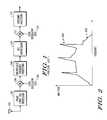
- FIG. 1is a block diagram of a conventional receiver.
- the receive antenna 100converts an incoming wireless radio frequency signal into an electrical signal.
- the bandwidth and passband of the radio front end circuit 102is matched to the incoming signal so as to extract the desired signal from out-of-band noise.
- the receiveralso includes mixer 104 and local oscillator 106 .
- the output of mixer 104is an intermediate frequency (IF) signal.
- the intermediate frequency detector 108amplifies and band-pass filters the IF signal and outputs it to the RFI suppressor 110 which helps to notch RFI from the signal. In spread spectrum signals, the RFI is easily isolated and extracted because its energy is concentrated out-of band or in a small spectrum range.
- a second mixer 112 and local oscillator 114which provide a baseband signal to a baseband processor 116 .
- UWB communication systemstransmit energy over a much larger bandwidth than normal “narrowband” or even spread-spectrum communication systems. Accordingly, it would be expected that the number of narrowband signals to be encountered by such UWB systems would be relatively high. Examples of such UWB systems include deRosa (U.S. Pat. No. 2,671,896), Robbins (U.S. Pat. No. 3,662,316), Morey (U.S. Pat. No. 3,806,795), Ross and Mara (U.S. Pat. No. 5,337,054) and Fullerton and Kowie (U.S. Pat. No. 5,6777,927).
- deRosaU.S. Pat. No. 2,671,896
- RobbinsU.S. Pat. No. 3,662,316
- MoreyU.S. Pat. No. 3,806,795
- Ross and MaraU.S. Pat. No. 5,337,054
- Fullerton and KowieU.S. Pat. No. 5,6777,92
- the challengeis to correctly receive an intended, transmitted UWB signal at the UWB receiver in the presence of narrowband interference signals in a post-correlation portion of the receiver circuitry where the processing load is small enough to be done in an inexpensive and low power communication system.
- An object of the present inventionis to provide a UWB receiver that includes an RFI extraction mechanism that suppresses at baseband, unwanted in-band RFI without adversely affecting the reception of the intended UWB signal.
- Another object of the present inventionis to provide a UWB receiver that includes an RFI extraction mechanism that estimates, in the baseband signal after correlation, the intended UWB signal.
- Another object of the present inventionis to provide a UWB receiver that includes an adaptable RFI extraction mechanism, as well as a method and computer program product, for extracting the RFI in the baseband signal after correlation.
- Another object of the present inventionis to provide a UWB receiver that passes UWB signals, but suppresses carrier-based modulated signals (i.e. narrowband signals).
- Another feature of the present inventionis to address the above-identified and other deficiencies of conventional communication systems and methods.
- UWB receiverthat employs a matched filter correlator, an analog to digital (A/D) converter that samples the UWB signal after correlation and an RFI extraction mechanism to identify the RFI signal after the correlation process and remove the RFI.
- A/Danalog to digital
- one embodimentwould include an RFI removal filter after the A/D converter that passes the desired data signal, but cancels an RFI signal.
- Another embodimentwould include an RFI removal filter and a bit detector after the A/D converter to cancel the RFI signal and extract the transmitted information.
- Another embodimentwould include the same RFI removal filter and bit detector along with an RFI estimator for adapting the filter to cancel observed RFI.
- FIG. 1is a block diagram of a conventional receiver
- FIG. 2is a spectral plot of a UWB signal with noise and RFI tones riding thereon;
- FIG. 3 A( 1 )is a block diagram of an ultra-wide band (UWB) transceiver, according to the present invention
- FIG. 3 A( 2 )is a diagram for illustrating the operation of the transceiver of FIG. 3 A( 1 ), according to the present invention
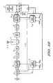
- FIG. 3Bis a block diagram of the transceiver of FIG. 3 A( 1 ), that manipulates a shape of UWB pulses, according to the present invention
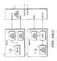
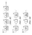
- FIG. 3Cis a block diagram of a UWB receiver with an RFI extraction mechanism according to the present invention.
- FIG. 3Dis a block diagram of one embodiment of a UWB receiver with a basic filter for RFI extraction
- FIG. 3Eis a block diagram of one embodiment of a UWB receiver that employs an RFI extraction algorithm
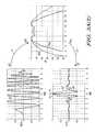
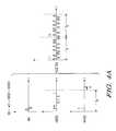
- FIG. 4Ais a time-domain plot of an incoming UWB signal with constituent parts that are used to create the UWB signal;
- FIGS. 4B-4Eare a signal flow diagram of a UWB incoming signal at various points in the UWB receiver
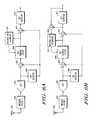
- FIGS. 5A-5Bare block diagrams of other embodiments of a UWB receiver with a bit detector as part of the RFI extraction mechanism;
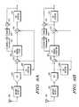
- FIG. 6Ais a block diagram of an embodiment of a UWB receiver with an adaptive filter for improved RFI extraction
- FIG. 6Bis a block diagram of another embodiment of a UWB receiver with an adaptive filter for improved RFI extraction
- FIG. 6Cis a block diagram of an embodiment of a UWB receiver with an adaptive algorithm for improved RFI extraction
- FIG. 6Dis a block diagram of another embodiment of a UWB receiver with an adaptive algorithm for improved RFI extraction
- FIG. 7Ais a flowchart of a process employed by the RFI extraction mechanism of FIG. 6A that adaptively extracts RFI;
- FIG. 7Bis a flowchart of a process employed by the RFI extraction mechanism of FIG. 6B that adaptively extracts RFI;
- FIG. 7Cis a flowchart of a process employed by the RFI extraction mechanism of FIG. 6C that adaptively extracts RFI;
- FIG. 7Dis a flowchart of a process employed by the RFI extraction mechanism of FIG. 6D that adaptively extracts RFI;
- FIGS. 8A-8Bare block diagrams of embodiments of a UWB receiver with a controller as part of the RFI extraction mechanism
- FIG. 9is a block diagram of the controller of FIG. 8 used to adaptively adjust the matched filter for extracting RFI.
- FIG. 10shows a processor system upon which an embodiment of the present invention may be implemented.
- FIG. 2shows the spectrum of the receive signal detected at the antenna of the UWB receiver.
- the incoming signalis contaminated with RFI tones 200 (or narrowband signals) and noise 212 .
- the white noise 212 and RFI tones 200are combined with the intended UWB signal.
- the RFI tonesare typically multiple in number and distributed in frequency throughout the UWB signal band.
- FIG. 2also shows the omni-present additive Gaussian white noise that is distributed throughout the UWB band.
- FIG. 3 A( 1 )is a block diagram of an ultra-wide band (UWB) transceiver.
- the transceiverincludes three major components, namely, receiver 11 , radio controller and interface 9 , and transmitter 13 .
- the systemmay be implemented as a separate receiver 11 and radio controller and interface 9 , and a separate transmitter 13 and radio controller and interface 9 .
- the radio controller and interface 9serves as a media access control (MAC) interface between the UWB wireless communication functions implemented by the receiver 11 and transmitter 13 and applications that use the UWB communications channel for exchanging data with remote devices.
- MACmedia access control
- the receiver 11includes an antenna 1 that converts a UWB electromagnetic waveform into an electrical signal (or optical signal) for subsequent processing.
- the UWB signalis generated with a sequence of shape-modulated wavelets, where the occurrence times of the shape-modulated wavelets may also be modulated.
- the shape control parametersis modulated with the analog signal. More typically, the wavelets take on M possible shapes. Digital information is encoded to use one or a combination of the M wavelet shapes and occurrence times to communicate information.
- each waveletcommunicates one bit, for example, using two shapes such as bi-phase.
- each waveletmay be configured to communicate nn bits, where M ⁇ 2 nn .
- four shapesmay be configured to communicate two bits, such as with quadrature phase or four-level amplitude modulation.
- each waveletis a “chip” in a code sequence, where the sequence, as a group, communicates one or more bits. The code can be M-ary at the chip level, choosing from M possible shapes for each chip.
- UWB waveformsare modulated by a variety of techniques including but not limited to: (i) bi-phase modulated signals (+1, ⁇ 1), (ii) multilevel bi-phase signals (+1, ⁇ 1, +a 1 , ⁇ a 1 , +a 2 , ⁇ a 2 , . . . , +aN, ⁇ aN), (iii) quadrature phase signals (+1, ⁇ 1, +j, ⁇ j), (iv) multi-phase signals (1, ⁇ 1, exp(+j ⁇ /N), exp( ⁇ j ⁇ /N), exp(+j ⁇ 2/N), exp( ⁇ j ⁇ 2/N), . . .
- any combination of the above waveformssuch as multi-phase channel symbols transmitted according to a chirping signaling scheme.
- the present inventionis applicable to variations of the above modulation schemes and other modulation schemes (e.g., as described in Lathi, “Modern Digital and Analog Communications Systems,” Holt, Rinehart and Winston, 1998, the entire contents of which is incorporated by reference herein), as will be appreciated by those skilled in the relevant art(s).
- the signal T icould be encoded for data, part of a spreading code or user code, or some combination thereof.
- a and kmay also be chosen from a finite set based on the user code or encoded data.
- Equation 1can be used to represent a sequence of exemplary transmitted or received pulses, where each pulse is a shape modulated UWB wavelet, g B i (t ⁇ T i ).
- the subscript irefers to the i th pulse in the sequence of UWB pulses transmitted or received.
- the wavelet function ghas M possible shapes, and therefore B i represents a mapping from the data, to one of the M-ary modulation shapes at the i th pulse in the sequence.
- the wavelet generator hardwaree.g., the UWB waveform generator 17
- the encoder 21combines the data stream and codes to generate the M-ary states. Demodulation occurs in the waveform correlator 5 and the radio controller and interface 9 to recover to the original data stream. Time position and wavelet shape are combined into the pulse sequence to convey information, implement user codes, etc.
- function fdefines a basic wavelet shape
- function his simply the Hilbert transform of the function f.
- the parameters ⁇ B i,2 , B i,3 , . . . ⁇represent a generic group of parameters that control the wavelet shape.
- An exemplary waveform sequence x(t)can be based on a family of wavelet pulse shapes f that are derivatives of a Guassian waveform as defined by Equation 3 below.
- f B i ⁇ ( t )⁇ ⁇ ( B i , 2 , B i , 3 ) ⁇ ( d B i , 3 dt B i , 3 ⁇ ⁇ - [ B i , 2 t ] 2 ) ( 3 )
- the function ⁇ ( )normalizes the peak absolute value of f B i (t) to 1.
- the parameter B i,2controls the pulse duration and center frequency.
- the parameter B i,3is the number of derivatives and controls the bandwidth and center frequency.
- Another exemplary waveform sequence x(t)can be based on a family of wavelet pulse shapes f that are Gaussian weighted sinusoidal functions, as described by Equation 4 below.
- b icontrols the pulse duration
- ⁇ icontrols the center frequency
- k icontrols a chirp rate.
- Other exemplary weighting functions, beside Gaussian, that are also applicable to the present inventioninclude, for example, Rectangular, Hanning, Hamming, Blackman-Harris, Nutall, Taylor, Kaiser, Chebychev, etc.
- Another exemplary waveform sequence x(t)can be based on a family of wavelet pulse shapes f that are inverse-exponentially weighted sinusoidal functions, as described by Equation 5 below.
- ⁇ ⁇ ⁇ B i , 2 , B i , 3 , B i , 4 , B i , 5 , B i , 6 , B i , 7 , B i , 8 ⁇⁇ t 1 i , t 2 i , t r i , t
- the leading edge turn on timeis controlled by t 1
- the turn-on rateis controlled by tr.
- the trailing edge turn-off timeis controlled by t 2
- the turn-off rateis controlled by tf.
- the starting phaseis controlled by ⁇
- the starting frequencyis controlled by ⁇
- the chirp rateis controlled by k
- the stopping frequencyis controlled by ⁇ +kT D .
- a feature of the present inventionis that the M-ary parameter set used to control the wavelet shape is chosen so as to make a UWB signal, wherein the center frequency f c and the bandwidth B of the power spectrum of g(t) satisfies 2f c >B>0.25f c .
- conventional equationsdefine in-phase and quadrature signals (e.g., often referred to as I and Q) as sine and cosine terms.
- I and Qin-phase and quadrature signals
- This conventional definitionis inadequate for UWB signals.
- the present inventionrecognizes that use of such conventional definition may lead to DC offset problems and inferior performance.
- the matched filter output of the UWB signalis typically only a few cycles, or even a single cycle.
- the parameter n in Equation 3 abovemay only take on low values (e.g., such as those described in co-pending U.S. patent application Ser. No. 09/209,460.
- the compressed (i.e., coherent matched filtered) pulse width of a UWB waveletwill now be defined with reference to FIG. 3 A( 2 ).
- the time domain version of the waveletthus represents g(t) and the Fourier transform (FT) version is represented by G( ⁇ ).
- the output of the matched filter in the time domainis seen by performing an inverse Fourier transform (IFT) on P( ⁇ ) so as to obtain p(t), the compressed or matched filtered pulse.
- IFTinverse Fourier transform
- the width of the compressed pulse p(t)is defined by T C , which is the time between the points on the envelope of the compressed pulse E(t) that are 6 dB below the peak thereof, as shown in FIG. 3 A( 2 ).
- the above-noted parameterized waveformsare examples of UWB wavelet functions that can be controlled to communicate information with a large parameter space for making codes with good resulting autocorrelation and cross-correlation functions.
- each of the parametersis chosen from a predetermined list according to an encoder that receives the digital data to be communicated.
- at least one parameteris changed dynamically according to some function (e.g., proportionally) of the analog signal that is to be communicated.
- the electrical signals coupled in through the antenna 1are passed to a radio front end 3 .
- the radio front end 3processes the electric signals so that the level of the signal and spectral components of the signal are suitable for processing in the UWB waveform correlator 5 .
- the UWB waveform correlator 5correlates the incoming signal (e.g., as modified by any spectral shaping, such as a matched filtering, partially matched filtering, simply roll-off, etc., accomplished in front end 3 ) with different candidate signals generated by the receiver 11 , so as to determine when the receiver 11 is synchronized with the received signal and to determine the data that was transmitted.
- the timing generator 7 of the receiver 11operates under control of the radio controller and interface 9 to provide a clock signal that is used in the correlation process performed in the UWB waveform correlator 5 .
- the UWB waveform correlator 5correlates in time a particular pulse sequence produced at the receiver 11 with the receive pulse sequence that was coupled in through antenna 1 and modified by front end 3 .
- the UWB waveform correlator 5provides high signal to noise ratio (SNR) data to the radio controller and interface 9 for subsequent processing.
- SNRsignal to noise ratio
- the output of the UWB waveform correlator 5is the data itself.
- the UWB waveform correlator 5simply provides an intermediate correlation result, which the radio controller and interface 9 uses to determine the data and determine when the receiver 11 is synchronized with the incoming signal.
- the radio controller and interface 9when synchronization is not achieved (e.g., during a signal acquisition mode of operation), the radio controller and interface 9 provides a control signal to the receiver 11 to acquire synchronization. In this way, a sliding of a correlation window within the UWB waveform correlator 5 is possible by adjustment of the phase and frequency of the output of the timing generator 7 of the receiver 11 via a control signal from the radio controller and interface 9 .
- the control signalcauses the correlation window to slide until lock is achieved.
- the radio controller and interface 9is a processor-based unit that is implemented either with hard wired logic, such as in one or more application specific integrated circuits (ASICs) or in one or more programmable processors.
- ASICsapplication specific integrated circuits
- the receiver 11provides data to an input port (“RX Data In”) of the radio controller and interface 9 .
- An external processvia an output port (“RX Data Out”) of the radio controller and interface 9 , may then use this data.
- the external processmay be any one of a number of processes performed with data that is either received via the receiver 11 or is to be transmitted via the transmitter 13 to a remote receiver.
- the radio controller and interface 9receives source data at an input port (“TX Data In”) from an external source.
- TX Data Outapplies the data to an encoder 21 of the transmitter 13 via an output port (“TX Data Out”).
- the radio controller and interface 9provides control signals to the transmitter 13 for use in identifying the signaling sequence of UWB pulses.
- the receiver 11 and the transmitter 13 functionsmay use joint resources, such as a common timing generator and/or a common antenna, for example.
- the encoder 21receives user coding information and data from the radio controller and interface 9 and preprocesses the data and coding so as to provide a timing input for the UWB waveform generator 17 , which produces UWB pulses encoded in shape and/or time to convey the data to a remote location.
- the encoder 21produces the control signals necessary to generate the required modulation.
- the encoder 21may take a serial bit stream and encode it with a forward error correction (FEC) algorithm (e.g., such as a Reed Solomon code, a Golay code, a Hamming code, a Convolutional code, etc.).
- FECforward error correction
- the encoder 21may also interleave the data to guard against burst errors.
- the encoder 21may also apply a whitening function to prevent long strings of “ones” or “zeros.”
- the encoder 21may also apply a user specific spectrum spreading function, such as generating a predetermined length chipping code that is sent as a group to represent a bit (e.g., inverted for a “one” bit and non-inverted for a “zero” bit, etc.).
- the encoder 21may divide the serial bit stream into subsets in order to send multiple bits per wavelet or per chipping code, and generate a plurality of control signals in order to affect any combination of the modulation schemes as described above (and/or as described in Lathi).
- the radio controller and interface 9may provide some identification, such as user ID, etc., of the source from which the data on the input port (“TX Data In”) is received.
- this user IDmay be inserted in the transmission sequence, as if it were a header of an information packet.
- the user IDitself may be employed to encode the data, such that a receiver receiving the transmission would need to postulate or have a priori knowledge of the user ID in order to make sense of the data.
- the IDmay be used to apply a different amplitude signal (e.g., of amplitude “f”) to a fast modulation control signal to be discussed with respect to FIG. 3B, as a way of impressing the encoding onto the signal.
- the output from the encoder 21is applied to a UWB waveform generator 17 .
- the UWB waveform generator 17produces a UWB pulse sequence of pulse shapes at pulse times according to the command signals it receives, which may be one of any number of different schemes.
- the output from the UWB generator 17is then provided to an antenna 15 , which then transmits the UWB energy to a receiver.
- the datamay be encoded by using the relative spacing of transmission pulses (e.g., PPM, chirp, etc.).
- the datamay be encoded by exploiting the shape of the pulses as described above (and/or as described in Lathi). It should be noted that the present invention is able to combine time modulation (e.g., such as pulse position modulation, chirp, etc.) with other modulation schemes that manipulate the shape of the pulses.
- the system according to the present inventionhas improved capability, allowing many transceiver units to operate in close proximity without suffering from interference from one another.
- FIG. 3Bis a block diagram of a transceiver embodiment of the present invention in which the modulation scheme employed is able to manipulate the shape and time of the UWB pulses.
- the modulation scheme employedis able to manipulate the shape and time of the UWB pulses.
- the antenna 1 , 15e.g., corresponding antennas 1 and 15 of FIG. 3 A( 1 ) the energy is coupled in to a transmit/receive (T/R) switch 27 , which passes the energy to a radio front end 3 .
- the radio front end 3filters, extracts noise, and adjusts the amplitude of the signal before providing the same to a splitter 29 .
- the splitter 29divides the signal up into one of N different signals and applies the N different signals to different tracking correlators 31 1 - 31 N .
- Each of the tracking correlators 31 1 - 31 Nreceives a clock input signal from a respective timing generator 7 1 - 7 N of a timing generator module 7 , 19 ,
- the timing generators 7 1 - 7 Nfor example, receive a phase and frequency adjustment signal, as shown in FIG. 3B, but may also receive a fast modulation signal or other control signal(s) as well.
- the radio controller and interface 9provides the control signals, such as phase, frequency and fast modulation signals, etc., to the timing generator module 7 , 19 , for time synchronization and modulation control.
- the fast modulation control signalmay be used to implement, for example, chirp waveforms, PPM waveforms, such as fast time scale PPM waveforms, etc.
- the radio controller and interface 9also provides control signals to, for example, the encoder 21 , the waveform generator 17 , the filters 23 , the amplifier 25 , the T/R switch 27 , the front end 3 , the tracking correlators 31 1 - 31 N (corresponding to the UWB waveform correlator 5 of FIG. 3 A( 1 ), etc., for controlling, for example, amplifier gains, signal waveforms, filter passbands and notch functions, alternative demodulation and detecting processes, user codes, spreading codes, cover codes, etc.
- the radio controller and interface 9adjusts the phase input of, for example, the timing generator 7 1 , in an attempt for the tracking correlator 31 1 to identify and the match the timing of the signal produced at the receiver with the timing of the arriving signal.
- the radio controller and interface 9senses the high signal strength or high SNR and begins to track, so that the receiver is synchronized with the received signal.
- the receiverwill operate in a tracking mode, where the timing generator 7 1 is adjusted by way of a continuing series of phase adjustments to counteract any differences in timing of the timing generator 7 1 and the incoming signal.
- a feature of the present inventionis that by sensing the mean of the phase adjustments over a known period of time, the radio controller and interface 9 adjusts the frequency of the timing generator 7 1 so that the mean of the phase adjustments becomes zero. The frequency is adjusted in this instance because it is clear from the pattern of phase adjustments that there is a frequency offset between the timing generator 7 1 and the clocking of the received signal. Similar operations may be performed on timing generators 7 2 - 7 N , so that each receiver can recover the signal delayed by different amounts, such as the delays caused by multipath (i.e., scattering along different paths via reflecting off of local objects).
- a feature of the transceiver in FIG. 3Bis that it includes a plurality of tracking correlators 31 1 - 31 N .
- a plurality of tracking correlators 31 1 - 31 NBy providing a plurality of tracking correlators, several advantages are obtained. First, it is possible to achieve synchronization more quickly (i.e., by operating parallel sets of correlation arms to find strong SNR points over different code-wheel segments). Second, during a receive mode of operation, the multiple arms can resolve and lock onto different multipath components of a signal. Through coherent addition, the UWB communication system uses the energy from the different multipath signal components to reinforce the received signal, thereby improving signal to noise ratio. Third, by providing a plurality of tracking correlator arms, it is also possible to use one arm to continuously scan the channel for a better signal than is being received on other arms.
- the communications systemdynamically adapts to changing channel conditions.
- the radio controller and interface 9receives the information from the different tracking correlators 31 1 - 31 N and decodes the data.
- the radio controller and interface 9also provides control signals for controlling the front end 3 , e.g., such as gain, filter selection, filter adaptation, etc., and adjusting the synchronization and tracking operations by way of the timing generator module 7 , 19 .
- radio controller and interface 9serves as an interface between the communication link feature of the present invention and other higher level applications that will use the wireless UWB communication link for performing other functions.
- Some of these functionswould include, for example, performing range-finding operations, wireless telephony, file sharing, personal digital assistant (PDA) functions, embedded control functions, location-finding operations, etc.
- a timing generator 7 0On the transmit portion of the transceiver shown in FIG. 3B, a timing generator 7 0 also receives phase, frequency and/or fast modulation adjustment signals for use in encoding a UWB waveform from the radio controller and interface 9 .
- Data and user codes(via a control signal) are provided to the encoder 21 , which in the case of an embodiment of the present invention utilizing time-modulation, passes command signals (e.g., ⁇ t) to the timing generator 7 0 for providing the time at which to send a pulse. In this way, encoding of the data into the transmitted waveform may be performed.
- the encoder 21When the shape of the different pulses are modulated according to the data and/or codes, the encoder 21 produces the command signals as a way to select different shapes for generating particular waveforms in the waveform generator 17 .
- the datamay be grouped in multiple data bits per channel symbol.
- the waveform generator 17then produces the requested waveform at a particular time as indicated by the timing generator 7 0 .
- the output of the waveform generatoris then filtered in filter 23 and amplified in amplifier 25 before being transmitted via antenna 1 , 15 by way of the T/R switch 27 .
- the transmit poweris set low enough that the transmitter and receiver are simply alternately powered down without need for the T/R switch 27 .
- neither the filter 23 nor the amplifier 25is needed, because the desired power level and spectrum is directly useable from the waveform generator 17 .
- the filters 23 and the amplifier 25may be included in the waveform generator 17 depending on the implementation of the present invention.
- a feature of the UWB communications system disclosedis that the transmitted waveform x(t) can be made to have a nearly continuous power flow, for example, by using a high chipping rate, where the wavelets g(t) are placed nearly back-to-back.
- This configurationallows the system to operate at low peak voltages, yet produce ample average transmit power to operate effectively.
- sub-micron geometry CMOS switchesfor example, running at one-volt levels, can be used to directly drive antenna 1 , 15 , such that the amplifier 25 is not required. In this way, the entire radio can be integrated on a single monolithic integrated circuit.
- the systemcan be operated without the filters 23 . If, however, the system is to be operated, for example, with another radio system, the filters 23 can be used to provide a notch function to limit interference with other radio systems. In this way, the system can operate simultaneously with other radio systems, providing advantages over conventional devices that use avalanching type devices connected straight to an antenna, such that it is difficult to include filters therein.
- FIG. 3Cis a block diagram of a UWB receiver with an RFI extraction mechanism according to one embodiment of the present invention.
- RF Energyis transmitted to the UWB receiver and coupled in to the antenna 100 .
- the receiverincludes a UWB front end processor 302 , which sets a passband and adjusts signal levels before subsequent processing.
- the received UWB signal, noise, and RFI tonesare sent to a signal correlator 304 that performs a matched filter operation by correlating the received signal with a copy of the user's coded signal applied to a wavelet series. More particularly, the UWB waveform is originally created by a series of wavelets arranged according to a user specified spreading code.
- the correlator 304correlates a local copy of the UWB waveform (absent the data but with any user code) with the received copy to extract the data. After correlation, the signal is passed to RFI suppressor 110 . After RFI is extracted, data contained in the original signal is detected in signal detector 306 , and subsequently output.
- the A/D converteris set to a predetermined sample rate.
- the sample rateis set to be equal to the bit period of the bits (or channel symbols) output from the signal correlator 304 .
- the sample timesare synchronized to the peak levels of the information bit waveforms.
- the RFI tones in the incoming signalare sampled at the rate of the A/D converter and consequently, under sampled (i.e., sampled at less than the Nyquist rate). By undersampling, the RFI tones will “alias” into the detection bandwidth.
- the RFI interferers that have higher frequenciesare actually aliased down to the same frequency band in which the signal detection processing occurs.
- the present inventorsrecognized that the actual position of the alias terms are not important, as long as the narrowband nature of the RFI is preserved.
- One processing feature that helps to preserve the narrowband nature of the RFIis to use an A/D converter that is stable, and a signaling scheme that produces data bits at a fixed interval. This way the A/D sample times can be precisely timed to occur where peak outputs of the correlator occur, which also happen to be the optimum times to perform data bit detection. With the narrowband nature of the RFI preserved, the inventors found that it is then possible to easily extract and/or suppress the RFI.
- the sample timesare noise like, so the RFI alias into noise instead of aliasing to a tone.
- the PPM pulse ratesare much lower that can be afforded by shape modulation where the pulses can be sent with substantially no gap between pulses. Due to the low pulse rates and the purposefully jittered clock, previous PPM systems are incapable of applying this technique.
- the disclosed UWB communication systemis architected such that the A/D converter is sampling with a stable, low jitter clock capable of preserving the aliased tones. Even in PPM modes of operation, the A/D converter, over some predetermined number of cycles, provides a fixed sampling interval so that the disclosed system may affect RFI removal.
- One, or combinations, of the following parameterscan be adjusted to alter the effectiveness of RFI extraction: sample rate, vector length, and number of quantization levels of the signal.
- the sample ratecan be adjusted higher, resulting in less spectral folding and greater resolution for determining peak correlation levels used to make bit decisions.
- undersamplingenables the use of less costly components than the expensive A/D converters that sample fast enough to fully represent the correlation result.
- the vector lengthcan also be adjusted. If the vector length, i.e., number of samples analyzed while performing RFI detection, is large, processing time is increased, but there is a greater amount of redundancy in the RFI so the RFI tones may be isolated more precisely are may, therefore, be suppressed to a greater degree.
- a short vector lengthenables faster processing, but with larger loss of signal strength when RFI is extracted.
- the number of quantization levels of the signal under analysismay also be adjusted by changing the bit width of the A/D converter. A higher number of quantization levels gives better resolution of RFI and hence, more effective extraction because the RFI can be characterized better.
- One or more of these parameterscan be adjusted alone or in any combination in the embodiments below to affect RFI extraction.
- FIG. 3Dis a block diagram of one embodiment of the present invention in which there is a UWB receiver with pre and post A/D conversion matched filters for RFI extraction.
- the signalis converted to an electrical signal and applied to a matched filter 402 .
- narrowband RFI excision circuitrymay also be applied to the signal from the antenna to provide an initial degree of RFI suppression.
- the signalthen goes to A/D converter 404 where it is digitized at a rate that corresponds with the bit rate.
- bitdoes not necessarily relate to a new information bit, but may also be an encoded bit or other discrete component of a baseband data stream that may or may not be output directly to an end user.
- the sampled signalis applied to RFI removal filter 406 , where the filter further extracts residual RFI.
- the resulting signalis the intended data signal plus white Gaussian noise.
- FIG. 3Eis the same as FIG. 3D, except RFI removal filter 406 has been replaced by RFI removal algorithm 407 .
- RFI removal algorithmsencompass both time-domain and frequency-domain estimate-and-subtract techniques. The references for these techniques, as well as the references for construction of RFI removal filters, can be found in the Description of the Background.
- FIG. 4Ashows the composition of an incoming UWB signal s(t).
- a wavelet w(t)is convolved with a user code signal “code (t)” and input data “data(t)”.
- the code sequencehas the pattern +1, +1, ⁇ 1, ⁇ 1, ⁇ 1, +1 and corresponds with a particular user.
- the data(presumably from a user and presumed to be binary in this non-limiting example) consists of sequences of two bits, 1 and 0 , separated by a bit period T b . So, the data, convolved with a particular user's code sequence and a wavelet, is represented by s(t).
- the first data bit, 1is spread over bit period T b in an encoded pattern of wavelets that corresponds with the user's code.
- the second data bit, 0is also spread over a second bit period T b but with inverted wavelets indicative of the data bit being a “zero”.
- the signalis similarly composed for subsequent data bits over bit period T b .
- the resulting UWB signal s(t)is a piecewise continuous UWB waveform.
- FIGS. 4B-4Eshow the incoming UWB signal at various locations in the receiver of the first embodiment in FIG. 3 D.
- the incoming signalincludes the UWB signal as described in FIG. 4 A and an RFI interferer, r(t), which is viewed as a sinusoidal signal.
- the incoming signalgoes through matched filter 402 (MF 1 ), where the incoming signal is correlated with a local copy of the UWB signal (although absent the data).
- Matched filter 402may be viewed as a matched filer because it recreates the wavelet stream generated at the transmitter and correlates the local UWB signal with the received UWB signal.
- the RFImixed with the incoming signal, passes through unscathed in terms of its “narrowband” attributes although perhaps reduced in amplitude by virtue of the spectral shaping performed by the matched filter.
- the output of matched filter 402is the correlated signals separated by bit period T b . Notice that the sample of FIG. 4C shows a high signal to interference ratio, which allows the UWB data signal to be easily recognizable.
- the data signalis represented by a series of sample points at regular intervals of T b (i.e., one sample point per bit in this example).
- A/D converter 404is set to a sample rate that is the same as bit period T b of the incoming signal, which enables the use of a lower cost A/D converter for this “carrier less” communications scheme.
- the signalhas an amplitude of A and ⁇ A, where A indicates the signal level for a bit encoded as a “1” and ⁇ A indicates the signal level for a bit encoded as a “O” of the incoming signal.
- the amplitudevaries because of the RFI and noise and so at the detector the variation in the signal is designated ⁇ , in FIGS.
- RFI removal filter 406RFI is extracted from the signal by any one of a variety of techniques, as will be discussed. It should be noted that the RFI, in all likelihood, will have been undersampled. The RFI will tend to have a progressive pattern-effect on the sampled data. For example, the RFI may appear to modulate the data samples, such that the data samples will all not stay tightly clustered around A (or ⁇ A), but rather vary in some predictable pattern.
- the UWB piecewise wavelet transmission scheme and receive scheme according to the present inventionpreserves the narrowand attribute of the RFI, it is clear that in the absence of the strong RFI, and at high SNR, the data should be tightly clustered at A, ⁇ A, but if it is not, then it is likely that the RFI is the culprit.
- the signalfollows a bit pattern with amplitudes at A or ⁇ A without the variations resulting from RFI (presuming a high SNR and perfect excision of the RFI).
- FIG. 5Ashows another embodiment of the present invention in which a UWB receiver uses bit detection to facilitate RFI extraction in the RFI removal filter.
- the signalis received at antenna 100 , and processed by matched filter 402 and the A/D converter 404 .
- the data bits from the digitized signalare detected in first bit detector 408 .
- the bit detector 408estimates the desired signal consisting of the bit values and amplitudes.
- the output of first bit detector 408⁇ circumflex over (b) ⁇ , is subtracted from the digitized signal at summer 405 .
- the output of summer 405is the RFI estimate plus noise.
- the RFIgoes into RFI removal filter 406 , where RFI is detected and removed.
- the remaining signal from RFI removal filter 406is added to the output of first bit detector 408 at summer 410 to produce a “cleaned” data signal.
- the output of summer 410goes to second bit detector 412 , where the incoming data bits are again detected.
- the result of the output of second bit detector 412is a good signal with the RFI cancelled.
- the RFI signalmay be cancelled at other locations as well, such as in the matched filter or in the downstream processor.
- FIG. 5Bis the same as FIG. 5A, except RFI removal filter 406 has been replaced by RFI removal algorithm 407 .
- FIG. 6Ashows an embodiment of the present invention in which a UWB receiver includes an adaptive filter for RFI extraction. Similar to FIGS. 3 and 5, the signal is received at antenna 100 , processed by the matched filter 402 , and digitized at A/D converter 404 . As in the previous embodiment, the digitized signal goes into first bit detector 408 , where an estimate of the desired signal is derived. The output of first bit detector 408 is subtracted from the digitized signal at summer 405 . The output of summer 405 is the RFI estimate plus noise. The RFI goes into RFI removal filter 406 , where RFI is filtered. The output from RFI removal filter 406 goes to residual RFI estimator 414 , which estimates residual RFI in that output.
- estimator 414dispatches a control signal to RFI removal filter 406 to update the filter so that it can remove observed RFI signals.
- RFI removal filter 406is then adapted to include the estimated RFI to improve extraction in subsequent incoming signals.
- the output of RFI removal filter 406is added to the output of first bit detector 408 at summer 410 .
- the output of summer 410goes to second bit detector 412 , where the UWB signal is further extracted.
- the RFI signalmay be cancelled at other locations as well, such as in the matched filter or in the downstream processor.
- FIG. 6Bshows another embodiment of the present invention in which a UWB receiver includes an adaptive filter for RFI extraction. Similar to FIG. 6A, RFI removal filter 406 is adaptively updated to remove residual RFI. In this embodiment of FIG. 6B, the output of second bit detector 412 is subtracted from the output of summer 410 at summer 416 . The output of summer 416 goes into residual RFI estimator 414 , where a good estimate of RFI is made. As in FIG. 6A, if the observed residual RFI is above a predetermined threshold (or other metric appropriate for the type of RFI experienced), estimator 414 dispatches a control signal to RFI removal filter 406 to subtract the observed RFI signal. RFI removal filter 406 is then adjusted to include the estimated RFI to improve extraction in subsequent incoming signals. The RFI signal may be cancelled at other locations as well, such as in the matched filter or in the downstream processor.
- a predetermined thresholdor other metric appropriate for the type of RFI experienced
- FIG. 6Cis the same as FIG. 6A, except RFI removal filter 406 has been replaced by RFI removal algorithm 407 .
- FIG. 6Dis the same as FIG. 6B, except RFI removal filter 406 has been replaced by RFI removal algorithm 407 .
- RFI removal filter 406 in FIGS. 6A-6Badapts to the residual RFI tones, the output after RFI removal filter 406 moves toward that depicted in FIG. 4 E. That is, subsequent variations in the signal amplitude decrease to a point where the variations are dominated by white noise. At that point, RFI removal filter 406 matches the incoming RFI signal such that all significant RFI tones are removed in the incoming signal.
- FIG. 7Ais a flowchart of a method for adaptively and iteratively canceling RFI by adapting RFI removal filter 406 of FIG. 6 A.
- the processbegins with step S 702 , where RFI removal filter 406 is initialized as an allpass filter such that all RFI is passed unscathed.
- the incoming signali.e., data vector
- step S 703the incoming signal (i.e., data vector) goes through A/D converter 404 and is input to first bit detector 408 in step S 703 .
- step S 704estimates bit values and signal amplitude in the digitized signal.
- step S 706the estimated signal is subtracted from the digitized signal at summer 405 to get an estimate of the RFI.
- step S 708the RFI estimate from summer 405 is filtered.
- the estimate of the desired signal from first bit detector 408is added to the output of RFI removal filter 406 in summer 410 .
- step S 710The output of the RFI filter 406 is fed to a residual RFI estimation block 414 in step S 716 .
- the output of the residual RFI estimation blockis used to update the RFI removal filter in step S 718 .
- step S 720an inquiry is made whether the RFI extraction is iterative. If not, the output of summer 410 is fed to a second bit detector 412 in step S 712 .
- the signal detected from second bit detector 412is output in step S 724 .
- step S 703where more incoming data is processed. If the RFI extraction process is iterative, then a second inquiry is made in step S 722 whether all residual RFI has been removed. If not, the process returns to step S 704 and repeats. If all the residual RFI has been removed, then the output of summer 410 is fed to a second bit detector 412 in step S 712 . The signal detected from second bit detector 412 is output in step S 724 . The process then repeats beginning with step S 703 for more incoming data.
- FIG. 7Bis a flow chart of a method for adaptively canceling RFI by adapting RFI removal filter 406 as shown in FIG. 6 B.
- the processis similar to the process of FIG. 7 A. The exception lies in the process applied to update the RFI removal filter.
- step S 710in which the estimate of the desired signal from first bit detector 408 is added to the output of RFI removal filter 406 in summer 410
- the output of summer 410is applied to bit detector 412 in step S 712 .
- the output of second bit detector 412is subtracted from the output of summer 410 in step S 714 .
- the resultis the estimate of residual RFI in the signal.
- step S 716the output of summer 416 is estimated in estimator 414 . Based on the estimate of the RFI remaining in the signal, RFI removal filter 416 is updated in step S 718 .
- FIG. 7Cis the same as FIG. 7A, except blocks 5702 , 5708 , and 5718 have been replaced by blocks 5701 , 5709 , and 5719 , respectively.
- FIG. 7Dis the same as FIG. 7B, except blocks 5702 , 5708 , and 5718 have been replaced by blocks 5701 , 5709 , and 5719 , respectively.
- FIG. 8Ashows another embodiment of an adaptive RFI mechanism similar to FIG. 6B, with the exception of a controller 418 and a sensor 420 that replace the residual RFI estimator 414 of FIG. 6 B.
- Sensor 420detects the RFI in the output of the summer 416 .
- the controller 418calculates the required setting of RFI removal filter 406 in order to extract the residual RFI.
- the controller 418sends the setting to RFI removal filter 406 , which then adapts for subsequent incoming signals.
- FIG. 8Bis the same as FIG. 8A, except RFI removal filter 406 has been replaced by RFI removal algorithm 407 .
- FIG. 9shows an embodiment of the controller 418 of FIG. 8 .
- the controller 418includes a CPU 804 that communicates with other components in the controller by way of a bus 806 .
- the bus 806interconnects a main memory 808 , which may be a random access memory (RAM) or other dynamic storage devices (e.g., dynamic RAM (DRAM), static RAM (SRAM), and synchronous DRAM (SDRAM)) holding different values, such as settings to be adjusted by RFI removal filter 406 .
- RAMrandom access memory
- DRAMdynamic RAM
- SRAMstatic RAM
- SDRAMsynchronous DRAM
- a storage device 810is possibly a semiconductor memory although it may be a magnetic hard drive or a removable media drive (e.g., a floppy disk drive, a read-only compact disk drive, a read/write compact disk drive, a compact disk jukebox, a tape drive, and a removal magneto-optical drive), is also included so that different identification and control processes may be loaded into the CPU 804 for extracting different RFI.
- the bus 806also interconnects the CPU 804 with a communication interface 802 that receives information from the sensor 420 and also provides the output signal.
- the communications interface 802may be a discrete line, or also conventional IO port, such as a parallel port, serial port, or merely a local-bus or control line.
- the UWB transceiver of FIGS. 3 A( 1 ), 3 A( 2 ), and 3 Bmay be used to perform a radio transport function for interfacing with different applications as part of a stacked protocol architecture.
- the UWB transceiverperforms signal creation, transmission and reception functions as a communications service to applications that send data to the transceiver and receive data from the transceiver much like a wired I/O port.
- the UWB transceivermay be used to provide a wireless communications function to any one of a variety of devices that may include interconnection to other devices either by way of wired technology or wireless technology.
- 3Bmay be used as part of a local area network (LAN) connecting fixed structures or as part of a wireless personal area network (WPAN) connecting mobile devices, for example.
- LANlocal area network
- WPANwireless personal area network
- all or a portion of the present inventionmay be conveniently implemented in a microprocessor system using conventional general purpose microprocessors programmed according to the teachings of the present invention, as will be apparent to those skilled in the microprocessor systems art.
- Appropriate softwarecan be readily prepared by programmers of ordinary skill based on the teachings of the present disclosure, as will be apparent to those skilled in the software art.
- FIG. 10illustrates a processor system 1401 upon which an embodiment according to the present invention may be implemented.
- the system 1401includes a bus 1403 or other communication mechanism for communicating information, and a processor 1405 coupled with the bus 1403 for processing the information.
- the processor system 1401also includes a main memory 1407 , such as a random access memory (RAM) or other dynamic storage device (e.g., dynamic RAM (DRAM), static RAM (SRAM), synchronous DRAM (SDRAM), flash RAM), coupled to the bus 1403 for storing information and instructions to be executed by the processor 1405 .
- a main memory 1407may be used for storing temporary variables or other intermediate information during execution of instructions to be executed by the processor 1405 .
- the system 1401further includes a read only memory (ROM) 1409 or other static storage device (e.g., programmable ROM (PROM), erasable PROM (EPROM), and electrically erasable PROM (EEPROM)) coupled to the bus 1403 for storing static information and instructions for the processor 1405 .
- ROMread only memory
- PROMprogrammable ROM
- EPROMerasable PROM
- EEPROMelectrically erasable PROM
- a storage device 1411such as a magnetic disk or optical disc, can be provided and coupled to the bus 1403 for storing information and instructions.
- the processor system 1401may also include special purpose logic devices (e.g., application specific integrated circuits (ASICs)) or configurable logic devices (e.g., simple programmable logic devices (SPLDs), complex programmable logic devices (CPLDs), or re-programmable field programmable gate arrays (FPGAs)).
- ASICsapplication specific integrated circuits
- SPLDssimple programmable logic devices
- CPLDscomplex programmable logic devices
- FPGAsre-programmable field programmable gate arrays
- Other removable media devicese.g., a compact disc, a tape, and a removable magneto-optical media
- fixed, high density media drivesmay be added to the system 301 using an appropriate device bus (e.g., a small system interface (SCSI) bus, an enhanced integrated device electronics (IDE) bus, or an ultra-direct memory access (DMA) bus).
- SCSIsmall system interface
- IDEenhanced integrated device electronics
- DMAultra-direct memory access
- the system 1401may
- the processor system 1401may be coupled via the bus 1403 to a display 1413 , such as a cathode ray tube (CRT) or liquid crystal display (LCD) or the like, for displaying information to a system user.
- the display 1413may be controlled by a display or graphics card.
- the processor system 1401includes input devices, such as a keyboard or keypad 1415 and a cursor control 1417 , for communicating information and command selections to the processor 1405 .
- the cursor control 1417for example, is a mouse, a trackball, or cursor direction keys for communicating direction information and command selections to the processor 1405 and for controlling cursor movement on the display 1413 .
- a printermay provide printed listings of the data structures or any other data stored and/or generated by the processor system 1401 .
- the processor system 1401performs a portion or all of the processing steps of the invention in response to the processor 1405 executing one or more sequences of one or more instructions contained in a memory, such as the main memory 1407 .
- a memorysuch as the main memory 1407 .
- Such instructionsmay be read into the main memory 1407 from another computer-readable medium, such as a storage device 1411 .
- processors in a multi-processing arrangementmay also be employed to execute the sequences of instructions contained in the main memory 1407 .
- hard-wired circuitrymay be used in place of or in combination with software instructions. Thus, embodiments are not limited to any specific combination of hardware circuitry and software.
- the processor system 1401includes at least one computer readable medium or memory programmed according to the teachings of the invention and for containing data structures, tables, records, or other data described herein.
- the present inventionincludes software for controlling the system 1401 , for driving a device or devices for implementing the invention, and for enabling the system 1401 to interact with a human user.
- Such softwaremay include, but is not limited to, device drivers, operating systems, development tools, and applications software.
- Such computer readable mediafurther includes the computer program product of the present invention for performing all or a portion (if processing is distributed) of the processing performed in implementing the invention.
- the computer code devices of the present inventionmay be any interpreted or executable code mechanism, including but not limited to scripts, interpretable programs, dynamic link libraries, Java or other object oriented classes, and complete executable programs. Moreover, parts of the processing of the present invention may be distributed for better performance, reliability, and/or cost.
- Non-volatile mediaincludes, for example, optical, magnetic disks, and magneto-optical disks, such as the storage device 1411 .
- Volatile mediaincludes dynamic memory, such as the main memory 1407 .
- Transmission mediaincludes coaxial cables, copper wire and fiber optics, including the wires that comprise the bus 1403 . Transmission media may also take the form of acoustic or light waves, such as those generated during radio wave and infrared data communications.
- Computer readable mediainclude, for example, hard disks, floppy disks, tape, magneto-optical disks, PROMs (EPROM, EEPROM, Flash EPROM), DRAM, SRAM, SDRAM, or any other magnetic medium, compact disks (e.g., CD-ROM), or any other optical medium, punch cards, paper tape, or other physical medium with patterns of holes, a carrier wave, carrierless transmissions, or any other medium from which a system can read.
- Various forms of computer readable mediamay be involved in providing one or more sequences of one or more instructions to the processor 1405 for execution.
- the instructionsmay initially be carried on a magnetic disk of a remote computer.
- the remote computercan load the instructions for implementing all or a portion of the present invention remotely into a dynamic memory and send the instructions over a telephone line using a modem.
- a modem local to system 1401may receive the data on the telephone line and use an infrared transmitter to convert the data to an infrared signal.
- An infrared detector coupled to the bus 1403can receive the data carried in the infrared signal and place the data on the bus 1403 .
- the bus 1403carries the data to the main memory 1407 , from which the processor 1405 retrieves and executes the instructions.
- the instructions received by the main memory 1407may optionally be stored on a storage device 1411 either before or after execution by the processor 1405 .
- the processor system 1401also includes a communication interface 1419 coupled to the bus 1403 .
- the communications interface 1419provides a two-way UWB data communication coupling to a network link 1421 that is connected to a communications network 1423 such as a local network (LAN) or personal area network (PAN) 1423 .
- a communications network 1423such as a local network (LAN) or personal area network (PAN) 1423 .
- the communication interface 1419may be a network interface card to attach to any packet switched UWB-enabled personal area network (PAN) 1423 .
- the communication interface 1419may be a UWB accessible asymmetrical digital subscriber line (ADSL) card, an integrated services digital network (ISDN) card, or a modem to provide a data communication connection to a corresponding type of communications line.
- ADSLasymmetrical digital subscriber line
- ISDNintegrated services digital network
- the communications interface 1419may also include the hardware to provide a two-way wireless communications coupling other than a UWB coupling, or a hardwired coupling to the network link 1421 .
- the communications interface 1419may incorporate the UWB transceiver of FIG. 3 A( 1 ) and/or FIG. 3B as part of a universal interface that includes hardwired and non-UWB wireless communications coupling to the network link 1421 .
- the network link 1421typically provides data communication through one or more networks to other data devices.
- the network link 1421may provide a connection through a LAN to a host computer 1425 or to data equipment operated by a service provider, which provides data communication services through an IP (Internet Protocol) network 1427 .
- the network link 1421may provide a connection through a PAN 1423 to a mobile device 1429 such as a personal data assistant (PDA) laptop computer, or cellular telephone.
- PDApersonal data assistant
- the LAN/PAN communications network 1423 and IP network 1427both use electrical, electromagnetic or optical signals that carry digital data streams.
- the signals through the various networks and the signals on the network link 1421 and through the communication interface 1419 , which carry the digital data to and from the system 1401 ,are exemplary forms of carrier waves transporting the information.
- the processor system 1401can transmit notifications and receive data, including program code, through the network(s), the network link 1421 and the communication interface 1419 .
Landscapes
- Engineering & Computer Science (AREA)
- Computer Networks & Wireless Communication (AREA)
- Signal Processing (AREA)
- Radar, Positioning & Navigation (AREA)
- Remote Sensing (AREA)
- Physics & Mathematics (AREA)
- General Physics & Mathematics (AREA)
- Spectroscopy & Molecular Physics (AREA)
- Noise Elimination (AREA)
Abstract
Description


Claims (35)
Priority Applications (3)
| Application Number | Priority Date | Filing Date | Title |
|---|---|---|---|
| US09/685,203US6834073B1 (en) | 2000-05-26 | 2000-10-10 | System and method for baseband removal of narrowband interference in ultra wideband signals |
| PCT/US2001/014838WO2001093445A2 (en) | 2000-05-26 | 2001-05-25 | System and method for baseband removal of narrowband interference in ultra wideband signals |
| AU2001264574AAU2001264574A1 (en) | 2000-05-26 | 2001-05-25 | System and method for baseband removal of narrowband interference in ultra wideband signals |
Applications Claiming Priority (3)
| Application Number | Priority Date | Filing Date | Title |
|---|---|---|---|
| US20722500P | 2000-05-26 | 2000-05-26 | |
| US21709900P | 2000-07-10 | 2000-07-10 | |
| US09/685,203US6834073B1 (en) | 2000-05-26 | 2000-10-10 | System and method for baseband removal of narrowband interference in ultra wideband signals |
Publications (1)
| Publication Number | Publication Date |
|---|---|
| US6834073B1true US6834073B1 (en) | 2004-12-21 |
Family
ID=27395043
Family Applications (1)
| Application Number | Title | Priority Date | Filing Date |
|---|---|---|---|
| US09/685,203Expired - LifetimeUS6834073B1 (en) | 2000-05-26 | 2000-10-10 | System and method for baseband removal of narrowband interference in ultra wideband signals |
Country Status (3)
| Country | Link |
|---|---|
| US (1) | US6834073B1 (en) |
| AU (1) | AU2001264574A1 (en) |
| WO (1) | WO2001093445A2 (en) |
Cited By (94)
| Publication number | Priority date | Publication date | Assignee | Title |
|---|---|---|---|---|
| US20020176511A1 (en)* | 2001-03-16 | 2002-11-28 | Fullerton Larry W. | High pulse-rate radio-frequency apparatus and associated methods |
| US20030228005A1 (en)* | 2000-10-27 | 2003-12-11 | Lightwaves Systems, Inc. | High bandwidth data transport system |
| US20040171957A1 (en)* | 2003-02-28 | 2004-09-02 | John Farserotu | Method of attenuating the influence on UWB communications of interference produced by bursty radio transmission systems |
| US20040190596A1 (en)* | 2003-02-25 | 2004-09-30 | Lehmann Nikolaus H. | Methods and apparatus for transmitting and receiving randomly inverted wideband signals |
| US20040196923A1 (en)* | 1998-08-31 | 2004-10-07 | Kamilo Feher | CDMA, W-CDMA, 3rd generation interoperable modem format selectable (MFS) systems with GMSK modulated systems |
| US20040208243A1 (en)* | 1998-08-10 | 2004-10-21 | Kamilo Feher | Adaptive receivers for bit rate agile (BRA) and modulation demodulation (modem) format selectable (MFS) signals |
| US20040240527A1 (en)* | 2003-03-08 | 2004-12-02 | Giannakis Georgios B. | Multi-user interference resilient ultra wideband (UWB) communication |
| US20040266497A1 (en)* | 2003-06-26 | 2004-12-30 | David Reagor | Through-the-earth radio |
| US20050041746A1 (en)* | 2003-08-04 | 2005-02-24 | Lowell Rosen | Software-defined wideband holographic communications apparatus and methods |
| US20050058153A1 (en)* | 2003-09-15 | 2005-03-17 | John Santhoff | Common signaling method |
| US20050058102A1 (en)* | 2003-09-15 | 2005-03-17 | Santhoff John H. | Ultra-wideband communication protocol |
| US20050090212A1 (en)* | 2003-10-22 | 2005-04-28 | Earls Jeffrey D. | Tracking generator with internal vector modulation source |
| US20050105594A1 (en)* | 2003-09-30 | 2005-05-19 | Giannakis Georgios B. | Pulse shaper design for ultra-wideband communications |
| US20050105588A1 (en)* | 2003-09-30 | 2005-05-19 | Giannakis Georgios B. | Digital carrier multi-band user codes for ultra-wideband multiple access |
| US20050131922A1 (en)* | 1999-10-28 | 2005-06-16 | Lightwaves Systems Inc. | High bandwidth data transport system |
| US20050220173A1 (en)* | 2004-03-12 | 2005-10-06 | Conexant Systems, Inc. | Methods and systems for frequency shift keyed modulation for broadband ultra wideband communication |
| US20050237975A1 (en)* | 2003-09-15 | 2005-10-27 | John Santhoff | Ultra-wideband communication protocol |
| US20050254554A1 (en)* | 2002-04-30 | 2005-11-17 | Lightwaves Systems, Inc. | Method and apparatus for multi-band UWB communications |
| US20060039449A1 (en)* | 1997-05-16 | 2006-02-23 | Fontana Robert J | Ultra-wideband receiver and transmitter |
| US20060103535A1 (en)* | 2004-11-15 | 2006-05-18 | Kourosh Pahlaven | Radio frequency tag and reader with asymmetric communication bandwidth |
| US7068204B1 (en)* | 2004-09-28 | 2006-06-27 | Spansion Llc | System that facilitates reading multi-level data in non-volatile memory |
| US20060160516A1 (en)* | 2005-01-14 | 2006-07-20 | Dongsong Zeng | Pulse shaping optimizer in UWB receiver |
| US20060193372A1 (en)* | 2000-10-10 | 2006-08-31 | Fujitsu Limited | System and method for generating shaped ultrawide bandwidth wavelets |
| WO2006055431A3 (en)* | 2004-11-15 | 2006-11-30 | Kourosh Pahlavan | Radio frequency tag and reader with asymmetric communication bandwidth |
| US20060274838A1 (en)* | 1998-08-10 | 2006-12-07 | Kamilo Feher | Agile RF band OFDM spread spectrum and cross-correlated systems |
| US20070032250A1 (en)* | 2005-08-03 | 2007-02-08 | Kamilo Feher | Location finder, tracker, communication and remote control system |
| US20070030116A1 (en)* | 2005-08-03 | 2007-02-08 | Kamilo Feher | Multimode communication system |
| US20070076813A1 (en)* | 2005-10-03 | 2007-04-05 | Telefonaktiebolaget Lm Ericsson (Publ) | Apparatus and method for interference mitigation |
| US20070143078A1 (en)* | 2001-03-26 | 2007-06-21 | Martin Vetterli | Sampling method, reconstruction method, and device for sampling and/or reconstructing signals |
| US20080039039A1 (en)* | 2006-08-10 | 2008-02-14 | L3 Communications Integrated Systems, L.P. | Datalink throughput reduction via energy detection |
| US20080051099A1 (en)* | 2004-07-30 | 2008-02-28 | Steve Moore | Common signaling method and apparatus |
| US20080129374A1 (en)* | 2006-10-17 | 2008-06-05 | The Directv Group, Inc. | Optimized uplink efficiencies for transmission of satellite data |
| US7415066B2 (en) | 1998-08-10 | 2008-08-19 | Kamilo Feher | Mis-matched modulation-demodulation format selectable filters |
| US7426248B2 (en) | 1998-08-10 | 2008-09-16 | Wi-Lan, Inc. | Receivers and demodulators for TDMA and other modulated systems |
| US20080292033A1 (en)* | 2007-05-25 | 2008-11-27 | Intel Corporation | Arrangements for acquiring and using data obtained from received interference to facilitate data recovery |
| US20090015459A1 (en)* | 2004-05-28 | 2009-01-15 | Michael Mahler | Method for Reducing Interference Signal Influences on a High-Frequency Measurement Device and High-Frequency Measurement Device |
| US20090029658A1 (en)* | 2007-07-26 | 2009-01-29 | Inha-Industry Partnership Institute | Ultra-wideband ranging method and system using narrowband interference supression waveform |
| US20090110085A1 (en)* | 2007-10-29 | 2009-04-30 | Lightwaves Systems, Inc. | High bandwidth data transport system |
| US7548787B2 (en) | 2005-08-03 | 2009-06-16 | Kamilo Feher | Medical diagnostic and communication system |
| US20090154526A1 (en)* | 2005-09-26 | 2009-06-18 | Matsushita Electric Works, Ltd. | Radio receiving apparatus and radio receiving method |
| US7616676B2 (en) | 1998-12-11 | 2009-11-10 | Freescale Semiconductor, Inc. | Method and system for performing distance measuring and direction finding using ultrawide bandwidth transmissions |
| US20090285336A1 (en)* | 2006-06-16 | 2009-11-19 | Michael Anthony Pugel | Wideband Out-Of-Band-Receiver |
| US7693229B2 (en) | 2004-12-28 | 2010-04-06 | Kamilo Feher | Transmission of signals in cellular systems and in mobile networks |
| US7738608B2 (en) | 1999-08-09 | 2010-06-15 | Kamilo Feher | Equalized modulation demodulation (modem) format selectable multi antenna system |
| US20100219876A1 (en)* | 2006-01-20 | 2010-09-02 | Cambridge Silicon Radio Limited | FM Tone Rejection |
| US20100295531A1 (en)* | 2007-09-28 | 2010-11-25 | Reiner Krapf | Measuring device |
| US20100329247A1 (en)* | 2003-04-30 | 2010-12-30 | Lightwaves Systems, Inc. | High bandwidth data transport system |
| US20110122921A1 (en)* | 2000-10-10 | 2011-05-26 | Freescale Semiconductor, Inc. | Low power, high resolution timing generator for ultra-wide bandwidth communication systems |
| US20120051473A1 (en)* | 2010-08-31 | 2012-03-01 | Andreas Mayer | Adaptive Digital Signal Processing of a Receive Signal |
| US20120327985A1 (en)* | 2011-06-27 | 2012-12-27 | Harris Corporation | Communications system including jammer using continuous phase modulation (cpm) and associated methods |
| US8767862B2 (en) | 2012-05-29 | 2014-07-01 | Magnolia Broadband Inc. | Beamformer phase optimization for a multi-layer MIMO system augmented by radio distribution network |
| US8774150B1 (en) | 2013-02-13 | 2014-07-08 | Magnolia Broadband Inc. | System and method for reducing side-lobe contamination effects in Wi-Fi access points |
| US8797969B1 (en) | 2013-02-08 | 2014-08-05 | Magnolia Broadband Inc. | Implementing multi user multiple input multiple output (MU MIMO) base station using single-user (SU) MIMO co-located base stations |
| US8811522B2 (en) | 2012-05-29 | 2014-08-19 | Magnolia Broadband Inc. | Mitigating interferences for a multi-layer MIMO system augmented by radio distribution network |
| US8837650B2 (en) | 2012-05-29 | 2014-09-16 | Magnolia Broadband Inc. | System and method for discrete gain control in hybrid MIMO RF beamforming for multi layer MIMO base station |
| US8842765B2 (en) | 2012-05-29 | 2014-09-23 | Magnolia Broadband Inc. | Beamformer configurable for connecting a variable number of antennas and radio circuits |
| US20140301435A1 (en)* | 2013-04-05 | 2014-10-09 | Kirintec Limited | Communications System |
| US8861635B2 (en) | 2012-05-29 | 2014-10-14 | Magnolia Broadband Inc. | Setting radio frequency (RF) beamformer antenna weights per data-stream in a multiple-input-multiple-output (MIMO) system |
| US8892184B2 (en) | 2010-10-18 | 2014-11-18 | Siemens Medical Solutions Usa, Inc. | Systems and methods for reducing interference in a dual modality imaging system |
| US8891598B1 (en)* | 2013-11-19 | 2014-11-18 | Magnolia Broadband Inc. | Transmitter and receiver calibration for obtaining the channel reciprocity for time division duplex MIMO systems |
| US8890744B1 (en) | 1999-04-07 | 2014-11-18 | James L. Geer | Method and apparatus for the detection of objects using electromagnetic wave attenuation patterns |
| US8923448B2 (en) | 2012-05-29 | 2014-12-30 | Magnolia Broadband Inc. | Using antenna pooling to enhance a MIMO receiver augmented by RF beamforming |
| US8928528B2 (en) | 2013-02-08 | 2015-01-06 | Magnolia Broadband Inc. | Multi-beam MIMO time division duplex base station using subset of radios |
| US8929322B1 (en) | 2013-11-20 | 2015-01-06 | Magnolia Broadband Inc. | System and method for side lobe suppression using controlled signal cancellation |
| US8942134B1 (en) | 2013-11-20 | 2015-01-27 | Magnolia Broadband Inc. | System and method for selective registration in a multi-beam system |
| US8948327B2 (en) | 2012-05-29 | 2015-02-03 | Magnolia Broadband Inc. | System and method for discrete gain control in hybrid MIMO/RF beamforming |
| US8971452B2 (en) | 2012-05-29 | 2015-03-03 | Magnolia Broadband Inc. | Using 3G/4G baseband signals for tuning beamformers in hybrid MIMO RDN systems |
| US8983548B2 (en) | 2013-02-13 | 2015-03-17 | Magnolia Broadband Inc. | Multi-beam co-channel Wi-Fi access point |
| US8989103B2 (en) | 2013-02-13 | 2015-03-24 | Magnolia Broadband Inc. | Method and system for selective attenuation of preamble reception in co-located WI FI access points |
| US8995416B2 (en) | 2013-07-10 | 2015-03-31 | Magnolia Broadband Inc. | System and method for simultaneous co-channel access of neighboring access points |
| US9014066B1 (en) | 2013-11-26 | 2015-04-21 | Magnolia Broadband Inc. | System and method for transmit and receive antenna patterns calibration for time division duplex (TDD) systems |
| US9042276B1 (en) | 2013-12-05 | 2015-05-26 | Magnolia Broadband Inc. | Multiple co-located multi-user-MIMO access points |
| US9060362B2 (en) | 2013-09-12 | 2015-06-16 | Magnolia Broadband Inc. | Method and system for accessing an occupied Wi-Fi channel by a client using a nulling scheme |
| US9065517B2 (en) | 2012-05-29 | 2015-06-23 | Magnolia Broadband Inc. | Implementing blind tuning in hybrid MIMO RF beamforming systems |
| US9088898B2 (en) | 2013-09-12 | 2015-07-21 | Magnolia Broadband Inc. | System and method for cooperative scheduling for co-located access points |
| US9100154B1 (en) | 2014-03-19 | 2015-08-04 | Magnolia Broadband Inc. | Method and system for explicit AP-to-AP sounding in an 802.11 network |
| US9100968B2 (en) | 2013-05-09 | 2015-08-04 | Magnolia Broadband Inc. | Method and system for digital cancellation scheme with multi-beam |
| US9155110B2 (en) | 2013-03-27 | 2015-10-06 | Magnolia Broadband Inc. | System and method for co-located and co-channel Wi-Fi access points |
| US9154204B2 (en) | 2012-06-11 | 2015-10-06 | Magnolia Broadband Inc. | Implementing transmit RDN architectures in uplink MIMO systems |
| US9172454B2 (en) | 2013-11-01 | 2015-10-27 | Magnolia Broadband Inc. | Method and system for calibrating a transceiver array |
| US9172446B2 (en) | 2014-03-19 | 2015-10-27 | Magnolia Broadband Inc. | Method and system for supporting sparse explicit sounding by implicit data |
| US9271176B2 (en) | 2014-03-28 | 2016-02-23 | Magnolia Broadband Inc. | System and method for backhaul based sounding feedback |
| US9294177B2 (en) | 2013-11-26 | 2016-03-22 | Magnolia Broadband Inc. | System and method for transmit and receive antenna patterns calibration for time division duplex (TDD) systems |
| US9307407B1 (en) | 1999-08-09 | 2016-04-05 | Kamilo Feher | DNA and fingerprint authentication of mobile devices |
| US9373251B2 (en) | 1999-08-09 | 2016-06-21 | Kamilo Feher | Base station devices and automobile wireless communication systems |
| US9425882B2 (en) | 2013-06-28 | 2016-08-23 | Magnolia Broadband Inc. | Wi-Fi radio distribution network stations and method of operating Wi-Fi RDN stations |
| US9497781B2 (en) | 2013-08-13 | 2016-11-15 | Magnolia Broadband Inc. | System and method for co-located and co-channel Wi-Fi access points |
| US9813270B2 (en) | 1999-08-09 | 2017-11-07 | Kamilo Feher | Heart rate sensor and medical diagnostics wireless devices |
| US10009956B1 (en) | 2017-09-02 | 2018-06-26 | Kamilo Feher | OFDM, 3G and 4G cellular multimode systems and wireless mobile networks |
| US10103975B2 (en) | 2016-08-25 | 2018-10-16 | Zih Corp. | Methods and apparatus to mitigate interference and to extend field of view in ultra-wideband systems |
| US20180348341A1 (en)* | 2017-06-06 | 2018-12-06 | U.S. Army Research Laboratory | System and method for enabling radar operation in a spectrally congested environment |
| US20210263132A1 (en)* | 2020-02-25 | 2021-08-26 | U.S. Army Combat Capabilities Development Command, Army Research Laboratory | Asynchronous, coherent, radar transmitter-receiver system |
| US20220214422A1 (en)* | 2019-05-02 | 2022-07-07 | Saab Ab | Active receiver distortion suppression in a radar system |
| CN114916071A (en)* | 2021-02-10 | 2022-08-16 | Oppo广东移动通信有限公司 | Near field communication module, electronic equipment and near field communication method |
Families Citing this family (3)
| Publication number | Priority date | Publication date | Assignee | Title |
|---|---|---|---|---|
| US8045935B2 (en)* | 2001-12-06 | 2011-10-25 | Pulse-Link, Inc. | High data rate transmitter and receiver |
| US7929913B2 (en)* | 2002-12-16 | 2011-04-19 | Intel Corporation | Adaptive receiver architecture |
| US20090221256A1 (en)* | 2008-02-28 | 2009-09-03 | Zafer Sahinoglu | Method and Apparatus for Filtering Narrow band Interference in a Pulsed Radio Signal |
Citations (9)
| Publication number | Priority date | Publication date | Assignee | Title |
|---|---|---|---|---|
| US2671896A (en) | 1942-12-18 | 1954-03-09 | Itt | Random impulse system |
| US3666316A (en) | 1968-10-12 | 1972-05-30 | Daimler Benz Ag | Installation for reducing the soiling of side windows of a motor vehicle |
| US3806795A (en) | 1972-01-03 | 1974-04-23 | Geophysical Survey Sys Inc | Geophysical surveying system employing electromagnetic impulses |
| US5337054A (en) | 1992-05-18 | 1994-08-09 | Anro Engineering, Inc. | Coherent processing tunnel diode ultra wideband receiver |
| US5677927A (en) | 1994-09-20 | 1997-10-14 | Pulson Communications Corporation | Ultrawide-band communication system and method |
| US6351246B1 (en) | 1999-05-03 | 2002-02-26 | Xtremespectrum, Inc. | Planar ultra wide band antenna with integrated electronics |
| US20030151411A1 (en)* | 2002-02-14 | 2003-08-14 | Scott Tucker | Methods and apparatus for detecting terminal open circuits and short circuits to ground in inductive head write driver circuits |
| US6700939B1 (en)* | 1997-12-12 | 2004-03-02 | Xtremespectrum, Inc. | Ultra wide bandwidth spread-spectrum communications system |
| US6735238B1 (en) | 2000-05-26 | 2004-05-11 | Xtremespectrum, Inc. | Ultra wideband communication system, method, and device with low noise pulse formation |
- 2000
- 2000-10-10USUS09/685,203patent/US6834073B1/ennot_activeExpired - Lifetime
- 2001
- 2001-05-25AUAU2001264574Apatent/AU2001264574A1/ennot_activeAbandoned
- 2001-05-25WOPCT/US2001/014838patent/WO2001093445A2/enactiveApplication Filing
Patent Citations (9)
| Publication number | Priority date | Publication date | Assignee | Title |
|---|---|---|---|---|
| US2671896A (en) | 1942-12-18 | 1954-03-09 | Itt | Random impulse system |
| US3666316A (en) | 1968-10-12 | 1972-05-30 | Daimler Benz Ag | Installation for reducing the soiling of side windows of a motor vehicle |
| US3806795A (en) | 1972-01-03 | 1974-04-23 | Geophysical Survey Sys Inc | Geophysical surveying system employing electromagnetic impulses |
| US5337054A (en) | 1992-05-18 | 1994-08-09 | Anro Engineering, Inc. | Coherent processing tunnel diode ultra wideband receiver |
| US5677927A (en) | 1994-09-20 | 1997-10-14 | Pulson Communications Corporation | Ultrawide-band communication system and method |
| US6700939B1 (en)* | 1997-12-12 | 2004-03-02 | Xtremespectrum, Inc. | Ultra wide bandwidth spread-spectrum communications system |
| US6351246B1 (en) | 1999-05-03 | 2002-02-26 | Xtremespectrum, Inc. | Planar ultra wide band antenna with integrated electronics |
| US6735238B1 (en) | 2000-05-26 | 2004-05-11 | Xtremespectrum, Inc. | Ultra wideband communication system, method, and device with low noise pulse formation |
| US20030151411A1 (en)* | 2002-02-14 | 2003-08-14 | Scott Tucker | Methods and apparatus for detecting terminal open circuits and short circuits to ground in inductive head write driver circuits |
Non-Patent Citations (17)
| Title |
|---|
| B. Juhel, et al., Ultra-Wideband, Short-Pulse Electromagnetics 4, pp. 387-393, "Radio Frequency Interferences Suppression for Noisy Ultra Wide Band SAR Measurements", Jun. 14-19, 1998. |
| Richard Comerford, IEEE Spectrum, pp. 35-41, "Handhelds Duke it Out for the Internet", Aug. 2000. |
| T. Miller, et al., IEEE Transactions on Aerospace and Electronic Systems, vol. 33, No. 4, pp. 1142-1156, "RFI Suppression for Ultra Widerband Radar", Oct. 1, 1997. |
| U.S. patent application Ser. No. 09/633,815, filed Aug. 7, 2000, McCorkle. |
| U.S. patent application Ser. No. 09/684,172, filed Oct. 10, 2000, McCorkle. |
| U.S. patent application Ser. No. 09/684,401, filed Oct. 10, 2000, Miller. |
| U.S. patent application Ser. No. 09/685,195, filed Oct. 10, 2000, Miller. |
| U.S. patent application Ser. No. 09/685,196, filed Oct. 10, 2000, Miller. |
| U.S. patent application Ser. No. 09/685,197, filed Oct. 10, 2000, Miller. |
| U.S. patent application Ser. No. 09/685,198, filed Oct. 10, 2000, McCorkle. |
| U.S. patent application Ser. No. 09/685,199, filed Oct. 10, 2000, Miller. |
| U.S. patent application Ser. No. 09/685,202, filed Oct. 10, 2000, Rofheart. |
| U.S. patent application Ser. No. 09/685,205, filed Oct. 10, 2000, McCorkle. |
| U.S. patent application Ser. No. 60/207,225, filed May 26, 2000, McCorkle. |
| U.S. patent application Ser. No. 60/217,099, filed Jul. 10, 2000, Miller. |
| U.S. patent application Ser. No. 60/238,466, filed Oct. 10, 2000, McCorkle. |
| X. Huang, et al., Electronics Letters, vol. 35, No. 22, pp. 1916-1917, "Gradual Relax Algorithm for RFI Suppression in UWB-SAR", Oct. 28, 1999. |
Cited By (237)
| Publication number | Priority date | Publication date | Assignee | Title |
|---|---|---|---|---|
| US7369598B2 (en)* | 1997-05-16 | 2008-05-06 | Multispectral Solutions, Inc. | Ultra-wideband receiver and transmitter |
| US20060039449A1 (en)* | 1997-05-16 | 2006-02-23 | Fontana Robert J | Ultra-wideband receiver and transmitter |
| USRE44634E1 (en) | 1997-05-16 | 2013-12-10 | Multispectral Solutions, Inc. | Ultra-wideband receiver and transmitter |
| US7457385B2 (en) | 1998-08-10 | 2008-11-25 | Wi-Lan, Inc. | Antenna systems, receivers and demodulators for cross-correlated and other signals |
| US7961815B2 (en) | 1998-08-10 | 2011-06-14 | Wi-Lan, Inc. | Methods and systems for transmission of multiple modulated signals over wireless networks |
| US20040208243A1 (en)* | 1998-08-10 | 2004-10-21 | Kamilo Feher | Adaptive receivers for bit rate agile (BRA) and modulation demodulation (modem) format selectable (MFS) signals |
| US7376180B2 (en) | 1998-08-10 | 2008-05-20 | Kamilo Feher | Adaptive receivers for bit rate agile (BRA) and modulation demodulation (modem) format selectable (MFS) signals |
| US7545883B2 (en) | 1998-08-10 | 2009-06-09 | Kamilo Feher | Diversity wireless systems |
| US7426248B2 (en) | 1998-08-10 | 2008-09-16 | Wi-Lan, Inc. | Receivers and demodulators for TDMA and other modulated systems |
| US7450628B2 (en) | 1998-08-10 | 2008-11-11 | Wi-Lan, Inc. | Processor, modulators and transceivers for spread spectrum, CDMA, CSMA, OFDM, TDM, TDMA cross correlated and filtered systems |
| US20060274838A1 (en)* | 1998-08-10 | 2006-12-07 | Kamilo Feher | Agile RF band OFDM spread spectrum and cross-correlated systems |
| US7418028B2 (en) | 1998-08-10 | 2008-08-26 | Wi-Lan, Inc. | Agile RF band OFDM spread spectrum and cross-correlated systems |
| US7483492B2 (en) | 1998-08-10 | 2009-01-27 | Kamilo Feher | GMSK and OFDM nonlinearly and linearly amplified cellular and wireless networks |
| US7555054B2 (en) | 1998-08-10 | 2009-06-30 | Wi-Lan, Inc. | Methods and systems for transmission of multiple modulated signals over wireless networks |
| US7415066B2 (en) | 1998-08-10 | 2008-08-19 | Kamilo Feher | Mis-matched modulation-demodulation format selectable filters |
| US7558313B2 (en) | 1998-08-10 | 2009-07-07 | Kamilo Feher | Cross-correlated TDMA, spread spectrum, CDMA and OFDM systems |
| US8693523B2 (en) | 1998-08-10 | 2014-04-08 | Kamilo Feher | QAM CDMA and TDMA communication methods |
| US20040196923A1 (en)* | 1998-08-31 | 2004-10-07 | Kamilo Feher | CDMA, W-CDMA, 3rd generation interoperable modem format selectable (MFS) systems with GMSK modulated systems |
| US7593481B2 (en) | 1998-08-31 | 2009-09-22 | Kamilo Feher | CDMA, W-CDMA, 3rd generation interoperable modem format selectable (MFS) systems with GMSK modulated systems |
| US7440488B2 (en) | 1998-08-31 | 2008-10-21 | Kamilo Feher | TDMA, spread spectrum RF agile filtered signal transmission |
| US8451936B2 (en) | 1998-12-11 | 2013-05-28 | Freescale Semiconductor, Inc. | Method and system for performing distance measuring and direction finding using ultrawide bandwidth transmissions |
| US7616676B2 (en) | 1998-12-11 | 2009-11-10 | Freescale Semiconductor, Inc. | Method and system for performing distance measuring and direction finding using ultrawide bandwidth transmissions |
| US8890744B1 (en) | 1999-04-07 | 2014-11-18 | James L. Geer | Method and apparatus for the detection of objects using electromagnetic wave attenuation patterns |
| US8259832B2 (en) | 1999-08-09 | 2012-09-04 | Kamilo Feher | QAM and GMSK modulation methods |
| US9397724B1 (en) | 1999-08-09 | 2016-07-19 | Kamilo Feher | Transceivers digital mobile communications |
| US9742605B2 (en) | 1999-08-09 | 2017-08-22 | Kamilo Feher | OFDM mobile networks |
| US9755693B2 (en) | 1999-08-09 | 2017-09-05 | Kamilo Feher | Remote controlled (RC) air based communication |
| US9173566B2 (en) | 1999-08-09 | 2015-11-03 | Kamilo Feher | DNA, blood, heart, glucose, body temperature, skin and other medical diagnostic communications |
| US9264877B2 (en) | 1999-08-09 | 2016-02-16 | Kamilo Feher | Modems for mobile internet and cellular systems |
| US9307407B1 (en) | 1999-08-09 | 2016-04-05 | Kamilo Feher | DNA and fingerprint authentication of mobile devices |
| US9813270B2 (en) | 1999-08-09 | 2017-11-07 | Kamilo Feher | Heart rate sensor and medical diagnostics wireless devices |
| US9319212B2 (en) | 1999-08-09 | 2016-04-19 | Kamilo Feher | Fingerprint authenticated touchsceeen contolled cascaded 3G-OFDM mobile systems |
| US9571626B1 (en) | 1999-08-09 | 2017-02-14 | Kamilo Feher | Automobile cellular, WLAN and satellite communications |
| US9373251B2 (en) | 1999-08-09 | 2016-06-21 | Kamilo Feher | Base station devices and automobile wireless communication systems |
| US9755874B2 (en) | 1999-08-09 | 2017-09-05 | Kamilo Feher | Digital mobile communication |
| US9049985B2 (en) | 1999-08-09 | 2015-06-09 | Kamilo Feher | Satellite, cellular and Wi-Fi mobile multimode transmission and reception methods |
| US8050345B1 (en) | 1999-08-09 | 2011-11-01 | Kamilo Feher | QAM and GMSK systems |
| US9432152B2 (en) | 1999-08-09 | 2016-08-30 | Kamilo Feher | Video multimode multimedia data communication systems |
| US7738608B2 (en) | 1999-08-09 | 2010-06-15 | Kamilo Feher | Equalized modulation demodulation (modem) format selectable multi antenna system |
| US9537700B2 (en) | 1999-08-09 | 2017-01-03 | Kamilo Feher | Mobile networks and mobile repeaters |
| US20080273605A1 (en)* | 1999-10-28 | 2008-11-06 | Lightwaves Systems, Inc. | High bandwidth data transport system |
| US20110188541A1 (en)* | 1999-10-28 | 2011-08-04 | Lightwaves Systems, Inc. | High bandwidth data transport system |
| US8229007B2 (en) | 1999-10-28 | 2012-07-24 | Lightwaves Systems, Inc. | High bandwidth data transport system |
| US20050131922A1 (en)* | 1999-10-28 | 2005-06-16 | Lightwaves Systems Inc. | High bandwidth data transport system |
| US7986729B2 (en)* | 1999-10-28 | 2011-07-26 | Lightwaves Systems, Inc. | High bandwidth data transport system |
| US7944979B2 (en) | 1999-10-28 | 2011-05-17 | Lightwaves Systems, Inc. | High bandwidth data transport system |
| US8311074B2 (en) | 2000-10-10 | 2012-11-13 | Freescale Semiconductor, Inc. | Low power, high resolution timing generator for ultra-wide bandwidth communication systems |
| US20060193372A1 (en)* | 2000-10-10 | 2006-08-31 | Fujitsu Limited | System and method for generating shaped ultrawide bandwidth wavelets |
| US8743927B2 (en) | 2000-10-10 | 2014-06-03 | Freescale Semiconductor, Inc. | Low power, high resolution timing generator for ultra-wide bandwidth communication systems |
| US20110122921A1 (en)* | 2000-10-10 | 2011-05-26 | Freescale Semiconductor, Inc. | Low power, high resolution timing generator for ultra-wide bandwidth communication systems |
| US7376191B2 (en)* | 2000-10-27 | 2008-05-20 | Lightwaves Systems, Inc. | High bandwidth data transport system |
| US7826540B2 (en) | 2000-10-27 | 2010-11-02 | Lightwaves Systems, Inc. | High bandwidth data transport system |
| US20080159416A1 (en)* | 2000-10-27 | 2008-07-03 | Lightwaves Systems, Inc. | High bandwidth data transport system |
| US20030228005A1 (en)* | 2000-10-27 | 2003-12-11 | Lightwaves Systems, Inc. | High bandwidth data transport system |
| US20020176511A1 (en)* | 2001-03-16 | 2002-11-28 | Fullerton Larry W. | High pulse-rate radio-frequency apparatus and associated methods |
| US20100042374A1 (en)* | 2001-03-26 | 2010-02-18 | Qualcomm Incorporated | Sampling method, reconstruction method, and device for sampling and/or reconstructing signals |
| US20070143078A1 (en)* | 2001-03-26 | 2007-06-21 | Martin Vetterli | Sampling method, reconstruction method, and device for sampling and/or reconstructing signals |
| US8160194B2 (en)* | 2001-03-26 | 2012-04-17 | Qualcomm Incorporated | Sampling method, reconstruction method, and device for sampling and/or reconstructing signals |
| US8031820B2 (en)* | 2001-03-26 | 2011-10-04 | Qualcomm Incorporated | Sampling method, reconstruction method, and device for sampling and/or reconstructing signals |
| US7991095B2 (en)* | 2001-03-26 | 2011-08-02 | Qualcomm Incorporated | Sampling method, reconstruction method, and device for sampling and/or reconstructing signals |
| US20050254554A1 (en)* | 2002-04-30 | 2005-11-17 | Lightwaves Systems, Inc. | Method and apparatus for multi-band UWB communications |
| US8270452B2 (en) | 2002-04-30 | 2012-09-18 | Lightwaves Systems, Inc. | Method and apparatus for multi-band UWB communications |
| US20040190596A1 (en)* | 2003-02-25 | 2004-09-30 | Lehmann Nikolaus H. | Methods and apparatus for transmitting and receiving randomly inverted wideband signals |
| US7317748B2 (en)* | 2003-02-25 | 2008-01-08 | Matsushita Electric Industrial Co., Ltd. | Methods and apparatus for transmitting and receiving randomly inverted wideband signals |
| US20040171957A1 (en)* | 2003-02-28 | 2004-09-02 | John Farserotu | Method of attenuating the influence on UWB communications of interference produced by bursty radio transmission systems |
| US20040240527A1 (en)* | 2003-03-08 | 2004-12-02 | Giannakis Georgios B. | Multi-user interference resilient ultra wideband (UWB) communication |
| US7496128B2 (en) | 2003-03-08 | 2009-02-24 | Regents Of The University Of Minnesota | Multi-user interference resilient ultra wideband (UWB) communication |
| US7961705B2 (en) | 2003-04-30 | 2011-06-14 | Lightwaves Systems, Inc. | High bandwidth data transport system |
| US20100329247A1 (en)* | 2003-04-30 | 2010-12-30 | Lightwaves Systems, Inc. | High bandwidth data transport system |
| US7043204B2 (en)* | 2003-06-26 | 2006-05-09 | The Regents Of The University Of California | Through-the-earth radio |
| US20040266497A1 (en)* | 2003-06-26 | 2004-12-30 | David Reagor | Through-the-earth radio |
| US20050041746A1 (en)* | 2003-08-04 | 2005-02-24 | Lowell Rosen | Software-defined wideband holographic communications apparatus and methods |
| US20050084032A1 (en)* | 2003-08-04 | 2005-04-21 | Lowell Rosen | Wideband holographic communications apparatus and methods |
| US20050058153A1 (en)* | 2003-09-15 | 2005-03-17 | John Santhoff | Common signaling method |
| US20090086619A1 (en)* | 2003-09-15 | 2009-04-02 | Santhoff John H | Ultra-Wideband Communication Protocol |
| US20050237975A1 (en)* | 2003-09-15 | 2005-10-27 | John Santhoff | Ultra-wideband communication protocol |
| US20050058102A1 (en)* | 2003-09-15 | 2005-03-17 | Santhoff John H. | Ultra-wideband communication protocol |
| US20050105588A1 (en)* | 2003-09-30 | 2005-05-19 | Giannakis Georgios B. | Digital carrier multi-band user codes for ultra-wideband multiple access |
| US20050105594A1 (en)* | 2003-09-30 | 2005-05-19 | Giannakis Georgios B. | Pulse shaper design for ultra-wideband communications |
| US7561613B2 (en)* | 2003-09-30 | 2009-07-14 | Regents Of The University Of Minnesota | Digital carrier multi-band user codes for ultra-wideband multiple access |
| US7738545B2 (en) | 2003-09-30 | 2010-06-15 | Regents Of The University Of Minnesota | Pulse shaper design for ultra-wideband communications |
| US7327992B2 (en)* | 2003-10-22 | 2008-02-05 | Tektronix, Inc. | Tracking generator with internal vector modulation source |
| US20050090212A1 (en)* | 2003-10-22 | 2005-04-28 | Earls Jeffrey D. | Tracking generator with internal vector modulation source |
| US20050220173A1 (en)* | 2004-03-12 | 2005-10-06 | Conexant Systems, Inc. | Methods and systems for frequency shift keyed modulation for broadband ultra wideband communication |
| US20090015459A1 (en)* | 2004-05-28 | 2009-01-15 | Michael Mahler | Method for Reducing Interference Signal Influences on a High-Frequency Measurement Device and High-Frequency Measurement Device |
| US7724175B2 (en)* | 2004-05-28 | 2010-05-25 | Robert Bosch Gmbh | Method for reducing interference signal influences on a high-frequency measurement device and high-frequency measurement device |
| US20080051099A1 (en)* | 2004-07-30 | 2008-02-28 | Steve Moore | Common signaling method and apparatus |
| US7068204B1 (en)* | 2004-09-28 | 2006-06-27 | Spansion Llc | System that facilitates reading multi-level data in non-volatile memory |
| US8185069B1 (en) | 2004-10-05 | 2012-05-22 | Kamilo Feher | Wired and wireless 4G and 3G cellular, mobile and RFID systems |
| US8306525B2 (en) | 2004-10-05 | 2012-11-06 | Kamilo Feher | UMTS wired and wireless mobile 2G, 3G, 4G, 5G and other new generations of cellular, mobile |
| US20060103535A1 (en)* | 2004-11-15 | 2006-05-18 | Kourosh Pahlaven | Radio frequency tag and reader with asymmetric communication bandwidth |
| WO2006055431A3 (en)* | 2004-11-15 | 2006-11-30 | Kourosh Pahlavan | Radio frequency tag and reader with asymmetric communication bandwidth |
| US7180421B2 (en)* | 2004-11-15 | 2007-02-20 | Pahlavan Kourosh | Radio frequency tag and reader with asymmetric communication bandwidth |
| US8055269B2 (en) | 2004-12-28 | 2011-11-08 | Kamilo Feher | Time constrained signal MIMO wireless and wired communication method |
| US7693229B2 (en) | 2004-12-28 | 2010-04-06 | Kamilo Feher | Transmission of signals in cellular systems and in mobile networks |
| US7885650B2 (en) | 2004-12-28 | 2011-02-08 | Kamilo Feher | Adaptive coding and modulation with MIMO wireless and wired communication |
| US20060160516A1 (en)* | 2005-01-14 | 2006-07-20 | Dongsong Zeng | Pulse shaping optimizer in UWB receiver |
| US7783291B2 (en) | 2005-08-03 | 2010-08-24 | Kamilo Feher | Touch screen multiple input multiple output (MIMO) multimode wireless communication |
| US7627320B2 (en) | 2005-08-03 | 2009-12-01 | Kamilo Feher | Voice, location finder, modulation format selectable Wi-Fi, cellular mobile systems |
| US7894810B2 (en) | 2005-08-03 | 2011-02-22 | Kamilo Feher | Automobile wireless door opener and ignition starter by cellular device |
| US7899491B2 (en) | 2005-08-03 | 2011-03-01 | Kamilo Feher | Cross-correlated quadrature modulated spread spectrum, OFDM and position finder system |
| US7904041B2 (en) | 2005-08-03 | 2011-03-08 | Kamilo Feher | Remote control, cellular, WiFi, WiLAN, mobile communication and position finder systems |
| US7917103B2 (en) | 2005-08-03 | 2011-03-29 | Kamilo Feher | WLAN and wired mobile communication and location finding system |
| US7937094B2 (en) | 2005-08-03 | 2011-05-03 | Kamilo Feher | Wired and mobile wi-fi networks, cellular, GPS and other position finding systems |
| US7937093B2 (en) | 2005-08-03 | 2011-05-03 | Kamilo Feher | Cellular and internet mobile systems and networks |
| US20070032250A1 (en)* | 2005-08-03 | 2007-02-08 | Kamilo Feher | Location finder, tracker, communication and remote control system |
| US11677596B2 (en) | 2005-08-03 | 2023-06-13 | Kamilo Feher | Automobile to automobile, automobile to subscriber and automobile to base station cellular communications |
| US20070032220A1 (en)* | 2005-08-03 | 2007-02-08 | Kamilo Feher | Emergency location transceivers (ELT) |
| US7949405B2 (en) | 2005-08-03 | 2011-05-24 | Kamilo Feher | Cardiac stimulation control and communication system |
| US20070030116A1 (en)* | 2005-08-03 | 2007-02-08 | Kamilo Feher | Multimode communication system |
| US7809374B2 (en) | 2005-08-03 | 2010-10-05 | Kamilo Feher | Video mobile communication system |
| US7805143B2 (en) | 2005-08-03 | 2010-09-28 | Kamilo Feher | Mobile video internet, cellular and location finder system |
| US7978774B2 (en) | 2005-08-03 | 2011-07-12 | Kamilo Feher | Internet GSM, CDMA, OFDM, Wi-Fi wireless and wired multimode systems |
| US7983678B2 (en) | 2005-08-03 | 2011-07-19 | Kamilo Feher | 3G and Wi-Fi connected mobile systems |
| US7260369B2 (en)* | 2005-08-03 | 2007-08-21 | Kamilo Feher | Location finder, tracker, communication and remote control system |
| US7280810B2 (en) | 2005-08-03 | 2007-10-09 | Kamilo Feher | Multimode communication system |
| US7787882B2 (en) | 2005-08-03 | 2010-08-31 | Kamilo Feher | Touch screen generated processed signals in multiple communication systems and networks |
| US7769386B2 (en) | 2005-08-03 | 2010-08-03 | Kamilo Feher | MIMO polar, non-quadrature, cross-correlated quadrature GSM, TDMA, spread spectrum, CDMA, OFDM, OFDMA and bluetooth systems |
| US7356343B2 (en) | 2005-08-03 | 2008-04-08 | Kamilo Feher | Emergency location transceivers (ELT) |
| US11722342B2 (en) | 2005-08-03 | 2023-08-08 | Kamilo Feher | Mobile to mobile direct communication between subscribers, broadcasting, teleinformatics and telemetry methods and systems |
| US7725114B2 (en) | 2005-08-03 | 2010-05-25 | Kamilo Feher | Wi-Fi, GPS and MIMO systems |
| US7720488B2 (en) | 2005-08-03 | 2010-05-18 | Kamilo Feher | RFID wireless 2G, 3G, 4G internet systems including Wi-Fi, Wi-Max, OFDM, CDMA, TDMA, GSM |
| US7548787B2 (en) | 2005-08-03 | 2009-06-16 | Kamilo Feher | Medical diagnostic and communication system |
| US8085705B2 (en) | 2005-08-03 | 2011-12-27 | Kamilo Feher | Web mobile systems |
| US8098753B2 (en) | 2005-08-03 | 2012-01-17 | Kamilo Feher | Infrared, touch screen, W-CDMA, GSM, GPS camera phone |
| US8112110B2 (en) | 2005-08-03 | 2012-02-07 | Kamilo Feher | Phone video mobile internet television (TV) and cellular system |
| US11233682B2 (en) | 2005-08-03 | 2022-01-25 | Kamilo Feher | Digital automobile multimedia, Wi-Fi, cellular communication, photo and video camera, remote control, navigation, GPS location |
| US8150453B2 (en) | 2005-08-03 | 2012-04-03 | Kamilo Feher | Cellular and TV interactive mobile wired and wireless systems |
| US7711368B2 (en) | 2005-08-03 | 2010-05-04 | Kamilo Feher | VoIP multimode WLAN, Wi-Fi, GSM, EDGE, TDMA, spread spectrum, CDMA systems |
| US8849313B2 (en) | 2005-08-03 | 2014-09-30 | Kamilo Feher | Cable connected mobile video, cellular and Wi-Fi communications |
| US8189703B2 (en) | 2005-08-03 | 2012-05-29 | Kamilo Feher | Television mobile internet system |
| US8190193B2 (en) | 2005-08-03 | 2012-05-29 | Kamilo Feher | Bluetooth, Wi-Fi, 3G quadrature and non-quadrature modulation methods |
| US8190143B1 (en) | 2005-08-03 | 2012-05-29 | Kamilo Feher | TV internet and cellular mobile communication |
| US8200243B1 (en) | 2005-08-03 | 2012-06-12 | Kamilo Feher | Mobile television (TV), internet, cellular systems and Wi-Fi networks |
| US10271378B2 (en) | 2005-08-03 | 2019-04-23 | Kamilo Feher | Mobile peer to peer direct communications |
| US7630717B2 (en) | 2005-08-03 | 2009-12-08 | Kamilo Feher | Touch screen, location finder, GSM, EDGE, CDMA cellular and OFDM, Wi-Fi system |
| US7877110B2 (en) | 2005-08-03 | 2011-01-25 | Kamilo Feher | Cascaded 4G, 3G, 2G and other systems |
| US8259822B1 (en) | 2005-08-03 | 2012-09-04 | Kamilo Feher | Polar and quadrature modulated cellular, WiFi, WiLAN, satellite, mobile, communication and position finder systems |
| US10277437B2 (en) | 2005-08-03 | 2019-04-30 | Kamilo Feher | Telematics 5G and multimode 4G and 3G mobile modulation format selectable (MFS) communications |
| US7603125B2 (en) | 2005-08-03 | 2009-10-13 | Kamilo Feher | Barcode reader, location finder, GPS, navigational interactive TDMA, GSM, GPRS, EDGE, CDMA, OFDM, Wi-Fi wireless and wired system |
| US8311140B2 (en) | 2005-08-03 | 2012-11-13 | Kamilo Feher | Infrared, CDMA and OFDM signal transmission methods |
| US8311509B2 (en) | 2005-08-03 | 2012-11-13 | Kamilo Feher | Detection, communication and control in multimode cellular, TDMA, GSM, spread spectrum, CDMA, OFDM WiLAN and WiFi systems |
| US7593733B2 (en) | 2005-08-03 | 2009-09-22 | Kamilo Feher | Fingerprint identification, location finder communication system |
| US11146431B2 (en) | 2005-08-03 | 2021-10-12 | Kamilo Feher | Computer 5G, 4G, 3G and 2G cellular and wi-fi communications |
| US11070408B2 (en) | 2005-08-03 | 2021-07-20 | Kamilo Feher | Air based unmanned vehicle communications and control |
| US8351925B2 (en) | 2005-08-03 | 2013-01-08 | Kamilo Feher | Digital television (TV), ship and other water based interactive communication methods |
| US10575368B2 (en) | 2005-08-03 | 2020-02-25 | Kamilo Feher | Automobile sensor monitor, communications and control |
| US10588174B2 (en) | 2005-08-03 | 2020-03-10 | Kamilo Feher | Digital communications cellular multimode systems and wireless networks |
| US11063796B2 (en) | 2005-08-03 | 2021-07-13 | Kamilo Feher | Data communications, processing of camera, sensor and other digital signals, in 5G, 4G, 3G and 2G wireless and wired systems-networks |
| US8542715B2 (en) | 2005-08-03 | 2013-09-24 | Kamilo Feher | Ship based cellular and satellite communication |
| US7561881B2 (en) | 2005-08-03 | 2009-07-14 | Kamilo Feher | Air based emergency monitor, multimode communication, control and position finder system |
| US10873485B2 (en) | 2005-08-03 | 2020-12-22 | Kamilo Feher | Automobile digital cellular communication |
| US8688142B2 (en) | 2005-08-03 | 2014-04-01 | Kamilo Feher | Cellular video, Wi-Fi and spread spectrum system and method |
| US7558574B2 (en) | 2005-08-03 | 2009-07-07 | Kamilo Feher | Video, voice and location finder wireless communication system |
| US10616014B2 (en) | 2005-08-03 | 2020-04-07 | Kamilo Feher | Pacemaker heart diagnostics implantable cardiac stimulation |
| US10659262B2 (en) | 2005-08-03 | 2020-05-19 | Kamilo Feher | Automobile mobile communication networks and remote controlled devices |
| US20090154526A1 (en)* | 2005-09-26 | 2009-06-18 | Matsushita Electric Works, Ltd. | Radio receiving apparatus and radio receiving method |
| US7940863B2 (en)* | 2005-09-26 | 2011-05-10 | Panasonic Electric Works Co., Ltd. | Radio receiving apparatus and radio receiving method |
| US8077795B2 (en) | 2005-10-03 | 2011-12-13 | Telefonaktiebolaget Lm Ericsson (Publ) | Apparatus and method for interference mitigation |
| US20070076813A1 (en)* | 2005-10-03 | 2007-04-05 | Telefonaktiebolaget Lm Ericsson (Publ) | Apparatus and method for interference mitigation |
| US20100219876A1 (en)* | 2006-01-20 | 2010-09-02 | Cambridge Silicon Radio Limited | FM Tone Rejection |
| US8023917B2 (en)* | 2006-01-20 | 2011-09-20 | Cambridge Silicon Radio Limited | FM tone rejection |
| US20090285336A1 (en)* | 2006-06-16 | 2009-11-19 | Michael Anthony Pugel | Wideband Out-Of-Band-Receiver |
| US20080039039A1 (en)* | 2006-08-10 | 2008-02-14 | L3 Communications Integrated Systems, L.P. | Datalink throughput reduction via energy detection |
| US7664512B2 (en) | 2006-08-10 | 2010-02-16 | L3 Communications Integrated Systems, L.P. | Datalink throughput reduction via energy detection |
| US7535292B2 (en)* | 2006-10-17 | 2009-05-19 | The Directv Group, Inc. | Optimized uplink efficiencies for transmission of satellite data |
| US20080129374A1 (en)* | 2006-10-17 | 2008-06-05 | The Directv Group, Inc. | Optimized uplink efficiencies for transmission of satellite data |
| US20090224824A1 (en)* | 2006-10-17 | 2009-09-10 | The Directv Group, Inc. | Optimized uplink efficiencies for transmission of satellite data |
| US7859330B2 (en)* | 2006-10-17 | 2010-12-28 | The Directv Group, Inc. | Optimized uplink efficiencies for transmission of satellite data |
| US20100177857A1 (en)* | 2007-05-25 | 2010-07-15 | Nokia Corporation | Interference in communication devices |
| US20080292033A1 (en)* | 2007-05-25 | 2008-11-27 | Intel Corporation | Arrangements for acquiring and using data obtained from received interference to facilitate data recovery |
| US8223901B2 (en)* | 2007-05-25 | 2012-07-17 | Nokia Corporation | Interference in communication devices |
| US8451962B2 (en)* | 2007-05-25 | 2013-05-28 | Intel Corporation | Arrangements for acquiring and using data obtained from received interference to facilitate data recovery |
| US20090029658A1 (en)* | 2007-07-26 | 2009-01-29 | Inha-Industry Partnership Institute | Ultra-wideband ranging method and system using narrowband interference supression waveform |
| US7990310B2 (en)* | 2007-07-26 | 2011-08-02 | Inha-Industry Partnership Institute | Ultra-wideband ranging method and system using narrowband interference supression waveform |
| US20100295531A1 (en)* | 2007-09-28 | 2010-11-25 | Reiner Krapf | Measuring device |
| US8698482B2 (en)* | 2007-09-28 | 2014-04-15 | Robert Rosch Gmbh | UWB measuring device capable of reducing disturbance in external signals |
| US20090110085A1 (en)* | 2007-10-29 | 2009-04-30 | Lightwaves Systems, Inc. | High bandwidth data transport system |
| US20090110108A1 (en)* | 2007-10-29 | 2009-04-30 | Lightwaves Systems, Inc. | High bandwidth data transport system |
| US7944978B2 (en) | 2007-10-29 | 2011-05-17 | Lightwaves Systems, Inc. | High bandwidth data transport system |
| US8345778B2 (en) | 2007-10-29 | 2013-01-01 | Lightwaves Systems, Inc. | High bandwidth data transport system |
| US8451879B2 (en) | 2007-10-29 | 2013-05-28 | Lightwaves Systems, Inc. | High bandwidth data transport system |
| US20120051473A1 (en)* | 2010-08-31 | 2012-03-01 | Andreas Mayer | Adaptive Digital Signal Processing of a Receive Signal |
| US8675790B2 (en)* | 2010-08-31 | 2014-03-18 | Infineon Technologies Ag | Adaptive digital signal processing of a receive signal |
| US8892184B2 (en) | 2010-10-18 | 2014-11-18 | Siemens Medical Solutions Usa, Inc. | Systems and methods for reducing interference in a dual modality imaging system |
| US8982933B2 (en)* | 2011-06-27 | 2015-03-17 | Harris Corporation | Communications system including jammer using continuous phase modulation (CPM) and associated methods |
| US20120327985A1 (en)* | 2011-06-27 | 2012-12-27 | Harris Corporation | Communications system including jammer using continuous phase modulation (cpm) and associated methods |
| US8811522B2 (en) | 2012-05-29 | 2014-08-19 | Magnolia Broadband Inc. | Mitigating interferences for a multi-layer MIMO system augmented by radio distribution network |
| US8767862B2 (en) | 2012-05-29 | 2014-07-01 | Magnolia Broadband Inc. | Beamformer phase optimization for a multi-layer MIMO system augmented by radio distribution network |
| US9344168B2 (en) | 2012-05-29 | 2016-05-17 | Magnolia Broadband Inc. | Beamformer phase optimization for a multi-layer MIMO system augmented by radio distribution network |
| US8948327B2 (en) | 2012-05-29 | 2015-02-03 | Magnolia Broadband Inc. | System and method for discrete gain control in hybrid MIMO/RF beamforming |
| US8837650B2 (en) | 2012-05-29 | 2014-09-16 | Magnolia Broadband Inc. | System and method for discrete gain control in hybrid MIMO RF beamforming for multi layer MIMO base station |
| US8842765B2 (en) | 2012-05-29 | 2014-09-23 | Magnolia Broadband Inc. | Beamformer configurable for connecting a variable number of antennas and radio circuits |
| US8861635B2 (en) | 2012-05-29 | 2014-10-14 | Magnolia Broadband Inc. | Setting radio frequency (RF) beamformer antenna weights per data-stream in a multiple-input-multiple-output (MIMO) system |
| US8971452B2 (en) | 2012-05-29 | 2015-03-03 | Magnolia Broadband Inc. | Using 3G/4G baseband signals for tuning beamformers in hybrid MIMO RDN systems |
| US8923448B2 (en) | 2012-05-29 | 2014-12-30 | Magnolia Broadband Inc. | Using antenna pooling to enhance a MIMO receiver augmented by RF beamforming |
| US9065517B2 (en) | 2012-05-29 | 2015-06-23 | Magnolia Broadband Inc. | Implementing blind tuning in hybrid MIMO RF beamforming systems |
| US9154204B2 (en) | 2012-06-11 | 2015-10-06 | Magnolia Broadband Inc. | Implementing transmit RDN architectures in uplink MIMO systems |
| US9300378B2 (en) | 2013-02-08 | 2016-03-29 | Magnolia Broadband Inc. | Implementing multi user multiple input multiple output (MU MIMO) base station using single-user (SU) MIMO co-located base stations |
| US8928528B2 (en) | 2013-02-08 | 2015-01-06 | Magnolia Broadband Inc. | Multi-beam MIMO time division duplex base station using subset of radios |
| US9343808B2 (en) | 2013-02-08 | 2016-05-17 | Magnotod Llc | Multi-beam MIMO time division duplex base station using subset of radios |
| US8797969B1 (en) | 2013-02-08 | 2014-08-05 | Magnolia Broadband Inc. | Implementing multi user multiple input multiple output (MU MIMO) base station using single-user (SU) MIMO co-located base stations |
| US8983548B2 (en) | 2013-02-13 | 2015-03-17 | Magnolia Broadband Inc. | Multi-beam co-channel Wi-Fi access point |
| US9385793B2 (en) | 2013-02-13 | 2016-07-05 | Magnolia Broadband Inc. | Multi-beam co-channel Wi-Fi access point |
| US8774150B1 (en) | 2013-02-13 | 2014-07-08 | Magnolia Broadband Inc. | System and method for reducing side-lobe contamination effects in Wi-Fi access points |
| US8989103B2 (en) | 2013-02-13 | 2015-03-24 | Magnolia Broadband Inc. | Method and system for selective attenuation of preamble reception in co-located WI FI access points |
| US9155110B2 (en) | 2013-03-27 | 2015-10-06 | Magnolia Broadband Inc. | System and method for co-located and co-channel Wi-Fi access points |
| US20140301435A1 (en)* | 2013-04-05 | 2014-10-09 | Kirintec Limited | Communications System |
| US9112675B2 (en)* | 2013-04-05 | 2015-08-18 | Kirintec Limited | Communications system |
| US9100968B2 (en) | 2013-05-09 | 2015-08-04 | Magnolia Broadband Inc. | Method and system for digital cancellation scheme with multi-beam |
| US9425882B2 (en) | 2013-06-28 | 2016-08-23 | Magnolia Broadband Inc. | Wi-Fi radio distribution network stations and method of operating Wi-Fi RDN stations |
| US9313805B2 (en) | 2013-07-10 | 2016-04-12 | Magnolia Broadband Inc. | System and method for simultaneous co-channel access of neighboring access points |
| US8995416B2 (en) | 2013-07-10 | 2015-03-31 | Magnolia Broadband Inc. | System and method for simultaneous co-channel access of neighboring access points |
| US9497781B2 (en) | 2013-08-13 | 2016-11-15 | Magnolia Broadband Inc. | System and method for co-located and co-channel Wi-Fi access points |
| US9060362B2 (en) | 2013-09-12 | 2015-06-16 | Magnolia Broadband Inc. | Method and system for accessing an occupied Wi-Fi channel by a client using a nulling scheme |
| US9088898B2 (en) | 2013-09-12 | 2015-07-21 | Magnolia Broadband Inc. | System and method for cooperative scheduling for co-located access points |
| US9172454B2 (en) | 2013-11-01 | 2015-10-27 | Magnolia Broadband Inc. | Method and system for calibrating a transceiver array |
| US9236998B2 (en) | 2013-11-19 | 2016-01-12 | Magnolia Broadband Inc. | Transmitter and receiver calibration for obtaining the channel reciprocity for time division duplex MIMO systems |
| US8891598B1 (en)* | 2013-11-19 | 2014-11-18 | Magnolia Broadband Inc. | Transmitter and receiver calibration for obtaining the channel reciprocity for time division duplex MIMO systems |
| US8942134B1 (en) | 2013-11-20 | 2015-01-27 | Magnolia Broadband Inc. | System and method for selective registration in a multi-beam system |
| US8929322B1 (en) | 2013-11-20 | 2015-01-06 | Magnolia Broadband Inc. | System and method for side lobe suppression using controlled signal cancellation |
| US9332519B2 (en) | 2013-11-20 | 2016-05-03 | Magnolia Broadband Inc. | System and method for selective registration in a multi-beam system |
| US9014066B1 (en) | 2013-11-26 | 2015-04-21 | Magnolia Broadband Inc. | System and method for transmit and receive antenna patterns calibration for time division duplex (TDD) systems |
| US9294177B2 (en) | 2013-11-26 | 2016-03-22 | Magnolia Broadband Inc. | System and method for transmit and receive antenna patterns calibration for time division duplex (TDD) systems |
| US9042276B1 (en) | 2013-12-05 | 2015-05-26 | Magnolia Broadband Inc. | Multiple co-located multi-user-MIMO access points |
| US9100154B1 (en) | 2014-03-19 | 2015-08-04 | Magnolia Broadband Inc. | Method and system for explicit AP-to-AP sounding in an 802.11 network |
| US9172446B2 (en) | 2014-03-19 | 2015-10-27 | Magnolia Broadband Inc. | Method and system for supporting sparse explicit sounding by implicit data |
| US9271176B2 (en) | 2014-03-28 | 2016-02-23 | Magnolia Broadband Inc. | System and method for backhaul based sounding feedback |
| US10673746B2 (en) | 2016-08-25 | 2020-06-02 | Zebra Technologies Corporation | Methods and apparatus to mitigate interference and to extend field of view in ultra-wideband systems |
| US10103975B2 (en) | 2016-08-25 | 2018-10-16 | Zih Corp. | Methods and apparatus to mitigate interference and to extend field of view in ultra-wideband systems |
| US10845461B2 (en)* | 2017-06-06 | 2020-11-24 | The United States Of America As Represented By The Secretary Of The Army | System and method for enabling radar operation in a spectrally congested environment |
| US20180348341A1 (en)* | 2017-06-06 | 2018-12-06 | U.S. Army Research Laboratory | System and method for enabling radar operation in a spectrally congested environment |
| US10009956B1 (en) | 2017-09-02 | 2018-06-26 | Kamilo Feher | OFDM, 3G and 4G cellular multimode systems and wireless mobile networks |
| US20220214422A1 (en)* | 2019-05-02 | 2022-07-07 | Saab Ab | Active receiver distortion suppression in a radar system |
| US20210263132A1 (en)* | 2020-02-25 | 2021-08-26 | U.S. Army Combat Capabilities Development Command, Army Research Laboratory | Asynchronous, coherent, radar transmitter-receiver system |
| US11719786B2 (en)* | 2020-02-25 | 2023-08-08 | The United States Of America As Represented By The Secretary Of The Army | Asynchronous, coherent, radar transmitter-receiver system |
| CN114916071A (en)* | 2021-02-10 | 2022-08-16 | Oppo广东移动通信有限公司 | Near field communication module, electronic equipment and near field communication method |
Also Published As
| Publication number | Publication date |
|---|---|
| AU2001264574A1 (en) | 2001-12-11 |
| WO2001093445A2 (en) | 2001-12-06 |
| WO2001093445A3 (en) | 2002-04-18 |
Similar Documents
| Publication | Publication Date | Title |
|---|---|---|
| US6834073B1 (en) | System and method for baseband removal of narrowband interference in ultra wideband signals | |
| US7315564B2 (en) | Analog signal separator for UWB versus narrowband signals | |
| US6505032B1 (en) | Carrierless ultra wideband wireless signals for conveying application data | |
| US6850733B2 (en) | Method for conveying application data with carrierless ultra wideband wireless signals | |
| US6912372B2 (en) | Ultra wideband signals for conveying data | |
| US6967993B1 (en) | Ultrawide bandwidth system and method for fast synchronization using sub-code spins | |
| US7110473B2 (en) | Mode controller for signal acquisition and tracking in an ultra wideband communication system | |
| US7508865B2 (en) | System and method for tracking an ultrawide bandwidth signal | |
| US7505538B2 (en) | Ultra wideband communication system, method and device with low noise reception | |
| US7079604B1 (en) | Ultrawide bandwidth system and method for fast synchronization using multiple detection arms | |
| US8213491B1 (en) | Adaptive ultrawideband receiver method | |
| EP2096768B1 (en) | Apparatus and method for filtering narrow band interference in received pulsed radio signal | |
| EP1647098B1 (en) | UWB receiver system with RF analog to digital conversion (ADC) before the correlation | |
| KR100910071B1 (en) | Mode Controller for Signal Acquisition and Tracking in Ultra-Wideband Communication Systems | |
| EP1284049A1 (en) | Ultra wide band system and method for fast synchronization using multiple detection arms | |
| CN1969466A (en) | Adaptive mostly-digital ultra-wide band receiver | |
| EP1658680B1 (en) | Communications systems and methods | |
| EP1656743B1 (en) | Communications systems and methods | |
| Cheng et al. | Ultrawideband synchronization in dense multi-path environment | |
| Cheng et al. | A synchronization technique for ultrawideband systems using ieee channelmodels | |
| Alawsh | Evaluation of Compressed Sensing in UWB Systems with NBI | |
| Arslan | Adaptive ultrawideband receiver method | |
| WO2001093519A1 (en) | Ultra wideband communication system with low noise reception |
Legal Events
| Date | Code | Title | Description |
|---|---|---|---|
| AS | Assignment | Owner name:XTREMESPECTRUM, INC., VIRGINIA Free format text:ASSIGNMENT OF ASSIGNORS INTEREST;ASSIGNORS:MILLER, TIMOTHY R.;MCCORKLE, JOHN W.;REEL/FRAME:011518/0882;SIGNING DATES FROM 20010205 TO 20010208 | |
| AS | Assignment | Owner name:GRANITE VENTURES, LLC, CALIFORNIA Free format text:SECURITY INTEREST;ASSIGNOR:XTREMESPECTRUM, INC.;REEL/FRAME:013447/0515 Effective date:20030228 Owner name:SILICON VALLEY BANK, CALIFORNIA Free format text:SECURITY AGREEMENT;ASSIGNOR:XTREMESPECTRUM, INC.;REEL/FRAME:013447/0475 Effective date:20030228 | |
| AS | Assignment | Owner name:XTREMESPECTRUM, INC., VIRGINIA Free format text:TERMINATION OF SECURITY AGREEMENT;ASSIGNOR:GRANITE VENTURES, LLC;REEL/FRAME:014137/0516 Effective date:20031110 | |
| AS | Assignment | Owner name:MOTOROLA, INC., ILLINOIS Free format text:ASSIGNMENT OF ASSIGNORS INTEREST;ASSIGNOR:XTREMESPECTRUM, INC.;REEL/FRAME:014815/0242 Effective date:20031113 Owner name:MOTOROLA, INC.,ILLINOIS Free format text:ASSIGNMENT OF ASSIGNORS INTEREST;ASSIGNOR:XTREMESPECTRUM, INC.;REEL/FRAME:014815/0242 Effective date:20031113 | |
| AS | Assignment | Owner name:FREESCALE SEMICONDUCTOR, INC., TEXAS Free format text:ASSIGNMENT OF ASSIGNORS INTEREST;ASSIGNOR:MOTOROLA, INC;REEL/FRAME:015360/0718 Effective date:20040404 Owner name:FREESCALE SEMICONDUCTOR, INC.,TEXAS Free format text:ASSIGNMENT OF ASSIGNORS INTEREST;ASSIGNOR:MOTOROLA, INC;REEL/FRAME:015360/0718 Effective date:20040404 | |
| STCF | Information on status: patent grant | Free format text:PATENTED CASE | |
| AS | Assignment | Owner name:FREESCALE SEMICONDUCTOR, INC., TEXAS Free format text:ASSIGNMENT OF ASSIGNORS INTEREST;ASSIGNOR:MOTOROLA, INC.;REEL/FRAME:015735/0156 Effective date:20041210 Owner name:FREESCALE SEMICONDUCTOR, INC.,TEXAS Free format text:ASSIGNMENT OF ASSIGNORS INTEREST;ASSIGNOR:MOTOROLA, INC.;REEL/FRAME:015735/0156 Effective date:20041210 | |
| AS | Assignment | Owner name:XTREMESPECTRUM, INC., VIRGINIA Free format text:INTELLECTUAL PROPERTY SECURITY AGREEMENT TERMINATION;ASSIGNOR:SILICON VALLEY BANK;REEL/FRAME:018584/0147 Effective date:20031120 | |
| AS | Assignment | Owner name:CITIBANK, N.A. AS COLLATERAL AGENT, NEW YORK Free format text:SECURITY AGREEMENT;ASSIGNORS:FREESCALE SEMICONDUCTOR, INC.;FREESCALE ACQUISITION CORPORATION;FREESCALE ACQUISITION HOLDINGS CORP.;AND OTHERS;REEL/FRAME:018855/0129 Effective date:20061201 Owner name:CITIBANK, N.A. AS COLLATERAL AGENT,NEW YORK Free format text:SECURITY AGREEMENT;ASSIGNORS:FREESCALE SEMICONDUCTOR, INC.;FREESCALE ACQUISITION CORPORATION;FREESCALE ACQUISITION HOLDINGS CORP.;AND OTHERS;REEL/FRAME:018855/0129 Effective date:20061201 | |
| FPAY | Fee payment | Year of fee payment:4 | |
| CC | Certificate of correction | ||
| AS | Assignment | Owner name:CITIBANK, N.A., AS COLLATERAL AGENT,NEW YORK Free format text:SECURITY AGREEMENT;ASSIGNOR:FREESCALE SEMICONDUCTOR, INC.;REEL/FRAME:024397/0001 Effective date:20100413 Owner name:CITIBANK, N.A., AS COLLATERAL AGENT, NEW YORK Free format text:SECURITY AGREEMENT;ASSIGNOR:FREESCALE SEMICONDUCTOR, INC.;REEL/FRAME:024397/0001 Effective date:20100413 | |
| FPAY | Fee payment | Year of fee payment:8 | |
| AS | Assignment | Owner name:CITIBANK, N.A., AS NOTES COLLATERAL AGENT, NEW YORK Free format text:SECURITY AGREEMENT;ASSIGNOR:FREESCALE SEMICONDUCTOR, INC.;REEL/FRAME:030633/0424 Effective date:20130521 Owner name:CITIBANK, N.A., AS NOTES COLLATERAL AGENT, NEW YOR Free format text:SECURITY AGREEMENT;ASSIGNOR:FREESCALE SEMICONDUCTOR, INC.;REEL/FRAME:030633/0424 Effective date:20130521 | |
| AS | Assignment | Owner name:CITIBANK, N.A., AS NOTES COLLATERAL AGENT, NEW YORK Free format text:SECURITY AGREEMENT;ASSIGNOR:FREESCALE SEMICONDUCTOR, INC.;REEL/FRAME:031591/0266 Effective date:20131101 Owner name:CITIBANK, N.A., AS NOTES COLLATERAL AGENT, NEW YOR Free format text:SECURITY AGREEMENT;ASSIGNOR:FREESCALE SEMICONDUCTOR, INC.;REEL/FRAME:031591/0266 Effective date:20131101 | |
| AS | Assignment | Owner name:FREESCALE SEMICONDUCTOR, INC., TEXAS Free format text:PATENT RELEASE;ASSIGNOR:CITIBANK, N.A., AS COLLATERAL AGENT;REEL/FRAME:037356/0553 Effective date:20151207 Owner name:FREESCALE SEMICONDUCTOR, INC., TEXAS Free format text:PATENT RELEASE;ASSIGNOR:CITIBANK, N.A., AS COLLATERAL AGENT;REEL/FRAME:037354/0225 Effective date:20151207 Owner name:FREESCALE SEMICONDUCTOR, INC., TEXAS Free format text:PATENT RELEASE;ASSIGNOR:CITIBANK, N.A., AS COLLATERAL AGENT;REEL/FRAME:037356/0143 Effective date:20151207 | |
| AS | Assignment | Owner name:MORGAN STANLEY SENIOR FUNDING, INC., MARYLAND Free format text:ASSIGNMENT AND ASSUMPTION OF SECURITY INTEREST IN PATENTS;ASSIGNOR:CITIBANK, N.A.;REEL/FRAME:037486/0517 Effective date:20151207 | |
| AS | Assignment | Owner name:MORGAN STANLEY SENIOR FUNDING, INC., MARYLAND Free format text:ASSIGNMENT AND ASSUMPTION OF SECURITY INTEREST IN PATENTS;ASSIGNOR:CITIBANK, N.A.;REEL/FRAME:037518/0292 Effective date:20151207 | |
| AS | Assignment | Owner name:NORTH STAR INNOVATIONS INC., CALIFORNIA Free format text:ASSIGNMENT OF ASSIGNORS INTEREST;ASSIGNOR:FREESCALE SEMICONDUCTOR, INC.;REEL/FRAME:037694/0264 Effective date:20151002 | |
| FPAY | Fee payment | Year of fee payment:12 | |
| AS | Assignment | Owner name:NXP, B.V., F/K/A FREESCALE SEMICONDUCTOR, INC., NETHERLANDS Free format text:RELEASE BY SECURED PARTY;ASSIGNOR:MORGAN STANLEY SENIOR FUNDING, INC.;REEL/FRAME:040925/0001 Effective date:20160912 Owner name:NXP, B.V., F/K/A FREESCALE SEMICONDUCTOR, INC., NE Free format text:RELEASE BY SECURED PARTY;ASSIGNOR:MORGAN STANLEY SENIOR FUNDING, INC.;REEL/FRAME:040925/0001 Effective date:20160912 | |
| AS | Assignment | Owner name:NXP B.V., NETHERLANDS Free format text:RELEASE BY SECURED PARTY;ASSIGNOR:MORGAN STANLEY SENIOR FUNDING, INC.;REEL/FRAME:040928/0001 Effective date:20160622 | |
| AS | Assignment | Owner name:MORGAN STANLEY SENIOR FUNDING, INC., MARYLAND Free format text:CORRECTIVE ASSIGNMENT TO CORRECT THE REMOVE PATENTS 8108266 AND 8062324 AND REPLACE THEM WITH 6108266 AND 8060324 PREVIOUSLY RECORDED ON REEL 037518 FRAME 0292. ASSIGNOR(S) HEREBY CONFIRMS THE ASSIGNMENT AND ASSUMPTION OF SECURITY INTEREST IN PATENTS;ASSIGNOR:CITIBANK, N.A.;REEL/FRAME:041703/0536 Effective date:20151207 | |
| AS | Assignment | Owner name:SHENZHEN XINGUODU TECHNOLOGY CO., LTD., CHINA Free format text:CORRECTIVE ASSIGNMENT TO CORRECT THE TO CORRECT THE APPLICATION NO. FROM 13,883,290 TO 13,833,290 PREVIOUSLY RECORDED ON REEL 041703 FRAME 0536. ASSIGNOR(S) HEREBY CONFIRMS THE THE ASSIGNMENT AND ASSUMPTION OF SECURITYINTEREST IN PATENTS.;ASSIGNOR:MORGAN STANLEY SENIOR FUNDING, INC.;REEL/FRAME:048734/0001 Effective date:20190217 | |
| AS | Assignment | Owner name:MORGAN STANLEY SENIOR FUNDING, INC., MARYLAND Free format text:CORRECTIVE ASSIGNMENT TO CORRECT THE REMOVE APPLICATION11759915 AND REPLACE IT WITH APPLICATION 11759935 PREVIOUSLY RECORDED ON REEL 037486 FRAME 0517. ASSIGNOR(S) HEREBY CONFIRMS THE ASSIGNMENT AND ASSUMPTION OF SECURITYINTEREST IN PATENTS;ASSIGNOR:CITIBANK, N.A.;REEL/FRAME:053547/0421 Effective date:20151207 | |
| AS | Assignment | Owner name:NXP B.V., NETHERLANDS Free format text:CORRECTIVE ASSIGNMENT TO CORRECT THE REMOVEAPPLICATION 11759915 AND REPLACE IT WITH APPLICATION11759935 PREVIOUSLY RECORDED ON REEL 040928 FRAME 0001. ASSIGNOR(S) HEREBY CONFIRMS THE RELEASE OF SECURITYINTEREST;ASSIGNOR:MORGAN STANLEY SENIOR FUNDING, INC.;REEL/FRAME:052915/0001 Effective date:20160622 | |
| AS | Assignment | Owner name:NXP, B.V. F/K/A FREESCALE SEMICONDUCTOR, INC., NETHERLANDS Free format text:CORRECTIVE ASSIGNMENT TO CORRECT THE REMOVEAPPLICATION 11759915 AND REPLACE IT WITH APPLICATION11759935 PREVIOUSLY RECORDED ON REEL 040925 FRAME 0001. ASSIGNOR(S) HEREBY CONFIRMS THE RELEASE OF SECURITYINTEREST;ASSIGNOR:MORGAN STANLEY SENIOR FUNDING, INC.;REEL/FRAME:052917/0001 Effective date:20160912 |