US6832929B2 - Robust serial advanced technology attachment (SATA) PCB connector - Google Patents
Robust serial advanced technology attachment (SATA) PCB connectorDownload PDFInfo
- Publication number
- US6832929B2 US6832929B2US10/295,665US29566502AUS6832929B2US 6832929 B2US6832929 B2US 6832929B2US 29566502 AUS29566502 AUS 29566502AUS 6832929 B2US6832929 B2US 6832929B2
- Authority
- US
- United States
- Prior art keywords
- connector
- pcb
- blade
- sata
- electrical contact
- Prior art date
- Legal status (The legal status is an assumption and is not a legal conclusion. Google has not performed a legal analysis and makes no representation as to the accuracy of the status listed.)
- Expired - Lifetime
Links
- 238000005516engineering processMethods0.000titleclaimsabstractdescription10
- 230000013011matingEffects0.000claimsabstractdescription29
- 239000000463materialSubstances0.000claimsdescription14
- 238000005728strengtheningMethods0.000claimsdescription8
- 239000004020conductorSubstances0.000description42
- 150000003071polychlorinated biphenylsChemical class0.000description19
- 230000002093peripheral effectEffects0.000description14
- CJDNEKOMKXLSBN-UHFFFAOYSA-N1-chloro-3-(4-chlorophenyl)benzeneChemical compoundC1=CC(Cl)=CC=C1C1=CC=CC(Cl)=C1CJDNEKOMKXLSBN-UHFFFAOYSA-N0.000description12
- 238000010586diagramMethods0.000description10
- 210000002105tongueAnatomy0.000description7
- 239000004065semiconductorSubstances0.000description6
- 238000013500data storageMethods0.000description2
- 238000000034methodMethods0.000description2
- 230000007704transitionEffects0.000description2
- 238000004891communicationMethods0.000description1
- 239000011231conductive fillerSubstances0.000description1
- 239000002184metalSubstances0.000description1
- 238000000465mouldingMethods0.000description1
- 230000004044responseEffects0.000description1
Images


Classifications
- G—PHYSICS
- G11—INFORMATION STORAGE
- G11B—INFORMATION STORAGE BASED ON RELATIVE MOVEMENT BETWEEN RECORD CARRIER AND TRANSDUCER
- G11B33/00—Constructional parts, details or accessories not provided for in the other groups of this subclass
- G11B33/12—Disposition of constructional parts in the apparatus, e.g. of power supply, of modules
- G11B33/121—Disposition of constructional parts in the apparatus, e.g. of power supply, of modules the apparatus comprising a single recording/reproducing device
- G11B33/122—Arrangements for providing electrical connections, e.g. connectors, cables, switches
- H—ELECTRICITY
- H01—ELECTRIC ELEMENTS
- H01R—ELECTRICALLY-CONDUCTIVE CONNECTIONS; STRUCTURAL ASSOCIATIONS OF A PLURALITY OF MUTUALLY-INSULATED ELECTRICAL CONNECTING ELEMENTS; COUPLING DEVICES; CURRENT COLLECTORS
- H01R12/00—Structural associations of a plurality of mutually-insulated electrical connecting elements, specially adapted for printed circuits, e.g. printed circuit boards [PCB], flat or ribbon cables, or like generally planar structures, e.g. terminal strips, terminal blocks; Coupling devices specially adapted for printed circuits, flat or ribbon cables, or like generally planar structures; Terminals specially adapted for contact with, or insertion into, printed circuits, flat or ribbon cables, or like generally planar structures
- H01R12/70—Coupling devices
- H01R12/7005—Guiding, mounting, polarizing or locking means; Extractors
- H—ELECTRICITY
- H01—ELECTRIC ELEMENTS
- H01R—ELECTRICALLY-CONDUCTIVE CONNECTIONS; STRUCTURAL ASSOCIATIONS OF A PLURALITY OF MUTUALLY-INSULATED ELECTRICAL CONNECTING ELEMENTS; COUPLING DEVICES; CURRENT COLLECTORS
- H01R13/00—Details of coupling devices of the kinds covered by groups H01R12/70 or H01R24/00 - H01R33/00
- H01R13/46—Bases; Cases
- H01R13/516—Means for holding or embracing insulating body, e.g. casing, hoods
- H01R13/518—Means for holding or embracing insulating body, e.g. casing, hoods for holding or embracing several coupling parts, e.g. frames
- H—ELECTRICITY
- H01—ELECTRIC ELEMENTS
- H01R—ELECTRICALLY-CONDUCTIVE CONNECTIONS; STRUCTURAL ASSOCIATIONS OF A PLURALITY OF MUTUALLY-INSULATED ELECTRICAL CONNECTING ELEMENTS; COUPLING DEVICES; CURRENT COLLECTORS
- H01R12/00—Structural associations of a plurality of mutually-insulated electrical connecting elements, specially adapted for printed circuits, e.g. printed circuit boards [PCB], flat or ribbon cables, or like generally planar structures, e.g. terminal strips, terminal blocks; Coupling devices specially adapted for printed circuits, flat or ribbon cables, or like generally planar structures; Terminals specially adapted for contact with, or insertion into, printed circuits, flat or ribbon cables, or like generally planar structures
- H01R12/70—Coupling devices
- H01R12/71—Coupling devices for rigid printing circuits or like structures
- H01R12/72—Coupling devices for rigid printing circuits or like structures coupling with the edge of the rigid printed circuits or like structures
- H01R12/722—Coupling devices for rigid printing circuits or like structures coupling with the edge of the rigid printed circuits or like structures coupling devices mounted on the edge of the printed circuits
Definitions
- the present inventionrelates to connectors. More particularly, the present invention relates to a robust printed circuit board (PCB) connector configured in accordance with a Serial Advanced Technology Attachment (SATA) standard.
- PCBprinted circuit board
- SATASerial Advanced Technology Attachment
- each computerhas a storage peripheral.
- a storage peripheraltypically, the most common type of storage peripheral is a rotating media storage device (RMSD), such as a disk drive (e.g. a hard disk drive).
- RMSDrotating media storage device
- disk drivee.g. a hard disk drive
- solid-state disk drive emulators utilizing flash memoryare becoming increasingly common.
- Disk drivesare typically connected to a host computer through a host interface connector for the transfer of commands, status and data.
- the host computeraccesses the disk drive and reads data from the disk drive and/or saves data to the disk drive.
- the disk driveis typically connected to the host computer via a cable and a cable connector that connects to a PCB connector of the disk drive.
- the connectors and interface protocolare standardized. Accordingly, the cable, cable connector, and PCB connector must comply with the same interface standard.
- There are several disk drive interface standards, e.g., Advanced Technology Attachment (ATA) and Small Computer System Interface (SCSI)that have become common in the last decade.
- Serial Advanced Technology AttachmentSATA
- Serial ATAHigh Speed Serialized AT Attachment specification
- Serial ATA standard 1.0Serial ATA: High Speed Serialized AT Attachment specification
- the SATA specificationdefines various general standards for SATA compliant cable connectors, SATA compliant cables, and SATA compliant PCB connectors that mount to a printed circuit board (PCB).
- the SATA PCB connector defined in the SATA specificationbasically specifies an insulated housing, a first blade connector for supporting an electrical contact arrangement configured for data signals, a second blade connector for supporting an electrical contact arrangement configured for power signals, and two board locks fixed to the housing for attaching the PCB connector to a PCB.
- the SATA PCB connector defined in the SATA specificationsets forth that the housing includes a pair of opposed guide slots in each one of two opposite side walls of the housing that define a cable connector receiving area. The pair of opposed guide slots aid in guiding cable and back-plane connectors to mate with a blade connector.
- the blade connectors specified by the SATA standardare prone to mechanical failure when utilizing presently manufactured SATA compliant cable connectors and PCB connectors.
- the blade connector of a SATA PCB connectorbreaks when a SATA cable connector is mated to it. This is because mating SATA cable connectors are not suitably constrained by the housing of the SATA PCB connector.
- the respective electrical contact arrangements for power and data signals, as specified by the SATA standardmay not adequately ensure that electrostatic discharge (ESD) will be consistently discharged with the first mate ground contact.
- the present inventionrelates to a robust PCB connector configured in accordance with a Serial Advanced Technology Attachment (SATA) standard.
- SATASerial Advanced Technology Attachment
- the inventionmay be regarded as a PCB connector for connection to a printed circuit board (PCB).
- the PCB connectorincludes a first blade connector for supporting a first electrical contact arrangement in accordance with a SATA standard, a housing for supporting the first blade connector and the first electrical contact arrangement, and at least one guide arm receiving cavity being integrally formed with the housing.
- the housingdefines a cable connector receiving area around the first blade connector for receipt of a cable connector.
- the guide arm receiving cavityis disposed outside of the cable connector receiving area and is adapted for the receipt of a guide arm from a mating cable connector
- the first electrical contact arrangementmay be configured for data signals in accordance with the SATA standard.
- the first electrical contact arrangementmay be configured for power signals in accordance with the SATA standard.
- the PCB connectormay include a second blade connector having a second electrical contact arrangement in accordance with the SATA standard.
- the second blade connectoris also located inside of the cable connector receiving area of the housing.
- the first electrical contact arrangementmay be configured for data signals in accordance with the SATA standard and the second electrical contact arrangement may be configured for power signals in accordance with the SATA standard.
- the PCB connectormay include a substantially thickened strengthening wall disposed between the cable connector receiving area and the guide arm receiving cavity.
- the guide arm receiving cavitymay include a conductive surface.
- the conductive surfacemay include a grounding tab.
- the housing and the guide arm receiving cavitymay be made from a conductive plastic material.
- the guide arm receiving cavitymay be approximately rectangularly shaped.
- the SATA standardmay be a Serial Attached Small Computer System Interface (SAS) standard.
- the housingmay optionally include a legacy Integrated Drive Electronics (IDE) power receptacle and/or a user section receptacle.
- IDEIntegrated Drive Electronics
- the inventionmay be regarded as a PCB connector for connection to a printed circuit board (PCB).
- the PCB connectorincludes a first blade connector for supporting a first electrical contact arrangement in accordance with a SATA standard, a housing for supporting the first blade connector and the first electrical contact arrangement, and a pair of laterally-opposed guide arm receiving cavities being integrally formed with the housing.
- the housingdefines a cable connector receiving area around the first blade connector for receipt of a cable connector.
- the guide arm receiving cavitiesare disposed outside of the cable connector receiving area and are adapted for the receipt of guide arms from a mating cable connector
- the first electrical contact arrangementmay be configured for data signals in accordance with the SATA standard.
- the first electrical contact arrangementmay be configured for power signals in accordance with the SATA standard.
- the PCB connectormay include a second blade connector having a second electrical contact arrangement in accordance with the SATA standard.
- the second blade connectoris also located inside of the cable connector receiving area of the housing.
- the first electrical contact arrangementmay be configured for data signals in accordance with the SATA standard and the second electrical contact arrangement may be configured for power signals in accordance with the SATA standard.
- the PCB connectormay include substantially thickened strengthening walls disposed between the cable connector receiving area and the guide arm receiving cavities, respectively.
- At least one of the guide arm receiving cavitiesmay include a conductive surface.
- the conductive surfacemay include a grounding tab.
- the housing and the guide arm receiving cavitiesmay be made from a conductive plastic material.
- the guide arm receiving cavitiesmay be approximately rectangularly shaped or approximately oval shaped.
- the guide arm receiving cavitiesmay be differently sized.
- the SATA standardmay be a Serial Attached Small Computer System Interface (SAS) standard.
- the housingmay optionally include a legacy Integrated Drive Electronics (IDE) power receptacle and/or a user section receptacle.
- IDEIntegrated Drive Electronics
- the inventionmay be regarded as a PCB connector for connection to a PCB, in which, the PCB connector includes a first blade connector for supporting a first electrical contact arrangement in accordance with the SATA standard, a second blade connector for supporting a second electrical contact arrangement in accordance with the SATA standard, a housing for enclosing the first and second blade connectors and the supported electrical contact arrangements, and at least one guide arm receiving cavity being integrally formed with the housing.
- the housingdefines a cable connector receiving area around the first and second blade connectors for the receipt of at least one cable connector.
- the guide arm receiving cavityis disposed outside of the cable receiving area and is adapted for the receipt of a guide arm from a mating cable connector.
- the first electrical contact arrangementmay be configured for data signals in accordance with the SATA standard and the second electrical contact arrangement may be configured for power signals in accordance with the SATA standard.
- the PCB connectormay include a substantially thickened strengthening wall disposed between the cable connector receiving area and the guide arm receiving cavity.
- the guide arm receiving cavitymay include a conductive surface.
- the conductive surfacemay include a grounding tab.
- the housing and the guide arm receiving cavitymay be made from a conductive plastic material.
- the guide arm receiving cavitymay be approximately rectangularly shaped.
- the SATA standardmay be a Serial Attached Small Computer System Interface (SAS) standard.
- the housingmay optionally include a legacy Integrated Drive Electronics (IDE) power receptacle and/or a user section receptacle.
- IDEIntegrated Drive Electronics
- the inventionmay be regarded as a PCB connector for connection to a PCB, in which, the PCB connector includes a first blade connector for supporting a first electrical contact arrangement in accordance with the SATA standard, a second blade connector for supporting a second electrical contact arrangement in accordance with the SATA standard, a housing for enclosing the first and second blade connectors and the supported electrical contact arrangements, and a pair of laterally-opposed guide arm receiving cavities being integrally formed with the housing.
- the housingdefines a cable connector receiving area around the first and second blade connectors for the receipt of at least one cable connector.
- the guide arm receiving cavitiesare disposed outside of the cable receiving area and are adapted for the receipt of guide arms from a mating cable connector.
- the first electrical contact arrangementmay be configured for data signals in accordance with the SATA standard and the second electrical contact arrangement may be configured for power signals in accordance with the SATA standard.
- the PCB connectormay include substantially thickened strengthening walls disposed between the cable connector receiving area and the guide arm receiving cavities, respectively.
- At least one of the guide arm receiving cavitiesmay include a conductive surface.
- the conductive surfacemay include a grounding tab.
- the housing and the guide arm receiving cavitiesmay be made from a conductive plastic material.
- the guide arm receiving cavitiesmay be approximately rectangularly shaped or approximately oval shaped.
- the guide arm receiving cavitiesmay be differently sized.
- the SATA standardmay be a Serial Attached Small Computer System Interface (SAS) standard.
- the housingmay optionally include a legacy Integrated Drive Electronics (IDE) power receptacle and/or a user section receptacle.
- IDEIntegrated Drive Electronics
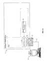
- FIG. 1Ashows a block diagram of a system including a host computer connected to a storage peripheral, in which embodiments of the invention may be practiced.
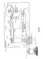
- FIG. 1Bshows a block diagram of a system including a host computer connected to a disk drive, in which embodiments of the invention may be practiced.
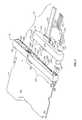
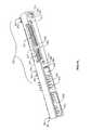
- FIG. 2shows a perspective view of a cable connector for mating to a PCB connector connected to a PCB, according to one embodiment of the invention.
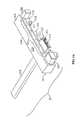
- FIG. 3Ashows a perspective view of a cable connector having a first blade-receiving portion that includes a first electrical contact arrangement configured for data signals in accordance with a SATA standard, according to one embodiment of the invention.
- FIG. 3Bshows a perspective view of a cable connector having a first blade-receiving portion configured for data signals in accordance with the SATA standard and a second blade-receiving portion configured for power signals in accordance with the SATA standard, according to one embodiment of the invention.
- FIG. 3Cshows a perspective view of a cable connector having guide arms that are approximately oval shaped, according to one embodiment of the invention.
- FIG. 4Ashows a perspective view of another embodiment of a cable connector configured for power signals in accordance with the SATA standard, according to one embodiment of the invention.
- FIG. 4Bshows a perspective view of another embodiment of a cable connector configured for data signals in accordance with the SATA standard, according to one embodiment of the invention.
- FIG. 4Cshows a perspective view of another embodiment of a cable connector configured for data signals in accordance with the SATA standard, according to one embodiment of the invention.
- FIG. 4Dshows a perspective view of another embodiment of a cable connector configured for power signals in accordance with the SATA standard, according to one embodiment of the invention.
- FIG. 4Eshows a perspective view of another embodiment of a cable connector configured for power signals in accordance with the SATA standard, according to one embodiment of the invention.
- FIG. 4Fshows a perspective view of another embodiment of a cable connector configured for both data and power signals in accordance with the SATA standard, according to one embodiment of the invention.
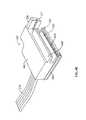
- FIG. 5Ashows a more detailed perspective view of the PCB connector of FIG. 2, according to one embodiment of the invention.
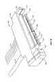
- FIG. 5Bshows a perspective view of a PCB connector having guide arm receiving cavities that are approximately oval shaped, according to one embodiment of the invention.
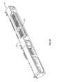
- FIG. 5Cshows a perspective view of another embodiment of the PCB connector, according to one embodiment of the invention.
- FIG. 6Ais a schematic diagram showing a pre-grounding configuration wherein both the data blade-receiving portion and the power blade-receiving portion of the cable connector are configured for pre-grounding to the PCB connector, according to one embodiment of the invention.
- FIG. 6Bis a schematic diagram showing a pre-grounding configuration wherein the data blade-receiving portion is not present and the power blade-receiving portion of the cable connector is configured for pre-grounding to the PCB connector, according to one embodiment of the invention.
- FIG. 6Cis a schematic diagram showing a pre-grounding configuration wherein the power blade-receiving portion is not present and the data blade-receiving portion of the cable connector is configured for pre-grounding to the PCB connector, according to one embodiment of the invention.
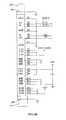
- FIG. 6Dshows a layout of the data and power signal contacts of the data and power blade connectors of the PCB connector onto the PCB and further shows grounding tabs of the guide arm receiving cavities coupled to ground on the PCB, according to one embodiment of the invention.
- FIG. 1Ashows a block diagram of a system including a host computer 12 connected to a storage peripheral 8 , in which embodiments of the invention may be practiced.
- the storage peripheral 8comprises a controller 26 having a Serial ATA (SATA) interface (not shown) connected to a SATA PCB connector 24 .
- the storage peripheral 8further includes a semiconductor memory 28 for data storage and retrieval.
- the controller 26 , semiconductor memory 28 , and SATA PCB connector 24are preferably mounted on a printed circuit board (PCB) 13 .
- the storage peripheral 8is connectable to a host computer 12 for receiving commands and data over a SATA cable 70 having a SATA cable connector 22 .
- storage peripheral 8may emulate a disk drive while communicating with the host computer 12 using a SATA protocol.
- Semiconductor memory 28may be a Flash memory system for providing non-volatile storage. In another embodiment, semiconductor memory 28 may be a large DRAM array suitable for caching data in a high performance system.
- FIG. 1Bshows a block diagram of a system including a host computer 12 ′ connected to a disk drive 10 , in which embodiments of the invention may be practiced.
- the disk drive 10acts as the storage peripheral.
- the disk drive 10includes a head disk assembly (HDA) 17 having a disk 18 and a transducer head 20 actuated radially over the disk.
- the disk drive 10further includes a disk control system 25 , which may include a SATA interface (not shown), and a serial ATA (SATA) PCB connector 24 ′.
- the disk control system 25responds to disk-drive commands and accesses data storage locations on the disk 18 through the transducer head 20 .
- the SATA PCB connector 24 ′couples the disk control system 25 to the host computer 12 ′ when the disk drive 10 is connected to the host computer 12 ′ via the SATA cable 70 ′ and the SATA cable connector 22 ′.
- the HDA 17 of disk drive 10further includes a spindle motor 52 for rotating the disk 18 and a voice coil motor (VCM) 54 for actuating the transducer head 20 radially over the disk 18 .
- a servo controller 56generates the appropriate control signals applied to the spindle motor 52 and the VCM 54 in response to commands received from the disk control system 25 .
- the disk control system 25transmits user data received from the host computer 12 ′ to a read/write channel 58 .
- the read/write channel 58performs appropriate encoding of the user data to generate write data 60 written to the disk 18 .
- the write data 60modulates the operation of a preamp 62 to generate a write signal 64 , applied to the head 20 in order to write magnetic transitions onto the surface of the disk 18 .
- the head 20detects the magnetic transitions representing the recorded data to generate a read signal 66 , which is amplified by the preamp 62 to generate a read signal 68 applied to the read/write channel 58 .
- the read/write channel 58demodulates the read signal 68 into user data transmitted to the host computer 12 ′ via disk control system 25 after correcting errors.
- the disk drive 10communicates with the host computer 12 ′ over a SATA cable 70 ′ that includes a SATA cable connector 22 ′ connected to the SATA PCB connector 24 ′ using a communication protocol defined by an industry standard such as the Serial ATA standard 1.0.
- the disk drivemay communicate with the host computer using an industry standard known as Serial Attached SCSI (SAS), which contemplates using cabling and circuitry originally defined in the SATA standard.
- SASSerial Attached SCSI
- the disk 18 , spindle motor 52 , VCM 54 , preamp 62 , and related hardwaremay be integrated into the HDA 17 .
- the disk control system 25 , SATA PCB connector 24 ′, semiconductor memory 28 ′, servo controller 56 , read/write channel 58 , and related electronicsmay be mounted on a printed circuit board (PCB) 13 ′.
- the disk control system 25generally includes circuitry and processors that control the HDA 17 and that provide an intelligent control interface between the host computer 12 ′ and the HDA for execution of disk-drive commands.
- the disk control system 25may have an internal microprocessor and nonvolatile memory for implementing the techniques of the invention.
- the semiconductor memory 28 ′may have nonvolatile memory and volatile random access memory (RAM).
- SATA cable connectors 22 , 22 ′SATA PCB connectors 24 , 24 ′ connected to PCBs 13 , 13 ′, SATA cables 70 , 70 ′, etc. It should be appreciated that the following description of SATA cable connectors, SATA PCB connectors, and SATA cables is applicable to either of the system environments of FIGS. 1A and 1B for a storage peripheral 8 or a disk drive 10 , respectively, both of which have been previously described in detail, as well as other types of system environments.
- SATA PCB connectors 24can similarly be connected to PCBs associated with a host computer or back-plane such that SATA cable connectors 22 can be connected to these PCB connectors and an interface can be provided at the host computer or back-plane end.
- FIG. 2shows a perspective view of a cable connector 22 for mating to a PCB connector 24 connected to a PCB 13
- FIG. 3Ashows another perspective view of the cable connector 22 having a first blade-receiving portion 212 that includes a first electrical contact arrangement 213 configured in accordance with a SATA standard.
- the first electrical contact arrangement 213 of the first blade-receiving portion 212is configured to mate with a first blade connector 206 of the PCB connector having a second electrical contact arrangement (not shown) also in accordance with the SATA standard.
- the cable connector 22includes a first blade-receiving portion 212 for enclosing the first electrical contact arrangement 213 , a housing 210 for supporting the first blade-receiving portion 212 , and at least one guide arm 220 that is integrally formed with the housing.
- a pair of laterally-opposed guide arms 220are integrally formed with the housing.
- a connector-support gap 230is formed in the housing 210 for receiving a second blade-receiving portion 225 .
- the housing 210has a cable entrance end 214 and a mating end 216 .
- At least one guide arm 220projects from the mating end 216 of the housing 210 and is disposed outside of and is separate from the first blade-receiving portion 212 . Further, in one embodiment, a pair of laterally-opposed guide arms 220 project from the mating end 216 of the housing 210 and are disposed outside of and are separate from the first blade-receiving portion 212 .
- a first shielded cable 272 having a first plurality of conductors configured in accordance with the SATA standardmay be connected to the first blade-receiving portion 212 .
- the first plurality of conductorsare connected to the first electrical contact arrangement of the first blade-receiving portion 212 .
- the combination of the cable connector 22 including the first blade-receiving portion 212 and the first shielded cable 272 connected theretomay be referred to as cable assembly 23 .
- the housing 210 of the cable connector 22is approximately U-shaped and has the connector-support gap 230 formed therein.
- the pair of laterally-opposed guide arms 220project from the mating end 216 of the housing 210 and are disposed outside of and are separate from the first blade-receiving portion 212 and the connector-support gap 230 .
- the housing 210includes a guide slot 217 in one of two opposite sidewalls 218 of the housing that aids in defining the connector-support gap 230 . Further, the top portion 219 of the housing may optionally have rectangular recesses 221 .
- the first electrical contact arrangement 213 of the first blade-receiving portion 212is configured for data signals in accordance with the SATA standard and is particularly configured to mate with the first blade connector 206 of the PCB connector 24 having a second electrical contact arrangement (not shown) also configured for data signals in accordance with the SATA standard.
- the first shielded cable 272 having a plurality of conductorsis configured for data signals in accordance with the SATA standard and is coupled to the data blade-receiving portion 212 .
- the plurality of conductors of the first shielded cable 272are connected to the data electrical contact arrangement 213 of the data blade-receiving portion 212 .
- the data blade-receiving portion 212includes a generally oblong rectangular housing 223 for enclosing the data electrical contact arrangement 213 configured in accordance with the SATA standard. At one end, the data blade-receiving portion 212 includes an L-shaped opening 225 for receipt of the corresponding L-shaped data blade connector 206 of the PCB connector 24 which has a mating data electrical contact arrangement configured in accordance with the SATA standard such that the data blade connector 206 properly mates with the data electrical contact arrangement 213 of the data blade-receiving portion 212 .
- the data blade-receiving portion 212receives the shielded cable 272 having a plurality of conductors configured for data signals in accordance with the SATA standard and the plurality of conductors are connected to the data electrical contact arrangement 213 inside the housing 223 of the data blade-receiving portion 212 .
- the data blade-receiving portion 212includes a side guide rail 227 to mate with the PCB connector 24 , as will be discussed in detail later. Also, the data blade-receiving portion 212 further includes a side guide slot 229 for receipt of a guide rail 236 of the second blade-receiving portion 225 , as will be discussed.
- the data blade-receiving portion 212may be integrally molded with the housing 210 .
- the first electrical contact arrangement of the first blade-receiving portionmay be configured for power signals in accordance with the SATA standard and would instead mate with a blade connector of the PCB connector likewise having an electrical contact arrangement configured for power signals in accordance with the SATA standard.
- the first shielded cable having a plurality of conductorswould be configured for power signals in accordance with the SATA standard. The plurality of conductors of the first shielded cable would connected to the power electrical contact arrangement of the power blade-receiving portion.
- FIG. 4Ashows an alternative embodiment of a cable connector 422 including a first blade-receiving portion 412 having a first electrical contact arrangement 413 configured for power signals in accordance with the SATA standard and which is configured to mate with a blade connector of a PCB connector likewise having an electrical contact arrangement configured for power signals in accordance with the SATA standard.
- the first shielded cable 474has a plurality of conductors configured for power signals in accordance with the SATA standard. The plurality of conductors of the first shielded cable 474 are connected to the power electrical contact arrangement 413 of the power blade-receiving portion 412 .
- the combination of the power cable connector 422 including the first blade-receiving portion 412 having the first electrical contact arrangement 413 configured for power signals and the first shielded cable 474 configured for power signals connected theretomay be referred to as cable assembly 423 .
- the blade-receiving portion configured for power signals in accordance with the SATA standardwill be discussed in detail later.
- FIG. 2shows a second blade-receiving portion 225
- a connector-support gap 230is formed in the housing 210 for receiving a second blade-receiving portion 225 .
- the second blade-receiving portion 225supports a third electrical contact arrangement 232 to mate with a second blade connector 228 having a fourth electrical contact arrangement (not shown) in accordance with the SATA standard.
- the third electrical contact arrangement 232is configured for power signals in accordance with the SATA standard and is configured to mate with the second blade connector 228 of the PCB connector 24 having a fourth electrical contact arrangement (not shown) also configured for power signals in accordance with the SATA standard.
- the cable connector 22includes a second blade-receiving portion 225 for enclosing the power electrical contact arrangement 232 .
- a shielded cable 274 having a plurality of conductors configured for power signals in accordance with the SATA standardis coupled to the power blade-receiving portion 225 and the plurality of conductors are connected to the power electrical contact arrangement 232 of the power blade-receiving portion 225 inside the power blade-receiving portion.
- the combination of the cable connector 22 including the data and power blade-receiving portions 212 , 225 and their respective first and second shielded cables 272 , 274 (i.e. data and power shielded cables) connected thereto,may be referred to as cable assembly 23 .
- the first electrical contact arrangement 213 of the first blade-receiving portion 212 and the first shielded cable 272may be configured for data signals in accordance with the SATA standard to mate with the first blade connector 206 of the PCB connector 24 having a second electrical contact arrangement similarly configured for data signals in accordance with the SATA standard and the third electrical contact arrangement 232 of the second blade-receiving portion 225 and the second shielded cable 274 may be configured for power signals in accordance with the SATA standard to mate with the second blade connector 228 of the PCB connector 24 having a fourth electrical contact arrangement similarly configured for power signals in accordance with the SATA standard.
- the data blade-receiving portion 212mates with the data blade connector 206 of the PCB connector 24 and the power blade-receiving portion 225 mates with the power blade connector 228 of the PCB connector 24 , respectively.
- the power blade-receiving portion 225includes a generally rectangular housing 233 for enclosing the power electrical contact arrangement 232 configured in accordance with the SATA standard.
- the power blade-receiving portion 225includes an L-shaped opening 235 for receipt of the corresponding L-shaped power blade connector 228 of the PCB connector 24 , which has a mating power electrical contact arrangement configured in accordance with the SATA standard, such that the power blade connector 228 of the PCB connector 24 properly mates with the power electrical contact arrangement 232 of the power blade-receiving portion 225 .
- the power blade-receiving portion 225receives shielded cable 274 having a plurality of conductors configured for power signals in accordance with the SATA standard and the plurality of conductors are connected to the power electrical contact arrangement 232 inside the housing 233 of the power blade-receiving portion 225 .
- the power blade-receiving portion 225includes a pair of side guide rails.
- a first guide rail 234mates with the opposed guide slot 217 of the housing 210 such that the power blade-receiving portion 225 interlocks with the housing 210 of the cable connector 22 and a second slender rectangular guide rail 236 mates with the side guide slot 229 of the data blade-receiving portion 212 and interlocks with the data blade-receiving portion.
- an integral cable connector 22is formed.
- the data blade-receiving portion 212 and the power blade-receiving portion 225may be integrally molded with the housing 210 .
- the guide arms 220project from the mating end 216 of the housing 210 of the cable connector 22 and are disposed outside of and are separate from the first blade-receiving portion 212 and the connector-support gap 230 .
- the guide arms 220are approximately rectangularly shaped as particularly shown in FIG. 3 B. Further, as shown in FIG. 3B, the guide arms 220 may be differently sized.
- each of the guide arms 220may include a conductive contact 237 such as a grounding clip.
- the conductive contactsmay provide pre-grounding functionality for one of the data or power blade-receiving portions or both.
- one of the conductive contacts 237 of a one of the guide armsmay be coupled to a ground conductor of the first shielded cable 272 (e.g. configured for data signals) and the other conductive contact 237 of the other guide arm may be coupled to a ground conductor of the second shielded cable 274 (e.g. configured for power signals), as will be discussed.
- Various other grounding configurations for pre-grounding and the dissipation of electro-static discharge (ESD)will also be discussed.
- the housing 210 and the guide arms 220may be made from a conductive plastic material such that the cable connector 22 is conductive.
- the plastic materialmay include a conductive filler material. This may be referred to as the conductive cable connector embodiment.
- the guide arms 221may be approximately oval shaped. Again, as previously described, the guide arms 221 may be differently sized. Further, although not shown in FIG. 3C, each oval shaped guide arm 221 may also include a conductive contact such as a grounding clip.
- a cable connector 448 utilized only for data signal connectionis shown.
- the data cable connector 448may include a housing 452 for supporting a data blade-receiving portion 212 having an electrical contact arrangement 213 configured for data signals in accordance with the SATA standard.
- the data blade-receiving portion 212may be integrally molded with the housing 452 .
- the data cable connector 448only includes one guide arm 220 .
- the guide arm 220is integrally formed with the housing 452 and projects from the mating end of the housing and is disposed outside of and is separate from the data blade-receiving portion 212 .
- the guide armincludes a conductive contact 237 , such as a grounding clip.
- the housing 452 and the guide arm 220may be made from a conductive plastic material.
- the data electrical contact arrangement 213 of the data blade-receiving portion 212is configured to mate with the data blade connector 206 of the PCB connector 24 having an electrical contact arrangement also configured for data signals in accordance with the SATA standard.
- a shielded cable 272 having a plurality of conductors configured for data signals in accordance with the SATA standardis coupled to the data blade-receiving portion 212 and the plurality of conductors are connected to the data electrical contact arrangement 213 of the data blade-receiving portion 212 inside the data blade-receiving portion.
- the conductive contact 237 of the guide arm 220may be coupled to a ground conductor of the shielded data cable 272 (e.g. configured for data signals) for pre-grounding.
- the rectangular guide arm 220is suitably formed for receipt by a guide arm receiving cavity of the PCB connector 24 , as will be discussed.
- the SATA standard utilizedmay be a SAS standard.
- housing 452may include a side guide slot 454 for mating with a rectangular guide rail of another separate power cable connector, as will be discussed.
- the data cable connector 448includes a second guide arm 458 that is shaped as an elongated tongue.
- the second elongated tongue guide arm 458is suitably formed for receipt by a guide arm receiving cavity of the PCB connector 24 that is shaped as elongated slot, as will be discussed.
- FIG. 4Dshows a cable connector 460 that is utilized only for power signal connection.
- the power cable connector 460may include a housing 462 for supporting a power blade-receiving portion 225 having an electrical contact arrangement 232 configured for power signals in accordance with the SATA standard.
- the power blade-receiving portion 225may be integrally molded with the housing 462 .
- the power cable connector 460only includes one guide arm 220 .
- the guide arm 220is integrally formed with the housing 462 and projects from the mating end of the housing and is disposed outside of and is separate from the power blade-receiving portion 225 .
- the guide armincludes a conductive contact 237 , such as a grounding clip.
- the housing 462 and the guide arm 220may be made from a conductive plastic material.
- the power electrical contact arrangement 232 of the power blade-receiving portion 225is configured to mate with the power blade connector 228 of the PCB connector 24 having an electrical contact arrangement also configured for power signals in accordance with the SATA standard.
- a shielded cable 274 having a plurality of conductors configured for power signals in accordance with the SATA standardis coupled to the power blade-receiving portion 225 and the plurality of conductors are connected to the power electrical contact arrangement 232 of the power blade-receiving portion 225 inside the power blade-receiving portion.
- the conductive contact 237 of the guide arm 220may be coupled to a ground conductor of the shielded power cable 274 (e.g. configured for power signals) for pre-grounding.
- the rectangular guide arm 220is suitably formed for receipt by a guide arm receiving cavity of the PCB connector 24 , as will be discussed.
- the SATA standard utilizedmay be a SAS standard.
- housing 462may include a side guide rail 464 for mating with side guide slot 454 of the data cable connector 448 .
- the power cable connector 460includes a second guide arm 468 that is shaped as an elongated tongue.
- the second elongated tongue guide arm 468is suitably formed for receipt by a guide arm receiving cavity of the PCB connector 24 that is shaped as elongated slot, as will be discussed.
- FIG. 4Fshows a combined cable connector 480 that is utilized for both data and power signal connection and is a combination of the data cable connector 448 and the power cable connector 460 , previously discussed.
- the combined cable connector 480may be formed by the combination of the power and data cable connectors 460 , 448 , previously discussed, by the side guide rail 464 of the power cable connector mating with the side guide slot 454 of the data cable connector 448 to form the combined cable connector 480 .
- the combined cable connector 480may be formed by the integral molding of the previously described power and data cable connectors 460 , 448 , respectively.
- the combined cable connector 480may include a housing 482 for supporting both the data blade-receiving portion 212 having an electrical contact arrangement 213 configured for data signals in accordance with the SATA standard and a power blade-receiving portion 225 having an electrical contact arrangement 232 configured for power signals in accordance with the SATA standard.
- a pair of laterally-opposed guide arms 220are integrally formed with the housing 482 and project from the mating end of the housing and are disposed outside of and are separate from both the data and power blade-receiving portions 212 , 225 .
- the guide armseach include a conductive contact 237 , such as a grounding clip.
- the housing 482 and the guide arms 220may be made from a conductive plastic material.
- the data electrical contact arrangement 213 of the data blade-receiving portion 212is configured to mate with the data blade connector 206 of the PCB connector 24 having an electrical contact arrangement also configured for data signals in accordance with the SATA standard.
- a shielded cable 272 having a plurality of conductors configured for data signals in accordance with the SATA standardis coupled to the data blade-receiving portion 212 and the plurality of conductors are connected to the data electrical contact arrangement 213 of the data blade-receiving portion 212 inside the data blade-receiving portion.
- the conductive contact 237 of the guide arm 220may be coupled to a ground conductor of the shielded data cable 272 (e.g. configured for data signals) for pre-grounding.
- the power electrical contact arrangement 232 of the power blade-receiving portion 225is configured to mate with the power blade connector 228 of the PCB connector 24 having an electrical contact arrangement also configured for power signals in accordance with the SATA standard.
- a shielded cable 274 having a plurality of conductors configured for power signals in accordance with the SATA standardis coupled to the power blade-receiving portion 225 and the plurality of conductors are connected to the power electrical contact arrangement 232 of the power blade-receiving portion 225 inside the power blade-receiving portion.
- the conductive contact 237 of the guide arm 220may be coupled to a ground conductor of the shielded power cable 274 (e.g. configured for power signals) for pre-grounding.
- the rectangular guide arms 220are suitably formed for receipt by guide arm receiving cavities of the PCB connector 24 , as will be discussed.
- the SATA standard utilizedmay be a SAS standard.
- the combined cable connector 480includes a second guide arm 488 that is shaped as an elongated tongue.
- the second elongated tongue guide arm 488is suitably formed for receipt by a guide arm receiving cavity of the PCB connector 24 that is shaped as elongated slot, as will be discussed.
- FIG. 5Ashows a more detailed perspective view of the PCB connector 24 of FIG. 2 .
- the PCB connector 24is mounted to a printed circuit board (PCB) 13 .
- Mounting brackets 280 of the PCB connector 24support the PCB 13 and mounting posts 281 extend from the mounting brackets 280 via through-holes of the PCB creating an interference fit to secure the PCB connector 24 to the PCB 13 .
- many pins of the various connectorsare also fixed to the PCB 13 further securing the PCB connector 24 to the PCB 13 .
- the PCB connector 24includes a housing 270 having a SATA section 265 , a legacy Integrated Drive Electronics (IDE) power section receptacle 266 , and a user section receptacle 268 .
- the housing 270 of the PCB connector 24may only include the SATA section 265 and the legacy IDE power section receptacle 266 and the user section receptacle 268 may not be present.
- the PCB connector 24includes a first blade connector 206 for supporting a first electrical contact arrangement 209 in accordance with a SATA standard, a second blade connector 228 for supporting a second electrical contact arrangement 231 in accordance with the SATA standard, and the housing 270 encloses the first and second blade connectors and the supported electrical contact arrangements.
- the electrical contacts of the electrical contact arrangements of the blade connectors 206 and 228are mounted to the PCB 13 via through-holes of the PCB 13 , for example.
- other methods of mounting the electrical contactscould be used, such as surface mount technologies.
- the housing 270includes a pair of opposed guide slots 271 in each one of two opposite sidewalls of the housing 270 that define a cable connector receiving area 252 around the first and second blade connectors 206 and 228 for the receipt of at least one cable connector, respectively.
- the cable connector receiving area 252is in accordance with the SATA standard.
- the first electrical contact arrangement 209 of the first L-shaped blade connector 206is configured for data signals in accordance with the SATA standard and a second electrical contact arrangement 231 of the second L-shaped blade connector 228 is configured for power signals in accordance with the SATA standard.
- the housing 270 of the PCB connector 24includes at least one guide arm receiving cavity 254 that is integrally formed with the housing 270 and that is disposed outside of the cable connector receiving area 252 .
- the housing 270includes a pair of laterally-opposed guide arm receiving cavities 254 that are integrally formed with the housing 270 and that are disposed outside the cable connector receiving area 252 .
- the guide arm receiving cavities 254are adapted for the receipt of the guide arms 220 from the mating cable connector 22 .
- the guide arm receiving cavities 254are adapted for the receipt of guide arms 220 from the other alternative embodiments of the mating cable connector 22 such as power signal only cable connector 422 , data signal only cable connector 448 , power signal only cable connector 460 , and combined data and power signal cable connector 480 .
- these connectorsboth have two laterally-opposed guide arms both of which mate to the guide arm receiving cavities 254 .
- these connectorseach have only one guide arm for mating with one of the respective guide arm receiving cavities 254 .
- the guide arm receiving cavities 254are approximately rectangularly shaped and may be differently sized, as particularly shown in FIG. 5 A.
- the guide arm receiving cavities 354may be approximately oval shaped and may also be differently sized.
- the housing 270 of the PCB connector 24may further have an elongated slot 292 for the receipt of the second guide arms 458 , 468 , and 488 of the data signal only cable connector 448 , the power signal only cable connector 460 , and the combined data and power signal cable connector 480 , respectively, all of which are shaped as elongated tongues, as previously discussed.
- the housing 270further includes substantially thickened strengthening walls 260 disposed between the cable connector receiving area 252 and the guide arm receiving cavities 254 making the PCB connector 24 very robust.
- embodiments of the present inventionrelate to a more robust SATA compliant cable connector 22 and SATA compliant PCB connector 24 that avoid many of the breakage problems associated with these present devices.
- This further applies to the other disclosed alternative embodiments of cable connector 22such as power signal only cable connector 422 , data signal only cable connector 448 , power signal only cable connector 460 , and combined data and power signal cable connector 480 .
- one or both of the data blade-receiving portion 212 and/or the power blade-receiving portion 225mate with their respective data blade connector 206 and/or power blade connector 228 of the SATA defined cable connector receiving area 252 , in which one or both of guide rails 227 , 234 of the data blade-receiving portion 212 and/or the power blade-receiving portion 225 mate with one or both of the guide slots 271 of the cable connector receiving area, respectively.
- the housing 210 of the cable connector 22rigidly contains one or both of the data blade-receiving portion 212 and/or the power blade-receiving portion 225 , and when the cable connector 22 is mated to the PCB connector 24 , the pair of laterally-opposed guide arms 220 of the cable connector 22 mate with the pair of laterally-opposed guide arm cavities 254 of the PCB connector 24 such that the blade-receiving portions 212 , 225 of the cable connector mate with the blade connectors 206 , 228 of the PCB connector in an aligned and firm manner such that the common problems associated with the breakage of the blade connectors is avoided.
- cable connector 22such as power signal only cable connector 422 , data signal only cable connector 448 , power signal only cable connector 460 , and combined data and power signal cable connector 480 .
- data signal only cable connector 448 and power signal only cable connector 460only one guide arm mates with a respective guide arm receiving cavity.
- the guide arms 220 mating with the guide arm receiving cavities 254align the blade-receiving portions 212 , 225 of the various embodiments of the disclosed cable connectors with the blade connectors 206 , 228 of the PCB connector 24 . Moreover, much of the forces associated with the blade-receiving portions mating to the blade connectors are transferred to the guide arms 220 , the guide arm receiving cavities 254 , and the substantially thickened strengthening walls 260 of the strengthened housing 270 of the PCB connector 24 . This further reduces the forces applied to the blade connectors to further avoid breakage.
- the housing 270 of the PCB connector 24may further include a legacy Integrated Drive Electronics (IDE) power section receptacle 266 , and a user section receptacle 268 .
- the legacy IDE power section receptacle 266includes various legacy pins 267 , such as 12 V and 5 V power pins and associated ground pins that are connected to the PCB 13 , and that can be used for powering a storage peripheral, such as a disk drive, instead of utilizing the SATA power blade connector.
- the housing 270 of the PCB connector 24may further include a user section receptacle 268 that includes a plurality of square pins 269 that are utilized to command a storage peripheral, such as a disk drive, to operate in a plurality of different modes.
- a storage peripheralsuch as a disk drive
- the user section receptacle 268is often used in disk drive testing.
- the square pins 269 of the user section receptacle 228are connected to the PCB 13 .
- Embodiments of the present invention for the various cable connectors and the PCB connector 24also provide for pre-grounding (i.e. the dissipation of electro-static discharge (ESD)).
- ESDelectro-static discharge
- one or both of the guide arms 220 of the various disclosed cable connectorsmay include a conductive contact 237 such as a grounding clip.
- the grounding contacts 237 of the guide armsmay be coupled to ground conductors of the data and power shielded cables 272 , 275 connected inside of the data and power blade-receiving portions 212 , 225 , respectively, in order to effectuate various grounding configurations for pre-grounding.
- one or both of guide arm receiving cavities 254may include a conductive surface such as a grounding tab 264 (e.g. a metal grounding tab). Each grounding tab 264 is coupled to ground on the PCB 13 by a ground post 263 , respectively.
- the rectangular or oval shaped guide arm receiving cavitiesmay include conductive surfaces for mating with a corresponding grounding contact of a corresponding rectangular or oval shaped guide arm.
- the conductive contacts 237 of the guide arms 220will engage the grounding tabs 264 of the guide arm receiving cavities 254 providing pre-grounding to either one or both of the data and/or power blade-receiving portions 212 , 225 before they engage with the corresponding data and/or power blade connectors 206 , 228 .
- This of courseapplies to the other disclosed alternative embodiments of cable connector 22 such as power signal only cable connector 422 , data signal only cable connector 448 , power signal only cable connector 460 , and combined data and power signal cable connector 480 . Specific examples of this, related to the cable connector 22 as an example, will now be described.
- the housing 210 and the guide arms 220may be made from a conductive plastic material such that the cable connector 22 is conductive.
- the housing 270 of the PCB connector 24may also be made from a conductive plastic material such that the PCB connector 24 is also conductive and can be grounded.
- the guide arms 220will first engage the guide arm receiving cavities 254 providing pre-grounding to either one or both of the data and/or power blade-receiving portions 212 , 225 before they engage with the corresponding data and/or power blade connectors 206 , 228 .
- Thisalso applies to the other disclosed alternative embodiments of cable connector 22 such as power signal only cable connector 422 , data signal only cable connector 448 , power signal only cable connector 460 , and combined data and power signal cable connector 480 .
- FIG. 6Ais a schematic diagram showing a pre-grounding configuration wherein both the data blade-receiving portion 212 and the power blade-receiving portion 225 of the cable connector 22 are configured for pre-grounding to the PCB connector 24 .
- a plurality of data SATA signal conductors 602 of the data SATA shielded cable 272are shown, which are located in the data blade-receiving portion 212 and are connected to the data electrical contact arrangement 213 .
- a ground conductor 604is directly coupled to a grounding contact 237 (e.g.
- a ground clipof one of the guide arms 220 for pre-grounding (i.e. electro-static discharge (ESD)). This is shown as line 606 (ESD- 1 ).
- a plurality of power SATA signal conductors 610 of the power SATA shielded cable 274are shown, which are located in the power blade-receiving portion 225 and are connected to the power electrical contact arrangement 232 .
- a ground conductor 612is directly coupled to a grounding contact 237 (e.g. a ground clip) of one of the guide arms 220 for pre-grounding (i.e. electro-static discharge (ESD)). This is shown as line 608 (ESD- 1 ).
- the grounding contacts 237 of the guide arms 220will engage the grounding tabs 264 of the guide arm receiving cavities 254 providing pre-grounding to the data and power blade-receiving portions 212 , 225 before they engage with the corresponding data and power blade connectors 206 , 228 .
- the ground conductorsmay just be coupled to the guide arms to provide pre-grounding. Further, it should be appreciated that this grounding configuration for pre-grounding is also applicable to other disclosed alternative embodiments of cable connectors such as the combined data and power signal cable connector 480 .
- FIG. 6Bis a schematic diagram showing a pre-grounding configuration wherein the data blade-receiving portion is not present and the power blade-receiving portion 225 of the cable connector 22 is configured for pre-grounding to the PCB connector 24 .
- a plurality of power SATA signal conductors 610 of the power SATA shielded cable 274are shown, which are located in the power blade-receiving portion 225 and are connected to the power electrical contact arrangement 232 .
- a first ground conductor 611is directly coupled to a grounding contact 237 (e.g. a ground clip) of one of the guide arms 220 for pre-grounding (i.e.
- ESDelectro-static discharge
- line 612ESD- 1
- a second ground conductor 613is directly coupled to a grounding contact 237 (e.g. a ground clip) of one of the guide arms 220 for pre-grounding (i.e. electro-static discharge (ESD)), which is shown as line 614 (ESD- 2 ).
- ESDelectro-static discharge
- line 614ESD- 2
- the grounding contacts 237 of the guide arms 220will engage the grounding tabs 264 of the guide arm receiving cavities 254 providing pre-grounding for the power blade-receiving portion 225 before it engages with the corresponding power blade connector 228 .
- the ground conductorsmay just be coupled to the guide arms to provide pre-grounding. Further, it should be appreciated that this grounding configuration for pre-grounding is also applicable to other disclosed alternative embodiments of cable connectors such as the power signal only cable connector 422 and the power signal only cable connector 460 .
- FIG. 6Cis a schematic diagram showing a pre-grounding configuration wherein the power blade-receiving portion is not present and the data blade-receiving portion 212 of the cable connector 22 is configured for pre-grounding to the PCB connector 24 .
- a plurality of data SATA signal conductors 602 of the data SATA shielded cable 272are shown, which are located in the data blade-receiving portion 212 and are connected to the data electrical contact arrangement 213 .
- a first ground conductor 621is directly coupled to a grounding contact 237 (e.g. a ground clip) of one of the guide arms 220 for pre-grounding (i.e.
- ESDelectro-static discharge
- line 622ESD- 1
- a second ground conductor 623is directly coupled to a grounding contact 237 (e.g. a ground clip) of one of the guide arms 220 for pre-grounding (i.e. electrostatic discharge (ESD)), which is shown as line 624 (ESD- 2 ).
- ESDelectrostatic discharge
- line 624ESD- 2
- the grounding contacts 237 of the guide arms 220will engage the grounding tabs 264 of the guide arm receiving cavities 254 providing pre-grounding for the data blade-receiving portion 225 before it engages with the corresponding data blade connector 206 .
- the ground conductorsmay just be coupled to the guide arms to provide pre-grounding. Further, it should be appreciated that this grounding configuration for pre-grounding is also applicable to other disclosed alternative embodiments of cable connectors such as the data signal only cable connector 448 .
- FIG. 6Dshows the layout of the data and power signal contacts of the data and power blade connectors 206 , 228 of the PCB connector 24 onto the PCB 13 and further shows grounding tabs 264 of the guide arm receiving cavities 254 coupled to ground on PCB 13 .
- the grounding tabs 264could also be coupled to a ground at another location.
- the grounding tabscould be coupled to the grounded chassis of the disk drive.
Landscapes
- Details Of Connecting Devices For Male And Female Coupling (AREA)
Abstract
Description
Claims (23)
Priority Applications (1)
| Application Number | Priority Date | Filing Date | Title |
|---|---|---|---|
| US10/295,665US6832929B2 (en) | 2002-11-15 | 2002-11-15 | Robust serial advanced technology attachment (SATA) PCB connector |
Applications Claiming Priority (1)
| Application Number | Priority Date | Filing Date | Title |
|---|---|---|---|
| US10/295,665US6832929B2 (en) | 2002-11-15 | 2002-11-15 | Robust serial advanced technology attachment (SATA) PCB connector |
Publications (2)
| Publication Number | Publication Date |
|---|---|
| US20040097123A1 US20040097123A1 (en) | 2004-05-20 |
| US6832929B2true US6832929B2 (en) | 2004-12-21 |
Family
ID=32297270
Family Applications (1)
| Application Number | Title | Priority Date | Filing Date |
|---|---|---|---|
| US10/295,665Expired - LifetimeUS6832929B2 (en) | 2002-11-15 | 2002-11-15 | Robust serial advanced technology attachment (SATA) PCB connector |
Country Status (1)
| Country | Link |
|---|---|
| US (1) | US6832929B2 (en) |
Cited By (175)
| Publication number | Priority date | Publication date | Assignee | Title |
|---|---|---|---|---|
| US6957985B1 (en)* | 2004-06-29 | 2005-10-25 | Hon Hai Precision Ind. Co., Ltd. | Blind mating electrical connector |
| US20060057877A1 (en)* | 2004-09-14 | 2006-03-16 | Gill Mark A | Intermodule connection in communication system |
| USD550627S1 (en)* | 2005-10-21 | 2007-09-11 | Hon Hai Precision Ind. Co., Ltd. | Cable connector assembly |
| US20100087100A1 (en)* | 2007-02-23 | 2010-04-08 | Roland Tristan De Blieck | Electrical connector |
| US20100120283A1 (en)* | 2008-11-10 | 2010-05-13 | Hon Hai Precision Industry Co., Ltd. | Electrical connector having positioning posts defined on insulative base |
| US7778031B1 (en) | 2009-07-15 | 2010-08-17 | Teradyne, Inc. | Test slot cooling system for a storage device testing system |
| US7848106B2 (en) | 2008-04-17 | 2010-12-07 | Teradyne, Inc. | Temperature control within disk drive testing systems |
| US7890207B2 (en) | 2008-04-17 | 2011-02-15 | Teradyne, Inc. | Transferring storage devices within storage device testing systems |
| US7904211B2 (en) | 2008-04-17 | 2011-03-08 | Teradyne, Inc. | Dependent temperature control within disk drive testing systems |
| US7908029B2 (en) | 2008-06-03 | 2011-03-15 | Teradyne, Inc. | Processing storage devices |
| US7911778B2 (en) | 2008-04-17 | 2011-03-22 | Teradyne, Inc. | Vibration isolation within disk drive testing systems |
| US7929303B1 (en) | 2010-02-02 | 2011-04-19 | Teradyne, Inc. | Storage device testing system cooling |
| US7932734B2 (en) | 2009-07-15 | 2011-04-26 | Teradyne, Inc. | Individually heating storage devices in a testing system |
| US7940529B2 (en) | 2009-07-15 | 2011-05-10 | Teradyne, Inc. | Storage device temperature sensing |
| US7945424B2 (en) | 2008-04-17 | 2011-05-17 | Teradyne, Inc. | Disk drive emulator and method of use thereof |
| US7987018B2 (en) | 2008-04-17 | 2011-07-26 | Teradyne, Inc. | Transferring disk drives within disk drive testing systems |
| US7996174B2 (en) | 2007-12-18 | 2011-08-09 | Teradyne, Inc. | Disk drive testing |
| US8041449B2 (en) | 2008-04-17 | 2011-10-18 | Teradyne, Inc. | Bulk feeding disk drives to disk drive testing systems |
| US8102173B2 (en) | 2008-04-17 | 2012-01-24 | Teradyne, Inc. | Thermal control system for test slot of test rack for disk drive testing system with thermoelectric device and a cooling conduit |
| US8116079B2 (en) | 2009-07-15 | 2012-02-14 | Teradyne, Inc. | Storage device testing system cooling |
| US8238099B2 (en) | 2008-04-17 | 2012-08-07 | Teradyne, Inc. | Enclosed operating area for disk drive testing systems |
| US8405971B2 (en) | 2007-12-18 | 2013-03-26 | Teradyne, Inc. | Disk drive transport, clamping and testing |
| US8482915B2 (en) | 2008-04-17 | 2013-07-09 | Teradyne, Inc. | Temperature control within disk drive testing systems |
| US8547123B2 (en) | 2009-07-15 | 2013-10-01 | Teradyne, Inc. | Storage device testing system with a conductive heating assembly |
| US8616900B1 (en) | 2011-01-20 | 2013-12-31 | Western Digital Technologies, Inc. | Disk drive having a top cover with an electrical connector latch |
| US8628239B2 (en) | 2009-07-15 | 2014-01-14 | Teradyne, Inc. | Storage device temperature sensing |
| US8687349B2 (en) | 2010-07-21 | 2014-04-01 | Teradyne, Inc. | Bulk transfer of storage devices using manual loading |
| US8845368B1 (en)* | 2012-08-31 | 2014-09-30 | Amazon Technologies, Inc. | Electrical connectors |
| US8879188B1 (en) | 2010-08-23 | 2014-11-04 | Western Digital Technologies, Inc. | Disk drive employing fly height calibration tracks to account for magnetic entropy and thermal decay |
| US8891193B1 (en) | 2013-05-09 | 2014-11-18 | Western Digital Technologies, Inc. | Disk drive calibrating threshold and gain of touchdown sensor |
| US8891341B1 (en) | 2013-03-11 | 2014-11-18 | Western Digital Technologies, Inc. | Energy assisted magnetic recording disk drive using modulated laser light |
| US8902529B1 (en) | 2012-11-20 | 2014-12-02 | Western Digital Technologies, Inc. | Dual frequency crystal oscillator |
| US8902527B1 (en) | 2010-03-22 | 2014-12-02 | Western Digital Technologies, Inc. | Systems and methods for improving sequential data rate performance using sorted data zones |
| US8909889B1 (en) | 2011-10-10 | 2014-12-09 | Western Digital Technologies, Inc. | Method and apparatus for servicing host commands by a disk drive |
| US8908311B1 (en) | 2014-01-27 | 2014-12-09 | Western Digital Technologies, Inc. | Data storage device writing a multi-sector codeword in segments over multiple disk revolutions |
| US8914625B1 (en) | 2009-07-31 | 2014-12-16 | Western Digital Technologies, Inc. | Automatically configuring a web browser file when booting an operating system from a data storage device |
| US8922939B1 (en) | 2013-04-02 | 2014-12-30 | Western Digital Technologies, Inc. | Disk drive generating feed-forward fly height control based on temperature sensitive fly height sensor |
| US8937782B1 (en) | 2012-05-07 | 2015-01-20 | Western Digital Technologies, Inc. | Hard disk drive assembly including a NVSM to store configuration data for controlling disk drive operations |
| US8941941B1 (en) | 2013-02-28 | 2015-01-27 | Western Digital Technologies, Inc. | Disk drive calibrating touchdown sensor |
| US8947812B1 (en) | 2014-03-27 | 2015-02-03 | Western Digital Technologies, Inc. | Data storage device comprising equalizer filter and inter-track interference filter |
| US8949521B1 (en) | 2013-04-10 | 2015-02-03 | Western Digital Technologies, Inc. | Actuator prepositioning for disk drive |
| US8953269B1 (en) | 2014-07-18 | 2015-02-10 | Western Digital Technologies, Inc. | Management of data objects in a data object zone |
| US8953277B1 (en) | 2014-06-16 | 2015-02-10 | Western Digital Technologies, Inc. | Data storage device writing tracks on a disk with equal spacing |
| US8954664B1 (en) | 2010-10-01 | 2015-02-10 | Western Digital Technologies, Inc. | Writing metadata files on a disk |
| US8958167B1 (en) | 2013-12-23 | 2015-02-17 | Western Digital Technologies, Inc. | Detection of disk surface irregularities in data storage devices |
| US8959281B1 (en) | 2012-11-09 | 2015-02-17 | Western Digital Technologies, Inc. | Data management for a storage device |
| US8970978B1 (en) | 2012-10-22 | 2015-03-03 | Western Digital Technologies, Inc. | Disk drive detecting head touchdown by applying DC+AC control signal to fly height actuator |
| US8976633B1 (en) | 2014-04-15 | 2015-03-10 | Western Digital Technologies, Inc. | Data storage device calibrating fly height actuator based on laser power for heat assisted magnetic recording |
| US8988809B1 (en) | 2014-02-18 | 2015-03-24 | Western Digital (Fremont), Llc | Disk recording device for writing a radially coherent reference band by measuring relative timing offsets of reference bursts |
| US8988810B1 (en) | 2014-04-16 | 2015-03-24 | Western Digital Technologies, Inc. | Track measurement for data storage device |
| US8990493B1 (en) | 2011-06-30 | 2015-03-24 | Western Digital Technologies, Inc. | Method and apparatus for performing force unit access writes on a disk |
| US8996839B1 (en) | 2012-01-23 | 2015-03-31 | Western Digital Technologies, Inc. | Data storage device aligning partition to boundary of sector when partition offset correlates with offset of write commands |
| US9001456B2 (en) | 2010-08-31 | 2015-04-07 | Teradyne, Inc. | Engaging test slots |
| US9001453B1 (en) | 2014-07-18 | 2015-04-07 | Western Digital Technologies, Inc. | Data storage device calibrating fly height actuator based on read mode touchdown resistance of touchdown sensor |
| US9009358B1 (en) | 2008-09-23 | 2015-04-14 | Western Digital Technologies, Inc. | Configuring a data storage device with a parameter file interlocked with configuration code |
| US9013818B1 (en) | 2013-12-06 | 2015-04-21 | Western Digital Technologies, Inc. | Disk drive measuring reader/writer gap by measuring fractional clock cycle over disk radius |
| US9013821B1 (en) | 2014-06-10 | 2015-04-21 | Western Digital Technologies, Inc. | Data storage device employing one-dimensional and two-dimensional channels |
| US9021410B1 (en) | 2013-12-10 | 2015-04-28 | Western Technologies, Inc. | Electronic system with multi-cycle simulation coverage mechanism and method of operation thereof |
| US9025421B1 (en) | 2014-10-08 | 2015-05-05 | Western Digital Technologies, Inc. | Data storage device adjusting laser input power to compensate for temperature variations |
| US9025270B1 (en) | 2013-09-17 | 2015-05-05 | Western Digital Technologies, Inc. | Electronic system with current conservation mechanism and method of operation thereof |
| US9025267B1 (en) | 2014-06-09 | 2015-05-05 | Western Digital Technologies, Inc. | Data storage device using branch metric from adjacent track to compensate for inter-track interference |
| US9049471B2 (en) | 2001-10-17 | 2015-06-02 | Keen Personal Media, Inc. | Personal video recorder for inserting a stored advertisement into a displayed broadcast stream |
| US9047917B1 (en) | 2013-11-26 | 2015-06-02 | Western Digital Technologies, Inc. | Disk drive slider with sense amplifier for coupling to a preamp through a supply/bias line and a read signal line |
| US9053730B1 (en) | 2012-05-11 | 2015-06-09 | Western Digital Technologies, Inc. | Disk drive comprising extended range head proximity sensor |
| US9053749B1 (en) | 2013-03-15 | 2015-06-09 | Western Digital Technologies, Inc. | Disk drive comprising a per-drive and per-head fly height filter |
| US9060420B2 (en) | 2007-11-01 | 2015-06-16 | Western Digitial Technologies, Inc. | Method of manufacturing a double sided flex circuit for a disk drive wherein a first side lead provides an etching mask for a second side lead |
| US9064525B2 (en) | 2013-11-26 | 2015-06-23 | Western Digital Technologies, Inc. | Disk drive comprising laser transmission line optimized for heat assisted magnetic recording |
| US9064504B1 (en) | 2014-01-29 | 2015-06-23 | Western Digital Technologies, Inc. | Electronic system with media recovery mechanism and method of operation thereof |
| US9064542B1 (en) | 2013-04-08 | 2015-06-23 | Western Digital Technologies, Inc. | Scheduled load of heads to reduce lubricant migration on pole tip and decrease time to ready |
| US9063838B1 (en) | 2012-01-23 | 2015-06-23 | Western Digital Technologies, Inc. | Data storage device shifting data chunks of alignment zone relative to sector boundaries |
| US9070406B1 (en) | 2014-03-10 | 2015-06-30 | Western Digital Technologies, Inc. | Disk drive configuring one-dimensional and two-dimensional recording areas based on read element spacing |
| US9076474B1 (en) | 2014-12-23 | 2015-07-07 | Western Digital Technologies, Inc. | Data storage device attenuating thermal decay effect on fly height measurement |
| US9074941B1 (en) | 2013-03-14 | 2015-07-07 | Western Digital Technologies, Inc. | Systems and methods for measuring ambient and laser temperature in heat assisted magnetic recording |
| US9075714B1 (en) | 2014-05-13 | 2015-07-07 | Western Digital Technologies, Inc. | Electronic system with data management mechanism and method of operation thereof |
| US9082458B1 (en) | 2014-03-10 | 2015-07-14 | Western Digital Technologies, Inc. | Data storage device balancing and maximizing quality metric when configuring arial density of each disk surface |
| US9099134B1 (en) | 2015-01-27 | 2015-08-04 | Western Digital Technologies, Inc. | Data storage device employing multiple jog profiles for a butterfly written disk surface |
| US9099103B1 (en) | 2014-10-21 | 2015-08-04 | Western Digital Technologies, Inc. | Heat assisted magnetic recording withinterlaced high-power heated and low-power heated tracks |
| US9099144B1 (en) | 2013-10-11 | 2015-08-04 | Western Digital Technologies, Inc. | Disk drive evaluating laser performance for heat assisted magnetic recording |
| US9117479B1 (en) | 2014-09-24 | 2015-08-25 | Western Digital Technologies, Inc. | Data storage device calibrating laser write power for heat assisted magnetic recording |
| US9117463B1 (en) | 2014-06-23 | 2015-08-25 | Western Digital Technologies, Inc. | Data storage device erasing multiple adjacent data tracks to recover from inter-track interference |
| US9117489B1 (en) | 2014-02-18 | 2015-08-25 | Western Digital Technologies, Inc. | Data storage device screening heads by verifying defects after defect scan |
| US9123370B1 (en) | 2014-04-15 | 2015-09-01 | Western Digital Technologies, Inc. | Data storage device calibrating fly height actuator based on laser power for heat assisted magnetic recording |
| US9123382B1 (en) | 2014-10-28 | 2015-09-01 | Western Digital Technologies, Inc. | Non-volatile caching for sequence of data |
| US9129628B1 (en) | 2014-10-23 | 2015-09-08 | Western Digital Technologies, Inc. | Data management for data storage device with different track density regions |
| US9128820B1 (en) | 2012-06-18 | 2015-09-08 | Western Digital Technologies, Inc. | File management among different zones of storage media |
| US9135205B1 (en) | 2013-05-01 | 2015-09-15 | Western Digital Technologies, Inc. | Data storage assembly for archive cold storage |
| US9153287B1 (en) | 2013-05-13 | 2015-10-06 | Western Digital Technologies, Inc. | Data access for shingled magnetic recording media |
| US9153266B1 (en) | 2014-09-11 | 2015-10-06 | Western Digital Technologies, Inc. | Data storage device measuring laser protrusion fly height profile |
| US9158722B1 (en) | 2011-11-02 | 2015-10-13 | Western Digital Technologies, Inc. | Data storage device to communicate with a host in a SATA or a USB mode |
| US9164694B1 (en) | 2013-06-19 | 2015-10-20 | Western Digital Technologies, Inc. | Data storage device detecting read-before-write conditions and returning configurable return data |
| US9171575B1 (en) | 2014-06-23 | 2015-10-27 | Western Digital Technologies, Inc. | Data storage device detecting media defects by writing opposite polarity test pattern |
| US9183864B1 (en) | 2013-06-13 | 2015-11-10 | Western Digital Technologies, Inc. | Disk drive adjusting closed-loop fly height target based on change in open-loop fly height control signal |
| US9183877B1 (en) | 2015-03-20 | 2015-11-10 | Western Digital Technologies, Inc. | Data storage device comprising two-dimensional data dependent noise whitening filters for two-dimensional recording |
| US9189392B1 (en) | 2011-06-30 | 2015-11-17 | Western Digital Technologies, Inc. | Opportunistic defragmentation during garbage collection |
| US9196302B1 (en) | 2015-03-18 | 2015-11-24 | Western Digital Technologies, Inc. | Electronic system with media maintenance mechanism and method of operation thereof |
| US9213493B1 (en) | 2011-12-16 | 2015-12-15 | Western Digital Technologies, Inc. | Sorted serpentine mapping for storage drives |
| US9214186B1 (en) | 2015-03-23 | 2015-12-15 | Western Digital Technologies, Inc. | Data storage device measuring radial offset between read element and write element |
| US9230585B1 (en) | 2014-01-31 | 2016-01-05 | Western Digital Technologies, Inc. | Per wedge preheat DFH to improve data storage device performance |
| US9230605B1 (en) | 2014-12-01 | 2016-01-05 | Western Digital Technologies, Inc. | Data storage device maximizing areal density based on a target quality metric |
| US9236086B1 (en) | 2014-10-15 | 2016-01-12 | Western Digital Technologies, Inc. | Methods for reducing operational latency of data storage systems |
| US9245558B1 (en) | 2014-05-09 | 2016-01-26 | Western Digital Technologies, Inc. | Electronic system with data management mechanism and method of operation thereof |
| US9245556B2 (en) | 2014-03-10 | 2016-01-26 | Western Digital Technologies, Inc. | Disk drive employing multiple read elements to increase radial band for two-dimensional magnetic recording |
| US9251844B1 (en) | 2014-06-02 | 2016-02-02 | Western Digital Technologies, Inc. | Waterfall method and apparatus for a data storage device read system |
| US9251856B1 (en) | 2014-05-30 | 2016-02-02 | Western Digial Technologies, Inc. | Read failover method and apparatus for a data storage system |
| US9257143B1 (en) | 2014-12-23 | 2016-02-09 | Western Digital Technologies, Inc. | Precautionary measures for data storage device environmental conditions |
| US9257145B1 (en) | 2013-11-27 | 2016-02-09 | Western Digital Technologies, Inc. | Disk drive measuring down-track spacing of read sensors |
| US9257146B1 (en) | 2014-02-11 | 2016-02-09 | Western Digital Technologies, Inc. | Data storage device comprising sequence detector compensating for inter-track interference |
| US9263088B2 (en) | 2014-03-21 | 2016-02-16 | Western Digital Technologies, Inc. | Data management for a data storage device using a last resort zone |
| US9269393B1 (en) | 2014-12-08 | 2016-02-23 | Western Digital Technologies, Inc. | Electronic system with data refresh mechanism and method of operation thereof |
| US9268499B1 (en) | 2010-08-13 | 2016-02-23 | Western Digital Technologies, Inc. | Hybrid drive migrating high workload data from disk to non-volatile semiconductor memory |
| US9268649B1 (en) | 2011-06-23 | 2016-02-23 | Western Digital Technologies, Inc. | Disk drive with recent write streams list for data refresh determination |
| US9281009B1 (en) | 2014-12-18 | 2016-03-08 | Western Digital Technologies, Inc. | Data storage device employing variable size interleave written track segments |
| US9311939B1 (en) | 2014-12-23 | 2016-04-12 | Western Digital Technologies, Inc. | Write-through media caching |
| US9318137B1 (en) | 2015-03-13 | 2016-04-19 | Western Digital Technologies, Inc. | Data storage device executing retry operation by buffering signal samples at different radial offsets |
| US9330715B1 (en) | 2010-03-22 | 2016-05-03 | Western Digital Technologies, Inc. | Mapping of shingled magnetic recording media |
| US9355666B1 (en) | 2013-09-30 | 2016-05-31 | Western Digital Technologies, Inc. | Disk drive measuring stroke difference between heads by detecting a difference between ramp contact |
| US9361938B1 (en) | 2015-04-16 | 2016-06-07 | Western Digital Technologies, Inc. | Disk defect management for a data storage device |
| US9368132B1 (en) | 2015-09-04 | 2016-06-14 | Western Digital Technologies, Inc. | Data storage device employing differential write data signal and differential write pattern signal |
| US9368131B1 (en) | 2015-04-03 | 2016-06-14 | Western Digital (Fremont), Llc | Data storage device employing mirrored cross-track profiles for top and bottom disk surfaces |
| US9383923B1 (en) | 2012-10-18 | 2016-07-05 | Western Digital Technologies, Inc. | Write pointer management for a disk drive |
| US9401165B1 (en) | 2014-05-05 | 2016-07-26 | Western Digital Technologies, Inc. | Method and system to monitor magnetic head loading and unloading stability for a data storage system |
| US9417628B2 (en) | 2013-03-13 | 2016-08-16 | Western Digital Technologies, Inc. | Production failure analysis system |
| US9424864B2 (en) | 2014-07-02 | 2016-08-23 | Western Digital Technologies, Inc. | Data management for a data storage device with zone relocation |
| US9437242B1 (en) | 2015-09-14 | 2016-09-06 | Western Digital Technologies, Inc. | Data storage device employing different frequency preambles in adjacent data tracks |
| US9459312B2 (en) | 2013-04-10 | 2016-10-04 | Teradyne, Inc. | Electronic assembly test system |
| US9466321B1 (en) | 2015-06-05 | 2016-10-11 | Western Digital Technologies, Inc. | Angular position tracking of data accesses to mitigate risk of data loss |
| US9466318B2 (en) | 2014-12-24 | 2016-10-11 | Western Digital Technologies, Inc. | Allowing fast data zone switches on data storage devices |
| US9472219B1 (en) | 2015-05-01 | 2016-10-18 | Western Digital Technologies, Inc. | Data storage device calibrating parameter for heat assisted magnetic recording |
| US9501393B2 (en) | 2014-01-27 | 2016-11-22 | Western Digital Technologies, Inc. | Data storage system garbage collection based on at least one attribute |
| US9502068B1 (en) | 2015-04-08 | 2016-11-22 | Western Digital Technologies, Inc. | Data storage device updating laser power during non-write mode for heat assisted magnetic recording |
| US9548562B1 (en)* | 2015-09-22 | 2017-01-17 | Lenovo Enterprise Solutions (Singapore) Pte. Ltd. | Mid-plane connector configuration |
| US9588898B1 (en) | 2015-06-02 | 2017-03-07 | Western Digital Technologies, Inc. | Fullness control for media-based cache operating in a steady state |
| US9600205B1 (en) | 2014-09-22 | 2017-03-21 | Western Digital Technologies, Inc. | Power aware power safe write buffer |
| US9632711B1 (en) | 2014-04-07 | 2017-04-25 | Western Digital Technologies, Inc. | Processing flush requests by utilizing storage system write notifications |
| US9639287B1 (en) | 2015-06-29 | 2017-05-02 | Western Digital Technologies, Inc. | Write command reporting |
| US9645752B1 (en) | 2014-04-07 | 2017-05-09 | Western Digital Technologies, Inc. | Identification of data committed to non-volatile memory by use of notification commands |
| US9672107B1 (en) | 2015-02-11 | 2017-06-06 | Western Digital Technologies, Inc. | Data protection for a data storage device |
| US9747928B1 (en) | 2014-09-25 | 2017-08-29 | Western Digital Technologies, Inc. | Data storage device modifying write operation when a laser mode hop is detected |
| US9761273B1 (en) | 2015-11-03 | 2017-09-12 | Western Digital Technologies, Inc. | Data storage device encoding and interleaving codewords to improve trellis sequence detection |
| US9779780B2 (en) | 2010-06-17 | 2017-10-03 | Teradyne, Inc. | Damping vibrations within storage device testing systems |
| US9842622B1 (en) | 2014-12-23 | 2017-12-12 | Western Digital Technologies, Inc. | Data storage device having improved read failure tolerance |
| US9842617B1 (en) | 2015-06-29 | 2017-12-12 | Western Digital Technologies, Inc. | Electronic system with head management mechanism and method of operation thereof |
| US9864529B1 (en) | 2014-01-27 | 2018-01-09 | Western Digital Technologies, Inc. | Host compatibility for host managed storage media |
| US9870281B1 (en) | 2015-03-20 | 2018-01-16 | Western Digital Technologies, Inc. | Power loss mitigation for data storage device |
| US9875055B1 (en) | 2014-08-04 | 2018-01-23 | Western Digital Technologies, Inc. | Check-pointing of metadata |
| US9916616B2 (en) | 2014-03-31 | 2018-03-13 | Western Digital Technologies, Inc. | Inventory management system using incremental capacity formats |
| US9933955B1 (en) | 2015-03-05 | 2018-04-03 | Western Digital Technologies, Inc. | Power safe write buffer for data storage device |
| US9952950B1 (en) | 2014-09-08 | 2018-04-24 | Western Digital Technologies, Inc. | Data management in RAID environment |
| US9959052B1 (en) | 2015-09-17 | 2018-05-01 | Western Digital Technologies, Inc. | Media based cache for data storage device |
| US10056920B1 (en) | 2015-11-03 | 2018-08-21 | Western Digital Technologies, Inc. | Data storage device encoding and interleaving codewords to improve trellis sequence detection |
| US10063257B1 (en) | 2015-11-03 | 2018-08-28 | Western Digital Technologies, Inc. | Data storage device encoding and interleaving codewords to improve trellis sequence detection |
| US10205284B1 (en)* | 2017-11-29 | 2019-02-12 | Dongguan Taisol Electronics Co., Ltd. | High-low frequency mixed connector |
| US20190052033A1 (en)* | 2014-06-13 | 2019-02-14 | 3M Innovative Properties Company | Electrical connector |
| US10282096B1 (en) | 2014-12-17 | 2019-05-07 | Western Digital Technologies, Inc. | Identification of data with predetermined data pattern |
| US10282371B1 (en) | 2014-12-02 | 2019-05-07 | Western Digital Technologies, Inc. | Object storage device with probabilistic data structure |
| US10365836B1 (en) | 2015-01-27 | 2019-07-30 | Western Digital Technologies, Inc. | Electronic system with declustered data protection by parity based on reliability and method of operation thereof |
| US10725091B2 (en) | 2017-08-28 | 2020-07-28 | Teradyne, Inc. | Automated test system having multiple stages |
| US10775408B2 (en) | 2018-08-20 | 2020-09-15 | Teradyne, Inc. | System for testing devices inside of carriers |
| US10845410B2 (en) | 2017-08-28 | 2020-11-24 | Teradyne, Inc. | Automated test system having orthogonal robots |
| US10916889B1 (en)* | 2019-07-29 | 2021-02-09 | International Business Machines Corporation | Management of securable computing resources |
| US10948534B2 (en) | 2017-08-28 | 2021-03-16 | Teradyne, Inc. | Automated test system employing robotics |
| US10983145B2 (en) | 2018-04-24 | 2021-04-20 | Teradyne, Inc. | System for testing devices inside of carriers |
| US11210427B2 (en) | 2019-07-29 | 2021-12-28 | International Business Machines Corporation | Management of securable computing resources |
| US11226390B2 (en) | 2017-08-28 | 2022-01-18 | Teradyne, Inc. | Calibration process for an automated test system |
| US11341278B2 (en) | 2019-07-29 | 2022-05-24 | International Business Machines Corporation | Management of securable computing resources |
| US11341279B2 (en) | 2019-07-29 | 2022-05-24 | International Business Machines Corporation | Management of securable computing resources |
| US11531787B2 (en) | 2019-07-29 | 2022-12-20 | International Business Machines Corporation | Management of securable computing resources |
| US11669602B2 (en) | 2019-07-29 | 2023-06-06 | International Business Machines Corporation | Management of securable computing resources |
| TWI805087B (en)* | 2021-11-19 | 2023-06-11 | 唐虞企業股份有限公司 | Electrical connector |
| US11754622B2 (en) | 2020-10-22 | 2023-09-12 | Teradyne, Inc. | Thermal control system for an automated test system |
| US11754596B2 (en) | 2020-10-22 | 2023-09-12 | Teradyne, Inc. | Test site configuration in an automated test system |
| US11867749B2 (en) | 2020-10-22 | 2024-01-09 | Teradyne, Inc. | Vision system for an automated test system |
| US11899042B2 (en) | 2020-10-22 | 2024-02-13 | Teradyne, Inc. | Automated test system |
| US11953519B2 (en) | 2020-10-22 | 2024-04-09 | Teradyne, Inc. | Modular automated test system |
| US12007411B2 (en) | 2021-06-22 | 2024-06-11 | Teradyne, Inc. | Test socket having an automated lid |
Families Citing this family (1)
| Publication number | Priority date | Publication date | Assignee | Title |
|---|---|---|---|---|
| JP4094000B2 (en)* | 2004-10-07 | 2008-06-04 | エフシーアイ アジア テクノロジー ピーティーイー リミテッド | connector |
Citations (13)
| Publication number | Priority date | Publication date | Assignee | Title |
|---|---|---|---|---|
| US5199884A (en) | 1991-12-02 | 1993-04-06 | Amp Incorporated | Blind mating miniature connector |
| US5356300A (en)* | 1993-09-16 | 1994-10-18 | The Whitaker Corporation | Blind mating guides with ground contacts |
| US5466171A (en) | 1994-09-19 | 1995-11-14 | Molex Incorporated | Polarizing system for a blind mating electrical connector assembly |
| US5885088A (en)* | 1997-07-14 | 1999-03-23 | Molex Incorporated | Electrical connector assembly with polarization means |
| US6053761A (en) | 1997-06-27 | 2000-04-25 | International Business Machines Corporation | System for smoothly plugging and unplugging large input/output connectors |
| US6234817B1 (en) | 1999-04-29 | 2001-05-22 | Hon Hai Precision Ind. Co., Ltd. | Blind-mate, floatable connectors assembly |
| US6331122B1 (en) | 2001-07-16 | 2001-12-18 | Hon Hai Precision Ind. Co., Ltd. | Electrical connector having a reduced longitudinal dimension |
| US20020055292A1 (en) | 2000-11-03 | 2002-05-09 | Seagate Technology Llc | Disc drive printed circuit board connector locating feature |
| US6402552B1 (en) | 2001-08-07 | 2002-06-11 | Fci Americas Technology, Inc. | Electrical connector with overmolded and snap locked pieces |
| US6447340B1 (en) | 2001-08-15 | 2002-09-10 | Hon Hai Precision Ind. Co., Ltd. | Electrical connector |
| US20020151226A1 (en)* | 2001-01-26 | 2002-10-17 | Boe Craig L. | Apparatuses and methods for preventing disengagement of electrical connectors in the assembly of computers |
| US20030045175A1 (en)* | 2001-09-05 | 2003-03-06 | Lynch John M. | Dual serial ATA connector |
| US20030119366A1 (en)* | 2001-12-20 | 2003-06-26 | Jerry Wu | Low profile electrical connector having improved contacts |
- 2002
- 2002-11-15USUS10/295,665patent/US6832929B2/ennot_activeExpired - Lifetime
Patent Citations (13)
| Publication number | Priority date | Publication date | Assignee | Title |
|---|---|---|---|---|
| US5199884A (en) | 1991-12-02 | 1993-04-06 | Amp Incorporated | Blind mating miniature connector |
| US5356300A (en)* | 1993-09-16 | 1994-10-18 | The Whitaker Corporation | Blind mating guides with ground contacts |
| US5466171A (en) | 1994-09-19 | 1995-11-14 | Molex Incorporated | Polarizing system for a blind mating electrical connector assembly |
| US6053761A (en) | 1997-06-27 | 2000-04-25 | International Business Machines Corporation | System for smoothly plugging and unplugging large input/output connectors |
| US5885088A (en)* | 1997-07-14 | 1999-03-23 | Molex Incorporated | Electrical connector assembly with polarization means |
| US6234817B1 (en) | 1999-04-29 | 2001-05-22 | Hon Hai Precision Ind. Co., Ltd. | Blind-mate, floatable connectors assembly |
| US20020055292A1 (en) | 2000-11-03 | 2002-05-09 | Seagate Technology Llc | Disc drive printed circuit board connector locating feature |
| US20020151226A1 (en)* | 2001-01-26 | 2002-10-17 | Boe Craig L. | Apparatuses and methods for preventing disengagement of electrical connectors in the assembly of computers |
| US6331122B1 (en) | 2001-07-16 | 2001-12-18 | Hon Hai Precision Ind. Co., Ltd. | Electrical connector having a reduced longitudinal dimension |
| US6402552B1 (en) | 2001-08-07 | 2002-06-11 | Fci Americas Technology, Inc. | Electrical connector with overmolded and snap locked pieces |
| US6447340B1 (en) | 2001-08-15 | 2002-09-10 | Hon Hai Precision Ind. Co., Ltd. | Electrical connector |
| US20030045175A1 (en)* | 2001-09-05 | 2003-03-06 | Lynch John M. | Dual serial ATA connector |
| US20030119366A1 (en)* | 2001-12-20 | 2003-06-26 | Jerry Wu | Low profile electrical connector having improved contacts |
Non-Patent Citations (1)
| Title |
|---|
| Serial ATA: High Speed Serialized AT Attachment; Aug. 29, 2002 (rev 1.0); pp. 38-67. |
Cited By (206)
| Publication number | Priority date | Publication date | Assignee | Title |
|---|---|---|---|---|
| US9049471B2 (en) | 2001-10-17 | 2015-06-02 | Keen Personal Media, Inc. | Personal video recorder for inserting a stored advertisement into a displayed broadcast stream |
| US6957985B1 (en)* | 2004-06-29 | 2005-10-25 | Hon Hai Precision Ind. Co., Ltd. | Blind mating electrical connector |
| US20060057877A1 (en)* | 2004-09-14 | 2006-03-16 | Gill Mark A | Intermodule connection in communication system |
| USD550627S1 (en)* | 2005-10-21 | 2007-09-11 | Hon Hai Precision Ind. Co., Ltd. | Cable connector assembly |
| US20100087100A1 (en)* | 2007-02-23 | 2010-04-08 | Roland Tristan De Blieck | Electrical connector |
| US8348703B2 (en) | 2007-02-23 | 2013-01-08 | Fci | Electrical connector |
| US8182296B2 (en)* | 2007-02-23 | 2012-05-22 | Fci | Electrical connector |
| US8435085B2 (en) | 2007-02-23 | 2013-05-07 | Fci | Electrical connector |
| US9060420B2 (en) | 2007-11-01 | 2015-06-16 | Western Digitial Technologies, Inc. | Method of manufacturing a double sided flex circuit for a disk drive wherein a first side lead provides an etching mask for a second side lead |
| US8467180B2 (en) | 2007-12-18 | 2013-06-18 | Teradyne, Inc. | Disk drive transport, clamping and testing |
| US8405971B2 (en) | 2007-12-18 | 2013-03-26 | Teradyne, Inc. | Disk drive transport, clamping and testing |
| US7996174B2 (en) | 2007-12-18 | 2011-08-09 | Teradyne, Inc. | Disk drive testing |
| US8549912B2 (en) | 2007-12-18 | 2013-10-08 | Teradyne, Inc. | Disk drive transport, clamping and testing |
| US7987018B2 (en) | 2008-04-17 | 2011-07-26 | Teradyne, Inc. | Transferring disk drives within disk drive testing systems |
| US8238099B2 (en) | 2008-04-17 | 2012-08-07 | Teradyne, Inc. | Enclosed operating area for disk drive testing systems |
| US7945424B2 (en) | 2008-04-17 | 2011-05-17 | Teradyne, Inc. | Disk drive emulator and method of use thereof |
| US8712580B2 (en) | 2008-04-17 | 2014-04-29 | Teradyne, Inc. | Transferring storage devices within storage device testing systems |
| US7911778B2 (en) | 2008-04-17 | 2011-03-22 | Teradyne, Inc. | Vibration isolation within disk drive testing systems |
| US8482915B2 (en) | 2008-04-17 | 2013-07-09 | Teradyne, Inc. | Temperature control within disk drive testing systems |
| US7848106B2 (en) | 2008-04-17 | 2010-12-07 | Teradyne, Inc. | Temperature control within disk drive testing systems |
| US8041449B2 (en) | 2008-04-17 | 2011-10-18 | Teradyne, Inc. | Bulk feeding disk drives to disk drive testing systems |
| US8305751B2 (en) | 2008-04-17 | 2012-11-06 | Teradyne, Inc. | Vibration isolation within disk drive testing systems |
| US8095234B2 (en) | 2008-04-17 | 2012-01-10 | Teradyne, Inc. | Transferring disk drives within disk drive testing systems |
| US8102173B2 (en) | 2008-04-17 | 2012-01-24 | Teradyne, Inc. | Thermal control system for test slot of test rack for disk drive testing system with thermoelectric device and a cooling conduit |
| US8117480B2 (en) | 2008-04-17 | 2012-02-14 | Teradyne, Inc. | Dependent temperature control within disk drive testing systems |
| US7904211B2 (en) | 2008-04-17 | 2011-03-08 | Teradyne, Inc. | Dependent temperature control within disk drive testing systems |
| US8140182B2 (en) | 2008-04-17 | 2012-03-20 | Teradyne, Inc. | Bulk feeding disk drives to disk drive testing systems |
| US8160739B2 (en) | 2008-04-17 | 2012-04-17 | Teradyne, Inc. | Transferring storage devices within storage device testing systems |
| US7890207B2 (en) | 2008-04-17 | 2011-02-15 | Teradyne, Inc. | Transferring storage devices within storage device testing systems |
| US8655482B2 (en) | 2008-04-17 | 2014-02-18 | Teradyne, Inc. | Enclosed operating area for storage device testing systems |
| US8451608B2 (en) | 2008-04-17 | 2013-05-28 | Teradyne, Inc. | Temperature control within storage device testing systems |
| US8086343B2 (en) | 2008-06-03 | 2011-12-27 | Teradyne, Inc. | Processing storage devices |
| US7908029B2 (en) | 2008-06-03 | 2011-03-15 | Teradyne, Inc. | Processing storage devices |
| US9009358B1 (en) | 2008-09-23 | 2015-04-14 | Western Digital Technologies, Inc. | Configuring a data storage device with a parameter file interlocked with configuration code |
| US8007327B2 (en)* | 2008-11-10 | 2011-08-30 | Hon Hai Precision Ind. Co., Ltd | Electrical connector having positioning posts defined on insulative base |
| US20100120283A1 (en)* | 2008-11-10 | 2010-05-13 | Hon Hai Precision Industry Co., Ltd. | Electrical connector having positioning posts defined on insulative base |
| US7932734B2 (en) | 2009-07-15 | 2011-04-26 | Teradyne, Inc. | Individually heating storage devices in a testing system |
| US8279603B2 (en) | 2009-07-15 | 2012-10-02 | Teradyne, Inc. | Test slot cooling system for a storage device testing system |
| US7995349B2 (en) | 2009-07-15 | 2011-08-09 | Teradyne, Inc. | Storage device temperature sensing |
| US8547123B2 (en) | 2009-07-15 | 2013-10-01 | Teradyne, Inc. | Storage device testing system with a conductive heating assembly |
| US7940529B2 (en) | 2009-07-15 | 2011-05-10 | Teradyne, Inc. | Storage device temperature sensing |
| US8466699B2 (en) | 2009-07-15 | 2013-06-18 | Teradyne, Inc. | Heating storage devices in a testing system |
| US8116079B2 (en) | 2009-07-15 | 2012-02-14 | Teradyne, Inc. | Storage device testing system cooling |
| US8628239B2 (en) | 2009-07-15 | 2014-01-14 | Teradyne, Inc. | Storage device temperature sensing |
| US7920380B2 (en) | 2009-07-15 | 2011-04-05 | Teradyne, Inc. | Test slot cooling system for a storage device testing system |
| US7778031B1 (en) | 2009-07-15 | 2010-08-17 | Teradyne, Inc. | Test slot cooling system for a storage device testing system |
| US8914625B1 (en) | 2009-07-31 | 2014-12-16 | Western Digital Technologies, Inc. | Automatically configuring a web browser file when booting an operating system from a data storage device |
| US7929303B1 (en) | 2010-02-02 | 2011-04-19 | Teradyne, Inc. | Storage device testing system cooling |
| US8687356B2 (en) | 2010-02-02 | 2014-04-01 | Teradyne, Inc. | Storage device testing system cooling |
| US8902527B1 (en) | 2010-03-22 | 2014-12-02 | Western Digital Technologies, Inc. | Systems and methods for improving sequential data rate performance using sorted data zones |
| US9330715B1 (en) | 2010-03-22 | 2016-05-03 | Western Digital Technologies, Inc. | Mapping of shingled magnetic recording media |
| US9779780B2 (en) | 2010-06-17 | 2017-10-03 | Teradyne, Inc. | Damping vibrations within storage device testing systems |
| US8687349B2 (en) | 2010-07-21 | 2014-04-01 | Teradyne, Inc. | Bulk transfer of storage devices using manual loading |
| US8964361B2 (en) | 2010-07-21 | 2015-02-24 | Teradyne, Inc. | Bulk transfer of storage devices using manual loading |
| US9268499B1 (en) | 2010-08-13 | 2016-02-23 | Western Digital Technologies, Inc. | Hybrid drive migrating high workload data from disk to non-volatile semiconductor memory |
| US8879188B1 (en) | 2010-08-23 | 2014-11-04 | Western Digital Technologies, Inc. | Disk drive employing fly height calibration tracks to account for magnetic entropy and thermal decay |
| US9001456B2 (en) | 2010-08-31 | 2015-04-07 | Teradyne, Inc. | Engaging test slots |
| US8954664B1 (en) | 2010-10-01 | 2015-02-10 | Western Digital Technologies, Inc. | Writing metadata files on a disk |
| US8616900B1 (en) | 2011-01-20 | 2013-12-31 | Western Digital Technologies, Inc. | Disk drive having a top cover with an electrical connector latch |
| US9268649B1 (en) | 2011-06-23 | 2016-02-23 | Western Digital Technologies, Inc. | Disk drive with recent write streams list for data refresh determination |
| US8990493B1 (en) | 2011-06-30 | 2015-03-24 | Western Digital Technologies, Inc. | Method and apparatus for performing force unit access writes on a disk |
| US9189392B1 (en) | 2011-06-30 | 2015-11-17 | Western Digital Technologies, Inc. | Opportunistic defragmentation during garbage collection |
| US8909889B1 (en) | 2011-10-10 | 2014-12-09 | Western Digital Technologies, Inc. | Method and apparatus for servicing host commands by a disk drive |
| US9158722B1 (en) | 2011-11-02 | 2015-10-13 | Western Digital Technologies, Inc. | Data storage device to communicate with a host in a SATA or a USB mode |
| US9213493B1 (en) | 2011-12-16 | 2015-12-15 | Western Digital Technologies, Inc. | Sorted serpentine mapping for storage drives |
| US9063838B1 (en) | 2012-01-23 | 2015-06-23 | Western Digital Technologies, Inc. | Data storage device shifting data chunks of alignment zone relative to sector boundaries |
| US8996839B1 (en) | 2012-01-23 | 2015-03-31 | Western Digital Technologies, Inc. | Data storage device aligning partition to boundary of sector when partition offset correlates with offset of write commands |
| US8937782B1 (en) | 2012-05-07 | 2015-01-20 | Western Digital Technologies, Inc. | Hard disk drive assembly including a NVSM to store configuration data for controlling disk drive operations |
| US9053730B1 (en) | 2012-05-11 | 2015-06-09 | Western Digital Technologies, Inc. | Disk drive comprising extended range head proximity sensor |
| US9477681B2 (en) | 2012-06-18 | 2016-10-25 | Western Digital Technologies, Inc. | File management among different zones of storage media |
| US9128820B1 (en) | 2012-06-18 | 2015-09-08 | Western Digital Technologies, Inc. | File management among different zones of storage media |
| US8845368B1 (en)* | 2012-08-31 | 2014-09-30 | Amazon Technologies, Inc. | Electrical connectors |
| US9383923B1 (en) | 2012-10-18 | 2016-07-05 | Western Digital Technologies, Inc. | Write pointer management for a disk drive |
| US8970978B1 (en) | 2012-10-22 | 2015-03-03 | Western Digital Technologies, Inc. | Disk drive detecting head touchdown by applying DC+AC control signal to fly height actuator |
| US8959281B1 (en) | 2012-11-09 | 2015-02-17 | Western Digital Technologies, Inc. | Data management for a storage device |
| US8902529B1 (en) | 2012-11-20 | 2014-12-02 | Western Digital Technologies, Inc. | Dual frequency crystal oscillator |
| US8941941B1 (en) | 2013-02-28 | 2015-01-27 | Western Digital Technologies, Inc. | Disk drive calibrating touchdown sensor |
| US8891341B1 (en) | 2013-03-11 | 2014-11-18 | Western Digital Technologies, Inc. | Energy assisted magnetic recording disk drive using modulated laser light |
| US9417628B2 (en) | 2013-03-13 | 2016-08-16 | Western Digital Technologies, Inc. | Production failure analysis system |
| US9074941B1 (en) | 2013-03-14 | 2015-07-07 | Western Digital Technologies, Inc. | Systems and methods for measuring ambient and laser temperature in heat assisted magnetic recording |
| US9053749B1 (en) | 2013-03-15 | 2015-06-09 | Western Digital Technologies, Inc. | Disk drive comprising a per-drive and per-head fly height filter |
| US8922939B1 (en) | 2013-04-02 | 2014-12-30 | Western Digital Technologies, Inc. | Disk drive generating feed-forward fly height control based on temperature sensitive fly height sensor |
| US9064542B1 (en) | 2013-04-08 | 2015-06-23 | Western Digital Technologies, Inc. | Scheduled load of heads to reduce lubricant migration on pole tip and decrease time to ready |
| US8949521B1 (en) | 2013-04-10 | 2015-02-03 | Western Digital Technologies, Inc. | Actuator prepositioning for disk drive |
| US9459312B2 (en) | 2013-04-10 | 2016-10-04 | Teradyne, Inc. | Electronic assembly test system |
| US9135205B1 (en) | 2013-05-01 | 2015-09-15 | Western Digital Technologies, Inc. | Data storage assembly for archive cold storage |
| US8891193B1 (en) | 2013-05-09 | 2014-11-18 | Western Digital Technologies, Inc. | Disk drive calibrating threshold and gain of touchdown sensor |
| US9153287B1 (en) | 2013-05-13 | 2015-10-06 | Western Digital Technologies, Inc. | Data access for shingled magnetic recording media |
| US9183864B1 (en) | 2013-06-13 | 2015-11-10 | Western Digital Technologies, Inc. | Disk drive adjusting closed-loop fly height target based on change in open-loop fly height control signal |
| US9164694B1 (en) | 2013-06-19 | 2015-10-20 | Western Digital Technologies, Inc. | Data storage device detecting read-before-write conditions and returning configurable return data |
| US9025270B1 (en) | 2013-09-17 | 2015-05-05 | Western Digital Technologies, Inc. | Electronic system with current conservation mechanism and method of operation thereof |
| US9355666B1 (en) | 2013-09-30 | 2016-05-31 | Western Digital Technologies, Inc. | Disk drive measuring stroke difference between heads by detecting a difference between ramp contact |
| US9099144B1 (en) | 2013-10-11 | 2015-08-04 | Western Digital Technologies, Inc. | Disk drive evaluating laser performance for heat assisted magnetic recording |
| US9064525B2 (en) | 2013-11-26 | 2015-06-23 | Western Digital Technologies, Inc. | Disk drive comprising laser transmission line optimized for heat assisted magnetic recording |
| US9299371B1 (en) | 2013-11-26 | 2016-03-29 | Western Digital Technologies, Inc. | Disk drive slider with sense amplifier for coupling to a preamp through a supply/bias line and a read signal line |
| US9047917B1 (en) | 2013-11-26 | 2015-06-02 | Western Digital Technologies, Inc. | Disk drive slider with sense amplifier for coupling to a preamp through a supply/bias line and a read signal line |
| US9257145B1 (en) | 2013-11-27 | 2016-02-09 | Western Digital Technologies, Inc. | Disk drive measuring down-track spacing of read sensors |
| US9013818B1 (en) | 2013-12-06 | 2015-04-21 | Western Digital Technologies, Inc. | Disk drive measuring reader/writer gap by measuring fractional clock cycle over disk radius |
| US9021410B1 (en) | 2013-12-10 | 2015-04-28 | Western Technologies, Inc. | Electronic system with multi-cycle simulation coverage mechanism and method of operation thereof |
| US8958167B1 (en) | 2013-12-23 | 2015-02-17 | Western Digital Technologies, Inc. | Detection of disk surface irregularities in data storage devices |
| US9501393B2 (en) | 2014-01-27 | 2016-11-22 | Western Digital Technologies, Inc. | Data storage system garbage collection based on at least one attribute |
| US9864529B1 (en) | 2014-01-27 | 2018-01-09 | Western Digital Technologies, Inc. | Host compatibility for host managed storage media |
| US8908311B1 (en) | 2014-01-27 | 2014-12-09 | Western Digital Technologies, Inc. | Data storage device writing a multi-sector codeword in segments over multiple disk revolutions |
| US10282130B2 (en) | 2014-01-27 | 2019-05-07 | Western Digital Technologies, Inc. | Coherency of data in data relocation |
| US9064504B1 (en) | 2014-01-29 | 2015-06-23 | Western Digital Technologies, Inc. | Electronic system with media recovery mechanism and method of operation thereof |
| US9230585B1 (en) | 2014-01-31 | 2016-01-05 | Western Digital Technologies, Inc. | Per wedge preheat DFH to improve data storage device performance |
| US9257146B1 (en) | 2014-02-11 | 2016-02-09 | Western Digital Technologies, Inc. | Data storage device comprising sequence detector compensating for inter-track interference |
| US8988809B1 (en) | 2014-02-18 | 2015-03-24 | Western Digital (Fremont), Llc | Disk recording device for writing a radially coherent reference band by measuring relative timing offsets of reference bursts |
| US9117489B1 (en) | 2014-02-18 | 2015-08-25 | Western Digital Technologies, Inc. | Data storage device screening heads by verifying defects after defect scan |
| US9070406B1 (en) | 2014-03-10 | 2015-06-30 | Western Digital Technologies, Inc. | Disk drive configuring one-dimensional and two-dimensional recording areas based on read element spacing |
| US9082458B1 (en) | 2014-03-10 | 2015-07-14 | Western Digital Technologies, Inc. | Data storage device balancing and maximizing quality metric when configuring arial density of each disk surface |
| US9245556B2 (en) | 2014-03-10 | 2016-01-26 | Western Digital Technologies, Inc. | Disk drive employing multiple read elements to increase radial band for two-dimensional magnetic recording |
| US9263088B2 (en) | 2014-03-21 | 2016-02-16 | Western Digital Technologies, Inc. | Data management for a data storage device using a last resort zone |
| US8947812B1 (en) | 2014-03-27 | 2015-02-03 | Western Digital Technologies, Inc. | Data storage device comprising equalizer filter and inter-track interference filter |
| US9916616B2 (en) | 2014-03-31 | 2018-03-13 | Western Digital Technologies, Inc. | Inventory management system using incremental capacity formats |
| US9645752B1 (en) | 2014-04-07 | 2017-05-09 | Western Digital Technologies, Inc. | Identification of data committed to non-volatile memory by use of notification commands |
| US10162534B1 (en) | 2014-04-07 | 2018-12-25 | Western Digital Technologies, Inc. | Ordering commitment of data from a data cache to nonvolatile memory using ordering commands |
| US9632711B1 (en) | 2014-04-07 | 2017-04-25 | Western Digital Technologies, Inc. | Processing flush requests by utilizing storage system write notifications |
| US9123370B1 (en) | 2014-04-15 | 2015-09-01 | Western Digital Technologies, Inc. | Data storage device calibrating fly height actuator based on laser power for heat assisted magnetic recording |
| US8976633B1 (en) | 2014-04-15 | 2015-03-10 | Western Digital Technologies, Inc. | Data storage device calibrating fly height actuator based on laser power for heat assisted magnetic recording |
| US8988810B1 (en) | 2014-04-16 | 2015-03-24 | Western Digital Technologies, Inc. | Track measurement for data storage device |
| US9401165B1 (en) | 2014-05-05 | 2016-07-26 | Western Digital Technologies, Inc. | Method and system to monitor magnetic head loading and unloading stability for a data storage system |
| US9245558B1 (en) | 2014-05-09 | 2016-01-26 | Western Digital Technologies, Inc. | Electronic system with data management mechanism and method of operation thereof |
| US9075714B1 (en) | 2014-05-13 | 2015-07-07 | Western Digital Technologies, Inc. | Electronic system with data management mechanism and method of operation thereof |
| US9251856B1 (en) | 2014-05-30 | 2016-02-02 | Western Digial Technologies, Inc. | Read failover method and apparatus for a data storage system |
| US9251844B1 (en) | 2014-06-02 | 2016-02-02 | Western Digital Technologies, Inc. | Waterfall method and apparatus for a data storage device read system |
| US9025267B1 (en) | 2014-06-09 | 2015-05-05 | Western Digital Technologies, Inc. | Data storage device using branch metric from adjacent track to compensate for inter-track interference |
| US9013821B1 (en) | 2014-06-10 | 2015-04-21 | Western Digital Technologies, Inc. | Data storage device employing one-dimensional and two-dimensional channels |
| US10673188B2 (en)* | 2014-06-13 | 2020-06-02 | 3M Innovative Properties Company | Elongated electrical connector for mounting on a printed circuit board |
| US20190052033A1 (en)* | 2014-06-13 | 2019-02-14 | 3M Innovative Properties Company | Electrical connector |
| US8953277B1 (en) | 2014-06-16 | 2015-02-10 | Western Digital Technologies, Inc. | Data storage device writing tracks on a disk with equal spacing |
| US9171575B1 (en) | 2014-06-23 | 2015-10-27 | Western Digital Technologies, Inc. | Data storage device detecting media defects by writing opposite polarity test pattern |
| US9117463B1 (en) | 2014-06-23 | 2015-08-25 | Western Digital Technologies, Inc. | Data storage device erasing multiple adjacent data tracks to recover from inter-track interference |
| US9424864B2 (en) | 2014-07-02 | 2016-08-23 | Western Digital Technologies, Inc. | Data management for a data storage device with zone relocation |
| US9001453B1 (en) | 2014-07-18 | 2015-04-07 | Western Digital Technologies, Inc. | Data storage device calibrating fly height actuator based on read mode touchdown resistance of touchdown sensor |
| US8953269B1 (en) | 2014-07-18 | 2015-02-10 | Western Digital Technologies, Inc. | Management of data objects in a data object zone |
| US9875055B1 (en) | 2014-08-04 | 2018-01-23 | Western Digital Technologies, Inc. | Check-pointing of metadata |
| US9952950B1 (en) | 2014-09-08 | 2018-04-24 | Western Digital Technologies, Inc. | Data management in RAID environment |
| US10572358B1 (en) | 2014-09-08 | 2020-02-25 | Western Digital Technologies, Inc. | Data management in RAID environment |
| US9153266B1 (en) | 2014-09-11 | 2015-10-06 | Western Digital Technologies, Inc. | Data storage device measuring laser protrusion fly height profile |
| US9600205B1 (en) | 2014-09-22 | 2017-03-21 | Western Digital Technologies, Inc. | Power aware power safe write buffer |
| US9117479B1 (en) | 2014-09-24 | 2015-08-25 | Western Digital Technologies, Inc. | Data storage device calibrating laser write power for heat assisted magnetic recording |
| US9972344B2 (en) | 2014-09-25 | 2018-05-15 | Western Digital Technologies, Inc. | Data storage device modifying write operation when a laser mode hop is detected |
| US9747928B1 (en) | 2014-09-25 | 2017-08-29 | Western Digital Technologies, Inc. | Data storage device modifying write operation when a laser mode hop is detected |
| US9025421B1 (en) | 2014-10-08 | 2015-05-05 | Western Digital Technologies, Inc. | Data storage device adjusting laser input power to compensate for temperature variations |
| US9236086B1 (en) | 2014-10-15 | 2016-01-12 | Western Digital Technologies, Inc. | Methods for reducing operational latency of data storage systems |
| US9099103B1 (en) | 2014-10-21 | 2015-08-04 | Western Digital Technologies, Inc. | Heat assisted magnetic recording withinterlaced high-power heated and low-power heated tracks |
| US9129628B1 (en) | 2014-10-23 | 2015-09-08 | Western Digital Technologies, Inc. | Data management for data storage device with different track density regions |
| US9123382B1 (en) | 2014-10-28 | 2015-09-01 | Western Digital Technologies, Inc. | Non-volatile caching for sequence of data |
| US9230605B1 (en) | 2014-12-01 | 2016-01-05 | Western Digital Technologies, Inc. | Data storage device maximizing areal density based on a target quality metric |
| US10282371B1 (en) | 2014-12-02 | 2019-05-07 | Western Digital Technologies, Inc. | Object storage device with probabilistic data structure |
| US9269393B1 (en) | 2014-12-08 | 2016-02-23 | Western Digital Technologies, Inc. | Electronic system with data refresh mechanism and method of operation thereof |
| US10282096B1 (en) | 2014-12-17 | 2019-05-07 | Western Digital Technologies, Inc. | Identification of data with predetermined data pattern |
| US9281009B1 (en) | 2014-12-18 | 2016-03-08 | Western Digital Technologies, Inc. | Data storage device employing variable size interleave written track segments |
| US9076474B1 (en) | 2014-12-23 | 2015-07-07 | Western Digital Technologies, Inc. | Data storage device attenuating thermal decay effect on fly height measurement |
| US9842622B1 (en) | 2014-12-23 | 2017-12-12 | Western Digital Technologies, Inc. | Data storage device having improved read failure tolerance |
| US9311939B1 (en) | 2014-12-23 | 2016-04-12 | Western Digital Technologies, Inc. | Write-through media caching |
| US9257143B1 (en) | 2014-12-23 | 2016-02-09 | Western Digital Technologies, Inc. | Precautionary measures for data storage device environmental conditions |
| US9466318B2 (en) | 2014-12-24 | 2016-10-11 | Western Digital Technologies, Inc. | Allowing fast data zone switches on data storage devices |
| US9099134B1 (en) | 2015-01-27 | 2015-08-04 | Western Digital Technologies, Inc. | Data storage device employing multiple jog profiles for a butterfly written disk surface |
| US10365836B1 (en) | 2015-01-27 | 2019-07-30 | Western Digital Technologies, Inc. | Electronic system with declustered data protection by parity based on reliability and method of operation thereof |
| US9672107B1 (en) | 2015-02-11 | 2017-06-06 | Western Digital Technologies, Inc. | Data protection for a data storage device |
| US9933955B1 (en) | 2015-03-05 | 2018-04-03 | Western Digital Technologies, Inc. | Power safe write buffer for data storage device |
| US9318137B1 (en) | 2015-03-13 | 2016-04-19 | Western Digital Technologies, Inc. | Data storage device executing retry operation by buffering signal samples at different radial offsets |
| US9196302B1 (en) | 2015-03-18 | 2015-11-24 | Western Digital Technologies, Inc. | Electronic system with media maintenance mechanism and method of operation thereof |
| US9870281B1 (en) | 2015-03-20 | 2018-01-16 | Western Digital Technologies, Inc. | Power loss mitigation for data storage device |
| US9183877B1 (en) | 2015-03-20 | 2015-11-10 | Western Digital Technologies, Inc. | Data storage device comprising two-dimensional data dependent noise whitening filters for two-dimensional recording |
| US9214186B1 (en) | 2015-03-23 | 2015-12-15 | Western Digital Technologies, Inc. | Data storage device measuring radial offset between read element and write element |
| US9384774B1 (en) | 2015-03-23 | 2016-07-05 | Western Digital Technologies, Inc. | Data storage device calibrating a laser power for heat assisted magnetic recording based on slope of quality metric |
| US9368131B1 (en) | 2015-04-03 | 2016-06-14 | Western Digital (Fremont), Llc | Data storage device employing mirrored cross-track profiles for top and bottom disk surfaces |
| US9502068B1 (en) | 2015-04-08 | 2016-11-22 | Western Digital Technologies, Inc. | Data storage device updating laser power during non-write mode for heat assisted magnetic recording |
| US9361938B1 (en) | 2015-04-16 | 2016-06-07 | Western Digital Technologies, Inc. | Disk defect management for a data storage device |
| US9472219B1 (en) | 2015-05-01 | 2016-10-18 | Western Digital Technologies, Inc. | Data storage device calibrating parameter for heat assisted magnetic recording |
| US9588898B1 (en) | 2015-06-02 | 2017-03-07 | Western Digital Technologies, Inc. | Fullness control for media-based cache operating in a steady state |
| US9466321B1 (en) | 2015-06-05 | 2016-10-11 | Western Digital Technologies, Inc. | Angular position tracking of data accesses to mitigate risk of data loss |
| US9842617B1 (en) | 2015-06-29 | 2017-12-12 | Western Digital Technologies, Inc. | Electronic system with head management mechanism and method of operation thereof |
| US9639287B1 (en) | 2015-06-29 | 2017-05-02 | Western Digital Technologies, Inc. | Write command reporting |
| US9368132B1 (en) | 2015-09-04 | 2016-06-14 | Western Digital Technologies, Inc. | Data storage device employing differential write data signal and differential write pattern signal |
| US9437242B1 (en) | 2015-09-14 | 2016-09-06 | Western Digital Technologies, Inc. | Data storage device employing different frequency preambles in adjacent data tracks |
| US9959052B1 (en) | 2015-09-17 | 2018-05-01 | Western Digital Technologies, Inc. | Media based cache for data storage device |
| US9548562B1 (en)* | 2015-09-22 | 2017-01-17 | Lenovo Enterprise Solutions (Singapore) Pte. Ltd. | Mid-plane connector configuration |
| US10554221B2 (en) | 2015-11-03 | 2020-02-04 | Western Digital Technologies, Inc. | Data storage device encoding and interleaving codewords to improve trellis sequence detection |
| US10554225B2 (en) | 2015-11-03 | 2020-02-04 | Western Digital Technologies, Inc. | Data storage device encoding and interleaving codewords to improve trellis sequence detection |
| US9761273B1 (en) | 2015-11-03 | 2017-09-12 | Western Digital Technologies, Inc. | Data storage device encoding and interleaving codewords to improve trellis sequence detection |
| US10063257B1 (en) | 2015-11-03 | 2018-08-28 | Western Digital Technologies, Inc. | Data storage device encoding and interleaving codewords to improve trellis sequence detection |
| US10056920B1 (en) | 2015-11-03 | 2018-08-21 | Western Digital Technologies, Inc. | Data storage device encoding and interleaving codewords to improve trellis sequence detection |
| US10725091B2 (en) | 2017-08-28 | 2020-07-28 | Teradyne, Inc. | Automated test system having multiple stages |
| US10845410B2 (en) | 2017-08-28 | 2020-11-24 | Teradyne, Inc. | Automated test system having orthogonal robots |
| US11226390B2 (en) | 2017-08-28 | 2022-01-18 | Teradyne, Inc. | Calibration process for an automated test system |
| US10948534B2 (en) | 2017-08-28 | 2021-03-16 | Teradyne, Inc. | Automated test system employing robotics |
| US10205284B1 (en)* | 2017-11-29 | 2019-02-12 | Dongguan Taisol Electronics Co., Ltd. | High-low frequency mixed connector |
| US10983145B2 (en) | 2018-04-24 | 2021-04-20 | Teradyne, Inc. | System for testing devices inside of carriers |
| US10775408B2 (en) | 2018-08-20 | 2020-09-15 | Teradyne, Inc. | System for testing devices inside of carriers |
| US11210427B2 (en) | 2019-07-29 | 2021-12-28 | International Business Machines Corporation | Management of securable computing resources |
| US10916889B1 (en)* | 2019-07-29 | 2021-02-09 | International Business Machines Corporation | Management of securable computing resources |
| US11341278B2 (en) | 2019-07-29 | 2022-05-24 | International Business Machines Corporation | Management of securable computing resources |
| US11341279B2 (en) | 2019-07-29 | 2022-05-24 | International Business Machines Corporation | Management of securable computing resources |
| US11531787B2 (en) | 2019-07-29 | 2022-12-20 | International Business Machines Corporation | Management of securable computing resources |
| US11669602B2 (en) | 2019-07-29 | 2023-06-06 | International Business Machines Corporation | Management of securable computing resources |
| US11867749B2 (en) | 2020-10-22 | 2024-01-09 | Teradyne, Inc. | Vision system for an automated test system |
| US11754622B2 (en) | 2020-10-22 | 2023-09-12 | Teradyne, Inc. | Thermal control system for an automated test system |
| US11754596B2 (en) | 2020-10-22 | 2023-09-12 | Teradyne, Inc. | Test site configuration in an automated test system |
| US11899042B2 (en) | 2020-10-22 | 2024-02-13 | Teradyne, Inc. | Automated test system |
| US11953519B2 (en) | 2020-10-22 | 2024-04-09 | Teradyne, Inc. | Modular automated test system |
| US12007411B2 (en) | 2021-06-22 | 2024-06-11 | Teradyne, Inc. | Test socket having an automated lid |
| TWI805087B (en)* | 2021-11-19 | 2023-06-11 | 唐虞企業股份有限公司 | Electrical connector |
Also Published As
| Publication number | Publication date |
|---|---|
| US20040097123A1 (en) | 2004-05-20 |
Similar Documents
| Publication | Publication Date | Title |
|---|---|---|
| US6832929B2 (en) | Robust serial advanced technology attachment (SATA) PCB connector | |
| US6811427B2 (en) | Robust serial advanced technology attachment (SATA) cable connector | |
| US6908330B2 (en) | Storage peripheral having a robust serial advanced technology attachment (SATA) PCB connector | |
| US6781826B1 (en) | External disk drive compatible with a serial advanced technology attachment (SATA) standard including a SATA compatible shielded cable capable of receiving power signals from a host | |
| US6884085B1 (en) | Raised Serial Advanced Technology Attachment (SATA) connector for high-density mounting on a printed circuit board (PCB) | |
| US7393247B1 (en) | Architectures for external SATA-based flash memory devices | |
| US6791779B1 (en) | Disk drive having a connection-blocking device for use with a serial advanced technology attachment (SATA) power receptacle | |
| US7427217B2 (en) | Extended UBS protocol connector and socket | |
| US7572153B2 (en) | Reversible universal serial bus connection interface for USB connectors and universal serial bus ports | |
| US6758685B1 (en) | Serial advanced technology attachment connector | |
| US7660131B2 (en) | Integral SATA interface | |
| US20040023522A1 (en) | Intelligent universal connector | |
| KR20040014607A (en) | Disc drive circuit board edge connector | |
| US6746255B1 (en) | Serial ATA cable assembly | |
| US20040029458A1 (en) | Electrical adapter assembly | |
| CN2757355Y (en) | Connector | |
| US6313984B1 (en) | Low profile hard disk drive assembly mounting to computer motherboard | |
| TW201503504A (en) | Combination usb connector and microsd flash card connector | |
| US6702620B2 (en) | Dual serial ATA connector | |
| US6219909B1 (en) | Method of mounting disk drive apparatus | |
| US20120162898A1 (en) | Hot plug connector and server using the same | |
| US11259435B2 (en) | Single-enclosure multi-drive data storage system | |
| US20020055292A1 (en) | Disc drive printed circuit board connector locating feature | |
| US6752654B1 (en) | Serial advanced technology attachment connector | |
| CN201163537Y (en) | Solid state hard disk with multi-transmission interface |
Legal Events
| Date | Code | Title | Description |
|---|---|---|---|
| AS | Assignment | Owner name:WESTERN DIGITAL TECHNOLOGIES, INC., CALIFORNIA Free format text:ASSIGNMENT OF ASSIGNORS INTEREST;ASSIGNORS:GARRETT, WILLIAM W.;GOLDSTONE, MARC B.;SINGH, DALWINDER;AND OTHERS;REEL/FRAME:013512/0268 Effective date:20021115 | |
| AS | Assignment | Owner name:GENERAL ELECTRIC CAPITAL CORPORATION, CALIFORNIA Free format text:SEVENTH AMENDMENT TO PATENT TRADEMARK AND COPYRIGHT SECURITY AGREEMENT;ASSIGNOR:WESTERN DIGITAL TECHNOLOGIES, INC.;REEL/FRAME:014025/0301 Effective date:20030325 | |
| STCF | Information on status: patent grant | Free format text:PATENTED CASE | |
| FPAY | Fee payment | Year of fee payment:4 | |
| AS | Assignment | Owner name:WESTERN DIGITAL TECHNOLOGIES, INC., CALIFORNIA Free format text:RELEASE BY SECURED PARTY;ASSIGNOR:GENERAL ELECTRIC CAPITAL CORPORATION, AS AGENT;REEL/FRAME:021502/0451 Effective date:20070809 | |
| FPAY | Fee payment | Year of fee payment:8 | |
| AS | Assignment | Owner name:U.S. BANK NATIONAL ASSOCIATION, AS COLLATERAL AGENT, CALIFORNIA Free format text:SECURITY AGREEMENT;ASSIGNOR:WESTERN DIGITAL TECHNOLOGIES, INC.;REEL/FRAME:038744/0281 Effective date:20160512 Owner name:JPMORGAN CHASE BANK, N.A., AS COLLATERAL AGENT, ILLINOIS Free format text:SECURITY AGREEMENT;ASSIGNOR:WESTERN DIGITAL TECHNOLOGIES, INC.;REEL/FRAME:038744/0481 Effective date:20160512 Owner name:JPMORGAN CHASE BANK, N.A., AS COLLATERAL AGENT, ILLINOIS Free format text:SECURITY AGREEMENT;ASSIGNOR:WESTERN DIGITAL TECHNOLOGIES, INC.;REEL/FRAME:038722/0229 Effective date:20160512 Owner name:JPMORGAN CHASE BANK, N.A., AS COLLATERAL AGENT, IL Free format text:SECURITY AGREEMENT;ASSIGNOR:WESTERN DIGITAL TECHNOLOGIES, INC.;REEL/FRAME:038722/0229 Effective date:20160512 Owner name:U.S. BANK NATIONAL ASSOCIATION, AS COLLATERAL AGEN Free format text:SECURITY AGREEMENT;ASSIGNOR:WESTERN DIGITAL TECHNOLOGIES, INC.;REEL/FRAME:038744/0281 Effective date:20160512 Owner name:JPMORGAN CHASE BANK, N.A., AS COLLATERAL AGENT, IL Free format text:SECURITY AGREEMENT;ASSIGNOR:WESTERN DIGITAL TECHNOLOGIES, INC.;REEL/FRAME:038744/0481 Effective date:20160512 | |
| FPAY | Fee payment | Year of fee payment:12 | |
| SULP | Surcharge for late payment | Year of fee payment:11 | |
| AS | Assignment | Owner name:WESTERN DIGITAL TECHNOLOGIES, INC., CALIFORNIA Free format text:RELEASE BY SECURED PARTY;ASSIGNOR:U.S. BANK NATIONAL ASSOCIATION, AS COLLATERAL AGENT;REEL/FRAME:045501/0714 Effective date:20180227 | |
| AS | Assignment | Owner name:WESTERN DIGITAL TECHNOLOGIES, INC., CALIFORNIA Free format text:RELEASE OF SECURITY INTEREST AT REEL 038744 FRAME 0481;ASSIGNOR:JPMORGAN CHASE BANK, N.A.;REEL/FRAME:058982/0556 Effective date:20220203 |