US6832024B2 - Method and apparatus for fiber bragg grating production - Google Patents
Method and apparatus for fiber bragg grating productionDownload PDFInfo
- Publication number
- US6832024B2 US6832024B2US10/042,943US4294301AUS6832024B2US 6832024 B2US6832024 B2US 6832024B2US 4294301 AUS4294301 AUS 4294301AUS 6832024 B2US6832024 B2US 6832024B2
- Authority
- US
- United States
- Prior art keywords
- laser
- harmonic
- resonator
- crystal
- producing
- Prior art date
- Legal status (The legal status is an assumption and is not a legal conclusion. Google has not performed a legal analysis and makes no representation as to the accuracy of the status listed.)
- Expired - Lifetime, expires
Links
- 238000004519manufacturing processMethods0.000titleclaimsabstractdescription23
- 238000000034methodMethods0.000titleclaimsdescription27
- 239000000835fiberSubstances0.000titleabstractdescription56
- 239000013078crystalSubstances0.000claimsabstractdescription70
- 239000007787solidSubstances0.000claimsabstractdescription28
- 239000013307optical fiberSubstances0.000claimsdescription17
- 238000005086pumpingMethods0.000claimsdescription7
- 239000002223garnetSubstances0.000claimsdescription5
- 229910000530Gallium indium arsenideInorganic materials0.000claimsdescription4
- 229910052779NeodymiumInorganic materials0.000claimsdescription3
- 229910052769YtterbiumInorganic materials0.000claimsdescription3
- 230000007704transitionEffects0.000claimsdescription3
- 229910052761rare earth metalInorganic materials0.000claims5
- QEFYFXOXNSNQGX-UHFFFAOYSA-Nneodymium atomChemical compound[Nd]QEFYFXOXNSNQGX-UHFFFAOYSA-N0.000claims2
- NAWDYIZEMPQZHO-UHFFFAOYSA-NytterbiumChemical compound[Yb]NAWDYIZEMPQZHO-UHFFFAOYSA-N0.000claims2
- 230000001678irradiating effectEffects0.000claims1
- 150000002910rare earth metalsChemical class0.000claims1
- 230000003287optical effectEffects0.000abstractdescription5
- 238000010521absorption reactionMethods0.000abstractdescription3
- VYPSYNLAJGMNEJ-UHFFFAOYSA-NSilicium dioxideChemical compoundO=[Si]=OVYPSYNLAJGMNEJ-UHFFFAOYSA-N0.000description8
- 239000000463materialSubstances0.000description8
- 230000005855radiationEffects0.000description7
- XKRFYHLGVUSROY-UHFFFAOYSA-NargonSubstances[Ar]XKRFYHLGVUSROY-UHFFFAOYSA-N0.000description5
- 229910052786argonInorganic materials0.000description5
- -1argon ionChemical class0.000description5
- 230000000737periodic effectEffects0.000description5
- DJHGAFSJWGLOIV-UHFFFAOYSA-KArsenate3-Chemical compound[O-][As]([O-])([O-])=ODJHGAFSJWGLOIV-UHFFFAOYSA-K0.000description4
- 229910019142PO4Inorganic materials0.000description4
- 229940000489arsenateDrugs0.000description4
- GQYHUHYESMUTHG-UHFFFAOYSA-Nlithium niobateChemical compound[Li+].[O-][Nb](=O)=OGQYHUHYESMUTHG-UHFFFAOYSA-N0.000description4
- NBIIXXVUZAFLBC-UHFFFAOYSA-KphosphateChemical compound[O-]P([O-])([O-])=ONBIIXXVUZAFLBC-UHFFFAOYSA-K0.000description4
- 239000010452phosphateSubstances0.000description4
- 229910052701rubidiumInorganic materials0.000description4
- IGLNJRXAVVLDKE-UHFFFAOYSA-Nrubidium atomChemical compound[Rb]IGLNJRXAVVLDKE-UHFFFAOYSA-N0.000description4
- 239000000377silicon dioxideSubstances0.000description4
- 238000001228spectrumMethods0.000description4
- 238000006243chemical reactionMethods0.000description3
- ZLMJMSJWJFRBEC-UHFFFAOYSA-NPotassiumChemical compound[K]ZLMJMSJWJFRBEC-UHFFFAOYSA-N0.000description2
- NNAZVIPNYDXXPF-UHFFFAOYSA-N[Li+].[Cs+].OB([O-])[O-]Chemical compound[Li+].[Cs+].OB([O-])[O-]NNAZVIPNYDXXPF-UHFFFAOYSA-N0.000description2
- ISQINHMJILFLAQ-UHFFFAOYSA-Nargon hydrofluorideChemical compoundF.[Ar]ISQINHMJILFLAQ-UHFFFAOYSA-N0.000description2
- 229910052792caesiumInorganic materials0.000description2
- TVFDJXOCXUVLDH-UHFFFAOYSA-Ncaesium atomChemical compound[Cs]TVFDJXOCXUVLDH-UHFFFAOYSA-N0.000description2
- 239000007788liquidSubstances0.000description2
- VCZFPTGOQQOZGI-UHFFFAOYSA-Nlithium bis(oxoboranyloxy)borinateChemical compound[Li+].[O-]B(OB=O)OB=OVCZFPTGOQQOZGI-UHFFFAOYSA-N0.000description2
- 230000000873masking effectEffects0.000description2
- 229910052700potassiumInorganic materials0.000description2
- 239000011591potassiumSubstances0.000description2
- UKDIAJWKFXFVFG-UHFFFAOYSA-Npotassium;oxido(dioxo)niobiumChemical compound[K+].[O-][Nb](=O)=OUKDIAJWKFXFVFG-UHFFFAOYSA-N0.000description2
- WYOHGPUPVHHUGO-UHFFFAOYSA-Kpotassium;oxygen(2-);titanium(4+);phosphateChemical compound[O-2].[K+].[Ti+4].[O-]P([O-])([O-])=OWYOHGPUPVHHUGO-UHFFFAOYSA-K0.000description2
- 238000012545processingMethods0.000description2
- HGCGQDMQKGRJNO-UHFFFAOYSA-Nxenon monochlorideChemical compound[Xe]ClHGCGQDMQKGRJNO-UHFFFAOYSA-N0.000description2
- RYGMFSIKBFXOCR-UHFFFAOYSA-NCopperChemical compound[Cu]RYGMFSIKBFXOCR-UHFFFAOYSA-N0.000description1
- BPQQTUXANYXVAA-UHFFFAOYSA-NOrthosilicateChemical compound[O-][Si]([O-])([O-])[O-]BPQQTUXANYXVAA-UHFFFAOYSA-N0.000description1
- 235000013405beerNutrition0.000description1
- 239000002131composite materialSubstances0.000description1
- 229910052802copperInorganic materials0.000description1
- 239000010949copperSubstances0.000description1
- 238000009795derivationMethods0.000description1
- 230000000694effectsEffects0.000description1
- 238000010894electron beam technologyMethods0.000description1
- 238000005530etchingMethods0.000description1
- 239000007789gasSubstances0.000description1
- 229910052732germaniumInorganic materials0.000description1
- GNPVGFCGXDBREM-UHFFFAOYSA-Ngermanium atomChemical compound[Ge]GNPVGFCGXDBREM-UHFFFAOYSA-N0.000description1
- 238000003384imaging methodMethods0.000description1
- 238000009776industrial productionMethods0.000description1
- 238000012423maintenanceMethods0.000description1
- 238000003913materials processingMethods0.000description1
- 239000000203mixtureSubstances0.000description1
- 238000012986modificationMethods0.000description1
- 230000004048modificationEffects0.000description1
- 238000000926separation methodMethods0.000description1
- 231100000331toxicToxicity0.000description1
- 230000002588toxic effectEffects0.000description1
- 230000003313weakening effectEffects0.000description1
Images


Classifications
- G—PHYSICS
- G02—OPTICS
- G02B—OPTICAL ELEMENTS, SYSTEMS OR APPARATUS
- G02B6/00—Light guides; Structural details of arrangements comprising light guides and other optical elements, e.g. couplings
- G02B6/02—Optical fibres with cladding with or without a coating
- G02B6/02057—Optical fibres with cladding with or without a coating comprising gratings
- G02B6/02076—Refractive index modulation gratings, e.g. Bragg gratings
- G02B6/02123—Refractive index modulation gratings, e.g. Bragg gratings characterised by the method of manufacture of the grating
- G02B6/02133—Refractive index modulation gratings, e.g. Bragg gratings characterised by the method of manufacture of the grating using beam interference
- G02B6/02138—Refractive index modulation gratings, e.g. Bragg gratings characterised by the method of manufacture of the grating using beam interference based on illuminating a phase mask
- G—PHYSICS
- G02—OPTICS
- G02F—OPTICAL DEVICES OR ARRANGEMENTS FOR THE CONTROL OF LIGHT BY MODIFICATION OF THE OPTICAL PROPERTIES OF THE MEDIA OF THE ELEMENTS INVOLVED THEREIN; NON-LINEAR OPTICS; FREQUENCY-CHANGING OF LIGHT; OPTICAL LOGIC ELEMENTS; OPTICAL ANALOGUE/DIGITAL CONVERTERS
- G02F1/00—Devices or arrangements for the control of the intensity, colour, phase, polarisation or direction of light arriving from an independent light source, e.g. switching, gating or modulating; Non-linear optics
- G02F1/35—Non-linear optics
- G02F1/353—Frequency conversion, i.e. wherein a light beam is generated with frequency components different from those of the incident light beams
- H—ELECTRICITY
- H01—ELECTRIC ELEMENTS
- H01S—DEVICES USING THE PROCESS OF LIGHT AMPLIFICATION BY STIMULATED EMISSION OF RADIATION [LASER] TO AMPLIFY OR GENERATE LIGHT; DEVICES USING STIMULATED EMISSION OF ELECTROMAGNETIC RADIATION IN WAVE RANGES OTHER THAN OPTICAL
- H01S5/00—Semiconductor lasers
- H01S5/10—Construction or shape of the optical resonator, e.g. extended or external cavity, coupled cavities, bent-guide, varying width, thickness or composition of the active region
- H01S5/18—Surface-emitting [SE] lasers, e.g. having both horizontal and vertical cavities
- H01S5/183—Surface-emitting [SE] lasers, e.g. having both horizontal and vertical cavities having only vertical cavities, e.g. vertical cavity surface-emitting lasers [VCSEL]
- G—PHYSICS
- G02—OPTICS
- G02F—OPTICAL DEVICES OR ARRANGEMENTS FOR THE CONTROL OF LIGHT BY MODIFICATION OF THE OPTICAL PROPERTIES OF THE MEDIA OF THE ELEMENTS INVOLVED THEREIN; NON-LINEAR OPTICS; FREQUENCY-CHANGING OF LIGHT; OPTICAL LOGIC ELEMENTS; OPTICAL ANALOGUE/DIGITAL CONVERTERS
- G02F1/00—Devices or arrangements for the control of the intensity, colour, phase, polarisation or direction of light arriving from an independent light source, e.g. switching, gating or modulating; Non-linear optics
- G02F1/35—Non-linear optics
- G02F1/3501—Constructional details or arrangements of non-linear optical devices, e.g. shape of non-linear crystals
- G02F1/3507—Arrangements comprising two or more nonlinear optical devices
- G—PHYSICS
- G02—OPTICS
- G02F—OPTICAL DEVICES OR ARRANGEMENTS FOR THE CONTROL OF LIGHT BY MODIFICATION OF THE OPTICAL PROPERTIES OF THE MEDIA OF THE ELEMENTS INVOLVED THEREIN; NON-LINEAR OPTICS; FREQUENCY-CHANGING OF LIGHT; OPTICAL LOGIC ELEMENTS; OPTICAL ANALOGUE/DIGITAL CONVERTERS
- G02F1/00—Devices or arrangements for the control of the intensity, colour, phase, polarisation or direction of light arriving from an independent light source, e.g. switching, gating or modulating; Non-linear optics
- G02F1/35—Non-linear optics
- G02F1/353—Frequency conversion, i.e. wherein a light beam is generated with frequency components different from those of the incident light beams
- G02F1/354—Third or higher harmonic generation
- G—PHYSICS
- G02—OPTICS
- G02F—OPTICAL DEVICES OR ARRANGEMENTS FOR THE CONTROL OF LIGHT BY MODIFICATION OF THE OPTICAL PROPERTIES OF THE MEDIA OF THE ELEMENTS INVOLVED THEREIN; NON-LINEAR OPTICS; FREQUENCY-CHANGING OF LIGHT; OPTICAL LOGIC ELEMENTS; OPTICAL ANALOGUE/DIGITAL CONVERTERS
- G02F1/00—Devices or arrangements for the control of the intensity, colour, phase, polarisation or direction of light arriving from an independent light source, e.g. switching, gating or modulating; Non-linear optics
- G02F1/35—Non-linear optics
- G02F1/37—Non-linear optics for second-harmonic generation
- G—PHYSICS
- G02—OPTICS
- G02F—OPTICAL DEVICES OR ARRANGEMENTS FOR THE CONTROL OF LIGHT BY MODIFICATION OF THE OPTICAL PROPERTIES OF THE MEDIA OF THE ELEMENTS INVOLVED THEREIN; NON-LINEAR OPTICS; FREQUENCY-CHANGING OF LIGHT; OPTICAL LOGIC ELEMENTS; OPTICAL ANALOGUE/DIGITAL CONVERTERS
- G02F2201/00—Constructional arrangements not provided for in groups G02F1/00 - G02F7/00
- G02F2201/16—Constructional arrangements not provided for in groups G02F1/00 - G02F7/00 series; tandem
- H—ELECTRICITY
- H01—ELECTRIC ELEMENTS
- H01S—DEVICES USING THE PROCESS OF LIGHT AMPLIFICATION BY STIMULATED EMISSION OF RADIATION [LASER] TO AMPLIFY OR GENERATE LIGHT; DEVICES USING STIMULATED EMISSION OF ELECTROMAGNETIC RADIATION IN WAVE RANGES OTHER THAN OPTICAL
- H01S3/00—Lasers, i.e. devices using stimulated emission of electromagnetic radiation in the infrared, visible or ultraviolet wave range
- H01S3/10—Controlling the intensity, frequency, phase, polarisation or direction of the emitted radiation, e.g. switching, gating, modulating or demodulating
- H01S3/11—Mode locking; Q-switching; Other giant-pulse techniques, e.g. cavity dumping
- H01S3/1123—Q-switching
- H01S3/117—Q-switching using intracavity acousto-optic devices
- H—ELECTRICITY
- H01—ELECTRIC ELEMENTS
- H01S—DEVICES USING THE PROCESS OF LIGHT AMPLIFICATION BY STIMULATED EMISSION OF RADIATION [LASER] TO AMPLIFY OR GENERATE LIGHT; DEVICES USING STIMULATED EMISSION OF ELECTROMAGNETIC RADIATION IN WAVE RANGES OTHER THAN OPTICAL
- H01S5/00—Semiconductor lasers
- H01S5/005—Optical components external to the laser cavity, specially adapted therefor, e.g. for homogenisation or merging of the beams or for manipulating laser pulses, e.g. pulse shaping
- H01S5/0092—Optical components external to the laser cavity, specially adapted therefor, e.g. for homogenisation or merging of the beams or for manipulating laser pulses, e.g. pulse shaping for nonlinear frequency conversion, e.g. second harmonic generation [SHG] or sum- or difference-frequency generation outside the laser cavity
Definitions
- the inventionrelates generally to the field of optical waveguide manufacturing and particularly to the processing of optical fibers to create fiber Bragg gratings.
- Fiber Bragg gratingsare portions of optical waveguides, such as optical fibers, which have been processed to reflect and transmit specific wavelengths.
- the waveguidesare typically germanium-doped silica fibers and for the purposes of this description will be referred to as “fibers” or “optical fibers.” However, it should be understood that these terms are being used in a generic sense to mean any type of optical waveguide.
- Producing FBG'sinvolves exposing the fiber to ultraviolet light, the intensity of which varies between light and dark along the length of the fiber.
- the light and dark bands of exposureare placed along the fiber with spacing comparable to the wavelength of light to be reflected by the fiber in operation.
- the ultraviolet lightinduces changes in the index of refraction of the fiber, producing an index grating along the length of the fiber.
- a light source used for exposure of a fiber to make FBG'smust provide light within specific ranges of wavelengths in the ultraviolet portion of the spectrum.
- a typical fiber's primary wavelength range for absorption peaks near 240 nm, and wavelengths differing from the peak by more than about 10 nmare significantly less effective. Even at the peak wavelength, only a small fraction of the laser power is absorbed, so it is highly desirable for the light source to provide light at a wavelength near the absorption peak.
- KrF excimer laserscan produce high average powers, which facilitates processing, but they have serious disadvantages. They require toxic, corrosive gases for operation, have high operating and maintenance costs, and produce short duration ( ⁇ 50 ns), low repetition rate ( ⁇ 1000 Hz), high peak output power ( ⁇ 1 MW) ultraviolet pulses. The high peak output powers cause damage to the fibers, weakening them and making them susceptible to fracture.
- the alternative continuous wave (“cw”) argon ion laserssuffer high operating costs and produce weak output powers of one-half watt or less, leading to poor production throughput.
- Flashlamp-pumped lasersprovide some operational improvements compared to excimer lasers, but also generate high peak power pulses which damage the optical fibers.
- Frequency-doubled copper vapor lasers at 255 nmhave been used, though their output wavelength is slightly too long to be optimal.
- Frequency-doubled liquid dye lasershave been tuned to the 240 nm region for FBG fabrication, but such lasers are impractical for large-scale industrial production, since they require very frequent changes of the liquid dye solution to maintain operation.
- Solid-state lasersare being increasingly utilized for materials processing applications, due to their reliability and reasonable operating costs. Solid state lasers would be of great interest for FBG production, but heretofore have not been usable because they have not been able to produce the required wavelengths.
- an apparatus for producing a diffraction pattern in an optical fiberincludes a solid state laser for producing a fourth harmonic laser beam having a wavelength in the range of approximately 230 to 250 nanometers and means for using the fourth harmonic laser beam to produce a diffraction pattern on an optical fiber.
- the output beam from one of the foregoing embodimentsis used to illuminate a proximity mask which causes a diffraction pattern to be imaged onto the fiber.
- a diffraction pattern from a phase maskis imaged onto a waveguide, such that a portion of the FBG may have a different period than that of the corresponding groove of the phase mask.
- a holographic techniqueis employed: a beam splitter splits the output beam into two beams and interference between these two beams is used to create the FBG.
- the output beamilluminates a phase mask interferometer which produces the FBG.
- the phase mask interferometerhas mirrors for reflecting rays diffracted from the phase mask.
- an actuatorcontrols the lateral movement of at least one mirror.
- the distance between a first mirror and a direct rayis less than the distance between a second mirror and the direct ray.
- one or more mirrorsmay be rotated by an actuator.
- the fiberis kept parallel to grating during FBG production, but in other embodiments the fiber is inclined with respect to the fiber.
- the output beammay illuminate a single portion of the phase mask or may be scanned along the phase mask.
- any of the previously described light sourcesilluminates a Lloyd mirror interferometer for producing FBG's.
- a prism interferometer illuminated by any of the previously described light sourcesproduces FBG's.
- the prism interferometerincludes a right angle prism.
- an actuatorrotates a prism to tune the Bragg wavelength of an FBG.
- FIG. 1is a schematic depiction of an FBG writing system which uses optics to produce an interference pattern on an optical fiber.
- FIG. 2depicts a method of creating an FBG using a mask.
- FIG. 3illustrates a phase mask interferometer
- FIG. 4illustrates a phase mask interferometer in which a block has replaced the mirrors of the interferometer shown in FIG. 3 .
- FIG. 5illustrates a Bragg writer which uses a Lloyd mirror to create the necessary interference pattern.
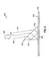
- FIG. 6illustrates a prism interferometer
- FIG. 7is a graph of the loss spectrum of a typical germanium-doped silicate fiber.
- FIG. 8illustrates an embodiment of the present invention which outputs a fourth harmonic beam.
- FIG. 9illustrates an embodiment of the present invention for forming a Bragg grating by using a fourth harmonic beam.
- FIG. 10illustrates an embodiment of the present invention which outputs a fourth harmonic beam.
- the firstis a “holographic” method, wherein two ultraviolet beams are caused to interfere with one another. The resulting interference pattern is projected onto the germanium-doped portion of the fiber.
- the second basic methodis noninterferometric and involves exposure of the fiber to periodic ultraviolet (“IV”) radiation.
- FIG. 1A basic holographic method is shown schematically in FIG. 1 .
- ultraviolet source 105typically some form of laser
- beam splitter 110For low-coherence sources, it is advantageous to equalize the path lengths of beams 112 and 114 . In FIG. 1, these path lengths are equalized by disposing compensating plate 140 in the path of beam 114 .
- Beams 112 and 114reflect from mirrors 115 and 120 , respectively, and are thereby directed to create interference pattern 125 in doped portion 130 of optical fiber 135 .
- This methodis described, for example, in U.S. Pat. No. 4,725,110 (see, for example, col. 1, line 56 through col. 2, line 68 and the referenced figures), the teachings of which are hereby incorporated by reference.
- the second basic methodis noninterferometric and involves exposure of the fiber to periodic ultraviolet UV radiation.
- the periodic UV radiationcan be generated, for example, by having the fiber and a pulsed UV source move relative to one another.
- the periodic UV radiationcan be generated using a spatially periodic grating mask (also known as a “phase mask” or “phase grating”) that is imaged or photo imprinted onto the fiber.
- Phase masksare typically made by etching grooves into a UV-transmitting silica plate using an electron beam, or by holographic exposure.
- FIG. 2A method of using a phase mask as a “proximity mask” is schematically shown in FIG. 2 .
- Ultraviolet beam 205projects an image of mask 210 , producing FBG 215 in doped portion 220 of fiber 230 .
- Mask 210is a “chirped” grating, in which the spacing of the grooves in mask 210 varies from end to end. In another embodiment, mask 210 is not chirped, but instead has grooves with equal widths.
- a projection masking techniquemay be employed by disposing imaging optics between mask 210 and fiber 230 .
- imaging opticsBy using optics which magnify or reduce the spacing of the grooves in mask 210 , an FBG may be formed with a period (or range of periods) which is different from that of mask 210 .
- Phase masksare versatile elements and may be used in combination with various devices for producing FBG's.
- a phase maskmay be used in place of beam-splitter 110 in the holographic device shown in FIG. 1 .
- phase maskmay more advantageously be used in a “phase mask interferometer,” in which a phase mask is used both as a beam-splitter and as a wavelength-defining element.
- FIG. 3depicts a simplified version of phase mask interferometer 300 .
- UV rays 303 and 305which are illustrative of a plurality of rays comprising input beam 301 , illuminate lens 307 .
- Lens 307directs rays 309 and 311 to diffraction points 310 and 312 , respectively, of mask 313 .
- Mask 313is preferably a single-phase mask.
- Rays 314 and 316are exemplary rays diffracted from diffraction point 310
- rays 322 and 324are exemplary rays diffracted from diffraction point 312
- Rays 314 and 322are reflected by mirror 320 to fiber 340
- Rays 316 and 324are reflected by mirror 330 to fiber 340
- Beams 314 and 316intersect at doped portion 350 of fiber 340 , as do rays 322 and 324 , producing portions of FBG 355 .
- the angle between incident ray 322 and the normal to fiber 340is known as “half-writing angle” ⁇ /2.
- the Bragg wavelength ⁇ Braggmay be expressed as a function of the half-writing ⁇ /2 as follows:
- Equation (1)The derivation of Equation (1) is explained in numerous publications and will not be repeated here. (See, e.g., Kayshap, Fiber Bragg Gratings (Academic Press 1999) at pp. 58-63.)
- phase mask interferometer 300may be highly tunable if mirrors 320 and 330 can be moved laterally or if the distance between mask 313 and fiber 340 can be altered: either of these adjustments changes the half-writing angle and therefore changes the Bragg wavelength. Therefore, in one preferred embodiment, phase mask interferometer 300 includes an actuator and a controller for adjusting the separation between mask 313 and fiber 340 , thereby changing the half-writing angle and tuning the Bragg wavelength. In another preferred embodiment, phase mask interferometer 300 includes an actuator for laterally moving at least one of mirrors 320 and 330 , thereby tuning the Bragg wavelength.
- mirrors 320 and 330may be rotated about one or more axes.
- mirrors 320 and 330are rotated such that rays 314 , 316 , 322 and 324 are reflected out of the plane of FIG. 3, and fiber 340 is positioned where the foregoing rays are directed. Accordingly, direct ray 318 is not incident on fiber 340 and zero-order energy is suppressed.
- a slanted gratingis produced in fiber 355 by positioning fiber 340 at an angle ⁇ with respect to direct ray 318 .
- phase mask interferometer 300includes means for rotating fiber 340 around its long axis while being exposed to UV radiation.
- phase mask interferometer 300includes actuators for moving input beam 301 and lens 307 laterally along mask 313 , as indicated by the arrows adjacent to mask 313 in FIG. 3 .
- This scanning techniqueallows FBG 355 to be made relatively long. The quality of FBG's produced using a scanning technique depends on the precision with which mask 313 is manufactured.
- UV light rays 405 and 410are incident upon phase mask 415 .
- Diffracted rays 420 and 425 emitted from phase mask 415are refracted by block 430 and produce FBG 435 in doped layer 440 of fiber 445 .
- Block 430replaces mirrors 320 and 330 of the device shown in FIG. 3 and provides stability to phase mask interferometer 400 .
- Block 430may be made of any convenient material, such as silica.
- FBG'smay be produced using a single “Lloyd” mirror, as shown in Lloyd Bragg writer 500 of FIG. 5 .
- Input rays 505 , 510 and 515are parallel to one another and are examples of the many ray paths of input beam 518 .
- Input ray 505is reflected from mirror 520 and interferes with ray 510 .
- the interference between rays such as 505 and 510is shown schematically by the vertical lines in zone 525 . This interference pattern causes FBG 530 in doped layer 535 of fiber 540 .
- Input beam 518should have a coherence length equal to at least the path difference introduced by the “fold” in the beam.
- the intensity profile and coherence propertiesshould be relatively constant across input beam 518 .
- Fiber 540is preferably oriented perpendicular to mirror 520 .
- a prism interferometeroperates in a similar fashion to a Lloyd mirror, except that a prism replaces the mirror.
- selected paths of input beam 602are shown by representative rays 605 , 610 and 615 .
- Ray 605is refracted by inclined face 620 of prism 622 , then reflected by vertical face 624 of prism 622 to interfere with rays 610 and 615 , which are only refracted.
- the resulting interference patterncreates FBG 625 in doped portion 630 of fiber 635 .
- Prism 622is preferably a right-angled prism such that input beam 602 is bisected.
- Prism 622may be made of any convenient material, but is advantageously made from UV-transmitting silica.
- Inclined face 620is advantageously coated by antireflection material.
- Prism interferometer 600is intrinsically more stable than Lloyd Bragg writer 500 , because the rays of the former device are reflected and diffracted inside prism 622 instead of in air.
- One embodiment of prism interferometer 600includes an actuator for rotating prism 622 , thereby tuning the Bragg wavelength of FBG 625 .
- FIG. 7is a composite graph which indicates the loss spectrum of a typical telecommunications fiber between 200 and 500 nm.
- the measured fiberwas a single-mode fiber with a composition of 3-mol. % germanium.
- the data between 200 and 275 nmwere obtained using a V-groove splicing technique and are plotted with reference to the scale on the left margin of the graph.
- the data between 300 and 500 runwere obtained by using a standard cutback technique and are plotted with reference to the scale on the right margin of the graph.
- the resulting wavelengthwould be 257.5 nm. If the fundamental frequency were quintupled, the resulting wavelength would be 206 run. Referring to FIG. 7, it is apparent that neither of these wavelengths would be suitable for efficient FBG production. If the fundamental frequency of a 1.07 ⁇ m (1070 nm) diode-pumped laser were quadrupled, the resulting wavelength would be 267.5 nm. If the fundamental frequency were quintupled, the resulting wavelength would be 214 nm. These wavelengths are even further from 240 nm than the harmonics of the 1.03 ⁇ m diode-pumped laser and therefore even less desirable for FBG production.
- diode laser 802emits beam 805 at approximately 946 nm, which is frequency doubled in doubler crystal 810 .
- Second harmonic beam 815interacts with quadrupler crystal 820 and is converted to fourth harmonic 825 to provide output in the vicinity of 237 nm.
- Diode laser 802may be any suitable diode laser, including an edge-emitting diode laser (such as an InGaAs diode laser) or a VCSEL that is electrically or optically pumped.
- an edge-emitting diode lasersuch as an InGaAs diode laser
- a VCSELthat is electrically or optically pumped.
- diode laser 802comprises an InGaAs diode operating near 960 nm. Since the intensity of the laser diode is low in this embodiment, it is advantageous to resonate beam 805 in a cavity containing doubler crystal 810 , then resonate the resulting second harmonic radiation in a cavity containing quadrupler crystal 820 .
- Doubler crystal 810 and quadrupler crystal 820may be placed within a cavity which contains diode laser 802 or in one or more external cavities. Doubler crystal 810 and quadrupler crystal 820 are preferably disposed in external cavities so as to increase the conversion efficiency to the second, then the fourth, harmonic.
- Doubler crystal 810may be composed of various materials, including but not limited to lithium triborate (“LBO”), lithium niobate, periodic-poled lithium niobate (“PPLN”), potassium niobate, potassium titanyl phosphate (“KTP”), isomorphs of KTP, such as rubidium titanyl phosphate (“RTP”), cesium titanyl phosphate (“CTP”), potassium titanyl arsenate (“KTA”), rubidium titanyl arsenate (“RTA”), or periodic-poled isomorphs of KTP.
- Quadrupler crystal 820may be composed of beta-barium borate (“BBO”) or cesium lithium borate (“CLBO”). In one preferred embodiment, quadrupler crystal 820 comprises a CLBO crystal used in a non-critically phase-matched orientation. Both doubler crystal 810 and quadrupler crystal 820 are preferably selected to minimize or eliminate beam “walkoff.”
- diode laser 802comprises a VCSEL
- one or more external resonant cavitiesare advantageously used to produce the second and fourth harmonic beams, as described in U.S. Provisional Application No. 60/269,150 on pages 2 and 3 and FIG. 1 . Accordingly, pages 2 and 3 and FIG. 1 of U.S. Provisional Application No. 60/269,150 are hereby incorporated by reference.
- pump 905pumps laser medium 910 , which is disposed within cavity 915 formed by mirrors 920 and 925 .
- Q-switch 930 and tuning element 935are also disposed within resonator 915 .
- Mirror 925is partially transmissive for beam 940 , which has a wavelength of approximately 946 nm.
- Beam 940is directed to crystal 945 , which emits second harmonic beam 950 .
- Crystal 955converts second harmonic beam 950 to fourth harmonic beam 960 at approximately 237 run.
- fourth harmonic beam 960illuminates proximity mask 980 , which produces FBG 982 in doped portion 984 of fiber 985 .
- crystals 945 and 955are disposed within cavity 965 , formed by mirrors 970 and 975 .
- crystals 945 and 955are disposed within separate cavities: crystal 945 is in cavity 966 , formed by mirror 970 and mirror 962 , and crystal 955 is in cavity 964 , formed by 962 and 975 .
- crystals 945 and 955are disposed within cavity 915 .
- Pump 905could be any suitable pump, including a flash lamp or a laser. Although pump 905 is depicted end-pumping laser medium 910 , in some embodiments pump 905 side-pumps laser medium 910 . In some embodiments, pump 905 comprises a diode laser. In one such embodiment, pump 905 comprises an edge-emitting diode laser. In another embodiment, pump 905 comprises a vertical cavity surface emitting diode laser (VCSEL) that is electrically or optically pumped. In some embodiments, pump 905 is a diode bar laser such as an incoherent beam combination (“IBC”) diode laser. In one such embodiment, pump 905 is an IBC diode bar laser.
- IBCincoherent beam combination
- laser medium 910is a Yb- or Nd-doped garnet (such as YAG).
- laser medium 910is an Nd:YAG laser being operated on a transition at 946 nm, or Nd doped into other hosts at similar wavelengths.
- laser medium 910is an Nd:YAG laser and beam 940 has a wavelength of approximately 946 nm, which is quadrupled to produce fourth harmonic beam 960 at approximately 237 nm.
- an Nd:YAG laser crystalis advantageously pumped by an IBC diode laser.
- the wavelength spectrum of the IBC diode laseris centered in the range of 802 nm to 812 nm, the wavelength range in which an Nd:YAG laser crystal is most strongly absorptive. Id. at p. 7 and FIG. 4 .
- the IBC diode laseris preferably used to end-pump laser medium 910 , as disclosed in U.S. Provisional Application No. 60/276,651.
- Q-switch 930may be operated at any convenient frequency, but is preferably operated at between 5,000 and 50,000 Hz. Proper use of a device such as Q-switch 930 is important for all pulsed-output embodiments of the present invention in order to control the peak power of the output beam, thereby reducing damage to the optical fiber during the production of FBG's.
- Q-switch 930typically generates pulse widths in the range of 50-500 nanoseconds (ns), but may generate longer or shorter pulses as needed for the particular application.
- the following examplewill illustrate the effect of repetition rate on the peak output power. If the average output power of a solid-state laser is 1 Watt, a 20,000 Hz. repetition rate and the 100 ns pulse width results in a peak power of about 500W. If the average power is 1 W, the pulse width remains 100 ns and Q-switch 93 G is set to 5,000 Hz., the peak power is about 2,000 W. Accordingly, by varying the pulse width and the repetition rate, output beams having a wide range of peak power may be generated for a given average output power. Such peak power may be well above 2,000 W or well below 500 W, based on the requirements of the particular application.
- the exemplary range of peak powercompares favorably to the peak power of an excimer laser.
- a typical 1-Watt excimer laserhas a repetition rate of around 400 Hz. and a pulse width of 20 ns, yielding a peak power of about 125,000 W.
- Using pulses with such high peak power for making fiber Bragg gratingshas beer shown to substantially weaken the fibers.
- Continuous-wave argon ion fiber Bragg writersare reported to cause much less damage to the optical fibers. However, argon ion fiber Bragg writers have high operating costs and produce weak output powers of one-half watt or less, leading to poor production throughput.
- solid state fiber Bragg writers of the present inventionpeak power can be controlled to cause minimal damage to the optical fibers.
- solid state fiber Bragg writerscan yield sufficiently high power in the output beam to allow greater production throughput than argon ion fiber Bragg writers.
- the combination of low-to-moderate peak power and high repetition ratesmake the solid state fiber Bragg writers of the present invention superior to both excimer and argon ion fiber Bragg writers.
- laser 900can be operated either pulsed or in continuous wave (“cw”) mode.
- cwcontinuous wave
- the frequency doubling and quadrupling stepsare preferably done in separate resonant cavities so as to increase conversion efficiency.
- crystal 945is in cavity 965 , formed by mirror 970 and mirror 962
- crystal 955is in cavity 964 , formed by 962 and 975 .
- Crystals 945 and 955may be formed of numerous materials. Suitable materials for crystal 945 include, but are not limited to, lithium triborate (“LBO”), lithium niobate, periodic-poled lithium niobate (“PPLN”), potassium niobate, potassium titanyl phosphate (“KTP”), isomorphs of KTP, such as rubidium titanyl phosphate (“RTP”), cesium titanyl phosphate (“CTP”), potassium titanyl arsenate (“KTA”), rubidium titanyl arsenate (“RTA”) and periodic-poled isomorphs of KTP.
- Crystal 955may be composed of various materials including, but not limited to, beta-barium borate (“BBO”) and cesium lithium borate (“CLBO”).
- crystals 945 and 955are preferably selected to minimize or eliminate beam walkoff.
- crystal 955comprises a CLBO crystal used in a non-critically phase-matched orientation.
- CLBOis between 2 and 20 times more efficient than prior art “quadrupler” crystals for generating light in the wavelength range from 236 nm to 250 nm. This seems to be primarily due to the ability to avoid walkoff during the conversion from approximately 480 nm to approximately 240 nm.
- VCSEL 1005(not drawn to scale) includes active layer 1010 between n-doped distributed Bragg reflector mirror 1020 and p-doped distributed Bragg reflector mirror 1020 .
- VCSEL 1005produces beam 1025 having a wavelength of approximately 980 nm. Beam 1025 is reflected by mirror 1035 to doubler crystal 1040 , which is disposed within cavity 1042 , formed by mirrors 1045 and 1050 .
- Doubler crystal 1040produces second harmonic beam 1055 , which is directed by mirror 1060 to quadrupler crystal 1065 , which is positioned within cavity 1067 formed by mirrors 1070 and 1075 .
- Quadrupler crystal 1065produces fourth harmonic beam 1080 at approximately 240 nm.
- beam 1025is tuned to other wavelengths in the range from approximately 920 nm to 1 ⁇ m.
- Doubler crystal 1040 and quadrupler crystal 1065may be formed of any of the materials discussed above.
- quadrupler crystal 1065comprises a CLBO crystal used in a non-critically phase-matched orientation which minimizes or eliminates beam “walkoff.” This embodiment is achievable when beam 1025 has a wavelength near 946 n.
Landscapes
- Physics & Mathematics (AREA)
- General Physics & Mathematics (AREA)
- Optics & Photonics (AREA)
- Nonlinear Science (AREA)
- Engineering & Computer Science (AREA)
- Manufacturing & Machinery (AREA)
- Condensed Matter Physics & Semiconductors (AREA)
- Electromagnetism (AREA)
- Lasers (AREA)
Abstract
Description
Claims (56)
Priority Applications (1)
| Application Number | Priority Date | Filing Date | Title |
|---|---|---|---|
| US10/042,943US6832024B2 (en) | 2000-11-20 | 2001-11-19 | Method and apparatus for fiber bragg grating production |
Applications Claiming Priority (5)
| Application Number | Priority Date | Filing Date | Title |
|---|---|---|---|
| US24998900P | 2000-11-20 | 2000-11-20 | |
| US26915001P | 2001-02-15 | 2001-02-15 | |
| US26915201P | 2001-02-15 | 2001-02-15 | |
| US27665101P | 2001-03-16 | 2001-03-16 | |
| US10/042,943US6832024B2 (en) | 2000-11-20 | 2001-11-19 | Method and apparatus for fiber bragg grating production |
Publications (2)
| Publication Number | Publication Date |
|---|---|
| US20030048523A1 US20030048523A1 (en) | 2003-03-13 |
| US6832024B2true US6832024B2 (en) | 2004-12-14 |
Family
ID=27534817
Family Applications (1)
| Application Number | Title | Priority Date | Filing Date |
|---|---|---|---|
| US10/042,943Expired - LifetimeUS6832024B2 (en) | 2000-11-20 | 2001-11-19 | Method and apparatus for fiber bragg grating production |
Country Status (1)
| Country | Link |
|---|---|
| US (1) | US6832024B2 (en) |
Cited By (50)
| Publication number | Priority date | Publication date | Assignee | Title |
|---|---|---|---|---|
| US20050169326A1 (en)* | 2004-01-30 | 2005-08-04 | Jacob James J. | Laser architectures for coherent short-wavelength light generation |
| US20110157684A1 (en)* | 2009-12-28 | 2011-06-30 | Industrial Technology Research Institute | UV Light Generator |
| US9286673B2 (en) | 2012-10-05 | 2016-03-15 | Volcano Corporation | Systems for correcting distortions in a medical image and methods of use thereof |
| US9292918B2 (en) | 2012-10-05 | 2016-03-22 | Volcano Corporation | Methods and systems for transforming luminal images |
| US9301687B2 (en) | 2013-03-13 | 2016-04-05 | Volcano Corporation | System and method for OCT depth calibration |
| US9307926B2 (en) | 2012-10-05 | 2016-04-12 | Volcano Corporation | Automatic stent detection |
| US9324141B2 (en) | 2012-10-05 | 2016-04-26 | Volcano Corporation | Removal of A-scan streaking artifact |
| US9360630B2 (en) | 2011-08-31 | 2016-06-07 | Volcano Corporation | Optical-electrical rotary joint and methods of use |
| US9367965B2 (en) | 2012-10-05 | 2016-06-14 | Volcano Corporation | Systems and methods for generating images of tissue |
| US9383263B2 (en) | 2012-12-21 | 2016-07-05 | Volcano Corporation | Systems and methods for narrowing a wavelength emission of light |
| US9478940B2 (en) | 2012-10-05 | 2016-10-25 | Volcano Corporation | Systems and methods for amplifying light |
| US9486143B2 (en) | 2012-12-21 | 2016-11-08 | Volcano Corporation | Intravascular forward imaging device |
| US9596993B2 (en) | 2007-07-12 | 2017-03-21 | Volcano Corporation | Automatic calibration systems and methods of use |
| US9612105B2 (en) | 2012-12-21 | 2017-04-04 | Volcano Corporation | Polarization sensitive optical coherence tomography system |
| US9622706B2 (en) | 2007-07-12 | 2017-04-18 | Volcano Corporation | Catheter for in vivo imaging |
| US9709379B2 (en) | 2012-12-20 | 2017-07-18 | Volcano Corporation | Optical coherence tomography system that is reconfigurable between different imaging modes |
| US9730613B2 (en) | 2012-12-20 | 2017-08-15 | Volcano Corporation | Locating intravascular images |
| US9770172B2 (en) | 2013-03-07 | 2017-09-26 | Volcano Corporation | Multimodal segmentation in intravascular images |
| US9858668B2 (en) | 2012-10-05 | 2018-01-02 | Volcano Corporation | Guidewire artifact removal in images |
| US9867530B2 (en) | 2006-08-14 | 2018-01-16 | Volcano Corporation | Telescopic side port catheter device with imaging system and method for accessing side branch occlusions |
| US10058284B2 (en) | 2012-12-21 | 2018-08-28 | Volcano Corporation | Simultaneous imaging, monitoring, and therapy |
| US10070827B2 (en) | 2012-10-05 | 2018-09-11 | Volcano Corporation | Automatic image playback |
| USRE47101E1 (en) | 2003-03-20 | 2018-10-30 | Agjunction Llc | Control for dispensing material from vehicle |
| US10166003B2 (en) | 2012-12-21 | 2019-01-01 | Volcano Corporation | Ultrasound imaging with variable line density |
| US10191220B2 (en) | 2012-12-21 | 2019-01-29 | Volcano Corporation | Power-efficient optical circuit |
| US10219887B2 (en) | 2013-03-14 | 2019-03-05 | Volcano Corporation | Filters with echogenic characteristics |
| US10219780B2 (en) | 2007-07-12 | 2019-03-05 | Volcano Corporation | OCT-IVUS catheter for concurrent luminal imaging |
| US10226597B2 (en) | 2013-03-07 | 2019-03-12 | Volcano Corporation | Guidewire with centering mechanism |
| US10238367B2 (en) | 2012-12-13 | 2019-03-26 | Volcano Corporation | Devices, systems, and methods for targeted cannulation |
| US10292677B2 (en) | 2013-03-14 | 2019-05-21 | Volcano Corporation | Endoluminal filter having enhanced echogenic properties |
| US10332228B2 (en) | 2012-12-21 | 2019-06-25 | Volcano Corporation | System and method for graphical processing of medical data |
| US10413317B2 (en) | 2012-12-21 | 2019-09-17 | Volcano Corporation | System and method for catheter steering and operation |
| US10420530B2 (en) | 2012-12-21 | 2019-09-24 | Volcano Corporation | System and method for multipath processing of image signals |
| US10426590B2 (en) | 2013-03-14 | 2019-10-01 | Volcano Corporation | Filters with echogenic characteristics |
| US10568586B2 (en) | 2012-10-05 | 2020-02-25 | Volcano Corporation | Systems for indicating parameters in an imaging data set and methods of use |
| US10595820B2 (en) | 2012-12-20 | 2020-03-24 | Philips Image Guided Therapy Corporation | Smooth transition catheters |
| US10638939B2 (en) | 2013-03-12 | 2020-05-05 | Philips Image Guided Therapy Corporation | Systems and methods for diagnosing coronary microvascular disease |
| US10724082B2 (en) | 2012-10-22 | 2020-07-28 | Bio-Rad Laboratories, Inc. | Methods for analyzing DNA |
| US10758207B2 (en) | 2013-03-13 | 2020-09-01 | Philips Image Guided Therapy Corporation | Systems and methods for producing an image from a rotational intravascular ultrasound device |
| US10939826B2 (en) | 2012-12-20 | 2021-03-09 | Philips Image Guided Therapy Corporation | Aspirating and removing biological material |
| US10942022B2 (en) | 2012-12-20 | 2021-03-09 | Philips Image Guided Therapy Corporation | Manual calibration of imaging system |
| US10993694B2 (en) | 2012-12-21 | 2021-05-04 | Philips Image Guided Therapy Corporation | Rotational ultrasound imaging catheter with extended catheter body telescope |
| US11026591B2 (en) | 2013-03-13 | 2021-06-08 | Philips Image Guided Therapy Corporation | Intravascular pressure sensor calibration |
| US11040140B2 (en) | 2010-12-31 | 2021-06-22 | Philips Image Guided Therapy Corporation | Deep vein thrombosis therapeutic methods |
| US11141063B2 (en) | 2010-12-23 | 2021-10-12 | Philips Image Guided Therapy Corporation | Integrated system architectures and methods of use |
| US11154313B2 (en) | 2013-03-12 | 2021-10-26 | The Volcano Corporation | Vibrating guidewire torquer and methods of use |
| US11272845B2 (en) | 2012-10-05 | 2022-03-15 | Philips Image Guided Therapy Corporation | System and method for instant and automatic border detection |
| US11406498B2 (en) | 2012-12-20 | 2022-08-09 | Philips Image Guided Therapy Corporation | Implant delivery system and implants |
| US12201477B2 (en) | 2012-10-05 | 2025-01-21 | Philips Image Guided Therapy Corporation | Methods and systems for establishing parameters for three-dimensional imaging |
| US12343198B2 (en) | 2013-03-14 | 2025-07-01 | Philips Image Guided Therapy Corporation | Delivery catheter having imaging capabilities |
Families Citing this family (5)
| Publication number | Priority date | Publication date | Assignee | Title |
|---|---|---|---|---|
| US6701044B2 (en)* | 2001-08-10 | 2004-03-02 | Lightwave Electronics | Solid state laser generating UV radiation for writing fiber bragg gratings |
| US7751030B2 (en)* | 2005-02-01 | 2010-07-06 | Asml Holding N.V. | Interferometric lithographic projection apparatus |
| RU2014137183A (en)* | 2012-02-13 | 2016-04-10 | РеалД, Инк. | Laser system architecture (options) |
| US10914902B2 (en) | 2014-02-26 | 2021-02-09 | TeraDiode, Inc. | Methods for altering properties of a radiation beam |
| US9435964B2 (en) | 2014-02-26 | 2016-09-06 | TeraDiode, Inc. | Systems and methods for laser systems with variable beam parameter product |
Citations (5)
| Publication number | Priority date | Publication date | Assignee | Title |
|---|---|---|---|---|
| US5621497A (en)* | 1994-04-06 | 1997-04-15 | Hitachi, Ltd. | Pattern forming method and projection exposure tool therefor |
| US20020081068A1 (en)* | 2000-12-26 | 2002-06-27 | Sadayuki Matsumoto | Method of manufacturing grating |
| US6483965B1 (en)* | 2000-08-11 | 2002-11-19 | Nortel Networks Limited | Method of writing a bragg diffraction grating |
| US20020176647A1 (en)* | 2001-05-11 | 2002-11-28 | Spirin Vasilii V. | Differential fiber optical sensor with interference energy analyzer |
| US20030031411A1 (en)* | 2001-08-10 | 2003-02-13 | Arbore Mark A. | Solid state laser generating UV radiation for writing fiber bragg gratings |
- 2001
- 2001-11-19USUS10/042,943patent/US6832024B2/ennot_activeExpired - Lifetime
Patent Citations (6)
| Publication number | Priority date | Publication date | Assignee | Title |
|---|---|---|---|---|
| US5621497A (en)* | 1994-04-06 | 1997-04-15 | Hitachi, Ltd. | Pattern forming method and projection exposure tool therefor |
| US6483965B1 (en)* | 2000-08-11 | 2002-11-19 | Nortel Networks Limited | Method of writing a bragg diffraction grating |
| US20020081068A1 (en)* | 2000-12-26 | 2002-06-27 | Sadayuki Matsumoto | Method of manufacturing grating |
| US20020176647A1 (en)* | 2001-05-11 | 2002-11-28 | Spirin Vasilii V. | Differential fiber optical sensor with interference energy analyzer |
| US20030031411A1 (en)* | 2001-08-10 | 2003-02-13 | Arbore Mark A. | Solid state laser generating UV radiation for writing fiber bragg gratings |
| US6701044B2 (en)* | 2001-08-10 | 2004-03-02 | Lightwave Electronics | Solid state laser generating UV radiation for writing fiber bragg gratings |
Cited By (60)
| Publication number | Priority date | Publication date | Assignee | Title |
|---|---|---|---|---|
| USRE47101E1 (en) | 2003-03-20 | 2018-10-30 | Agjunction Llc | Control for dispensing material from vehicle |
| US20050169326A1 (en)* | 2004-01-30 | 2005-08-04 | Jacob James J. | Laser architectures for coherent short-wavelength light generation |
| US9867530B2 (en) | 2006-08-14 | 2018-01-16 | Volcano Corporation | Telescopic side port catheter device with imaging system and method for accessing side branch occlusions |
| US9596993B2 (en) | 2007-07-12 | 2017-03-21 | Volcano Corporation | Automatic calibration systems and methods of use |
| US10219780B2 (en) | 2007-07-12 | 2019-03-05 | Volcano Corporation | OCT-IVUS catheter for concurrent luminal imaging |
| US11350906B2 (en) | 2007-07-12 | 2022-06-07 | Philips Image Guided Therapy Corporation | OCT-IVUS catheter for concurrent luminal imaging |
| US9622706B2 (en) | 2007-07-12 | 2017-04-18 | Volcano Corporation | Catheter for in vivo imaging |
| US20110157684A1 (en)* | 2009-12-28 | 2011-06-30 | Industrial Technology Research Institute | UV Light Generator |
| US8270069B2 (en)* | 2009-12-28 | 2012-09-18 | Industrial Technology Research Institute | UV light generator |
| US11141063B2 (en) | 2010-12-23 | 2021-10-12 | Philips Image Guided Therapy Corporation | Integrated system architectures and methods of use |
| US11040140B2 (en) | 2010-12-31 | 2021-06-22 | Philips Image Guided Therapy Corporation | Deep vein thrombosis therapeutic methods |
| US9360630B2 (en) | 2011-08-31 | 2016-06-07 | Volcano Corporation | Optical-electrical rotary joint and methods of use |
| US9324141B2 (en) | 2012-10-05 | 2016-04-26 | Volcano Corporation | Removal of A-scan streaking artifact |
| US9858668B2 (en) | 2012-10-05 | 2018-01-02 | Volcano Corporation | Guidewire artifact removal in images |
| US11510632B2 (en) | 2012-10-05 | 2022-11-29 | Philips Image Guided Therapy Corporation | Systems for indicating parameters in an imaging data set and methods of use |
| US9478940B2 (en) | 2012-10-05 | 2016-10-25 | Volcano Corporation | Systems and methods for amplifying light |
| US11890117B2 (en) | 2012-10-05 | 2024-02-06 | Philips Image Guided Therapy Corporation | Systems for indicating parameters in an imaging data set and methods of use |
| US9367965B2 (en) | 2012-10-05 | 2016-06-14 | Volcano Corporation | Systems and methods for generating images of tissue |
| US11272845B2 (en) | 2012-10-05 | 2022-03-15 | Philips Image Guided Therapy Corporation | System and method for instant and automatic border detection |
| US11864870B2 (en) | 2012-10-05 | 2024-01-09 | Philips Image Guided Therapy Corporation | System and method for instant and automatic border detection |
| US9286673B2 (en) | 2012-10-05 | 2016-03-15 | Volcano Corporation | Systems for correcting distortions in a medical image and methods of use thereof |
| US9307926B2 (en) | 2012-10-05 | 2016-04-12 | Volcano Corporation | Automatic stent detection |
| US10070827B2 (en) | 2012-10-05 | 2018-09-11 | Volcano Corporation | Automatic image playback |
| US12201477B2 (en) | 2012-10-05 | 2025-01-21 | Philips Image Guided Therapy Corporation | Methods and systems for establishing parameters for three-dimensional imaging |
| US9292918B2 (en) | 2012-10-05 | 2016-03-22 | Volcano Corporation | Methods and systems for transforming luminal images |
| US10568586B2 (en) | 2012-10-05 | 2020-02-25 | Volcano Corporation | Systems for indicating parameters in an imaging data set and methods of use |
| US10724082B2 (en) | 2012-10-22 | 2020-07-28 | Bio-Rad Laboratories, Inc. | Methods for analyzing DNA |
| US10238367B2 (en) | 2012-12-13 | 2019-03-26 | Volcano Corporation | Devices, systems, and methods for targeted cannulation |
| US9709379B2 (en) | 2012-12-20 | 2017-07-18 | Volcano Corporation | Optical coherence tomography system that is reconfigurable between different imaging modes |
| US9730613B2 (en) | 2012-12-20 | 2017-08-15 | Volcano Corporation | Locating intravascular images |
| US11892289B2 (en) | 2012-12-20 | 2024-02-06 | Philips Image Guided Therapy Corporation | Manual calibration of imaging system |
| US11406498B2 (en) | 2012-12-20 | 2022-08-09 | Philips Image Guided Therapy Corporation | Implant delivery system and implants |
| US11141131B2 (en) | 2012-12-20 | 2021-10-12 | Philips Image Guided Therapy Corporation | Smooth transition catheters |
| US10942022B2 (en) | 2012-12-20 | 2021-03-09 | Philips Image Guided Therapy Corporation | Manual calibration of imaging system |
| US10939826B2 (en) | 2012-12-20 | 2021-03-09 | Philips Image Guided Therapy Corporation | Aspirating and removing biological material |
| US10595820B2 (en) | 2012-12-20 | 2020-03-24 | Philips Image Guided Therapy Corporation | Smooth transition catheters |
| US11253225B2 (en) | 2012-12-21 | 2022-02-22 | Philips Image Guided Therapy Corporation | System and method for multipath processing of image signals |
| US11786213B2 (en) | 2012-12-21 | 2023-10-17 | Philips Image Guided Therapy Corporation | System and method for multipath processing of image signals |
| US10191220B2 (en) | 2012-12-21 | 2019-01-29 | Volcano Corporation | Power-efficient optical circuit |
| US9383263B2 (en) | 2012-12-21 | 2016-07-05 | Volcano Corporation | Systems and methods for narrowing a wavelength emission of light |
| US9486143B2 (en) | 2012-12-21 | 2016-11-08 | Volcano Corporation | Intravascular forward imaging device |
| US10420530B2 (en) | 2012-12-21 | 2019-09-24 | Volcano Corporation | System and method for multipath processing of image signals |
| US10058284B2 (en) | 2012-12-21 | 2018-08-28 | Volcano Corporation | Simultaneous imaging, monitoring, and therapy |
| US9612105B2 (en) | 2012-12-21 | 2017-04-04 | Volcano Corporation | Polarization sensitive optical coherence tomography system |
| US10166003B2 (en) | 2012-12-21 | 2019-01-01 | Volcano Corporation | Ultrasound imaging with variable line density |
| US10413317B2 (en) | 2012-12-21 | 2019-09-17 | Volcano Corporation | System and method for catheter steering and operation |
| US10332228B2 (en) | 2012-12-21 | 2019-06-25 | Volcano Corporation | System and method for graphical processing of medical data |
| US10993694B2 (en) | 2012-12-21 | 2021-05-04 | Philips Image Guided Therapy Corporation | Rotational ultrasound imaging catheter with extended catheter body telescope |
| US10226597B2 (en) | 2013-03-07 | 2019-03-12 | Volcano Corporation | Guidewire with centering mechanism |
| US9770172B2 (en) | 2013-03-07 | 2017-09-26 | Volcano Corporation | Multimodal segmentation in intravascular images |
| US11154313B2 (en) | 2013-03-12 | 2021-10-26 | The Volcano Corporation | Vibrating guidewire torquer and methods of use |
| US10638939B2 (en) | 2013-03-12 | 2020-05-05 | Philips Image Guided Therapy Corporation | Systems and methods for diagnosing coronary microvascular disease |
| US12350018B2 (en) | 2013-03-12 | 2025-07-08 | Philips Image Guided Therapy Corporation | Systems and methods for diagnosing coronary microvascular disease |
| US11026591B2 (en) | 2013-03-13 | 2021-06-08 | Philips Image Guided Therapy Corporation | Intravascular pressure sensor calibration |
| US10758207B2 (en) | 2013-03-13 | 2020-09-01 | Philips Image Guided Therapy Corporation | Systems and methods for producing an image from a rotational intravascular ultrasound device |
| US9301687B2 (en) | 2013-03-13 | 2016-04-05 | Volcano Corporation | System and method for OCT depth calibration |
| US10219887B2 (en) | 2013-03-14 | 2019-03-05 | Volcano Corporation | Filters with echogenic characteristics |
| US10426590B2 (en) | 2013-03-14 | 2019-10-01 | Volcano Corporation | Filters with echogenic characteristics |
| US10292677B2 (en) | 2013-03-14 | 2019-05-21 | Volcano Corporation | Endoluminal filter having enhanced echogenic properties |
| US12343198B2 (en) | 2013-03-14 | 2025-07-01 | Philips Image Guided Therapy Corporation | Delivery catheter having imaging capabilities |
Also Published As
| Publication number | Publication date |
|---|---|
| US20030048523A1 (en) | 2003-03-13 |
Similar Documents
| Publication | Publication Date | Title |
|---|---|---|
| US6832024B2 (en) | Method and apparatus for fiber bragg grating production | |
| US7184616B2 (en) | Method and apparatus for fiber Bragg grating production | |
| US5321718A (en) | Frequency converted laser diode and lens system therefor | |
| US5195104A (en) | Internally stimulated optical parametric oscillator/laser | |
| US7535938B2 (en) | Low-noise monolithic microchip lasers capable of producing wavelengths ranging from IR to UV based on efficient and cost-effective frequency conversion | |
| KR102100728B1 (en) | Highly Efficient, Single-Pass, Harmonic Generator with Round Output Beam | |
| Johnson et al. | Narrow-bandwidth low-divergence optical parametric oscillator for nonlinear frequency-conversion applications | |
| US5473409A (en) | Semiconductor light exposure device | |
| US20050238071A1 (en) | One-dimensional illumination apparatus and imaging apparatus | |
| US6836592B2 (en) | Method and apparatus for fiber Bragg grating production | |
| CN101276126A (en) | Double Brewster's Angle Nonlinear Optical Crystal and Its Cutting Method | |
| EP3079009A1 (en) | Multi-wavelength laser device | |
| US5561676A (en) | Compound-cavity, high-power, modelocked semiconductor laser | |
| JPH04330791A (en) | Optical modulator | |
| US5754572A (en) | Mirrorless, distributed-feedback, ultraviolet, tunable, narrow-linewidth, solid state laser | |
| Ziegler et al. | Tunable 50-fs pulse generation in the 250-310-nm ultraviolet range | |
| Piskarskas et al. | The parametric generation of bandwidth-limited picosecond light pulses | |
| WO2007053083A1 (en) | Laser source for the infrared wavelength range | |
| JPH10270781A (en) | Method and device for generating laser light | |
| JPH07142805A (en) | Semiconductor aligner and exposure method | |
| KR950002068B1 (en) | Second harmonic generation method and apparatus | |
| JP2759893B2 (en) | Harmonic generator | |
| JP3312447B2 (en) | Semiconductor exposure equipment | |
| US20090219956A1 (en) | Device for Generating Narrowband Optical Radiation | |
| JP2007073552A (en) | Laser light generator and image formation apparatus |
Legal Events
| Date | Code | Title | Description |
|---|---|---|---|
| FEPP | Fee payment procedure | Free format text:PAYOR NUMBER ASSIGNED (ORIGINAL EVENT CODE: ASPN); ENTITY STATUS OF PATENT OWNER: LARGE ENTITY | |
| STCF | Information on status: patent grant | Free format text:PATENTED CASE | |
| FEPP | Fee payment procedure | Free format text:PAT HOLDER NO LONGER CLAIMS SMALL ENTITY STATUS, ENTITY STATUS SET TO UNDISCOUNTED (ORIGINAL EVENT CODE: STOL); ENTITY STATUS OF PATENT OWNER: LARGE ENTITY | |
| FPAY | Fee payment | Year of fee payment:4 | |
| AS | Assignment | Owner name:LOCKHEED MARTIN CORPORATION, MARYLAND Free format text:ASSIGNMENT OF ASSIGNORS INTEREST;ASSIGNOR:ACULIGHT CORPORATION;REEL/FRAME:021763/0985 Effective date:20080829 Owner name:LOCKHEED MARTIN CORPORATION,MARYLAND Free format text:ASSIGNMENT OF ASSIGNORS INTEREST;ASSIGNOR:ACULIGHT CORPORATION;REEL/FRAME:021763/0985 Effective date:20080829 | |
| AS | Assignment | Owner name:LOCKHEED MARTIN CORPORATION, MARYLAND Free format text:ASSIGNMENT OF ASSIGNORS INTEREST;ASSIGNORS:BOWERS, MARK S.;LOWENTHAL, DENNIS D.;FARMER, JASON N.;AND OTHERS;SIGNING DATES FROM 20080919 TO 20080922;REEL/FRAME:024879/0130 Owner name:ACULIGHT CORPORATION, WASHINGTON Free format text:ASSIGNMENT OF ASSIGNORS INTEREST;ASSIGNOR:GERSTENBERGER, DAVID C.;REEL/FRAME:024879/0120 Effective date:20080707 | |
| FPAY | Fee payment | Year of fee payment:8 | |
| FPAY | Fee payment | Year of fee payment:12 | |
| AS | Assignment | Owner name:LOCKHEED MARTIN CORPORATION, MARYLAND Free format text:CHAIN OF TITLE;ASSIGNOR:LOCKHEED MARTIN ACULIGHT CORPORATION;REEL/FRAME:045094/0484 Effective date:20180110 | |
| AS | Assignment | Owner name:LOCKHEED MARTIN SONAR SYSTEMS CORPORATION, NEW YOR Free format text:CHANGE OF NAME;ASSIGNOR:LORAL SONAR SYSTEMS CORPORATION;REEL/FRAME:045110/0834 Effective date:19960429 |