US6830731B1 - Immunoassay fluorometer - Google Patents
Immunoassay fluorometerDownload PDFInfo
- Publication number
- US6830731B1 US6830731B1US09/003,090US309098AUS6830731B1US 6830731 B1US6830731 B1US 6830731B1US 309098 AUS309098 AUS 309098AUS 6830731 B1US6830731 B1US 6830731B1
- Authority
- US
- United States
- Prior art keywords
- fluorometer
- test
- sample
- information
- assay device
- Prior art date
- Legal status (The legal status is an assumption and is not a legal conclusion. Google has not performed a legal analysis and makes no representation as to the accuracy of the status listed.)
- Expired - Lifetime, expires
Links
Images


Classifications
- G—PHYSICS
- G01—MEASURING; TESTING
- G01N—INVESTIGATING OR ANALYSING MATERIALS BY DETERMINING THEIR CHEMICAL OR PHYSICAL PROPERTIES
- G01N21/00—Investigating or analysing materials by the use of optical means, i.e. using sub-millimetre waves, infrared, visible or ultraviolet light
- G01N21/62—Systems in which the material investigated is excited whereby it emits light or causes a change in wavelength of the incident light
- G01N21/63—Systems in which the material investigated is excited whereby it emits light or causes a change in wavelength of the incident light optically excited
- G01N21/64—Fluorescence; Phosphorescence
- G01N21/645—Specially adapted constructive features of fluorimeters
- Y—GENERAL TAGGING OF NEW TECHNOLOGICAL DEVELOPMENTS; GENERAL TAGGING OF CROSS-SECTIONAL TECHNOLOGIES SPANNING OVER SEVERAL SECTIONS OF THE IPC; TECHNICAL SUBJECTS COVERED BY FORMER USPC CROSS-REFERENCE ART COLLECTIONS [XRACs] AND DIGESTS
- Y10—TECHNICAL SUBJECTS COVERED BY FORMER USPC
- Y10T—TECHNICAL SUBJECTS COVERED BY FORMER US CLASSIFICATION
- Y10T436/00—Chemistry: analytical and immunological testing
- Y10T436/11—Automated chemical analysis
- Y10T436/112499—Automated chemical analysis with sample on test slide
- Y—GENERAL TAGGING OF NEW TECHNOLOGICAL DEVELOPMENTS; GENERAL TAGGING OF CROSS-SECTIONAL TECHNOLOGIES SPANNING OVER SEVERAL SECTIONS OF THE IPC; TECHNICAL SUBJECTS COVERED BY FORMER USPC CROSS-REFERENCE ART COLLECTIONS [XRACs] AND DIGESTS
- Y10—TECHNICAL SUBJECTS COVERED BY FORMER USPC
- Y10T—TECHNICAL SUBJECTS COVERED BY FORMER US CLASSIFICATION
- Y10T436/00—Chemistry: analytical and immunological testing
- Y10T436/11—Automated chemical analysis
- Y10T436/115831—Condition or time responsive
Definitions
- the present inventionrelates generally to fluorometers, and more particularly to a system and method for performing automated fluorescent measurements.
- Typical fluorometersare bench-top devices which are not easily transported from location to location. Additionally, conventional fluorometers are not easily capable of being programmed by the user or otherwise configured by the user to perform a plurality of different types of tests. Instead, the conventional fluorometer is factory-programmed to perform a predefined test protocol.
- a laboratory technicianobtains a sample.
- the samplecan be a biological fluid, such as blood, serum, plasma, urine, a fecal extract and the like or it can be an environmental sample, such as water, a ground extract, a chemical and the like or it can be an extract of a food product.
- the bloodis first separated into plasma or serum, which becomes the sample, and cellular fractions using a centrifuge.
- the sampleis then generally deposited into a small test tube that is inserted into the fluorometer. Because the conventional fluorometer can accept several samples, the technician enters an identification of the sample and the location of the test tube into the fluorometer.
- test tubes containing samplesOnce one or more test tubes containing samples are positioned in the fluorometer, the test begins. Contemporary fluorometers use robotics to pipet the sample and the reagents and to position one or more optical sensors by the sample to obtain the necessary readings. The readings are recorded along with the associated test-tube location designations. The location designation is used to identify the sample.
- the present inventionprovides a system and method for performing automated fluorometry.
- a fluorometeris provided which includes functionality to provide enhanced operational characteristics for the measurement of analytes in a sample.
- the system and methodhas particular importance as a laboratory or non-laboratory tool for rapidly and conveniently measuring analytes by skilled laboratorian or by individuals who are unskilled as laboratorians.
- the fluorometercan include an optical block, a removable storage medium, an internal processor, a communications interface, and internal data storage.
- the system and methodgenerally comprises the fluorometer and a testing or assay device.
- the assay deviceis used in conjunction with the fluorometer to achieve a result regarding the concentration or presence of an analyte in a sample.
- analytesinclude chemicals, proteins, peptides, bacteria, viruses, nucleic acids, cellular organelles, cells, receptors and the like.
- the assay devicecan include reagents that are necessary for performing an immunological or chemical reaction, such reaction giving rise to a change in fluorescence of the sample that has been treated with the reagents.
- the reagentscan include chemicals, antibodies, peptides, analytes, analyte analogues and these reagents may or may not be coupled to fluorescent labels or to solid phases.
- the removable storage mediumis implemented utilizing a ROM chip or other memory device, which can be interfaced to the fluorometer to provide operating instructions as well as calibration curves and control and calibration data.
- the memory deviceis mounted on a carrier which provides easy insertion and removal such that a plurality of memory devices containing specific sets of data can be easily interchanged. In this manner, the fluorometer can be easily programmed and re-programmed to perform a variety of tests and calibrations.
- the removable storage mediumcan be implemented using a removable medium such as a disk and disk drive.
- the diskcan contain test data sets for one or more types of tests to be performed.
- the test data setscan include test instructions and calibration curves for the test, as well as other program information and calibration and control information for the instrument.
- a communications interfacecan be included to facilitate communications between the fluorometer and one or more other devices.
- the communications interfacecan include a wired and wireless interface to provide direct or networked communications.
- the communications interfacecan be used to download test data sets, including, for example, test identifications, test instructions and calibration curves, as well as other program information and calibration and control information.
- the communications interfacecan also be used to allow the fluorometer to share processing responsibilities with other devices such as a computer or other processor.
- Such an interfacecan be implemented, for example, utilizing an RS-232, infrared or modem interface for direct connection, or a network interface for network communications to one or more processors.
- the communications interfaceis used to allow a physician or other health care professional at a health care facility (e.g., a doctor's office, clinic, testing center, hospital, or other health care site or facility) to transmit test instructions to the fluorometer with regard to which tests are to be performed for a particular patient.
- a health care facilitye.g., a doctor's office, clinic, testing center, hospital, or other health care site or facility
- the interfacecan also be used to forward test results to a health care facility to apprise the health care professional of the results. Results of tests and a catalog of tests performed can be sent to various locations for patient-diagnosis, record-keeping, billing, and other purposes.
- a patientcan perform testing at home, and test results and instructions can be exchanged with a health care facility via the communications interface.
- patients who require frequent monitoringcan get the necessary tests without traveling to a health care facility each time a test is needed, for example, as may be required by patients taking daily regimens of therapeutic drugs.
- a technician in the fieldcan measure water or ground contamination and transmit the results to a home office via a cellular telephone or other communications medium to inform officials of the progress of a decontamination procedure.
- Internal data storagecan be used to store program instructions (including test instructions), calibration curves, control and calibration data as well as other data used in the operation of the fluorometer. Internal data storage can also provide register space for operand storage. Internal data storage can be implemented using, for example, RAM or DRAM technology, or other memory technology. Disk or other storage space can be used to supplement the internal data storage, depending on storage cost and access latency tradeoffs. Cache techniques can also be used to optimize performance.
- Test informationcan include information such as, an identification of the patient and other patient information, a sample identification, an identification of a test or tests performed on the sample, a date and time at which the tests were conducted, test conditions, test results, specific reagent information, such as lot numbers and expiration dates and other pertinent information.
- the test informationcan be stored in a record that can be indexed using, for example, the patient identification or other indexing designation.
- Input interfacescan include data entry devices such as a keyboard, keypad, touch-screen display, mouse, voice recognition input, or other data entry device.
- Output interfacescan include a display screen or monitor, printer, speaker or other output device.
- the assay mechanismincludes a motorized mechanism for transporting the assay device in the fluorometer.
- a motorized mechanisminclude, for example, those as described in U.S. Pat. No. 5,458,852 and U.S. patent application Ser. No. 08/458,276, now U.S. Pat. No. 5,922,615 titled “Devices For Ligand Receptor Methods,” which are incorporated herein by reference.
- the movement of the assay device in the fluorometerfunctions to position the diagnostic lane of the device with an optical block so that one or more fluorescent areas or zones of the assay device can be measured.
- the degree or presence of fluorescence in the diagnostic laneis related to the concentration or presence of analyte in the sample.
- the optical blockcan include a light source, detector and optics used to excite the sample as well as to sense the fluorescence of the excited sample.
- the sampleis disposed on the assay device.
- the assay mechanismcan provide the capability to transport the assay device along the optical block such that fluorescence of one or more of a plurality of zones on the diagnostic lane of the device can be measured.
- one advantage of the invention according to this embodimentis that enhanced testing algorithms can be utilized, if desired, in measuring the fluorescence of the sample.
- the communications interfacecan be used to allow the fluorometer to be interfaced to networks such as, for example, a hospital or other health care facility network, or other information networks whereby the fluorometer can retrieve data which may be needed to conduct tests and download other data including the test results.
- the communications interfacecan be used to interface with the fluorometer to a stand alone computer such as, for example, a personal computer or an office or a home office computer.
- the fluorometercan utilize the processing and peripheral capabilities of the stand alone computer or network resources to supplement its own processing and interface capabilities.
- the fluorometercan interface with an existing instrument that is interfaced to a network, such as, for example, an instrument in a hospital emergency department or critical care unit that dispenses medications for use by the hospital personnel.
- a networksuch as, for example, an instrument in a hospital emergency department or critical care unit that dispenses medications for use by the hospital personnel.
- Interfacing the fluorometer to an existing instrumenthas advantages in that the interface of the fluorometer to the instrument can be one specific code, whereas the instrument interface code can be varied depending on the location of the instrument, for example, in different hospitals with different software interface codes.
- the fluorometercan be operated as a portable hand-carried piece of test equipment that is used to test samples of blood.
- the portable, hand-carried unitcan then be interfaced to a computer or computer network to upload test results or to simply communicate other data associated with the test and to use the processing power of the computer or computer network to perform some or all of the actual test processing.
- test data sets or other pertinent informationcan be downloaded from the outside entity to provide the fluorometer with guidance as to tests to be conducted on a particular sample. This guidance can be in the form of complete test instructions or simply an identification of a test to be performed for which the instructions are stored internally to the fluorometer.
- the data communicated to a networkcan be utilized in real time to diagnose and treat acute care patients.
- sample informationcan include, for example, an identification of the sample and sample type, an identification of the patient from which the sample was drawn, an indication of the test or tests to be performed for the sample, as well as other data, as desired.
- Reagent informationcan include the type of reagents in a device, lot specific information, such as calibration information and expiration dating.
- test results and other data relating to the testcan be automatically stored along with the patient identification and other associated information such that data for a patient can easily be accessed.
- Another embodiment of the inventionis to utilize an encoder, such as for example a magnetic strip encoder, in the instrument to encode information on an assay device.
- patient informationincluding patient number, tests to be performed and the like can be entered through the keypad of the instrument or via a centralized computer that downloads the information to the fluorometer.
- the encoderrecords the information onto the assay device, such that when the user inserts the assay device into the fluorometer, a reader reads the information on the assay device and combines the assay results with the encoded information.
- the combined informationcan be stored in the fluorometer and it can be communicated to a network for real time or later analysis.
- Yet another feature of the inventionis that internal data storage can be provided so that patient information and test results can be tracked in the form of a history log.
- a history logFor example, in a portable hand-held environment, a user or technician may test several samples of blood in a given time interval. The test results, along with the identification of the patient, can be stored in the local database such that a history log of tests and test results are maintained. This history log can then be downloaded via the communications interface or onto a removable media.
- the identification of the patientcan be based on an automatic number identification (referred to as ANI).
- ANIautomatic number identification
- the ANI signalprovided by the telephone network is used by the health-care facility to identify the patient from which the communication originated.
- the ANIcan be used in place of the an identification of the patient based on the encoded label, or in addition thereto to provide a cross check against potential identification errors.
- FIG. 1is a diagram illustrating a representative functional architecture of a fluorometer according to one embodiment of the invention.
- FIG. 2is a diagram generally illustrating an operational scenario of the fluorometer according to one embodiment of the invention.
- FIG. 3is a diagram illustrating a representative functional architecture of the assay mechanism according to one embodiment of the invention.
- FIG. 4is a diagram illustrating an example implementation of the fluorometer with a health care facility according to one embodiment of the invention.
- FIG. 5is a diagram illustrating an operational scenario of the fluorometer in conjunction with a health care facility according to one embodiment of the invention.
- FIG. 6is a diagram illustrating an example implementation of the fluorometer in conjunction with a separate computer according to one embodiment of the invention.
- FIG. 7is a diagram illustrating a process for testing a plurality of sample areas according to one embodiment of the invention.
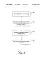
- FIG. 8is a diagram illustrating a process for removing a background signal from the test results according to one embodiment of the invention.
- FIG. 9is a diagram illustrating an example of spot locations in terms of signal strength according to one embodiment of the invention.
- FIG. 10is a diagram illustrating a process for integrating fluorescent intensity over the test range according to one embodiment of the invention.
- FIG. 11is a diagram illustrating an optical package used to excite the sample and receive the signal according to one embodiment of the invention.
- FIG. 12which comprises FIGS. 12A and 12B, is a diagram illustrating an example implementation of a chip carrier according to one embodiment of the invention.
- FIG. 13is a diagram illustrating in more detail one embodiment of a leading edge of the chip carrier illustrated in FIG. 12 .
- FIG. 14is a diagram illustrating an example implementation of a ROM chip mounted on a printed circuit board according to one embodiment of the invention.
- FIG. 15is a diagram illustrating a cross-sectional view of a slot and tab according to one embodiment of the invention.
- FIG. 16is a block diagram illustrating an example computer system in which elements and functionality of the invention are implemented according to one embodiment of the invention.
- FIG. 1is a diagram illustrating a functional block diagram of an enhanced fluorometer according to one embodiment of the invention.
- FIG. 1illustrates examples of the functionalities that can be included with the automated fluorometer in terms of one example physical architecture, a central bus structure. After reading this description, it will become apparent to one of ordinary skill in the art how to implement any or all of the described functionality using one or more alternative architectures.
- the enhanced fluorometerincludes a processor 104 , a power supply 108 , a user interface 112 , a memory 116 , a communications interface 120 , an assay device 124 , a storage device 128 , and removable storage media.
- the removable mediainclude a ROM chip 136 and ROM chip socket 132 , and a disk drive 138 . Any or all of these functionalities can be included with an enhanced fluorometer depending on the particular application.
- Processor 104controls the operation of the fluorometer and also provides control for the various functionalities provided with the fluorometer.
- Processor 104can be a central processor that controls the functionality via a bus structure or other communications interface.
- processor 104can be implemented by distributing the processing functions among one or more of the various components utilized to implement the functionalities of the fluorometer.
- Power supply 108is used to provide necessary power to the fluorometer and its components.
- Power supply 108can be implemented using batteries, solar cells, transformers used to convert an AC power source, or other techniques to provide the appropriate power levels to the components.
- power supply 108is implemented using rechargeable batteries such as, for example, NiCad or Nickel Metal Hydride batteries which can be recharged using a charger connected to AC power from a conventional wall outlet. The use of rechargeable batteries provides a practical power source for portable applications.
- User interface 112provides one or more devices through which a user can interface with a fluorometer.
- user interface 112includes a keypad 162 , a display 164 , and a printer 166 . Additional or alternative interfaces can be provided such as, for example, a keyboard, mouse, track ball, touch-screen display, or other user interface devices.
- keypad 162is a small alphanumeric keypad that provides the user with input keys to assist in the direction of the functionality of the fluorometer. Keypad 162 can also include special function keys to perform single-touch operations. The function keys can be preprogrammed to perform specified functions, or user programs, depending on the application.
- Display 164can be implemented using a number of display devices such as, for example, a small monochromatic LCD display. A small LCD display is preferable for portable applications because of its legibility and low power requirements. For non-portable applications display 164 can be implemented using, for example, a CRT or a color LCD display.
- printer 166can be implemented using a variety of different printing techniques.
- printer 166can be implemented using a small thermal printer such as that found on small calculators or adding machines.
- a small thermal printersuch as that found on small calculators or adding machines.
- larger printerscan be used.
- Memory 116is used to provide storage for program data or other data used by processor 104 during operation.
- Memory 116can be implemented using various RAM or ROM memory devices.
- Memory 116can be used for example, to store operating instructions and to provide memory registers for operating and storage.
- Memorycan also be used in conjunction with a storage device 128 such as a disk storage device.
- Storage device 128can also be used to store program instructions, control and calibration curves, operational data, history logs, and other data which may be desired to be stored within the fluorometer.
- storage device 128is used to store large amounts of data, and the generally more costly but faster memory 116 is used to store only data which must be accessed more frequently or more rapidly.
- a cachecan be provided to minimize latencies associated with retrieving frequently used data from storage device 128 .
- ROM chip socket 132can be included to provide a means by which a ROM chip 136 containing program instructions, calibration curves, control data, or other information can be interfaced to the fluorometer.
- Communications interface 120can be provided to allow the fluorometer to communicate with various external devices. Depending on the desired applications and the environments in which the fluorometer is operating, various alternative communications interfaces can be provided. Communications interface 120 can be implemented to include wired and wireless interfaces such as, for example, an RS-232 interface, an infrared interface, an RF interface, a network interface, or other communications interface appropriate for the application. Through the use of communications interface 120 , the fluorometer can share information with other entities such as test results, test statistics, and other information, as well as receive information and instructions from outside entities.
- Assay mechanism 124is used to perform the fluorometric readings on the sample in order to test the presence or concentration of one or more analytes.
- assay mechanism 124is a slide mechanism that is used to accept a small tray-like device, for example, an assay device.
- Assay mechanism 124includes the optical components necessary to perform the fluorometric readings as well as a slide on which the assay device slides to position the assay zones in the appropriate location so that fluorescence can be measured in a reproducible manner.
- the mechanismis motorized such that the assay device can be automatically loaded and ejected from the fluorometer as well as positioned with respect to the optics during testing.
- the path which includes optics used to excite the sample and sense the fluorescenceis referred to as the diagnostic lane of the device.
- all of the data and instructions necessary to operate the fluorometercan be provided on ROM chip 136 .
- all of the memory requirements of the fluorometerare provided by the ROM chip 136 .
- memory requirementsare shared among or redistributed to any or all of these storage devices.
- a removable storage mediumsuch as, for example, ROM chip 136 or a disk in disk drive 138 is utilized to provide operating instructions to the fluorometer.
- this memory deviceis a ROM chip 136 .
- the functionality of the fluorometeris described in terms of this preferred embodiment. After reading this description, it will become apparent to one of ordinary skill in the art how to implement removable storage medium using other storage devices.
- ROM chip 136can also be used to provide other pertinent data to the fluorometer to be used in controlling and calibrating the fluorometer as well as calibration curves for performing the various tests.
- ROM chip 136includes test software used to conduct one or more tests.
- test softwarecan include program instructions used to direct the fluorometer to perform one or more fluorometric tests on a sample.
- one or more testscan be provided using a single ROM chip 136 .
- each different type of test or assayis provided on a single ROM chip.
- ROM chip 136is replaced with the appropriate ROM chip 136 containing the desired test software in socket 132 .
- the test software and associated calibration and control information, and software for a plurality of testscan be provided on a single ROM chip 136 .
- the need to exchange ROM chips 136can be minimized.
- the ROM chip 136 softwareis downloaded to the fluorometer so that a number of tests can be accessed by the fluorometer without changing ROM chip 136 .
- ROM chip 136An important functionality which can also be provided by ROM chip 136 is that different tests can be provided on different ROM chips such that “reprogramming” of the fluorometer to perform a variety of different tests can be accomplished simply by replacing ROM chip 136 .
- ROM chip 136can also include calibration curves utilized to perform the desired test. Because different tests typically utilize different calibration curves, in one embodiment, the calibration curves are provided on ROM chip 136 along with the test software. ROM chip 136 can also include control and calibration data to calibrate the fluorometer using controlled solutions. Because control and calibration information may change based on the test being performed, this information in one embodiment is provided with each ROM chip 136 such that the fluorometer can be properly configured and calibrated to perform the desired tests.
- ROM chips 136 containing instrument specific, test specific, and calibration specific informationcan be the same or different. In a preferred embodiment, specific chips are used to provide specific functionality. Examples of this functionality are now described according to one embodiment of the invention.
- Instrument specific operational software for one or more testsresides on a single ROM chip 136 termed a program ROM key.
- a chip termed a reagent code chipprovides test specific information, including calibration information for one or more tests and lots of tests.
- Control solution information, including concentrations and ranges of analytes and expiration dating of the solutionsresides on another ROM chip 136 termed QC Sample Code Chip.
- Calibrator solution informationincluding concentrations and ranges of analytes and expiration dating of the calibrator solution resides on another ROM chip 136 termed Calibrator Code Chip.
- Supervisor Code Chipinformation relating to expected values measured by a QC simulator resides on yet another ROM key 136 termed Instrument Validation Code Chip.
- FIG. 2is an operational flow diagram generally illustrating an operation of the fluorometer according to one embodiment of the invention.
- softwareis loaded to perform the desired test.
- a ROM chip or memory device 136is inserted into socket 132 , the ROM chip 136 containing the software for the test to be performed.
- the test softwarecan be loaded using communications interface 120 , disk drive 138 , ROM chip 136 , storage device 128 or other interface.
- the loadingcan include the transfer of any or all instructions and data to internal memory 1116 or storage 128 , or can simply encompass making these instructions and data available to processor 104 via access of the utilized device or interface.
- the fluorometeris calibrated.
- the calibrationcan be performed using calibration software with controlled test solutions.
- an assay devicetermed a QC simulator, comprising a fluorescent zone or zones is inserted into the fluorometer.
- the fluorescent value of the QC simulatoris a known value that can be loaded into the fluorometer via a ROM key or a bar code on the assay device.
- a fluorescent chiptermed an internal calibrator, is within the fluorometer that is read by the fluorometer prior to each measurement of an assay device. The intensity of the fluorescence of the internal calibrator is a known quantity.
- an assay device with sample to be testedis loaded into the fluorometer. In one embodiment, this is accomplished by inserting an assay device containing the sample into assay mechanism 124 .
- a bar code symbol or other encoded tagis used to provide an identification of the sample to be tested.
- the encoded tagis read by the fluorometer such that the test results can be correlated with or later associated with the particular sample being tested. Examples of an encoded tag can include a bar code symbol, an encoded magnetic strip, a character designation capable of being read by an optical character reader, or a tag made using some other encoding technique.
- sampleis tested.
- Samples to be testedcan include, for example, biological fluid such as blood, serum, plasma, urine; a fecal extract and the like; an environmental sample such as water, a ground extract, a chemical and the like; or an extract of a food product.
- the testingis performed in accordance with the instructions provided by the software loaded in step 204 .
- various testing techniquescan be used to optimize the test results. Examples of such techniques relating to immunological reactions are described in Principles and Practice of Immunoassay, C. P. Price and D. J. Newman, Macmillian Reference Ltd., 1997, and U.S. Pat. Nos.
- a preferred embodimentis used in conjunction with a motorized assay mechanism 124 to allow a plurality of sample zones or regions on an assay device to be tested.
- the results of the testsare provided.
- the test resultscan be printed on printer 166 , displayed on display 164 , stored in a local memory or storage device within the fluorometer, written to a medium such as a disk in disk drive 138 , or communicated to an external entity via communications interface 120 .
- the test resultsare displayed, printed, stored or transmitted along with the identification of the sample obtained using the encoded tag such that the test results can always be associated with the proper sample.
- the use of an encoded tag in this mannerhelps to assure that the test results are always associated with the proper sample.
- FIG. 3is a diagram illustrating an example implementation of an assay mechanism or assay device drive according to one embodiment of the invention.
- the assay device driveincludes drive electronics 304 , a position encoder 308 , and an encoded tag reader 312 such as, for example, a bar code reader.
- drive electronics 304includes a motor to position the assay device and a motor controller to control the motor.
- a friction drive, gear drive, or other mechanismcan be used to translate the rotation of the motor into motion of the assay device.
- Drive electronics 304are thus used to load and eject the assay device as well as to position the assay device with respect to the optics of the fluorometer, for example, along the diagnostic lane.
- the assay deviceis moved in relation to stationary optics.
- the opticscan be moved instead of, or in addition to, the assay device.
- Position encoder 308is used to determine the position of the assay device within assay device drive 300 .
- Position encoder 308can obtain position information from the assay device itself such as, for example, by sensing an encoded label on the assay device.
- position encoder 308can determine the position of the assay device based on the rotation of the drive shaft through the motor using well-known encoder techniques.
- Encoded device reader 312is used to read the encoded tag provided on the assay device.
- encoded tag reader 312is a bar code reader that reads a bar code label on the assay device.
- Alternative embodimentscan include, for example, a magnetic stripe reader, an inductive reader, or an optical character recognizer.
- An encoded tag reader 312senses the encoded tag information from the label on the assay device and provides this information to processor 104 .
- the encoded informationcan include information such as, for example, a patient I.D., an identification of the tests to be performed on the sample, an identification of the sample type, or other appropriate or pertinent information. This information can be used to log the test results as well as to control the type of testing performed or test parameters used.
- drive electronics 304 and position encoder 308are used to control the positioning of the assay device, as well as to reposition the assay device during testing such that a plurality of regions of the assay device can be tested.
- This capability to position the assay device such that various portions of the sample can be testedallows enhanced testing algorithms to be utilized to produce improved test results.
- An example of enhanced testing routines that can be used where different regions of an assay device are testedis fully described in copending patent applications of common assignee, now U.S. Pat. No. 5,763,189, having application Ser. No. 08/311,098, and titled “Fluorescence Energy Transfer and Intramolecular Energy Transfer in Particles Using Novel Compounds” and application Ser. No. 08/409,298 also titled “Fluorescence Energy Transfer and Intramolecular Energy Transfer in Particles Using Novel Compounds,” which are incorporated herein by reference.
- FIG. 4is a block diagram illustrating an example implementation of a fluorometer 100 used in communication with an information system 408 to perform fluorometric tests.
- a communications interface 120can be provided to allow the fluorometer 100 to communicate with outside entities such as, for example, a hospital network, a physician's office, a testing clinic, other laboratory computers, or other relevant entities.
- outside entitiessuch as, for example, a hospital network, a physician's office, a testing clinic, other laboratory computers, or other relevant entities.
- the outside entityis a health care information system 408 such as, for example, a hospital data system that can be accessed by a physician or other health care professional to order tests for and treat a patient.
- information system 408is implemented to include a data entry terminal 462 and a data storage device 464 .
- information system 408can be implemented using alternative architectures.
- a blood sampleis drawn from the patient.
- the vials containing the bloodare labeled with an identification of the patient and sent to the lab that will perform the fluorometric tests.
- the technician at the labreceives the blood sample, prepares the assay device and places the encoded I.D. label 412 onto the assay device.
- I.D. label 412identifies the assay device as belonging to the patient from which the sample was withdrawn.
- I.D. label 412can be generated by the lab technician or transferred from the received vials.
- FIG. 5is an operational flow diagram illustrating an example process by which the sample can be tested in an automated fashion with fluorometer 100 in communication with information system 408 utilizing communications interface 120 .
- an assay deviceis prepared with a sample and labeled with an encoded tag.
- the prepared samplethat is, an assay device with the sample added, is loaded into fluorometer 100 .
- the assay deviceis a cassette or tray-like container.
- the assay deviceincludes an encoded I.D. tag 412 which can provide, for example, an identification of the patient from which the sample is drawn, an indication of the assay or assays to be performed and can include additional information as may be deemed relevant for the particular application. Any additional information required can be downloaded or entered by the health care professional via user interface 112 .
- the encoded I.D. tag 412provides an identification of the type of test that is being performed, for example, a test that assesses the condition of a patient with respect to a myocardial infarction.
- the lab technicianenters the patient information, for example, the patient number, via keypad 162 .
- an encoded labelis not used and all necessary information is obtained through downloading, manual entry or a combination thereof.
- fluorometer 100reads the encoded tag on the assay device.
- information from encoded tag 412and/or any additional information downloaded and/or entered, or a translation thereof, is sent to information system 408 to access information or to download information about the patient or about tests ordered for that patient.
- the health care professional at the hospital ordering tests for the patientcan enter in the patient's name or other identification as well as a list or identification of tests ordered for that patient into system 408 .
- the patient's name or identification and the tests to be performed for that patientare stored in database 464 so that there is a record of the tests ordered for that patient.
- the information sent to information system 408is used to access the database, to thereby retrieve information indicating which tests are ordered for the patient.
- test instructionswhich can include, for example, instructions for performing a desired test, or an identification of the test or tests ordered for the patient, are downloaded to fluorometer 100 using communications interface 120 .
- fluorometer 100performs the test, after the technician loads the assay device, by either carrying out the downloaded instructions, or by accessing the instructions locally (e.g., by local storage, by input from keypad 162 or from ROM chip) based on an identification of the test received from information system 408 . Where a different ROM chip 136 or disk needs to be installed to perform the required test, the user is informed via user interface 112 .
- the testingis performed automatically without user intervention.
- timing algorithmssuch as those described below are implemented to control the timing of the assay process.
- the testis carried out and completed automatically without intervention.
- Alternative embodimentsmay provide the capability of the system to prompt the user for certain inputs as deemed appropriate.
- resultsare provided to information system 408 .
- the resultscan be stored in database 464 and are identified as being associated with the patient. As such, results of the tests can be accessed by health care professionals using terminal 462 and can be printed to provide a hard copy of the results.
- the additional test informationcan include, for example, an identification of the patient and other patient information, a sample identification, an identification of a test or tests performed on the sample, a date and time at which the tests were conducted, test conditions, test results and other pertinent information.
- This test informationcan be used to update database 464 such that information system 408 has a complete record of tests, results and associated data for a patient.
- the test informationcan be stored in the fluorometer in local storage 128 , memory 116 or on removable storage medium (i.e., ROM chip 136 , removable disk, etc.).
- record flags or other techniquescan be used when the database 464 is accessed to retrieve test instructions. For example, when fluorometer 100 accesses information system 408 to receive instructions for a particular test, that test is flagged as being performed such that subsequent accesses by this or another fluorometer 100 will not retrieve the same test instructions. Once a test is completed and the results provided to information system 408 , another flag can be set indicating the status of the test as being completed.
- I.D. 412can also include a sample identification or a sample type identification.
- a sample identificationFor example, where a prepared sample is plasma, an indication of such is included on I.D. 412 , or alternatively entered by the user using the keypad or other input device on fluorometer 100 .
- fluorometer 100 queries information system 408 to access test instructionstests which are ordered for plasma are checked, and if present, retrieved from database 464 . As illustrated by this example scenario, the chance for operator error in identification of the sample and performing the appropriate tests on that sample, are minimized at the fluorometer.
- label 412can be used to further automate the testing process, even in a stand-alone environment.
- the label 412 codewhen the technician prepares the blood sample, the label 412 code includes a description or indication of the test to be performed on that sample.
- the fluorometerreads the test description or indication, the appropriate test is performed.
- the testcan be automatically accessed from local storage or the user may be prompted to load the test-related information via ROM chip 136 , disk or other memory or storage device.
- Information from the tag 412 as well as tests performed and their resultscan be used to create a record locally on fixed or removable media as well as remotely via communications interface 120 . Information from the record can be used for patient diagnosis, accounting, billing, statistical and other purposes.
- communications interfacecan take on a variety of different physical embodiments such that communication between fluorometer 100 and information system 408 can be implemented using a wireless communication link, a hardware communication link, networks communication, or other communication facilities.
- the patientobtains a sample and places it in the assay device or cassette.
- the samplecan be a blood sample, for example, from a finger prick, a urine sample or other appropriate sample.
- Fluorometer 100can be pre-loaded with test instructions appropriate to the particular patient. Alternatively, fluorometer 100 can utilize communication interface 120 to access test instructions from the clinic, physician's office, hospital or other health-care facility. The patient loads the sample into fluorometer 100 and the appropriate test or tests are conducted.
- Test resultsare forwarded to the health care facility using communications interface 120 so that the patient's records can be updated and the appropriate health care professional can be apprised of the results.
- Fluorometer 100can include an alarm feature that automatically informs or reminds the patient when a test is required.
- This featurecan be implemented, for example, using a built-in programmable clock.
- the clockcan be programmed manually or by installing scheduling instructions. For example, a scheduling program detailing the type or types of tests to be performed and the time for such tests can be installed before fluorometer 100 is delivered to the patient. The installation can be performed, for example, using removable storage media.
- Schedule programmingcan also be downloaded via communications interface 120 both initially, and as treatment progresses. For example, the tending physician may wish to update the testing schedule by adding new tests, changing the testing interval, or discontinuing certain tests. The physician can update information system 408 to reflect this change and the changes can be downloaded via communications interface 120 . In this manner, the testing can be tailored and updated to suit a patient's current needs.
- the scheduling programindicates the type of test to be performed at a scheduled test occurrence.
- Information regarding the test typecan be, but does not need to be provided to the patient. This information, however, along with test results, is preferably provided via communications interface 120 to update the patient's data base or to inform the physician of the test results.
- the scheduling programcan also indicate the sample type required for a particular test.
- the patient's identificationcan be provided to the health-care facility using automatic number identification, or ANI, based on the telephone number from which the test instrument is calling. Where ANI is not available, or where the patient is calling from a location where his or her ANI is not recognized, the system may prompt the patient to enter an identification.
- ANIautomatic number identification
- communications interface 120can be utilized to inform the patient that a personal visit to the health-care professional is required. For example, consider a scenario in which the tending physician is obtaining and reviewing results of regularly conducted tests. The physician may detect a change in condition that warrants a personal appointment. The physician can input this information into the health care information system and the patient is appraised of the necessary appointment.
- the health care information systemmaintains a calendar of available appointment slots for the tending physician.
- the appointmentscan be maintained on the physician's personal computer or on a data server or other accessible data base within the health care information system to facilitate sharing of calendar information among health care professionals.
- a listing of available appointmentsis sent to the patient via communications interface 120 .
- the patientusing user interface 112 reviews the available appointment slots and selects one that fits his or her schedule.
- Fluorometer 100provides this information to health care information system to reserve that slot for the patient.
- a reminder for the appointmentcan be programmed into the internal clock of fluorometer 100 to remind the patient a desired time interval before the appointment.
- the health care information systemcan store this information and send an appropriate reminder to the patient via communications interface 120 .
- communications interface 120in the in-home embodiments allows real-time or near-real-time interaction between the patient and the tending health-care professional although the patient and health care professional are not at the same location. Tests can be conducted and the results reported and analyzed as they are performed. Test schedules can be updated and otherwise modified as the health-care professional deems fit based on results of recent tests.
- the fluorometercan be utilized in conjunction with a separate processor such as, for example, a workstation or personal computer.
- a variety of fluorometer functionalitiescan be delegated to or shared with the separate processor.
- fluorometer 100is interfaced to a personal computer 604 as illustrated in FIG. 6 .
- the interfaceis implemented using an RS-232 communications interface, although other communications interfaces can be selected based on speed, cost and reliability tradeoffs.
- a processorsuch as a personal computer 604 can be utilized to enhance the performance of fluorometer 100
- fluorometer 100performs a plurality of tests on blood samples. After performing the appropriate measurements and readings, the fluorometer provides these results to personal computer 604 .
- fluorometer 100can be considered as providing raw data to personal computer 604 although a certain amount of processing can be performed by fluorometer 100 .
- Personal computer 604accepts the raw data and performs analysis and processing of the data to help to arrive at definitive test results or to interpret therapy for the patient based on the test results. Test results and related data can be described alphanumerically and graphically on the display screen of personal computer 604 . Through user interfaces on personal computer 604 an operator can adjust the functionality of the test as well as test parameters to obtain optimum results.
- FIG. 7is an operational flow diagram illustrating this process according to one embodiment of the invention.
- the assay deviceis stepped along the diagnostic lane such that at each step a different region of the assay device is excited and fluorescent measurements are sensed from that region.
- the assay deviceis stepped in only along one direction (e.g., back and forth or side-to side) and therefore the regions or zones are divided along one direction of the assay device.
- the assay devicecan be stepped, for example, both back and forth, and side to side, such that additional regions on the assay device can be defined.
- the assay deviceis stepped along the diagnostic lane in discrete steps, and fluorescence measured at each step.
- the assay deviceis driven continuously at a given speed along the diagnostic lane, and measurements are taken throughout the process. In either embodiment, the measurements themselves can be at discrete intervals or continuous.
- the results of each regionare recorded.
- the recorded resultsrepresent optical amplitudes sensed from the excited region.
- the data from a particular sampleare recorded and processing is performed upon recorded data such that processing does not have to be performed in real time, and the entire data sample can be utilized in processing.
- step 710data processing begins with checking the quality of the trace.
- the details of this step according to one embodimentare fully described in copending patent applications of common assignee, having application Ser. No. 08/311,098, and titled “Fluorescence Energy Transfer and Intramolecular Energy Transfer in Particles Using Novel Compounds” and application Ser. No. 08/409,298 also titled “Fluorescence Energy Transfer and Intramolecular Energy Transfer in Particles Using Novel Compounds.”
- a residual fluorescent signalis a background signal that can be highly variable from sample to sample. Therefore, in a step 712 it is desired to remove this signal before calculating the amount of fluorescence immobilized on each area of the diagnostic lane for each sample tested.
- the fluorescence intensities measured for each area or region testedare integrated to determine the total amount of fluorescent label immobilized as a result, for example, of an immunological binding reaction.
- a step 716the processed signal without the background is integrated to determine the total fluorescence of the sample.
- the resultis computed, for example by comparison to a threshold, to determine whether the test is positive or the concentration of each analyte being tested.
- the sensed amount of fluorescent labelis a function of the acquisition method. More specifically, the sensed amount of fluorescent label for a given region is the product of the fluorescent strength emitted by that region and the width of the region. Therefore, if the displacement of the assay device varies from the expected displacement the results obtained will be inconsistent and will not be reproducible. For example, if the displacement is shorter than expected, the amount of fluorescent label in the region will be reported as higher for a given sample.
- position encoder 308can be utilized to obtain a measurement of the actual or relative displacement during the test process.
- the positionis encoded by monitoring the rotation of the motor, i.e. using a rotary position encoder. After reading this description, it will become apparent to one of ordinary skill in the art who to implement this functionality utilizing alternative embodiments of rotary encoders. From this, errors in the expected displacement arising from changes in motor speed are factored out.
- the average error between the measured motor position and the assay device positionis recorded as a function of the position of the assay device. This information is used to map the measured motor position into actual assay device position.
- the positionis encoded by monitoring the position of the assay device with respect to the optics, i.e. using a linear position encoder.
- FIG. 8is an operational flow diagram illustrating a manner in which the background signal can be removed according to one embodiment of the invention.
- the spot locations or zones of fluorescence as a result of the assay processare determined by where a signal is received.
- spot locations or assay zonesare defined by the fluorometer software such that the fluorometer is programmed to measure fluorescence in a particular location or locations along the diagnostic lane of the assay device. These spot locations or zones are the points along the length of the diagnostic lane of the assay device at which an amplitude above a determined threshold is received.
- FIG. 9is a diagram illustrating an example of spot locations along the length of the diagnostic lane.
- the ordinateis the amplitude of the fluorescent signal received
- the abscissais the length along the diagnostic lane. Because the assay device is moving along the diagnostic lane, this also represents the position of the assay device with respect to the optics. Thus, travel along the abscissa represents a position in the diagnostic lane along the assay device.
- spot locations or (assay) zones 920there are areas where it is apparent that a signal is received as illustrated by spot 920 , separated by areas in which there is merely background noise 914 . Areas of apparent signal readings are referred to as spot locations or (assay) zones 920 .
- FIG. 10is a diagram illustrating a process by which the fluorescence intensity is integrated over each spot 920 according to one embodiment of the invention. In a step 1002 , the sum of the adjusted fluorescent intensity is calculated.
- this intensityis multiplied by the step distance between each point.
- the step distancerelates to the amount by which the assay device is moved along the diagnostic lane between each data reading.
- variations in the step distanceare factored out of the readings in step 1004 by correcting the step distance according to previously measured calibration data.
- this resultis normalized by the appropriate meter gain.
- the meter gain (G)is a scale factor that represents the relative intensity of the excitation source and the relative sensitivity of the detector.
- the detected signalis the product of the source intensity, the amount of fluorescence and the sensitivity of the detector.
- the resultis normalized by the width of the spot and therefore relates to the average amount of fluorescent label as a result of the assay process. In a preferred embodiment, the result is not normalized by the width of the spot and therefore relates to the total amount of fluorescent label as a result of the assay process.
- step 1006also normalizes the result to the measured signal of the internal standard.
- the intensity of each regionis then multiplied by the length of each region, e.g. the known distance between measurements.
- the length of each region, ⁇ X jcan be a function of position along the diagnostic lane and is not necessarily a constant.
- UFLis multiplied by the meter gain, which scales the result to be independent of the meter.
- the UFLis also multiplied by the expected internal standard value (EISV) and is divided by the measured internal standard value (MISV), yielding an instrument independent result of the total fluorescent label (TF).
- a preferred embodiment of the inventionutilizes dyes that excite and emit in the infrared or near-infrared range, particularly between about 600 nm to 1300 nm.
- the excitation wavelength of the dyeis not a wavelength that, for example, the blood or serum absorbs. As such, energy from the excitation source is not lost.
- the emission wavelengthdoes not correspond to the absorption of the sample such that fluorescent light is not lost.
- the blood and serumdo not fluoresce at these wavelengths, there is reduced background noise sensed by the detector.
- Another preferred embodimentmakes use of dyes that possess Stokes shifts greater than about 90 nm.
- Stokes shifts of greater than 90 nmallow simplification of the design of the optical block, in that special band pass filters are not necessary to block excitation light energy.
- the overlap of excitation and emission lightis minimized as the Stokes shift increases, thus increasing the recovery of fluorescent light from assay device.
- band pass filtersto prevent measuring the excitation light when it is desirable to measure the emitted light.
- the use of band pass filtershas the disadvantages of cost and of decreasing the yield of measured fluorescent light.
- a preferred embodimentutilizes dyes and dye systems of phthalocyanines and hybrid phthalocyanine derivatives that incorporate fluorescence energy transfer in particles, particularly in latex particles having bound antibodies, proteins, ligands and ligand analogues.
- FIG. 11is a block diagram illustrating an example implementation of an optical package that operates effectively with dyes exhibiting these desired properties according to one embodiment of the invention.
- the optical package illustrated in FIG. 11includes an energy source 1102 and an energy detector 1104 (i.e., an optical transmitter and receiver). Additionally, cut-off or band-pass filters 1108 , 1110 can be provided to filter background signal from the energy source 1102 or other sources.
- Energy source 1102is preferably an optical energy source 1102 that emits light in the infrared or near-infrared range portion of the spectrum, but can also emit light in the ultraviolet or visible wavelengths.
- optical energy source 1102emits energy at a wavelength of approximately 670 nm. This wavelength of energy is poorly absorbed by blood or serum and does not cause blood or serum to fluoresce, at least not appreciably.
- Preferred energy sourcesare flash lamps, light emitting diodes and laser diodes. Particularly preferred energy sources are laser diodes.
- the fluorescent energy emitted from the sampleis at a wavelength different from the excited energy.
- the wavelength of the energy emitted as a result of the fluorescence of the dyeis at approximately 760 nm. This wavelength is sufficiently different from that of the excitation wavelength (670 nm), such that energy (excitation) source 1102 will not significantly contribute to the background signal measured by the energy detector 1104 .
- a cutoff filteris used to minimize light greater than about 690 nm from the source.
- one or more filterscan be included.
- a high-pass filter 1108is used to cutoff frequencies of the energy source at frequencies below (wavelengths above) the preferred excitation wavelength which would potentially be a source of background for energy detector 1104 .
- a low-pass filter 1110can be included to cutoff frequencies of the energy source at frequencies above (wavelengths below) the preferred detection frequency.
- Preferred energy detectorsare photomultiplier tubes and silicon photodiodes. Particularly preferred energy detectors are silicon photodiodes.
- energy source 1102 and energy detector 1104are positioned such that the excitation energy emitted from energy source 1102 impinges on the sample at approximately a 45 degree angle.
- Alternative configurationscan be implemented using different angles.
- a plurality of energy sources 1102 and/or detectors 1104can be implemented to optimize the energy readings.
- sourcesgenerally do not provide uniform illumination, and furthermore, a 45 degree angle of incidence will result in a variation in illumination across the sample.
- source 1102contains a special optic that provides for homogenous illumination of the sample.
- this special opticis a micro-lens array.
- the special opticis a diffractive optic, which provides homogenous illumination, including correction for the 45 degree angle of incidence.
- a flattenercan be used in one embodiment to achieve a more uniformly distributed beam pattern.
- flattenerscan include diffusers and diffractive optics.
- a removable storage mediumcan be included to facilitate or enhance the operation of a fluorometer.
- a removable storage mediumis implemented using a socket 132 and a ROM chip 136 .
- ROM chip 136is mounted in a chip carrier that includes contacts to interface with socket 132 .
- the chip carriercan be inserted into and withdrawn from socket 132 to facilitate the change or swapping out of ROM chips 136 .
- An example of ROM chip carrieris now described.
- FIG. 12which comprises FIGS. 12A and 12B, is a diagram illustrating an example implementation of a chip carrier 1200 according to one embodiment of the invention.
- FIG. 12Ais a perspective view of what is referred to as the top surface of chip carrier 1200 .
- chip carrier 1200includes a body portion 1203 and a rear tab 1209 .
- Body portion 1203includes a structure for mounting a ROM chip 136 , as well as for guiding ROM chip 136 into socket 132 .
- Rear tab 1209provides a tab-like structure that facilitates the handling of carrier 1200 and the insertion and removal of carrier 1200 into and out of socket 132 .
- carrier 1200includes a top face 1204 that has an open area 1205 .
- Open area 1205provides an opening through which contacts in socket 132 can access electrical contacts 1408 (illustrated in FIG. 14 ).
- Lateral members 1206define the sides of carrier 1200 and form boundaries of open area 1205 .
- a central member 1206can be included to provide additional structural rigidity, as well as to assist in the guidance of carrier 1200 in socket 132 .
- Leading edge 1208 of carrier 1200is preferably beveled, as are lateral members 1206 . Because these members are beveled, they include a plurality of edges and faces that facilitate alignment during insertion as well as facilitate a tight fit of carrier 1200 within socket 132 .
- FIG. 12Bis a diagram illustrating a bottom view of carrier 1200 according to one preferred embodiment of the invention.
- lateral members 1206 , cross member 1207 and leading edge base 1212provide a frame around a chip cavity 1236 .
- chip cavity 1236in which ROM chip 136 is disposed.
- ROM chip 136is mounted on a relatively flat structure such as a printed circuit board.
- FIG. 14An example implementation of this embodiment is illustrated in FIG. 14 .
- ROM chip 136is mounted on a printed circuit board 1404 .
- a printed circuit board 1404includes a plurality of contacts 1408 that are used to make electrical contact with corresponding contacts in socket 132 .
- Leads 1406are used to connect the leads of ROM chip 136 with contacts 1408 .
- contacts in socket 132are implemented using wiper contacts similar, for example, to those found in phone jacks or circuit board card-edge connectors.
- the wiper contactscan be spring loaded using, for example springs, or the sprung force of the bent contact metal itself.
- the contacts in socket 132 as well as contacts 1408 and leads 1406are implemented using a conductive material, such as, for example, copper, gold, silver or other conductive material.
- the width and thickness of contacts in socket 132 , leads 1406 and contacts 1408 as disposed on printed circuit board 1404can be varied to provide the proper amount of conductivity depending on the implementation. Additionally, the area and thickness provided for a ground plane or ground lead 146 is chosen to provide adequate current handling capacity for grounding.
- Printed circuit board 1404in one embodiment includes tabs 1412 .
- Tabs 1412align with recesses 1214 to facilitate placement of ROM chip 136 and circuit board 1404 within chip cavity 1236 .
- a flexible tab 1234holds printed circuit board 1404 in place.
- a crenelated or other structure 1242can also be provided to help hold circuit board 1404 in place.
- Structure 1242can be crenelated as illustrated in FIG. 12B, a contiguous structure, or some other alternative structure.
- the combination of structure 1242 and tab 1234allows circuit board 1404 to be slid under structure 1242 and snapped into place below an edge of tab 1234 .
- a ridge 1244extending around or partially around the interior of chip cavity 1236 provides a support on which printed circuit board 1404 can rest.
- the combination of ridge 1244 in conjunction with structure 1242 and tab 1234holds circuit board 1404 firmly in place within chip cavity 1236 .
- a recess 1237is provided as an artifact of the molding
- Chip carrier 1200can be implemented using a molded acrylonitrile butadiene styrene polymer (ABS), a polyoxymethlyene (POM) polymer, a styrene polymer or styrene copolymers.
- tab 1234extends from slot 1210 to facilitate the flexibility of tab 1234 for insertion and removal of printed circuit board 1404 .
- FIG. 15is a diagram illustrating a cross-sectional view of slot 1210 and tab 1234 . As illustrated, in this embodiment, tab 1234 is molded as portion of top base 1204 . The presence of slot 1210 provides additional flexibility to tab 1234 without stressing the area where tab 1234 meets top surface 1204 . Also illustrated in FIG. 15 is the interface between tab 1234 , the bottom surface of top face 1204 , and printed circuit board 1404 .
- FIG. 13is a diagram illustrating in more detail one embodiment of leading edge 1208 .
- a plurality of teeth 1304are disposed on leading edge base 1212 . These teeth 1304 can be implemented to facilitate guidance of chip carrier 1200 into socket 132 .
- teeth 1304are implemented as truncated right prisms or pyramidal frustrums. Alternative shapes can be implemented, however, the angled leading edge of teeth 1304 facilitates guidance of carrier 1200 .
- teeth 1304do not extend beyond leading edge base 1212 . In this embodiment, teeth 1304 do not extend between contacts 1408 on printed circuit board 1404 .
- FIG. 16is a block diagram illustrating a general purpose computer system, including examples of computer readable media for providing computer software or instructions to perform the functionality described herein.
- the illustrated computer system 1602includes one or more processors, such as processor 1604 .
- the processor 1604is connected to a communication bus 1606 .
- Various software embodimentsare described in terms of this example computer system. After reading this description, it will become apparent to a person skilled in the relevant art how to implement the invention using other computer systems or computer architectures, including, for example, the architecture illustrated in FIG. 1 .
- Computer system 1602also includes a main memory 1608 , preferably random access memory (RAM), and can also include a secondary memory 1610 .
- the secondary memory 1610can include, for example, a hard disk drive 1612 and/or a removable storage drive 1614 , representing a floppy disk drive, a magnetic tape drive, an optical disk drive, etc.
- Removable storage drive 1614reads from and/or writes to a removable storage medium 1618 .
- Removable storage media 1618represents a floppy disk, magnetic tape, optical disk, etc. which is read by and written to by removable storage drive 1614 .
- the removable storage media 1618includes a computer-usable storage medium having stored therein computer software and/or data.
- secondary memory 1610may include other similar means for allowing computer programs or other instructions to be loaded into computer system 1602 .
- Such meanscan include, for example, a removable storage unit 1622 and an interface 1620 .
- Examples of suchcan include a program cartridge and cartridge interface (such as, for example, that found in video game devices), a removable memory chip (such as, for example, an EPROM, PROM or other memory device) and associated socket, and other removable storage units 1622 and interfaces 1620 which allow software and data to be transferred from the removable storage unit 1622 to computer system 1602 .
- removable storage unit 1622may be affixed permanently to removable storage unit interface 1520 .
- Computer system 1602can also include a communications interface 1624 .
- Communications interface 1624allows software and data to be transferred between computer system 1602 and external devices.
- Examples of communications interface 1624can include a modem, a network interface (such as an Ethernet card), a communications port, a PCMCIA slot and card, etc.
- Software and data transferred via communications interface 1624are in the form of signals which can be electronic, electromagnetic, optical or other signals capable of being received by communications interface 1624 . These signals are provided to communications interface via a channel 1628 .
- This channel 1628carries signals and can be implemented using a wireless medium, wire or cable, fiber optics, or other communications medium.
- Some examples of a channelcan include a phone line, a cellular phone link, an RF link, a network, the Internet, and other communications channels.
- computer program mediumand “computer usable medium” are used to generally refer to media such as removable storage media 1618 , a hard disk installed in hard disk drive 1612 , removable storage unit 1622 and signals on channel 1628 . These terms can also refer to main memory 1608 where memory 1608 stores a computer program or a part thereof. These computer program products are means for providing software to computer system 1602 .
- Computer programs or instructionscan be stored in main memory 1608 and/or secondary memory 1610 . Computer programs can also be received via communications interface 1624 . Such computer programs, when executed, enable the computer system 1602 to perform the features of the present invention as discussed herein. In particular, the computer programs, when executed, enable the processor 1604 to perform the features of the present invention. Accordingly, such computer programs represent controllers of the computer system 1602 .
- the softwaremay be stored in a computer program product and loaded into computer system 1602 using removable storage drive 1614 , removable storage unit 1622 , hard drive 1612 or communications interface 1624 .
- the control logicwhen executed by the processor 1604 , causes the processor 1604 to perform the functions of the invention as described herein.
- the elementsare implemented primarily in hardware using, for example, hardware components such as application specific integrated circuits (ASICs).
- ASICsapplication specific integrated circuits
- the hardware componentscan be thought of as a computer program medium (albeit, perhaps hard-wired) which enables the system to perform the described functions.
- elementsare implemented using a combination of both hardware and software. In this embodiment, the combination of the hardware and software can likewise be thought of as a computer program medium which enables the system to perform the described functions.
Landscapes
- Health & Medical Sciences (AREA)
- General Physics & Mathematics (AREA)
- Nuclear Medicine, Radiotherapy & Molecular Imaging (AREA)
- Life Sciences & Earth Sciences (AREA)
- Chemical & Material Sciences (AREA)
- Analytical Chemistry (AREA)
- Biochemistry (AREA)
- Physics & Mathematics (AREA)
- Immunology (AREA)
- General Health & Medical Sciences (AREA)
- Pathology (AREA)
- Investigating Or Analysing Biological Materials (AREA)
- Investigating, Analyzing Materials By Fluorescence Or Luminescence (AREA)
- Automatic Analysis And Handling Materials Therefor (AREA)
- Investigating Or Analysing Materials By Optical Means (AREA)
- Steroid Compounds (AREA)
Abstract
Description
Claims (24)
Priority Applications (13)
| Application Number | Priority Date | Filing Date | Title |
|---|---|---|---|
| US09/003,090US6830731B1 (en) | 1998-01-05 | 1998-01-05 | Immunoassay fluorometer |
| ES98963919TES2251791T3 (en) | 1998-01-05 | 1998-12-15 | FLUOROMETER FOR IMMUNOENSAYS. |
| CA002314995ACA2314995C (en) | 1998-01-05 | 1998-12-15 | Immunoassay fluorometer |
| EP05076963AEP1657543A1 (en) | 1998-01-05 | 1998-12-15 | Fluorometer system |
| DE69832098TDE69832098T2 (en) | 1998-01-05 | 1998-12-15 | FLUORIMETER FOR IMMUNOASSAY |
| JP2000527819AJP2002501171A (en) | 1998-01-05 | 1998-12-15 | Immunoassay fluorometer |
| AU19147/99AAU1914799A (en) | 1998-01-05 | 1998-12-15 | Immunoassay fluorometer |
| AT98963919TATE308038T1 (en) | 1998-01-05 | 1998-12-15 | FLUORIMETER FOR IMMUNOASSAY |
| PCT/US1998/026576WO1999035486A1 (en) | 1998-01-05 | 1998-12-15 | Immunoassay fluorometer |
| EP98963919AEP1046028B1 (en) | 1998-01-05 | 1998-12-15 | Immunoassay fluorometer |
| US10/267,232US7416700B2 (en) | 1998-01-05 | 2002-10-08 | Immunoassay fluorometer |
| US10/841,274US20040241047A1 (en) | 1998-01-05 | 2004-05-07 | Immunoassay fluorometer |
| JP2005367239AJP2006153888A (en) | 1998-01-05 | 2005-12-20 | Immunoassay fluorometer |
Applications Claiming Priority (1)
| Application Number | Priority Date | Filing Date | Title |
|---|---|---|---|
| US09/003,090US6830731B1 (en) | 1998-01-05 | 1998-01-05 | Immunoassay fluorometer |
Related Child Applications (2)
| Application Number | Title | Priority Date | Filing Date |
|---|---|---|---|
| US10/267,232DivisionUS7416700B2 (en) | 1998-01-05 | 2002-10-08 | Immunoassay fluorometer |
| US10/841,274DivisionUS20040241047A1 (en) | 1998-01-05 | 2004-05-07 | Immunoassay fluorometer |
Publications (1)
| Publication Number | Publication Date |
|---|---|
| US6830731B1true US6830731B1 (en) | 2004-12-14 |
Family
ID=21704093
Family Applications (3)
| Application Number | Title | Priority Date | Filing Date |
|---|---|---|---|
| US09/003,090Expired - LifetimeUS6830731B1 (en) | 1998-01-05 | 1998-01-05 | Immunoassay fluorometer |
| US10/267,232Expired - LifetimeUS7416700B2 (en) | 1998-01-05 | 2002-10-08 | Immunoassay fluorometer |
| US10/841,274AbandonedUS20040241047A1 (en) | 1998-01-05 | 2004-05-07 | Immunoassay fluorometer |
Family Applications After (2)
| Application Number | Title | Priority Date | Filing Date |
|---|---|---|---|
| US10/267,232Expired - LifetimeUS7416700B2 (en) | 1998-01-05 | 2002-10-08 | Immunoassay fluorometer |
| US10/841,274AbandonedUS20040241047A1 (en) | 1998-01-05 | 2004-05-07 | Immunoassay fluorometer |
Country Status (9)
| Country | Link |
|---|---|
| US (3) | US6830731B1 (en) |
| EP (2) | EP1046028B1 (en) |
| JP (2) | JP2002501171A (en) |
| AT (1) | ATE308038T1 (en) |
| AU (1) | AU1914799A (en) |
| CA (1) | CA2314995C (en) |
| DE (1) | DE69832098T2 (en) |
| ES (1) | ES2251791T3 (en) |
| WO (1) | WO1999035486A1 (en) |
Cited By (33)
| Publication number | Priority date | Publication date | Assignee | Title |
|---|---|---|---|---|
| US20020060247A1 (en)* | 1998-07-31 | 2002-05-23 | Sarath Krishnaswamy | Analyte test instrument system including data management system |
| US20040204910A1 (en)* | 2003-03-19 | 2004-10-14 | David Brumbach | System and method for processing information related to laboratory tests and results |
| US20060216832A1 (en)* | 2003-10-29 | 2006-09-28 | Masataka Nishikawa | Reader for immunochromatographic test, cartridge applicable to this, and system for examining immunochromatographic test piece |
| US20060289787A1 (en)* | 2005-06-17 | 2006-12-28 | Amic Ab | Optical assay system |
| US7208119B1 (en)* | 2000-03-01 | 2007-04-24 | Roche Diagnostics Operations, Inc. | Hospital meter system |
| WO2007087582A1 (en)* | 2006-01-24 | 2007-08-02 | Invitrogen Corporation | Device and methods for quantifying analytes |
| US20080024774A1 (en)* | 2006-07-28 | 2008-01-31 | Industrial Technology Research Institute | Optical measuring system |
| WO2009052836A1 (en)* | 2007-10-26 | 2009-04-30 | Chemometec A/S | A method and apparatus for illuminating a sample |
| US20100094564A1 (en)* | 2008-10-13 | 2010-04-15 | Chien-Chih Kuo | Analytical strip reading apparatus and the analyical strip used therein |
| US20100140341A1 (en)* | 2008-12-05 | 2010-06-10 | Chien-Chih Kuo | Analytical strip reading apparatus with a removable firmware device |
| US20100159614A1 (en)* | 2008-12-22 | 2010-06-24 | Electronics And Telecommunications Research Institute | Biochip and apparatus for detecting biomaterial using biochip |
| US20100267049A1 (en)* | 2009-04-15 | 2010-10-21 | Rutter William J | Diagnostic devices and related methods |
| US20100311186A1 (en)* | 2006-07-28 | 2010-12-09 | Biosite Incorporated | Devices and methods for performing receptor binding assays using magnetic particles |
| US20110178723A1 (en)* | 2003-06-04 | 2011-07-21 | Alere Switzerland Gmbh | Assay Devices and Methods |
| US8486717B2 (en) | 2011-01-18 | 2013-07-16 | Symbolics, Llc | Lateral flow assays using two dimensional features |
| WO2014043247A1 (en) | 2012-09-12 | 2014-03-20 | Force Diagnostics, Inc | Rapid tests for insurance underwriting |
| US8835184B2 (en) | 2007-09-14 | 2014-09-16 | Biosensia Patents Limited | Analysis system |
| US9116129B2 (en) | 2007-05-08 | 2015-08-25 | Idexx Laboratories, Inc. | Chemical analyzer |
| US9140648B2 (en) | 2013-03-12 | 2015-09-22 | Ecolab Usa Inc. | Fluorometer with multiple detection channels |
| US9199232B2 (en) | 2010-04-07 | 2015-12-01 | Biosensia Patents Limited | Flow control device for assays |
| US9207181B2 (en) | 2012-03-01 | 2015-12-08 | Quidel Corporation | System and apparatus for point-of-care diagnostics |
| US9360478B2 (en) | 2007-06-20 | 2016-06-07 | Cozart Bioscience Limited | Monitoring an immunoassay |
| US9414813B2 (en) | 2009-02-16 | 2016-08-16 | Express Diagnostics Int'l, Inc. | Device for assaying analytes in bodily fluids |
| US9588113B2 (en) | 2012-02-22 | 2017-03-07 | Church & Dwight Co., Inc. | Methods for electronic analyte assaying |
| US9599615B2 (en) | 2013-03-13 | 2017-03-21 | Symbolics, Llc | Lateral flow assays using two dimensional test and control signal readout patterns |
| US9732374B2 (en) | 2013-03-14 | 2017-08-15 | Gen-Probe Incorporated | Method for analyzing a plurality of samples |
| US9797916B2 (en) | 2014-01-10 | 2017-10-24 | Idexx Laboratories, Inc. | Chemical analyzer |
| US9874556B2 (en) | 2012-07-18 | 2018-01-23 | Symbolics, Llc | Lateral flow assays using two dimensional features |
| US9989466B2 (en) | 2013-12-06 | 2018-06-05 | Quidel Corporation | Method for reducing analyzer variability using a normalization target |
| US11061020B2 (en) | 2012-03-01 | 2021-07-13 | Quidel Corporation | Interactive test device and apparatus with timing mechanism |
| EP3980758A4 (en)* | 2019-06-05 | 2023-05-03 | Genprime | Substrate reader and method of reading a substrate |
| US11977091B2 (en) | 2020-07-10 | 2024-05-07 | Idexx Laboratories Inc. | Point-of-care medical diagnostic analyzer and devices, systems, and methods for medical diagnostic analysis of samples |
| US12442033B2 (en) | 2024-06-21 | 2025-10-14 | Gen-Probe Incorporated | Method for receiving and storing reagent packs in an instrument |
Families Citing this family (63)
| Publication number | Priority date | Publication date | Assignee | Title |
|---|---|---|---|---|
| US6524794B1 (en) | 1999-10-29 | 2003-02-25 | Decode Genetics Ehf. | Identical-by-descent fragment enrichment |
| US7145649B2 (en) | 2000-12-21 | 2006-12-05 | Brasscorp Limited | Method of producing an ultra-violet or near ultra-violet light source for non-destructive inspection or testing |
| WO2003060461A2 (en)* | 2001-12-27 | 2003-07-24 | Inverness Medical Switzerland Gmbh | System and method for fluorescence detection |
| CA2460205C (en) | 2001-12-31 | 2005-05-03 | R J Doran & Co Ltd. | Led inspection lamp and led spot light |
| US6979104B2 (en) | 2001-12-31 | 2005-12-27 | R.J. Doran & Co. LTD | LED inspection lamp |
| JP4486789B2 (en)* | 2003-05-20 | 2010-06-23 | 株式会社テクノメデイカ | Blood collection tube preparation system |
| CA2634475C (en) | 2003-07-07 | 2014-05-20 | Brasscorp Limited | Led-based inspection lamp with improved collimation optics |
| US7553051B2 (en) | 2004-03-18 | 2009-06-30 | Brasscorp Limited | LED work light |
| DE102005006111A1 (en)* | 2005-02-10 | 2006-08-24 | Roche Diagnostics Gmbh | Method of controlling the functions of diagnostic apparatus to reduce faulty operation especially in apparatus for measuring blood glucose concentration |
| US7630848B2 (en)* | 2005-05-25 | 2009-12-08 | Foss Analytical A/B | Analysis system and method implementing distributed processing |
| US7758204B2 (en) | 2006-01-26 | 2010-07-20 | Brasscorp Limited | LED spotlight |
| US7670030B2 (en) | 2006-02-13 | 2010-03-02 | Brasscorp Limited | Reflectors, reflector/LED combinations, and lamps having the same |
| EP1909206A1 (en)* | 2006-09-11 | 2008-04-09 | Roche Diagnostics GmbH | Improvement of measuring range of a chromatographic rapid test |
| US20090232032A1 (en)* | 2007-01-17 | 2009-09-17 | Verbal World, Inc. | Methods and Apparatus for the Manipulation of Conferenced Data |
| US20100135857A1 (en)* | 2007-05-02 | 2010-06-03 | Fluidyx Pt Ltd | Portable device for reading a fluorescent-labelled, membrane based assay |
| CN101842160B (en)* | 2007-09-10 | 2014-04-30 | 奥索临床诊断有限公司 | Aspirating and dispensing small volumes of liquids |
| US20100325229A1 (en)* | 2008-02-08 | 2010-12-23 | Verbal World, Inc. | Methods and Apparatus for Exchange of Electronic Communications |
| CA3194784A1 (en) | 2008-05-20 | 2009-11-26 | University Health Network | Device and method for fluorescence-based imaging and monitoring |
| FR2936251B1 (en) | 2008-09-23 | 2010-11-05 | Millipore Corp | DEVICE FOR MICROBIOLOGICAL ANALYSIS. |
| FR2936252B1 (en)* | 2008-09-23 | 2010-11-05 | Millipore Corp | DEVICE FOR MICROBIOLOGICAL ANALYSIS. |
| WO2010043067A1 (en)* | 2008-10-13 | 2010-04-22 | 红电医学科技股份有限公司 | Test piece reading device and test piece used therein |
| US9410948B2 (en) | 2009-03-23 | 2016-08-09 | Koninklijke Philips N.V. | Manipulation of magnetic particles in a biological sample |
| KR101257299B1 (en)* | 2009-09-09 | 2013-04-22 | 한국전자통신연구원 | The potable digital reader for urine detection |
| CN102859358B (en) | 2010-01-28 | 2015-05-13 | 埃吕梅有限公司 | Sampling and testing device for the human or animal body |
| EP2694967A4 (en) | 2011-04-06 | 2014-10-29 | Ortho Clinical Diagnostics Inc | Assay device having rhombus-shaped projections |
| EP2618152B1 (en) | 2012-01-20 | 2015-07-01 | Ortho-Clinical Diagnostics, Inc. | Assay device having controllable sample size |
| BR102013001328A2 (en) | 2012-01-20 | 2015-05-12 | Ortho Clinical Diagnostics Inc | Teaching device having uniform flow near corners |
| JP6177529B2 (en) | 2012-01-20 | 2017-08-09 | オーソ−クリニカル・ダイアグノスティックス・インコーポレイテッドOrtho−Clinical Diagnostics, Inc. | Assay device with multiple reagent cells |
| JP6395999B2 (en) | 2012-01-20 | 2018-09-26 | オーソ−クリニカル・ダイアグノスティックス・インコーポレイテッドOrtho−Clinical Diagnostics, Inc. | Controlling fluid flow through an assay device |
| WO2013109821A1 (en) | 2012-01-20 | 2013-07-25 | Ortho-Clinical Diagnostics, Inc. | Assay device having multiplexing |
| DE102012102296A1 (en)* | 2012-03-19 | 2013-09-19 | Endress + Hauser Conducta Gesellschaft für Mess- und Regeltechnik mbH + Co. KG | Measuring assembly has analyzer for automated determination of measuring parameters of liquid and sample preparation equipment, where control unit is equipped with sample preparation equipment for bidirectional data communication |
| CN108517014A (en) | 2012-08-21 | 2018-09-11 | 詹森药业有限公司 | The antibody and application thereof of Risperidone haptens |
| PL3663317T3 (en) | 2012-08-21 | 2023-06-05 | Janssen Pharmaceutica Nv | Antibodies to quetiapine haptens and use thereof |
| ES2652641T3 (en) | 2012-08-21 | 2018-02-05 | Janssen Pharmaceutica Nv | Haptenosis of aripiprazole and its use in immunoassays |
| PT2887952T (en) | 2012-08-21 | 2019-08-30 | Janssen Pharmaceutica Nv | Antibodies to olanzapine haptens and use thereof |
| WO2014031662A2 (en) | 2012-08-21 | 2014-02-27 | Ortho-Clinical Diagnostics, Inc | Antibodies to olanzapine and use thereof |
| CA2882489A1 (en) | 2012-08-21 | 2014-02-27 | Ortho-Clinical Diagnostics, Inc. | Antibodies to paliperidone haptens and use thereof |
| CA2882615C (en) | 2012-08-21 | 2019-07-09 | Ortho-Clinical Diagnostics, Inc. | Antibodies to quetiapine and use thereof |
| EP3462173B1 (en) | 2012-08-21 | 2021-03-31 | Janssen Pharmaceutica NV | Antibodies to risperidone and use thereof |
| EP2888373B1 (en) | 2012-08-21 | 2018-03-14 | Janssen Pharmaceutica NV | Antibodies to aripiprazole and use thereof |
| CN104736567B (en) | 2012-08-21 | 2019-09-03 | 詹森药业有限公司 | Antibodies to aripiprazole hapten and uses thereof |
| WO2014031630A2 (en) | 2012-08-21 | 2014-02-27 | Ortho-Clinical Diagnostics, Inc | Antibodies to paliperidone and use thereof |
| US10890590B2 (en) | 2012-09-27 | 2021-01-12 | Ellume Limited | Diagnostic devices and methods |
| BR112015011040A2 (en) | 2012-11-15 | 2017-07-11 | Ortho Clinical Diagnostics Inc | test calibration using reaction time |
| CA3129014A1 (en) | 2012-11-15 | 2014-05-15 | Ortho-Clinical Diagnostics, Inc. | Quality/process control of a lateral flow assay device based on flow monitoring |
| CA2841692C (en) | 2013-02-12 | 2023-08-22 | Zhong Ding | Reagent zone deposition pattern |
| EP2778679B1 (en) | 2013-03-15 | 2017-09-27 | Ortho-Clinical Diagnostics, Inc. | Rotable disk-shaped fluid sample collection device |
| EP2777499B1 (en) | 2013-03-15 | 2015-09-16 | Ortho-Clinical Diagnostics Inc | Rotatable fluid sample collection device |
| CN105980842B (en) | 2013-12-06 | 2019-12-17 | 奥索临床诊断有限公司 | Assay device with wash port |
| US9903858B2 (en) | 2014-07-23 | 2018-02-27 | Ortho-Clinical Diagnostics, Inc. | Multiplexing with single sample metering event to increase throughput |
| JP6769949B2 (en) | 2014-07-24 | 2020-10-14 | ユニバーシティー ヘルス ネットワーク | Data collection and analysis for diagnostic purposes |
| US10071373B2 (en) | 2014-08-08 | 2018-09-11 | Ortho-Clinical Diagnostics, Inc. | Lateral-flow assay device having flow constrictions |
| US11033896B2 (en) | 2014-08-08 | 2021-06-15 | Ortho-Clinical Diagnostics, Inc. | Lateral-flow assay device with filtration flow control |
| EP3502271A3 (en)* | 2014-10-22 | 2019-08-14 | The George Washington University, A Congressionally Chartered Not-For-Profit Corporation | Blood biomarkers for appendicitis and diagnostics methods using biomarkers |
| US10786229B2 (en) | 2015-01-22 | 2020-09-29 | Ellume Limited | Diagnostic devices and methods for mitigating hook effect and use thereof |
| AU2016264112A1 (en) | 2015-05-19 | 2017-11-16 | Ortho-Clinical Diagnostics, Inc. | Method of improving liquid sample flow in assay device |
| EP3390455A1 (en) | 2015-12-17 | 2018-10-24 | Janssen Pharmaceutica NV | Antibodies to quetiapine and use thereof |
| MA44056A (en) | 2015-12-17 | 2018-10-24 | Janssen Pharmaceutica Nv | ANTI-RISPERIDONE ANTIBODIES AND THEIR USE |
| IT201600103909A1 (en)* | 2016-10-17 | 2018-04-17 | Marco Flavio Michele Vismara | System and method of acquisition, transmission and processing of hematochemical data |
| US10132752B2 (en) | 2017-01-27 | 2018-11-20 | The United States Of America, As Represented By The Secretary Of The Navy | Hand-held laser biosensor |
| US10852235B2 (en)* | 2018-03-02 | 2020-12-01 | Ecolab Usa Inc. | Ultralow range fluorometer calibration |
| WO2020210198A1 (en)* | 2019-04-09 | 2020-10-15 | Polymer Technology Systems, Inc. | Systems and methods for meter reconfiguration, control, and operation via an insertable chip with microprocessor |
| US20220214277A1 (en)* | 2020-03-11 | 2022-07-07 | Newton Howard | Cartridge-based automated rapid test analyzer |
Citations (23)
| Publication number | Priority date | Publication date | Assignee | Title |
|---|---|---|---|---|
| US3907503A (en) | 1974-01-21 | 1975-09-23 | Miles Lab | Test system |
| US4099886A (en) | 1975-08-04 | 1978-07-11 | Minnesota Mining And Manufacturing Company | Detecting system |
| US5030009A (en) | 1989-03-17 | 1991-07-09 | Fuji Xerox Co., Ltd. | Optical gas sensor |
| US5053199A (en) | 1989-02-21 | 1991-10-01 | Boehringer Mannheim Corporation | Electronically readable information carrier |
| EP0483595A2 (en) | 1990-10-29 | 1992-05-06 | Bayer Corporation | Diabetes data analysis and interpretation system |
| US5281395A (en) | 1990-12-27 | 1994-01-25 | Boehringer Manheim Gmbh | Test carrier analysis system |
| US5357953A (en)* | 1992-05-21 | 1994-10-25 | Puritan-Bennett Corporation | Measurement device and method of calibration |
| US5366609A (en)* | 1993-06-08 | 1994-11-22 | Boehringer Mannheim Corporation | Biosensing meter with pluggable memory key |
| US5458852A (en) | 1992-05-21 | 1995-10-17 | Biosite Diagnostics, Inc. | Diagnostic devices for the controlled movement of reagents without membranes |
| WO1996029367A1 (en) | 1995-03-23 | 1996-09-26 | Biosite Diagnostics Incorporated | Hybrid phthalocyanine derivatives and their uses |
| US5594906A (en) | 1992-11-20 | 1997-01-14 | Boehringer Mannheim Corporation | Zero power receive detector for serial data interface |
| US5597532A (en) | 1994-10-20 | 1997-01-28 | Connolly; James | Apparatus for determining substances contained in a body fluid |
| US5630986A (en)* | 1995-01-13 | 1997-05-20 | Bayer Corporation | Dispensing instrument for fluid monitoring sensors |
| US5635364A (en) | 1992-03-27 | 1997-06-03 | Abbott Laboratories | Assay verification control for an automated analytical system |
| WO1997028737A1 (en) | 1996-02-12 | 1997-08-14 | Nokia Mobile Phones Limited | A method for monitoring the health of a patient by measuring and predicting the glucose level of the patient's blood sample |
| US5690893A (en)* | 1994-06-10 | 1997-11-25 | Hitachi, Ltd. | Analyzer having sensor with memory device |
| US5695949A (en) | 1995-04-07 | 1997-12-09 | Lxn Corp. | Combined assay for current glucose level and intermediate or long-term glycemic control |
| US5730124A (en)* | 1993-12-14 | 1998-03-24 | Mochida Pharmaceutical Co., Ltd. | Medical measurement apparatus |
| US5757659A (en)* | 1995-03-27 | 1998-05-26 | Ngk Insulators, Ltd. | Automatic analysis system |
| US5772963A (en)* | 1996-07-30 | 1998-06-30 | Bayer Corporation | Analytical instrument having a control area network and distributed logic nodes |
| US5785650A (en)* | 1995-08-09 | 1998-07-28 | Akasaka; Noboru | Medical system for at-home patients |
| US5822544A (en)* | 1990-07-27 | 1998-10-13 | Executone Information Systems, Inc. | Patient care and communication system |
| US5872713A (en)* | 1996-10-30 | 1999-02-16 | Mercury Diagnostics, Inc. | Synchronized analyte testing system |
Family Cites Families (14)
| Publication number | Priority date | Publication date | Assignee | Title |
|---|---|---|---|---|
| US3033071A (en)* | 1958-06-03 | 1962-05-08 | American Optical Corp | Fiber optical field flattening devices |
| US4447546A (en)* | 1982-08-23 | 1984-05-08 | Myron J. Block | Fluorescent immunoassay employing optical fiber in capillary tube |
| SU1376042A1 (en)* | 1985-05-12 | 1988-02-23 | Институт физики АН БССР | Laser fluorometric detector for microcolumn chromatography |
| US5028535A (en) | 1989-01-10 | 1991-07-02 | Biosite Diagnostics, Inc. | Threshold ligand-receptor assay |
| US5922615A (en) | 1990-03-12 | 1999-07-13 | Biosite Diagnostics Incorporated | Assay devices comprising a porous capture membrane in fluid-withdrawing contact with a nonabsorbent capillary network |
| US5143852A (en) | 1990-09-14 | 1992-09-01 | Biosite Diagnostics, Inc. | Antibodies to ligand analogues and their utility in ligand-receptor assays |
| WO1992005282A1 (en) | 1990-09-14 | 1992-04-02 | Biosite Diagnostics, Inc. | Antibodies to complexes of ligand receptors and ligands and their utility in ligand-receptor assays |
| FI934437L (en) | 1991-04-10 | 1993-11-22 | Biosite Diagnostics Inc | CROSSTALK-INHIBITORER OCH DERAS ANVAENDNING |
| US5506701A (en)* | 1993-01-28 | 1996-04-09 | Dai Nippon Printing Co., Ltd. | Hologram color filter, liquid crystal display device using the same, and fabrication process of hologram color filter |
| US6238931B1 (en) | 1993-09-24 | 2001-05-29 | Biosite Diagnostics, Inc. | Fluorescence energy transfer in particles |
| US6251687B1 (en) | 1993-09-24 | 2001-06-26 | Biosite Diagnostics, Inc. | Fluorescence energy transfer and intramolecular energy transfer in particles using novel compounds |
| US6157756A (en) | 1998-08-21 | 2000-12-05 | Ishiwata; Samford P. | Laser beam expander and beam profile converter |
| US6654183B2 (en) | 1999-12-15 | 2003-11-25 | International Business Machines Corporation | System for converting optical beams to collimated flat-top beams |
| DE10330005B4 (en)* | 2003-07-03 | 2006-12-21 | Leica Microsystems Semiconductor Gmbh | Device for inspecting a wafer |
- 1998
- 1998-01-05USUS09/003,090patent/US6830731B1/ennot_activeExpired - Lifetime
- 1998-12-15JPJP2000527819Apatent/JP2002501171A/enactivePending
- 1998-12-15CACA002314995Apatent/CA2314995C/ennot_activeExpired - Lifetime
- 1998-12-15ESES98963919Tpatent/ES2251791T3/ennot_activeExpired - Lifetime
- 1998-12-15WOPCT/US1998/026576patent/WO1999035486A1/enactiveIP Right Grant
- 1998-12-15EPEP98963919Apatent/EP1046028B1/ennot_activeExpired - Lifetime
- 1998-12-15EPEP05076963Apatent/EP1657543A1/ennot_activeWithdrawn
- 1998-12-15AUAU19147/99Apatent/AU1914799A/ennot_activeAbandoned
- 1998-12-15ATAT98963919Tpatent/ATE308038T1/enactive
- 1998-12-15DEDE69832098Tpatent/DE69832098T2/ennot_activeExpired - Lifetime
- 2002
- 2002-10-08USUS10/267,232patent/US7416700B2/ennot_activeExpired - Lifetime
- 2004
- 2004-05-07USUS10/841,274patent/US20040241047A1/ennot_activeAbandoned
- 2005
- 2005-12-20JPJP2005367239Apatent/JP2006153888A/enactivePending
Patent Citations (24)
| Publication number | Priority date | Publication date | Assignee | Title |
|---|---|---|---|---|
| US3907503A (en) | 1974-01-21 | 1975-09-23 | Miles Lab | Test system |
| US4099886A (en) | 1975-08-04 | 1978-07-11 | Minnesota Mining And Manufacturing Company | Detecting system |
| US5053199A (en) | 1989-02-21 | 1991-10-01 | Boehringer Mannheim Corporation | Electronically readable information carrier |
| US5030009A (en) | 1989-03-17 | 1991-07-09 | Fuji Xerox Co., Ltd. | Optical gas sensor |
| US5822544A (en)* | 1990-07-27 | 1998-10-13 | Executone Information Systems, Inc. | Patient care and communication system |
| EP0483595A2 (en) | 1990-10-29 | 1992-05-06 | Bayer Corporation | Diabetes data analysis and interpretation system |
| US5281395A (en) | 1990-12-27 | 1994-01-25 | Boehringer Manheim Gmbh | Test carrier analysis system |
| US5635364A (en) | 1992-03-27 | 1997-06-03 | Abbott Laboratories | Assay verification control for an automated analytical system |
| US5357953A (en)* | 1992-05-21 | 1994-10-25 | Puritan-Bennett Corporation | Measurement device and method of calibration |
| US5458852A (en) | 1992-05-21 | 1995-10-17 | Biosite Diagnostics, Inc. | Diagnostic devices for the controlled movement of reagents without membranes |
| US5594906A (en) | 1992-11-20 | 1997-01-14 | Boehringer Mannheim Corporation | Zero power receive detector for serial data interface |
| US5366609A (en)* | 1993-06-08 | 1994-11-22 | Boehringer Mannheim Corporation | Biosensing meter with pluggable memory key |
| US5730124A (en)* | 1993-12-14 | 1998-03-24 | Mochida Pharmaceutical Co., Ltd. | Medical measurement apparatus |
| US5690893A (en)* | 1994-06-10 | 1997-11-25 | Hitachi, Ltd. | Analyzer having sensor with memory device |
| US5597532A (en) | 1994-10-20 | 1997-01-28 | Connolly; James | Apparatus for determining substances contained in a body fluid |
| US5630986A (en)* | 1995-01-13 | 1997-05-20 | Bayer Corporation | Dispensing instrument for fluid monitoring sensors |
| WO1996029367A1 (en) | 1995-03-23 | 1996-09-26 | Biosite Diagnostics Incorporated | Hybrid phthalocyanine derivatives and their uses |
| US5757659A (en)* | 1995-03-27 | 1998-05-26 | Ngk Insulators, Ltd. | Automatic analysis system |
| US5695949A (en) | 1995-04-07 | 1997-12-09 | Lxn Corp. | Combined assay for current glucose level and intermediate or long-term glycemic control |
| US5785650A (en)* | 1995-08-09 | 1998-07-28 | Akasaka; Noboru | Medical system for at-home patients |
| WO1997028737A1 (en) | 1996-02-12 | 1997-08-14 | Nokia Mobile Phones Limited | A method for monitoring the health of a patient by measuring and predicting the glucose level of the patient's blood sample |
| US5840020A (en)* | 1996-02-12 | 1998-11-24 | Nokia Mobile Phones, Ltd. | Monitoring method and a monitoring equipment |
| US5772963A (en)* | 1996-07-30 | 1998-06-30 | Bayer Corporation | Analytical instrument having a control area network and distributed logic nodes |
| US5872713A (en)* | 1996-10-30 | 1999-02-16 | Mercury Diagnostics, Inc. | Synchronized analyte testing system |
Non-Patent Citations (1)
| Title |
|---|
| Willard et al, Instrumental Methods of Analysis, Sixth Edition, D. Van Nostrand Company (1981), p. 111.* |
Cited By (79)
| Publication number | Priority date | Publication date | Assignee | Title |
|---|---|---|---|---|
| US7077328B2 (en)* | 1998-07-31 | 2006-07-18 | Abbott Laboratories | Analyte test instrument system including data management system |
| US20020060247A1 (en)* | 1998-07-31 | 2002-05-23 | Sarath Krishnaswamy | Analyte test instrument system including data management system |
| US20070140475A1 (en)* | 1999-03-01 | 2007-06-21 | Kurtock James R | Hospital meter system |
| US7208119B1 (en)* | 2000-03-01 | 2007-04-24 | Roche Diagnostics Operations, Inc. | Hospital meter system |
| US20040204910A1 (en)* | 2003-03-19 | 2004-10-14 | David Brumbach | System and method for processing information related to laboratory tests and results |
| US7158890B2 (en)* | 2003-03-19 | 2007-01-02 | Siemens Medical Solutions Health Services Corporation | System and method for processing information related to laboratory tests and results |
| US10830699B2 (en) | 2003-06-04 | 2020-11-10 | Abbott Rapid Diagnostics International Unlimited Company | Assay devices and methods |
| US20110178723A1 (en)* | 2003-06-04 | 2011-07-21 | Alere Switzerland Gmbh | Assay Devices and Methods |
| US9933362B2 (en) | 2003-06-04 | 2018-04-03 | Alere Switzerland Gmbh | Assay devices and methods |
| US10309899B2 (en)* | 2003-06-04 | 2019-06-04 | Alere Switzerland Gmbh | Assay devices and methods |
| US20060216832A1 (en)* | 2003-10-29 | 2006-09-28 | Masataka Nishikawa | Reader for immunochromatographic test, cartridge applicable to this, and system for examining immunochromatographic test piece |
| US20060289787A1 (en)* | 2005-06-17 | 2006-12-28 | Amic Ab | Optical assay system |
| US7564045B2 (en) | 2005-06-17 | 2009-07-21 | Amic Ab | Optical assay system |
| US10962480B2 (en) | 2006-01-24 | 2021-03-30 | Life Technologies Corporation | Device and methods for quantifying analytes introduction |
| US8551408B2 (en) | 2006-01-24 | 2013-10-08 | Life Technologies Corporation | Device and methods for quantifying analytes |
| US9964490B2 (en) | 2006-01-24 | 2018-05-08 | Life Technologies Corporation | Device and methods for quantifying analytes |
| US10533946B2 (en) | 2006-01-24 | 2020-01-14 | Life Technologies Corporation | Device and methods for quantifying analytes |
| US11635383B2 (en) | 2006-01-24 | 2023-04-25 | Life Technologies Corporation | Device and methods for quantifying analytes introduction |
| US8623282B2 (en) | 2006-01-24 | 2014-01-07 | Life Technologies Corporation | Device and methods for quantifying analytes |
| WO2007087582A1 (en)* | 2006-01-24 | 2007-08-02 | Invitrogen Corporation | Device and methods for quantifying analytes |
| US7688439B2 (en) | 2006-07-28 | 2010-03-30 | Industrial Technology Research Institute | Optical measuring system |
| US20100311186A1 (en)* | 2006-07-28 | 2010-12-09 | Biosite Incorporated | Devices and methods for performing receptor binding assays using magnetic particles |
| US20080024774A1 (en)* | 2006-07-28 | 2008-01-31 | Industrial Technology Research Institute | Optical measuring system |
| US9823109B2 (en) | 2007-05-08 | 2017-11-21 | Idexx Laboratories, Inc. | Chemical analyzer |
| US9116129B2 (en) | 2007-05-08 | 2015-08-25 | Idexx Laboratories, Inc. | Chemical analyzer |
| US10928288B2 (en) | 2007-06-20 | 2021-02-23 | Abbott Toxicology Limited | Monitoring an immunoassay |
| US11988586B2 (en) | 2007-06-20 | 2024-05-21 | Abbott Toxicology Limited | Monitoring an immunoassay |
| US10473572B2 (en) | 2007-06-20 | 2019-11-12 | Alere Toxicology Plc | Monitoring an immunoassay |
| US9360478B2 (en) | 2007-06-20 | 2016-06-07 | Cozart Bioscience Limited | Monitoring an immunoassay |
| US8835184B2 (en) | 2007-09-14 | 2014-09-16 | Biosensia Patents Limited | Analysis system |
| WO2009052836A1 (en)* | 2007-10-26 | 2009-04-30 | Chemometec A/S | A method and apparatus for illuminating a sample |
| US8046175B2 (en) | 2008-10-13 | 2011-10-25 | Actherm Inc | Analytical strip reading apparatus and the analyical strip used therein |
| US20100094564A1 (en)* | 2008-10-13 | 2010-04-15 | Chien-Chih Kuo | Analytical strip reading apparatus and the analyical strip used therein |
| US20100140341A1 (en)* | 2008-12-05 | 2010-06-10 | Chien-Chih Kuo | Analytical strip reading apparatus with a removable firmware device |
| US7784678B2 (en) | 2008-12-05 | 2010-08-31 | Actherm Inc. | Analytical strip reading apparatus with a removable firmware device |
| US20100159614A1 (en)* | 2008-12-22 | 2010-06-24 | Electronics And Telecommunications Research Institute | Biochip and apparatus for detecting biomaterial using biochip |
| US8288171B2 (en) | 2008-12-22 | 2012-10-16 | Electronics And Telecommunications Research Institute | Biochip and apparatus for detecting biomaterial using biochip |
| US9462998B2 (en) | 2009-02-16 | 2016-10-11 | Express Diagnostics Int'l, Inc. | Device for assaying analytes in bodily fluids |
| US9414813B2 (en) | 2009-02-16 | 2016-08-16 | Express Diagnostics Int'l, Inc. | Device for assaying analytes in bodily fluids |
| US10076314B2 (en) | 2009-02-16 | 2018-09-18 | Express Diagnostics Int'l, Inc. | Device for assaying analytes in bodily fluids |
| US20100267049A1 (en)* | 2009-04-15 | 2010-10-21 | Rutter William J | Diagnostic devices and related methods |
| US9199232B2 (en) | 2010-04-07 | 2015-12-01 | Biosensia Patents Limited | Flow control device for assays |
| US8486717B2 (en) | 2011-01-18 | 2013-07-16 | Symbolics, Llc | Lateral flow assays using two dimensional features |
| US9851366B2 (en) | 2011-01-18 | 2017-12-26 | Symbolics, Llc | Lateral flow assays using two dimensional features |
| US9874576B2 (en) | 2011-01-18 | 2018-01-23 | Symbolics, Llc | Lateral flow assays using two dimensional features |
| US11016090B2 (en) | 2011-01-18 | 2021-05-25 | Symbolics, Llc | Lateral flow assays using two dimensional features |
| US9588113B2 (en) | 2012-02-22 | 2017-03-07 | Church & Dwight Co., Inc. | Methods for electronic analyte assaying |
| US10352946B2 (en) | 2012-02-22 | 2019-07-16 | Church & Dwight Co., Inc. | Test kits for electronic analyte assaying |
| US10281462B2 (en) | 2012-03-01 | 2019-05-07 | Quidel Corporation | System and apparatus for point-of-care diagnostics |
| US11131666B2 (en) | 2012-03-01 | 2021-09-28 | Quidel Corporation | System and apparatus for point-of-care diagnostics |
| US11061020B2 (en) | 2012-03-01 | 2021-07-13 | Quidel Corporation | Interactive test device and apparatus with timing mechanism |
| US9207181B2 (en) | 2012-03-01 | 2015-12-08 | Quidel Corporation | System and apparatus for point-of-care diagnostics |
| US9874556B2 (en) | 2012-07-18 | 2018-01-23 | Symbolics, Llc | Lateral flow assays using two dimensional features |
| WO2014043247A1 (en) | 2012-09-12 | 2014-03-20 | Force Diagnostics, Inc | Rapid tests for insurance underwriting |
| US9857305B2 (en) | 2013-03-12 | 2018-01-02 | Ecolab USA, Inc. | Fluorometer with multiple detection channels |
| US9140648B2 (en) | 2013-03-12 | 2015-09-22 | Ecolab Usa Inc. | Fluorometer with multiple detection channels |
| US9599615B2 (en) | 2013-03-13 | 2017-03-21 | Symbolics, Llc | Lateral flow assays using two dimensional test and control signal readout patterns |
| US10711297B2 (en) | 2013-03-14 | 2020-07-14 | Gen-Probe Incorporated | Automated method for analyzing samples |
| US11732289B2 (en) | 2013-03-14 | 2023-08-22 | Gen-Probe Incorporated | Receptacle distribution system |
| US10975416B2 (en) | 2013-03-14 | 2021-04-13 | Gen-Probe Incorporated | Method for processing the contents of a processing vial within an instrument |
| US12173352B2 (en) | 2013-03-14 | 2024-12-24 | Gen-Probe Incorporated | Method for receiving and storing reagent packs in an instrument |
| US12110535B2 (en) | 2013-03-14 | 2024-10-08 | Gen-Probe Incorporated | Method for reconstituting a reagent |
| US9732374B2 (en) | 2013-03-14 | 2017-08-15 | Gen-Probe Incorporated | Method for analyzing a plurality of samples |
| US11279967B2 (en) | 2013-03-14 | 2022-03-22 | Gen-Probe Incorporated | System and method for conducting an assay |
| US11434521B2 (en) | 2013-03-14 | 2022-09-06 | Gen-Probe Incorporated | Method for conducting an assay |
| US11840722B2 (en) | 2013-03-14 | 2023-12-12 | Gen-Probe Incorporated | Diagnostic systems and methods |
| US11834701B2 (en) | 2013-03-14 | 2023-12-05 | Gen-Probe Incorporated | Reagent pack changer |
| US11732288B2 (en) | 2013-03-14 | 2023-08-22 | Gen-Probe Incorporated | Assembly having reagent pack loading station |
| US10889851B2 (en) | 2013-03-14 | 2021-01-12 | Gen-Probe Incorporated | Method for moving a processing vial between locations of an instrument |
| US11761026B2 (en) | 2013-03-14 | 2023-09-19 | Gen-Probe Incorporated | Diagnostic system and method |
| US11761027B2 (en) | 2013-03-14 | 2023-09-19 | Gen-Probe Incorporated | System and method for receiving and storing reagent packs in an instrument |
| US11953428B2 (en) | 2013-12-06 | 2024-04-09 | Quidel Corporation | Method for reducing analyzer variability using a normalization target |
| US9989466B2 (en) | 2013-12-06 | 2018-06-05 | Quidel Corporation | Method for reducing analyzer variability using a normalization target |
| US10495574B2 (en) | 2013-12-06 | 2019-12-03 | Quidel Corporation | Method for reducing analyzer variability using a normalization target |
| US10845300B2 (en) | 2013-12-06 | 2020-11-24 | Quidel Corporation | Method for reducing analyzer variability using a normalization target |
| US9797916B2 (en) | 2014-01-10 | 2017-10-24 | Idexx Laboratories, Inc. | Chemical analyzer |
| EP3980758A4 (en)* | 2019-06-05 | 2023-05-03 | Genprime | Substrate reader and method of reading a substrate |
| US11977091B2 (en) | 2020-07-10 | 2024-05-07 | Idexx Laboratories Inc. | Point-of-care medical diagnostic analyzer and devices, systems, and methods for medical diagnostic analysis of samples |
| US12442033B2 (en) | 2024-06-21 | 2025-10-14 | Gen-Probe Incorporated | Method for receiving and storing reagent packs in an instrument |
Also Published As
| Publication number | Publication date |
|---|---|
| WO1999035486A1 (en) | 1999-07-15 |
| EP1046028B1 (en) | 2005-10-26 |
| AU1914799A (en) | 1999-07-26 |
| JP2006153888A (en) | 2006-06-15 |
| CA2314995C (en) | 2009-04-07 |
| US20040241047A1 (en) | 2004-12-02 |
| DE69832098T2 (en) | 2006-06-01 |
| DE69832098D1 (en) | 2005-12-01 |
| JP2002501171A (en) | 2002-01-15 |
| EP1657543A1 (en) | 2006-05-17 |
| US7416700B2 (en) | 2008-08-26 |
| CA2314995A1 (en) | 1999-07-15 |
| EP1046028A1 (en) | 2000-10-25 |
| US20030049175A1 (en) | 2003-03-13 |
| ATE308038T1 (en) | 2005-11-15 |
| ES2251791T3 (en) | 2006-05-01 |
Similar Documents
| Publication | Publication Date | Title |
|---|---|---|
| US6830731B1 (en) | Immunoassay fluorometer | |
| US6074616A (en) | Media carrier for an assay device | |
| JP6873295B2 (en) | Automatic analyzer | |
| US6392894B1 (en) | Media carrier for an assay device | |
| US7267799B1 (en) | Universal optical imaging and processing system | |
| US7313257B2 (en) | Handheld optical diagnostic device having image system array | |
| RU2442164C2 (en) | System for measuring the concentration of the analyze in a sample of body fluid | |
| EP3301433B1 (en) | Calibration method for reagent card analyzers | |
| US20050203353A1 (en) | Multiple purpose, portable apparatus for measurement, analysis and diagnosis | |
| EP0445616A2 (en) | Automatic analysis method and apparatus of the same | |
| EP1524526A1 (en) | Reagent cassette and automatic analyzer using the same | |
| US20020190356A1 (en) | Media carrier for an assay device | |
| US11740181B2 (en) | Preparation device, diagnostic apparatus, diagnostic kit and diagnostic system | |
| US20030157726A1 (en) | Method for improving the measurement accuracy of sensors, especially bio-sensors, which are used to determine the signals of fluorescence radiation | |
| US20220390379A1 (en) | Cartridge-based biofluid monitoring and analysis | |
| JP7096245B2 (en) | Systems and methods for operating microplate readers | |
| JP4838086B2 (en) | Chemiluminescence measuring device | |
| US20240013908A1 (en) | Saliva sample testing devices, methods, and mobile app | |
| US20230143020A1 (en) | Saliva sample testing devices, methods, and mobile app | |
| Tarlow | The development of large automated instruments for the clinical chemistry laboratory |
Legal Events
| Date | Code | Title | Description |
|---|---|---|---|
| AS | Assignment | Owner name:BIOSITE DIAGNOSTICS, INC., CALIFORNIA Free format text:ASSIGNMENT OF ASSIGNORS INTEREST;ASSIGNORS:BUECHLER, KENNETH F.;ANDERBERG, JOSEPH M.;MCPHERSON, PAUL H.;REEL/FRAME:009182/0798;SIGNING DATES FROM 19980505 TO 19980506 | |
| AS | Assignment | Owner name:BIOSITE, INC., CALIFORNIA Free format text:CHANGE OF NAME;ASSIGNOR:BIOSITE DIAGNOSTICS, INC.;REEL/FRAME:013719/0325 Effective date:20010620 Owner name:BIOSITE, INC., CALIFORNIA Free format text:CHANGE OF NAME;ASSIGNOR:BIOSITE DIAGNOSTICS, INC.;REEL/FRAME:013719/0328 Effective date:20010620 | |
| STCF | Information on status: patent grant | Free format text:PATENTED CASE | |
| AS | Assignment | Owner name:GENERAL ELECTRIC CAPITAL CORPORATION, AS AGENT, MA Free format text:SECURITY AGREEMENT;ASSIGNOR:BIOSITE INCORPORATED;REEL/FRAME:019519/0929 Effective date:20070629 Owner name:GENERAL ELECTRIC CAPITAL CORPORATION, AS AGENT,MAR Free format text:SECURITY AGREEMENT;ASSIGNOR:BIOSITE INCORPORATED;REEL/FRAME:019519/0929 Effective date:20070629 | |
| AS | Assignment | Owner name:GENERAL ELECTRIC CAPITAL CORPORATION, AS AGENT, MA Free format text:SECURITY AGREEMENT;ASSIGNOR:BIOSITE INCORPORATED;REEL/FRAME:019523/0276 Effective date:20070629 Owner name:GENERAL ELECTRIC CAPITAL CORPORATION, AS AGENT,MAR Free format text:SECURITY AGREEMENT;ASSIGNOR:BIOSITE INCORPORATED;REEL/FRAME:019523/0276 Effective date:20070629 | |
| FPAY | Fee payment | Year of fee payment:4 | |
| AS | Assignment | Owner name:GENERAL ELECTRIC CAPITAL CORPORATION, MARYLAND Free format text:SECURITY AGREEMENT;ASSIGNORS:ADVANTAGE DIAGNOSTICS CORPORATION;ALERE MEDICAL INCORPORATED;ALERE SAN DIEGO, INC.;AND OTHERS;REEL/FRAME:026557/0287 Effective date:20110630 | |
| FPAY | Fee payment | Year of fee payment:8 | |
| AS | Assignment | Owner name:GENECARE MEDICAL GENETICS CENTER, INC., NORTH CARO Free format text:NOTICE OF RELEASE OF SECURITY INTEREST IN PATENTS RECORDED AT REEL 026557 FRAME 0287;ASSIGNOR:GENERAL ELECTRIC CAPITAL CORPORATION, AS ADMINISTRATIVE AGENT AND COLLATERAL AGENT;REEL/FRAME:036011/0581 Effective date:20150618 Owner name:MATRIA HEALTHCARE, INC., GEORGIA Free format text:NOTICE OF RELEASE OF SECURITY INTEREST IN PATENTS RECORDED AT REEL 026557 FRAME 0287;ASSIGNOR:GENERAL ELECTRIC CAPITAL CORPORATION, AS ADMINISTRATIVE AGENT AND COLLATERAL AGENT;REEL/FRAME:036011/0581 Effective date:20150618 Owner name:MATRITECH, INC., MASSACHUSETTS Free format text:NOTICE OF RELEASE OF SECURITY INTEREST IN PATENTS RECORDED AT REEL 026557 FRAME 0287;ASSIGNOR:GENERAL ELECTRIC CAPITAL CORPORATION, AS ADMINISTRATIVE AGENT AND COLLATERAL AGENT;REEL/FRAME:036011/0581 Effective date:20150618 Owner name:ADVANTAGE DIAGNOSTICS CORPORATION, CALIFORNIA Free format text:NOTICE OF RELEASE OF SECURITY INTEREST IN PATENTS RECORDED AT REEL 026557 FRAME 0287;ASSIGNOR:GENERAL ELECTRIC CAPITAL CORPORATION, AS ADMINISTRATIVE AGENT AND COLLATERAL AGENT;REEL/FRAME:036011/0581 Effective date:20150618 Owner name:AMEDITECH INC., CALIFORNIA Free format text:NOTICE OF RELEASE OF SECURITY INTEREST IN PATENTS RECORDED AT REEL 026557 FRAME 0287;ASSIGNOR:GENERAL ELECTRIC CAPITAL CORPORATION, AS ADMINISTRATIVE AGENT AND COLLATERAL AGENT;REEL/FRAME:036011/0581 Effective date:20150618 Owner name:ALERE SAN DIEGO, INC., CALIFORNIA Free format text:NOTICE OF RELEASE OF SECURITY INTEREST IN PATENTS RECORDED AT REEL 026557 FRAME 0287;ASSIGNOR:GENERAL ELECTRIC CAPITAL CORPORATION, AS ADMINISTRATIVE AGENT AND COLLATERAL AGENT;REEL/FRAME:036011/0581 Effective date:20150618 Owner name:APPLIED BIOTECH, INC., CALIFORNIA Free format text:NOTICE OF RELEASE OF SECURITY INTEREST IN PATENTS RECORDED AT REEL 026557 FRAME 0287;ASSIGNOR:GENERAL ELECTRIC CAPITAL CORPORATION, AS ADMINISTRATIVE AGENT AND COLLATERAL AGENT;REEL/FRAME:036011/0581 Effective date:20150618 Owner name:BIOSITE INCORPORATED, CALIFORNIA Free format text:NOTICE OF RELEASE OF SECURITY INTEREST IN PATENTS RECORDED AT REEL 026557 FRAME 0287;ASSIGNOR:GENERAL ELECTRIC CAPITAL CORPORATION, AS ADMINISTRATIVE AGENT AND COLLATERAL AGENT;REEL/FRAME:036011/0581 Effective date:20150618 Owner name:ALERE MEDICAL, INC., NEVADA Free format text:NOTICE OF RELEASE OF SECURITY INTEREST IN PATENTS RECORDED AT REEL 026557 FRAME 0287;ASSIGNOR:GENERAL ELECTRIC CAPITAL CORPORATION, AS ADMINISTRATIVE AGENT AND COLLATERAL AGENT;REEL/FRAME:036011/0581 Effective date:20150618 Owner name:HEMOSENSE, INC., CALIFORNIA Free format text:NOTICE OF RELEASE OF SECURITY INTEREST IN PATENTS RECORDED AT REEL 026557 FRAME 0287;ASSIGNOR:GENERAL ELECTRIC CAPITAL CORPORATION, AS ADMINISTRATIVE AGENT AND COLLATERAL AGENT;REEL/FRAME:036011/0581 Effective date:20150618 Owner name:CHOLESTECH CORPORATION, CALIFORNIA Free format text:NOTICE OF RELEASE OF SECURITY INTEREST IN PATENTS RECORDED AT REEL 026557 FRAME 0287;ASSIGNOR:GENERAL ELECTRIC CAPITAL CORPORATION, AS ADMINISTRATIVE AGENT AND COLLATERAL AGENT;REEL/FRAME:036011/0581 Effective date:20150618 Owner name:ZYCARE, INC., NORTH CAROLINA Free format text:NOTICE OF RELEASE OF SECURITY INTEREST IN PATENTS RECORDED AT REEL 026557 FRAME 0287;ASSIGNOR:GENERAL ELECTRIC CAPITAL CORPORATION, AS ADMINISTRATIVE AGENT AND COLLATERAL AGENT;REEL/FRAME:036011/0581 Effective date:20150618 Owner name:ISCHEMIA TECHNOLOGIES, INC., MASSACHUSETTS Free format text:NOTICE OF RELEASE OF SECURITY INTEREST IN PATENTS RECORDED AT REEL 026557 FRAME 0287;ASSIGNOR:GENERAL ELECTRIC CAPITAL CORPORATION, AS ADMINISTRATIVE AGENT AND COLLATERAL AGENT;REEL/FRAME:036011/0581 Effective date:20150618 Owner name:BINAX, INC., MAINE Free format text:NOTICE OF RELEASE OF SECURITY INTEREST IN PATENTS RECORDED AT REEL 026557 FRAME 0287;ASSIGNOR:GENERAL ELECTRIC CAPITAL CORPORATION, AS ADMINISTRATIVE AGENT AND COLLATERAL AGENT;REEL/FRAME:036011/0581 Effective date:20150618 Owner name:INVERNESS MEDICAL - BIOSTAR INC., MASSACHUSETTS Free format text:NOTICE OF RELEASE OF SECURITY INTEREST IN PATENTS RECORDED AT REEL 026557 FRAME 0287;ASSIGNOR:GENERAL ELECTRIC CAPITAL CORPORATION, AS ADMINISTRATIVE AGENT AND COLLATERAL AGENT;REEL/FRAME:036011/0581 Effective date:20150618 Owner name:INSTANT TECHNOLOGIES, INC., VIRGINIA Free format text:NOTICE OF RELEASE OF SECURITY INTEREST IN PATENTS RECORDED AT REEL 026557 FRAME 0287;ASSIGNOR:GENERAL ELECTRIC CAPITAL CORPORATION, AS ADMINISTRATIVE AGENT AND COLLATERAL AGENT;REEL/FRAME:036011/0581 Effective date:20150618 Owner name:ALERE SCARBOROUGH, INC., MAINE Free format text:NOTICE OF RELEASE OF SECURITY INTEREST IN PATENTS RECORDED AT REEL 026557 FRAME 0287;ASSIGNOR:GENERAL ELECTRIC CAPITAL CORPORATION, AS ADMINISTRATIVE AGENT AND COLLATERAL AGENT;REEL/FRAME:036011/0581 Effective date:20150618 | |
| AS | Assignment | Owner name:GENERAL ELECTRIC CAPITAL CORPORATION, AS COLLATERAL AGENT, MARYLAND Free format text:INTELLECTUAL PROPERTY SECURITY AGREEMENT;ASSIGNORS:ALERE CONNECT, LLC;ALERE SAN DIEGO, INC. (FKA BIOSITE INC. OR FKA CHOLESTECH CORP. OR FKA HEMOSENSE INC. OR FKA INVERNESS MEDICAL-BIOSTAR INC. OR FKA ISCHEMIA TECHNOLOGIES, INC. OR FKA TWISTDX, INC.);ALERE SCARBOROUGH, INC. (FKA MATRITECH, INC. FKA ADVANTAGE DIAGNOSTICS CORP. OR FKA BINAX, INC. OR FKA MILANO ACQUISITION CORP.);AND OTHERS;REEL/FRAME:036994/0192 Effective date:20150618 Owner name:GENERAL ELECTRIC CAPITAL CORPORATION, AS COLLATERA Free format text:INTELLECTUAL PROPERTY SECURITY AGREEMENT;ASSIGNORS:ALERE CONNECT, LLC;ALERE SAN DIEGO, INC. (FKA BIOSITE INC. OR FKA CHOLESTECH CORP. OR FKA HEMOSENSE INC. OR FKA INVERNESS MEDICAL-BIOSTAR INC. OR FKA ISCHEMIA TECHNOLOGIES, INC. OR FKA TWISTDX, INC.);ALERE SCARBOROUGH, INC. (FKA MATRITECH, INC. FKA ADVANTAGE DIAGNOSTICS CORP. OR FKA BINAX, INC. OR FKA MILANO ACQUISITION CORP.);AND OTHERS;REEL/FRAME:036994/0192 Effective date:20150618 | |
| AS | Assignment | Owner name:HEALTHCARE FINANCIAL SOLUTIONS, LLC, AS SUCCESSOR ADMINISTRATIVE AGENT, MARYLAND Free format text:ASSIGNMENT OF IP SECURITY AGREEMENT, PREVIOUSLY RECORDED AT REEL 036994, FRAME 0192;ASSIGNOR:GENERAL ELECTRIC CAPITAL CORPORATION, AS RETIRING ADMINISTRATIVE AGENT;REEL/FRAME:037115/0498 Effective date:20151113 Owner name:HEALTHCARE FINANCIAL SOLUTIONS, LLC, AS SUCCESSOR Free format text:ASSIGNMENT OF IP SECURITY AGREEMENT, PREVIOUSLY RECORDED AT REEL 036994, FRAME 0192;ASSIGNOR:GENERAL ELECTRIC CAPITAL CORPORATION, AS RETIRING ADMINISTRATIVE AGENT;REEL/FRAME:037115/0498 Effective date:20151113 | |
| FPAY | Fee payment | Year of fee payment:12 | |
| AS | Assignment | Owner name:ALERE SAN DIEGO, INC. (FKA BIOSITE INC. OR FKA CHOLESTECH CORP. OR FKA HEMOSENSE INC. OR FKA INVERNESS MEDICAL-BIOSTAR INC. OR FKA ISCHEMIA TECHNOLOGIES, INC. OR FKA TWISTDX, INC.), CALIFORNIA Free format text:RELEASE OF SECURITY INTEREST IN INTELLECTUAL PROPERTY RECORDED AT REEL 036994, FRAME 0192 AND REEL 037115, FRAME 0498;ASSIGNOR:HEALTHCARE FINANCIAL SOLUTIONS, LLC, AS COLLATERAL AGENT;REEL/FRAME:044213/0258 Effective date:20171003 Owner name:IONIAN TECHNOLOGIES, LLC (FKA IONIAN TECHNOLOGIES, INC.), CALIFORNIA Free format text:RELEASE OF SECURITY INTEREST IN INTELLECTUAL PROPERTY RECORDED AT REEL 036994, FRAME 0192 AND REEL 037115, FRAME 0498;ASSIGNOR:HEALTHCARE FINANCIAL SOLUTIONS, LLC, AS COLLATERAL AGENT;REEL/FRAME:044213/0258 Effective date:20171003 Owner name:QUALITY ASSURED SERVICES INC. (FKA ZYCARE INC.), FLORIDA Free format text:RELEASE OF SECURITY INTEREST IN INTELLECTUAL PROPERTY RECORDED AT REEL 036994, FRAME 0192 AND REEL 037115, FRAME 0498;ASSIGNOR:HEALTHCARE FINANCIAL SOLUTIONS, LLC, AS COLLATERAL AGENT;REEL/FRAME:044213/0258 Effective date:20171003 Owner name:ALERE SCARBOROUGH, INC. (FKA MATRITECH, INC. FKA ADVANTAGE DIAGNOSTICS CORP. OR FKA BINAX, INC. OR FKA MILANO ACQUISITION CORP.), MAINE Free format text:RELEASE OF SECURITY INTEREST IN INTELLECTUAL PROPERTY RECORDED AT REEL 036994, FRAME 0192 AND REEL 037115, FRAME 0498;ASSIGNOR:HEALTHCARE FINANCIAL SOLUTIONS, LLC, AS COLLATERAL AGENT;REEL/FRAME:044213/0258 Effective date:20171003 Owner name:INNOVACON, INC. (FKA APPLIED BIOTECH, INC. OR FKA AMEDITECH INC.), CALIFORNIA Free format text:RELEASE OF SECURITY INTEREST IN INTELLECTUAL PROPERTY RECORDED AT REEL 036994, FRAME 0192 AND REEL 037115, FRAME 0498;ASSIGNOR:HEALTHCARE FINANCIAL SOLUTIONS, LLC, AS COLLATERAL AGENT;REEL/FRAME:044213/0258 Effective date:20171003 Owner name:QUALITY ASSURED SERVICES INC. (FKA ZYCARE INC.), F Free format text:RELEASE OF SECURITY INTEREST IN INTELLECTUAL PROPERTY RECORDED AT REEL 036994, FRAME 0192 AND REEL 037115, FRAME 0498;ASSIGNOR:HEALTHCARE FINANCIAL SOLUTIONS, LLC, AS COLLATERAL AGENT;REEL/FRAME:044213/0258 Effective date:20171003 Owner name:IONIAN TECHNOLOGIES, LLC (FKA IONIAN TECHNOLOGIES, Free format text:RELEASE OF SECURITY INTEREST IN INTELLECTUAL PROPERTY RECORDED AT REEL 036994, FRAME 0192 AND REEL 037115, FRAME 0498;ASSIGNOR:HEALTHCARE FINANCIAL SOLUTIONS, LLC, AS COLLATERAL AGENT;REEL/FRAME:044213/0258 Effective date:20171003 Owner name:ESCREEN, INC., KANSAS Free format text:RELEASE OF SECURITY INTEREST IN INTELLECTUAL PROPERTY RECORDED AT REEL 036994, FRAME 0192 AND REEL 037115, FRAME 0498;ASSIGNOR:HEALTHCARE FINANCIAL SOLUTIONS, LLC, AS COLLATERAL AGENT;REEL/FRAME:044213/0258 Effective date:20171003 Owner name:ALERE SCARBOROUGH, INC. (FKA MATRITECH, INC. FKA A Free format text:RELEASE OF SECURITY INTEREST IN INTELLECTUAL PROPERTY RECORDED AT REEL 036994, FRAME 0192 AND REEL 037115, FRAME 0498;ASSIGNOR:HEALTHCARE FINANCIAL SOLUTIONS, LLC, AS COLLATERAL AGENT;REEL/FRAME:044213/0258 Effective date:20171003 Owner name:INNOVACON, INC. (FKA APPLIED BIOTECH, INC. OR FKA Free format text:RELEASE OF SECURITY INTEREST IN INTELLECTUAL PROPERTY RECORDED AT REEL 036994, FRAME 0192 AND REEL 037115, FRAME 0498;ASSIGNOR:HEALTHCARE FINANCIAL SOLUTIONS, LLC, AS COLLATERAL AGENT;REEL/FRAME:044213/0258 Effective date:20171003 Owner name:ALERE CONNECT, LLC, ARIZONA Free format text:RELEASE OF SECURITY INTEREST IN INTELLECTUAL PROPERTY RECORDED AT REEL 036994, FRAME 0192 AND REEL 037115, FRAME 0498;ASSIGNOR:HEALTHCARE FINANCIAL SOLUTIONS, LLC, AS COLLATERAL AGENT;REEL/FRAME:044213/0258 Effective date:20171003 Owner name:ALERE SAN DIEGO, INC. (FKA BIOSITE INC. OR FKA CHO Free format text:RELEASE OF SECURITY INTEREST IN INTELLECTUAL PROPERTY RECORDED AT REEL 036994, FRAME 0192 AND REEL 037115, FRAME 0498;ASSIGNOR:HEALTHCARE FINANCIAL SOLUTIONS, LLC, AS COLLATERAL AGENT;REEL/FRAME:044213/0258 Effective date:20171003 Owner name:STANDING STONE, LLC, CONNECTICUT Free format text:RELEASE OF SECURITY INTEREST IN INTELLECTUAL PROPERTY RECORDED AT REEL 036994, FRAME 0192 AND REEL 037115, FRAME 0498;ASSIGNOR:HEALTHCARE FINANCIAL SOLUTIONS, LLC, AS COLLATERAL AGENT;REEL/FRAME:044213/0258 Effective date:20171003 | |
| AS | Assignment | Owner name:BANK OF AMERICA, N.A., AS ADMINISTRATIVE AGENT, WA Free format text:SECURITY INTEREST;ASSIGNOR:QUIDEL CARDIOVASCULAR INC.;REEL/FRAME:043803/0359 Effective date:20171006 | |
| AS | Assignment | Owner name:QUIDEL CARDIOVASCULAR INC., CALIFORNIA Free format text:TRIAGE ASSIGNMENT, ASSUMPTION AND BILL OF SALE;ASSIGNOR:ALERE SAN DIEGO, INC.;REEL/FRAME:044281/0152 Effective date:20171006 | |
| AS | Assignment | Owner name:QUIDEL CARDIOVASCULAR INC., NEW JERSEY Free format text:RELEASE BY SECURED PARTY;ASSIGNOR:BANK OF AMERICA, N.A.;REEL/FRAME:060052/0786 Effective date:20220527 |