US6830684B2 - Integrated liquid and gas distribution device for underdrain block laterals - Google Patents
Integrated liquid and gas distribution device for underdrain block lateralsDownload PDFInfo
- Publication number
- US6830684B2 US6830684B2US10/192,627US19262702AUS6830684B2US 6830684 B2US6830684 B2US 6830684B2US 19262702 AUS19262702 AUS 19262702AUS 6830684 B2US6830684 B2US 6830684B2
- Authority
- US
- United States
- Prior art keywords
- conduit
- filter
- block
- orifice
- laterals
- Prior art date
- Legal status (The legal status is an assumption and is not a legal conclusion. Google has not performed a legal analysis and makes no representation as to the accuracy of the status listed.)
- Expired - Lifetime, expires
Links
Images


Classifications
- B—PERFORMING OPERATIONS; TRANSPORTING
- B01—PHYSICAL OR CHEMICAL PROCESSES OR APPARATUS IN GENERAL
- B01D—SEPARATION
- B01D24/00—Filters comprising loose filtering material, i.e. filtering material without any binder between the individual particles or fibres thereof
- B01D24/02—Filters comprising loose filtering material, i.e. filtering material without any binder between the individual particles or fibres thereof with the filter bed stationary during the filtration
- B01D24/20—Filters comprising loose filtering material, i.e. filtering material without any binder between the individual particles or fibres thereof with the filter bed stationary during the filtration the filtering material being provided in an open container
- B01D24/24—Downward filtration, the container having distribution or collection headers or pervious conduits
- B—PERFORMING OPERATIONS; TRANSPORTING
- B01—PHYSICAL OR CHEMICAL PROCESSES OR APPARATUS IN GENERAL
- B01D—SEPARATION
- B01D24/00—Filters comprising loose filtering material, i.e. filtering material without any binder between the individual particles or fibres thereof
- B01D24/46—Regenerating the filtering material in the filter
- B01D24/4631—Counter-current flushing, e.g. by air
Definitions
- the present inventionrelates to gravity filters, and particularly to gravity filters using multiple underdrain blocks to define laterals. More particularly, the present invention relates to gravity filters having multiple underdrain block laterals that employ a backwash cycle for cleaning.
- Gravity filtersused to filter water or other influents, commonly use underdrain blocks to support a filter media, and provide convenient flow paths into and out of the filter media.
- the underdrain blocksare arranged in rows commonly called laterals.
- the lateralsare arranged side-by-side to cover the bottom of the filter.
- Water enters the gravity filterflows through the filter media and into the underdrain block laterals.
- the filtered water, or filtrateflows along the underdrain laterals to an outlet.
- gravity filterscommonly employ a flume disposed perpendicular to and beneath the underdrain laterals. An opening in each underdrain lateral connects the lateral to the flume, which carries the filtrate out of the filter.
- gravity filtersrequire a backwash cycle to clean the filter media and improve the filter effectiveness.
- a backwash liquidcommonly water
- the fluidpasses through the laterals and the filter media in substantially the opposite direction as the influent flow.
- the backwash liquidremoves contaminates and other debris that clogs the filter media.
- Air and waterare used in conjunction or individually to perform the periodic backwash cycles.
- a filterprovides a cuboidal block including an outer wall defining an inner chamber and a block exterior.
- a typical cuboidal blockis defined by the extrusion of a square or rectangular cross section along an axis.
- the filteralso includes a conduit having a conduit wall, a first conduit end, a second conduit end, and an inner flow path providing fluid communication between the first and second conduit ends.
- the conduit wallincludes an orifice therethrough. The conduit is coupled to the block such that the first conduit end is in fluid communication with the inner chamber of the block and the second conduit end and the orifice are in fluid communication with the block exterior.
- the inventionfurther provides a method of backwashing a filter.
- the filterincludes a cuboidal block having an inner chamber and a block exterior.
- the conduitalso includes a first end in fluid communication with the inner chamber of the block and a second end in fluid communication with the first end.
- the wall of the conduithas an orifice therethrough, the orifice and second end disposed in the block exterior.
- the methodcomprises disposing the second end of the conduit in a reservoir.
- the methodfurther includes providing a backwash liquid to the reservoir and providing a backwash gas to the reservoir.
- the air and gas supplyis pressurized such that the liquid supply enters the second end of the conduit and the gas selectively enters the conduit through the orifice.
- the liquid and gaspass through the conduit and into the block.
- the blocksinterconnect to define laterals.
- a filter having a basesupports the laterals in a side-by-side relationship with the laterals substantially covering the base.
- a flume formed in the base of the filterextends beneath each lateral.
- the conduitwhich is preferably a round pipe, extends into the flume such that one end of the conduit and the conduit orifices are disposed within the flume.
- FIG. 1is a top view of a filter in accordance with the present invention, including a series of underdrain blocks;
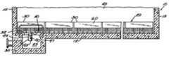
- FIG. 2is a side view of the filter of FIG. 1;
- FIG. 3is a close-up side view of the collection/distribution flume region of the filter of FIG. 1 during a backwash cycle;
- FIG. 4is a perspective view of one of the underdrain blocks of the filter of FIG. 1;
- FIG. 5is a side view of the underdrain block of FIG. 4.
- FIG. 6is a cross sectional view of the underdrain block of FIG. 5 taken along line 6 - 6 .
- FIG. 1shows a top view of a filter 10 having a base 12 and four walls 15 .
- a plurality of underdrain laterals 20are arranged side-by-side to substantially cover the base 12 .
- a collection/distribution flume 25 disposed beneath the underdrain laterals 20provides for the collection of filtrate after it passes through the filter 10 and the distribution of backwash fluid during a backwash cycle. While FIGS. 1 and 2 illustrate a rectangular filter 10 , it will be apparent to those of ordinary skill in the art that the actual shape of the filter 10 is not critical to the function of the invention.
- FIG. 2is a section view of the filter of FIG. 1 showing the base 12 and walls 15 of the filter 10 , the collection/distribution flume 25 , an underdrain lateral 20 made up of a plurality of cuboidal underdrain blocks 30 , and a conduit 35 .
- the conduit 35extends from the bottom 40 of one of the underdrain blocks 30 of the lateral 20 into the collection/distribution flume 25 .
- influentpasses through the filter media 45 disposed on top of the underdrain laterals 20 .
- the now filtered influententers one of the plurality of underdrain laterals 20 through the top surface 50 of an underdrain block 30 .
- the underdrain laterals 20channel the filtrate toward the collection/distribution flume 25 and the conduit 35 disposed therein.
- the filtrateenters the conduit 35 within the underdrain lateral 20 and flows into the collection/distribution flume 25 where it is removed from the filter 10 .
- a backwash fluid 52(shown as a liquid in FIGS. 2 and 3) enters the collection/distribution flume 25 and is forced into the conduit 35 .
- the fluidenters the underdrain laterals 20 , flows out the tops 50 of the individual underdrain blocks 30 and up through the filter media 45 .
- the backwash cyclewill be discussed in more detail below with regard to FIG. 3 .
- FIGS. 4-6show an underdrain block 30 having a plurality of top openings 55 , a plurality of walls 60 that define an inner chamber 65 and an outer region 67 , ends 70 adapted for interconnection with one another, and the conduit 35 protruding through the bottom surface 40 .
- the underdrain block 30also includes a pair of angled walls 75 , shown best in FIG. 4, extending almost the full length of the underdrain block 30 .
- the angled walls 75separate the inner chamber 65 into a primary chamber 80 , and two secondary chambers 85 . Openings (not shown) between the primary chamber 80 and secondary chambers 85 allow for the interchange of fluid therebetween.
- Other embodiments of underdrain blocksmay include several internal walls defining several chambers or no internal walls leaving only a single chamber.
- FIGS. 5 and 6show the conduit 35 extending into the primary chamber 80 of the underdrain block 30 .
- the conduit 35extends well into the primary chamber 80 .
- the conduitextends into the conduit 35 only enough to position the end of the conduit 35 flush with the inside of the bottom surface 40 .
- the conduit 35can be positioned at any elevation desired within the block 30 .
- the conduit 35extends into a chamber other than the primary chamber 80 .
- the conduit 35could extend into one of the secondary chambers 85 rather than the primary chamber 80 as illustrated in FIG. 6 .
- the conduit 35 of FIGS. 5 and 6is essentially a round pipe with one or more orifices 90 extending through its wall 92 . While a round pipe is the preferred shape, other embodiments use other shapes. For example, the conduit could be square, oval, octagonal, etc. Any shape conduit will function with the present invention, so long as it provides a sufficiently sized flow path for the filtrate and the backwash fluids.
- FIGS. 5 and 6illustrate the conduit 35 having multiple orifices 90 on two sides of the conduit 35 .
- the placement, quantity, and size of the orifices 90can vary.
- the embodiment of FIG. 5illustrates a conduit 35 having four orifices 90 , two circular and two slotted, on one side of the conduit 35 .
- the orifices 90define radial axes 1 — 1 (shown in FIG. 6) that are parallel to each other.
- the orifice radial axes 1 — 1extend along a radial line defined by the conduit 35 through the conduit wall 92 .
- FIG. 6illustrates the conduit 35 and underdrain block 30 rotated ninety degrees.
- the orifices 90 of FIG. 6are circular rather than a combination of circular and slotted.
- the orifices 90 of FIG. 6define radial axes 2 — 2 (shown in FIG. 5) that are perpendicular to the axes 1 — 1 .
- Other embodimentsmay use a single orifice 90 on only one side of the conduit 35 or a single orifice on multiple sides of the conduit.
- Still other embodimentsmay use multiple orifices 90 on multiple sides of the conduit 35 .
- orifices 90 of any shape and size and at any angle to one anotherare possible and contemplated by the invention.
- FIG. 3illustrates a magnified view of the collection/distribution flume 25 that allows for a more detailed explanation of the backwash cycle.
- backwash fluidsuch as air, water, or both
- air and waterare the most common backwash fluids used, other fluids including carbon dioxide, nitrogen, filtrate and the like, will function in a manner similar to that of air or water. Therefore, the terms air and water will be used herein to describe the backwash cycle, however, it should be understood that other fluids may be substituted for air and water and thus the terms should not be read as limiting the use of the invention to air and water alone.
- waterfills the collection/distribution flume 25 and passes through the bottom conduit opening 95 to enter the underdrain laterals 20 .
- Wateralso passes through the orifices 90 in the conduit wall to enter the underdrain laterals 20 .
- the airis free to enter the underdrain laterals 20 through the bottom conduit opening 95 as well as the orifices 90 within the conduit wall 92 .
- the orifices 90act as a metering device controlling the amount of water and air that enters the underdrain blocks 30 .
- Airenters the collection/distribution flume 25 through a dedicated air supply pipe.
- airis introduced into the backwash water flow before it enters the collection/distribution flume 25 .
- Backwash waterflows into the collection/distribution flume 25 through a backwash feed pipe. The air rises to the top of the collection/distribution flume 25 where it is trapped between the underdrain laterals 30 and the backwash water. The air thus forms an air blanket 97 above the backwash water 52 .
- the backwash water leveldecreases.
- the reduced water levelexposes the uppermost orifices 90 to the air blanket 97 , and allows air to flow into the underdrain laterals 20 .
- the orifices 90are small enough to provide sufficient air head loss to allow the collection/distribution flume 25 to act as a header providing sufficient air to all of the underdrain laterals 20 .
- the flow rate of air into the collection/distribution flume 25equals the flow rate of air through the conduit orifices 90 and the system stabilizes. If however, the air supply exceeds the passing capability of the orifices 90 , the water level will drop below the bottom conduit opening 95 , and only air will flow into the underdrain laterals 20 .
- the orifices 90can be positioned and sized to pass any volume of air desired.
Landscapes
- Chemical & Material Sciences (AREA)
- Chemical Kinetics & Catalysis (AREA)
- Filtration Of Liquid (AREA)
Abstract
Description
Claims (20)
Priority Applications (1)
| Application Number | Priority Date | Filing Date | Title |
|---|---|---|---|
| US10/192,627US6830684B2 (en) | 2002-07-10 | 2002-07-10 | Integrated liquid and gas distribution device for underdrain block laterals |
Applications Claiming Priority (1)
| Application Number | Priority Date | Filing Date | Title |
|---|---|---|---|
| US10/192,627US6830684B2 (en) | 2002-07-10 | 2002-07-10 | Integrated liquid and gas distribution device for underdrain block laterals |
Publications (2)
| Publication Number | Publication Date |
|---|---|
| US20040007541A1 US20040007541A1 (en) | 2004-01-15 |
| US6830684B2true US6830684B2 (en) | 2004-12-14 |
Family
ID=30114379
Family Applications (1)
| Application Number | Title | Priority Date | Filing Date |
|---|---|---|---|
| US10/192,627Expired - LifetimeUS6830684B2 (en) | 2002-07-10 | 2002-07-10 | Integrated liquid and gas distribution device for underdrain block laterals |
Country Status (1)
| Country | Link |
|---|---|
| US (1) | US6830684B2 (en) |
Cited By (11)
| Publication number | Priority date | Publication date | Assignee | Title |
|---|---|---|---|---|
| US20080121580A1 (en)* | 2006-11-27 | 2008-05-29 | Weatherford/ Lamb, Inc. | Geometrically Variable Filter Underdrain Header |
| US20100300954A1 (en)* | 2009-05-29 | 2010-12-02 | Roberts R Lee | Flume system for a filter system including at least one filter having a filter bed that is periodically washed with liquid, gas or a combination thereof |
| US20120103897A1 (en)* | 2010-09-21 | 2012-05-03 | Itt Manufacturing Enterprises, Inc. | Underdrain Flume Plate |
| USD684597S1 (en) | 2011-12-23 | 2013-06-18 | Xylem Water Solutions Zelienople Llc | Granular filter media retainer |
| USD687861S1 (en) | 2012-01-17 | 2013-08-13 | Xylem Water Solutions Zelienople Llc | Filter media retainer |
| US8871093B2 (en) | 2012-01-12 | 2014-10-28 | Xylem Water Solutions Zelienople Llc | Filter media retainer assembly |
| US9138665B2 (en) | 2012-07-20 | 2015-09-22 | Xylem Water Solutions Zelienople Llc | Filter media retainer assembly |
| US10059613B1 (en)* | 2012-07-23 | 2018-08-28 | Peter F. Santina | Removal of contaminants from water |
| US10913014B2 (en) | 2015-03-05 | 2021-02-09 | Xylem Water Solutions Zelienople Llc | Multiple rate filter underdrain lateral gas metering plate |
| US20230053228A1 (en)* | 2021-08-12 | 2023-02-16 | Roberts Marketing De, Inc. | Apparatus and method to prevent downward flow of liquid during a gas only washing cycle |
| US20240335770A1 (en)* | 2023-04-04 | 2024-10-10 | De Nora Water Technologies, LLC | Media retention plate for a block underdrain system |
Families Citing this family (3)
| Publication number | Priority date | Publication date | Assignee | Title |
|---|---|---|---|---|
| CA2903977C (en) | 2013-03-05 | 2020-12-01 | Xylem Water Solutions Zelienople Llc | Underdrain and method for transferring forces and directing flow |
| US10143944B2 (en) | 2016-05-04 | 2018-12-04 | Ovivo Inc. | Filter underdrain with internal air scour laterals |
| US10881990B2 (en)* | 2017-05-17 | 2021-01-05 | Xylem Water Solutions Zelienople Llc | Filter media retainer and underdrain system having a filter media retainer |
Citations (37)
| Publication number | Priority date | Publication date | Assignee | Title |
|---|---|---|---|---|
| US2710692A (en) | 1949-07-27 | 1955-06-14 | Pintsch Bamag Ag | Filter bottoms |
| US2716490A (en) | 1951-01-24 | 1955-08-30 | Eugene D Barstow | Filter construction |
| US4065391A (en) | 1975-09-08 | 1977-12-27 | Sybron Corporation | Fluid distributor |
| US4133766A (en) | 1977-03-11 | 1979-01-09 | Koppers Company, Inc. | Filter media support and containment system |
| US4214992A (en) | 1977-08-12 | 1980-07-29 | Mitsui Engineering And Shipbuilding Co., Ltd. | Water collecting and distributing apparatus disposed in a lower portion of high speed filter basin |
| US4222876A (en) | 1978-11-03 | 1980-09-16 | Englehart John D | Underdrain filter system |
| US4331542A (en) | 1980-08-01 | 1982-05-25 | Enviroquip, Inc. | Underdrain unit with air/water backwash for granular filtration system |
| US4364830A (en) | 1981-09-03 | 1982-12-21 | Roberts Filter Manufacturing Company | Filter bottom |
| US4564450A (en) | 1984-11-14 | 1986-01-14 | Dehydro Corporation | Rigid filter elements, related apparatus and methods |
| US4619765A (en) | 1984-10-10 | 1986-10-28 | Roberts Filter Manufacturing Company | Filter bottom construction |
| US4750999A (en) | 1986-06-09 | 1988-06-14 | Roberts Filter Manufacturing Company | Filter employing barrier |
| US4882053A (en) | 1988-03-24 | 1989-11-21 | Ferri Joseph E | Porous filter media support plate |
| US5019259A (en) | 1989-06-15 | 1991-05-28 | Hambley John B | Filter underdrain apparatus with partitioned distributor conduits |
| US5068034A (en) | 1990-05-03 | 1991-11-26 | Unilift Corporation | Purification underdrain with means to compensate for flow and pressure differences between laterals |
| US5087362A (en) | 1991-07-26 | 1992-02-11 | F.B. Leopold Company, Inc. | Flume distribution system with removable block |
| US5089147A (en) | 1991-05-01 | 1992-02-18 | Zimpro Passavant Environmental Systems, Inc. | Underdrain for granular medium filter |
| US5108627A (en) | 1991-02-01 | 1992-04-28 | F.B. Leopold Company, Inc. | Filter underdrain block |
| US5149427A (en) | 1991-04-03 | 1992-09-22 | The F.B. Leopold Company, Inc. | Cap for underdrains in gravity filters |
| US5156738A (en)* | 1991-06-21 | 1992-10-20 | Johnson Filtration Systems Inc. | Apparatus for uniformly distributing gas and/or liquid in an underdrain lateral system |
| US5160614A (en) | 1992-02-25 | 1992-11-03 | The F.B. Leopold Company, Inc. | Air duct block for air/water underdrain systems in gravity filters |
| US5202022A (en) | 1988-03-24 | 1993-04-13 | Ferri Joseph E | Porous filter media support plate |
| US5232592A (en) | 1991-04-03 | 1993-08-03 | The F. B. Leopold Company, Inc. | Cap for underdrains in gravity filters |
| US5269920A (en) | 1991-04-03 | 1993-12-14 | The F. B. Leopold Co., Inc. | Cap system for underdrains in gravity filters |
| US5328608A (en) | 1992-05-27 | 1994-07-12 | The F.B. Leopold Co., Inc. | Mutli-lateral filter underdrain block |
| US5332497A (en) | 1991-10-25 | 1994-07-26 | Baker Hughes Incorporated | Nozzleless underdrain for granular filtration system |
| US5413710A (en) | 1993-11-10 | 1995-05-09 | Roberts Filter Manufacturing Company | Lateral underdrain |
| US5464543A (en)* | 1992-10-16 | 1995-11-07 | Moore; Richard P. | Rapid gravity filter backwash system and filters relative thereto |
| US5489388A (en) | 1994-04-12 | 1996-02-06 | The F. B. Leopold Co., Inc. | Apparatus and method for improving gas backwash in lateral underdrains |
| US5534202A (en) | 1994-04-05 | 1996-07-09 | Roberts Filter Manufacturing Company | Air grid for underdrains and similar systems |
| US5618421A (en) | 1996-02-26 | 1997-04-08 | Infilco Degremont Inc. | Underdrain filter plate installations in automatic backwash filter systems |
| WO1997040907A1 (en) | 1996-04-26 | 1997-11-06 | Tetra Technologies, Inc. | Fluid treatment media support system |
| WO1998004332A1 (en) | 1996-07-31 | 1998-02-05 | The F.B. Leopold Co., Inc. | Apparatus for distributing gas and liquid during concurrent gas/liquid backwash in flat bottom flumes |
| US6090284A (en)* | 1998-10-13 | 2000-07-18 | Enviroquip, Inc. | Underdrain unit for granular filtration system |
| US6190568B1 (en)* | 1998-03-19 | 2001-02-20 | Tetra Process Technologies Div Of Capital Controls, A Severn Trent Services Co | Method for retrofitting a false bottom underdrain filter system |
| US6306221B1 (en)* | 1997-01-15 | 2001-10-23 | Charles T. Magliocca | Portable parts washing apparatus with centrifugal filter |
| US6423216B1 (en)* | 1999-05-04 | 2002-07-23 | Shinwoo Engineering Co., Ltd. | Biological oxidation filter system |
| US6569328B1 (en)* | 2000-11-02 | 2003-05-27 | Gary D. Haggard | Underdrain filtration system with stamped perforations |
- 2002
- 2002-07-10USUS10/192,627patent/US6830684B2/ennot_activeExpired - Lifetime
Patent Citations (39)
| Publication number | Priority date | Publication date | Assignee | Title |
|---|---|---|---|---|
| US2710692A (en) | 1949-07-27 | 1955-06-14 | Pintsch Bamag Ag | Filter bottoms |
| US2716490A (en) | 1951-01-24 | 1955-08-30 | Eugene D Barstow | Filter construction |
| US4065391A (en) | 1975-09-08 | 1977-12-27 | Sybron Corporation | Fluid distributor |
| US4133766A (en) | 1977-03-11 | 1979-01-09 | Koppers Company, Inc. | Filter media support and containment system |
| US4214992A (en) | 1977-08-12 | 1980-07-29 | Mitsui Engineering And Shipbuilding Co., Ltd. | Water collecting and distributing apparatus disposed in a lower portion of high speed filter basin |
| US4222876A (en) | 1978-11-03 | 1980-09-16 | Englehart John D | Underdrain filter system |
| US4331542A (en) | 1980-08-01 | 1982-05-25 | Enviroquip, Inc. | Underdrain unit with air/water backwash for granular filtration system |
| US4364830A (en) | 1981-09-03 | 1982-12-21 | Roberts Filter Manufacturing Company | Filter bottom |
| US4619765A (en) | 1984-10-10 | 1986-10-28 | Roberts Filter Manufacturing Company | Filter bottom construction |
| US4564450A (en) | 1984-11-14 | 1986-01-14 | Dehydro Corporation | Rigid filter elements, related apparatus and methods |
| US4750999A (en) | 1986-06-09 | 1988-06-14 | Roberts Filter Manufacturing Company | Filter employing barrier |
| US4882053A (en) | 1988-03-24 | 1989-11-21 | Ferri Joseph E | Porous filter media support plate |
| US5202022A (en) | 1988-03-24 | 1993-04-13 | Ferri Joseph E | Porous filter media support plate |
| US5019259A (en) | 1989-06-15 | 1991-05-28 | Hambley John B | Filter underdrain apparatus with partitioned distributor conduits |
| US5068034A (en) | 1990-05-03 | 1991-11-26 | Unilift Corporation | Purification underdrain with means to compensate for flow and pressure differences between laterals |
| US5108627A (en) | 1991-02-01 | 1992-04-28 | F.B. Leopold Company, Inc. | Filter underdrain block |
| US5269920A (en) | 1991-04-03 | 1993-12-14 | The F. B. Leopold Co., Inc. | Cap system for underdrains in gravity filters |
| US5149427A (en) | 1991-04-03 | 1992-09-22 | The F.B. Leopold Company, Inc. | Cap for underdrains in gravity filters |
| US5232592A (en) | 1991-04-03 | 1993-08-03 | The F. B. Leopold Company, Inc. | Cap for underdrains in gravity filters |
| US5089147A (en) | 1991-05-01 | 1992-02-18 | Zimpro Passavant Environmental Systems, Inc. | Underdrain for granular medium filter |
| US5156738A (en)* | 1991-06-21 | 1992-10-20 | Johnson Filtration Systems Inc. | Apparatus for uniformly distributing gas and/or liquid in an underdrain lateral system |
| US5087362A (en) | 1991-07-26 | 1992-02-11 | F.B. Leopold Company, Inc. | Flume distribution system with removable block |
| US5865999A (en) | 1991-10-25 | 1999-02-02 | Baker Hughes Incorporated | Nozzleless underdrain for granular filtration system |
| US5332497A (en) | 1991-10-25 | 1994-07-26 | Baker Hughes Incorporated | Nozzleless underdrain for granular filtration system |
| US5160614A (en) | 1992-02-25 | 1992-11-03 | The F.B. Leopold Company, Inc. | Air duct block for air/water underdrain systems in gravity filters |
| US5328608A (en) | 1992-05-27 | 1994-07-12 | The F.B. Leopold Co., Inc. | Mutli-lateral filter underdrain block |
| US5464543A (en)* | 1992-10-16 | 1995-11-07 | Moore; Richard P. | Rapid gravity filter backwash system and filters relative thereto |
| US5413710A (en) | 1993-11-10 | 1995-05-09 | Roberts Filter Manufacturing Company | Lateral underdrain |
| US5534202A (en) | 1994-04-05 | 1996-07-09 | Roberts Filter Manufacturing Company | Air grid for underdrains and similar systems |
| US5639384A (en) | 1994-04-12 | 1997-06-17 | The F.B. Leopold Company | Apparatus and method for improving gas backwash in lateral underdrains |
| US5489388A (en) | 1994-04-12 | 1996-02-06 | The F. B. Leopold Co., Inc. | Apparatus and method for improving gas backwash in lateral underdrains |
| US5618421A (en) | 1996-02-26 | 1997-04-08 | Infilco Degremont Inc. | Underdrain filter plate installations in automatic backwash filter systems |
| WO1997040907A1 (en) | 1996-04-26 | 1997-11-06 | Tetra Technologies, Inc. | Fluid treatment media support system |
| WO1998004332A1 (en) | 1996-07-31 | 1998-02-05 | The F.B. Leopold Co., Inc. | Apparatus for distributing gas and liquid during concurrent gas/liquid backwash in flat bottom flumes |
| US6306221B1 (en)* | 1997-01-15 | 2001-10-23 | Charles T. Magliocca | Portable parts washing apparatus with centrifugal filter |
| US6190568B1 (en)* | 1998-03-19 | 2001-02-20 | Tetra Process Technologies Div Of Capital Controls, A Severn Trent Services Co | Method for retrofitting a false bottom underdrain filter system |
| US6090284A (en)* | 1998-10-13 | 2000-07-18 | Enviroquip, Inc. | Underdrain unit for granular filtration system |
| US6423216B1 (en)* | 1999-05-04 | 2002-07-23 | Shinwoo Engineering Co., Ltd. | Biological oxidation filter system |
| US6569328B1 (en)* | 2000-11-02 | 2003-05-27 | Gary D. Haggard | Underdrain filtration system with stamped perforations |
Non-Patent Citations (1)
| Title |
|---|
| Triton Underdrain documentation, including drawings (4 pages) and brochure information (1 page). Product sold publicly prior to Jul. 1, 2001. |
Cited By (16)
| Publication number | Priority date | Publication date | Assignee | Title |
|---|---|---|---|---|
| US20080121580A1 (en)* | 2006-11-27 | 2008-05-29 | Weatherford/ Lamb, Inc. | Geometrically Variable Filter Underdrain Header |
| US20100300954A1 (en)* | 2009-05-29 | 2010-12-02 | Roberts R Lee | Flume system for a filter system including at least one filter having a filter bed that is periodically washed with liquid, gas or a combination thereof |
| US8333889B2 (en)* | 2009-05-29 | 2012-12-18 | Rg Delaware, Inc. | Flume system for a filter system including at least one filter having a filter bed that is periodically washed with liquid, gas or a combination thereof |
| US8992774B2 (en) | 2009-05-29 | 2015-03-31 | Rg Delaware, Inc. | Flume system for a filter system including at least one filter having a filter bed that is periodically washed with liquid, gas or a combination thereof |
| US9199186B2 (en)* | 2010-09-21 | 2015-12-01 | Xylem Water Solutions Zelienople Llc | Underdrain flume plate |
| US20120103897A1 (en)* | 2010-09-21 | 2012-05-03 | Itt Manufacturing Enterprises, Inc. | Underdrain Flume Plate |
| USD684597S1 (en) | 2011-12-23 | 2013-06-18 | Xylem Water Solutions Zelienople Llc | Granular filter media retainer |
| US8871093B2 (en) | 2012-01-12 | 2014-10-28 | Xylem Water Solutions Zelienople Llc | Filter media retainer assembly |
| USD687861S1 (en) | 2012-01-17 | 2013-08-13 | Xylem Water Solutions Zelienople Llc | Filter media retainer |
| US9138665B2 (en) | 2012-07-20 | 2015-09-22 | Xylem Water Solutions Zelienople Llc | Filter media retainer assembly |
| US10059613B1 (en)* | 2012-07-23 | 2018-08-28 | Peter F. Santina | Removal of contaminants from water |
| US10913014B2 (en) | 2015-03-05 | 2021-02-09 | Xylem Water Solutions Zelienople Llc | Multiple rate filter underdrain lateral gas metering plate |
| US20230053228A1 (en)* | 2021-08-12 | 2023-02-16 | Roberts Marketing De, Inc. | Apparatus and method to prevent downward flow of liquid during a gas only washing cycle |
| US12059637B2 (en)* | 2021-08-12 | 2024-08-13 | Roberts Marketing De, Inc. | Apparatus and method to prevent downward flow of liquid during a gas only washing cycle |
| US20240335770A1 (en)* | 2023-04-04 | 2024-10-10 | De Nora Water Technologies, LLC | Media retention plate for a block underdrain system |
| US12246271B2 (en)* | 2023-04-04 | 2025-03-11 | De Nora Water Technologies, LLC | Media retention plate for a block underdrain system |
Also Published As
| Publication number | Publication date |
|---|---|
| US20040007541A1 (en) | 2004-01-15 |
Similar Documents
| Publication | Publication Date | Title |
|---|---|---|
| US6830684B2 (en) | Integrated liquid and gas distribution device for underdrain block laterals | |
| US6991726B2 (en) | Filter having a media retaining plate | |
| JP3181909B2 (en) | Modular microporous filter assembly | |
| US5108627A (en) | Filter underdrain block | |
| JP7193868B2 (en) | Rectangular filter, assembly, and method for filtering | |
| JP3349015B2 (en) | Filtration device | |
| US4118322A (en) | Filtering apparatus for liquids | |
| US8070946B2 (en) | Underdrain for a filter system for filtering water or wastewater and a method of washing the filter system | |
| RU2207897C2 (en) | Filtering unit and method of cleaning filter candles of candle-type filter | |
| AU730731B2 (en) | Membrane module of a system for membrane separation, its use and process for its production | |
| JP4724300B2 (en) | Underdrain block of filter media system | |
| US5413710A (en) | Lateral underdrain | |
| US20080099412A1 (en) | System and method for uniformly distributing a fluid through a filter bed in a filter | |
| JPH06170117A (en) | Underlying water collecting module and system for filtering device | |
| US20210060465A1 (en) | Retrofitting and use of rectangular filters, assembly and method for filtration | |
| TW558450B (en) | Filter cartridge with divided filter bed for gravity flow use | |
| EP0336686B1 (en) | Granular media filters | |
| CZ295288B6 (en) | Filter for filtering beer | |
| KR20050059890A (en) | Filter of clean water device | |
| JPH0739891A (en) | Air / water distributor for biofilm filter | |
| JP7203518B2 (en) | pool filter | |
| CN115702035A (en) | Pipe system device for filtering system | |
| RU2007112179A (en) | CARTRIDGE FILTER | |
| JP2930898B2 (en) | Filtration device | |
| JPH0924254A (en) | Filtration device |
Legal Events
| Date | Code | Title | Description |
|---|---|---|---|
| AS | Assignment | Owner name:UNITED STATES FILTER CORPORATION, CALIFORNIA Free format text:ASSIGNMENT OF ASSIGNORS INTEREST;ASSIGNOR:STEGGE, JERRY;REEL/FRAME:013098/0907 Effective date:20020709 | |
| AS | Assignment | Owner name:USFILTER CORPORATION, PENNSYLVANIA Free format text:ASSIGNMENT OF ASSIGNORS INTEREST;ASSIGNOR:UNITED STATES FILTER CORPORATION;REEL/FRAME:015204/0036 Effective date:20040731 | |
| STCF | Information on status: patent grant | Free format text:PATENTED CASE | |
| CC | Certificate of correction | ||
| AS | Assignment | Owner name:SIEMENS WATER TECHNOLOGIES HOLDING CORP., PENNSYLV Free format text:CHANGE OF NAME;ASSIGNOR:USFILTER CORPORATION;REEL/FRAME:019365/0288 Effective date:20060901 | |
| FPAY | Fee payment | Year of fee payment:4 | |
| AS | Assignment | Owner name:SIEMENS INDUSTRY, INC., GEORGIA Free format text:MERGER;ASSIGNOR:SIEMENS WATER TECHNOLOGIES HOLDING CORP.;REEL/FRAME:026138/0593 Effective date:20110401 | |
| FPAY | Fee payment | Year of fee payment:8 | |
| AS | Assignment | Owner name:WESTECH ENGINEERING, INC., UTAH Free format text:ASSIGNMENT OF ASSIGNORS INTEREST;ASSIGNOR:SIEMENS INDUSTRY, INC.;REEL/FRAME:029553/0371 Effective date:20121128 | |
| FPAY | Fee payment | Year of fee payment:12 | |
| AS | Assignment | Owner name:WESTECH ENGINEERING & PROCESS EQUIPMENT LLC, UTAH Free format text:ENTITY CONVERSION FROM A CORPORATION TO A LIMITED LIABILITY COMPANY;ASSIGNOR:WESTECH ENGINEERING, INC.;REEL/FRAME:056426/0820 Effective date:20210114 | |
| AS | Assignment | Owner name:WESTECH ENGINEERING LLC, UTAH Free format text:ENTITY CONVERSION FROM A CALIFORNIA LIMITED LIABILITY COMPANY TO A UTAH LIMITED LIABILITY COMPANY;ASSIGNOR:WESTECH ENGINEERING & PROCESS EQUIPMENT LLC;REEL/FRAME:056438/0608 Effective date:20210312 | |
| AS | Assignment | Owner name:WESTECH ENGINEERING, LLC, UTAH Free format text:CHANGE OF NAME;ASSIGNOR:WESTECH ENGINEERING LLC;REEL/FRAME:056608/0995 Effective date:20210326 |