US6830571B2 - Contourable spinal staple with centralized and unilateral prongs - Google Patents
Contourable spinal staple with centralized and unilateral prongsDownload PDFInfo
- Publication number
- US6830571B2 US6830571B2US10/356,988US35698803AUS6830571B2US 6830571 B2US6830571 B2US 6830571B2US 35698803 AUS35698803 AUS 35698803AUS 6830571 B2US6830571 B2US 6830571B2
- Authority
- US
- United States
- Prior art keywords
- extending
- plate
- aperture
- fixation system
- apertures
- Prior art date
- Legal status (The legal status is an assumption and is not a legal conclusion. Google has not performed a legal analysis and makes no representation as to the accuracy of the status listed.)
- Expired - Lifetime
Links
- 210000000988bone and boneAnatomy0.000claimsdescription15
- 238000004873anchoringMethods0.000claims4
- 239000011521glassSubstances0.000abstract1
- 230000000087stabilizing effectEffects0.000abstract1
- 238000013459approachMethods0.000description6
- 230000006835compressionEffects0.000description4
- 238000007906compressionMethods0.000description4
- 208000014674injuryDiseases0.000description4
- 208000027418Wounds and injuryDiseases0.000description3
- 230000006378damageEffects0.000description3
- 206010017076FractureDiseases0.000description2
- 206010028980NeoplasmDiseases0.000description2
- 206010041541Spinal compression fractureDiseases0.000description2
- 239000012634fragmentSubstances0.000description2
- 230000004927fusionEffects0.000description2
- 239000002184metalSubstances0.000description2
- 238000000034methodMethods0.000description2
- 238000012986modificationMethods0.000description2
- 230000004048modificationEffects0.000description2
- 238000007747platingMethods0.000description2
- 206010010356Congenital anomalyDiseases0.000description1
- 206010023509KyphosisDiseases0.000description1
- 208000020339Spinal injuryDiseases0.000description1
- 230000004075alterationEffects0.000description1
- 210000003484anatomyAnatomy0.000description1
- 230000000295complement effectEffects0.000description1
- 230000002950deficientEffects0.000description1
- 238000013461designMethods0.000description1
- 238000011161developmentMethods0.000description1
- 230000000694effectsEffects0.000description1
- JGPMMRGNQUBGND-UHFFFAOYSA-NidebenoneChemical compoundCOC1=C(OC)C(=O)C(CCCCCCCCCCO)=C(C)C1=OJGPMMRGNQUBGND-UHFFFAOYSA-N0.000description1
- 229960004135idebenoneDrugs0.000description1
- 239000007943implantSubstances0.000description1
- 230000006872improvementEffects0.000description1
- 208000015181infectious diseaseDiseases0.000description1
- 238000009434installationMethods0.000description1
- 210000004705lumbosacral regionAnatomy0.000description1
- 230000001537neural effectEffects0.000description1
- 208000015122neurodegenerative diseaseDiseases0.000description1
- 230000001737promoting effectEffects0.000description1
- 230000009467reductionEffects0.000description1
- 238000002271resectionMethods0.000description1
- 210000000278spinal cordAnatomy0.000description1
- 206010041569spinal fractureDiseases0.000description1
- 210000000115thoracic cavityAnatomy0.000description1
- 230000008733traumaEffects0.000description1
- 230000000472traumatic effectEffects0.000description1
- 230000035899viabilityEffects0.000description1
- 238000012800visualizationMethods0.000description1
Images


Classifications
- A—HUMAN NECESSITIES
- A61—MEDICAL OR VETERINARY SCIENCE; HYGIENE
- A61B—DIAGNOSIS; SURGERY; IDENTIFICATION
- A61B17/00—Surgical instruments, devices or methods
- A61B17/56—Surgical instruments or methods for treatment of bones or joints; Devices specially adapted therefor
- A61B17/58—Surgical instruments or methods for treatment of bones or joints; Devices specially adapted therefor for osteosynthesis, e.g. bone plates, screws or setting implements
- A61B17/68—Internal fixation devices, including fasteners and spinal fixators, even if a part thereof projects from the skin
- A61B17/70—Spinal positioners or stabilisers, e.g. stabilisers comprising fluid filler in an implant
- A61B17/7001—Screws or hooks combined with longitudinal elements which do not contact vertebrae
- A61B17/7002—Longitudinal elements, e.g. rods
- A61B17/7004—Longitudinal elements, e.g. rods with a cross-section which varies along its length
- A61B17/7008—Longitudinal elements, e.g. rods with a cross-section which varies along its length with parts of, or attached to, the longitudinal elements, bearing against an outside of the screw or hook heads, e.g. nuts on threaded rods
- A—HUMAN NECESSITIES
- A61—MEDICAL OR VETERINARY SCIENCE; HYGIENE
- A61B—DIAGNOSIS; SURGERY; IDENTIFICATION
- A61B17/00—Surgical instruments, devices or methods
- A61B17/56—Surgical instruments or methods for treatment of bones or joints; Devices specially adapted therefor
- A61B17/58—Surgical instruments or methods for treatment of bones or joints; Devices specially adapted therefor for osteosynthesis, e.g. bone plates, screws or setting implements
- A61B17/68—Internal fixation devices, including fasteners and spinal fixators, even if a part thereof projects from the skin
- A61B17/70—Spinal positioners or stabilisers, e.g. stabilisers comprising fluid filler in an implant
- A61B17/7001—Screws or hooks combined with longitudinal elements which do not contact vertebrae
- A61B17/7044—Screws or hooks combined with longitudinal elements which do not contact vertebrae also having plates, staples or washers bearing on the vertebrae
- A—HUMAN NECESSITIES
- A61—MEDICAL OR VETERINARY SCIENCE; HYGIENE
- A61B—DIAGNOSIS; SURGERY; IDENTIFICATION
- A61B17/00—Surgical instruments, devices or methods
- A61B17/56—Surgical instruments or methods for treatment of bones or joints; Devices specially adapted therefor
- A61B17/58—Surgical instruments or methods for treatment of bones or joints; Devices specially adapted therefor for osteosynthesis, e.g. bone plates, screws or setting implements
- A61B17/68—Internal fixation devices, including fasteners and spinal fixators, even if a part thereof projects from the skin
- A61B17/80—Cortical plates, i.e. bone plates; Instruments for holding or positioning cortical plates, or for compressing bones attached to cortical plates
- A61B17/8085—Cortical plates, i.e. bone plates; Instruments for holding or positioning cortical plates, or for compressing bones attached to cortical plates with pliable or malleable elements or having a mesh-like structure, e.g. small strips
- A—HUMAN NECESSITIES
- A61—MEDICAL OR VETERINARY SCIENCE; HYGIENE
- A61B—DIAGNOSIS; SURGERY; IDENTIFICATION
- A61B17/00—Surgical instruments, devices or methods
- A61B17/56—Surgical instruments or methods for treatment of bones or joints; Devices specially adapted therefor
- A61B17/58—Surgical instruments or methods for treatment of bones or joints; Devices specially adapted therefor for osteosynthesis, e.g. bone plates, screws or setting implements
- A61B17/68—Internal fixation devices, including fasteners and spinal fixators, even if a part thereof projects from the skin
- A61B17/80—Cortical plates, i.e. bone plates; Instruments for holding or positioning cortical plates, or for compressing bones attached to cortical plates
- A61B17/809—Cortical plates, i.e. bone plates; Instruments for holding or positioning cortical plates, or for compressing bones attached to cortical plates with bone-penetrating elements, e.g. blades or prongs
Definitions
- This inventionrelates to surgical spinal implant systems, and particularly to those using spinal rods contoured for connection at various locations along the spinal column.
- posterior internal fixation proceduresfor burst fractures was a substantial improvement over early approaches of bed rest and body casts.
- Several disadvantages to posterior fixationwere, however, discovered. For example, this approach fails to reduce kyphosis or allow complete clearing of the spinal canal. Other complications include psuedoarthroses, late rod disengagement and inadequate reduction.
- Some posterior instrumentationsrequire the fusions to extend at least two levels above and below the injury, particularly at the thoracolumbar junction.
- the posterior approachis also limited in the viability for use in burst fractures because in such fractures, neural compression generally occurs from the anterior direction. Therefore, it is generally better to decompress and fuse the spine from the anterior.
- An anterior approachallows complete clearance from the spinal canal of bone fragments and for total resection of a tumor. It also permits fusion of a minimal number of motion segments. Yet in spite of these advantages, the use of anterior approaches has been limited by the risk of complications or other disadvantages.
- the Syracuse I-Platemay use rigid or semi-rigid screws in combination with a plate. But distraction or compression of the bone graft is not possible with this system.
- the CASF Plate marketed by AcroMedis designed to be used in a semi-rigid manner. This device, as well, does not permit compression or distraction of the bone graft and in addition cannot be used in a rigid construct.
- the Stafix Plating System marketed by Daruma of Taipei, Taiwanis an anterior thoracolumbar plate designed to address similar indications. This plate incorporates slots and holes as well as permitting quadrilateral placement of screws.
- the Anterior Thoracolumbar Plating System(Medtronic Sofamor Danek) is a slotted plate designed to attach to the anterior lateral aspect of the vertebral body.
- the plateallows distract and/or compression through the use of two screws and two bolts.
- FIGS. 1 to 6One such device, the Kaneda device, is shown in FIGS. 1 to 6 .
- the deviceextends fixation one vertebral level cephalad and one level caudal to the vertebra in question.
- a typical constructhas two vertebral body staples A, four vertebral screws B, two rods C, eight nuts (one on each side of a screw) and two transverse fixators F.
- Each vertebral body staple Ahas four spikes, one on each corner of the staple, to initially secure the staple to a vertebra.
- Vertebral screws Bare then placed through holes H 1 and H 2 into the cephalad and caudal vertebrae.
- Rods Care located in the holes I in each screw B with the internal nuts D loosely threaded on each rod.
- the external nuts, also identified as “D”are then threaded onto the rods. Thereafter, the surgeon tightens all nuts against each side of a screw with the surgeon applying compressive or distractive forces as required.
- the anterior and posterior rods Care then coupled with transverse fixators F.
- Specific indications for such modular devicesmay include deficient anterior bone mass due to trauma, tumor, infection, degenerative disease, congenital causes, or deformity.
- the Kaneda systemis not entirely satisfactory, largely resulting from the design of vertebral staple A.
- the stapleis used to stabilize screw B much the same way as a washer is used to stabilize a bolt in most any mechanical attachment.
- These staplesare placed on a vertebra, not a uniformly flat surface.
- the staple curvatureshould ideally match the contour of the surface of the vertebra before use. And even if the fit is perfect, it may still be unsatisfactory if the spikes on one end, say the two near hole H 1 , are pulled from the vertebra when a screw is tightened in the hole on the other end, H 2 in our example. This “rocking” effect is depicted in FIG. 7 .
- this inventionis a vertebral staple with a plate having at least two apertures to receive a spinal bolt, and at least two legs (also identifiable as prongs or spikes) integrally mounted to the bottom of the plate and wherein all legs mounted on the bottom of the plate are closer to one particular aperture for passing a spinal bolt than another aperture for passing a spinal bolt.
- this inventionis a vertebral staple with a plate having at least two apertures to receive a spinal bolt.
- the bottom of the platehas at least one leg (also identifiable as a prong or a spike) integrally mounted near the lateral edge of the plate, and at least one leg integrally mounted on the interior of the plate, with all legs mounted on the bottom of the plate closer to one particular aperture for passing a spinal bolt than another aperture for passing a spinal bolt.
- this inventionis a vertebral staple with a plate having a groove therein dividing the plate into a first portion and a second portion.
- Each of the first and second portionshave at least one aperture for passing a bone bolt through the plate and into the vertebra to which the staple is attached.
- the bottom of the first portion of the platehas at least two legs (also identifiable as prongs or spikes) integrally attached to the plate, while no legs are mounted on the bottom of the second portion of the plate.
- FIG. 1is a plan view of a prior art vertebral staple.
- FIG. 2is an exploded view of a prior bone bolt and longitudinal member.
- FIGS. 3 and 4are respectively side and plan views of a prior art spinal fixation system.
- FIGS. 5 and 6are respectively plan and side views of a prior art spinal fixation system shown attached to the spine.
- FIG. 7is a side view of a prior art vertebral staple.
- FIG. 8is a perspective view of one embodiment of the present invention.
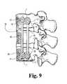
- FIGS. 9, 10 , and 11are respectively front, top, and side views of spinal fixation systems that incorporate one embodiment of the present invention.
- FIG. 8A spinal staple 1 according to the preferred embodiment of the present invention is depicted in FIG. 8 .
- Staple 1has a preferably bow-tie shaped body 2 .
- the body 2has a lateral edge 2 A and an interior 2 B.
- Body 2can generally be subdivided in two halves by a groove 11 .
- the first half 9 or wing 9contains a hole 7 and the second half 10 or wing 10 contains a hole 8 .
- Holes 7 and 8can be either threaded or unthreaded and, as illustrated in FIG. 8, are preferably substantially the same size and shape. Additionally, the holes or apertures 7 and 8 are arranged cater-cornered to one another relative to the staple body 2 , as illustrated in FIGS.
- legs 3 - 5 , prongs 3 - 5 , or spikes 3 - 5are attached to body 2 on the underside 6 of the first half 9 .
- Legs 3 and 4are unilateral with respect to body 2 . Meaning, legs 3 and 4 are commonly attached near one end of the staple so that both legs 3 and 4 are more closely adjacent legged hole 7 than non-legged hole 8 . Situated in this manner, legs 7 and 8 preferably attach toward the posterior side of the patient's vertebra, depending on the surgeon's installation.
- the third leg 5is centrally mounted in the interior of body 2 , preferably closer to legged hole 7 than non-legged hole 8 , preferably on the same side of groove 11 as legs 3 and 4 , and preferably not under groove 11 .
- the interior or inner leg or prong 5overlaps a portion of the aperture 7 in the axial direction (along the groove 11 ), and also overlaps a portion of the aperture 8 in the lateral direction (along the first and second halves 9 , 10 ).
- each of the outer legs or prongs 3 , 4is offset from the inner leg prong 5 in both the axial direction and the lateral direction.
- the outer legs or prongs 3 , 4also overlap a portion of the aperture 7 in the axial direction.
- the inner prong 5is positioned intermediate the outer prongs 3 , 4 in the lateral direction.
- the inside edge 12 of legs 3 and 4is preferably perpendicular to the underside 6 .
- the outside edge 13then tapers inwardly of the staple to intersect inside edge 12 .
- the shape of leg 5can be most anything that will work. In one embodiment, it is pyramidal and extends the same distance from underside 6 as legs 3 and 4 .
- Body 2is preferably slightly convex in shape when viewed axially along groove 11 , ends 14 and 15 being slightly bent or curved toward each other, generally at groove 11 .
- the bow-tie shape and/or the presence of groove 11 in the present inventionallows the surgeon to more easily bend and to conform staple 1 to complement the surface of the spine.
- the “pinched” middle resulting from the bow-tie shape and the presence of groove 11reduce the amount of metal that the surgeon must deform to conform the staple to the patient's vertebra if compared to prior art devices.
- the reduced metalalso affords increased visualization of the anatomy directly under the staple.
- FIGS. 9-11depict staple 1 in a spinal fixation system 16 .
- System 16has two vertebral staples, four vertebral bolts 17 or screws 17 , two rods 18 , and four clamps 19 or nuts 19 or plugs 19 to hold the rods 18 to screws 17 .
- boltor “screw” refers to any various bone fasteners, including a standard bone screw, such as those sold under the trademark CD Horizon by Medtronic Sofamor Danek.
Landscapes
- Health & Medical Sciences (AREA)
- Orthopedic Medicine & Surgery (AREA)
- Life Sciences & Earth Sciences (AREA)
- Neurology (AREA)
- Surgery (AREA)
- Heart & Thoracic Surgery (AREA)
- Engineering & Computer Science (AREA)
- Biomedical Technology (AREA)
- Nuclear Medicine, Radiotherapy & Molecular Imaging (AREA)
- Medical Informatics (AREA)
- Molecular Biology (AREA)
- Animal Behavior & Ethology (AREA)
- General Health & Medical Sciences (AREA)
- Public Health (AREA)
- Veterinary Medicine (AREA)
- Surgical Instruments (AREA)
- Prostheses (AREA)
- Orthopedics, Nursing, And Contraception (AREA)
Abstract
Description
This application is a continuation application of U.S. patent application Ser. No. 09/628,761 filed on Jul. 31, 2000, now U.S. Pat. No. 6,533,787 the contents of which are hereby incorporated by reference.
This invention relates to surgical spinal implant systems, and particularly to those using spinal rods contoured for connection at various locations along the spinal column.
Spinal fractures often occur at the thoracolumbar junction. Most of these fractures are burst injuries, which are particularly dangerous because retropulsed bone fragments can cause spinal cord or caudal equina injuries. Posterior fixation has long been the primary approach for traumatic spinal injuries of this type.
The development of posterior internal fixation procedures for burst fractures was a substantial improvement over early approaches of bed rest and body casts. Several disadvantages to posterior fixation were, however, discovered. For example, this approach fails to reduce kyphosis or allow complete clearing of the spinal canal. Other complications include psuedoarthroses, late rod disengagement and inadequate reduction. Some posterior instrumentations require the fusions to extend at least two levels above and below the injury, particularly at the thoracolumbar junction. The posterior approach is also limited in the viability for use in burst fractures because in such fractures, neural compression generally occurs from the anterior direction. Therefore, it is generally better to decompress and fuse the spine from the anterior.
There are several advantages to anterior internal fixation. An anterior approach allows complete clearance from the spinal canal of bone fragments and for total resection of a tumor. It also permits fusion of a minimal number of motion segments. Yet in spite of these advantages, the use of anterior approaches has been limited by the risk of complications or other disadvantages.
Several plate and screw systems have been designed for anterior instrumentation of the spinal column. The Syracuse I-Plate may use rigid or semi-rigid screws in combination with a plate. But distraction or compression of the bone graft is not possible with this system. The CASF Plate marketed by AcroMed is designed to be used in a semi-rigid manner. This device, as well, does not permit compression or distraction of the bone graft and in addition cannot be used in a rigid construct. The Stafix Plating System marketed by Daruma of Taipei, Taiwan is an anterior thoracolumbar plate designed to address similar indications. This plate incorporates slots and holes as well as permitting quadrilateral placement of screws. The Anterior Thoracolumbar Plating System (Medtronic Sofamor Danek) is a slotted plate designed to attach to the anterior lateral aspect of the vertebral body. The plate allows distract and/or compression through the use of two screws and two bolts.
Several modular spinal instrumentation systems have also been developed for anterior procedures. One such device, the Kaneda device, is shown in FIGS. 1 to6. As shown, the device extends fixation one vertebral level cephalad and one level caudal to the vertebra in question. A typical construct has two vertebral body staples A, four vertebral screws B, two rods C, eight nuts (one on each side of a screw) and two transverse fixators F. Each vertebral body staple A has four spikes, one on each corner of the staple, to initially secure the staple to a vertebra. Vertebral screws B are then placed through holes H1 and H2 into the cephalad and caudal vertebrae. Rods C are located in the holes I in each screw B with the internal nuts D loosely threaded on each rod. The external nuts, also identified as “D” are then threaded onto the rods. Thereafter, the surgeon tightens all nuts against each side of a screw with the surgeon applying compressive or distractive forces as required. The anterior and posterior rods C are then coupled with transverse fixators F. Specific indications for such modular devices may include deficient anterior bone mass due to trauma, tumor, infection, degenerative disease, congenital causes, or deformity.
The Kaneda system is not entirely satisfactory, largely resulting from the design of vertebral staple A. The staple is used to stabilize screw B much the same way as a washer is used to stabilize a bolt in most any mechanical attachment. These staples, however, are placed on a vertebra, not a uniformly flat surface. Hence, the staple curvature should ideally match the contour of the surface of the vertebra before use. And even if the fit is perfect, it may still be unsatisfactory if the spikes on one end, say the two near hole H1, are pulled from the vertebra when a screw is tightened in the hole on the other end, H2 in our example. This “rocking” effect is depicted in FIG.7.
Further details regarding staples in a spinal fixation device can be found in Kiyoshi Kaneda,Kaneda Anterior Spinal Instrumentation for the Thoracic and Lumbar Spine, Spinal Instrumentation, Williams & Wikins, (Baltimore, Hong Kong, London, Munich, Philadelphia, Sydney, Tokyo), pp. 413 et seq, the disclosure of which is specifically incorporated into this specification by reference.
As a result, there is a need for a vertebral staple in a modular system that can be more easily contoured to the surface of a vertebra, and that does lift spikes on one side of the staple from the vertebra when the other side is tightened. The following is one solution to this need.
In one aspect, this invention is a vertebral staple with a plate having at least two apertures to receive a spinal bolt, and at least two legs (also identifiable as prongs or spikes) integrally mounted to the bottom of the plate and wherein all legs mounted on the bottom of the plate are closer to one particular aperture for passing a spinal bolt than another aperture for passing a spinal bolt.
In another aspect, this invention is a vertebral staple with a plate having at least two apertures to receive a spinal bolt. The bottom of the plate has at least one leg (also identifiable as a prong or a spike) integrally mounted near the lateral edge of the plate, and at least one leg integrally mounted on the interior of the plate, with all legs mounted on the bottom of the plate closer to one particular aperture for passing a spinal bolt than another aperture for passing a spinal bolt.
In yet another aspect, this invention is a vertebral staple with a plate having a groove therein dividing the plate into a first portion and a second portion. Each of the first and second portions have at least one aperture for passing a bone bolt through the plate and into the vertebra to which the staple is attached. In addition, the bottom of the first portion of the plate has at least two legs (also identifiable as prongs or spikes) integrally attached to the plate, while no legs are mounted on the bottom of the second portion of the plate.
FIG. 1 is a plan view of a prior art vertebral staple.
FIG. 2 is an exploded view of a prior bone bolt and longitudinal member.
FIGS. 3 and 4 are respectively side and plan views of a prior art spinal fixation system.
FIGS. 5 and 6 are respectively plan and side views of a prior art spinal fixation system shown attached to the spine.
FIG. 7 is a side view of a prior art vertebral staple.
FIG. 8 is a perspective view of one embodiment of the present invention.
FIGS. 9,10, and11 are respectively front, top, and side views of spinal fixation systems that incorporate one embodiment of the present invention.
For the purpose of promoting an understanding of the principles of the invention, reference will now be made to the embodiments illustrated in the drawings and specific language will be used to describe the same. It will nevertheless be understood that no limitation of the scope of the invention is thereby intended, such alterations and further modifications in the illustrated device, and such further applications of the principles of the illustrated invention being contemplated as would normally occur to one skilled in this art.
Aspinal staple 1 according to the preferred embodiment of the present invention is depicted in FIG.8.Staple 1 has a preferably bow-tie shapedbody 2. Thebody 2 has alateral edge 2A and an interior2B.Body 2 can generally be subdivided in two halves by agroove 11. The first half9 or wing9 contains ahole 7 and thesecond half 10 orwing 10 contains a hole8.Holes 7 and8 can be either threaded or unthreaded and, as illustrated in FIG. 8, are preferably substantially the same size and shape. Additionally, the holes orapertures 7 and8 are arranged cater-cornered to one another relative to thestaple body 2, as illustrated in FIGS. 8 and 9, so as to be offset from one another in both a lateral direction (i.e., in a direction extending alone the first and second halves9,10) and an axial direction (i.e., in a direction extending alone the groove11).
Three legs3-5, prongs3-5, or spikes3-5 are attached tobody 2 on the underside6 of the first half9. Legs3 and4 are unilateral with respect tobody 2. Meaning, legs3 and4 are commonly attached near one end of the staple so that both legs3 and4 are more closely adjacentlegged hole 7 than non-legged hole8. Situated in this manner,legs 7 and8 preferably attach toward the posterior side of the patient's vertebra, depending on the surgeon's installation. Thethird leg 5 is centrally mounted in the interior ofbody 2, preferably closer tolegged hole 7 than non-legged hole8, preferably on the same side ofgroove 11 as legs3 and4, and preferably not undergroove 11.
As illustrated in FIGS. 8 and 9. the interior or inner leg orprong 5 overlaps a portion of theaperture 7 in the axial direction (along the groove11), and also overlaps a portion of the aperture8 in the lateral direction (along the first and second halves9,10). As also illustrated in FIGS. 8 and 9, each of the outer legs or prongs3,4 is offset from theinner leg prong 5 in both the axial direction and the lateral direction. Additionally, the outer legs or prongs3,4 also overlap a portion of theaperture 7 in the axial direction. In the illustrated embodiment, theinner prong 5 is positioned intermediate the outer prongs3,4 in the lateral direction. Theinside edge 12 of legs3 and4 is preferably perpendicular to the underside6. Theoutside edge 13 then tapers inwardly of the staple to intersectinside edge 12. The shape ofleg 5 can be most anything that will work. In one embodiment, it is pyramidal and extends the same distance from underside6 as legs3 and4.
FIGS. 9-11 depictstaple 1 in aspinal fixation system 16.System 16 has two vertebral staples, fourvertebral bolts 17 orscrews 17, tworods 18, and fourclamps 19 ornuts 19 or plugs19 to hold therods 18 toscrews 17. In this specification, the term “bolt” or “screw” refers to any various bone fasteners, including a standard bone screw, such as those sold under the trademark CD Horizon by Medtronic Sofamor Danek.
While the invention has been illustrated and described in detail and the drawings and foregoing description, the same is to be considered as illustrative and not restrictive in character, it being understood that only the preferred embodiments have been shown and described and that all changes and modifications that come within the spirit of the invention are desired to be protected.
Claims (20)
1. A spinal staple fixation system, comprising:
first and second staples adapted for engagement with respective first and second vertebral bodies, each of said first and second staples including:
a plate defining an outer edge extending about an interior region, said interior region defining first and second apertures extending therethrough and arranged cater-cornered to one another such that said first aperture is offset from said second aperture in an axial direction and in a lateral direction; and
a plurality of prongs extending from said plate, at least one of said prongs comprising an inner prong extending from said interior region of said plate, said inner prong overlapping a portion of said first aperture in said axial direction, said inner prong overlapping a portion of said second aperture in said lateral direction; and
first and second rods extending between said first and second staples to interconnect the first and second vertebral bodies.
2. The spinal staple fixation system ofclaim 1 , wherein another of said plurality of prongs extending from said plate is offset from said inner prong in said axial direction and in said lateral direction.
3. The spinal staple fixation system ofclaim 2 , wherein said another of said plurality of prongs overlaps a portion of one of said first and second apertures in said axial direction.
4. The spinal staple fixation system ofclaim 1 , wherein said inner prong is positioned closer to one of said first and second apertures than the other of said first and second apertures.
5. The spinal staple fixation system ofclaim 1 , wherein each of said plurality of prongs are positioned closer to one of said first and second apertures than the other of said first and second apertures.
6. The spinal staple fixation system ofclaim 1 , wherein said first and second apertures have a substantially identical size and shape.
7. The spinal staple fixation system ofclaim 1 , wherein each of said first and second apertures are threaded.
8. The spinal staple fixation system ofclaim 1 , wherein said inner prong has a rectangular-shaped base portion extending from said interior region of said plate and a pyramidal-shaped anchoring portion extending from said rectangular-shaped base portion.
9. The spinal staple fixation system ofclaim 1 , further comprising a plurality of bone screws, each of said bone screws extending through a respective one of said first and second apertures in said plate, said first and second rods engaged with head portions of said plurality of bone screws.
10. A spinal staple, comprising:
a plate defining an outer edge extending about an interior region, said interior region defining first and second apertures extending therethrough and arranged cater-cornered to one another such that said first aperture is offset from said second aperture in an axial direction and in a lateral direction, said plate defining a lateral curvature corresponding to an outer profile of a vertebral body to which the spinal staple may be anchored; and
a plurality of prongs extending from said plate, at least one of said prongs comprising an inner prong extending from said interior region of said plate, said inner prong overlapping a portion of said first aperture in said axial direction, said inner prong overlapping a portion of said second aperture in said lateral direction.
11. The spinal staple fixation system ofclaim 10 , wherein said inner prong has a rectangular-shaped base portion extending from said interior region of said plate and a pyramidal-shaped anchoring portion extending from said rectangular-shaped base portion.
12. A spinal staple fixation system, comprising:
first and second staples adapted for engagement with respective first and second vertebral bodies, each of said first and second staples including:
a plate defining an outer edge extending about an interior region, said interior region defining first and second apertures extending therethrough and arranged cater-cornered to one another such that said first aperture is offset from said second aperture in an axial direction and in a lateral direction; and
a plurality of prongs extending from said plate, at least one of said prongs comprising an inner prong extending from said interior region of said plate, said inner prong arranged closer to said first aperture than said second aperture in said axial direction, said inner prong arranged closer to said second aperture than said first aperture in said lateral direction; and
first and second rods extending between said first and second staples to interconnect the first and second vertebral bodies.
13. The spinal staple fixation system ofclaim 12 , wherein said inner prong overlaps a portion of said first aperture in said axial direction and a portion of said second aperture in said lateral direction.
14. The spinal staple fixation system ofclaim 12 , wherein another of said plurality of prongs extending from said plate is offset from said inner prong in said axial direction and in said lateral direction.
15. The spinal staple fixation system ofclaim 14 , wherein said another of said plurality of prongs overlaps a portion of one of said first and second apertures in said axial direction.
16. The spinal staple fixation system ofclaim 12 , wherein said first and second apertures have a substantially identical size and shape.
17. The spinal staple fixation system ofclaim 12 , wherein said inner prong has a rectangular-shaped base portion extending from said interior region of said plate and a pyramidal-shaped anchoring portion extending from said rectangular-shaped base portion.
18. The spinal staple fixation system ofclaim 12 , further comprising a plurality of bone screws, each of said bone screws extending through a respective one of said first and second apertures in said plate, said first and second rods engaged with head portions of said plurality of bone screws.
19. A spinal staple, comprising:
a plate defining an outer edge extending about an interior region, said interior region defining first and second apertures extending therethrough and arranged cater-cornered to one another such that said first aperture is offset from said second aperture in an axial direction and in a lateral direction, said plate defining a lateral curvature corresponding to an outer profile of a vertebral body to which the staple may be anchored; and
a plurality of prongs extending from said plate, at least one of said prongs comprising an inner prong extending from said interior region of said plate, said inner prong arranged closer to said first aperture than said second aperture in said axial direction, said inner prong arranged closer to said second aperture than said first aperture in said lateral direction.
20. The spinal staple fixation system ofclaim 19 , wherein said inner prong has a rectangular-shaped base portion extending from said interior region of said plate and a pyramidal-shaped anchoring portion extending from said rectangular-shaped base portion.
Priority Applications (1)
| Application Number | Priority Date | Filing Date | Title |
|---|---|---|---|
| US10/356,988US6830571B2 (en) | 2000-07-31 | 2003-02-03 | Contourable spinal staple with centralized and unilateral prongs |
Applications Claiming Priority (2)
| Application Number | Priority Date | Filing Date | Title |
|---|---|---|---|
| US09/628,761US6533787B1 (en) | 2000-07-31 | 2000-07-31 | Contourable spinal staple with centralized and unilateral prongs |
| US10/356,988US6830571B2 (en) | 2000-07-31 | 2003-02-03 | Contourable spinal staple with centralized and unilateral prongs |
Related Parent Applications (1)
| Application Number | Title | Priority Date | Filing Date |
|---|---|---|---|
| US09/628,761ContinuationUS6533787B1 (en) | 2000-07-31 | 2000-07-31 | Contourable spinal staple with centralized and unilateral prongs |
Publications (2)
| Publication Number | Publication Date |
|---|---|
| US20030120275A1 US20030120275A1 (en) | 2003-06-26 |
| US6830571B2true US6830571B2 (en) | 2004-12-14 |
Family
ID=24520188
Family Applications (2)
| Application Number | Title | Priority Date | Filing Date |
|---|---|---|---|
| US09/628,761Expired - LifetimeUS6533787B1 (en) | 2000-07-31 | 2000-07-31 | Contourable spinal staple with centralized and unilateral prongs |
| US10/356,988Expired - LifetimeUS6830571B2 (en) | 2000-07-31 | 2003-02-03 | Contourable spinal staple with centralized and unilateral prongs |
Family Applications Before (1)
| Application Number | Title | Priority Date | Filing Date |
|---|---|---|---|
| US09/628,761Expired - LifetimeUS6533787B1 (en) | 2000-07-31 | 2000-07-31 | Contourable spinal staple with centralized and unilateral prongs |
Country Status (3)
| Country | Link |
|---|---|
| US (2) | US6533787B1 (en) |
| AU (1) | AU2001279078A1 (en) |
| WO (1) | WO2002009605A2 (en) |
Cited By (99)
| Publication number | Priority date | Publication date | Assignee | Title |
|---|---|---|---|---|
| US20040097927A1 (en)* | 2001-02-13 | 2004-05-20 | Yeung Jeffrey E. | Intervertebral disc repair |
| US20040111089A1 (en)* | 2002-12-04 | 2004-06-10 | Stevens Peter M. | Bone alignment implant and method of use |
| US20040133207A1 (en)* | 2002-10-11 | 2004-07-08 | Abdou M. Samy | Distraction screw for skeletal surgery and method of use |
| US20050004573A1 (en)* | 2003-04-18 | 2005-01-06 | M. Samy Abdou | Bone fixation system and method of implantation |
| US20050288669A1 (en)* | 2004-06-14 | 2005-12-29 | Abdou M S | Occipito fixation system and method of use |
| US20060229615A1 (en)* | 2005-02-18 | 2006-10-12 | Abdou M S | Devices and methods for dynamic fixation of skeletal structure |
| US20070093834A1 (en)* | 2005-10-06 | 2007-04-26 | Stevens Peter M | Bone alignment implant and method of use |
| US20070106383A1 (en)* | 2005-10-03 | 2007-05-10 | Abdou M S | Devices and methods for inter-vertebral orthopedic device placement |
| US20070123916A1 (en)* | 2005-10-25 | 2007-05-31 | Brainlab Ag | Non-penetrating fixing device |
| US20070239278A1 (en)* | 2006-04-06 | 2007-10-11 | Sdgi Holdings, Inc. | Intervertebral prosthetic devices and methods |
| US20080058810A1 (en)* | 2003-01-10 | 2008-03-06 | Abdou M S | Bone screw systems and methods of use |
| US20080140136A1 (en)* | 2003-06-18 | 2008-06-12 | Jackson Roger P | Polyaxial bone screw with cam capture |
| US20090024171A1 (en)* | 2007-07-19 | 2009-01-22 | Vincent Leone | Anatomical Anterior Vertebral Plating System |
| US20090099602A1 (en)* | 2007-09-11 | 2009-04-16 | Kamran Aflatoon | Method of lateral facet approach, decompression and fusion using screws and staples as well as arthroplasty |
| US20090149884A1 (en)* | 2007-08-02 | 2009-06-11 | Redyns Medical, Llc | System and method for bridge anchor tendon attachment |
| US7662175B2 (en) | 2003-06-18 | 2010-02-16 | Jackson Roger P | Upload shank swivel head bone screw spinal implant |
| US7766915B2 (en) | 2004-02-27 | 2010-08-03 | Jackson Roger P | Dynamic fixation assemblies with inner core and outer coil-like member |
| US7875065B2 (en) | 2004-11-23 | 2011-01-25 | Jackson Roger P | Polyaxial bone screw with multi-part shank retainer and pressure insert |
| US7901437B2 (en) | 2007-01-26 | 2011-03-08 | Jackson Roger P | Dynamic stabilization member with molded connection |
| US7942910B2 (en) | 2007-05-16 | 2011-05-17 | Ortho Innovations, Llc | Polyaxial bone screw |
| US7942911B2 (en) | 2007-05-16 | 2011-05-17 | Ortho Innovations, Llc | Polyaxial bone screw |
| US7942909B2 (en) | 2009-08-13 | 2011-05-17 | Ortho Innovations, Llc | Thread-thru polyaxial pedicle screw system |
| US7947065B2 (en) | 2008-11-14 | 2011-05-24 | Ortho Innovations, Llc | Locking polyaxial ball and socket fastener |
| US7951170B2 (en) | 2007-05-31 | 2011-05-31 | Jackson Roger P | Dynamic stabilization connecting member with pre-tensioned solid core |
| US7951173B2 (en) | 2007-05-16 | 2011-05-31 | Ortho Innovations, Llc | Pedicle screw implant system |
| US7967850B2 (en) | 2003-06-18 | 2011-06-28 | Jackson Roger P | Polyaxial bone anchor with helical capture connection, insert and dual locking assembly |
| US8012177B2 (en) | 2007-02-12 | 2011-09-06 | Jackson Roger P | Dynamic stabilization assembly with frusto-conical connection |
| US8066739B2 (en) | 2004-02-27 | 2011-11-29 | Jackson Roger P | Tool system for dynamic spinal implants |
| US8075603B2 (en) | 2008-11-14 | 2011-12-13 | Ortho Innovations, Llc | Locking polyaxial ball and socket fastener |
| US8092500B2 (en) | 2007-05-01 | 2012-01-10 | Jackson Roger P | Dynamic stabilization connecting member with floating core, compression spacer and over-mold |
| US8092502B2 (en) | 2003-04-09 | 2012-01-10 | Jackson Roger P | Polyaxial bone screw with uploaded threaded shank and method of assembly and use |
| US8100915B2 (en) | 2004-02-27 | 2012-01-24 | Jackson Roger P | Orthopedic implant rod reduction tool set and method |
| US8105368B2 (en) | 2005-09-30 | 2012-01-31 | Jackson Roger P | Dynamic stabilization connecting member with slitted core and outer sleeve |
| US8109980B2 (en) | 2005-04-19 | 2012-02-07 | Kyphon Sarl | Antero-lateral plating systems and methods for spinal stabilization |
| US8128667B2 (en) | 2002-09-06 | 2012-03-06 | Jackson Roger P | Anti-splay medical implant closure with multi-surface removal aperture |
| US8137386B2 (en) | 2003-08-28 | 2012-03-20 | Jackson Roger P | Polyaxial bone screw apparatus |
| US8152810B2 (en) | 2004-11-23 | 2012-04-10 | Jackson Roger P | Spinal fixation tool set and method |
| US8172855B2 (en) | 2004-11-24 | 2012-05-08 | Abdou M S | Devices and methods for inter-vertebral orthopedic device placement |
| US8197518B2 (en) | 2007-05-16 | 2012-06-12 | Ortho Innovations, Llc | Thread-thru polyaxial pedicle screw system |
| US8257402B2 (en) | 2002-09-06 | 2012-09-04 | Jackson Roger P | Closure for rod receiving orthopedic implant having left handed thread removal |
| US8273109B2 (en) | 2002-09-06 | 2012-09-25 | Jackson Roger P | Helical wound mechanically interlocking mating guide and advancement structure |
| US8292926B2 (en) | 2005-09-30 | 2012-10-23 | Jackson Roger P | Dynamic stabilization connecting member with elastic core and outer sleeve |
| US8303630B2 (en) | 2006-07-27 | 2012-11-06 | Samy Abdou | Devices and methods for the minimally invasive treatment of spinal stenosis |
| US8308782B2 (en) | 2004-11-23 | 2012-11-13 | Jackson Roger P | Bone anchors with longitudinal connecting member engaging inserts and closures for fixation and optional angulation |
| US8343194B2 (en) | 2007-08-20 | 2013-01-01 | Kamran Aflatoon | Anterior cervical staple |
| US8353932B2 (en) | 2005-09-30 | 2013-01-15 | Jackson Roger P | Polyaxial bone anchor assembly with one-piece closure, pressure insert and plastic elongate member |
| US8366745B2 (en) | 2007-05-01 | 2013-02-05 | Jackson Roger P | Dynamic stabilization assembly having pre-compressed spacers with differential displacements |
| US8366753B2 (en) | 2003-06-18 | 2013-02-05 | Jackson Roger P | Polyaxial bone screw assembly with fixed retaining structure |
| US8377100B2 (en) | 2000-12-08 | 2013-02-19 | Roger P. Jackson | Closure for open-headed medical implant |
| US8377102B2 (en) | 2003-06-18 | 2013-02-19 | Roger P. Jackson | Polyaxial bone anchor with spline capture connection and lower pressure insert |
| US8398682B2 (en) | 2003-06-18 | 2013-03-19 | Roger P. Jackson | Polyaxial bone screw assembly |
| US8414616B2 (en) | 2006-09-12 | 2013-04-09 | Pioneer Surgical Technology, Inc. | Mounting devices for fixation devices and insertion instruments used therewith |
| US8444681B2 (en) | 2009-06-15 | 2013-05-21 | Roger P. Jackson | Polyaxial bone anchor with pop-on shank, friction fit retainer and winged insert |
| US8475498B2 (en) | 2007-01-18 | 2013-07-02 | Roger P. Jackson | Dynamic stabilization connecting member with cord connection |
| US8545538B2 (en) | 2005-12-19 | 2013-10-01 | M. Samy Abdou | Devices and methods for inter-vertebral orthopedic device placement |
| US8556938B2 (en) | 2009-06-15 | 2013-10-15 | Roger P. Jackson | Polyaxial bone anchor with non-pivotable retainer and pop-on shank, some with friction fit |
| US8591515B2 (en) | 2004-11-23 | 2013-11-26 | Roger P. Jackson | Spinal fixation tool set and method |
| US8814913B2 (en) | 2002-09-06 | 2014-08-26 | Roger P Jackson | Helical guide and advancement flange with break-off extensions |
| US8814911B2 (en) | 2003-06-18 | 2014-08-26 | Roger P. Jackson | Polyaxial bone screw with cam connection and lock and release insert |
| US8845649B2 (en) | 2004-09-24 | 2014-09-30 | Roger P. Jackson | Spinal fixation tool set and method for rod reduction and fastener insertion |
| US8870920B2 (en) | 2005-10-07 | 2014-10-28 | M. Samy Abdou | Devices and methods for inter-vertebral orthopedic device placement |
| US8876868B2 (en) | 2002-09-06 | 2014-11-04 | Roger P. Jackson | Helical guide and advancement flange with radially loaded lip |
| US8876874B2 (en) | 2006-08-21 | 2014-11-04 | M. Samy Abdou | Bone screw systems and methods of use |
| US8911477B2 (en) | 2007-10-23 | 2014-12-16 | Roger P. Jackson | Dynamic stabilization member with end plate support and cable core extension |
| US8911479B2 (en) | 2012-01-10 | 2014-12-16 | Roger P. Jackson | Multi-start closures for open implants |
| US8936623B2 (en) | 2003-06-18 | 2015-01-20 | Roger P. Jackson | Polyaxial bone screw assembly |
| US8979904B2 (en) | 2007-05-01 | 2015-03-17 | Roger P Jackson | Connecting member with tensioned cord, low profile rigid sleeve and spacer with torsion control |
| US8998959B2 (en) | 2009-06-15 | 2015-04-07 | Roger P Jackson | Polyaxial bone anchors with pop-on shank, fully constrained friction fit retainer and lock and release insert |
| US9050139B2 (en) | 2004-02-27 | 2015-06-09 | Roger P. Jackson | Orthopedic implant rod reduction tool set and method |
| US9168069B2 (en) | 2009-06-15 | 2015-10-27 | Roger P. Jackson | Polyaxial bone anchor with pop-on shank and winged insert with lower skirt for engaging a friction fit retainer |
| US9198695B2 (en) | 2010-08-30 | 2015-12-01 | Zimmer Spine, Inc. | Polyaxial pedicle screw |
| US9216041B2 (en) | 2009-06-15 | 2015-12-22 | Roger P. Jackson | Spinal connecting members with tensioned cords and rigid sleeves for engaging compression inserts |
| US9216039B2 (en) | 2004-02-27 | 2015-12-22 | Roger P. Jackson | Dynamic spinal stabilization assemblies, tool set and method |
| US9414863B2 (en) | 2005-02-22 | 2016-08-16 | Roger P. Jackson | Polyaxial bone screw with spherical capture, compression insert and alignment and retention structures |
| US9451989B2 (en) | 2007-01-18 | 2016-09-27 | Roger P Jackson | Dynamic stabilization members with elastic and inelastic sections |
| US9453526B2 (en) | 2013-04-30 | 2016-09-27 | Degen Medical, Inc. | Bottom-loading anchor assembly |
| US9480517B2 (en) | 2009-06-15 | 2016-11-01 | Roger P. Jackson | Polyaxial bone anchor with pop-on shank, shank, friction fit retainer, winged insert and low profile edge lock |
| US9743957B2 (en) | 2004-11-10 | 2017-08-29 | Roger P. Jackson | Polyaxial bone screw with shank articulation pressure insert and method |
| US9867714B1 (en) | 2011-09-23 | 2018-01-16 | Samy Abdou | Spinal fixation devices and methods of use |
| US9907574B2 (en) | 2008-08-01 | 2018-03-06 | Roger P. Jackson | Polyaxial bone anchors with pop-on shank, friction fit fully restrained retainer, insert and tool receiving features |
| US9980753B2 (en) | 2009-06-15 | 2018-05-29 | Roger P Jackson | pivotal anchor with snap-in-place insert having rotation blocking extensions |
| US10039578B2 (en) | 2003-12-16 | 2018-08-07 | DePuy Synthes Products, Inc. | Methods and devices for minimally invasive spinal fixation element placement |
| US10111757B2 (en) | 2012-10-22 | 2018-10-30 | Cogent Spine, LLC | Devices and methods for spinal stabilization and instrumentation |
| US10194951B2 (en) | 2005-05-10 | 2019-02-05 | Roger P. Jackson | Polyaxial bone anchor with compound articulation and pop-on shank |
| US10258382B2 (en) | 2007-01-18 | 2019-04-16 | Roger P. Jackson | Rod-cord dynamic connection assemblies with slidable bone anchor attachment members along the cord |
| US10299839B2 (en) | 2003-12-16 | 2019-05-28 | Medos International Sárl | Percutaneous access devices and bone anchor assemblies |
| US10363070B2 (en) | 2009-06-15 | 2019-07-30 | Roger P. Jackson | Pivotal bone anchor assemblies with pressure inserts and snap on articulating retainers |
| US10383660B2 (en) | 2007-05-01 | 2019-08-20 | Roger P. Jackson | Soft stabilization assemblies with pretensioned cords |
| US10543107B2 (en) | 2009-12-07 | 2020-01-28 | Samy Abdou | Devices and methods for minimally invasive spinal stabilization and instrumentation |
| US10548740B1 (en) | 2016-10-25 | 2020-02-04 | Samy Abdou | Devices and methods for vertebral bone realignment |
| US10695105B2 (en) | 2012-08-28 | 2020-06-30 | Samy Abdou | Spinal fixation devices and methods of use |
| US10729469B2 (en) | 2006-01-09 | 2020-08-04 | Roger P. Jackson | Flexible spinal stabilization assembly with spacer having off-axis core member |
| WO2020190883A1 (en)* | 2019-03-19 | 2020-09-24 | Crossroads Extremity Systems, Llc | Modular bone implant devices and means of insertion |
| US10857003B1 (en) | 2015-10-14 | 2020-12-08 | Samy Abdou | Devices and methods for vertebral stabilization |
| US10973648B1 (en) | 2016-10-25 | 2021-04-13 | Samy Abdou | Devices and methods for vertebral bone realignment |
| US11006982B2 (en) | 2012-02-22 | 2021-05-18 | Samy Abdou | Spinous process fixation devices and methods of use |
| US11179248B2 (en) | 2018-10-02 | 2021-11-23 | Samy Abdou | Devices and methods for spinal implantation |
| US11419642B2 (en) | 2003-12-16 | 2022-08-23 | Medos International Sarl | Percutaneous access devices and bone anchor assemblies |
| US12383311B2 (en) | 2010-05-14 | 2025-08-12 | Roger P. Jackson | Pivotal bone anchor assembly and method for use thereof |
Families Citing this family (38)
| Publication number | Priority date | Publication date | Assignee | Title |
|---|---|---|---|---|
| US7833250B2 (en) | 2004-11-10 | 2010-11-16 | Jackson Roger P | Polyaxial bone screw with helically wound capture connection |
| US6899714B2 (en)* | 2001-10-03 | 2005-05-31 | Vaughan Medical Technologies, Inc. | Vertebral stabilization assembly and method |
| FR2835736B1 (en)* | 2002-02-13 | 2004-10-29 | Hassan Razian | SYSTEM FOR SOLIDARIZING A BAR OR THE LIKE WITH AT LEAST ONE VERTEBRA |
| DE20207847U1 (en)* | 2002-05-21 | 2002-10-10 | Metz-Stavenhagen, Peter, Dr.med., 34537 Bad Wildungen | Device for setting up a human or animal spine and fastening element therefor |
| US7175624B2 (en) | 2002-12-31 | 2007-02-13 | Depuy Spine, Inc. | Bone plate and screw system allowing bi-directional assembly |
| US7048739B2 (en) | 2002-12-31 | 2006-05-23 | Depuy Spine, Inc. | Bone plate and resilient screw system allowing bi-directional assembly |
| US7914561B2 (en) | 2002-12-31 | 2011-03-29 | Depuy Spine, Inc. | Resilient bone plate and screw system allowing bi-directional assembly |
| US7341591B2 (en) | 2003-01-30 | 2008-03-11 | Depuy Spine, Inc. | Anterior buttress staple |
| US20040236333A1 (en)* | 2003-03-21 | 2004-11-25 | Lin Paul S. | Uniplate cervical device |
| US7377923B2 (en) | 2003-05-22 | 2008-05-27 | Alphatec Spine, Inc. | Variable angle spinal screw assembly |
| TW200519119A (en)* | 2003-10-10 | 2005-06-16 | Otsuka Chemical Co Ltd | PENAM crystal and process for producing the same |
| US7883510B2 (en)* | 2004-08-27 | 2011-02-08 | Depuy Spine, Inc. | Vertebral staples and insertion tools |
| US8926672B2 (en) | 2004-11-10 | 2015-01-06 | Roger P. Jackson | Splay control closure for open bone anchor |
| WO2006057837A1 (en) | 2004-11-23 | 2006-06-01 | Jackson Roger P | Spinal fixation tool attachment structure |
| US7892260B2 (en)* | 2006-10-06 | 2011-02-22 | Depuy Spine, Inc. | Unilateral placement |
| US8388663B2 (en) | 2007-09-13 | 2013-03-05 | Stryker Spine | Dynamic cervical plate |
| US8821546B2 (en) | 2007-11-06 | 2014-09-02 | Stanus Investments, Inc. | Vertebral screw arrangement with locking pin |
| EP2135562B1 (en)* | 2008-06-20 | 2015-09-09 | Arthrex, Inc. | Wedged profile plate |
| US20100094358A1 (en)* | 2008-10-10 | 2010-04-15 | K2M, Inc. | Spinal staple |
| US9668771B2 (en) | 2009-06-15 | 2017-06-06 | Roger P Jackson | Soft stabilization assemblies with off-set connector |
| US11229457B2 (en) | 2009-06-15 | 2022-01-25 | Roger P. Jackson | Pivotal bone anchor assembly with insert tool deployment |
| US8758347B2 (en)* | 2010-03-19 | 2014-06-24 | Nextremity Solutions, Inc. | Dynamic bone plate |
| US8992579B1 (en) | 2011-03-08 | 2015-03-31 | Nuvasive, Inc. | Lateral fixation constructs and related methods |
| US9585697B2 (en)* | 2011-04-01 | 2017-03-07 | Rebecca Elizabeth Stachniak | Posterior stabilization systems and methods |
| US9060815B1 (en) | 2012-03-08 | 2015-06-23 | Nuvasive, Inc. | Systems and methods for performing spine surgery |
| US8911478B2 (en) | 2012-11-21 | 2014-12-16 | Roger P. Jackson | Splay control closure for open bone anchor |
| US10058354B2 (en) | 2013-01-28 | 2018-08-28 | Roger P. Jackson | Pivotal bone anchor assembly with frictional shank head seating surfaces |
| US8852239B2 (en) | 2013-02-15 | 2014-10-07 | Roger P Jackson | Sagittal angle screw with integral shank and receiver |
| US9517089B1 (en) | 2013-10-08 | 2016-12-13 | Nuvasive, Inc. | Bone anchor with offset rod connector |
| US9566092B2 (en) | 2013-10-29 | 2017-02-14 | Roger P. Jackson | Cervical bone anchor with collet retainer and outer locking sleeve |
| US9717533B2 (en) | 2013-12-12 | 2017-08-01 | Roger P. Jackson | Bone anchor closure pivot-splay control flange form guide and advancement structure |
| US9451993B2 (en) | 2014-01-09 | 2016-09-27 | Roger P. Jackson | Bi-radial pop-on cervical bone anchor |
| US9597119B2 (en) | 2014-06-04 | 2017-03-21 | Roger P. Jackson | Polyaxial bone anchor with polymer sleeve |
| US10064658B2 (en) | 2014-06-04 | 2018-09-04 | Roger P. Jackson | Polyaxial bone anchor with insert guides |
| DE102014117175A1 (en)* | 2014-11-24 | 2016-05-25 | Aesculap Ag | Pedicle screw system and spine stabilization system |
| EP3045130B1 (en)* | 2015-01-14 | 2018-09-26 | Königsee Implantate GmbH | Implant for temporary epiphysiodesis or hemiepiphysiodesis |
| EP3675754B1 (en) | 2017-08-30 | 2024-06-26 | Zimmer Biomet Spine, Inc. | Dynamic stabilization system |
| US12082849B2 (en)* | 2019-04-12 | 2024-09-10 | Orthopediatrics Corp. | Dual tether support of vertebra |
Citations (16)
| Publication number | Priority date | Publication date | Assignee | Title |
|---|---|---|---|---|
| US4047524A (en) | 1975-04-28 | 1977-09-13 | Downs Surgical Limited | Surgical implant spinal staple |
| USD274095S (en)* | 1982-02-18 | 1984-05-29 | Howmedica, Inc. | Femoral drill jig for the implantation of a prosthetic knee |
| US4651724A (en) | 1984-05-18 | 1987-03-24 | Technomed Gmk | Bone joining plate |
| US4960420A (en)* | 1988-08-23 | 1990-10-02 | Marlowe Goble E | Channel ligament clamp and system |
| US5108395A (en) | 1989-09-18 | 1992-04-28 | Societe De Fabrication De Materiel Orthopedique - Sofamor | Implant for anterior dorsolumbar spinal osteosynthesis, intended for the correction of kyphoses |
| US5147361A (en) | 1989-11-29 | 1992-09-15 | Asahi Kogaku Kogyo Kabushiki Kaisha | Vertebral connecting plate |
| DE9217768U1 (en) | 1992-12-29 | 1993-05-27 | Chiropro GmbH medizinisch-technische Produkte, 8510 Fürth | Osteosynthesis plate |
| US5306275A (en) | 1992-12-31 | 1994-04-26 | Bryan Donald W | Lumbar spine fixation apparatus and method |
| US5314427A (en)* | 1992-10-13 | 1994-05-24 | Marlowe Goble E | Channel ligament clamp |
| EP0615728A2 (en) | 1993-02-16 | 1994-09-21 | MIKHAIL, Michael W.E. | Orthopaedic reconstruction plate |
| US5487741A (en) | 1992-11-16 | 1996-01-30 | Taguchi Medical Co., Ltd. | Bone plate |
| US5603714A (en) | 1993-12-15 | 1997-02-18 | Mizuho Ika Kogyo Kabushiki Kaisha | Instrument for anterior correction of scoliosis or the like |
| US5616144A (en) | 1992-11-25 | 1997-04-01 | Codman & Shurtleff, Inc. | Osteosynthesis plate system |
| US5620443A (en) | 1995-01-25 | 1997-04-15 | Danek Medical, Inc. | Anterior screw-rod connector |
| EP0820730A1 (en) | 1996-07-22 | 1998-01-28 | Euros | Spinal osteosynthesis plate |
| US5899904A (en) | 1998-10-19 | 1999-05-04 | Third Milennium Engineering, Llc | Compression locking vertebral body screw, staple, and rod assembly |
- 2000
- 2000-07-31USUS09/628,761patent/US6533787B1/ennot_activeExpired - Lifetime
- 2001
- 2001-07-30AUAU2001279078Apatent/AU2001279078A1/ennot_activeAbandoned
- 2001-07-30WOPCT/US2001/023845patent/WO2002009605A2/enactiveApplication Filing
- 2003
- 2003-02-03USUS10/356,988patent/US6830571B2/ennot_activeExpired - Lifetime
Patent Citations (16)
| Publication number | Priority date | Publication date | Assignee | Title |
|---|---|---|---|---|
| US4047524A (en) | 1975-04-28 | 1977-09-13 | Downs Surgical Limited | Surgical implant spinal staple |
| USD274095S (en)* | 1982-02-18 | 1984-05-29 | Howmedica, Inc. | Femoral drill jig for the implantation of a prosthetic knee |
| US4651724A (en) | 1984-05-18 | 1987-03-24 | Technomed Gmk | Bone joining plate |
| US4960420A (en)* | 1988-08-23 | 1990-10-02 | Marlowe Goble E | Channel ligament clamp and system |
| US5108395A (en) | 1989-09-18 | 1992-04-28 | Societe De Fabrication De Materiel Orthopedique - Sofamor | Implant for anterior dorsolumbar spinal osteosynthesis, intended for the correction of kyphoses |
| US5147361A (en) | 1989-11-29 | 1992-09-15 | Asahi Kogaku Kogyo Kabushiki Kaisha | Vertebral connecting plate |
| US5314427A (en)* | 1992-10-13 | 1994-05-24 | Marlowe Goble E | Channel ligament clamp |
| US5487741A (en) | 1992-11-16 | 1996-01-30 | Taguchi Medical Co., Ltd. | Bone plate |
| US5616144A (en) | 1992-11-25 | 1997-04-01 | Codman & Shurtleff, Inc. | Osteosynthesis plate system |
| DE9217768U1 (en) | 1992-12-29 | 1993-05-27 | Chiropro GmbH medizinisch-technische Produkte, 8510 Fürth | Osteosynthesis plate |
| US5306275A (en) | 1992-12-31 | 1994-04-26 | Bryan Donald W | Lumbar spine fixation apparatus and method |
| EP0615728A2 (en) | 1993-02-16 | 1994-09-21 | MIKHAIL, Michael W.E. | Orthopaedic reconstruction plate |
| US5603714A (en) | 1993-12-15 | 1997-02-18 | Mizuho Ika Kogyo Kabushiki Kaisha | Instrument for anterior correction of scoliosis or the like |
| US5620443A (en) | 1995-01-25 | 1997-04-15 | Danek Medical, Inc. | Anterior screw-rod connector |
| EP0820730A1 (en) | 1996-07-22 | 1998-01-28 | Euros | Spinal osteosynthesis plate |
| US5899904A (en) | 1998-10-19 | 1999-05-04 | Third Milennium Engineering, Llc | Compression locking vertebral body screw, staple, and rod assembly |
Non-Patent Citations (4)
| Title |
|---|
| Anterior Spinal Fixation After Lumbar Corpectomy, by Thomas Zdeblick, M.D., Osamu Shirado, M.D., Paul C. McAfee, M.D., Henry DeGroot, M.D. & Karen E. Warden, (C) 1991 by the Journal of Bone and Joint surgery, Incorporated . |
| Anterior Spinal Fixation After Lumbar Corpectomy, by Thomas Zdeblick, M.D., Osamu Shirado, M.D., Paul C. McAfee, M.D., Henry DeGroot, M.D. & Karen E. Warden, © 1991 by the Journal of Bone and Joint surgery, Incorporated . |
| Kaneda Anterior Spinal Instrumentation for the Thoracic and Lumbar Spine, by Kiyoshi Kaneda, pp. 413-422. |
| Kaneda Anterior Spinal Instrumentation System and Kaneda Anterior Spinal Screws, by AcroMed Corporation, p. B-12. |
Cited By (185)
| Publication number | Priority date | Publication date | Assignee | Title |
|---|---|---|---|---|
| US8377100B2 (en) | 2000-12-08 | 2013-02-19 | Roger P. Jackson | Closure for open-headed medical implant |
| US20040097927A1 (en)* | 2001-02-13 | 2004-05-20 | Yeung Jeffrey E. | Intervertebral disc repair |
| US8814913B2 (en) | 2002-09-06 | 2014-08-26 | Roger P Jackson | Helical guide and advancement flange with break-off extensions |
| US8273109B2 (en) | 2002-09-06 | 2012-09-25 | Jackson Roger P | Helical wound mechanically interlocking mating guide and advancement structure |
| US8591552B2 (en) | 2002-09-06 | 2013-11-26 | Roger P. Jackson | Anti-splay medical implant closure with multi-surface removal aperture |
| US8876868B2 (en) | 2002-09-06 | 2014-11-04 | Roger P. Jackson | Helical guide and advancement flange with radially loaded lip |
| US8282673B2 (en) | 2002-09-06 | 2012-10-09 | Jackson Roger P | Anti-splay medical implant closure with multi-surface removal aperture |
| US8257402B2 (en) | 2002-09-06 | 2012-09-04 | Jackson Roger P | Closure for rod receiving orthopedic implant having left handed thread removal |
| US8128667B2 (en) | 2002-09-06 | 2012-03-06 | Jackson Roger P | Anti-splay medical implant closure with multi-surface removal aperture |
| US20090177238A1 (en)* | 2002-10-11 | 2009-07-09 | Abdou M Samy | Distraction screw for skeletal surgery and method of use |
| US20040133207A1 (en)* | 2002-10-11 | 2004-07-08 | Abdou M. Samy | Distraction screw for skeletal surgery and method of use |
| US7476228B2 (en) | 2002-10-11 | 2009-01-13 | Abdou M Samy | Distraction screw for skeletal surgery and method of use |
| US20040111089A1 (en)* | 2002-12-04 | 2004-06-10 | Stevens Peter M. | Bone alignment implant and method of use |
| US8641742B2 (en) | 2002-12-04 | 2014-02-04 | Peter M. Stevens | Methods for bone alignment |
| US8133230B2 (en)* | 2002-12-04 | 2012-03-13 | Peter M. Stevens | Bone alignment implant and method of use |
| US7811312B2 (en) | 2002-12-04 | 2010-10-12 | Morphographics, Lc | Bone alignment implant and method of use |
| US20080058810A1 (en)* | 2003-01-10 | 2008-03-06 | Abdou M S | Bone screw systems and methods of use |
| US10952777B2 (en) | 2003-04-09 | 2021-03-23 | Roger P. Jackson | Pivotal bone screw assembly with receiver having threaded open channel and lower opening |
| US8092502B2 (en) | 2003-04-09 | 2012-01-10 | Jackson Roger P | Polyaxial bone screw with uploaded threaded shank and method of assembly and use |
| US8540753B2 (en) | 2003-04-09 | 2013-09-24 | Roger P. Jackson | Polyaxial bone screw with uploaded threaded shank and method of assembly and use |
| US7291152B2 (en)* | 2003-04-18 | 2007-11-06 | Abdou M Samy | Bone fixation system and method of implantation |
| US20050004573A1 (en)* | 2003-04-18 | 2005-01-06 | M. Samy Abdou | Bone fixation system and method of implantation |
| US8936623B2 (en) | 2003-06-18 | 2015-01-20 | Roger P. Jackson | Polyaxial bone screw assembly |
| US7967850B2 (en) | 2003-06-18 | 2011-06-28 | Jackson Roger P | Polyaxial bone anchor with helical capture connection, insert and dual locking assembly |
| USRE46431E1 (en) | 2003-06-18 | 2017-06-13 | Roger P Jackson | Polyaxial bone anchor with helical capture connection, insert and dual locking assembly |
| US8636769B2 (en) | 2003-06-18 | 2014-01-28 | Roger P. Jackson | Polyaxial bone screw with shank-retainer insert capture |
| US8366753B2 (en) | 2003-06-18 | 2013-02-05 | Jackson Roger P | Polyaxial bone screw assembly with fixed retaining structure |
| US20080140136A1 (en)* | 2003-06-18 | 2008-06-12 | Jackson Roger P | Polyaxial bone screw with cam capture |
| US8377102B2 (en) | 2003-06-18 | 2013-02-19 | Roger P. Jackson | Polyaxial bone anchor with spline capture connection and lower pressure insert |
| US9144444B2 (en) | 2003-06-18 | 2015-09-29 | Roger P Jackson | Polyaxial bone anchor with helical capture connection, insert and dual locking assembly |
| US8398682B2 (en) | 2003-06-18 | 2013-03-19 | Roger P. Jackson | Polyaxial bone screw assembly |
| US8257396B2 (en) | 2003-06-18 | 2012-09-04 | Jackson Roger P | Polyaxial bone screw with shank-retainer inset capture |
| US8257398B2 (en) | 2003-06-18 | 2012-09-04 | Jackson Roger P | Polyaxial bone screw with cam capture |
| US7662175B2 (en) | 2003-06-18 | 2010-02-16 | Jackson Roger P | Upload shank swivel head bone screw spinal implant |
| US8814911B2 (en) | 2003-06-18 | 2014-08-26 | Roger P. Jackson | Polyaxial bone screw with cam connection and lock and release insert |
| US8137386B2 (en) | 2003-08-28 | 2012-03-20 | Jackson Roger P | Polyaxial bone screw apparatus |
| US11419642B2 (en) | 2003-12-16 | 2022-08-23 | Medos International Sarl | Percutaneous access devices and bone anchor assemblies |
| US11426216B2 (en) | 2003-12-16 | 2022-08-30 | DePuy Synthes Products, Inc. | Methods and devices for minimally invasive spinal fixation element placement |
| US10299839B2 (en) | 2003-12-16 | 2019-05-28 | Medos International Sárl | Percutaneous access devices and bone anchor assemblies |
| US10039578B2 (en) | 2003-12-16 | 2018-08-07 | DePuy Synthes Products, Inc. | Methods and devices for minimally invasive spinal fixation element placement |
| US9918751B2 (en) | 2004-02-27 | 2018-03-20 | Roger P. Jackson | Tool system for dynamic spinal implants |
| US9050139B2 (en) | 2004-02-27 | 2015-06-09 | Roger P. Jackson | Orthopedic implant rod reduction tool set and method |
| US8100915B2 (en) | 2004-02-27 | 2012-01-24 | Jackson Roger P | Orthopedic implant rod reduction tool set and method |
| US8894657B2 (en) | 2004-02-27 | 2014-11-25 | Roger P. Jackson | Tool system for dynamic spinal implants |
| US8394133B2 (en) | 2004-02-27 | 2013-03-12 | Roger P. Jackson | Dynamic fixation assemblies with inner core and outer coil-like member |
| US8162948B2 (en) | 2004-02-27 | 2012-04-24 | Jackson Roger P | Orthopedic implant rod reduction tool set and method |
| US8900272B2 (en) | 2004-02-27 | 2014-12-02 | Roger P Jackson | Dynamic fixation assemblies with inner core and outer coil-like member |
| US7766915B2 (en) | 2004-02-27 | 2010-08-03 | Jackson Roger P | Dynamic fixation assemblies with inner core and outer coil-like member |
| US8066739B2 (en) | 2004-02-27 | 2011-11-29 | Jackson Roger P | Tool system for dynamic spinal implants |
| US8292892B2 (en) | 2004-02-27 | 2012-10-23 | Jackson Roger P | Orthopedic implant rod reduction tool set and method |
| US9055978B2 (en) | 2004-02-27 | 2015-06-16 | Roger P. Jackson | Orthopedic implant rod reduction tool set and method |
| US9216039B2 (en) | 2004-02-27 | 2015-12-22 | Roger P. Jackson | Dynamic spinal stabilization assemblies, tool set and method |
| US8377067B2 (en) | 2004-02-27 | 2013-02-19 | Roger P. Jackson | Orthopedic implant rod reduction tool set and method |
| US20050288669A1 (en)* | 2004-06-14 | 2005-12-29 | Abdou M S | Occipito fixation system and method of use |
| US7618443B2 (en) | 2004-06-14 | 2009-11-17 | Abdou M Samy | Occipito fixation system and method of use |
| US8845649B2 (en) | 2004-09-24 | 2014-09-30 | Roger P. Jackson | Spinal fixation tool set and method for rod reduction and fastener insertion |
| US9743957B2 (en) | 2004-11-10 | 2017-08-29 | Roger P. Jackson | Polyaxial bone screw with shank articulation pressure insert and method |
| US8840652B2 (en) | 2004-11-23 | 2014-09-23 | Roger P. Jackson | Bone anchors with longitudinal connecting member engaging inserts and closures for fixation and optional angulation |
| US7875065B2 (en) | 2004-11-23 | 2011-01-25 | Jackson Roger P | Polyaxial bone screw with multi-part shank retainer and pressure insert |
| US8308782B2 (en) | 2004-11-23 | 2012-11-13 | Jackson Roger P | Bone anchors with longitudinal connecting member engaging inserts and closures for fixation and optional angulation |
| US9629669B2 (en) | 2004-11-23 | 2017-04-25 | Roger P. Jackson | Spinal fixation tool set and method |
| US8591515B2 (en) | 2004-11-23 | 2013-11-26 | Roger P. Jackson | Spinal fixation tool set and method |
| US9320545B2 (en) | 2004-11-23 | 2016-04-26 | Roger P. Jackson | Polyaxial bone screw with multi-part shank retainer and pressure insert |
| US10039577B2 (en) | 2004-11-23 | 2018-08-07 | Roger P Jackson | Bone anchor receiver with horizontal radiused tool attachment structures and parallel planar outer surfaces |
| US11389214B2 (en) | 2004-11-23 | 2022-07-19 | Roger P. Jackson | Spinal fixation tool set and method |
| US8273089B2 (en) | 2004-11-23 | 2012-09-25 | Jackson Roger P | Spinal fixation tool set and method |
| US9211150B2 (en) | 2004-11-23 | 2015-12-15 | Roger P. Jackson | Spinal fixation tool set and method |
| US8152810B2 (en) | 2004-11-23 | 2012-04-10 | Jackson Roger P | Spinal fixation tool set and method |
| US8172855B2 (en) | 2004-11-24 | 2012-05-08 | Abdou M S | Devices and methods for inter-vertebral orthopedic device placement |
| US11096799B2 (en) | 2004-11-24 | 2021-08-24 | Samy Abdou | Devices and methods for inter-vertebral orthopedic device placement |
| US8974461B2 (en) | 2004-11-24 | 2015-03-10 | M. Samy Abdou | Devices and methods for inter-vertebral orthopedic device placement |
| US11992423B2 (en) | 2004-11-24 | 2024-05-28 | Samy Abdou | Devices and methods for inter-vertebral orthopedic device placement |
| US10918498B2 (en) | 2004-11-24 | 2021-02-16 | Samy Abdou | Devices and methods for inter-vertebral orthopedic device placement |
| US10188529B2 (en) | 2004-11-24 | 2019-01-29 | Samy Abdou | Devices and methods for inter-vertebral orthopedic device placement |
| US7862588B2 (en) | 2005-02-18 | 2011-01-04 | Samy Abdou | Devices and methods for dynamic fixation of skeletal structure |
| US20060229615A1 (en)* | 2005-02-18 | 2006-10-12 | Abdou M S | Devices and methods for dynamic fixation of skeletal structure |
| US8398689B2 (en) | 2005-02-18 | 2013-03-19 | Samy Abdou | Devices and methods for dynamic fixation of skeletal structure |
| US8308776B2 (en) | 2005-02-18 | 2012-11-13 | Samy Abdou | Devices and methods for dynamic fixation of skeletal structure |
| US8845696B1 (en) | 2005-02-18 | 2014-09-30 | Samy Abdou | Devices and methods for dynamic fixation of skeletal structure |
| US8845701B2 (en) | 2005-02-18 | 2014-09-30 | Samy Abdou | Devices and methods for dynamic fixation of skeletal structure |
| USRE47551E1 (en) | 2005-02-22 | 2019-08-06 | Roger P. Jackson | Polyaxial bone screw with spherical capture, compression insert and alignment and retention structures |
| US10076361B2 (en) | 2005-02-22 | 2018-09-18 | Roger P. Jackson | Polyaxial bone screw with spherical capture, compression and alignment and retention structures |
| US9414863B2 (en) | 2005-02-22 | 2016-08-16 | Roger P. Jackson | Polyaxial bone screw with spherical capture, compression insert and alignment and retention structures |
| US8470007B2 (en) | 2005-04-19 | 2013-06-25 | Warsaw Orthopedic, Inc. | Antero-lateral plating systems and methods for spinal stabilization |
| US8109980B2 (en) | 2005-04-19 | 2012-02-07 | Kyphon Sarl | Antero-lateral plating systems and methods for spinal stabilization |
| US10194951B2 (en) | 2005-05-10 | 2019-02-05 | Roger P. Jackson | Polyaxial bone anchor with compound articulation and pop-on shank |
| US11234745B2 (en) | 2005-07-14 | 2022-02-01 | Roger P. Jackson | Polyaxial bone screw assembly with partially spherical screw head and twist in place pressure insert |
| US8613760B2 (en) | 2005-09-30 | 2013-12-24 | Roger P. Jackson | Dynamic stabilization connecting member with slitted core and outer sleeve |
| US8105368B2 (en) | 2005-09-30 | 2012-01-31 | Jackson Roger P | Dynamic stabilization connecting member with slitted core and outer sleeve |
| US8292926B2 (en) | 2005-09-30 | 2012-10-23 | Jackson Roger P | Dynamic stabilization connecting member with elastic core and outer sleeve |
| US8696711B2 (en) | 2005-09-30 | 2014-04-15 | Roger P. Jackson | Polyaxial bone anchor assembly with one-piece closure, pressure insert and plastic elongate member |
| US8591560B2 (en) | 2005-09-30 | 2013-11-26 | Roger P. Jackson | Dynamic stabilization connecting member with elastic core and outer sleeve |
| US8353932B2 (en) | 2005-09-30 | 2013-01-15 | Jackson Roger P | Polyaxial bone anchor assembly with one-piece closure, pressure insert and plastic elongate member |
| US7909871B2 (en) | 2005-10-03 | 2011-03-22 | Samy Abdou | Devices and methods for inter-vertebral orthopedic device placement |
| US20070106383A1 (en)* | 2005-10-03 | 2007-05-10 | Abdou M S | Devices and methods for inter-vertebral orthopedic device placement |
| US20070093834A1 (en)* | 2005-10-06 | 2007-04-26 | Stevens Peter M | Bone alignment implant and method of use |
| US8870920B2 (en) | 2005-10-07 | 2014-10-28 | M. Samy Abdou | Devices and methods for inter-vertebral orthopedic device placement |
| US8192449B2 (en) | 2005-10-25 | 2012-06-05 | Brainlab Ag | Non-penetrating fixing device |
| US20070123916A1 (en)* | 2005-10-25 | 2007-05-31 | Brainlab Ag | Non-penetrating fixing device |
| US8545538B2 (en) | 2005-12-19 | 2013-10-01 | M. Samy Abdou | Devices and methods for inter-vertebral orthopedic device placement |
| US10729469B2 (en) | 2006-01-09 | 2020-08-04 | Roger P. Jackson | Flexible spinal stabilization assembly with spacer having off-axis core member |
| US20070239278A1 (en)* | 2006-04-06 | 2007-10-11 | Sdgi Holdings, Inc. | Intervertebral prosthetic devices and methods |
| US8303630B2 (en) | 2006-07-27 | 2012-11-06 | Samy Abdou | Devices and methods for the minimally invasive treatment of spinal stenosis |
| US8876874B2 (en) | 2006-08-21 | 2014-11-04 | M. Samy Abdou | Bone screw systems and methods of use |
| US8414616B2 (en) | 2006-09-12 | 2013-04-09 | Pioneer Surgical Technology, Inc. | Mounting devices for fixation devices and insertion instruments used therewith |
| US10470801B2 (en) | 2007-01-18 | 2019-11-12 | Roger P. Jackson | Dynamic spinal stabilization with rod-cord longitudinal connecting members |
| US9451989B2 (en) | 2007-01-18 | 2016-09-27 | Roger P Jackson | Dynamic stabilization members with elastic and inelastic sections |
| US8475498B2 (en) | 2007-01-18 | 2013-07-02 | Roger P. Jackson | Dynamic stabilization connecting member with cord connection |
| US10258382B2 (en) | 2007-01-18 | 2019-04-16 | Roger P. Jackson | Rod-cord dynamic connection assemblies with slidable bone anchor attachment members along the cord |
| US10792074B2 (en) | 2007-01-22 | 2020-10-06 | Roger P. Jackson | Pivotal bone anchor assemly with twist-in-place friction fit insert |
| US9101404B2 (en) | 2007-01-26 | 2015-08-11 | Roger P. Jackson | Dynamic stabilization connecting member with molded connection |
| US7901437B2 (en) | 2007-01-26 | 2011-03-08 | Jackson Roger P | Dynamic stabilization member with molded connection |
| US8506599B2 (en) | 2007-02-12 | 2013-08-13 | Roger P. Jackson | Dynamic stabilization assembly with frusto-conical connection |
| US8012177B2 (en) | 2007-02-12 | 2011-09-06 | Jackson Roger P | Dynamic stabilization assembly with frusto-conical connection |
| US8366745B2 (en) | 2007-05-01 | 2013-02-05 | Jackson Roger P | Dynamic stabilization assembly having pre-compressed spacers with differential displacements |
| US8979904B2 (en) | 2007-05-01 | 2015-03-17 | Roger P Jackson | Connecting member with tensioned cord, low profile rigid sleeve and spacer with torsion control |
| US8092500B2 (en) | 2007-05-01 | 2012-01-10 | Jackson Roger P | Dynamic stabilization connecting member with floating core, compression spacer and over-mold |
| US10383660B2 (en) | 2007-05-01 | 2019-08-20 | Roger P. Jackson | Soft stabilization assemblies with pretensioned cords |
| US8197518B2 (en) | 2007-05-16 | 2012-06-12 | Ortho Innovations, Llc | Thread-thru polyaxial pedicle screw system |
| US7942910B2 (en) | 2007-05-16 | 2011-05-17 | Ortho Innovations, Llc | Polyaxial bone screw |
| US7942911B2 (en) | 2007-05-16 | 2011-05-17 | Ortho Innovations, Llc | Polyaxial bone screw |
| US7951173B2 (en) | 2007-05-16 | 2011-05-31 | Ortho Innovations, Llc | Pedicle screw implant system |
| US7951170B2 (en) | 2007-05-31 | 2011-05-31 | Jackson Roger P | Dynamic stabilization connecting member with pre-tensioned solid core |
| US20090024171A1 (en)* | 2007-07-19 | 2009-01-22 | Vincent Leone | Anatomical Anterior Vertebral Plating System |
| US20090149884A1 (en)* | 2007-08-02 | 2009-06-11 | Redyns Medical, Llc | System and method for bridge anchor tendon attachment |
| US8343194B2 (en) | 2007-08-20 | 2013-01-01 | Kamran Aflatoon | Anterior cervical staple |
| US20090099602A1 (en)* | 2007-09-11 | 2009-04-16 | Kamran Aflatoon | Method of lateral facet approach, decompression and fusion using screws and staples as well as arthroplasty |
| US8894651B2 (en) | 2007-09-11 | 2014-11-25 | Kamran Aflatoon | Method of lateral facet approach, decompression and fusion using screws and staples as well as arthroplasty |
| US8911477B2 (en) | 2007-10-23 | 2014-12-16 | Roger P. Jackson | Dynamic stabilization member with end plate support and cable core extension |
| US9907574B2 (en) | 2008-08-01 | 2018-03-06 | Roger P. Jackson | Polyaxial bone anchors with pop-on shank, friction fit fully restrained retainer, insert and tool receiving features |
| US8075603B2 (en) | 2008-11-14 | 2011-12-13 | Ortho Innovations, Llc | Locking polyaxial ball and socket fastener |
| US7947065B2 (en) | 2008-11-14 | 2011-05-24 | Ortho Innovations, Llc | Locking polyaxial ball and socket fastener |
| US8465530B2 (en) | 2008-11-14 | 2013-06-18 | Ortho Innovations, Llc | Locking polyaxial ball and socket fastener |
| US9480517B2 (en) | 2009-06-15 | 2016-11-01 | Roger P. Jackson | Polyaxial bone anchor with pop-on shank, shank, friction fit retainer, winged insert and low profile edge lock |
| US8998959B2 (en) | 2009-06-15 | 2015-04-07 | Roger P Jackson | Polyaxial bone anchors with pop-on shank, fully constrained friction fit retainer and lock and release insert |
| US8444681B2 (en) | 2009-06-15 | 2013-05-21 | Roger P. Jackson | Polyaxial bone anchor with pop-on shank, friction fit retainer and winged insert |
| US9216041B2 (en) | 2009-06-15 | 2015-12-22 | Roger P. Jackson | Spinal connecting members with tensioned cords and rigid sleeves for engaging compression inserts |
| US9504496B2 (en) | 2009-06-15 | 2016-11-29 | Roger P. Jackson | Polyaxial bone anchor with pop-on shank, friction fit retainer and winged insert |
| US10363070B2 (en) | 2009-06-15 | 2019-07-30 | Roger P. Jackson | Pivotal bone anchor assemblies with pressure inserts and snap on articulating retainers |
| US9980753B2 (en) | 2009-06-15 | 2018-05-29 | Roger P Jackson | pivotal anchor with snap-in-place insert having rotation blocking extensions |
| US8556938B2 (en) | 2009-06-15 | 2013-10-15 | Roger P. Jackson | Polyaxial bone anchor with non-pivotable retainer and pop-on shank, some with friction fit |
| US9393047B2 (en) | 2009-06-15 | 2016-07-19 | Roger P. Jackson | Polyaxial bone anchor with pop-on shank and friction fit retainer with low profile edge lock |
| US9168069B2 (en) | 2009-06-15 | 2015-10-27 | Roger P. Jackson | Polyaxial bone anchor with pop-on shank and winged insert with lower skirt for engaging a friction fit retainer |
| US9918745B2 (en) | 2009-06-15 | 2018-03-20 | Roger P. Jackson | Polyaxial bone anchor with pop-on shank and winged insert with friction fit compressive collet |
| US7942909B2 (en) | 2009-08-13 | 2011-05-17 | Ortho Innovations, Llc | Thread-thru polyaxial pedicle screw system |
| US10543107B2 (en) | 2009-12-07 | 2020-01-28 | Samy Abdou | Devices and methods for minimally invasive spinal stabilization and instrumentation |
| US10610380B2 (en) | 2009-12-07 | 2020-04-07 | Samy Abdou | Devices and methods for minimally invasive spinal stabilization and instrumentation |
| US11918486B2 (en) | 2009-12-07 | 2024-03-05 | Samy Abdou | Devices and methods for minimally invasive spinal stabilization and instrumentation |
| US10857004B2 (en) | 2009-12-07 | 2020-12-08 | Samy Abdou | Devices and methods for minimally invasive spinal stabilization and instrumentation |
| US10945861B2 (en) | 2009-12-07 | 2021-03-16 | Samy Abdou | Devices and methods for minimally invasive spinal stabilization and instrumentation |
| US12383311B2 (en) | 2010-05-14 | 2025-08-12 | Roger P. Jackson | Pivotal bone anchor assembly and method for use thereof |
| US9636148B2 (en) | 2010-08-30 | 2017-05-02 | Zimmer Spine, Inc. | Polyaxial pedicle screw |
| US12082851B2 (en) | 2010-08-30 | 2024-09-10 | Zimmer Spine, Inc. | Polyaxial pedicle screw |
| US11166751B2 (en) | 2010-08-30 | 2021-11-09 | Zimmer Spine, Inc. | Polyaxial pedicle screw |
| US10182844B2 (en) | 2010-08-30 | 2019-01-22 | Zimmer Spine, Inc. | Polyaxial pedicle screw |
| US9198695B2 (en) | 2010-08-30 | 2015-12-01 | Zimmer Spine, Inc. | Polyaxial pedicle screw |
| US10925646B2 (en) | 2010-08-30 | 2021-02-23 | Zimmer Spine, Inc. | Polyaxial pedicle screw |
| US10945766B2 (en) | 2010-08-30 | 2021-03-16 | Zimmer Spine, Inc. | Polyaxial pedicle screw |
| US10575961B1 (en) | 2011-09-23 | 2020-03-03 | Samy Abdou | Spinal fixation devices and methods of use |
| US11324608B2 (en) | 2011-09-23 | 2022-05-10 | Samy Abdou | Spinal fixation devices and methods of use |
| US12167973B2 (en) | 2011-09-23 | 2024-12-17 | Samy Abdou | Spinal fixation devices and methods of use |
| US9901458B1 (en) | 2011-09-23 | 2018-02-27 | Samy Abdou | Spinal fixation devices and methods of use |
| US9867714B1 (en) | 2011-09-23 | 2018-01-16 | Samy Abdou | Spinal fixation devices and methods of use |
| US11517449B2 (en) | 2011-09-23 | 2022-12-06 | Samy Abdou | Spinal fixation devices and methods of use |
| US8911479B2 (en) | 2012-01-10 | 2014-12-16 | Roger P. Jackson | Multi-start closures for open implants |
| US11839413B2 (en) | 2012-02-22 | 2023-12-12 | Samy Abdou | Spinous process fixation devices and methods of use |
| US11006982B2 (en) | 2012-02-22 | 2021-05-18 | Samy Abdou | Spinous process fixation devices and methods of use |
| US11559336B2 (en) | 2012-08-28 | 2023-01-24 | Samy Abdou | Spinal fixation devices and methods of use |
| US10695105B2 (en) | 2012-08-28 | 2020-06-30 | Samy Abdou | Spinal fixation devices and methods of use |
| US10111757B2 (en) | 2012-10-22 | 2018-10-30 | Cogent Spine, LLC | Devices and methods for spinal stabilization and instrumentation |
| US11918483B2 (en) | 2012-10-22 | 2024-03-05 | Cogent Spine Llc | Devices and methods for spinal stabilization and instrumentation |
| US11173040B2 (en) | 2012-10-22 | 2021-11-16 | Cogent Spine, LLC | Devices and methods for spinal stabilization and instrumentation |
| US9453526B2 (en) | 2013-04-30 | 2016-09-27 | Degen Medical, Inc. | Bottom-loading anchor assembly |
| US11246718B2 (en) | 2015-10-14 | 2022-02-15 | Samy Abdou | Devices and methods for vertebral stabilization |
| US10857003B1 (en) | 2015-10-14 | 2020-12-08 | Samy Abdou | Devices and methods for vertebral stabilization |
| US11259935B1 (en) | 2016-10-25 | 2022-03-01 | Samy Abdou | Devices and methods for vertebral bone realignment |
| US11058548B1 (en) | 2016-10-25 | 2021-07-13 | Samy Abdou | Devices and methods for vertebral bone realignment |
| US11752008B1 (en) | 2016-10-25 | 2023-09-12 | Samy Abdou | Devices and methods for vertebral bone realignment |
| US10973648B1 (en) | 2016-10-25 | 2021-04-13 | Samy Abdou | Devices and methods for vertebral bone realignment |
| US10548740B1 (en) | 2016-10-25 | 2020-02-04 | Samy Abdou | Devices and methods for vertebral bone realignment |
| US10744000B1 (en) | 2016-10-25 | 2020-08-18 | Samy Abdou | Devices and methods for vertebral bone realignment |
| US11179248B2 (en) | 2018-10-02 | 2021-11-23 | Samy Abdou | Devices and methods for spinal implantation |
| US12042192B2 (en) | 2019-03-19 | 2024-07-23 | Crossroads Extremity Systems, Llc | Modular bone implant devices and means of insertion |
| WO2020190883A1 (en)* | 2019-03-19 | 2020-09-24 | Crossroads Extremity Systems, Llc | Modular bone implant devices and means of insertion |
| US11266451B2 (en) | 2019-03-19 | 2022-03-08 | Crossroads Extremity Systems, Llc | Modular bone implant devices and means of insertion |
Also Published As
| Publication number | Publication date |
|---|---|
| AU2001279078A1 (en) | 2002-02-13 |
| US6533787B1 (en) | 2003-03-18 |
| US20030120275A1 (en) | 2003-06-26 |
| WO2002009605A3 (en) | 2002-04-11 |
| WO2002009605A2 (en) | 2002-02-07 |
Similar Documents
| Publication | Publication Date | Title |
|---|---|---|
| US6830571B2 (en) | Contourable spinal staple with centralized and unilateral prongs | |
| JP4354825B2 (en) | Spinal osteosynthesis device | |
| US5324290A (en) | Anterior thoracolumbar plate | |
| US6613051B1 (en) | Anterior transpedicular fixation system and method for maintaining a vertebral column | |
| US5624442A (en) | Transverse link for use with a spinal implant system | |
| JP3787363B2 (en) | Variable length and variable angle cross-link devices | |
| AU2004208819B2 (en) | Midline occipital vertebral fixation system | |
| EP1443864B1 (en) | Adjustable tandem connectors for corrective devices for the spinal column and other bones and joints | |
| US5129899A (en) | Bone fixation apparatus | |
| US20030036759A1 (en) | Modular spinal plate system | |
| US9113965B2 (en) | Vertical inline plate | |
| US8187277B2 (en) | Translational occipital vertebral fixation system | |
| US8177814B2 (en) | Posterior spinal bridge assembly providing static or dynamic N-level spinal bridge interconnection | |
| KR20100087334A (en) | Surgical fixation system and related methods | |
| US12114897B2 (en) | Spinal fixation device with rotatable connector | |
| KR100997811B1 (en) | Plates for shaping and fixing the vertebrae of the spine | |
| HK1036744B (en) | Anterior transpedicular fixation system for maintaining a vertebral column |
Legal Events
| Date | Code | Title | Description |
|---|---|---|---|
| STCF | Information on status: patent grant | Free format text:PATENTED CASE | |
| FPAY | Fee payment | Year of fee payment:4 | |
| FPAY | Fee payment | Year of fee payment:8 | |
| FPAY | Fee payment | Year of fee payment:12 |