US6830570B1 - Devices and techniques for a posterior lateral disc space approach - Google Patents
Devices and techniques for a posterior lateral disc space approachDownload PDFInfo
- Publication number
- US6830570B1 US6830570B1US09/694,521US69452100AUS6830570B1US 6830570 B1US6830570 B1US 6830570B1US 69452100 AUS69452100 AUS 69452100AUS 6830570 B1US6830570 B1US 6830570B1
- Authority
- US
- United States
- Prior art keywords
- implant
- disc space
- curved wall
- opening
- pushing
- Prior art date
- Legal status (The legal status is an assumption and is not a legal conclusion. Google has not performed a legal analysis and makes no representation as to the accuracy of the status listed.)
- Expired - Lifetime, expires
Links
- 238000000034methodMethods0.000titleclaimsabstractdescription112
- 238000013459approachMethods0.000titleabstractdescription33
- 239000007943implantSubstances0.000claimsabstractdescription363
- 238000003780insertionMethods0.000claimsabstractdescription70
- 230000037431insertionEffects0.000claimsabstractdescription70
- 239000000463materialSubstances0.000claimsdescription59
- 230000008468bone growthEffects0.000claimsdescription35
- 238000002360preparation methodMethods0.000abstractdescription10
- 230000004927fusionEffects0.000abstractdescription8
- 230000002146bilateral effectEffects0.000abstractdescription4
- 238000001356surgical procedureMethods0.000abstractdescription3
- 238000005520cutting processMethods0.000description69
- 230000007480spreadingEffects0.000description27
- 238000003892spreadingMethods0.000description27
- 230000007246mechanismEffects0.000description15
- 210000001519tissueAnatomy0.000description14
- 230000008569processEffects0.000description10
- 210000000988bone and boneAnatomy0.000description7
- 230000001737promoting effectEffects0.000description7
- 230000009471actionEffects0.000description4
- 230000008901benefitEffects0.000description4
- 210000000845cartilageAnatomy0.000description3
- 230000008878couplingEffects0.000description3
- 238000010168coupling processMethods0.000description3
- 238000005859coupling reactionMethods0.000description3
- 238000000926separation methodMethods0.000description3
- 238000012800visualizationMethods0.000description3
- 238000007794visualization techniqueMethods0.000description3
- 230000032683agingEffects0.000description2
- 230000004048modificationEffects0.000description2
- 238000012986modificationMethods0.000description2
- 238000004513sizingMethods0.000description2
- 210000004872soft tissueAnatomy0.000description2
- 210000000278spinal cordAnatomy0.000description2
- 229910001220stainless steelInorganic materials0.000description2
- 239000010935stainless steelSubstances0.000description2
- 208000036829Device dislocationDiseases0.000description1
- 206010016654FibrosisDiseases0.000description1
- 208000004044HypesthesiaDiseases0.000description1
- 240000005561Musa balbisianaSpecies0.000description1
- 235000018290Musa x paradisiacaNutrition0.000description1
- 208000010428Muscle WeaknessDiseases0.000description1
- 206010028372Muscular weaknessDiseases0.000description1
- 208000028389Nerve injuryDiseases0.000description1
- 208000008558OsteophyteDiseases0.000description1
- 208000002193PainDiseases0.000description1
- 206010033799ParalysisDiseases0.000description1
- RTAQQCXQSZGOHL-UHFFFAOYSA-NTitaniumChemical compound[Ti]RTAQQCXQSZGOHL-UHFFFAOYSA-N0.000description1
- 208000027418Wounds and injuryDiseases0.000description1
- 210000001015abdomenAnatomy0.000description1
- 230000004075alterationEffects0.000description1
- 210000003484anatomyAnatomy0.000description1
- 230000004888barrier functionEffects0.000description1
- 239000000560biocompatible materialSubstances0.000description1
- 230000000903blocking effectEffects0.000description1
- 238000012937correctionMethods0.000description1
- 230000003247decreasing effectEffects0.000description1
- 238000013461designMethods0.000description1
- 201000010099diseaseDiseases0.000description1
- 208000037265diseases, disorders, signs and symptomsDiseases0.000description1
- 230000009977dual effectEffects0.000description1
- 238000000605extractionMethods0.000description1
- 230000004761fibrosisEffects0.000description1
- 208000034783hypoesthesiaDiseases0.000description1
- 238000003384imaging methodMethods0.000description1
- 208000014674injuryDiseases0.000description1
- 230000008764nerve damageEffects0.000description1
- HLXZNVUGXRDIFK-UHFFFAOYSA-Nnickel titaniumChemical compound[Ti].[Ti].[Ti].[Ti].[Ti].[Ti].[Ti].[Ti].[Ti].[Ti].[Ti].[Ni].[Ni].[Ni].[Ni].[Ni].[Ni].[Ni].[Ni].[Ni].[Ni].[Ni].[Ni].[Ni].[Ni]HLXZNVUGXRDIFK-UHFFFAOYSA-N0.000description1
- 229910001000nickel titaniumInorganic materials0.000description1
- 231100000862numbnessToxicity0.000description1
- 238000002355open surgical procedureMethods0.000description1
- 230000000399orthopedic effectEffects0.000description1
- 230000035515penetrationEffects0.000description1
- 238000002271resectionMethods0.000description1
- 125000006850spacer groupChemical group0.000description1
- 239000000126substanceSubstances0.000description1
- 229910052719titaniumInorganic materials0.000description1
- 239000010936titaniumSubstances0.000description1
- 230000007704transitionEffects0.000description1
- 230000008733traumaEffects0.000description1
Images


Classifications
- A—HUMAN NECESSITIES
- A61—MEDICAL OR VETERINARY SCIENCE; HYGIENE
- A61F—FILTERS IMPLANTABLE INTO BLOOD VESSELS; PROSTHESES; DEVICES PROVIDING PATENCY TO, OR PREVENTING COLLAPSING OF, TUBULAR STRUCTURES OF THE BODY, e.g. STENTS; ORTHOPAEDIC, NURSING OR CONTRACEPTIVE DEVICES; FOMENTATION; TREATMENT OR PROTECTION OF EYES OR EARS; BANDAGES, DRESSINGS OR ABSORBENT PADS; FIRST-AID KITS
- A61F2/00—Filters implantable into blood vessels; Prostheses, i.e. artificial substitutes or replacements for parts of the body; Appliances for connecting them with the body; Devices providing patency to, or preventing collapsing of, tubular structures of the body, e.g. stents
- A61F2/02—Prostheses implantable into the body
- A61F2/30—Joints
- A61F2/46—Special tools for implanting artificial joints
- A61F2/4603—Special tools for implanting artificial joints for insertion or extraction of endoprosthetic joints or of accessories thereof
- A61F2/4611—Special tools for implanting artificial joints for insertion or extraction of endoprosthetic joints or of accessories thereof of spinal prostheses
- A—HUMAN NECESSITIES
- A61—MEDICAL OR VETERINARY SCIENCE; HYGIENE
- A61B—DIAGNOSIS; SURGERY; IDENTIFICATION
- A61B17/00—Surgical instruments, devices or methods
- A61B17/02—Surgical instruments, devices or methods for holding wounds open, e.g. retractors; Tractors
- A61B17/025—Joint distractors
- A—HUMAN NECESSITIES
- A61—MEDICAL OR VETERINARY SCIENCE; HYGIENE
- A61B—DIAGNOSIS; SURGERY; IDENTIFICATION
- A61B17/00—Surgical instruments, devices or methods
- A61B17/16—Instruments for performing osteoclasis; Drills or chisels for bones; Trepans
- A61B17/1604—Chisels; Rongeurs; Punches; Stamps
- A—HUMAN NECESSITIES
- A61—MEDICAL OR VETERINARY SCIENCE; HYGIENE
- A61B—DIAGNOSIS; SURGERY; IDENTIFICATION
- A61B17/00—Surgical instruments, devices or methods
- A61B17/16—Instruments for performing osteoclasis; Drills or chisels for bones; Trepans
- A61B17/1642—Instruments for performing osteoclasis; Drills or chisels for bones; Trepans for producing a curved bore
- A—HUMAN NECESSITIES
- A61—MEDICAL OR VETERINARY SCIENCE; HYGIENE
- A61B—DIAGNOSIS; SURGERY; IDENTIFICATION
- A61B17/00—Surgical instruments, devices or methods
- A61B17/16—Instruments for performing osteoclasis; Drills or chisels for bones; Trepans
- A61B17/1659—Surgical rasps, files, planes, or scrapers
- A—HUMAN NECESSITIES
- A61—MEDICAL OR VETERINARY SCIENCE; HYGIENE
- A61B—DIAGNOSIS; SURGERY; IDENTIFICATION
- A61B17/00—Surgical instruments, devices or methods
- A61B17/16—Instruments for performing osteoclasis; Drills or chisels for bones; Trepans
- A61B17/1662—Instruments for performing osteoclasis; Drills or chisels for bones; Trepans for particular parts of the body
- A61B17/1671—Instruments for performing osteoclasis; Drills or chisels for bones; Trepans for particular parts of the body for the spine
- A—HUMAN NECESSITIES
- A61—MEDICAL OR VETERINARY SCIENCE; HYGIENE
- A61F—FILTERS IMPLANTABLE INTO BLOOD VESSELS; PROSTHESES; DEVICES PROVIDING PATENCY TO, OR PREVENTING COLLAPSING OF, TUBULAR STRUCTURES OF THE BODY, e.g. STENTS; ORTHOPAEDIC, NURSING OR CONTRACEPTIVE DEVICES; FOMENTATION; TREATMENT OR PROTECTION OF EYES OR EARS; BANDAGES, DRESSINGS OR ABSORBENT PADS; FIRST-AID KITS
- A61F2/00—Filters implantable into blood vessels; Prostheses, i.e. artificial substitutes or replacements for parts of the body; Appliances for connecting them with the body; Devices providing patency to, or preventing collapsing of, tubular structures of the body, e.g. stents
- A61F2/02—Prostheses implantable into the body
- A61F2/30—Joints
- A61F2/44—Joints for the spine, e.g. vertebrae, spinal discs
- A61F2/4455—Joints for the spine, e.g. vertebrae, spinal discs for the fusion of spinal bodies, e.g. intervertebral fusion of adjacent spinal bodies, e.g. fusion cages
- A61F2/4465—Joints for the spine, e.g. vertebrae, spinal discs for the fusion of spinal bodies, e.g. intervertebral fusion of adjacent spinal bodies, e.g. fusion cages having a circular or kidney shaped cross-section substantially perpendicular to the axis of the spine
- A—HUMAN NECESSITIES
- A61—MEDICAL OR VETERINARY SCIENCE; HYGIENE
- A61B—DIAGNOSIS; SURGERY; IDENTIFICATION
- A61B17/00—Surgical instruments, devices or methods
- A61B17/02—Surgical instruments, devices or methods for holding wounds open, e.g. retractors; Tractors
- A61B17/0206—Surgical instruments, devices or methods for holding wounds open, e.g. retractors; Tractors with antagonistic arms as supports for retractor elements
- A—HUMAN NECESSITIES
- A61—MEDICAL OR VETERINARY SCIENCE; HYGIENE
- A61B—DIAGNOSIS; SURGERY; IDENTIFICATION
- A61B17/00—Surgical instruments, devices or methods
- A61B17/16—Instruments for performing osteoclasis; Drills or chisels for bones; Trepans
- A61B17/1613—Component parts
- A61B17/1631—Special drive shafts, e.g. flexible shafts
- A—HUMAN NECESSITIES
- A61—MEDICAL OR VETERINARY SCIENCE; HYGIENE
- A61B—DIAGNOSIS; SURGERY; IDENTIFICATION
- A61B17/00—Surgical instruments, devices or methods
- A61B17/02—Surgical instruments, devices or methods for holding wounds open, e.g. retractors; Tractors
- A61B17/025—Joint distractors
- A61B2017/0256—Joint distractors for the spine
- A—HUMAN NECESSITIES
- A61—MEDICAL OR VETERINARY SCIENCE; HYGIENE
- A61F—FILTERS IMPLANTABLE INTO BLOOD VESSELS; PROSTHESES; DEVICES PROVIDING PATENCY TO, OR PREVENTING COLLAPSING OF, TUBULAR STRUCTURES OF THE BODY, e.g. STENTS; ORTHOPAEDIC, NURSING OR CONTRACEPTIVE DEVICES; FOMENTATION; TREATMENT OR PROTECTION OF EYES OR EARS; BANDAGES, DRESSINGS OR ABSORBENT PADS; FIRST-AID KITS
- A61F2/00—Filters implantable into blood vessels; Prostheses, i.e. artificial substitutes or replacements for parts of the body; Appliances for connecting them with the body; Devices providing patency to, or preventing collapsing of, tubular structures of the body, e.g. stents
- A61F2/02—Prostheses implantable into the body
- A61F2/30—Joints
- A61F2/44—Joints for the spine, e.g. vertebrae, spinal discs
- A61F2/442—Intervertebral or spinal discs, e.g. resilient
- A—HUMAN NECESSITIES
- A61—MEDICAL OR VETERINARY SCIENCE; HYGIENE
- A61F—FILTERS IMPLANTABLE INTO BLOOD VESSELS; PROSTHESES; DEVICES PROVIDING PATENCY TO, OR PREVENTING COLLAPSING OF, TUBULAR STRUCTURES OF THE BODY, e.g. STENTS; ORTHOPAEDIC, NURSING OR CONTRACEPTIVE DEVICES; FOMENTATION; TREATMENT OR PROTECTION OF EYES OR EARS; BANDAGES, DRESSINGS OR ABSORBENT PADS; FIRST-AID KITS
- A61F2/00—Filters implantable into blood vessels; Prostheses, i.e. artificial substitutes or replacements for parts of the body; Appliances for connecting them with the body; Devices providing patency to, or preventing collapsing of, tubular structures of the body, e.g. stents
- A61F2/02—Prostheses implantable into the body
- A61F2/30—Joints
- A61F2/46—Special tools for implanting artificial joints
- A61F2/4603—Special tools for implanting artificial joints for insertion or extraction of endoprosthetic joints or of accessories thereof
- A—HUMAN NECESSITIES
- A61—MEDICAL OR VETERINARY SCIENCE; HYGIENE
- A61F—FILTERS IMPLANTABLE INTO BLOOD VESSELS; PROSTHESES; DEVICES PROVIDING PATENCY TO, OR PREVENTING COLLAPSING OF, TUBULAR STRUCTURES OF THE BODY, e.g. STENTS; ORTHOPAEDIC, NURSING OR CONTRACEPTIVE DEVICES; FOMENTATION; TREATMENT OR PROTECTION OF EYES OR EARS; BANDAGES, DRESSINGS OR ABSORBENT PADS; FIRST-AID KITS
- A61F2/00—Filters implantable into blood vessels; Prostheses, i.e. artificial substitutes or replacements for parts of the body; Appliances for connecting them with the body; Devices providing patency to, or preventing collapsing of, tubular structures of the body, e.g. stents
- A61F2/02—Prostheses implantable into the body
- A61F2/28—Bones
- A61F2002/2835—Bone graft implants for filling a bony defect or an endoprosthesis cavity, e.g. by synthetic material or biological material
- A—HUMAN NECESSITIES
- A61—MEDICAL OR VETERINARY SCIENCE; HYGIENE
- A61F—FILTERS IMPLANTABLE INTO BLOOD VESSELS; PROSTHESES; DEVICES PROVIDING PATENCY TO, OR PREVENTING COLLAPSING OF, TUBULAR STRUCTURES OF THE BODY, e.g. STENTS; ORTHOPAEDIC, NURSING OR CONTRACEPTIVE DEVICES; FOMENTATION; TREATMENT OR PROTECTION OF EYES OR EARS; BANDAGES, DRESSINGS OR ABSORBENT PADS; FIRST-AID KITS
- A61F2/00—Filters implantable into blood vessels; Prostheses, i.e. artificial substitutes or replacements for parts of the body; Appliances for connecting them with the body; Devices providing patency to, or preventing collapsing of, tubular structures of the body, e.g. stents
- A61F2/02—Prostheses implantable into the body
- A61F2/30—Joints
- A61F2002/30001—Additional features of subject-matter classified in A61F2/28, A61F2/30 and subgroups thereof
- A61F2002/30003—Material related properties of the prosthesis or of a coating on the prosthesis
- A61F2002/3006—Properties of materials and coating materials
- A61F2002/3008—Properties of materials and coating materials radio-opaque, e.g. radio-opaque markers
- A—HUMAN NECESSITIES
- A61—MEDICAL OR VETERINARY SCIENCE; HYGIENE
- A61F—FILTERS IMPLANTABLE INTO BLOOD VESSELS; PROSTHESES; DEVICES PROVIDING PATENCY TO, OR PREVENTING COLLAPSING OF, TUBULAR STRUCTURES OF THE BODY, e.g. STENTS; ORTHOPAEDIC, NURSING OR CONTRACEPTIVE DEVICES; FOMENTATION; TREATMENT OR PROTECTION OF EYES OR EARS; BANDAGES, DRESSINGS OR ABSORBENT PADS; FIRST-AID KITS
- A61F2/00—Filters implantable into blood vessels; Prostheses, i.e. artificial substitutes or replacements for parts of the body; Appliances for connecting them with the body; Devices providing patency to, or preventing collapsing of, tubular structures of the body, e.g. stents
- A61F2/02—Prostheses implantable into the body
- A61F2/30—Joints
- A61F2002/30001—Additional features of subject-matter classified in A61F2/28, A61F2/30 and subgroups thereof
- A61F2002/30108—Shapes
- A61F2002/3011—Cross-sections or two-dimensional shapes
- A61F2002/30112—Rounded shapes, e.g. with rounded corners
- A61F2002/30113—Rounded shapes, e.g. with rounded corners circular
- A61F2002/30115—Rounded shapes, e.g. with rounded corners circular circular-O-shaped
- A—HUMAN NECESSITIES
- A61—MEDICAL OR VETERINARY SCIENCE; HYGIENE
- A61F—FILTERS IMPLANTABLE INTO BLOOD VESSELS; PROSTHESES; DEVICES PROVIDING PATENCY TO, OR PREVENTING COLLAPSING OF, TUBULAR STRUCTURES OF THE BODY, e.g. STENTS; ORTHOPAEDIC, NURSING OR CONTRACEPTIVE DEVICES; FOMENTATION; TREATMENT OR PROTECTION OF EYES OR EARS; BANDAGES, DRESSINGS OR ABSORBENT PADS; FIRST-AID KITS
- A61F2/00—Filters implantable into blood vessels; Prostheses, i.e. artificial substitutes or replacements for parts of the body; Appliances for connecting them with the body; Devices providing patency to, or preventing collapsing of, tubular structures of the body, e.g. stents
- A61F2/02—Prostheses implantable into the body
- A61F2/30—Joints
- A61F2002/30001—Additional features of subject-matter classified in A61F2/28, A61F2/30 and subgroups thereof
- A61F2002/30108—Shapes
- A61F2002/3011—Cross-sections or two-dimensional shapes
- A61F2002/30112—Rounded shapes, e.g. with rounded corners
- A61F2002/30133—Rounded shapes, e.g. with rounded corners kidney-shaped or bean-shaped
- A—HUMAN NECESSITIES
- A61—MEDICAL OR VETERINARY SCIENCE; HYGIENE
- A61F—FILTERS IMPLANTABLE INTO BLOOD VESSELS; PROSTHESES; DEVICES PROVIDING PATENCY TO, OR PREVENTING COLLAPSING OF, TUBULAR STRUCTURES OF THE BODY, e.g. STENTS; ORTHOPAEDIC, NURSING OR CONTRACEPTIVE DEVICES; FOMENTATION; TREATMENT OR PROTECTION OF EYES OR EARS; BANDAGES, DRESSINGS OR ABSORBENT PADS; FIRST-AID KITS
- A61F2/00—Filters implantable into blood vessels; Prostheses, i.e. artificial substitutes or replacements for parts of the body; Appliances for connecting them with the body; Devices providing patency to, or preventing collapsing of, tubular structures of the body, e.g. stents
- A61F2/02—Prostheses implantable into the body
- A61F2/30—Joints
- A61F2002/30001—Additional features of subject-matter classified in A61F2/28, A61F2/30 and subgroups thereof
- A61F2002/30108—Shapes
- A61F2002/30199—Three-dimensional shapes
- A61F2002/30224—Three-dimensional shapes cylindrical
- A61F2002/30235—Three-dimensional shapes cylindrical tubular, e.g. sleeves
- A—HUMAN NECESSITIES
- A61—MEDICAL OR VETERINARY SCIENCE; HYGIENE
- A61F—FILTERS IMPLANTABLE INTO BLOOD VESSELS; PROSTHESES; DEVICES PROVIDING PATENCY TO, OR PREVENTING COLLAPSING OF, TUBULAR STRUCTURES OF THE BODY, e.g. STENTS; ORTHOPAEDIC, NURSING OR CONTRACEPTIVE DEVICES; FOMENTATION; TREATMENT OR PROTECTION OF EYES OR EARS; BANDAGES, DRESSINGS OR ABSORBENT PADS; FIRST-AID KITS
- A61F2/00—Filters implantable into blood vessels; Prostheses, i.e. artificial substitutes or replacements for parts of the body; Appliances for connecting them with the body; Devices providing patency to, or preventing collapsing of, tubular structures of the body, e.g. stents
- A61F2/02—Prostheses implantable into the body
- A61F2/30—Joints
- A61F2002/30001—Additional features of subject-matter classified in A61F2/28, A61F2/30 and subgroups thereof
- A61F2002/30316—The prosthesis having different structural features at different locations within the same prosthesis; Connections between prosthetic parts; Special structural features of bone or joint prostheses not otherwise provided for
- A61F2002/30329—Connections or couplings between prosthetic parts, e.g. between modular parts; Connecting elements
- A—HUMAN NECESSITIES
- A61—MEDICAL OR VETERINARY SCIENCE; HYGIENE
- A61F—FILTERS IMPLANTABLE INTO BLOOD VESSELS; PROSTHESES; DEVICES PROVIDING PATENCY TO, OR PREVENTING COLLAPSING OF, TUBULAR STRUCTURES OF THE BODY, e.g. STENTS; ORTHOPAEDIC, NURSING OR CONTRACEPTIVE DEVICES; FOMENTATION; TREATMENT OR PROTECTION OF EYES OR EARS; BANDAGES, DRESSINGS OR ABSORBENT PADS; FIRST-AID KITS
- A61F2/00—Filters implantable into blood vessels; Prostheses, i.e. artificial substitutes or replacements for parts of the body; Appliances for connecting them with the body; Devices providing patency to, or preventing collapsing of, tubular structures of the body, e.g. stents
- A61F2/02—Prostheses implantable into the body
- A61F2/30—Joints
- A61F2002/30001—Additional features of subject-matter classified in A61F2/28, A61F2/30 and subgroups thereof
- A61F2002/30316—The prosthesis having different structural features at different locations within the same prosthesis; Connections between prosthetic parts; Special structural features of bone or joint prostheses not otherwise provided for
- A61F2002/30535—Special structural features of bone or joint prostheses not otherwise provided for
- A61F2002/30593—Special structural features of bone or joint prostheses not otherwise provided for hollow
- A—HUMAN NECESSITIES
- A61—MEDICAL OR VETERINARY SCIENCE; HYGIENE
- A61F—FILTERS IMPLANTABLE INTO BLOOD VESSELS; PROSTHESES; DEVICES PROVIDING PATENCY TO, OR PREVENTING COLLAPSING OF, TUBULAR STRUCTURES OF THE BODY, e.g. STENTS; ORTHOPAEDIC, NURSING OR CONTRACEPTIVE DEVICES; FOMENTATION; TREATMENT OR PROTECTION OF EYES OR EARS; BANDAGES, DRESSINGS OR ABSORBENT PADS; FIRST-AID KITS
- A61F2/00—Filters implantable into blood vessels; Prostheses, i.e. artificial substitutes or replacements for parts of the body; Appliances for connecting them with the body; Devices providing patency to, or preventing collapsing of, tubular structures of the body, e.g. stents
- A61F2/02—Prostheses implantable into the body
- A61F2/30—Joints
- A61F2/30767—Special external or bone-contacting surface, e.g. coating for improving bone ingrowth
- A61F2/30771—Special external or bone-contacting surface, e.g. coating for improving bone ingrowth applied in original prostheses, e.g. holes or grooves
- A61F2002/30772—Apertures or holes, e.g. of circular cross section
- A61F2002/30774—Apertures or holes, e.g. of circular cross section internally-threaded
- A—HUMAN NECESSITIES
- A61—MEDICAL OR VETERINARY SCIENCE; HYGIENE
- A61F—FILTERS IMPLANTABLE INTO BLOOD VESSELS; PROSTHESES; DEVICES PROVIDING PATENCY TO, OR PREVENTING COLLAPSING OF, TUBULAR STRUCTURES OF THE BODY, e.g. STENTS; ORTHOPAEDIC, NURSING OR CONTRACEPTIVE DEVICES; FOMENTATION; TREATMENT OR PROTECTION OF EYES OR EARS; BANDAGES, DRESSINGS OR ABSORBENT PADS; FIRST-AID KITS
- A61F2/00—Filters implantable into blood vessels; Prostheses, i.e. artificial substitutes or replacements for parts of the body; Appliances for connecting them with the body; Devices providing patency to, or preventing collapsing of, tubular structures of the body, e.g. stents
- A61F2/02—Prostheses implantable into the body
- A61F2/30—Joints
- A61F2/30767—Special external or bone-contacting surface, e.g. coating for improving bone ingrowth
- A61F2/30771—Special external or bone-contacting surface, e.g. coating for improving bone ingrowth applied in original prostheses, e.g. holes or grooves
- A61F2002/30772—Apertures or holes, e.g. of circular cross section
- A61F2002/30777—Oblong apertures
- A—HUMAN NECESSITIES
- A61—MEDICAL OR VETERINARY SCIENCE; HYGIENE
- A61F—FILTERS IMPLANTABLE INTO BLOOD VESSELS; PROSTHESES; DEVICES PROVIDING PATENCY TO, OR PREVENTING COLLAPSING OF, TUBULAR STRUCTURES OF THE BODY, e.g. STENTS; ORTHOPAEDIC, NURSING OR CONTRACEPTIVE DEVICES; FOMENTATION; TREATMENT OR PROTECTION OF EYES OR EARS; BANDAGES, DRESSINGS OR ABSORBENT PADS; FIRST-AID KITS
- A61F2/00—Filters implantable into blood vessels; Prostheses, i.e. artificial substitutes or replacements for parts of the body; Appliances for connecting them with the body; Devices providing patency to, or preventing collapsing of, tubular structures of the body, e.g. stents
- A61F2/02—Prostheses implantable into the body
- A61F2/30—Joints
- A61F2/30767—Special external or bone-contacting surface, e.g. coating for improving bone ingrowth
- A61F2/30771—Special external or bone-contacting surface, e.g. coating for improving bone ingrowth applied in original prostheses, e.g. holes or grooves
- A61F2002/30772—Apertures or holes, e.g. of circular cross section
- A61F2002/30784—Plurality of holes
- A61F2002/30785—Plurality of holes parallel
- A—HUMAN NECESSITIES
- A61—MEDICAL OR VETERINARY SCIENCE; HYGIENE
- A61F—FILTERS IMPLANTABLE INTO BLOOD VESSELS; PROSTHESES; DEVICES PROVIDING PATENCY TO, OR PREVENTING COLLAPSING OF, TUBULAR STRUCTURES OF THE BODY, e.g. STENTS; ORTHOPAEDIC, NURSING OR CONTRACEPTIVE DEVICES; FOMENTATION; TREATMENT OR PROTECTION OF EYES OR EARS; BANDAGES, DRESSINGS OR ABSORBENT PADS; FIRST-AID KITS
- A61F2/00—Filters implantable into blood vessels; Prostheses, i.e. artificial substitutes or replacements for parts of the body; Appliances for connecting them with the body; Devices providing patency to, or preventing collapsing of, tubular structures of the body, e.g. stents
- A61F2/02—Prostheses implantable into the body
- A61F2/30—Joints
- A61F2/30767—Special external or bone-contacting surface, e.g. coating for improving bone ingrowth
- A61F2/30771—Special external or bone-contacting surface, e.g. coating for improving bone ingrowth applied in original prostheses, e.g. holes or grooves
- A61F2002/30772—Apertures or holes, e.g. of circular cross section
- A61F2002/30784—Plurality of holes
- A61F2002/30787—Plurality of holes inclined obliquely with respect to each other
- A—HUMAN NECESSITIES
- A61—MEDICAL OR VETERINARY SCIENCE; HYGIENE
- A61F—FILTERS IMPLANTABLE INTO BLOOD VESSELS; PROSTHESES; DEVICES PROVIDING PATENCY TO, OR PREVENTING COLLAPSING OF, TUBULAR STRUCTURES OF THE BODY, e.g. STENTS; ORTHOPAEDIC, NURSING OR CONTRACEPTIVE DEVICES; FOMENTATION; TREATMENT OR PROTECTION OF EYES OR EARS; BANDAGES, DRESSINGS OR ABSORBENT PADS; FIRST-AID KITS
- A61F2/00—Filters implantable into blood vessels; Prostheses, i.e. artificial substitutes or replacements for parts of the body; Appliances for connecting them with the body; Devices providing patency to, or preventing collapsing of, tubular structures of the body, e.g. stents
- A61F2/02—Prostheses implantable into the body
- A61F2/30—Joints
- A61F2/30767—Special external or bone-contacting surface, e.g. coating for improving bone ingrowth
- A61F2/30771—Special external or bone-contacting surface, e.g. coating for improving bone ingrowth applied in original prostheses, e.g. holes or grooves
- A61F2002/30772—Apertures or holes, e.g. of circular cross section
- A61F2002/30784—Plurality of holes
- A61F2002/30789—Plurality of holes perpendicular with respect to each other
- A—HUMAN NECESSITIES
- A61—MEDICAL OR VETERINARY SCIENCE; HYGIENE
- A61F—FILTERS IMPLANTABLE INTO BLOOD VESSELS; PROSTHESES; DEVICES PROVIDING PATENCY TO, OR PREVENTING COLLAPSING OF, TUBULAR STRUCTURES OF THE BODY, e.g. STENTS; ORTHOPAEDIC, NURSING OR CONTRACEPTIVE DEVICES; FOMENTATION; TREATMENT OR PROTECTION OF EYES OR EARS; BANDAGES, DRESSINGS OR ABSORBENT PADS; FIRST-AID KITS
- A61F2/00—Filters implantable into blood vessels; Prostheses, i.e. artificial substitutes or replacements for parts of the body; Appliances for connecting them with the body; Devices providing patency to, or preventing collapsing of, tubular structures of the body, e.g. stents
- A61F2/02—Prostheses implantable into the body
- A61F2/30—Joints
- A61F2/30767—Special external or bone-contacting surface, e.g. coating for improving bone ingrowth
- A61F2/30771—Special external or bone-contacting surface, e.g. coating for improving bone ingrowth applied in original prostheses, e.g. holes or grooves
- A61F2002/3082—Grooves
- A61F2002/30827—Plurality of grooves
- A61F2002/30828—Plurality of grooves parallel
- A—HUMAN NECESSITIES
- A61—MEDICAL OR VETERINARY SCIENCE; HYGIENE
- A61F—FILTERS IMPLANTABLE INTO BLOOD VESSELS; PROSTHESES; DEVICES PROVIDING PATENCY TO, OR PREVENTING COLLAPSING OF, TUBULAR STRUCTURES OF THE BODY, e.g. STENTS; ORTHOPAEDIC, NURSING OR CONTRACEPTIVE DEVICES; FOMENTATION; TREATMENT OR PROTECTION OF EYES OR EARS; BANDAGES, DRESSINGS OR ABSORBENT PADS; FIRST-AID KITS
- A61F2/00—Filters implantable into blood vessels; Prostheses, i.e. artificial substitutes or replacements for parts of the body; Appliances for connecting them with the body; Devices providing patency to, or preventing collapsing of, tubular structures of the body, e.g. stents
- A61F2/02—Prostheses implantable into the body
- A61F2/30—Joints
- A61F2/30767—Special external or bone-contacting surface, e.g. coating for improving bone ingrowth
- A61F2/30907—Nets or sleeves applied to surface of prostheses or in cement
- A61F2002/30909—Nets
- A61F2002/30912—Nets made of expanded metal, e.g. diamond mesh or metal nets having lozenge-shaped apertures
- A—HUMAN NECESSITIES
- A61—MEDICAL OR VETERINARY SCIENCE; HYGIENE
- A61F—FILTERS IMPLANTABLE INTO BLOOD VESSELS; PROSTHESES; DEVICES PROVIDING PATENCY TO, OR PREVENTING COLLAPSING OF, TUBULAR STRUCTURES OF THE BODY, e.g. STENTS; ORTHOPAEDIC, NURSING OR CONTRACEPTIVE DEVICES; FOMENTATION; TREATMENT OR PROTECTION OF EYES OR EARS; BANDAGES, DRESSINGS OR ABSORBENT PADS; FIRST-AID KITS
- A61F2/00—Filters implantable into blood vessels; Prostheses, i.e. artificial substitutes or replacements for parts of the body; Appliances for connecting them with the body; Devices providing patency to, or preventing collapsing of, tubular structures of the body, e.g. stents
- A61F2/02—Prostheses implantable into the body
- A61F2/30—Joints
- A61F2/44—Joints for the spine, e.g. vertebrae, spinal discs
- A61F2002/448—Joints for the spine, e.g. vertebrae, spinal discs comprising multiple adjacent spinal implants within the same intervertebral space or within the same vertebra, e.g. comprising two adjacent spinal implants
- A—HUMAN NECESSITIES
- A61—MEDICAL OR VETERINARY SCIENCE; HYGIENE
- A61F—FILTERS IMPLANTABLE INTO BLOOD VESSELS; PROSTHESES; DEVICES PROVIDING PATENCY TO, OR PREVENTING COLLAPSING OF, TUBULAR STRUCTURES OF THE BODY, e.g. STENTS; ORTHOPAEDIC, NURSING OR CONTRACEPTIVE DEVICES; FOMENTATION; TREATMENT OR PROTECTION OF EYES OR EARS; BANDAGES, DRESSINGS OR ABSORBENT PADS; FIRST-AID KITS
- A61F2/00—Filters implantable into blood vessels; Prostheses, i.e. artificial substitutes or replacements for parts of the body; Appliances for connecting them with the body; Devices providing patency to, or preventing collapsing of, tubular structures of the body, e.g. stents
- A61F2/02—Prostheses implantable into the body
- A61F2/30—Joints
- A61F2/46—Special tools for implanting artificial joints
- A61F2/4603—Special tools for implanting artificial joints for insertion or extraction of endoprosthetic joints or of accessories thereof
- A61F2002/4625—Special tools for implanting artificial joints for insertion or extraction of endoprosthetic joints or of accessories thereof with relative movement between parts of the instrument during use
- A61F2002/4627—Special tools for implanting artificial joints for insertion or extraction of endoprosthetic joints or of accessories thereof with relative movement between parts of the instrument during use with linear motion along or rotating motion about the instrument axis or the implantation direction, e.g. telescopic, along a guiding rod, screwing inside the instrument
- A—HUMAN NECESSITIES
- A61—MEDICAL OR VETERINARY SCIENCE; HYGIENE
- A61F—FILTERS IMPLANTABLE INTO BLOOD VESSELS; PROSTHESES; DEVICES PROVIDING PATENCY TO, OR PREVENTING COLLAPSING OF, TUBULAR STRUCTURES OF THE BODY, e.g. STENTS; ORTHOPAEDIC, NURSING OR CONTRACEPTIVE DEVICES; FOMENTATION; TREATMENT OR PROTECTION OF EYES OR EARS; BANDAGES, DRESSINGS OR ABSORBENT PADS; FIRST-AID KITS
- A61F2/00—Filters implantable into blood vessels; Prostheses, i.e. artificial substitutes or replacements for parts of the body; Appliances for connecting them with the body; Devices providing patency to, or preventing collapsing of, tubular structures of the body, e.g. stents
- A61F2/02—Prostheses implantable into the body
- A61F2/30—Joints
- A61F2/46—Special tools for implanting artificial joints
- A61F2002/4635—Special tools for implanting artificial joints using minimally invasive surgery
- A—HUMAN NECESSITIES
- A61—MEDICAL OR VETERINARY SCIENCE; HYGIENE
- A61F—FILTERS IMPLANTABLE INTO BLOOD VESSELS; PROSTHESES; DEVICES PROVIDING PATENCY TO, OR PREVENTING COLLAPSING OF, TUBULAR STRUCTURES OF THE BODY, e.g. STENTS; ORTHOPAEDIC, NURSING OR CONTRACEPTIVE DEVICES; FOMENTATION; TREATMENT OR PROTECTION OF EYES OR EARS; BANDAGES, DRESSINGS OR ABSORBENT PADS; FIRST-AID KITS
- A61F2220/00—Fixations or connections for prostheses classified in groups A61F2/00 - A61F2/26 or A61F2/82 or A61F9/00 or A61F11/00 or subgroups thereof
- A61F2220/0025—Connections or couplings between prosthetic parts, e.g. between modular parts; Connecting elements
- A—HUMAN NECESSITIES
- A61—MEDICAL OR VETERINARY SCIENCE; HYGIENE
- A61F—FILTERS IMPLANTABLE INTO BLOOD VESSELS; PROSTHESES; DEVICES PROVIDING PATENCY TO, OR PREVENTING COLLAPSING OF, TUBULAR STRUCTURES OF THE BODY, e.g. STENTS; ORTHOPAEDIC, NURSING OR CONTRACEPTIVE DEVICES; FOMENTATION; TREATMENT OR PROTECTION OF EYES OR EARS; BANDAGES, DRESSINGS OR ABSORBENT PADS; FIRST-AID KITS
- A61F2230/00—Geometry of prostheses classified in groups A61F2/00 - A61F2/26 or A61F2/82 or A61F9/00 or A61F11/00 or subgroups thereof
- A61F2230/0002—Two-dimensional shapes, e.g. cross-sections
- A61F2230/0004—Rounded shapes, e.g. with rounded corners
- A61F2230/0006—Rounded shapes, e.g. with rounded corners circular
- A—HUMAN NECESSITIES
- A61—MEDICAL OR VETERINARY SCIENCE; HYGIENE
- A61F—FILTERS IMPLANTABLE INTO BLOOD VESSELS; PROSTHESES; DEVICES PROVIDING PATENCY TO, OR PREVENTING COLLAPSING OF, TUBULAR STRUCTURES OF THE BODY, e.g. STENTS; ORTHOPAEDIC, NURSING OR CONTRACEPTIVE DEVICES; FOMENTATION; TREATMENT OR PROTECTION OF EYES OR EARS; BANDAGES, DRESSINGS OR ABSORBENT PADS; FIRST-AID KITS
- A61F2230/00—Geometry of prostheses classified in groups A61F2/00 - A61F2/26 or A61F2/82 or A61F9/00 or A61F11/00 or subgroups thereof
- A61F2230/0002—Two-dimensional shapes, e.g. cross-sections
- A61F2230/0004—Rounded shapes, e.g. with rounded corners
- A61F2230/0015—Kidney-shaped, e.g. bean-shaped
- A—HUMAN NECESSITIES
- A61—MEDICAL OR VETERINARY SCIENCE; HYGIENE
- A61F—FILTERS IMPLANTABLE INTO BLOOD VESSELS; PROSTHESES; DEVICES PROVIDING PATENCY TO, OR PREVENTING COLLAPSING OF, TUBULAR STRUCTURES OF THE BODY, e.g. STENTS; ORTHOPAEDIC, NURSING OR CONTRACEPTIVE DEVICES; FOMENTATION; TREATMENT OR PROTECTION OF EYES OR EARS; BANDAGES, DRESSINGS OR ABSORBENT PADS; FIRST-AID KITS
- A61F2230/00—Geometry of prostheses classified in groups A61F2/00 - A61F2/26 or A61F2/82 or A61F9/00 or A61F11/00 or subgroups thereof
- A61F2230/0063—Three-dimensional shapes
- A61F2230/0069—Three-dimensional shapes cylindrical
- A—HUMAN NECESSITIES
- A61—MEDICAL OR VETERINARY SCIENCE; HYGIENE
- A61F—FILTERS IMPLANTABLE INTO BLOOD VESSELS; PROSTHESES; DEVICES PROVIDING PATENCY TO, OR PREVENTING COLLAPSING OF, TUBULAR STRUCTURES OF THE BODY, e.g. STENTS; ORTHOPAEDIC, NURSING OR CONTRACEPTIVE DEVICES; FOMENTATION; TREATMENT OR PROTECTION OF EYES OR EARS; BANDAGES, DRESSINGS OR ABSORBENT PADS; FIRST-AID KITS
- A61F2250/00—Special features of prostheses classified in groups A61F2/00 - A61F2/26 or A61F2/82 or A61F9/00 or A61F11/00 or subgroups thereof
- A61F2250/0058—Additional features; Implant or prostheses properties not otherwise provided for
- A61F2250/0096—Markers and sensors for detecting a position or changes of a position of an implant, e.g. RF sensors, ultrasound markers
- A61F2250/0098—Markers and sensors for detecting a position or changes of a position of an implant, e.g. RF sensors, ultrasound markers radio-opaque, e.g. radio-opaque markers
- A—HUMAN NECESSITIES
- A61—MEDICAL OR VETERINARY SCIENCE; HYGIENE
- A61F—FILTERS IMPLANTABLE INTO BLOOD VESSELS; PROSTHESES; DEVICES PROVIDING PATENCY TO, OR PREVENTING COLLAPSING OF, TUBULAR STRUCTURES OF THE BODY, e.g. STENTS; ORTHOPAEDIC, NURSING OR CONTRACEPTIVE DEVICES; FOMENTATION; TREATMENT OR PROTECTION OF EYES OR EARS; BANDAGES, DRESSINGS OR ABSORBENT PADS; FIRST-AID KITS
- A61F2310/00—Prostheses classified in A61F2/28 or A61F2/30 - A61F2/44 being constructed from or coated with a particular material
- A61F2310/00005—The prosthesis being constructed from a particular material
- A61F2310/00011—Metals or alloys
- A61F2310/00017—Iron- or Fe-based alloys, e.g. stainless steel
- A—HUMAN NECESSITIES
- A61—MEDICAL OR VETERINARY SCIENCE; HYGIENE
- A61F—FILTERS IMPLANTABLE INTO BLOOD VESSELS; PROSTHESES; DEVICES PROVIDING PATENCY TO, OR PREVENTING COLLAPSING OF, TUBULAR STRUCTURES OF THE BODY, e.g. STENTS; ORTHOPAEDIC, NURSING OR CONTRACEPTIVE DEVICES; FOMENTATION; TREATMENT OR PROTECTION OF EYES OR EARS; BANDAGES, DRESSINGS OR ABSORBENT PADS; FIRST-AID KITS
- A61F2310/00—Prostheses classified in A61F2/28 or A61F2/30 - A61F2/44 being constructed from or coated with a particular material
- A61F2310/00005—The prosthesis being constructed from a particular material
- A61F2310/00011—Metals or alloys
- A61F2310/00023—Titanium or titanium-based alloys, e.g. Ti-Ni alloys
Definitions
- the present inventionrelates to techniques for use in interbody fusion procedures, instruments for performing such procedures, and implants insertable in the spinal disc space. More specifically, but not exclusively, the present invention relates to implants, methods and instruments for use in a posterior lateral approach to the disc space, such as a transforaminal approach.
- intervertebral discswhich are located between endplates of adjacent vertebrae, stabilize the spine and distribute forces between the vertebrae and cushion vertebral bodies.
- the spinal discsmay be displaced or damaged due to trauma, disease or aging.
- a herniated or ruptured annulus fibrosismay result in nerve damage, pain, numbness, muscle weakness, and even paralysis.
- discsdehydrate and harden, thereby reducing the disc space height and producing instability of the spine and decreased mobility.
- Most typically surgical correction of a collapsed disc spaceincludes a discectomy (surgical removal of a portion or the entire intervertebral disc). The discectomy is often followed by restoration of normal disc space height and bony fusion of the adjacent vertebrae to maintain the disc space height.
- Access to a damaged disc spacemay be accomplished from several approaches to the spine.
- One approachis to gain access to the anterior portion of the spine through a patient's abdomen.
- extensive vessel retractionis often required and many vertebral levels are not readily accessible from this approach.
- a posterior approachmay also be utilized.
- thistypically requires that both sides of the disc space on either side of the spinal cord be surgically exposed. This may require a substantial incision or multiple access locations, as well as extensive retraction of the spinal cord.
- a posterior lateral approachsuch as a transforaminal approach, to the disc space may be utilized.
- the present inventionprovides implants, instruments and methods particularly adapted for unilateral disc space preparation and implant insertion from a posterior lateral approach to the disc space, such as is provided with a transforaminal approach.
- a lamina spreaderIn one aspect a lamina spreader is provided.
- the lamina spreaderhas arms pivotally connected with one another.
- the armseach include a lamina engaging portion at the distal end of the arm.
- the armsare hinged so that the proximal ends of the arms can be rotated out of the operative field while the spreader is engaged to the lamina.
- a disc space spreaderin another aspect, has a pair of branches pivotally connected to one another.
- the brancheshave a spreading portion attached to the distal end of each arm.
- Each armincludes a lateral offset extending between the spreading portion and the articulating arm.
- a spreading mechanismis provided to assist in separating the spreading portions.
- a pusheris provided to assist the surgeon in inserting the spreading portions into the disc space.
- rotatable distractorsare provided with distractor heads configured for insertion into the disc space via a unilateral approach.
- a lever armcan be secured to the distractor shaft to assist in rotation of the distractor.
- Cutting instruments for unilateral disc space preparationpreferably have a longitudinal shaft with a cutting blade disposed at the distal end of the shaft.
- the cutting instrumentsinclude straight and curved reamers, cutting blades that are movable along or around a guide shaft, pull scrapers and push scrapers, straight chisels, and curved chisels movable along a guide shaft.
- the present inventionprovides improved devices for implant insertion.
- An implant templateis provided for the surgeon to determine the required implant size.
- Implant insertion devices according to the present inventioncomprise a shaft having a longitudinal axis and an implant connector at the distal end of the shaft.
- the shaftscan be straight, curved, or flexible.
- the distal end of the shaftincludes a bend for implant insertion to the distal portion of the disc space.
- the inserter shafthas a lateral offset.
- a pusheris provided and useable with the inserter to facilitate implant placement in the disc space.
- the present inventionprovides methods for disc space preparation and implant insertion from a unilateral transforaminal approach to the spine.
- the methodcontemplates accessing the disc space and providing a posterior lateral opening into the disc space.
- the laminacan be spread to facilitate access.
- the disc spaceis then distracted with disc space spreaders.
- Cutting instrumentsare inserted through the opening to remove disc material and bony material from the endplates to prepared the disc space for implant insertion.
- the implantis then inserted through the opening and into the distal portion of the disc space.
- the unilateral approachutilizes at least two bilaterally positioned implants, with one of the implants in the distal portion of the disc space.
- a single implant laterally spanning the disc spaceis positioned through the opening.
- FIG. 1is a perspective view of a lamina spreader according to the present invention.
- FIG. 2is a perspective view of the lamina spreader of FIG. 1 with the handle portions rotated to a folded position.
- FIG. 3is an elevational view of a spinal column segment showing the distal portion of the lamina spreader of FIG. 1 engaged to the lamina on either side of a disc space.
- FIG. 4is a perspective view of a disc space spreader according to the present invention.
- FIGS. 5 ( a ) and 5 ( b )are perspective views of the disc space spreader of FIG. 4 with a lever arm and a perspective view of the lever arm, respectively.
- FIG. 6shows the sequence of the insertion of the disc space spreader of FIG. 4 into a disc space.
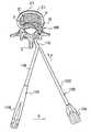
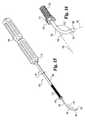
- FIG. 7is a perspective view of a distractor according to the present invention.
- FIG. 8is a perspective view of an alternative distractor having application in the present invention.
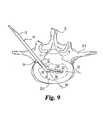
- FIG. 9is a top plan view of a vertebra with the distractor of FIG. 7 inserted in the disc space.
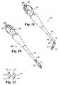
- FIG. 10is a perspective view of a straight reamer according to the present invention having the outer shaft partially cut-away to show the inner shaft.
- FIG. 11is a perspective view of a curved reamer according to the present invention having the outer shaft partially cut-away to show the inner shaft.
- FIG. 12is an end view of the reamer cutting head used with the reamers of FIGS. 10 and
- FIG. 13is a top plan view of a vertebra with the straight reamer of FIG. 10 inserted in the disc space.
- FIG. 14is a top plan view of a vertebra with the curved reamer of FIG. 11 inserted in the disc space.
- FIG. 15is a perspective view of a guided rotary cutter according to the present invention.
- FIG. 16is an enlarged view of the distal end portion of the cutter of FIG. 15 .
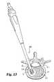
- FIG. 17is a top plan view of a vertebra with the cutter of FIG. 15 inserted in the disc space.
- FIG. 18is a perspective view of a guided rotary cutting tool according to the present invention.
- FIG. 19is an enlarged perspective view of the distal end portion of the cutting tool of FIG. 18 .
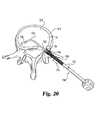
- FIG. 20is a top plan view of a vertebra with the cutting tool of FIG. 18 in the disc space.
- FIG. 21is a perspective view of an alternative cutting tool head.
- FIG. 22is a further perspective view of the cutting tool head of FIG. 21 .
- FIG. 23is a perspective view of a push scraper according to the present invention.
- FIG. 23 ( a )is section view taken through line 23 ( a )— 23 ( a ) of FIG. 23 .
- FIG. 24is a perspective view of a pull scraper according to the present invention.
- FIG. 24 ( a )is section view taken through line 24 ( a )— 24 ( a ) of FIG. 24 .
- FIG. 25is a top plan view of a vertebra with the push scraper of FIG. 23 .
- FIG. 26is a top plan view of a vertebra with the pull scraper of FIG. 24 .
- FIG. 27is a perspective view of a straight chisel according to the present invention.
- FIG. 28is a lateral elevational view of a spinal column segment with the chisel of FIG. 27 inserted in the disc space.
- FIG. 29is a posterior elevational view of a spinal column segment showing the disc space entrance created by the chisel of FIG. 27 .
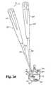
- FIG. 30is a perspective view of an alternate embodiment guided chisel according to the present invention.
- FIG. 31is an enlarged perspective view of the chisel head and shaft with the chisel head in the position of FIG. 30 .
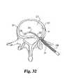
- FIG. 32is a top plan view of a vertebra with the chisel of FIG. 30 .
- FIG. 33is a perspective view an implant sizing guide according to one aspect of the present invention.
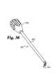
- FIG. 34is the implant sizing guide of FIG. 33 with the handle detached.
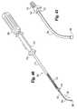
- FIG. 35shows a perspective view of an implant insertion guide according to the present invention.
- FIG. 35 ( a )is an enlarged view of the distal end portion of the implant insertion guide of FIG. 35 .
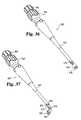
- FIG. 36is a perspective view of a straight implant inserter according to the present invention having the outer shaft partially cut-away to show the inner shaft.
- FIG. 37is a perspective view of a curved implant inserter according to the present invention having the outer shaft partially cut-away to show the inner shaft.
- FIG. 38is a perspective view of an impaction tool according to the present invention.
- FIG. 39is a top plan view of the disc space showing the sequence of the curved inserter of FIG. 37 inserting an implant into the disc space.
- FIG. 40is a perspective view of an alternate embodiment guided implant inserter according to the present invention.
- FIG. 41is an enlarged perspective view of the distal portion of the implant inserter of FIG. 40 .
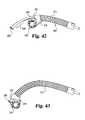
- FIG. 42is an enlarged plan view of the distal portion of the implant inserter of FIG. 40 and an implant.
- FIG. 43is the view of FIG. 42 showing the implant and insertion tool moved distally along the guide shaft.
- FIG. 44is a top plan view of a vertebra with the implant inserter of FIG. 40 in the disc space.
- FIG. 45is a top plan view of a vertebra with an implant inserted into the distal portion of the disc space.
- FIG. 46is a top plan view of a vertebra with a pair of implants bi-laterally positioned in the disc space to provide bi-lateral support to the spinal column segment.
- FIG. 47is a top plan view of a vertebra with a single implant positioned in the disc space to provide bi-lateral support to the spinal column segment.
- FIG. 48is a perspective view of an alternate embodiment implant inserter.
- FIG. 49is a perspective view of a still a further embodiment of an implant inserter.
- FIG. 50is a top plan view of an implant and instrument set for inserting the implant into the disc space.
- FIG. 51is a top plan view of the implant and instrument set of FIG. 50 with the implant partially inserted in the disc space.
- FIG. 52is an end elevational view of an implant according to another aspect of the present invention.
- FIG. 53is a top plan view of the implant of FIG. 52 .
- FIG. 54is a perspective of the implant of FIG. 52 oriented towards the posterior face.
- FIG. 55is another perspective view of the implant of FIG. 52 oriented towards the anterior face.
- FIG. 56is an elevational view of the implant of FIG. 52 looking towards the posterior face.
- the instruments and techniques of the present inventionprovide for improved unilateral disc space preparation in both the distal and proximal portions of the disc space through a single opening.
- Another difficulty in posterior lateral approaches to the disc spaceis related to the proper positioning of the implant in the portion of the disc space most distal from the posterior lateral opening. While it is desirable that the implant be positioned in the distal portion of the disc space, it is often too difficult to move the implant across the disc space to the distal portion.
- the present inventionfurther provides implant inserters, implant templates, implant insertion guides, and implants that facilitate implant positioning in the distal and proximal portions of the disc from a posterior lateral approach.
- Lamina spreader 500includes a first arm 502 pivotally joined to a second arm 504 by pin 506 . Arms 502 , 504 extend generally along a central axis 501 when in a first spreading position. Extending distally from pin 506 are distal portions 515 and 516 of arms 502 and 504 , respectively. Distal portions 515 and 516 include lamina engaging portions 508 and 510 , respectively.
- Lamina engaging portions 508 and 510are generally U-shaped and configured to engage the lamina of an upper vertebra V 2 and the lamina of a lower vertebra V 1 , respectively, on either side of the subject disc space, as shown in FIG. 3 .
- Spreading portion 508includes an outer portion 508 a configured to reside on the outer side of the lamina connected to an inner portion 508 b configured to reside on the inner side of the lamina.
- Spreading portion 510similarly includes an outer portion 510 a configured to reside on the outer side of the lamina connected to an inner portion 510 b configured to reside on the inner side of the lamina.
- the laminacan be spread by the surgeon grasping handle 502 a of arm 502 and handle 504 a of arm 504 , and forcing arms 502 , 504 towards one another in the direction towards axis 501 .
- the spreading mechanismincludes an externally threaded rod 512 threadingly engaged to branch 502 and a hand nut 514 received on rod 512 .
- Arms 502 and 504may be forced together by action of threading nut 514 to force rod 512 into threaded opening 503 in arm 502 , thereby forcing spreading portions 508 and 510 apart and separating the lamina to open access to the disc space.
- Nut 514can also be used to thread rod 512 into opening 503 after manually spreading the lamina via handles 502 a , 504 a , until nut 514 contacts arm 504 to maintain the engaging portions 508 , 510 in a spread condition.
- arm 502has handle portion 502 a that is hinged to rotate with respect to a non-rotating portion 502 b about a pin 516
- arm 504has handle portion 504 a hinged to rotate with respect to a non-rotating portion 504 b about a pin 518
- a first spring loaded locking mechanism 520resides in cut-out 524 formed in handle portion 502 a
- a second spring loaded locking mechanism 522resides in a similar cut-out (not shown) formed in handle portion 504 a
- Locking mechanism 520includes a finger 528 spring-biased into notch 530 formed in non-rotating portion 502 b .
- locking mechanism 522includes a finger spring-biased into a notch formed in non-rotating portion 504 b .
- the surgeon or attendantcan release handle portion 504 a by pulling proximally on grasping portion 534 to pull the finger out of the notch, and then rotate handle portion 504 a transversely to axis 501 about pin 518 to a position oriented about 90 degrees with respect to non-rotating portion 504 b .
- Rotating handle portions 502 a , 504 amoves this portion of lamina spreader out of the way of the surgeon and avoids interference with other instruments to be inserted in the disc space.
- spreader 500can be used to assist the surgeon in gaining access to the disc space.
- the rotating handlesallow lamina spreader 500 to remain in place during subsequent procedures. It is further contemplated that the surgeon may not desire to use lamina spreader 500 , and therefore proceed with disc space distraction after gaining access to the disc space.
- Disc space spreader 70has a proximal portion that includes a first branch 72 pivotally joined to a second branch 74 by pin 76 . Extending distally from pin 76 are distal portions 85 and 86 of branches 72 and 74 , respectively. Distal portions 85 and 86 have a distal working end that includes spreading portions 80 and 78 that contact the endplates of the adjacent vertebrae to apply a distraction force thereto. Distal portions 85 and 86 further include lateral offset portions 81 and 79 , respectively, that laterally offset the arms 72 , 74 from the spreading portions 80 , 78 .
- Offset portions 79 and 81have a straight portion extending generally parallel to axis 88 and a bend forming a first offset angle A 2 with axis 88 .
- Spreading portions 78 and 80form a second overall offset angle A 22 with axis 88 .
- offset angle A 2is about 120 degrees, but it is contemplated that offset angle A 2 can range from 90 degrees to 160 degrees.
- Offset angle A 22is about 110 degrees.
- the offset portions 79 , 81laterally offset branches 72 , 74 from spreading portions 78 , 80 , allowing arms 72 , 74 to be further pivoted across the spinous process S, as shown by disc space spreader 70 in FIG. 6, than would be possible without offset portions 79 , 81 .
- the lateral offset distance d between axis 88 and the center of the straight portionis between 10 to 20 millimeters. This allows the distal tip of spreader 70 to be properly oriented into posterior lateral opening 35 formed in disc space D 1 .
- disc space spreader 70includes a mechanism to force and/or maintain the separation of spreading portions 78 and 80 .
- the spreading mechanismincludes an externally threaded rod 82 pivotally joined to branch 72 and positionable in notch 83 formed in the proximal end of branch 74 .
- the spreading mechanismhas an internally threaded hand nut 84 threadedly received on rod 82 .
- Branches 72 and 74may be forced together by action of internally threaded nut 84 on branch 74 forcing it towards branch 72 , thereby forcing spreading portions 78 and 80 apart.
- Branches 72 and 74also define opposing grooves 92 and 94 adjacent pin 76 .
- a lever arm or pusher 90may be provided having an elongated shaft 96 with a handle 98 on one end and an opposing spreader engaging portion 99 .
- Engaging portion 99is configured for removable engagement with opposing grooves 92 and 94 formed in branches 72 and 74 , respectively.
- removal of bony structures to gain access to the disc space and resection of disc materialmay be conducted by known methods.
- the distal end of spreader 70is positioned at opening 35 , and pusher 90 can be used to provide a pushing force in the direction of arrow P into the disc space during the steps of inserting the spreading portions 78 and 80 into opening 35 .
- Disc space spreader 70is pivoted sequentially in the direction of arrow R about spinous process S via the proximal end of branches 72 , 74 .
- This pivotal and distal movement from proximal portion 41 to distal portion 37 of disc space D 1is indicated by the relative sequential positions of spreader 70 , 70 ′, 70 ′′, and 70 ′′′ and spreader portions 78 , 78 ′, 78 ′′, and 78 ′′′.
- branches 72 , 74 and pusher 90enable the surgeon to have simultaneous two-handed control of spreader 70 , with one hand controlling insertion movement with pusher 90 and the other hand controlling pivotal movement with arms 72 , 74 .
- the location of spreading portions 78 , 80 in the disc spacemay be checked by any known visualization techniques before proceeding to tissue removal.
- pusher 90is engaged to disc space spreader 70 during the steps indicated by spreaders 70 ′, 70 ′′ and 70 ′′′, but is not shown for purposes of clarity.
- the S-shaped connecting portions 79 , 81provide a lateral offset to branches 72 , 74 to laterally offset branches 72 , 74 from spreader portions 78 , 80 .
- Thisallows branches 72 , 74 of disc space spreader 70 to avoid interference with the spinous process S when inserting the distal portions spreader portions 78 , 80 through opening 35 into disc space D 1 .
- Enlarged stopscan be formed on distal portions 85 and 86 in order to engage the adjacent vertebra during insertion and limit advancement of spreaders 78 and 80 into disc space D 1 . After the spreader is inserted into the disc space, lever arm 90 may be removed.
- Disc space spreader 70is manipulated as described above to spread or distract disc space D 1 to the desired height.
- lamina spreader 500is first used to spread the lamina. Since this tends to tilt the disc space and make the vertebral endplates non-parallel, spreader 70 can then be used to distract the distal portion of the disc space to provided parallel endplates. Disc space spreader 70 can remain in the disc space during subsequent procedures.
- lamina spreader 500pedicle screw fixation with rods or plates on the other side of spinous process S may be used to maintain the distracted disc space height so that disc space spreader 70 can be removed.
- Distraction shimsmay also be used to maintain disc space distraction, such as disclosed in co-pending application entitled METHODS AND INSTRUMENTATION FOR DISTRACTION OF A DISC SPACE, filed Oct. 20, 1999, U.S. patent application Ser. No. 09/421,709, which application is incorporated herein by reference in it entirety.
- lamina spreader 500is not used by the surgeon, and the surgeon only uses disc space spreader 70 to restore the normal disc space height.
- Distractor 10includes an elongated shaft 12 having a longitudinal axis 34 .
- distractor 10includes a tool coupling 14 having a pair of opposed driving surfaces 16 and 18 .
- distractor 10includes a distraction head 20 with a straight section 31 joined to shaft 12 by bend 32 .
- Straight section 31has a longitudinal axis 29 disposed at an angle A 1 with respect to longitudinal axis 34 .
- angle A 1is between 120 and 160 degrees.
- Distraction head 20is joined to straight section 31 and has a longitudinal axis 33 at an angle A 11 with respect to axis 29 .
- angle A 11is between 20 and 60 degrees.
- Distraction head 20includes a pair of opposed distraction flats 26 and 28 separated by a first height.
- a second pair of opposed flats 22 and 24is separated by a second height, the second height being greater than the first height.
- distractor 50may include a lever arm 62 to assist in rotation of the distractor head after insertion into the disc space.
- Distractor 50includes a shaft 52 having a handle 54 opposite distractor head 56 .
- distractor head 56is joined to shaft 50 a lateral offset that includes a bend 58 and a straight section 59 .
- shaft 53includes multiple holes 60 , which preferably include an internal thread.
- Lever arm 62has a connection end 66 adapted to be removably received in a selected one of the holes 60 .
- Handle 64tends to allow the surgeon to generate a substantial torque on head 56 to rotate head 56 in the disc space.
- distractor 10may be utilized to distract adjacent vertebrae.
- Distractor head 20may be inserted into disc space D 1 through opening 35 .
- Distractor head 20may be inserted into the disc space D 1 until the distal tip is positioned adjacent the distal portion 37 and straight section 31 is disposed in disc space D 1 adjacent proximal portion 41 .
- Distractor 10is oriented during insertion in a reduced height configuration such that surface 26 of head 20 engages the endplate of vertebra V 1 .
- surface 28engages upper adjacent vertebra V 2 .
- distractor head 20creates a distraction height approximating the distance between surfaces 26 and 28 .
- Distractor shaft 12is then moved to cause rotation about axis 33 of the distraction head 20 bringing surfaces 22 and 24 into contact with the opposing endplate surfaces, thereby distracting the disc space to the second, greater height between surfaces 22 , 24 .
- Lamina spreader 500pedicle screw fixation with rods or plates may be used to maintain disc space height.
- Distraction shimsmay also be used to maintain disc space distraction.
- FIG. 10A straight reamer is illustrated in FIG. 10 and a curved reamer is illustrated in FIG. 11 .
- Straight reamer 200includes a hollow outer shaft 202 with a handle 204 attached to the proximal portion thereof.
- a rotatable inner shaft 206is disposed within outer shaft 202 .
- Rotary cutting head 210 having a cavity 213is coupled to inner shaft 206 .
- a Hudson type tool coupler 208is provided at the proximal portion of inner shaft 206 . It will be understood that a manual handle, such as a T-handle, may be attached to tool coupler 208 .
- Cutting head 210 of curved reamer 200may be moved to various locations in the proximal portion 41 of disc space D 1 and the cutting head reinserted to widen or alter a previously formed channel.
- a powered rotary drivermay also be coupled to tool coupler 208 to mechanically drive inner shaft 206 and rotate cutting head 210 .
- curved reamer 220includes a hollow outer shaft 222 with a handle 224 attached to the proximal portion thereof.
- a rotatable inner shaft 226is disposed within outer shaft 222 .
- Rotary cutting head 210(identical to the head provided on reamer 200 ) having a cavity 213 is coupled to inner shaft 206 .
- Outer shaft 222includes a bend 221 angled at offset angle A 3 of preferably about 110 degrees, permitting insertion of cutting head 210 through opening 35 and into distal portion 37 of disc space D 1 , as shown in FIG. 14 . It is further contemplated that A 3 may range from 100 to 150 degrees. Further, while a fixed bend is shown for the purpose of illustration in FIG.
- outer shaft 222may include a flexible portion or mechanical coupling permitting a plurality of angles for bend 221 .
- Inner shaft 226is preferably flexible at least through bend 221 so that rotary torque can be transmitted through bend 221 .
- the flexible inner shafts used with the instruments of the present inventioncan be made from, for example, stainless steel coiled wire or nitinol.
- a Hudson type tool coupler 228is provided at the proximal portion of inner shaft 226 .
- a manual handlesuch as a T-handle
- a powered rotary drivermay be coupled to tool coupler 228 to mechanically drive inner shaft 226 and rotate cutting head 210 .
- cutting head 210 of curved reamer 220may be moved to various locations in the distal portion 37 of disc space D 1 and the cutting head reinserted to widen or alter a previously formed channel.
- straight reamer 200 and curved reamer 220allow the surgeon to remove disc material, cartilage and other tissue in both proximal portion 41 and distal portion 37 of disc space D 1 through opening 35 .
- cutting head 210includes cutting edges 211 a , 211 b , 211 c , and 211 d .
- Cutting head 210has a smooth, non-cutting profile between edges 211 a , 211 d and between edges 211 b , 211 c . It is contemplated that head 210 is inserted with the non-cutting profiles oriented towards the vertebral endplates to provide smooth insertion and positioning of cutting head 210 in the disc space. The location of cutting head 210 in the disc space may be checked by any known visualization techniques before proceeding to tissue removal.
- edges 211 a and 211 ccut tissue and cartilage, while edges 211 b and 211 d pass over the tissue without cutting.
- the cut materialis deposited in cavity 213 , where it may then be extracted from the disc space.
- Cutting head 210provides a safe and efficient discectomy tool that preserves the bony endplate surface and quickly collects the soft tissue.
- Cutter 100includes a guiding shaft 102 having an interconnected handle 109 disposed on the proximal end and a stop 106 disposed on the opposing distal end. Stop 106 may be substantially radiopaque to provide an indication of inner shaft location on x-ray images.
- Distal portion 103is joined to shaft 102 by bend 104 .
- Bend 104is preferably a substantially uniform curve creating angle A 3 between axis 105 of shaft 102 and axis 107 of distal portion 103 .
- Outer shaft 108Disposed on guide shaft 102 between handle 109 and stop 106 is an outer shaft 108 .
- Outer shaft 108includes a handle 110 on a proximal end and a flexible drive 112 on the opposing distal end.
- a cutting head 114is interconnected with flexible drive 112 .
- cutting headincludes a number of cutting blades configured for rotary cutting.
- Flexible drive 112is designed to transmit both longitudinal force to advance cutting head along guiding shaft 102 in the direction arrow 116 and also transmit rotation force in the direction of arrow 118 to move cutting head 114 in a circular manner about shaft 102 , thereby engaging cutting blades 120 with adjacent tissues. While other flexible drives, such as, for example but without limitation, cables and mechanical couplings may be utilized, in a preferred embodiment flexible drive 112 is a helically wound cable.
- cutter 100may be inserted into disc space D 1 through opening 35 .
- stop 106is positioned adjacent distal disc space portion 37 and bend 104 may be positioned centrally in the disc space.
- the location of guide shaft 102 in the disc spacemay be checked by any known visualization techniques before proceeding to tissue removal.
- forceis applied to handle 110 to advance cutting head 114 into contact with structures adjacent the disc space.
- Forward pressure in the direction of arrow 116may be maintained as rotational force in the direction of arrow 118 is transmitted to cutting head 114 .
- tissueis removed cutting head 114 may cuttingly advance along guide shaft 102 until it reaches stop 106 .
- Cutting head 114has an internal channel (not shown) sized to receive shaft 102 but limited in size and shape such that the cutting head may not extend beyond stop 106 .
- cutting tool 100forms an arcuate channel through the disc space by following guiding shaft 102 .
- Guide shaft 102may be moved to one or more new locations in the disc space and the cutting head reinserted to widen or alter a previously formed channel in disc space D 1 .
- Shaver 150includes a guide rod 152 with a handle 158 disposed at the proximal end and a stop 156 disposed on the distal end.
- Guide rod 152includes bend 154 adjacent the distal end.
- Outer shaft 160is slidably mounted on guide rod 152 .
- Outer shaft 160includes a handle 162 on its proximal end and is coupled to flexible drive 164 on its distal end.
- a shaving head 166is mounted on flexible drive 164 .
- shaving head 166has a plurality of cutting blades adapted to shave tissue as the head is rotated.
- individual blades of head 166are elongated and include a forward cutting blade 168 and backward cutting blade 170 and a cavity 169 for deposit of material. Still more preferably, shaving head 166 has sufficiently flexibility to allow it to conform at least partially to bend 154 as it is advanced along guide rod 152 towards stop 156 .
- shaver 150may be positioned in disc space D 1 with stop 156 disposed adjacent distal disc space portion 37 as shown in FIG. 20 .
- shaver 150will follow use of cutter 100 to further define and expand the arcuate channel defined in the disc space.
- handle 162may be rotated thereby rotating head 166 in the direction of arrow 173 to cut tissue, and cut tissue can be accumulated between the blades and in cavities 169 for removal from disc space D 1 .
- Shaver head 166preferably cuts in both directions, however it is also contemplated that the shaver may be unidirectional.
- Shaver head 180is slidably disposed on inner shaft 182 and may be advanced along the shaft until it reaches stop 186 .
- Shaver head 180includes a flexible drive portion 190 and a helical cutting blade 188 disposed on the distal portion of the flexible drive.
- flexible drive 190rotates
- helical blade 188cuts the tissue and accumulates tissue between the blades for removal from the disc space.
- Push scraper 260includes an elongated shaft 262 with a handle 264 on the proximal end and a push scraper head 265 on the distal end.
- Scraper head 265is joined to and is substantially perpendicular to shaft 262 .
- scraper head 265includes distally facing upper and lower cutting blades 266 having a distal concave face 267 with a hole 268 formed therein. Concave face 267 forms a trough around hole 268 .
- the proximal face 269 of scraper head 265has a smooth, convex non-cutting profile to facilitate proximal movement of scraper head 265 through the disc space.
- push scraper 260is inserted through opening 35 with scraper head 265 initially positioned towards proximal portion 41 of disc space D 1 .
- Push scraper 260is then pivoted and pushed distally through disc space D 1 , as indicated by push scraper 260 ′, to position scraper head 265 ′ towards distal portion 37 of disc space D 1 .
- Distally facing blades 266remove disc material and can deposit at least some of the material in the trough between blades 266 during this distal pivotal movement for subsequent removal.
- a pusher as described hereincan be used to facilitate this distal pivotal movement.
- a pull scraper 270includes an elongated shaft 272 with a handle 274 on the proximal end and a pull scraper head 275 on the distal end.
- Scraper head 275is joined to and extends substantially perpendicular to shaft 272 .
- Scraper head 275includes proximally facing cutting blades 276 and a concave proximal face 277 with a hole 278 formed therein. Concave face 277 forms a trough around hole 278 .
- the distal face 279 of scraper head 275has a smooth, convex non-cutting profile to facilitate distal movement of scraper head 275 through the disc space. As shown in FIG.
- pull scraper 270is inserted through opening 35 and scraper head 275 is pushed through disc space D 1 to initially position scraper head 275 towards distal portion 37 of disc space D 1 .
- Pull scraper 270is then pivoted and pulled proximally through disc space D 1 , as indicated by pull scraper 270 ′, to position scraper head 275 ′ towards proximal portion 41 of disc space D 1 .
- Proximally facing blades 276remove any remaining disc material and can deposit at least some of the material in the trough between blades 276 during this proximal pivotal movement for subsequent extraction.
- Chisel 540When the desired amount material has been removed from disc space D 1 using the instruments described above, a straight chisel 540 as shown in FIG. 27 is provided for preparing a square entrance port into disc space D 1 for implant insertion.
- Chisel 540includes shaft 542 having a handle 544 coupled to the proximal end of shaft 542 .
- a chisel head 546is provided at the distal end of shaft 542 .
- Chisel head 546includes a body portion 547 having a pair of non-cutting extensions 548 extending distally therefrom. Extensions 548 have an upper surface 548 a for contacting vertebra V 2 and a lower surface 548 b for contacting lower vertebra V 1 .
- Extensions 548guide chisel head 546 into the disc space, ensuring equal amounts of material are removed from the endplates of the upper and lower vertebrae by upper cutting edge 550 and lower cutting edge 551 .
- V-shaped portions 552 , 553distally offset edges 550 , 551 , respectively, with respect to body portion 547 .
- a chamber 554is formed in body portion 547 , and body portion 547 has upper and lower openings positioned proximally of the upper and lower cutting edges 550 , 551 . Cut material can be deposited through these upper and lower openings and into chamber 554 .
- chisel 540is shown with extensions 548 in disc space D 1 .
- Chisel head 546is impacted into the disc space, with cutting edges 550 , 551 removing bone material and osteophytes from the vertebral endplates.
- Thisprovides, as shown in FIG. 29, an enlarged squared entrance to disc space D 1 is formed at the proximal portion of the disc space that is larger than the opening created by spreading the lamina and distracting disc space D 1 .
- This enlarged entrancefacilitates implant insertion into the disc space.
- the material removed to form the enlarged entranceis indicated by cut-away portions C in vertebra V 1 and V 2 .
- Chisel 230includes an inner shaft 232 with a handle 238 connected to the proximal end and a stop 236 formed on the distal end.
- inner shaft 232preferably has a non-circular cross section 233 adjacent the distal portion.
- the non-circular cross sectionpreferably square, inhibits rotation of the chisel cutting head as it is impacted along inner shaft 232 .
- Outer shaft 240is slidably disposed about inner shaft 232 .
- Outer shaft 240includes a drive region 242 with an impact shoulder 244 .
- Outer shaft 232is coupled to chisel head 248 by flexible drive 246 .
- Chisel head 248includes an upper cutting edge 254 and a lower cutting edge 252 .
- the cutting bladesare spaced by extensions 249 and 251 that control and limit the depth of penetration of the cutting edged into the endplates.
- inner shaft 234is positioned in disc space D 1 through opening 35 .
- Stop 236is position adjacent the distal portion 37 of disc space D 1 .
- Visualization of the placement of inner shaft 234may be made to confirm proper positioning.
- chisel head 248is advanced along inner shaft 232 in the direction of arrow 250 .
- a forked slap hammer or pushermay be positioned with the forks extending on either side of drive region 242 .
- the slap hammermay then be forcibly urged against impact shoulder 244 to drive chisel head 248 into the disc space.
- the chisel headis advanced until it engages stop 236 . This action forms a substantially square or rectangular arcuate channel extending into each of the adjacent vertebral endplates.
- Template inserter 560includes a shaft 562 having a handle 564 detachably secured to the proximal end of shaft 562 .
- a bend 566is secured to the distal end of shaft 562 and forms offset angle A 3 .
- a template 568is secured at the distal end of bend 566 .
- a notch 567is provided in shaft 562 that is engageable by a pusher, such as pusher 670 described below, to facilitate placement of template 568 into disc space D 1 .
- Template 568is positionable through opening 35 into the distal portion of disc space D 1 to determine if enough material has been removed from the disc space to accommodate the implant to be inserted therein, or to determine the size of implant required.
- Handle 564is removable for fluoroscopic or radiographic imaging of template 568 in disc space D 1 , allowing the surgeon to confirm the fit and positioning of template 568 in disc space D 1 .
- Templates 568 of various heights h 1 having various sized bends 566can be provided so the surgeon can perform multiple trials to obtain information as to the proper implant size.
- Insertion guide 600has a proximal portion that includes a first branch 602 pivotally joined to a second branch 604 by pin 606 . Extending distally from pin 606 are distal portions 615 and 616 of branches 602 and 604 , respectively. Distal portions 615 and 616 have a distal working end that includes guide members 608 and 610 extending from lateral offsets 609 and 611 , respectively.
- Offset portions 609 and 611have a straight portion extending generally parallel to and offset by distance d from axis 618 , and a bend forming a first offset angle A 2 with axis 618 .
- Guide members 608 and 610have an arcuate form extending from offset portions 609 , 611 to the distal tip insertion guide 600 . This shape generally corresponds to the shape of the implant insertion path P, as discussed below.
- Guide members 608 , 610preferably have a length and shape such that the distal tip of inserter guide 600 is positionable in the desired location in distal portion 37 of disc space D 1 .
- These offset portions 609 , 611laterally offset branches 602 , 604 from guide members 608 , 610 .
- Thisprovides room for placement of an implant insertion instrument, such as those described below, or the implant template inserter 560 described above, alongside branches 602 , 604 .
- the implantcan be slid along guide members 608 , 610 and into the disc space, and guide members 608 , 610 provide a barrier that protects the anterior portion of the disc space during implant insertion.
- branches 602 and 604 of inserter guide 600can be manipulated to separate guide portions 608 , 610 and place guide portions 608 , 610 in contact with the vertebral endplates. This contact allows the desired position of guide members 608 , 610 to be maintained during implant insertion. Further, such separation capabilities might be required in order to further distract disc space D 1 to facilitate implant insertion or removal.
- Inserter guide 600includes a mechanism to force and/or maintain the separation of guide members 608 and 610 .
- the spreading mechanismincludes an externally threaded rod 612 joined to branch 602 and extending through hole 613 formed in the proximal end of branch 604 .
- the spreading mechanismhas an internally threaded hand nut 614 threadedly received on rod 612 .
- Branches 602 and 604may be forced together by action of internally threaded nut 614 on branch 604 forcing it towards branch 602 , thereby forcing guide members 608 and 610 apart and into contact with the vertebral endplates.
- Inserter 630includes a rigid hollow outer shaft 632 secured to a handle 634 at the proximal end of shaft 632 .
- An inner shaft 636extends through outer shaft 632 and includes an implant connector 638 at its distal end extending distally from the distal end of outer shaft 632 .
- Implant connector 638is preferably threaded, but can include other attachment means for engaging the implant.
- Inner shaft hand nut 642is coupled to inner shaft 636 , and can be rotated to in turn rotate connector 638 to secure or release the implant thereto as desired.
- a bearing member 640is secured to outer shaft 636 , and contacts the wall of implant to direct an insertion force to the implant.
- Inserter 650includes a rigid hollow outer shaft 652 secured to a handle 654 at the proximal end of shaft 652 .
- Outer shaft 652includes a bend 655 adjacent its distal end forming offset angle A 3 .
- a flexible inner shaft 656extends through outer shaft 652 and bend 655 .
- Inner shaft 656includes an implant connector 658 at its distal end extending distally from the distal end of outer shaft 652 .
- Implant connector 658includes threads or other attachment means for engaging an implant.
- Inner shaft hand nut 662is coupled to inner shaft 656 , and can be rotated to in turn rotate connector 658 to secure or release the implant thereto as desired.
- a bearing member 660is secured to outer shaft 656 , and contacts the wall of the implant to direct the insertion force thereto.
- An impaction tool engaging portion 664 in the form of a notch formed around outer shaft 664is provided in outer shaft 652 .
- An impaction tool or pusher 670includes a shaft 672 having a bulb handle 674 secured to the proximal end of shaft 672 .
- a shaft engaging portion 674is secured to and extends from the distal end of shaft 672 .
- shaft engaging portion 674is a U-shaped prong, and is positionable in notch 664 to apply a pushing force to curved inserter 650 to facilitate placement the implant secured to inserter 650 into distal portion 37 of disc space D 1 .
- Insertion of implant I with curved inserter 650is shown in FIG. 39 .
- Implant Iis attached to inserter 650 , and implant I is then positioned in opening 35 with inserter 650 oriented such that it extends across spinous process S.
- inserter 650is pivoted around spinous process S to the position indicated by inserter 650 ′.
- Pusher 670can be used to facilitate insertion by allowing the surgeon to use pusher 670 to apply the insertion force with one hand while the other hand is used to pivot inserter 650 .
- FIGS. 40 through 44An alternate embodiment implant insertion device is shown in FIGS. 40 through 44.
- the implant inserter 300includes an inner guiding shaft 302 having a handle 308 attached to one end and a stop 306 disposed on the opposite end. Guiding shaft 302 includes a bend 304 adjacent the distal portion. Insertion sleeve 310 is slidably disposed about inner shaft 302 . As previously described with respect to chisel 230 , insertion sleeve 310 includes a drive portion 314 and impact shoulder 316 for use with a slap hammer, if necessary. Insertion sleeve 310 is connected at its distal end to an implant driver 318 by a flexible drive member 312 . Implant driver 318 includes an arcuate cavity 322 having a substantially concave surface. The concave surface terminates adjacent the inner shaft 302 .
- Implant 300is one example of an implant that may be inserted with instruments according to the present invention. Further suitable implants are disclosed in U.S. Pat. No. 5,897,556 and also in PCT International Application Ser. No. PCT/US00/41392 entitled IMPACTED ORTHOPEDIC BONE SUPPORT IMPLANT, filed Oct. 20, 2000, each of which is incorporated herein by reference in its entirety.
- the implant inserted with the instruments and techniques of the present inventioncould also be a spacer, a disc prosthesis or disc nucleus prosthesis.
- inner shaft 302 of implant inserteris positioned in disc space D 1 with stop 306 positioned adjacent distal portion 37 .
- Implant 330is positioned in opening 35 and implant driver 318 is urged forwardly along guide shaft 304 to drive the implant to distal portion 37 of disc space D 1 as shown in FIG. 45 .
- bone ingrowth promoting materialmay be positioned around implant 330 using guide rod 302 as a guide for placement. Bone ingrowth promoting material 331 can also be placed in the interior portions of implant 330 prior to placement. Additionally, bone ingrowth promoting material 342 may be positioned in the anterior portion 39 of the disc space.
- a second implant 349may be placed in the proximal portion 41 of the disc space to complete a bilateral placement of implants to provide balanced structural support in disc space D 1 . Second implant 349 may also be filled with bone growth promoting material 351 .
- a single guide rodmay be positioned in the disc space and multiple instruments advanced over the guide rod to complete disc space preparation and implant insertion.
- the stop on the guide rodmay include selectively engageable portions that may be engaged with the vertebral endplates to maintain the position of the guide rod in the disc space.
- the disc spaceis prepared using the any combination of instruments described above.
- the anterior portion 39 of the disc spacemay be packed with bone ingrowth promoting material 342 .
- a dual lobe implant 370which can have features such as those described below with respect to implant 1000 , is placed in the disc space D 1 and has a length sufficient to span the disc space from the distal portion 37 to the proximal portion 41 .
- Implant 370includes a first distal lobe 372 and a second proximal lobe 374 .
- a central opening 376is provided that may be filled with bone ingrowth material.
- Implant 370may be positioned by using any of the implant inserters described herein.
- FIG. 48illustrates one example another embodiment implant inserter according to the present invention.
- Implant inserter 400includes an elongated shaft 402 with a handle 404 at its proximal end and an implant-gripping end at the opposite end.
- the implant-gripping endincludes bifurcated branches 408 and 410 separated by a space 412 .
- the bifurcated brancheseach include a bend 406 to accommodate implant placement through opening 35 and into disc space D 1 .
- Branch 408includes an inclined surface 414 and an implant engagement block 418 .
- branch 410includes inclined surface 416 and an implant engagement block 420 .
- Each engagement blockincludes at least one projection (not shown) for insertion into a wall opening of implant 422 having a bearing surface to engage implant 422 .
- An outer sleeve 424is slidably disposed on inner shaft 402 with an internal channel 426 . It will be understood that as sleeve 424 is advanced toward implant 422 , sleeve 424 will engage inclines 414 and 416 thereby urging branches 408 and 410 towards each other. The projections on engagement blocks 418 and 420 will then firmly engage implant 422 .
- implant inserter 450has an implant engagement end 456 offset from shaft 452 by a bend 454 .
- a pusher 460includes a handle 464 at one end and a projection (not shown) at the opposite end 462 for engagement with a corresponding opening (not shown) on shaft 452 .
- Pusher 460provides a mechanism for the surgeon to use one hand to urge implant 458 across disc space D 1 , while the other hand of the surgeon pivots implant 458 with inserter 450 as it is moved across disc space D 1 .
- the longitudinal axis of pusher 460is in relatively substantial alignment with the longitudinal axis of implant engagement end 456 . Thus, longitudinal force applied on pusher 460 may be directly transmitted as longitudinal force to advance implant 458 into the disc space.
- the instrument setincludes an implant insertion tool in the form of inserter 1100 , an impaction tool in the form of pusher 1200 , and driver 1300 .
- Inserter 1100has a proximal portion with a shaft 1106 and a handle 1108 secured to the proximal end of shaft 1106 .
- Shaft 1106includes has a distal working end having a rotatable connecting portion 1102 with a threaded distal end portion 1104 for engaging a threaded opening on implant 1000 .
- a male protrusion member 1105extends from end portion 1104 , and is positionable in a slot formed in implant 1000 as described further below.
- Shaft 1106further includes a lateral offset 1110 having a bend forming angle A 2 with shaft 1106 , and a straight portion offset distance d from shaft 1106 . This allows shaft 1106 to be initially positioned across spinous process S, as shown in FIG., 51 , and then pivoted in the direction of arrow R away from spinous process S as implant 1000 is positioned in disc space D 1 .
- Pusher 1200has a shaft 1202 and handle 1204 at the proximal end of shaft 1202 .
- Pusher 1200further includes a reduced diameter distal end portion 1206 positionable in an impaction tool engaging portion in the form of bore 1112 formed in shaft 1106 .
- inserter 1200can be used to apply a pushing force to implant 1000 in the direction of arrow P while inserter 1100 is pivoted in the direction of arrow R to pivot the leading end of implant 1000 towards distal portion 37 of disc space D 1 . It should be understood that inserter 1100 does not pivot with respect to implant 1000 , but rather inserter 1100 follows the proximal end of implant 1000 as the distal end of implant 1000 is pivoted to move implant 1000 non-linearly into and across the disc space along insertion path P.
- the inserter 1100 and pusher 1200provide the surgeon the ability to use two-handed control to insert implant 1000 into the disc space along non-linear path P since the surgeon controls inserter 1100 with one hand while the other hand provides a pushing or impaction force on implant 1000 with pusher 1200 .
- Implant 1000is an interbody fusion device or cage that can be packed with bone growth material or other known substance and inserted into disc space D 1 to promote bony fusion between vertebrae V 1 and V 2 . Furthermore, the structural features of implant 1000 can have application for a disc prosthesis or a disc nucleus prosthesis that is to be inserted into disc space D 1 through opening 35 . Implant 1000 has a boomerang or banana shape that is suited for insertion to provide bi-lateral support in disc space D 1 through a unilateral approach, after the disc space D 1 has been accessed and prepared using the above described instruments and techniques.
- disc space D 1can be accessed and prepared for implant insertion using any other known techniques and instruments prior to inserting implant 1000 .
- a particular problemexists providing bilateral support to the intradiscal space in instances where the disc space is accessed from a posterior lateral approach, such as a transforaminal approach, due to the difficulty in accessing and inserting the implant into distal portion 37 of disc space D 1 .
- Implant 1000addresses this problem by providing a design that is suited for insertion into opening 35 and for subsequent pivotal movement and impaction movement through disc space D 1 into distal portion 37 .
- Implant 1000includes a concave posterior wall 1002 and an opposite convex anterior wall 1004 .
- Implant 1000further includes an arcuate leading end wall 1006 and an arcuate trailing end wall 1008 .
- Each of the end walls 1006 , 1008extend between and connect posterior wall 1002 and anterior wall 1004 , and provide a smooth transition therebetween to facilitate passage of implant 1000 through disc space D 1 .
- Implant 1000further includes an upper bearing member 1010 and a lower bearing member 1012 extending between and connecting walls 1002 , 1004 , 1006 and 1008 .
- Implant 1000has a height H 1 at the medial portion of posterior wall 1002 and a second height H 2 at the medial portion of anterior wall 1004 .
- Upper bearing member 1010 and lower bearing member 1012have a slight convexity between the anterior and posterior walls 1002 , 1004 and height H 2 is preferably greater then H 1 in order to correspond to the anatomy of the vertebral endplates at the posterior portion of disc space D 1 .
- Leading end wall 1006 and trailing end wall 108further have a height H 3 that is less than H 1 and H 2
- upper bearing member 1010 and lower bearing member 1012have a slight convexity between leading end 1006 and trailing end 1008 as best shown in FIG. 56 .
- This double convexitypreferably matches the double concavity of the adjacent vertebral endplate.
- Upper bearing member 1010can further be provided with a number of grooves 1014 and lower bearing member 1012 can be provided with a number of grooves 1016 .
- Grooves 1014 and 1016can engage the vertebral endplates to resist posterior and anterior migration of implant 1000 in the disc space.
- Upper bearing member 1010includes upper openings 1018 a and 1018 b separated by an upper strut 1019 .
- Lower bearing member 1012includes lower openings 1020 a and 1020 b separated by a lower strut 1021 .
- An upper bar 1022 forming the perimeter of upper bearing member 1010has a boomerang shape, and surrounds upper openings 1018 a , 1018 b and is connected to strut 1019 .
- a lower bar 1024 forming the perimeter of lower bearing member 1012has a boomerang shape, and surrounds lower openings 1020 a , 1020 b and is connected to strut 1021 .
- Posterior wall 1002includes a pair of posterior lateral openings 1026 a and 1026 b adjacent to the posterior side of leading end wall 1006 and trailing end wall 1008 , respectively.
- Posterior vertical struts 1030 a and 1030 bextend between and are connected to upper bar 1022 and lower bar 1024 on the medial side of openings 1026 a and 1026 b , respectively.
- a posterior middle opening 1028 that is larger than posterior lateral openings 1026 a , 1026 bis defined between vertical struts 1030 a , 1030 b.
- Anterior wall 1004includes a pair of anterior lateral openings 1032 b and 1032 a adjacent to the anterior side of leading end wall 1006 and trailing end wall 1008 , respectively.
- Anterior vertical struts 1034 a and 1034 bextend between and are connected to upper bar 1022 and lower bar 1024 on the medial side of openings 1032 a and 1032 b , respectively.
- An anterior middle opening 1036 that is larger than anterior lateral openings 1032 a , 1032 bis defined between vertical struts 1034 a , 1034 b .
- An offset strut 1038is provided at the middle of opening 1036 , and extends between and is connected with upper bar 1022 and lower bar 1024 .
- offset strut 1038is offset toward posterior wall 1002 , and offset strut 1038 is also connected with upper strut 1019 and lower strut 1021 .
- offset strut 1038 and middle opening 1036provide upper member 1010 with an upper cantilevered portion 1040 and lower member 1012 with a lower cantilevered portion 1042 .
- the cantilevered portions 1040 , 1042facilitate x-ray assessment of fusion in the middle of disc space D 1 since there is no structural member blocking an x-ray image taken from a lateral view.
- Implant 1000is also provided with an inserter engaging portion 1048 at trailing end 1008 and an identical inserter engaging portion 1044 at leading end 1006 so that implant 1000 is insertable into disc space D 1 from a unitalteral approach taken on either side of the spinous process.
- Inserter engaging portions 1044 , 1048are preferably internally threaded and engageable with a distal end of an implant inserter, such as threaded end portion 1104 of inserter 1100 described above.
- a slot 1046extends upwardly and downwardly from inserter engaging portion 1044 to upper bearing member 1010 and lower bearing member 1012 .
- a slot 1050extends upwardly and downwardly from inserter engaging portion 1048 to upper bearing member 1010 and lower bearing member 1012 .
- Slots 1046 , 1050receive male member 1105 of inserter 1100 to prevent rotation of implant 1000 with respect to inserter 1100 when implant 1000 is engaged thereto. The cooperation between slots 1046 , 1050 and male member 1105 also properly orients inserter 1100 with respect to implant 1000 when implant 1000 is engaged thereto.
- implant 1000has an axis C extending through its centroid.
- Axis Cextends generally in the direction between the leading end and the trailing end of implant 1000 , and is equal distance from the most posterior point A on leading end wall 1006 and the most posterior point B on trailing end wall 1008 .
- Leading end wall 1006is offset to the posterior side of axis C, and trailing end wall 1008 and engaging portions 1044 , 1048 are also offset to the posterior side of axis C.
- the offset in the leading end and trailing ends of implant 1000facilitates the controlled insertion of implant 1000 along curved insertion path P.
- Driver 1300is used to connect implant 1000 to connecting portion 1104 of inserter 1100 .
- Distal end portion 1206 of pusher 1200is positioned in bore 1112 in shaft 1106 .
- the leading end 1106 of implant 1100is placed at the opening 35 .
- a manual or mechanical impaction forceis applied to pusher 1200 to push implant 1000 a desired amount into proximal portion 41 of disc space D 1 .
- Inserter 1100is pivoted in the direction of arrow R, thereby pivoting leading end 1106 in the disc in the posterior direction.
- Pusher 1200pivoted along with inserter 1200 , is then used to apply a further impaction force to push implant 1000 further into the disc space.
- Implant 1000provides many further advantages.
- the shape and location of the bars, struts and wallspositions the load bearing members at the strong bony surfaces of the vertebral endplates to provide maximum load support capacity and avoid implant subsidence into the vertebral endplates.
- the double convexity of the upper and lower bearing members in combination with the boomerang shapeprovides an intimate fit in the disc space and a profile that matches the concavity of the endplates, providing implant stability and promoting fusion.
- the openings and hollow interiormaximize the volume available to receive bone growth material and also maximize the contact surface area between the bone growth material and the adjacent bony structure.
- Implant 1000can be made from titanium, surgical grade stainless steel, or other bio-compatible material using fabricating techniques known in the art.
- the implants, instruments and methodshave been disclosed with reference to use in substantially open surgical procedures. However, it is contemplated that the implants, instruments and methods may be utilized through guide sleeves or tubes to provided greater protection to adjacent tissues, to reduce the size of access incisions, to provide direct visualization of the surgical site, and/or to provide greater control of the method.
- the implants, instruments and methodsmay further be used in combination with disc space preparation and implant insertion through microscopic or endoscopic instruments that provide direct visualization of the surgical site, such as disclosed in U.S. patent application Ser. No. 09/692,932 entitled METHODS AND INSTRUMENTS FOR ENDOSCOPIC INTERBODY SURGICAL TECHNIQUES, filed Oct. 20, 2000 which is incorporated herein by reference in its entirety.
Landscapes
- Health & Medical Sciences (AREA)
- Life Sciences & Earth Sciences (AREA)
- Biomedical Technology (AREA)
- Engineering & Computer Science (AREA)
- Orthopedic Medicine & Surgery (AREA)
- Surgery (AREA)
- Veterinary Medicine (AREA)
- Heart & Thoracic Surgery (AREA)
- Animal Behavior & Ethology (AREA)
- General Health & Medical Sciences (AREA)
- Public Health (AREA)
- Oral & Maxillofacial Surgery (AREA)
- Neurology (AREA)
- Medical Informatics (AREA)
- Molecular Biology (AREA)
- Nuclear Medicine, Radiotherapy & Molecular Imaging (AREA)
- Dentistry (AREA)
- Transplantation (AREA)
- Cardiology (AREA)
- Vascular Medicine (AREA)
- Physical Education & Sports Medicine (AREA)
- Prostheses (AREA)
- Surgical Instruments (AREA)
Abstract
Description
The present application claims the benefit of the filing date of Provisional application Ser. No. 60/160,667, filed Oct. 21, 1999, entitled INSTRUMENTS AND METHODS FOR UNILATERAL DISC SPACE PREPARATION AND IMPLANT INSERTION. The referenced application is incorporated herein by reference in its entirety.
The present invention relates to techniques for use in interbody fusion procedures, instruments for performing such procedures, and implants insertable in the spinal disc space. More specifically, but not exclusively, the present invention relates to implants, methods and instruments for use in a posterior lateral approach to the disc space, such as a transforaminal approach.
Normally intervertebral discs, which are located between endplates of adjacent vertebrae, stabilize the spine and distribute forces between the vertebrae and cushion vertebral bodies. The spinal discs may be displaced or damaged due to trauma, disease or aging. A herniated or ruptured annulus fibrosis may result in nerve damage, pain, numbness, muscle weakness, and even paralysis. Furthermore, as a result of the normal aging processes, discs dehydrate and harden, thereby reducing the disc space height and producing instability of the spine and decreased mobility. Most typically surgical correction of a collapsed disc space includes a discectomy (surgical removal of a portion or the entire intervertebral disc). The discectomy is often followed by restoration of normal disc space height and bony fusion of the adjacent vertebrae to maintain the disc space height.
Access to a damaged disc space may be accomplished from several approaches to the spine. One approach is to gain access to the anterior portion of the spine through a patient's abdomen. However, extensive vessel retraction is often required and many vertebral levels are not readily accessible from this approach. A posterior approach may also be utilized. However, this typically requires that both sides of the disc space on either side of the spinal cord be surgically exposed. This may require a substantial incision or multiple access locations, as well as extensive retraction of the spinal cord. To alleviate problems associated with both anterior and posterior approaches to the spine, a posterior lateral approach, such as a transforaminal approach, to the disc space may be utilized. While it is desirable to place one or more implants in the disc space so that the load of the spinal column is evenly distributed, accurate placement of implants in the disc space from a single posterior lateral approach has heretofore been extremely difficult. Thus, this approach to the spine is seldom used in practice.
Therefore, there remains a need for improved instruments, implants and techniques for use in a posterior lateral approach to the disc space that allows unilateral disc space preparation and implant insertion to provide bilateral stability to the subject disc space.
The present invention provides implants, instruments and methods particularly adapted for unilateral disc space preparation and implant insertion from a posterior lateral approach to the disc space, such as is provided with a transforaminal approach.
In one aspect a lamina spreader is provided. The lamina spreader has arms pivotally connected with one another. The arms each include a lamina engaging portion at the distal end of the arm. In a preferred form, the arms are hinged so that the proximal ends of the arms can be rotated out of the operative field while the spreader is engaged to the lamina.
In another aspect, a disc space spreader is provided. The spreader has a pair of branches pivotally connected to one another. The branches have a spreading portion attached to the distal end of each arm. Each arm includes a lateral offset extending between the spreading portion and the articulating arm. A spreading mechanism is provided to assist in separating the spreading portions. In a further form, a pusher is provided to assist the surgeon in inserting the spreading portions into the disc space.
In further aspect of the invention, rotatable distractors are provided with distractor heads configured for insertion into the disc space via a unilateral approach. A lever arm can be secured to the distractor shaft to assist in rotation of the distractor.
In still a further aspect of the invention, cutting tools for unilateral disc space preparation are provided. Cutting instruments according to the present invention preferably have a longitudinal shaft with a cutting blade disposed at the distal end of the shaft. The cutting instruments include straight and curved reamers, cutting blades that are movable along or around a guide shaft, pull scrapers and push scrapers, straight chisels, and curved chisels movable along a guide shaft.
In yet another aspect, the present invention provides improved devices for implant insertion. An implant template is provided for the surgeon to determine the required implant size. Implant insertion devices according to the present invention comprise a shaft having a longitudinal axis and an implant connector at the distal end of the shaft. The shafts can be straight, curved, or flexible. In one form, the distal end of the shaft includes a bend for implant insertion to the distal portion of the disc space. In another form, the inserter shaft has a lateral offset. According to a further aspect of the invention, a pusher is provided and useable with the inserter to facilitate implant placement in the disc space.
In still a further aspect, the present invention provides methods for disc space preparation and implant insertion from a unilateral transforaminal approach to the spine. The method contemplates accessing the disc space and providing a posterior lateral opening into the disc space. The lamina can be spread to facilitate access. The disc space is then distracted with disc space spreaders. Cutting instruments are inserted through the opening to remove disc material and bony material from the endplates to prepared the disc space for implant insertion. The implant is then inserted through the opening and into the distal portion of the disc space. In one form, the unilateral approach utilizes at least two bilaterally positioned implants, with one of the implants in the distal portion of the disc space. In a second form, a single implant laterally spanning the disc space is positioned through the opening.
Further aspects, forms, embodiments, objects, features, benefits, aspects and advantages of the present invention shall become apparent from the detailed drawings and descriptions provided herein.
FIG. 1 is a perspective view of a lamina spreader according to the present invention.
FIG. 2 is a perspective view of the lamina spreader of FIG. 1 with the handle portions rotated to a folded position.
FIG. 3 is an elevational view of a spinal column segment showing the distal portion of the lamina spreader of FIG. 1 engaged to the lamina on either side of a disc space.
FIG. 4 is a perspective view of a disc space spreader according to the present invention.
FIGS.5(a) and5(b) are perspective views of the disc space spreader of FIG. 4 with a lever arm and a perspective view of the lever arm, respectively.
FIG. 6 shows the sequence of the insertion of the disc space spreader of FIG. 4 into a disc space.
FIG. 7 is a perspective view of a distractor according to the present invention.
FIG. 8 is a perspective view of an alternative distractor having application in the present invention.
FIG. 9 is a top plan view of a vertebra with the distractor of FIG. 7 inserted in the disc space.
FIG. 10 is a perspective view of a straight reamer according to the present invention having the outer shaft partially cut-away to show the inner shaft.
FIG. 11 is a perspective view of a curved reamer according to the present invention having the outer shaft partially cut-away to show the inner shaft.
FIG. 12 is an end view of the reamer cutting head used with the reamers of FIGS.10 and
FIG. 13 is a top plan view of a vertebra with the straight reamer of FIG. 10 inserted in the disc space.
FIG. 14 is a top plan view of a vertebra with the curved reamer of FIG. 11 inserted in the disc space.
FIG. 15 is a perspective view of a guided rotary cutter according to the present invention.
FIG. 16 is an enlarged view of the distal end portion of the cutter of FIG.15.
FIG. 17 is a top plan view of a vertebra with the cutter of FIG. 15 inserted in the disc space.
FIG. 18 is a perspective view of a guided rotary cutting tool according to the present invention.
FIG. 19 is an enlarged perspective view of the distal end portion of the cutting tool of FIG.18.
FIG. 20 is a top plan view of a vertebra with the cutting tool of FIG. 18 in the disc space.
FIG. 21 is a perspective view of an alternative cutting tool head.
FIG. 22 is a further perspective view of the cutting tool head of FIG.21.
FIG. 23 is a perspective view of a push scraper according to the present invention.
FIG.23(a) is section view taken through line23(a)—23(a) of FIG.23.
FIG. 24 is a perspective view of a pull scraper according to the present invention.
FIG.24(a) is section view taken through line24(a)—24(a) of FIG.24.
FIG. 25 is a top plan view of a vertebra with the push scraper of FIG.23.
FIG. 26 is a top plan view of a vertebra with the pull scraper of FIG.24.
FIG. 27 is a perspective view of a straight chisel according to the present invention.
FIG. 28 is a lateral elevational view of a spinal column segment with the chisel of FIG. 27 inserted in the disc space.
FIG. 29 is a posterior elevational view of a spinal column segment showing the disc space entrance created by the chisel of FIG.27.
FIG. 30 is a perspective view of an alternate embodiment guided chisel according to the present invention.
FIG. 31 is an enlarged perspective view of the chisel head and shaft with the chisel head in the position of FIG.30.
FIG. 32 is a top plan view of a vertebra with the chisel of FIG.30.
FIG. 33 is a perspective view an implant sizing guide according to one aspect of the present invention.
FIG. 34 is the implant sizing guide of FIG. 33 with the handle detached.
FIG. 35 shows a perspective view of an implant insertion guide according to the present invention.
FIG.35(a) is an enlarged view of the distal end portion of the implant insertion guide of FIG.35.
FIG. 36 is a perspective view of a straight implant inserter according to the present invention having the outer shaft partially cut-away to show the inner shaft.
FIG. 37 is a perspective view of a curved implant inserter according to the present invention having the outer shaft partially cut-away to show the inner shaft.
FIG. 38 is a perspective view of an impaction tool according to the present invention.
FIG. 39 is a top plan view of the disc space showing the sequence of the curved inserter of FIG. 37 inserting an implant into the disc space.
FIG. 40 is a perspective view of an alternate embodiment guided implant inserter according to the present invention.
FIG. 41 is an enlarged perspective view of the distal portion of the implant inserter of FIG.40.
FIG. 42 is an enlarged plan view of the distal portion of the implant inserter of FIG.40 and an implant.
FIG. 43 is the view of FIG. 42 showing the implant and insertion tool moved distally along the guide shaft.
FIG. 44 is a top plan view of a vertebra with the implant inserter of FIG. 40 in the disc space.
FIG. 45 is a top plan view of a vertebra with an implant inserted into the distal portion of the disc space.
FIG. 46 is a top plan view of a vertebra with a pair of implants bi-laterally positioned in the disc space to provide bi-lateral support to the spinal column segment.
FIG. 47 is a top plan view of a vertebra with a single implant positioned in the disc space to provide bi-lateral support to the spinal column segment.
FIG. 48 is a perspective view of an alternate embodiment implant inserter.
FIG. 49 is a perspective view of a still a further embodiment of an implant inserter.
FIG. 50 is a top plan view of an implant and instrument set for inserting the implant into the disc space.
FIG. 51 is a top plan view of the implant and instrument set of FIG. 50 with the implant partially inserted in the disc space.
FIG. 52 is an end elevational view of an implant according to another aspect of the present invention.
FIG. 53 is a top plan view of the implant of FIG.52.
FIG. 54 is a perspective of the implant of FIG. 52 oriented towards the posterior face.
FIG. 55 is another perspective view of the implant of FIG. 52 oriented towards the anterior face.
FIG. 56 is an elevational view of the implant of FIG. 52 looking towards the posterior face.
For the purposes of promoting an understanding of the principles of the present invention, reference will now be made to the embodiments illustrated in the drawings, and specific language will be used to describe the same. It will nevertheless be understood that no limitation of the scope of the invention is intended thereby. Any alterations and further modification in the described processes, systems, or devices, and any further applications of the principles of the invention as described herein are contemplated as would normally occur to one skilled in the art to which the invention relates.
In a posterior lateral approach to the disc space, such as is provided with a transforaminal approach, it is often difficult to prepare the proper locations in the disc space to receive an implant. The instruments and techniques of the present invention provide for improved unilateral disc space preparation in both the distal and proximal portions of the disc space through a single opening. Another difficulty in posterior lateral approaches to the disc space is related to the proper positioning of the implant in the portion of the disc space most distal from the posterior lateral opening. While it is desirable that the implant be positioned in the distal portion of the disc space, it is often too difficult to move the implant across the disc space to the distal portion. Thus, the present invention further provides implant inserters, implant templates, implant insertion guides, and implants that facilitate implant positioning in the distal and proximal portions of the disc from a posterior lateral approach.
Referring now to FIG. 1, there is provided alamina spreader 500 according to one aspect of the present invention.Lamina spreader 500 includes afirst arm 502 pivotally joined to asecond arm 504 bypin 506.Arms central axis 501 when in a first spreading position. Extending distally frompin 506 aredistal portions arms Distal portions lamina engaging portions Lamina engaging portions portion 508 includes anouter portion 508aconfigured to reside on the outer side of the lamina connected to aninner portion 508bconfigured to reside on the inner side of the lamina. Spreadingportion 510 similarly includes anouter portion 510aconfigured to reside on the outer side of the lamina connected to aninner portion 510bconfigured to reside on the inner side of the lamina.
The lamina can be spread by thesurgeon grasping handle 502aofarm 502 and handle504aofarm 504, and forcingarms axis 501. There is also provided a mechanism to force and/or maintain spreadingportions rod 512 threadingly engaged tobranch 502 and ahand nut 514 received onrod 512.Arms nut 514 to forcerod 512 into threadedopening 503 inarm 502, thereby forcing spreadingportions Nut 514 can also be used tothread rod 512 intoopening 503 after manually spreading the lamina viahandles nut 514 contacts arm504 to maintain the engagingportions
In a preferred form,arm 502 hashandle portion 502athat is hinged to rotate with respect to anon-rotating portion 502babout apin 516, andarm 504 hashandle portion 504ahinged to rotate with respect to anon-rotating portion 504babout apin 518. A first spring loadedlocking mechanism 520 resides in cut-out524 formed inhandle portion 502a, and a second spring loadedlocking mechanism 522 resides in a similar cut-out (not shown) formed inhandle portion 504a.Locking mechanism 520 includes afinger 528 spring-biased intonotch 530 formed innon-rotating portion 502b. The surgeon or attendant can release handleportion 502aby pulling proximally on graspingportion 532 to pullfinger 528 out ofnotch 530, and then rotatehandle portion 502atransversely toaxis 501 aboutpin 516 to a position oriented about 90 degrees with respect tonon-rotating portion 502b. Similarly,locking mechanism 522 includes a finger spring-biased into a notch formed innon-rotating portion 504b. The surgeon or attendant can release handleportion 504aby pulling proximally on graspingportion 534 to pull the finger out of the notch, and then rotatehandle portion 504atransversely toaxis 501 aboutpin 518 to a position oriented about 90 degrees with respect tonon-rotating portion 504b. Rotatinghandle portions
It is contemplated thatspreader 500 can be used to assist the surgeon in gaining access to the disc space. The rotating handles allowlamina spreader 500 to remain in place during subsequent procedures. It is further contemplated that the surgeon may not desire to uselamina spreader 500, and therefore proceed with disc space distraction after gaining access to the disc space.
Referring to FIG.4 and FIGS.5(a) and5(b), a disc space spreader according to the present invention is shown.Disc space spreader 70 has a proximal portion that includes afirst branch 72 pivotally joined to asecond branch 74 bypin 76. Extending distally frompin 76 aredistal portions branches Distal portions portions Distal portions portions arms portions portions axis 88 and a bend forming a first offset angle A2 withaxis 88. Spreadingportions axis 88. In a preferred embodiment, offset angle A2 is about 120 degrees, but it is contemplated that offset angle A2 can range from 90 degrees to 160 degrees. Offset angle A22 is about 110 degrees. The offsetportions branches portions arms disc space spreader 70 in FIG. 6, than would be possible without offsetportions axis 88 and the center of the straight portion is between 10 to 20 millimeters. This allows the distal tip ofspreader 70 to be properly oriented into posteriorlateral opening 35 formed in disc space D1.
To separate spreadingportions 78,80 a force can be applied to the proximal ends ofbranches disc space spreader 70 includes a mechanism to force and/or maintain the separation of spreadingportions rod 82 pivotally joined to branch72 and positionable innotch 83 formed in the proximal end ofbranch 74. The spreading mechanism has an internally threadedhand nut 84 threadedly received onrod 82.Branches nut 84 onbranch 74 forcing it towardsbranch 72, thereby forcing spreadingportions
It should be understood thatpusher 90 is engaged todisc space spreader 70 during the steps indicated byspreaders 70′,70″ and70′″, but is not shown for purposes of clarity. The S-shaped connectingportions branches branches spreader portions branches disc space spreader 70 to avoid interference with the spinous process S when inserting the distal portions spreaderportions opening 35 into disc space D1. Enlarged stops (not shown) can be formed ondistal portions spreaders lever arm 90 may be removed.
Referring now to FIG. 7, an alternate embodiment disc space spreader/distracting mechanism is shown.Distractor 10 includes anelongated shaft 12 having alongitudinal axis 34. On the proximal end,distractor 10 includes atool coupling 14 having a pair of opposed drivingsurfaces distractor 10 includes adistraction head 20 with astraight section 31 joined toshaft 12 bybend 32.Straight section 31 has alongitudinal axis 29 disposed at an angle A1 with respect tolongitudinal axis 34. In a preferred embodiment angle A1 is between 120 and 160 degrees.Distraction head 20 is joined tostraight section 31 and has alongitudinal axis 33 at an angle A11 with respect toaxis 29. In one embodiment, angle A11 is between 20 and 60 degrees.Distraction head 20 includes a pair ofopposed distraction flats opposed flats
In an alternative embodiment to distractor10 shown in FIG. 8,distractor 50 may include alever arm 62 to assist in rotation of the distractor head after insertion into the disc space.Distractor 50 includes ashaft 52 having ahandle 54opposite distractor head 56. As with the previous embodiment,distractor head 56 is joined to shaft50 a lateral offset that includes abend 58 and astraight section 59. Additionally, shaft53 includesmultiple holes 60, which preferably include an internal thread.Lever arm 62 has aconnection end 66 adapted to be removably received in a selected one of theholes 60.Handle 64 tends to allow the surgeon to generate a substantial torque onhead 56 to rotatehead 56 in the disc space.
Referring to FIG. 9,distractor 10 may be utilized to distract adjacent vertebrae.Distractor head 20 may be inserted into disc space D1 throughopening 35.Distractor head 20 may be inserted into the disc space D1 until the distal tip is positioned adjacent thedistal portion 37 andstraight section 31 is disposed in disc space D1 adjacentproximal portion 41.Distractor 10 is oriented during insertion in a reduced height configuration such thatsurface 26 ofhead 20 engages the endplate of vertebra V1. In a similar manner,surface 28 engages upper adjacent vertebra V2. Thus,distractor head 20 creates a distraction height approximating the distance betweensurfaces Distractor shaft 12 is then moved to cause rotation aboutaxis 33 of thedistraction head 20 bringingsurfaces surfaces Lamina spreader 500, pedicle screw fixation with rods or plates may be used to maintain disc space height. Distraction shims may also be used to maintain disc space distraction.
According to a further aspect of the invention, various reamers are provided with the present invention to remove soft tissues from the disc space and the cartilage layer from the adjacent vertebral endplates. A straight reamer is illustrated in FIG. 10 and a curved reamer is illustrated in FIG.11.Straight reamer 200 includes a hollowouter shaft 202 with ahandle 204 attached to the proximal portion thereof. A rotatableinner shaft 206 is disposed withinouter shaft 202.Rotary cutting head 210 having acavity 213 is coupled toinner shaft 206. A Hudsontype tool coupler 208 is provided at the proximal portion ofinner shaft 206. It will be understood that a manual handle, such as a T-handle, may be attached totool coupler 208. Application of rotation force on the inner shaft turns cuttinghead 210.Straight reamer 200 is inserted through opening35 to remove material fromproximal portion 41 of disc space D1, as shown in FIG.13. Cuttinghead 210 ofcurved reamer 200 may be moved to various locations in theproximal portion 41 of disc space D1 and the cutting head reinserted to widen or alter a previously formed channel. A powered rotary driver may also be coupled totool coupler 208 to mechanically driveinner shaft 206 and rotate cuttinghead 210.
Referring now to FIG. 11,curved reamer 220 includes a hollowouter shaft 222 with ahandle 224 attached to the proximal portion thereof. A rotatableinner shaft 226 is disposed withinouter shaft 222. Rotary cutting head210 (identical to the head provided on reamer200) having acavity 213 is coupled toinner shaft 206.Outer shaft 222 includes abend 221 angled at offset angle A3 of preferably about 110 degrees, permitting insertion of cuttinghead 210 throughopening 35 and intodistal portion 37 of disc space D1, as shown in FIG.14. It is further contemplated that A3 may range from 100 to 150 degrees. Further, while a fixed bend is shown for the purpose of illustration in FIG. 11, it is contemplated thatouter shaft 222 may include a flexible portion or mechanical coupling permitting a plurality of angles forbend 221.Inner shaft 226 is preferably flexible at least throughbend 221 so that rotary torque can be transmitted throughbend 221. The flexible inner shafts used with the instruments of the present invention can be made from, for example, stainless steel coiled wire or nitinol.
A Hudsontype tool coupler 228 is provided at the proximal portion ofinner shaft 226. It will be understood that a manual handle, such as a T-handle, may be attached totool coupler 228 to permit application of rotation force on the inner shaft andturn cutting head 210. Alternatively, a powered rotary driver may be coupled totool coupler 228 to mechanically driveinner shaft 226 and rotate cuttinghead 210. As shown in FIG. 14, cuttinghead 210 ofcurved reamer 220 may be moved to various locations in thedistal portion 37 of disc space D1 and the cutting head reinserted to widen or alter a previously formed channel. Thus,straight reamer 200 andcurved reamer 220 allow the surgeon to remove disc material, cartilage and other tissue in bothproximal portion 41 anddistal portion 37 of disc space D1 throughopening 35.
As shown in FIG. 12, cuttinghead 210 includes cuttingedges head 210 has a smooth, non-cutting profile betweenedges edges head 210 is inserted with the non-cutting profiles oriented towards the vertebral endplates to provide smooth insertion and positioning of cuttinghead 210 in the disc space. The location of cuttinghead 210 in the disc space may be checked by any known visualization techniques before proceeding to tissue removal. When cuttinghead 210 is rotated in direction R1, edges211aand211ccut tissue and cartilage, whileedges cavity 213, where it may then be extracted from the disc space. Cuttinghead 210 provides a safe and efficient discectomy tool that preserves the bony endplate surface and quickly collects the soft tissue.
Other embodiments of cutting instruments are provided that include a guide member for controlled cutting within the proximal and distal portions of the disc space. Referring to FIGS. 15 and 16, a guided rotary cutter is disclosed.Cutter 100 includes a guidingshaft 102 having aninterconnected handle 109 disposed on the proximal end and astop 106 disposed on the opposing distal end. Stop106 may be substantially radiopaque to provide an indication of inner shaft location on x-ray images.Distal portion 103 is joined toshaft 102 bybend 104.Bend 104 is preferably a substantially uniform curve creating angle A3 betweenaxis 105 ofshaft 102 andaxis 107 ofdistal portion 103.
Disposed onguide shaft 102 betweenhandle 109 and stop106 is anouter shaft 108.Outer shaft 108 includes ahandle 110 on a proximal end and aflexible drive 112 on the opposing distal end. A cuttinghead 114 is interconnected withflexible drive 112. As shown more clearly in FIG. 16, cutting head includes a number of cutting blades configured for rotary cutting.Flexible drive 112 is designed to transmit both longitudinal force to advance cutting head along guidingshaft 102 in thedirection arrow 116 and also transmit rotation force in the direction ofarrow 118 to move cuttinghead 114 in a circular manner aboutshaft 102, thereby engagingcutting blades 120 with adjacent tissues. While other flexible drives, such as, for example but without limitation, cables and mechanical couplings may be utilized, in a preferred embodimentflexible drive 112 is a helically wound cable.
Referring to FIG. 17,cutter 100 may be inserted into disc space D1 throughopening 35. Preferably, stop106 is positioned adjacent distaldisc space portion 37 and bend104 may be positioned centrally in the disc space. The location ofguide shaft 102 in the disc space may be checked by any known visualization techniques before proceeding to tissue removal. Once the proper positioning of theguide shaft 102 has been established, force is applied to handle110 to advance cuttinghead 114 into contact with structures adjacent the disc space. Forward pressure in the direction ofarrow 116 may be maintained as rotational force in the direction ofarrow 118 is transmitted to cuttinghead 114. As tissue is removed cuttinghead 114 may cuttingly advance alongguide shaft 102 until it reaches stop106. Cuttinghead 114 has an internal channel (not shown) sized to receiveshaft 102 but limited in size and shape such that the cutting head may not extend beyondstop 106. As will be understood by the illustrations, cuttingtool 100 forms an arcuate channel through the disc space by following guidingshaft 102.Guide shaft 102 may be moved to one or more new locations in the disc space and the cutting head reinserted to widen or alter a previously formed channel in disc space D1.
A further embodiment of a rotary cutting device is disclosed in FIGS. 18 through 20.Shaver 150 includes aguide rod 152 with ahandle 158 disposed at the proximal end and astop 156 disposed on the distal end.Guide rod 152 includesbend 154 adjacent the distal end.Outer shaft 160 is slidably mounted onguide rod 152.Outer shaft 160 includes ahandle 162 on its proximal end and is coupled toflexible drive 164 on its distal end. A shavinghead 166 is mounted onflexible drive 164. Preferably, shavinghead 166 has a plurality of cutting blades adapted to shave tissue as the head is rotated. In one aspect, individual blades ofhead 166 are elongated and include aforward cutting blade 168 and backward cuttingblade 170 and acavity 169 for deposit of material. Still more preferably, shavinghead 166 has sufficiently flexibility to allow it to conform at least partially to bend154 as it is advanced alongguide rod 152 towardsstop 156.
In use,shaver 150 may be positioned in disc space D1 withstop 156 disposed adjacent distaldisc space portion 37 as shown in FIG.20. Preferably,shaver 150 will follow use ofcutter 100 to further define and expand the arcuate channel defined in the disc space. Asshaver head 166 is advanced in the direction ofarrow 174, handle162 may be rotated thereby rotatinghead 166 in the direction ofarrow 173 to cut tissue, and cut tissue can be accumulated between the blades and incavities 169 for removal from disc space D1.Shaver head 166 preferably cuts in both directions, however it is also contemplated that the shaver may be unidirectional.
Referring now to FIGS. 21 and 22, analternative shaver head 180 is illustrated.Shaver head 180 is slidably disposed oninner shaft 182 and may be advanced along the shaft until it reaches stop186.Shaver head 180 includes aflexible drive portion 190 and ahelical cutting blade 188 disposed on the distal portion of the flexible drive. Thus, asflexible drive 190 rotates,helical blade 188 cuts the tissue and accumulates tissue between the blades for removal from the disc space.
Referring to FIGS. 23-26, further cutting instruments according to the present invention are shown. In FIG. 23 there is illustrated apush scraper 260. Pushscraper 260 includes anelongated shaft 262 with ahandle 264 on the proximal end and apush scraper head 265 on the distal end.Scraper head 265 is joined to and is substantially perpendicular toshaft 262. As shown in FIG.23(a),scraper head 265 includes distally facing upper andlower cutting blades 266 having a distalconcave face 267 with ahole 268 formed therein.Concave face 267 forms a trough aroundhole 268. Theproximal face 269 ofscraper head 265 has a smooth, convex non-cutting profile to facilitate proximal movement ofscraper head 265 through the disc space. As shown in FIG. 25,push scraper 260 is inserted through opening35 withscraper head 265 initially positioned towardsproximal portion 41 of disc space D1. Pushscraper 260 is then pivoted and pushed distally through disc space D1, as indicated bypush scraper 260′, to positionscraper head 265′ towardsdistal portion 37 of disc space D1.Distally facing blades 266 remove disc material and can deposit at least some of the material in the trough betweenblades 266 during this distal pivotal movement for subsequent removal. A pusher as described herein can be used to facilitate this distal pivotal movement.
In FIG. 24 there is illustrated apull scraper 270 includes anelongated shaft 272 with ahandle 274 on the proximal end and apull scraper head 275 on the distal end.Scraper head 275 is joined to and extends substantially perpendicular toshaft 272.Scraper head 275 includes proximally facing cuttingblades 276 and a concaveproximal face 277 with ahole 278 formed therein.Concave face 277 forms a trough aroundhole 278. Thedistal face 279 ofscraper head 275 has a smooth, convex non-cutting profile to facilitate distal movement ofscraper head 275 through the disc space. As shown in FIG. 26, pullscraper 270 is inserted throughopening 35 andscraper head 275 is pushed through disc space D1 to initially positionscraper head 275 towardsdistal portion 37 of disc space D1. Pullscraper 270 is then pivoted and pulled proximally through disc space D1, as indicated bypull scraper 270′, to positionscraper head 275′ towardsproximal portion 41 of disc space D1.Proximally facing blades 276 remove any remaining disc material and can deposit at least some of the material in the trough betweenblades 276 during this proximal pivotal movement for subsequent extraction.
When the desired amount material has been removed from disc space D1 using the instruments described above, astraight chisel 540 as shown in FIG. 27 is provided for preparing a square entrance port into disc space D1 for implant insertion.Chisel 540 includesshaft 542 having ahandle 544 coupled to the proximal end ofshaft 542. Achisel head 546 is provided at the distal end ofshaft 542.Chisel head 546 includes abody portion 547 having a pair ofnon-cutting extensions 548 extending distally therefrom.Extensions 548 have anupper surface 548afor contacting vertebra V2 and alower surface 548bfor contacting lower vertebra V1.Extensions 548guide chisel head 546 into the disc space, ensuring equal amounts of material are removed from the endplates of the upper and lower vertebrae byupper cutting edge 550 andlower cutting edge 551. V-shapedportions edges body portion 547. Achamber 554 is formed inbody portion 547, andbody portion 547 has upper and lower openings positioned proximally of the upper andlower cutting edges chamber 554.
Referring now to FIG. 28,chisel 540 is shown withextensions 548 in disc space D1.Chisel head 546 is impacted into the disc space, with cuttingedges
Referring now to FIGS. 30 through 32, there is shown a guided chisel which can be used, if desired, to remove material fromdistal portion 37 of disc space D1.Chisel 230 includes aninner shaft 232 with ahandle 238 connected to the proximal end and astop 236 formed on the distal end. As shown in FIG. 31,inner shaft 232 preferably has anon-circular cross section 233 adjacent the distal portion. The non-circular cross section, preferably square, inhibits rotation of the chisel cutting head as it is impacted alonginner shaft 232.Outer shaft 240 is slidably disposed aboutinner shaft 232.Outer shaft 240 includes adrive region 242 with animpact shoulder 244.Outer shaft 232 is coupled to chiselhead 248 byflexible drive 246.Chisel head 248 includes anupper cutting edge 254 and alower cutting edge 252. The cutting blades are spaced byextensions
As shown in FIG. 32,inner shaft 234 is positioned in disc space D1 throughopening 35. Stop236 is position adjacent thedistal portion 37 of disc space D1. Visualization of the placement ofinner shaft 234 may be made to confirm proper positioning. Once the position in confirmed,chisel head 248 is advanced alonginner shaft 232 in the direction ofarrow 250. If necessary, a forked slap hammer or pusher may be positioned with the forks extending on either side ofdrive region 242. The slap hammer may then be forcibly urged againstimpact shoulder 244 to drivechisel head 248 into the disc space. The chisel head is advanced until it engages stop236. This action forms a substantially square or rectangular arcuate channel extending into each of the adjacent vertebral endplates.
Referring now to FIGS. 33 through 34 there is provided animplant template inserter 560 according to another aspect of the present invention.Template inserter 560 includes ashaft 562 having ahandle 564 detachably secured to the proximal end ofshaft 562. Abend 566 is secured to the distal end ofshaft 562 and forms offset angle A3. Atemplate 568 is secured at the distal end ofbend 566. Anotch 567 is provided inshaft 562 that is engageable by a pusher, such aspusher 670 described below, to facilitate placement oftemplate 568 into disc space D1.Template 568 is positionable through opening35 into the distal portion of disc space D1 to determine if enough material has been removed from the disc space to accommodate the implant to be inserted therein, or to determine the size of implant required. Handle564 is removable for fluoroscopic or radiographic imaging oftemplate 568 in disc space D1, allowing the surgeon to confirm the fit and positioning oftemplate 568 in disc space D1.Templates 568 of various heights h1 having varioussized bends 566 can be provided so the surgeon can perform multiple trials to obtain information as to the proper implant size.
Referring now to FIGS.35 and35(a), there is shown animplant insertion guide 600 according to another aspect of the present invention.Insertion guide 600 has a proximal portion that includes afirst branch 602 pivotally joined to asecond branch 604 bypin 606. Extending distally frompin 606 aredistal portions branches Distal portions guide members lateral offsets portions axis 618, and a bend forming a first offset angle A2 withaxis 618.Guide members portions tip insertion guide 600. This shape generally corresponds to the shape of the implant insertion path P, as discussed below.Guide members inserter guide 600 is positionable in the desired location indistal portion 37 of disc space D1. These offsetportions branches guide members implant template inserter 560 described above, alongsidebranches guide members members
In apreferred embodiment branches inserter guide 600 can be manipulated toseparate guide portions place guide portions guide members Inserter guide 600 includes a mechanism to force and/or maintain the separation ofguide members rod 612 joined to branch602 and extending throughhole 613 formed in the proximal end ofbranch 604. The spreading mechanism has an internally threadedhand nut 614 threadedly received onrod 612.Branches nut 614 onbranch 604 forcing it towardsbranch 602, thereby forcingguide members
Referring now to FIG. 36, there is shown astraight implant inserter 630.Inserter 630 includes a rigid hollowouter shaft 632 secured to ahandle 634 at the proximal end ofshaft 632. Aninner shaft 636, either rigid or flexible, extends throughouter shaft 632 and includes animplant connector 638 at its distal end extending distally from the distal end ofouter shaft 632.Implant connector 638 is preferably threaded, but can include other attachment means for engaging the implant. Innershaft hand nut 642 is coupled toinner shaft 636, and can be rotated to in turn rotateconnector 638 to secure or release the implant thereto as desired. A bearingmember 640 is secured toouter shaft 636, and contacts the wall of implant to direct an insertion force to the implant.
Referring now to FIGS. 37-38, there is shown acurved inserter 650 and apusher 670 adapted for use with thecurved inserter 650 and other instruments of the present invention.Inserter 650 includes a rigid hollowouter shaft 652 secured to ahandle 654 at the proximal end ofshaft 652.Outer shaft 652 includes abend 655 adjacent its distal end forming offset angle A3. A flexibleinner shaft 656 extends throughouter shaft 652 andbend 655.Inner shaft 656 includes animplant connector 658 at its distal end extending distally from the distal end ofouter shaft 652.Implant connector 658 includes threads or other attachment means for engaging an implant. Innershaft hand nut 662 is coupled toinner shaft 656, and can be rotated to in turn rotateconnector 658 to secure or release the implant thereto as desired. A bearingmember 660 is secured toouter shaft 656, and contacts the wall of the implant to direct the insertion force thereto. An impactiontool engaging portion 664 in the form of a notch formed aroundouter shaft 664 is provided inouter shaft 652.
An impaction tool orpusher 670 includes ashaft 672 having abulb handle 674 secured to the proximal end ofshaft 672. Ashaft engaging portion 674 is secured to and extends from the distal end ofshaft 672. In the illustrated embodiment,shaft engaging portion 674 is a U-shaped prong, and is positionable innotch 664 to apply a pushing force tocurved inserter 650 to facilitate placement the implant secured to inserter650 intodistal portion 37 of disc space D1.
Insertion of implant I withcurved inserter 650 is shown in FIG.39. Implant I is attached toinserter 650, and implant I is then positioned in opening35 withinserter 650 oriented such that it extends across spinous process S. As implant I is advanced fromproximal portion 41 todistal portion 37 of disc space D1,inserter 650 is pivoted around spinous process S to the position indicated byinserter 650′.Pusher 670 can be used to facilitate insertion by allowing the surgeon to usepusher 670 to apply the insertion force with one hand while the other hand is used to pivotinserter 650.
An alternate embodiment implant insertion device is shown in FIGS. 40 through 44. Theimplant inserter 300 includes aninner guiding shaft 302 having ahandle 308 attached to one end and astop 306 disposed on the opposite end. Guidingshaft 302 includes abend 304 adjacent the distal portion.Insertion sleeve 310 is slidably disposed aboutinner shaft 302. As previously described with respect to chisel230,insertion sleeve 310 includes adrive portion 314 andimpact shoulder 316 for use with a slap hammer, if necessary.Insertion sleeve 310 is connected at its distal end to animplant driver 318 by aflexible drive member 312.Implant driver 318 includes anarcuate cavity 322 having a substantially concave surface. The concave surface terminates adjacent theinner shaft 302.
As shown in FIGS. 42 through 43, animplant 330 is engaged toimplant driver 318 with a portion of the implant positioned inarcuate cavity 322.Driver 318 urges implant330 in the direction ofarrow 320. It will be understood thatdriver 318 and guiderod 302 cooperate to guide the implant along an arcuate path through the disc space formed byguide rod 302.Implant 300 is one example of an implant that may be inserted with instruments according to the present invention. Further suitable implants are disclosed in U.S. Pat. No. 5,897,556 and also in PCT International Application Ser. No. PCT/US00/41392 entitled IMPACTED ORTHOPEDIC BONE SUPPORT IMPLANT, filed Oct. 20, 2000, each of which is incorporated herein by reference in its entirety. The implant inserted with the instruments and techniques of the present invention could also be a spacer, a disc prosthesis or disc nucleus prosthesis.
As shown in FIG. 44,inner shaft 302 of implant inserter is positioned in disc space D1 withstop 306 positioned adjacentdistal portion 37.Implant 330 is positioned in opening35 andimplant driver 318 is urged forwardly alongguide shaft 304 to drive the implant todistal portion 37 of disc space D1 as shown in FIG.45. Onceimplant 330 is positioned in the desired location, bone ingrowth promoting material may be positioned aroundimplant 330 usingguide rod 302 as a guide for placement. Boneingrowth promoting material 331 can also be placed in the interior portions ofimplant 330 prior to placement. Additionally, boneingrowth promoting material 342 may be positioned in theanterior portion 39 of the disc space. As shown in FIG. 46, asecond implant 349 may be placed in theproximal portion 41 of the disc space to complete a bilateral placement of implants to provide balanced structural support in disc space D1.Second implant 349 may also be filled with bonegrowth promoting material 351.
While some of the above-described instruments illustrate a separate guide rod for each instrument, it is contemplated that a single guide rod may be positioned in the disc space and multiple instruments advanced over the guide rod to complete disc space preparation and implant insertion. Further, the stop on the guide rod may include selectively engageable portions that may be engaged with the vertebral endplates to maintain the position of the guide rod in the disc space.
In a further alternative embodiment implant shown in FIG. 47, the disc space is prepared using the any combination of instruments described above. Theanterior portion 39 of the disc space may be packed with boneingrowth promoting material 342. Adual lobe implant 370, which can have features such as those described below with respect toimplant 1000, is placed in the disc space D1 and has a length sufficient to span the disc space from thedistal portion 37 to theproximal portion 41.Implant 370 includes a firstdistal lobe 372 and a secondproximal lobe 374. Acentral opening 376 is provided that may be filled with bone ingrowth material.Implant 370 may be positioned by using any of the implant inserters described herein.
FIG. 48 illustrates one example another embodiment implant inserter according to the present invention.Implant inserter 400 includes anelongated shaft 402 with ahandle 404 at its proximal end and an implant-gripping end at the opposite end. The implant-gripping end includesbifurcated branches space 412. The bifurcated branches each include abend 406 to accommodate implant placement through opening35 and into disc space D1.Branch 408 includes aninclined surface 414 and animplant engagement block 418. Similarly,branch 410 includesinclined surface 416 and animplant engagement block 420. Each engagement block includes at least one projection (not shown) for insertion into a wall opening ofimplant 422 having a bearing surface to engageimplant 422. Anouter sleeve 424 is slidably disposed oninner shaft 402 with aninternal channel 426. It will be understood that assleeve 424 is advanced towardimplant 422,sleeve 424 will engage inclines414 and416 thereby urgingbranches engagement blocks implant 422.
In a further embodiment illustrated in FIG. 49,implant inserter 450 has animplant engagement end 456 offset fromshaft 452 by abend 454. Apusher 460 includes ahandle 464 at one end and a projection (not shown) at theopposite end 462 for engagement with a corresponding opening (not shown) onshaft 452.Pusher 460 provides a mechanism for the surgeon to use one hand to urgeimplant 458 across disc space D1, while the other hand of the surgeon pivotsimplant 458 withinserter 450 as it is moved across disc space D1. The longitudinal axis ofpusher 460 is in relatively substantial alignment with the longitudinal axis ofimplant engagement end 456. Thus, longitudinal force applied onpusher 460 may be directly transmitted as longitudinal force to advanceimplant 458 into the disc space.
Referring now to FIGS. 50-51, another embodiment implant and instrument set for inserting the implant into disc space D1 through opening35 are provided. The instrument set includes an implant insertion tool in the form ofinserter 1100, an impaction tool in the form ofpusher 1200, anddriver 1300. Inserter1100 has a proximal portion with ashaft 1106 and ahandle 1108 secured to the proximal end ofshaft 1106.Shaft 1106 includes has a distal working end having a rotatable connectingportion 1102 with a threadeddistal end portion 1104 for engaging a threaded opening onimplant 1000. Amale protrusion member 1105 extends fromend portion 1104, and is positionable in a slot formed inimplant 1000 as described further below.Driver 1300 is engageable to the proximal end of connectingportion 1102 to thereby rotate connectingportion 1102 to threadingly engageimplant 1000 to threadedend portion 1104 ofinserter 1100.Shaft 1106 further includes a lateral offset1110 having a bend forming angle A2 withshaft 1106, and a straight portion offset distance d fromshaft 1106. This allowsshaft 1106 to be initially positioned across spinous process S, as shown in FIG.,51, and then pivoted in the direction of arrow R away from spinous process S asimplant 1000 is positioned in disc space D1.Pusher 1200 has ashaft 1202 and handle1204 at the proximal end ofshaft 1202.Pusher 1200 further includes a reduced diameterdistal end portion 1206 positionable in an impaction tool engaging portion in the form ofbore 1112 formed inshaft 1106.
The surgeon can usepusher 1200 to apply a pushing force to implant1000 in the direction of arrow P whileinserter 1100 is pivoted in the direction of arrow R to pivot the leading end ofimplant 1000 towardsdistal portion 37 of disc space D1. It should be understood thatinserter 1100 does not pivot with respect toimplant 1000, but rather inserter1100 follows the proximal end ofimplant 1000 as the distal end ofimplant 1000 is pivoted to moveimplant 1000 non-linearly into and across the disc space along insertion path P. Theinserter 1100 andpusher 1200 provide the surgeon the ability to use two-handed control to insertimplant 1000 into the disc space along non-linear path P since the surgeon controlsinserter 1100 with one hand while the other hand provides a pushing or impaction force onimplant 1000 withpusher 1200.
Referring now to FIGS. 52-56, various views ofimplant 1000 are shown and will now be described in further detail.Implant 1000 is an interbody fusion device or cage that can be packed with bone growth material or other known substance and inserted into disc space D1 to promote bony fusion between vertebrae V1 and V2. Furthermore, the structural features ofimplant 1000 can have application for a disc prosthesis or a disc nucleus prosthesis that is to be inserted into disc space D1 throughopening 35.Implant 1000 has a boomerang or banana shape that is suited for insertion to provide bi-lateral support in disc space D1 through a unilateral approach, after the disc space D1 has been accessed and prepared using the above described instruments and techniques. It is also contemplated that disc space D1 can be accessed and prepared for implant insertion using any other known techniques and instruments prior to insertingimplant 1000. However, a particular problem exists providing bilateral support to the intradiscal space in instances where the disc space is accessed from a posterior lateral approach, such as a transforaminal approach, due to the difficulty in accessing and inserting the implant intodistal portion 37 of disc space D1.Implant 1000 addresses this problem by providing a design that is suited for insertion intoopening 35 and for subsequent pivotal movement and impaction movement through disc space D1 intodistal portion 37.
IfImplant 1000 has a height H1 at the medial portion ofposterior wall 1002 and a second height H2 at the medial portion ofanterior wall 1004.Upper bearing member 1010 andlower bearing member 1012 have a slight convexity between the anterior andposterior walls end wall 1006 and trailingend wall 108 further have a height H3 that is less than H1 and H2, andupper bearing member 1010 andlower bearing member 1012 have a slight convexity between leadingend 1006 and trailingend 1008 as best shown in FIG.56. This double convexity preferably matches the double concavity of the adjacent vertebral endplate.
In order to promote fusion, the walls and bearing members ofimplant 1000 are provided with a number of openings.Upper bearing member 1010 includesupper openings upper strut 1019.Lower bearing member 1012 includeslower openings lower strut 1021. Anupper bar 1022 forming the perimeter ofupper bearing member 1010 has a boomerang shape, and surroundsupper openings lower bar 1024 forming the perimeter oflower bearing member 1012 has a boomerang shape, and surroundslower openings Posterior wall 1002 includes a pair of posteriorlateral openings end wall 1006 and trailingend wall 1008, respectively. Posteriorvertical struts upper bar 1022 andlower bar 1024 on the medial side ofopenings middle opening 1028 that is larger than posteriorlateral openings vertical struts
Referring now specifically to FIG. 53,implant 1000 has an axis C extending through its centroid. Axis C extends generally in the direction between the leading end and the trailing end ofimplant 1000, and is equal distance from the most posterior point A on leadingend wall 1006 and the most posterior point B on trailingend wall 1008. Leadingend wall 1006 is offset to the posterior side of axis C, and trailingend wall 1008 and engagingportions implant 1000 facilitates the controlled insertion ofimplant 1000 along curved insertion path P.
One method for insertingimplant 1000 will now be described with reference to FIGS. 50 and 51.Driver 1300 is used to connectimplant 1000 to connectingportion 1104 ofinserter 1100.Distal end portion 1206 ofpusher 1200 is positioned inbore 1112 inshaft 1106. Theleading end 1106 ofimplant 1100 is placed at theopening 35. A manual or mechanical impaction force is applied topusher 1200 to push implant1000 a desired amount intoproximal portion 41 of disc space D1. Inserter1100 is pivoted in the direction of arrow R, thereby pivotingleading end 1106 in the disc in the posterior direction.Pusher 1200, pivoted along withinserter 1200, is then used to apply a further impaction force to pushimplant 1000 further into the disc space. However, due to the pivoting ofinserter 1100 andpusher 1200, the direction of insertion is now oriented more towardsdistal portion 37 of disc space D1. This alternating pivotal and pushing movement ofimplant 1000 is continued untilimplant 1000 is placed in the proper position in disc space D1.
The above-described instruments and methods have been disclosed with reference to use in substantially open surgical procedures. However, it is contemplated that the implants, instruments and methods may be utilized through guide sleeves or tubes to provided greater protection to adjacent tissues, to reduce the size of access incisions, to provide direct visualization of the surgical site, and/or to provide greater control of the method. The implants, instruments and methods may further be used in combination with disc space preparation and implant insertion through microscopic or endoscopic instruments that provide direct visualization of the surgical site, such as disclosed in U.S. patent application Ser. No. 09/692,932 entitled METHODS AND INSTRUMENTS FOR ENDOSCOPIC INTERBODY SURGICAL TECHNIQUES, filed Oct. 20, 2000 which is incorporated herein by reference in its entirety.
The instruments and methods have been disclosed with reference to a particular application for disc space preparation and implant insertion from a transforaminal approach to the spine. However, there are aspects of the inventions described herein that may be utilized or modified for use for a variety of surgical applications including, but not limited to, spinal surgery from a unilateral posterior approach, a lateral approach, an oblique approach, and through laparoscopic or endoscopic instruments from any of a variety of angles or approaches to the spine.
While the invention has been illustrated and described in detail in the drawings and the foregoing description, the same is considered to be illustrative and not restrictive in character. It is understood that only the preferred embodiments have been shown and described and that all changes and modifications that come within the spirit of the invention are desired to be protected.
Claims (73)
1. A method for inserting an implant in a spinal disc space, comprising:
creating a posterior lateral opening into the disc space;
providing an implant for insertion into the disc space;
positioning a leading end of the implant at the opening; and
alternately applying pushing and pivoting forces to the implant to position the implant through the opening and in the disc space along a non-linear insertion path.
2. The method ofclaim 1 , wherein when inserted the implant extends across the disc space to provide bi-lateral support of the adjacent vertebrae.
3. The method ofclaim 2 , wherein the implant includes a convexly curved wall and an opposite concavely curved wall, and positioning the leading end of the implant includes orienting the implant so that the convexly curved wall is anteriorly oriented when the implant is positioned in the disc space.
4. The method ofclaim 1 , further comprising:
positioning the implant in a portion of the disc space spaced distally from the opening; and
positioning a second implant in a proximal portion of the disc space adjacent the opening.
5. The method ofclaim 1 , wherein applying pushing and pivoting forces to the implant includes contacting at least one instrument with a trailing end of the implant and applying pushing and pivoting forces with the at least one instrument.
6. The method ofclaim 1 , wherein the implant includes a convexly curved wall and an opposite concavely curved wall, and positioning the leading end of the implant includes orienting the convexly curved wall and the concavely curved wall so that the convexly curved wall is anteriorly oriented in the disc space.
7. The method ofclaim 1 , wherein applying pushing and pivoting forces includes applying pushing and pivoting forces with an inserter instrument engaged to a trailing end of the implant and a pusher instrument engaged to the inserter instrument.
8. The method ofclaim 1 , further comprising placing bone growth material around the implant.
9. The method ofclaim 8 , wherein placing bone growth material includes placing bone growth material in an anterior portion of the disc space and the implant is positioned in the disc space posteriorly of the anteriorly placed bone growth material.
10. The method ofclaim 9 , wherein the implant includes a convexly curved wall and an opposite concavely curved wall, and positioning the leading end of the implant includes orienting the implant so that the convexly curved wall is anteriorly oriented and extends along the bone growth material when the implant is positioned in the disc space.
11. A method for inserting an implant in a spinal disc space, comprising:
providing a posterior lateral opening into the disc space;
selecting an implant for insertion into the disc space;
securing a trailing end of an implant to the implant inserter;
positioning a leading end of the implant at the opening;
engaging a pusher to the implant inserter;
applying an impaction force to the implant with the pusher to push the implant through the opening and into the disc space; and
applying a pivoting force to the implant with the implant inserter to move the leading end of the implant towards a distal portion of the disc space.
12. The method ofclaim 11 , further comprising alternating between applying the impaction force and applying the pivoting force.
13. The method ofclaim 11 , further comprising removing disc material from the disc space prior to positioning the leading end of the implant at the opening.
14. The method ofclaim 11 , further comprising forming a square entrance port at the opening prior to positioning the leading end of the implant at the opening.
15. The method ofclaim 11 , further comprising:
positioning the implant at a distal portion of the disc space; and
inserting a second implant into the disc space through the opening after positioning the implant at the distal portion of the disc space.
16. The method ofclaim 11 , further comprising:
inserting an implant template into the disc space prior to selecting the implant.
17. The method ofclaim 11 , further comprising inserting an implant insertion guide into the disc space prior to positioning the leading end of the implant at the opening.
18. A method for inserting an implant in a spinal disc space, comprising:
creating a posterior lateral opening into the disc space;
providing an implant for insertion into the disc space;
providing an inserter instrument including a shaft and a bend adjacent a distal end of the shaft; and
positioning the implant in the disc space along a non-linear insertion path with the bend of the inserter instrument positioned through the posterior lateral opening and the distal end of the inserter instrument in contact with the implant.
19. The method ofclaim 18 , wherein the implant includes a convexly curved wall and an opposite concavely curved wall, and positioning the implant includes orienting the implant so that the convexly curved wall is anteriorly oriented when the implant is positioned in the disc space.
20. The method ofclaim 18 , further comprising placing bone growth material around the implant.
21. The method ofclaim 20 , wherein placing bone growth material includes placing bone growth material in an anterior portion of the disc space and the implant is positioned in the disc space posteriorly of the anteriorly placed bone growth material.
22. The method ofclaim 21 , wherein the implant includes a convexly curved wall and an opposite concavely curved wall, and positioning the the implant includes orienting the implant so that the convexly curved wall is anteriorly oriented in the disc space.
23. A method for inserting an implant in a spinal disc space, comprising:
providing a posterior lateral opening into the disc space;
selecting an implant for insertion into the disc space;
positioning a leading end of the implant at the opening;
manipulating a first instrument to position the implant through the opening and into the disc space; and
manipulating a second instrument to advance the implant distally into the disc space to position the leading end of the implant on a side of the spinal column axis opposite the opening and a trailing end of the implant is positioned on a side of the spinal column axis adjacent to the opening.
24. The method ofclaim 23 , further comprising placing bone growth material around the implant.
25. The method ofclaim 24 , wherein placing bone growth material includes placing bone growth material in an anterior portion of the disc space and the implant is positioned in the disc space posteriorly of the anteriorly placed bone growth material.
26. The method ofclaim 25 , wherein the implant includes a convexly curved wall and an opposite concavely curved wall, and positioning the leading end of the implant includes orienting the implant so that the convexly curved wall is anteriorly oriented in the disc space.
27. The method ofclaim 23 , wherein the first instrument includes an inserter instrument engaged to the trailing end of the implant and the second instrument includes a pusher instrument engaged to the inserter instrument.
28. The method ofclaim 23 , wherein at least one of the first and second instruments includes a shaft and a bend adjacent a distal end of the shaft.
29. The method ofclaim 28 , further comprising positioning the bend of the at least one of the first and second instruments through the posterior lateral opening and into the disc space when positioning the implant.
30. The method ofclaim 23 , wherein the first instrument and the second instrument are manipulated simultaneously.
31. A method for inserting an implant in a spinal disc space, comprising:
creating a posterior lateral opening into the disc space;
providing an implant for insertion into the disc space;
positioning a leading end of the implant at the opening; and
applying pushing and pivoting forces to the implant to position the implant through the opening and in the disc space along a non-linear insertion path, wherein applying pushing and pivoting forces includes applying pushing and pivoting forces with an inserter instrument engaged to a trailing end of the implant and a pusher instrument engaged to the inserter instrument.
32. The method ofclaim 31 , wherein the pushing and pivoting forces are applied simultaneously.
33. The method ofclaim 31 , wherein the pushing and pivoting forces are applied alternately.
34. The method ofclaim 31 , wherein when inserted the implant extends across the disc space to provide bi-lateral support of the adjacent vertebrae.
35. The method ofclaim 34 , wherein the implant includes a convexly curved wall and an opposite concavely curved wall, and positioning the leading end of the implant includes orienting the implant so that the convexly curved wall is anteriorly oriented when the implant is positioned in the disc space.
36. The method ofclaim 31 , further comprising:
positioning the implant in a portion of the disc space spaced distally from the opening; and
positioning a second implant in a proximal portion of the disc space adjacent the opening.
37. The method ofclaim 31 , wherein the implant includes a convexly curved wall and an opposite concavely curved wall, and positioning the leading end of the implant includes orienting the convexly curved wall and the concavely curved wall so that the convexly curved wall is anteriorly oriented in the disc space.
38. The method ofclaim 31 , further comprising placing bone growth material around the implant.
39. A method for inserting an implant in a spinal disc space, comprising:
creating a posterior lateral opening into the disc space;
providing an implant for insertion into the disc space;
positioning a leading end of the implant at the opening;
applying pushing and pivoting forces to the implant to position the implant through the opening and in the disc space along a non-linear insertion path; and
placing bone growth material around the implant.
40. The method ofclaim 39 , wherein the pushing and pivoting forces are applied simultaneously.
41. The method ofclaim 39 , wherein the pushing and pivoting forces are applied alternately.
42. The method ofclaim 39 , wherein placing bone growth material includes placing bone growth material in an anterior portion of the disc space and the implant is positioned in the disc space posteriorly of the anteriorly placed bone growth material.
43. The method ofclaim 42 , wherein the implant includes a convexly curved wall and an opposite concavely curved wall, and positioning the leading end of the implant includes orienting the implant so that the convexly curved wall is anteriorly oriented and extends along the bone growth material when the implant is positioned in the disc space.
44. A method for inserting an implant in a spinal disc space, comprising:
creating a posterior lateral opening into the disc space;
providing an implant for insertion into the disc space;
positioning a leading end of the implant at the opening;
pushing the implant through the opening and into the disc space; and
pivoting the implant in the disc space to move the implant in the disc space so that a leading end of the implant is positioned in a distal portion of the disc space and a trailing end of the implant is positioned at a proximal portion of the disc space to bi-laterally support vertebrae on each side of the disc space, wherein pushing and pivoting the implant are conducted alternately.
45. The method ofclaim 44 , wherein the implant is moved along a non-linear insertion path in the disc space.
46. The method ofclaim 44 , wherein pushing the implant and pivoting the implant are conducted simultaneously.
47. The method ofclaim 44 , wherein pushing and pivoting the implant includes contacting at least one instrument with a trailing end of the implant and applying pushing and pivoting forces with the at least one instrument.
48. The method ofclaim 44 , wherein the implant includes a convexly curved wall and an opposite concavely curved wall, and further comprising orienting the leading end of the implant so that the convexly curved wall is anteriorly oriented when the implant is positioned in the disc space.
49. The method ofclaim 44 , wherein pushing and pivoting the implant includes pushing and pivoting the implant with an inserter instrument engaged to a trailing end of the implant and a pusher instrument engaged to the inserter instrument.
50. The method ofclaim 49 , wherein the inserter instrument includes a shaft and a bend adjacent a distal end of the shaft.
51. The method ofclaim 44 , further comprising placing bone growth material around the implant.
52. The method ofclaim 51 , wherein placing bone growth material includes placing bone growth material in an anterior portion of the disc space and the implant is positioned in the disc space posteriorly of the anteriorly placed bone growth material.
53. The method ofclaim 52 , wherein the implant includes a convexly curved wall and an opposite concavely curved wall, and further comprising orienting the leading end of the implant so that the convexly curved wall is anteriorly oriented in the disc space.
54. A method for inserting an implant in a spinal disc space, comprising:
creating a posterior lateral opening into the disc space;
providing an implant for insertion into the disc space;
positioning a leading end of the implant at the opening;
pushing the implant through the opening and into the disc space; and
pivoting the implant in the disc space to move the implant in the disc space so that a leading end of the implant is positioned in a distal portion of the disc space and a trailing end of the implant is positioned at a proximal portion of the disc space to bi-laterally support vertebrae on each side of the disc space, wherein pushing and pivoting the implant includes pivoting and pushing the implant with an implant inserter engaged to the trailing end of the implant and a pusher instrument engaged to the inserter instrument.
55. The method ofclaim 54 , wherein the implant is moved along a non-linear insertion path in the disc space.
56. The method ofclaim 54 , wherein pushing the implant and pivoting the implant are conducted simultaneously.
57. The method ofclaim 54 , wherein pushing and pivoting the implant are conducted alternately.
58. The method ofclaim 54 , wherein pushing and pivoting the implant includes contacting at least one instrument with a trailing end of the implant and applying pushing and pivoting forces with the at least one instrument.
59. The method ofclaim 54 , wherein the implant includes a convexly curved wall and an opposite concavely curved wall, and further comprising orienting the leading end of the implant so that the convexly curved wall is anteriorly oriented when the implant is positioned in the disc space.
60. The method ofclaim 54 , wherein the inserter instrument includes a shaft and a bend adjacent a distal end of the shaft.
61. The method ofclaim 54 , further comprising placing bone growth material around the implant.
62. The method ofclaim 61 , wherein placing bone growth material includes placing bone growth material in an anterior portion of the disc space and the implant is positioned in the disc space posteriorly of the anteriorly placed bone growth material.
63. The method ofclaim 62 , wherein the implant includes a convexly curved wall and an opposite concavely curved wall, and further comprising orienting the leading end of the implant so that the convexly curved wall is anteriorly oriented in the disc space.
64. A method for inserting an implant in a spinal disc space, comprising:
creating a posterior lateral opening into the disc space;
providing an implant for insertion into the disc space;
positioning a leading end of the implant at the opening;
pushing the implant through the opening and into the disc space;
pivoting the implant in the disc space to move the implant in the disc space so that a leading end of the implant is positioned in a distal portion of the disc space and a trailing end of the implant is positioned at a proximal portion of the disc space to bi-laterally support vertebrae on each side of the disc space; and
placing bone growth material around the implant.
65. The method ofclaim 64 , wherein the implant is moved along a nonlinear insertion path in the disc space.
66. The method ofclaim 64 , wherein pushing the implant and pivoting the implant are conducted simultaneously.
67. The method ofclaim 64 , wherein pushing and pivoting the implant are conducted alternately.
68. The method ofclaim 64 , wherein pushing and pivoting the implant includes contacting at least one instrument with a trailing end of the implant and applying pushing and pivoting forces with the at least one instrument.
69. The method ofclaim 64 , wherein the implant includes a convexly curved wall and an opposite concavely curved wall, and further comprising orienting the leading end of the implant so that the convexly curved wall is anteriorly oriented when the implant is positioned in the disc space.
70. The method ofclaim 64 , wherein pushing and pivoting the implant includes pushing and pivoting the implant with an inserter instrument engaged to a trailing end of the implant and a pusher instrument engaged to the inserter instrument.
71. The method ofclaim 70 , wherein the inserter instrument includes a shaft and a bend adjacent a distal end of the shaft.
72. The method ofclaim 64 , wherein placing bone growth material includes placing bone growth material in an anterior portion of the disc space and the implant is positioned in the disc space posteriorly of the anteriorly placed bone growth material.
73. The method ofclaim 72 , wherein the implant includes a convexly curved wall and an opposite concavely curved wall, and further comprising orienting the leading end of the implant so that the convexly curved wall is anteriorly oriented in the disc space.
Priority Applications (10)
| Application Number | Priority Date | Filing Date | Title |
|---|---|---|---|
| US09/694,521US6830570B1 (en) | 1999-10-21 | 2000-10-23 | Devices and techniques for a posterior lateral disc space approach |
| US09/858,197US6764491B2 (en) | 1999-10-21 | 2001-05-15 | Devices and techniques for a posterior lateral disc space approach |
| US10/120,104US7060073B2 (en) | 1999-10-21 | 2002-04-10 | Devices and techniques for a posterior lateral disc space approach |
| US10/636,398US7935124B2 (en) | 1999-10-21 | 2003-08-07 | Devices and techniques for a posterior lateral disc space approach |
| US10/721,642US7361193B2 (en) | 1999-10-21 | 2003-11-25 | Devices and techniques for a posterior lateral disc space approach |
| US11/442,082US7481812B2 (en) | 1999-10-21 | 2006-05-26 | Devices and techniques for a posterior lateral disc space approach |
| US12/316,400US7967863B2 (en) | 1999-10-21 | 2008-12-12 | Devices and techniques for a posterior lateral disc space approach |
| US12/316,401US7998215B2 (en) | 1999-10-21 | 2008-12-12 | Devices and techniques for a posterior lateral disc space approach |
| US13/109,583US9107649B2 (en) | 1999-10-21 | 2011-05-17 | Devices and techniques for a posterior lateral disc space approach |
| US13/182,617US8491654B2 (en) | 1999-10-21 | 2011-07-14 | Devices and techniques for a posterior lateral disc space approach |
Applications Claiming Priority (2)
| Application Number | Priority Date | Filing Date | Title |
|---|---|---|---|
| US16066799P | 1999-10-21 | 1999-10-21 | |
| US09/694,521US6830570B1 (en) | 1999-10-21 | 2000-10-23 | Devices and techniques for a posterior lateral disc space approach |
Related Child Applications (2)
| Application Number | Title | Priority Date | Filing Date |
|---|---|---|---|
| US09/858,197Continuation-In-PartUS6764491B2 (en) | 1999-10-21 | 2001-05-15 | Devices and techniques for a posterior lateral disc space approach |
| US10/721,642DivisionUS7361193B2 (en) | 1999-10-21 | 2003-11-25 | Devices and techniques for a posterior lateral disc space approach |
Publications (1)
| Publication Number | Publication Date |
|---|---|
| US6830570B1true US6830570B1 (en) | 2004-12-14 |
Family
ID=26857105
Family Applications (3)
| Application Number | Title | Priority Date | Filing Date |
|---|---|---|---|
| US09/694,521Expired - LifetimeUS6830570B1 (en) | 1999-10-21 | 2000-10-23 | Devices and techniques for a posterior lateral disc space approach |
| US10/636,398Expired - Fee RelatedUS7935124B2 (en) | 1999-10-21 | 2003-08-07 | Devices and techniques for a posterior lateral disc space approach |
| US10/721,642Expired - LifetimeUS7361193B2 (en) | 1999-10-21 | 2003-11-25 | Devices and techniques for a posterior lateral disc space approach |
Family Applications After (2)
| Application Number | Title | Priority Date | Filing Date |
|---|---|---|---|
| US10/636,398Expired - Fee RelatedUS7935124B2 (en) | 1999-10-21 | 2003-08-07 | Devices and techniques for a posterior lateral disc space approach |
| US10/721,642Expired - LifetimeUS7361193B2 (en) | 1999-10-21 | 2003-11-25 | Devices and techniques for a posterior lateral disc space approach |
Country Status (1)
| Country | Link |
|---|---|
| US (3) | US6830570B1 (en) |
Cited By (230)
| Publication number | Priority date | Publication date | Assignee | Title |
|---|---|---|---|---|
| US20040162617A1 (en)* | 1998-10-20 | 2004-08-19 | St. Francis Medical Technologies, Inc. | Mating insertion instruments for spinal implants and methods of use |
| US20040199168A1 (en)* | 2003-04-02 | 2004-10-07 | Rudolf Bertagnoli | Methods and instrumentation for positioning implants in spinal disc space in an anterior lateral approach |
| US20050027360A1 (en)* | 2003-08-01 | 2005-02-03 | Webb Scott A. | Spinal implant |
| US20050049592A1 (en)* | 2000-04-04 | 2005-03-03 | Keith Peter T. | Devices and methods for annular repair of intervertebral discs |
| US20050075643A1 (en)* | 2002-10-08 | 2005-04-07 | Schwab Frank J. | Insertion device and techniques for orthopaedic implants |
| US20050096745A1 (en)* | 2003-10-29 | 2005-05-05 | Eurosurgical Sa | Intersomatic cage for lumbar fusion by transforaminal approach and its cage carrying device |
| US20050113832A1 (en)* | 2003-11-20 | 2005-05-26 | Molz Fred J.Iv | Methods and devices for inserting and engaging vertebral implants in minimally invasive procedures |
| US20060030862A1 (en)* | 2003-01-31 | 2006-02-09 | Spinalmotion, Inc. | Intervertebral prosthesis placement instrument |
| US20060142858A1 (en)* | 2004-12-16 | 2006-06-29 | Dennis Colleran | Expandable implants for spinal disc replacement |
| US20060235279A1 (en)* | 2005-03-18 | 2006-10-19 | Hawkes David T | Less invasive access port system and method for using the same |
| US20060247776A1 (en)* | 2005-05-02 | 2006-11-02 | The Board Of Trustees Of The Leland Stanford Junior University | Systems and methods for augmenting intervertebral discs |
| US20060259147A1 (en)* | 2003-01-17 | 2006-11-16 | Manoj Krishna | Articulating spinal disc prosthesis |
| US20060265074A1 (en)* | 2004-10-21 | 2006-11-23 | Manoj Krishna | Posterior spinal arthroplasty-development of a new posteriorly inserted artificial disc, a new anteriorly inserted artifical disc and an artificial facet joint |
| US20070055259A1 (en)* | 2005-08-17 | 2007-03-08 | Norton Britt K | Apparatus and methods for removal of intervertebral disc tissues |
| US7189235B2 (en) | 1999-10-20 | 2007-03-13 | Anulex Technologies, Inc. | Spinal disc annulus reconstruction method and spinal disc annulus stent |
| US20070067035A1 (en)* | 2005-09-16 | 2007-03-22 | Falahee Mark H | Steerable interbody fusion cage |
| US20070073397A1 (en)* | 2005-09-15 | 2007-03-29 | Mckinley Laurence M | Disc nucleus prosthesis and its method of insertion and revision |
| US7226483B2 (en)* | 2001-05-03 | 2007-06-05 | Synthes (U.S.A.) | Method of performing a transforaminal posterior lumber interbody fusion procedure |
| US20070162062A1 (en)* | 2005-12-08 | 2007-07-12 | Norton Britt K | Reciprocating apparatus and methods for removal of intervertebral disc tissues |
| US20070225808A1 (en)* | 2006-03-22 | 2007-09-27 | Warnick David R | Pivotable interbody spacer |
| US20070225810A1 (en)* | 2006-03-23 | 2007-09-27 | Dennis Colleran | Flexible cage spinal implant |
| US20070233252A1 (en)* | 2006-02-23 | 2007-10-04 | Kim Daniel H | Devices, systems and methods for treating intervertebral discs |
| US20070233253A1 (en)* | 2003-04-21 | 2007-10-04 | Bray Robert S | Lateral mount implant device |
| US20070233107A1 (en)* | 2006-02-27 | 2007-10-04 | Zielinski Steven C | Method and apparatus for lateral reduction and fusion of the spine |
| US20070276406A1 (en)* | 2004-02-09 | 2007-11-29 | Depuy Spine, Inc | Systems and Methods for Spinal Surgery |
| US20070288009A1 (en)* | 2006-06-08 | 2007-12-13 | Steven Brown | Dynamic spinal stabilization device |
| US20080015417A1 (en)* | 2006-07-11 | 2008-01-17 | Hawkes David T | Selectively locking minimally traumatic access port |
| US20080077150A1 (en)* | 2006-09-22 | 2008-03-27 | Linh Nguyen | Steerable rasp/trial member inserter and method of use |
| US20080077245A1 (en)* | 2006-04-20 | 2008-03-27 | Lee Casey K | Intervertebral disc and facet joint prosthesis |
| US20080161927A1 (en)* | 2006-10-18 | 2008-07-03 | Warsaw Orthopedic, Inc. | Intervertebral Implant with Porous Portions |
| US20080188940A1 (en)* | 2007-02-01 | 2008-08-07 | Zimmer Spine, Inc. | Spinal Implant |
| US20080195154A1 (en)* | 2006-06-08 | 2008-08-14 | Disc Motion Technologies, Inc. | Dynamic spinal stabilization device |
| US20080234550A1 (en)* | 2005-05-26 | 2008-09-25 | Hawkes David T | Minimally Traumatic Portal |
| US20080300601A1 (en)* | 2007-05-31 | 2008-12-04 | Fabian Henry F | Spine surgery method and instrumentation |
| US20080306481A1 (en)* | 2006-11-03 | 2008-12-11 | Innovative Spine | System and method for providing surgical access to a spine |
| US20080312743A1 (en)* | 2007-06-15 | 2008-12-18 | Thierry Vila | Nucleus Prostheses |
| USD585553S1 (en) | 2007-02-22 | 2009-01-27 | Zimmer Spine, Inc. | Spinal implant |
| US7555343B2 (en) | 2004-10-15 | 2009-06-30 | Baxano, Inc. | Devices and methods for selective surgical removal of tissue |
| FR2926213A1 (en)* | 2008-01-15 | 2009-07-17 | Henry Graf | Intra-vertebral stabilization assembly for introducing parallelepiped shaped intervertebral cage body in intervertebral space, has nose section connected to cage body in position such that rotation of nose section induce opening in space |
| US20090192618A1 (en)* | 2008-01-30 | 2009-07-30 | Zielinski Steven C | Artificial spinal disk |
| US7578819B2 (en) | 2005-05-16 | 2009-08-25 | Baxano, Inc. | Spinal access and neural localization |
| US20090216331A1 (en)* | 2008-02-22 | 2009-08-27 | Innvotec Surgicals, Inc. | Spinal Implant with expandable fixation |
| US20090216330A1 (en)* | 2004-09-23 | 2009-08-27 | Christophe Geisert | System and method for an intervertebral implant |
| US20090222101A1 (en)* | 2003-05-27 | 2009-09-03 | Spinalmotion, Inc. | Prosthetic Disc for Intervertebral Insertion |
| WO2009092960A3 (en)* | 2008-01-15 | 2009-10-08 | Henry Graf | Prosthesis assembly for accompanying the intervertebral movement, comprising an impaction cage body, and an ancillary device for implanting same |
| US20090265008A1 (en)* | 2008-03-31 | 2009-10-22 | Stryker Spine | Spinal implant apparatus and methods |
| US20090270873A1 (en)* | 2008-04-24 | 2009-10-29 | Fabian Henry F | Spine surgery method and inserter |
| US7615076B2 (en) | 1999-10-20 | 2009-11-10 | Anulex Technologies, Inc. | Method and apparatus for the treatment of the intervertebral disc annulus |
| US20090281582A1 (en)* | 2008-05-08 | 2009-11-12 | Raul Villa | Instrument for the reduction of a rod into position in a pedicle screw |
| US20100094422A1 (en)* | 2008-10-13 | 2010-04-15 | Noah Hansell | Intervertebral Spacer |
| US7713301B2 (en) | 1994-05-06 | 2010-05-11 | Disc Dynamics, Inc. | Intervertebral disc prosthesis |
| US20100137922A1 (en)* | 2003-08-01 | 2010-06-03 | Hunt Margaret M | Variable angle spinal surgery instrument |
| US7738969B2 (en) | 2004-10-15 | 2010-06-15 | Baxano, Inc. | Devices and methods for selective surgical removal of tissue |
| US20100158209A1 (en)* | 2008-12-22 | 2010-06-24 | General Instrument Corporation | Access to Network Based on Automatic Speech-Recognition |
| US7771478B2 (en) | 2003-04-04 | 2010-08-10 | Theken Spine, Llc | Artificial disc prosthesis |
| US7799081B2 (en) | 2004-09-14 | 2010-09-21 | Aeolin, Llc | System and method for spinal fusion |
| US20100249785A1 (en)* | 2007-03-07 | 2010-09-30 | Andres Betts | Betts Osteotome |
| US7828850B2 (en) | 1999-10-20 | 2010-11-09 | Anulex Technologies, Inc. | Methods and devices for spinal disc annulus reconstruction and repair |
| US7857813B2 (en) | 2006-08-29 | 2010-12-28 | Baxano, Inc. | Tissue access guidewire system and method |
| WO2011011785A2 (en) | 2009-07-24 | 2011-01-27 | Warsaw Orthopedic, Inc. | Implantable medical devices |
| US7887538B2 (en) | 2005-10-15 | 2011-02-15 | Baxano, Inc. | Methods and apparatus for tissue modification |
| US7905906B2 (en) | 2006-06-08 | 2011-03-15 | Disc Motion Technologies, Inc. | System and method for lumbar arthroplasty |
| US7918891B1 (en)* | 2004-03-29 | 2011-04-05 | Nuvasive Inc. | Systems and methods for spinal fusion |
| US7918849B2 (en) | 2004-10-15 | 2011-04-05 | Baxano, Inc. | Devices and methods for tissue access |
| US7922768B2 (en) | 1999-10-20 | 2011-04-12 | Anulex Technologies, Inc. | Spinal disc annulus reconstruction method and deformable spinal disc annulus stent |
| US7935147B2 (en) | 1999-10-20 | 2011-05-03 | Anulex Technologies, Inc. | Method and apparatus for enhanced delivery of treatment device to the intervertebral disc annulus |
| US7935124B2 (en) | 1999-10-21 | 2011-05-03 | Warsaw Orthopedic, Inc. | Devices and techniques for a posterior lateral disc space approach |
| US20110106259A1 (en)* | 2009-11-05 | 2011-05-05 | Synthes Usa, L.L.C. | Self-Pivoting Spinal Implant and Associated Instrumentation |
| US7938830B2 (en) | 2004-10-15 | 2011-05-10 | Baxano, Inc. | Powered tissue modification devices and methods |
| US7951201B2 (en) | 1999-10-20 | 2011-05-31 | Anulex Technologies, Inc. | Method and apparatus for the treatment of the intervertebral disc annulus |
| US7959577B2 (en) | 2007-09-06 | 2011-06-14 | Baxano, Inc. | Method, system, and apparatus for neural localization |
| US7967863B2 (en) | 1999-10-21 | 2011-06-28 | Warsaw Orthopedic, Inc. | Devices and techniques for a posterior lateral disc space approach |
| US20110160863A1 (en)* | 2003-08-04 | 2011-06-30 | Karl Belliard | Method of Implanting Intervertebral Disk Prosthesis |
| US7976549B2 (en) | 2006-03-23 | 2011-07-12 | Theken Spine, Llc | Instruments for delivering spinal implants |
| US20110172776A1 (en)* | 2006-03-22 | 2011-07-14 | Warnick David R | Pivotable Interbody Spacer System And Method |
| US7988695B2 (en) | 2005-12-21 | 2011-08-02 | Theken Spine, Llc | Articulated delivery instrument |
| US8002834B2 (en) | 2004-07-30 | 2011-08-23 | Spinalmotion, Inc. | Intervertebral prosthetic disc with metallic core |
| US8048080B2 (en) | 2004-10-15 | 2011-11-01 | Baxano, Inc. | Flexible tissue rasp |
| US8062300B2 (en) | 2006-05-04 | 2011-11-22 | Baxano, Inc. | Tissue removal with at least partially flexible devices |
| US8062298B2 (en) | 2005-10-15 | 2011-11-22 | Baxano, Inc. | Flexible tissue removal devices and methods |
| US8062373B2 (en) | 2005-09-27 | 2011-11-22 | Fabian Jr Henry F | Spine surgery method and motion preserving implant |
| US8083797B2 (en) | 2005-02-04 | 2011-12-27 | Spinalmotion, Inc. | Intervertebral prosthetic disc with shock absorption |
| US8090428B2 (en) | 2003-01-31 | 2012-01-03 | Spinalmotion, Inc. | Spinal midline indicator |
| US8092536B2 (en) | 2006-05-24 | 2012-01-10 | Disc Dynamics, Inc. | Retention structure for in situ formation of an intervertebral prosthesis |
| US8092456B2 (en) | 2005-10-15 | 2012-01-10 | Baxano, Inc. | Multiple pathways for spinal nerve root decompression from a single access point |
| US8128698B2 (en) | 1999-10-20 | 2012-03-06 | Anulex Technologies, Inc. | Method and apparatus for the treatment of the intervertebral disc annulus |
| US8163022B2 (en) | 2008-10-14 | 2012-04-24 | Anulex Technologies, Inc. | Method and apparatus for the treatment of the intervertebral disc annulus |
| US8192436B2 (en) | 2007-12-07 | 2012-06-05 | Baxano, Inc. | Tissue modification devices |
| AT12506U1 (en)* | 2011-05-27 | 2012-06-15 | Sabitzer Ronald J Dr | IMPLANT |
| US8206447B2 (en) | 2004-08-06 | 2012-06-26 | Spinalmotion, Inc. | Methods and apparatus for intervertebral disc prosthesis insertion |
| US8221397B2 (en) | 2004-10-15 | 2012-07-17 | Baxano, Inc. | Devices and methods for tissue modification |
| USRE43526E1 (en) | 1997-02-12 | 2012-07-17 | Warsaw Orthopedic, Inc. | Rod introduction apparatus |
| US8257356B2 (en) | 2004-10-15 | 2012-09-04 | Baxano, Inc. | Guidewire exchange systems to treat spinal stenosis |
| US8366712B2 (en) | 2005-10-15 | 2013-02-05 | Baxano, Inc. | Multiple pathways for spinal nerve root decompression from a single access point |
| US20130053834A1 (en)* | 2011-08-30 | 2013-02-28 | Alphatec Spine, Inc. | Instrument for manipulating surgical implants |
| US8394102B2 (en) | 2009-06-25 | 2013-03-12 | Baxano, Inc. | Surgical tools for treatment of spinal stenosis |
| US8398641B2 (en) | 2008-07-01 | 2013-03-19 | Baxano, Inc. | Tissue modification devices and methods |
| US8409206B2 (en) | 2008-07-01 | 2013-04-02 | Baxano, Inc. | Tissue modification devices and methods |
| US8425529B2 (en) | 2010-09-30 | 2013-04-23 | Stryker Spine | Instrument for inserting surgical implant with guiding rail |
| US8425514B2 (en) | 2008-06-25 | 2013-04-23 | Westmark Medical, Llc. | Spinal fixation device |
| US8430881B2 (en) | 2004-10-15 | 2013-04-30 | Baxano, Inc. | Mechanical tissue modification devices and methods |
| US8439947B2 (en) | 2009-07-16 | 2013-05-14 | Howmedica Osteonics Corp. | Suture anchor implantation instrumentation system |
| USRE44296E1 (en)* | 2001-07-03 | 2013-06-11 | Warsaw Orthopedic, Inc. | Rod reducer instruments and methods |
| US8460319B2 (en) | 2010-01-11 | 2013-06-11 | Anulex Technologies, Inc. | Intervertebral disc annulus repair system and method |
| US8470043B2 (en) | 2008-12-23 | 2013-06-25 | Benvenue Medical, Inc. | Tissue removal tools and methods of use |
| US8506636B2 (en) | 2006-09-08 | 2013-08-13 | Theken Spine, Llc | Offset radius lordosis |
| US8506631B2 (en) | 2007-08-09 | 2013-08-13 | Spinalmotion, Inc. | Customized intervertebral prosthetic disc with shock absorption |
| US8518087B2 (en) | 2011-03-10 | 2013-08-27 | Interventional Spine, Inc. | Method and apparatus for minimally invasive insertion of intervertebral implants |
| US20130226303A1 (en)* | 2001-05-03 | 2013-08-29 | DePuy Synthes Products, LLC | Intervertebral implant for transforaminal posterior lumbar interbody fusion procedure |
| US8556977B2 (en) | 1999-10-20 | 2013-10-15 | Anulex Technologies, Inc. | Tissue anchoring system and method |
| US20130282018A1 (en)* | 2006-09-19 | 2013-10-24 | Warsaw Orthopedic Inc. | Instruments and methods for spinal implant revision |
| US8568416B2 (en) | 2004-10-15 | 2013-10-29 | Baxano Surgical, Inc. | Access and tissue modification systems and methods |
| US8597333B2 (en) | 2011-03-10 | 2013-12-03 | Interventional Spine, Inc. | Method and apparatus for minimally invasive insertion of intervertebral implants |
| US8603175B2 (en) | 2010-09-30 | 2013-12-10 | Stryker Spine | Method of inserting surgical implant with guiding rail |
| US8613745B2 (en) | 2004-10-15 | 2013-12-24 | Baxano Surgical, Inc. | Methods, systems and devices for carpal tunnel release |
| US8623088B1 (en) | 2005-07-15 | 2014-01-07 | Nuvasive, Inc. | Spinal fusion implant and related methods |
| US8734519B2 (en) | 2006-04-12 | 2014-05-27 | Spinalmotion, Inc. | Posterior spinal device and method |
| US8758441B2 (en) | 2007-10-22 | 2014-06-24 | Spinalmotion, Inc. | Vertebral body replacement and method for spanning a space formed upon removal of a vertebral body |
| US8758412B2 (en) | 2010-09-20 | 2014-06-24 | Pachyderm Medical, L.L.C. | Integrated IPD devices, methods, and systems |
| US8801626B2 (en) | 2004-10-15 | 2014-08-12 | Baxano Surgical, Inc. | Flexible neural localization devices and methods |
| US8821494B2 (en) | 2012-08-03 | 2014-09-02 | Howmedica Osteonics Corp. | Surgical instruments and methods of use |
| US8828082B2 (en) | 2009-07-09 | 2014-09-09 | R Tree Innovations, Llc | Inter-body implant |
| US8840621B2 (en) | 2006-11-03 | 2014-09-23 | Innovative Spine, Inc. | Spinal access systems and methods |
| US8845639B2 (en) | 2008-07-14 | 2014-09-30 | Baxano Surgical, Inc. | Tissue modification devices |
| US8852235B2 (en) | 2004-10-15 | 2014-10-07 | Spinadyne, Inc. | Posteriorly inserted artificial disc and an artificial facet joint |
| US8858637B2 (en) | 2010-09-30 | 2014-10-14 | Stryker Spine | Surgical implant with guiding rail |
| US8880189B2 (en) | 2011-02-23 | 2014-11-04 | John D. LIPANI | System and method for electrical stimulation of the lumbar vertebral column |
| US8894710B2 (en) | 2008-12-10 | 2014-11-25 | Coalign Innovations, Inc. | Lockable spinal implant |
| US8961606B2 (en) | 2011-09-16 | 2015-02-24 | Globus Medical, Inc. | Multi-piece intervertebral implants |
| US8992620B2 (en) | 2008-12-10 | 2015-03-31 | Coalign Innovations, Inc. | Adjustable distraction cage with linked locking mechanisms |
| US8998924B2 (en) | 2009-04-16 | 2015-04-07 | Coalign Innovations, Inc. | Insertion handle for surgical implants |
| US9011544B2 (en) | 2008-05-05 | 2015-04-21 | Simplify Medical, Inc. | Polyaryletherketone artificial intervertebral disc |
| US9028550B2 (en) | 2005-09-26 | 2015-05-12 | Coalign Innovations, Inc. | Selectively expanding spine cage with enhanced bone graft infusion |
| US9034038B2 (en) | 2008-04-11 | 2015-05-19 | Spinalmotion, Inc. | Motion limiting insert for an artificial intervertebral disc |
| USD731063S1 (en) | 2009-10-13 | 2015-06-02 | Nuvasive, Inc. | Spinal fusion implant |
| US9078740B2 (en) | 2013-01-21 | 2015-07-14 | Howmedica Osteonics Corp. | Instrumentation and method for positioning and securing a graft |
| US9101386B2 (en) | 2004-10-15 | 2015-08-11 | Amendia, Inc. | Devices and methods for treating tissue |
| US9149365B2 (en) | 2013-03-05 | 2015-10-06 | Globus Medical, Inc. | Low profile plate |
| US9161773B2 (en) | 2008-12-23 | 2015-10-20 | Benvenue Medical, Inc. | Tissue removal tools and methods of use |
| USD741488S1 (en) | 2006-07-17 | 2015-10-20 | Nuvasive, Inc. | Spinal fusion implant |
| US9168152B2 (en) | 2008-02-29 | 2015-10-27 | Nuvasive, Inc. | Implants and methods for spinal fusion |
| US9186261B2 (en) | 2007-03-07 | 2015-11-17 | Nuvasive, Inc. | System and methods for spinal fusion |
| US9198765B1 (en) | 2011-10-31 | 2015-12-01 | Nuvasive, Inc. | Expandable spinal fusion implants and related methods |
| US9204975B2 (en) | 2011-09-16 | 2015-12-08 | Globus Medical, Inc. | Multi-piece intervertebral implants |
| US9232954B2 (en) | 2009-08-20 | 2016-01-12 | Howmedica Osteonics Corp. | Flexible ACL instrumentation, kit and method |
| US9237957B2 (en) | 2011-09-16 | 2016-01-19 | Globus Medical, Inc. | Low profile plate |
| US9247952B2 (en) | 2004-10-15 | 2016-02-02 | Amendia, Inc. | Devices and methods for tissue access |
| US9259327B2 (en) | 2008-10-13 | 2016-02-16 | Globus Medical, Inc. | Articulating spacer |
| US9271843B2 (en) | 2005-09-27 | 2016-03-01 | Henry F. Fabian | Spine surgery method and implant |
| US9277928B2 (en) | 2013-03-11 | 2016-03-08 | Interventional Spine, Inc. | Method and apparatus for minimally invasive insertion of intervertebral implants |
| US20160067051A1 (en)* | 2014-09-09 | 2016-03-10 | Warsaw Orthopedic, Inc. | Spinal implant system and method |
| USD754346S1 (en) | 2009-03-02 | 2016-04-19 | Nuvasive, Inc. | Spinal fusion implant |
| US9314253B2 (en) | 2008-07-01 | 2016-04-19 | Amendia, Inc. | Tissue modification devices and methods |
| US9345587B2 (en) | 2006-03-22 | 2016-05-24 | Beacon Biomedical, Llc | Pivotal lateral cage and method of insertion |
| US9398960B2 (en) | 2011-09-16 | 2016-07-26 | Globus Medical, Inc. | Multi-piece intervertebral implants |
| US9402620B2 (en) | 2013-03-04 | 2016-08-02 | Howmedica Osteonics Corp. | Knotless filamentary fixation devices, assemblies and systems and methods of assembly and use |
| US9456829B2 (en) | 2004-10-15 | 2016-10-04 | Amendia, Inc. | Powered tissue modification devices and methods |
| US9463013B2 (en) | 2013-03-13 | 2016-10-11 | Stryker Corporation | Adjustable continuous filament structure and method of manufacture and use |
| US9539109B2 (en) | 2011-09-16 | 2017-01-10 | Globus Medical, Inc. | Low profile plate |
| US9630011B2 (en) | 2011-02-23 | 2017-04-25 | John D Lipani | System and methods for diagnosis and treatment of discogenic lower back pain |
| US9655741B2 (en) | 2003-05-27 | 2017-05-23 | Simplify Medical Pty Ltd | Prosthetic disc for intervertebral insertion |
| US9662150B1 (en) | 2007-02-26 | 2017-05-30 | Nuvasive, Inc. | Spinal stabilization system and methods of use |
| US9681959B2 (en) | 2011-09-16 | 2017-06-20 | Globus Medical, Inc. | Low profile plate |
| US9730802B1 (en) | 2014-01-14 | 2017-08-15 | Nuvasive, Inc. | Spinal fusion implant and related methods |
| US9737294B2 (en) | 2013-01-28 | 2017-08-22 | Cartiva, Inc. | Method and system for orthopedic repair |
| US9750490B2 (en) | 2002-06-26 | 2017-09-05 | Nuvasive, Inc. | Surgical access system and related methods |
| US9770340B2 (en) | 2011-09-16 | 2017-09-26 | Globus Medical, Inc. | Multi-piece intervertebral implants |
| US9788822B2 (en) | 2003-09-25 | 2017-10-17 | Nuvasive, Inc. | Surgical access system and related methods |
| US9788826B2 (en) | 2013-03-11 | 2017-10-17 | Howmedica Osteonics Corp. | Filamentary fixation device and assembly and method of assembly, manufacture and use |
| US9795371B2 (en) | 2003-01-16 | 2017-10-24 | Nuvasive, Inc. | Surgical access system and related methods |
| US9795398B2 (en) | 2011-04-13 | 2017-10-24 | Howmedica Osteonics Corp. | Flexible ACL instrumentation, kit and method |
| US9820729B2 (en) | 2002-10-08 | 2017-11-21 | Nuvasive, Inc. | Surgical access system and related methods |
| US9848994B2 (en) | 2011-09-16 | 2017-12-26 | Globus Medical, Inc. | Low profile plate |
| US9867714B1 (en) | 2011-09-23 | 2018-01-16 | Samy Abdou | Spinal fixation devices and methods of use |
| US9883951B2 (en) | 2012-08-30 | 2018-02-06 | Interventional Spine, Inc. | Artificial disc |
| US9931077B2 (en) | 2001-07-11 | 2018-04-03 | Nuvasive, Inc. | System and methods for determining nerve proximity, direction and pathology during surgery |
| US9949840B1 (en) | 2011-04-01 | 2018-04-24 | William D. Smith | Systems and methods for performing spine surgery |
| US9986992B2 (en) | 2014-10-28 | 2018-06-05 | Stryker Corporation | Suture anchor and associated methods of use |
| US9993353B2 (en) | 2013-03-14 | 2018-06-12 | DePuy Synthes Products, Inc. | Method and apparatus for minimally invasive insertion of intervertebral implants |
| US10022245B2 (en) | 2012-12-17 | 2018-07-17 | DePuy Synthes Products, Inc. | Polyaxial articulating instrument |
| US10111757B2 (en) | 2012-10-22 | 2018-10-30 | Cogent Spine, LLC | Devices and methods for spinal stabilization and instrumentation |
| US10159475B2 (en) | 2008-05-07 | 2018-12-25 | Mighty Oak Medical, Inc. | Configurable intervertebral implant |
| US10179012B2 (en) | 2013-01-28 | 2019-01-15 | Cartiva, Inc. | Systems and methods for orthopedic repair |
| US10245155B2 (en) | 2011-09-16 | 2019-04-02 | Globus Medical, Inc. | Low profile plate |
| US10271960B2 (en) | 2017-04-05 | 2019-04-30 | Globus Medical, Inc. | Decoupled spacer and plate and method of installing the same |
| US10285825B2 (en) | 2016-04-07 | 2019-05-14 | Howmedica Osteonics Corp. | Surgical insertion instruments |
| US10292833B2 (en) | 2013-11-27 | 2019-05-21 | Howmedica Osteonics Corp. | Structurally supporting insert for spinal fusion cage |
| US20190159818A1 (en)* | 2014-09-18 | 2019-05-30 | Si-Bone Inc. | Matrix implant |
| US10314605B2 (en) | 2014-07-08 | 2019-06-11 | Benvenue Medical, Inc. | Apparatus and methods for disrupting intervertebral disc tissue |
| US10376385B2 (en) | 2017-04-05 | 2019-08-13 | Globus Medical, Inc. | Decoupled spacer and plate and method of installing the same |
| US10448944B2 (en) | 2011-11-23 | 2019-10-22 | Howmedica Osteonics Corp. | Filamentary fixation device |
| US10470891B2 (en) | 2016-09-12 | 2019-11-12 | Howmedica Osteonics Corp. | Interbody implant with independent control of expansion at multiple locations |
| US10478313B1 (en) | 2014-01-10 | 2019-11-19 | Nuvasive, Inc. | Spinal fusion implant and related methods |
| US10485675B2 (en) | 2016-10-26 | 2019-11-26 | Howmedica Osteonics Corp. | Expandable interbody implant with lateral articulation |
| US20190358057A1 (en)* | 2017-11-09 | 2019-11-28 | Globus Medical, Inc. | Expandable intervertebral implant and instruments for installing the same |
| US10507120B2 (en) | 2001-09-25 | 2019-12-17 | Nuvasive, Inc. | Systems and methods for performing surgical procedures and assessments |
| US10543107B2 (en) | 2009-12-07 | 2020-01-28 | Samy Abdou | Devices and methods for minimally invasive spinal stabilization and instrumentation |
| US10548738B2 (en) | 2016-04-07 | 2020-02-04 | Howmedica Osteonics Corp. | Expandable interbody implant |
| US10548740B1 (en) | 2016-10-25 | 2020-02-04 | Samy Abdou | Devices and methods for vertebral bone realignment |
| US10568616B2 (en) | 2014-12-17 | 2020-02-25 | Howmedica Osteonics Corp. | Instruments and methods of soft tissue fixation |
| US10610211B2 (en) | 2013-12-12 | 2020-04-07 | Howmedica Osteonics Corp. | Filament engagement system and methods of use |
| US10653308B2 (en) | 2003-10-17 | 2020-05-19 | Nuvasive, Inc. | Surgical access system and related methods |
| US10695105B2 (en) | 2012-08-28 | 2020-06-30 | Samy Abdou | Spinal fixation devices and methods of use |
| US10729553B2 (en) | 2017-09-15 | 2020-08-04 | Stryker European Operations Holdings Llc | Intervertebral body fusion device expanded with hardening material |
| USD902405S1 (en) | 2018-02-22 | 2020-11-17 | Stryker Corporation | Self-punching bone anchor inserter |
| US10857003B1 (en) | 2015-10-14 | 2020-12-08 | Samy Abdou | Devices and methods for vertebral stabilization |
| USD907771S1 (en) | 2017-10-09 | 2021-01-12 | Pioneer Surgical Technology, Inc. | Intervertebral implant |
| US10918498B2 (en) | 2004-11-24 | 2021-02-16 | Samy Abdou | Devices and methods for inter-vertebral orthopedic device placement |
| US10940018B2 (en) | 2016-05-20 | 2021-03-09 | Howmedica Osteonics Corp. | Expandable interbody implant with lordosis correction |
| US10966843B2 (en) | 2017-07-18 | 2021-04-06 | DePuy Synthes Products, Inc. | Implant inserters and related methods |
| US10973648B1 (en) | 2016-10-25 | 2021-04-13 | Samy Abdou | Devices and methods for vertebral bone realignment |
| US11006982B2 (en) | 2012-02-22 | 2021-05-18 | Samy Abdou | Spinous process fixation devices and methods of use |
| US11045331B2 (en) | 2017-08-14 | 2021-06-29 | DePuy Synthes Products, Inc. | Intervertebral implant inserters and related methods |
| US11083597B2 (en) | 2017-09-15 | 2021-08-10 | Howmedica Osteonics Corp. | Instruments for expandable interbody implants |
| US20210244548A1 (en)* | 2020-02-06 | 2021-08-12 | Kyoung Gee AHN | Structure of porous spinal implant |
| US11147682B2 (en) | 2017-09-08 | 2021-10-19 | Pioneer Surgical Technology, Inc. | Intervertebral implants, instruments, and methods |
| US11179248B2 (en) | 2018-10-02 | 2021-11-23 | Samy Abdou | Devices and methods for spinal implantation |
| US11331094B2 (en) | 2013-04-22 | 2022-05-17 | Stryker Corporation | Method and apparatus for attaching tissue to bone |
| US11364057B2 (en) | 2009-03-27 | 2022-06-21 | Spinal Elements, Inc. | Flanged interbody fusion device |
| US11382769B2 (en) | 2018-09-20 | 2022-07-12 | Spinal Elements, Inc. | Spinal implant device |
| US11471145B2 (en) | 2018-03-16 | 2022-10-18 | Spinal Elements, Inc. | Articulated instrumentation and methods of using the same |
| US11564811B2 (en) | 2015-02-06 | 2023-01-31 | Spinal Elements, Inc. | Graft material injector system and method |
| US11583327B2 (en) | 2018-01-29 | 2023-02-21 | Spinal Elements, Inc. | Minimally invasive interbody fusion |
| US11717417B2 (en) | 2011-09-16 | 2023-08-08 | Globus Medical Inc. | Low profile plate |
| US11771483B2 (en) | 2017-03-22 | 2023-10-03 | Spinal Elements, Inc. | Minimal impact access system to disc space |
| US11883303B2 (en) | 2019-12-30 | 2024-01-30 | Vertebration, Inc. | Spine surgery method and instrumentation |
| US11911284B2 (en) | 2020-11-19 | 2024-02-27 | Spinal Elements, Inc. | Curved expandable interbody devices and deployment tools |
| USRE49994E1 (en) | 2013-03-14 | 2024-06-04 | Spinal Elements, Inc. | Spinal fusion implants and devices and methods for deploying such implants |
| US12232975B2 (en) | 2008-02-22 | 2025-02-25 | Howmedica Osteonics Corp. | Lockable spinal implant |
| US12279969B2 (en) | 2020-12-17 | 2025-04-22 | Spinal Elements, Inc. | Spinal implant device |
Families Citing this family (156)
| Publication number | Priority date | Publication date | Assignee | Title |
|---|---|---|---|---|
| US7998213B2 (en) | 1999-08-18 | 2011-08-16 | Intrinsic Therapeutics, Inc. | Intervertebral disc herniation repair |
| EP1624832A4 (en) | 1999-08-18 | 2008-12-24 | Intrinsic Therapeutics Inc | Devices and method for augmenting a vertebral disc nucleus |
| US7717961B2 (en) | 1999-08-18 | 2010-05-18 | Intrinsic Therapeutics, Inc. | Apparatus delivery in an intervertebral disc |
| US8323341B2 (en) | 2007-09-07 | 2012-12-04 | Intrinsic Therapeutics, Inc. | Impaction grafting for vertebral fusion |
| US7094258B2 (en) | 1999-08-18 | 2006-08-22 | Intrinsic Therapeutics, Inc. | Methods of reinforcing an annulus fibrosis |
| US7972337B2 (en) | 2005-12-28 | 2011-07-05 | Intrinsic Therapeutics, Inc. | Devices and methods for bone anchoring |
| CA2425951C (en)* | 1999-08-18 | 2008-09-16 | Intrinsic Therapeutics, Inc. | Devices and method for nucleus pulposus augmentation and retention |
| US6648915B2 (en)* | 1999-12-23 | 2003-11-18 | John A. Sazy | Intervertebral cage and method of use |
| US7500991B2 (en) | 2002-12-31 | 2009-03-10 | Depuy Acromed, Inc. | Banana cage |
| US7316714B2 (en) | 2003-08-05 | 2008-01-08 | Flexuspine, Inc. | Artificial functional spinal unit assemblies |
| US7909869B2 (en) | 2003-08-05 | 2011-03-22 | Flexuspine, Inc. | Artificial spinal unit assemblies |
| US7204853B2 (en)* | 2003-08-05 | 2007-04-17 | Flexuspine, Inc. | Artificial functional spinal unit assemblies |
| US7799082B2 (en) | 2003-08-05 | 2010-09-21 | Flexuspine, Inc. | Artificial functional spinal unit system and method for use |
| US7753958B2 (en) | 2003-08-05 | 2010-07-13 | Gordon Charles R | Expandable intervertebral implant |
| US20050203533A1 (en)* | 2004-03-12 | 2005-09-15 | Sdgi Holdings, Inc. | Technique and instrumentation for intervertebral prosthesis implantation |
| US20050240197A1 (en)* | 2004-04-23 | 2005-10-27 | Kmiec Stanley J Jr | Device and method for inserting, positioning and removing an implant |
| US8992618B2 (en) | 2004-04-26 | 2015-03-31 | DePuy Synthes Products, LLC | Intervertebral prosthesis or disk prosthesis |
| US8236029B2 (en) | 2004-08-11 | 2012-08-07 | Nlt Spine Ltd. | Devices for introduction into a body via a substantially straight conduit to for a predefined curved configuration, and methods employing such devices |
| US7776045B2 (en)* | 2004-08-20 | 2010-08-17 | Warsaw Orthopedic, Inc. | Instrumentation and methods for vertebral distraction |
| JP2006068086A (en)* | 2004-08-31 | 2006-03-16 | Takiron Co Ltd | Artificial spinal disk insertion tool and tool set |
| US20060100634A1 (en)* | 2004-11-09 | 2006-05-11 | Sdgi Holdings, Inc. | Technique and instrumentation for measuring and preparing a vertebral body for device implantation using datum block |
| RU2400186C2 (en)* | 2005-04-11 | 2010-09-27 | Имплиант Лтд. | Introduction of anterior and posterior spinal prostheses |
| US7575580B2 (en)* | 2005-04-15 | 2009-08-18 | Warsaw Orthopedic, Inc. | Instruments, implants and methods for positioning implants into a spinal disc space |
| US8551176B2 (en) | 2005-05-06 | 2013-10-08 | Titan Spine, Llc | Spinal implant having a passage for enhancing contact between bone graft material and cortical endplate bone |
| US8585767B2 (en) | 2005-05-06 | 2013-11-19 | Titan Spine, Llc | Endplate-preserving spinal implant with an integration plate having durable connectors |
| US8591590B2 (en) | 2005-05-06 | 2013-11-26 | Titan Spine, Llc | Spinal implant having a transverse aperture |
| US8480749B2 (en) | 2005-05-06 | 2013-07-09 | Titan Spine, Llc | Friction fit and vertebral endplate-preserving spinal implant |
| US8758442B2 (en) | 2005-05-06 | 2014-06-24 | Titan Spine, Llc | Composite implants having integration surfaces composed of a regular repeating pattern |
| US8758443B2 (en) | 2005-05-06 | 2014-06-24 | Titan Spine, Llc | Implants with integration surfaces having regular repeating surface patterns |
| US8585765B2 (en) | 2005-05-06 | 2013-11-19 | Titan Spine, Llc | Endplate-preserving spinal implant having a raised expulsion-resistant edge |
| US8814939B2 (en) | 2005-05-06 | 2014-08-26 | Titan Spine, Llc | Implants having three distinct surfaces |
| US7662186B2 (en)* | 2005-05-06 | 2010-02-16 | Titan Spine, Llc | Anterior interbody spinal implant |
| US9168147B2 (en) | 2005-05-06 | 2015-10-27 | Titan Spine, Llc | Self-deploying locking screw retention device |
| US8262737B2 (en) | 2005-05-06 | 2012-09-11 | Titan Spine, Llc | Composite interbody spinal implant having openings of predetermined size and shape |
| US11096796B2 (en) | 2005-05-06 | 2021-08-24 | Titan Spine, Llc | Interbody spinal implant having a roughened surface topography on one or more internal surfaces |
| US8585766B2 (en) | 2005-05-06 | 2013-11-19 | Titan Spine, Llc | Endplate-preserving spinal implant with an integration plate having durable connectors |
| US8562684B2 (en) | 2005-05-06 | 2013-10-22 | Titan Spine, Llc | Endplate-preserving spinal implant with an integration plate having a roughened surface topography |
| US8617248B2 (en) | 2005-05-06 | 2013-12-31 | Titan Spine, Llc | Spinal implant having variable ratios of the integration surface area to the axial passage area |
| US8545568B2 (en) | 2005-05-06 | 2013-10-01 | Titan Spine, Llc | Method of using instruments and interbody spinal implants to enhance distraction |
| US8435302B2 (en) | 2005-05-06 | 2013-05-07 | Titan Spine, Llc | Instruments and interbody spinal implants enhancing disc space distraction |
| US8992622B2 (en) | 2005-05-06 | 2015-03-31 | Titan Spine, Llc | Interbody spinal implant having a roughened surface topography |
| US8403991B2 (en) | 2005-05-06 | 2013-03-26 | Titan Spine Llc | Implant with critical ratio of load bearing surface area to central opening area |
| US20120312779A1 (en) | 2005-05-06 | 2012-12-13 | Titian Spine, LLC | Methods for manufacturing implants having integration surfaces |
| US8562685B2 (en) | 2005-05-06 | 2013-10-22 | Titan Spine, Llc | Spinal implant and integration plate for optimizing vertebral endplate contact load-bearing edges |
| US9125756B2 (en) | 2005-05-06 | 2015-09-08 | Titan Spine, Llc | Processes for producing regular repeating patterns on surfaces of interbody devices |
| CN101272750A (en)* | 2005-09-26 | 2008-09-24 | 华沙整形外科股份有限公司 | Transforaminal hybrid implant |
| US8696681B2 (en)* | 2005-09-29 | 2014-04-15 | K2M, Inc. | Adjustable interbody introducer device and method |
| US8870920B2 (en)* | 2005-10-07 | 2014-10-28 | M. Samy Abdou | Devices and methods for inter-vertebral orthopedic device placement |
| USD524443S1 (en) | 2005-11-04 | 2006-07-04 | Quantum Orthopedics, Inc. | Interbody fusion device |
| USD533277S1 (en) | 2005-11-04 | 2006-12-05 | Quantum Orthopedics, Inc. | Interbody fusion device |
| US7901458B2 (en)* | 2005-12-16 | 2011-03-08 | Warsaw Orthopedic, Inc. | Intervertebral spacer and insertion tool |
| US8118869B2 (en) | 2006-03-08 | 2012-02-21 | Flexuspine, Inc. | Dynamic interbody device |
| US8303601B2 (en)* | 2006-06-07 | 2012-11-06 | Stryker Spine | Collet-activated distraction wedge inserter |
| US8303630B2 (en)* | 2006-07-27 | 2012-11-06 | Samy Abdou | Devices and methods for the minimally invasive treatment of spinal stenosis |
| US20080027544A1 (en)* | 2006-07-28 | 2008-01-31 | Warsaw Orthopedic Inc. | Instruments and techniques for engaging spinal implants for insertion into a spinal space |
| US8062303B2 (en)* | 2006-08-16 | 2011-11-22 | K2M, Inc. | Apparatus and methods for inserting an implant |
| ES2335931T3 (en)* | 2006-09-27 | 2010-04-06 | K2M, Inc. | SPACER BETWEEN VERTEBRAL BODIES. |
| US9039768B2 (en) | 2006-12-22 | 2015-05-26 | Medos International Sarl | Composite vertebral spacers and instrument |
| US7959677B2 (en) | 2007-01-19 | 2011-06-14 | Flexuspine, Inc. | Artificial functional spinal unit system and method for use |
| USD566842S1 (en)* | 2007-02-19 | 2008-04-15 | Zimmer Spine, Inc. | Spinal implant |
| US8556976B2 (en)* | 2007-03-01 | 2013-10-15 | The Center For Orthopedic Research And Education, Inc. | Spinal interbody spacer device |
| US8758359B2 (en)* | 2007-05-14 | 2014-06-24 | Ethicon, Inc. | Instruments for implanting implantable prostheses |
| US8142508B1 (en) | 2007-07-02 | 2012-03-27 | Theken Spine, Llc | Spinal cage having deployable member which is removable |
| US8292958B1 (en) | 2007-07-02 | 2012-10-23 | Theken Spine, Llc | Spinal cage having deployable member |
| US12186201B2 (en) | 2007-07-02 | 2025-01-07 | Theken Spine, Llc | Spinal cage having deployable member |
| US8545562B1 (en) | 2007-07-02 | 2013-10-01 | Theken Spine, Llc | Deployable member for use with an intervertebral cage |
| US10342674B2 (en) | 2007-07-02 | 2019-07-09 | Theken Spine, Llc | Spinal cage having deployable member |
| US8864829B1 (en) | 2007-07-02 | 2014-10-21 | Theken Spine, Llc | Spinal cage having deployable member |
| US20100198354A1 (en)* | 2007-08-01 | 2010-08-05 | Jeffrey Halbrecht | Method and system for patella tendon realignment |
| US20100131069A1 (en)* | 2007-08-01 | 2010-05-27 | Jeffrey Halbrecht | Method and system for patella tendon realignment |
| US20110196492A1 (en)* | 2007-09-07 | 2011-08-11 | Intrinsic Therapeutics, Inc. | Bone anchoring systems |
| US8182514B2 (en) | 2007-10-22 | 2012-05-22 | Flexuspine, Inc. | Dampener system for a posterior stabilization system with a fixed length elongated member |
| US8267965B2 (en) | 2007-10-22 | 2012-09-18 | Flexuspine, Inc. | Spinal stabilization systems with dynamic interbody devices |
| US8157844B2 (en) | 2007-10-22 | 2012-04-17 | Flexuspine, Inc. | Dampener system for a posterior stabilization system with a variable length elongated member |
| US8523912B2 (en) | 2007-10-22 | 2013-09-03 | Flexuspine, Inc. | Posterior stabilization systems with shared, dual dampener systems |
| US8187330B2 (en) | 2007-10-22 | 2012-05-29 | Flexuspine, Inc. | Dampener system for a posterior stabilization system with a variable length elongated member |
| US8162994B2 (en) | 2007-10-22 | 2012-04-24 | Flexuspine, Inc. | Posterior stabilization system with isolated, dual dampener systems |
| US20090105773A1 (en)* | 2007-10-23 | 2009-04-23 | Warsaw Orthopedic, Inc. | Method and apparatus for insertion of an interspinous process device |
| US8591587B2 (en) | 2007-10-30 | 2013-11-26 | Aesculap Implant Systems, Llc | Vertebral body replacement device and method for use to maintain a space between two vertebral bodies within a spine |
| US8142441B2 (en)* | 2008-10-16 | 2012-03-27 | Aesculap Implant Systems, Llc | Surgical instrument and method of use for inserting an implant between two bones |
| US8267997B2 (en) | 2007-11-12 | 2012-09-18 | Theken Spine, Llc | Vertebral interbody compression implant |
| US8088163B1 (en) | 2008-02-06 | 2012-01-03 | Kleiner Jeffrey B | Tools and methods for spinal fusion |
| US20090248092A1 (en) | 2008-03-26 | 2009-10-01 | Jonathan Bellas | Posterior Intervertebral Disc Inserter and Expansion Techniques |
| US20210378834A1 (en) | 2008-05-22 | 2021-12-09 | Spinal Surgical Strategies, Inc., A Nevada Corporation D/B/A Kleiner Device Labs | Spinal fusion cage system with inserter |
| US8328812B2 (en) | 2008-07-27 | 2012-12-11 | NLT-Spine Ltd. | Tool and corresponding method for removal of material from within a body |
| CA2731351A1 (en)* | 2008-07-27 | 2010-02-04 | Nonlinear Technologies Ltd. | Tool and corresponding method for removal of material from within a body |
| USD853560S1 (en) | 2008-10-09 | 2019-07-09 | Nuvasive, Inc. | Spinal implant insertion device |
| US8382767B2 (en)* | 2008-10-31 | 2013-02-26 | K2M, Inc. | Implant insertion tool |
| US8366748B2 (en) | 2008-12-05 | 2013-02-05 | Kleiner Jeffrey | Apparatus and method of spinal implant and fusion |
| AU2009329873A1 (en) | 2008-12-26 | 2011-11-03 | Scott Spann | Minimally-invasive retroperitoneal lateral approach for spinal surgery |
| USD656610S1 (en) | 2009-02-06 | 2012-03-27 | Kleiner Jeffrey B | Spinal distraction instrument |
| US9247943B1 (en) | 2009-02-06 | 2016-02-02 | Kleiner Intellectual Property, Llc | Devices and methods for preparing an intervertebral workspace |
| US9526620B2 (en)* | 2009-03-30 | 2016-12-27 | DePuy Synthes Products, Inc. | Zero profile spinal fusion cage |
| EP2419053B1 (en)* | 2009-04-15 | 2015-04-08 | Synthes GmbH | Trial implant assembly |
| US9642722B2 (en) | 2009-07-02 | 2017-05-09 | Atlas Spine, Inc. | Intervertebral expandable spacer |
| US8529627B2 (en)* | 2009-07-02 | 2013-09-10 | Atlas Spine, Inc. | Intervertebral spacer |
| CA2771332C (en) | 2009-08-27 | 2020-11-10 | Cotera, Inc. | Method and apparatus for force redistribution in articular joints |
| US9278004B2 (en) | 2009-08-27 | 2016-03-08 | Cotera, Inc. | Method and apparatus for altering biomechanics of the articular joints |
| US9861408B2 (en) | 2009-08-27 | 2018-01-09 | The Foundry, Llc | Method and apparatus for treating canine cruciate ligament disease |
| US9668868B2 (en) | 2009-08-27 | 2017-06-06 | Cotera, Inc. | Apparatus and methods for treatment of patellofemoral conditions |
| US10349980B2 (en) | 2009-08-27 | 2019-07-16 | The Foundry, Llc | Method and apparatus for altering biomechanics of the shoulder |
| US9173694B2 (en) | 2009-09-18 | 2015-11-03 | Spinal Surgical Strategies, Llc | Fusion cage with combined biological delivery system |
| US20170238984A1 (en) | 2009-09-18 | 2017-08-24 | Spinal Surgical Strategies, Llc | Bone graft delivery device with positioning handle |
| US8906028B2 (en) | 2009-09-18 | 2014-12-09 | Spinal Surgical Strategies, Llc | Bone graft delivery device and method of using the same |
| US10245159B1 (en) | 2009-09-18 | 2019-04-02 | Spinal Surgical Strategies, Llc | Bone graft delivery system and method for using same |
| US10973656B2 (en) | 2009-09-18 | 2021-04-13 | Spinal Surgical Strategies, Inc. | Bone graft delivery system and method for using same |
| USD723682S1 (en) | 2013-05-03 | 2015-03-03 | Spinal Surgical Strategies, Llc | Bone graft delivery tool |
| US9629729B2 (en) | 2009-09-18 | 2017-04-25 | Spinal Surgical Strategies, Llc | Biological delivery system with adaptable fusion cage interface |
| US9060877B2 (en) | 2009-09-18 | 2015-06-23 | Spinal Surgical Strategies, Llc | Fusion cage with combined biological delivery system |
| US9186193B2 (en) | 2009-09-18 | 2015-11-17 | Spinal Surgical Strategies, Llc | Fusion cage with combined biological delivery system |
| US8685031B2 (en) | 2009-09-18 | 2014-04-01 | Spinal Surgical Strategies, Llc | Bone graft delivery system |
| USD750249S1 (en) | 2014-10-20 | 2016-02-23 | Spinal Surgical Strategies, Llc | Expandable fusion cage |
| US8795335B1 (en)* | 2009-11-06 | 2014-08-05 | Samy Abdou | Spinal fixation devices and methods of use |
| US9393129B2 (en) | 2009-12-10 | 2016-07-19 | DePuy Synthes Products, Inc. | Bellows-like expandable interbody fusion cage |
| EP2547292B1 (en) | 2010-03-16 | 2019-04-24 | Pinnacle Spine Group, LLC | Ntervertebral implants and graft delivery systems |
| CN103096843A (en) | 2010-07-21 | 2013-05-08 | Nlt脊椎有限公司 | Spinal surgery implants and delivery system |
| US11529241B2 (en) | 2010-09-23 | 2022-12-20 | DePuy Synthes Products, Inc. | Fusion cage with in-line single piece fixation |
| US20120078372A1 (en) | 2010-09-23 | 2012-03-29 | Thomas Gamache | Novel implant inserter having a laterally-extending dovetail engagement feature |
| US20120078373A1 (en) | 2010-09-23 | 2012-03-29 | Thomas Gamache | Stand alone intervertebral fusion device |
| US9358122B2 (en) | 2011-01-07 | 2016-06-07 | K2M, Inc. | Interbody spacer |
| US8388687B2 (en) | 2011-03-25 | 2013-03-05 | Flexuspine, Inc. | Interbody device insertion systems and methods |
| US8606924B2 (en)* | 2011-03-29 | 2013-12-10 | Bmc Software, Inc. | Pre-bursting to external clouds |
| US8540721B2 (en) | 2011-04-04 | 2013-09-24 | Amicus Design Group, Llc | Adjustable apparatus and methods for inserting an implant |
| US9248028B2 (en) | 2011-09-16 | 2016-02-02 | DePuy Synthes Products, Inc. | Removable, bone-securing cover plate for intervertebral fusion cage |
| US8992619B2 (en) | 2011-11-01 | 2015-03-31 | Titan Spine, Llc | Microstructured implant surfaces |
| US9380932B1 (en) | 2011-11-02 | 2016-07-05 | Pinnacle Spine Group, Llc | Retractor devices for minimally invasive access to the spine |
| US9526627B2 (en) | 2011-11-17 | 2016-12-27 | Exactech, Inc. | Expandable interbody device system and method |
| US9271836B2 (en) | 2012-03-06 | 2016-03-01 | DePuy Synthes Products, Inc. | Nubbed plate |
| CA2880825C (en) | 2012-03-20 | 2021-03-16 | Titan Spine, Llc | Friction-fit spinal endplate and endplate-preserving method |
| US9468466B1 (en) | 2012-08-24 | 2016-10-18 | Cotera, Inc. | Method and apparatus for altering biomechanics of the spine |
| EP2716261A1 (en) | 2012-10-02 | 2014-04-09 | Titan Spine, LLC | Implants with self-deploying anchors |
| US9498349B2 (en) | 2012-10-09 | 2016-11-22 | Titan Spine, Llc | Expandable spinal implant with expansion wedge and anchor |
| US10182921B2 (en) | 2012-11-09 | 2019-01-22 | DePuy Synthes Products, Inc. | Interbody device with opening to allow packing graft and other biologics |
| US9492288B2 (en) | 2013-02-20 | 2016-11-15 | Flexuspine, Inc. | Expandable fusion device for positioning between adjacent vertebral bodies |
| WO2014159739A1 (en) | 2013-03-14 | 2014-10-02 | Pinnacle Spine Group, Llc | Interbody implants and graft delivery systems |
| US9615935B2 (en) | 2014-01-30 | 2017-04-11 | Titan Spine, Llc | Thermally activated shape memory spring assemblies for implant expansion |
| US10398565B2 (en) | 2014-04-24 | 2019-09-03 | Choice Spine, Llc | Limited profile intervertebral implant with incorporated fastening and locking mechanism |
| US9517144B2 (en) | 2014-04-24 | 2016-12-13 | Exactech, Inc. | Limited profile intervertebral implant with incorporated fastening mechanism |
| FR3029099B1 (en)* | 2014-11-27 | 2019-04-05 | Hassan Razian | SYSTEM FOR APPLYING AN ELEMENT ON A PORTION OF THE WALL OF A BONE CAVITY |
| KR101524532B1 (en)* | 2014-12-01 | 2015-06-01 | 조대진 | Intervertebral cage for spinal implant |
| US10492921B2 (en) | 2015-04-29 | 2019-12-03 | Institute for Musculoskeletal Science and Education, Ltd. | Implant with arched bone contacting elements |
| US10709570B2 (en)* | 2015-04-29 | 2020-07-14 | Institute for Musculoskeletal Science and Education, Ltd. | Implant with a diagonal insertion axis |
| USD797290S1 (en) | 2015-10-19 | 2017-09-12 | Spinal Surgical Strategies, Llc | Bone graft delivery tool |
| US10219917B2 (en)* | 2015-11-03 | 2019-03-05 | Warsaw Orthopedic, Inc. | Spinal implant inserter utilizing offset striking arms |
| US10335207B2 (en) | 2015-12-29 | 2019-07-02 | Nuvasive, Inc. | Spinous process plate fixation assembly |
| WO2017205863A1 (en)* | 2016-05-27 | 2017-11-30 | Mobarn Medical Devices, Llc | Interbody fusion cages |
| US11033394B2 (en) | 2016-10-25 | 2021-06-15 | Institute for Musculoskeletal Science and Education, Ltd. | Implant with multi-layer bone interfacing lattice |
| US10478312B2 (en) | 2016-10-25 | 2019-11-19 | Institute for Musculoskeletal Science and Education, Ltd. | Implant with protected fusion zones |
| US10512549B2 (en) | 2017-03-13 | 2019-12-24 | Institute for Musculoskeletal Science and Education, Ltd. | Implant with structural members arranged around a ring |
| US10716553B2 (en) | 2017-04-19 | 2020-07-21 | Pantheon Spinal, Llc | Spine surgery retractor system and related methods |
| US10940016B2 (en) | 2017-07-05 | 2021-03-09 | Medos International Sarl | Expandable intervertebral fusion cage |
| US10744001B2 (en) | 2017-11-21 | 2020-08-18 | Institute for Musculoskeletal Science and Education, Ltd. | Implant with improved bone contact |
| US11517450B2 (en) | 2019-06-27 | 2022-12-06 | Pioneer Surgical Technology, Inc. | Intervertebral implant inserter tool |
| US11896476B2 (en) | 2020-01-02 | 2024-02-13 | Zkr Orthopedics, Inc. | Patella tendon realignment implant with changeable shape |
| WO2021231253A1 (en) | 2020-05-11 | 2021-11-18 | Zkr Orthopedics, Inc. | Adjustable patellar tendon realignment implant |
| JP6781495B1 (en) | 2020-05-15 | 2020-11-04 | 株式会社メドメタレックス | Thin blade only system |
Citations (101)
| Publication number | Priority date | Publication date | Assignee | Title |
|---|---|---|---|---|
| US2876777A (en) | 1955-07-11 | 1959-03-10 | Jr George Kees | Sub-level cutting tool |
| US3848601A (en) | 1972-06-14 | 1974-11-19 | G Ma | Method for interbody fusion of the spine |
| US3916907A (en) | 1974-06-21 | 1975-11-04 | Wendell C Peterson | Spreader instrument for use in performing a spinal fusion |
| DE2732325A1 (en) | 1977-07-11 | 1979-01-18 | Sulzer Ag | RASP-LIKE SPACIOUS TOOL |
| US4306550A (en) | 1980-02-06 | 1981-12-22 | Minnesota Mining And Manufacturing Company | Combination including femoral rasp and calcar facing reamer |
| US4349921A (en) | 1980-06-13 | 1982-09-21 | Kuntz J David | Intervertebral disc prosthesis |
| US4545374A (en) | 1982-09-03 | 1985-10-08 | Jacobson Robert E | Method and instruments for performing a percutaneous lumbar diskectomy |
| US4573448A (en) | 1983-10-05 | 1986-03-04 | Pilling Co. | Method for decompressing herniated intervertebral discs |
| US4646738A (en) | 1985-12-05 | 1987-03-03 | Concept, Inc. | Rotary surgical tool |
| US4714469A (en) | 1987-02-26 | 1987-12-22 | Pfizer Hospital Products Group, Inc. | Spinal implant |
| US4736738A (en) | 1984-07-09 | 1988-04-12 | Matej Lipovsek | Instrument kit and procedure for performing posterior lumbar interbody fusion |
| US4743256A (en) | 1985-10-04 | 1988-05-10 | Brantigan John W | Surgical prosthetic implant facilitating vertebral interbody fusion and method |
| US4820305A (en) | 1986-11-03 | 1989-04-11 | Harms Juergen | Place holder, in particular for a vertebra body |
| US4834757A (en) | 1987-01-22 | 1989-05-30 | Brantigan John W | Prosthetic implant |
| EP0333990A2 (en) | 1988-03-23 | 1989-09-27 | Waldemar Link (GmbH & Co.) | Surgical instrument set |
| US4877020A (en) | 1984-11-30 | 1989-10-31 | Vich Jose M O | Apparatus for bone graft |
| US4898161A (en) | 1986-12-05 | 1990-02-06 | S+G Implants Gmbh | Forceps for pushing apart vertebrae |
| US4904261A (en) | 1987-08-06 | 1990-02-27 | A. W. Showell (Surgicraft) Limited | Spinal implants |
| US4917704A (en) | 1987-07-09 | 1990-04-17 | Sulzer Brothers Limited | Intervertebral prosthesis |
| US4955908A (en) | 1987-07-09 | 1990-09-11 | Sulzer Brothers Limited | Metallic intervertebral prosthesis |
| US5015247A (en) | 1988-06-13 | 1991-05-14 | Michelson Gary K | Threaded spinal implant |
| US5019081A (en) | 1986-12-10 | 1991-05-28 | Watanabe Robert S | Laminectomy surgical process |
| US5026386A (en) | 1988-12-23 | 1991-06-25 | Michelson Gary K | Flaval separator |
| US5122134A (en) | 1990-02-02 | 1992-06-16 | Pfizer Hospital Products Group, Inc. | Surgical reamer |
| US5123926A (en) | 1991-02-22 | 1992-06-23 | Madhavan Pisharodi | Artificial spinal prosthesis |
| US5133719A (en) | 1991-06-27 | 1992-07-28 | Frederick Winston | Disk plow and methods therefor |
| US5135528A (en) | 1991-06-04 | 1992-08-04 | Frederick Winston | Hockey stick chisel |
| US5147402A (en) | 1990-12-05 | 1992-09-15 | Sulzer Brothers Limited | Implant for ingrowth of osseous tissue |
| US5163939A (en) | 1991-06-27 | 1992-11-17 | Frederick Winston | Disk flow and methods therefor |
| US5192327A (en) | 1991-03-22 | 1993-03-09 | Brantigan John W | Surgical prosthetic implant for vertebrae |
| US5217463A (en) | 1990-04-11 | 1993-06-08 | Mikhail W F Michael | Method for performing knee surgery and retractors for use therein |
| US5250061A (en) | 1988-09-08 | 1993-10-05 | Michelson Gary K | Ring currette |
| US5344459A (en) | 1991-12-03 | 1994-09-06 | Swartz Stephen J | Arthroscopically implantable prosthesis |
| EP0613662A2 (en) | 1992-11-09 | 1994-09-07 | Hospital For Joint Diseases Orthopedic Institute | Spinal stabilization system and method |
| US5395317A (en) | 1991-10-30 | 1995-03-07 | Smith & Nephew Dyonics, Inc. | Unilateral biportal percutaneous surgical procedure |
| US5397364A (en) | 1993-10-12 | 1995-03-14 | Danek Medical, Inc. | Anterior interbody fusion device |
| US5403317A (en) | 1990-06-28 | 1995-04-04 | Bonutti; Peter M. | Apparatus and method for tissue removal |
| US5431658A (en) | 1994-02-14 | 1995-07-11 | Moskovich; Ronald | Facilitator for vertebrae grafts and prostheses |
| US5439464A (en) | 1993-03-09 | 1995-08-08 | Shapiro Partners Limited | Method and instruments for performing arthroscopic spinal surgery |
| US5514180A (en) | 1994-01-14 | 1996-05-07 | Heggeness; Michael H. | Prosthetic intervertebral devices |
| US5586989A (en) | 1995-01-27 | 1996-12-24 | Bray, Jr.; Robert | Microsurgical curette |
| FR2736537A1 (en) | 1995-07-12 | 1997-01-17 | Vila Thierry | Intersomatic implant for restoring normal anatomical space between vertebrae, to relieve pressure on nerve roots |
| US5599279A (en) | 1994-03-16 | 1997-02-04 | Gus J. Slotman | Surgical instruments and method useful for endoscopic spinal procedures |
| US5607424A (en) | 1995-04-10 | 1997-03-04 | Tropiano; Patrick | Domed cage |
| US5609635A (en) | 1988-06-28 | 1997-03-11 | Michelson; Gary K. | Lordotic interbody spinal fusion implants |
| US5609636A (en) | 1994-05-23 | 1997-03-11 | Spine-Tech, Inc. | Spinal implant |
| US5609637A (en) | 1993-07-09 | 1997-03-11 | Biedermann; Lutz | Space keeper, in particular for an intervertebral disk |
| US5620458A (en) | 1994-03-16 | 1997-04-15 | United States Surgical Corporation | Surgical instruments useful for endoscopic spinal procedures |
| FR2742653A1 (en) | 1995-12-21 | 1997-06-27 | Colorado | INTERSOMATIC VERTEBRAL CAGE |
| US5688284A (en) | 1996-09-20 | 1997-11-18 | Medicinelodge, Inc. | Variable angle drill guide and ligament fixation method |
| US5702451A (en) | 1995-02-14 | 1997-12-30 | Biedermann; Lutz | Space holder, in particular for a vertebra or an intervertebral disk |
| US5730754A (en) | 1995-01-10 | 1998-03-24 | Obenchain; Theodore G. | Nerve deflecting conduit needle and method |
| US5741261A (en) | 1996-06-25 | 1998-04-21 | Sdgi Holdings, Inc. | Minimally invasive spinal surgical methods and instruments |
| US5755797A (en)* | 1993-04-21 | 1998-05-26 | Sulzer Medizinaltechnik Ag | Intervertebral prosthesis and a process for implanting such a prosthesis |
| US5766252A (en) | 1995-01-24 | 1998-06-16 | Osteonics Corp. | Interbody spinal prosthetic implant and method |
| US5772661A (en) | 1988-06-13 | 1998-06-30 | Michelson; Gary Karlin | Methods and instrumentation for the surgical correction of human thoracic and lumbar spinal disease from the antero-lateral aspect of the spine |
| US5776199A (en) | 1988-06-28 | 1998-07-07 | Sofamor Danek Properties | Artificial spinal fusion implants |
| US5836948A (en) | 1997-01-02 | 1998-11-17 | Saint Francis Medical Technologies, Llc | Spine distraction implant and method |
| US5857995A (en) | 1996-08-15 | 1999-01-12 | Surgical Dynamics, Inc. | Multiple bladed surgical cutting device removably connected to a rotary drive element |
| US5860973A (en) | 1995-02-27 | 1999-01-19 | Michelson; Gary Karlin | Translateral spinal implant |
| US5861041A (en) | 1997-04-07 | 1999-01-19 | Arthit Sitiso | Intervertebral disk prosthesis and method of making the same |
| US5860977A (en) | 1997-01-02 | 1999-01-19 | Saint Francis Medical Technologies, Llc | Spine distraction implant and method |
| FR2767675A1 (en) | 1997-08-26 | 1999-03-05 | Materiel Orthopedique En Abreg | INTERSOMATIC IMPLANT AND ANCILLARY OF PREPARATION SUITABLE FOR PERMISSION |
| US5888224A (en) | 1993-09-21 | 1999-03-30 | Synthesis (U.S.A.) | Implant for intervertebral space |
| US5893890A (en) | 1994-03-18 | 1999-04-13 | Perumala Corporation | Rotating, locking intervertebral disk stabilizer and applicator |
| DE29901611U1 (en) | 1999-01-30 | 1999-04-22 | Aesculap AG & Co. KG, 78532 Tuttlingen | Surgical instrument for inserting intervertebral implants |
| EP0916323A1 (en) | 1997-11-12 | 1999-05-19 | Schäfer micomed GmbH | Intervertebral implant |
| US5925056A (en) | 1996-04-12 | 1999-07-20 | Surgical Dynamics, Inc. | Surgical cutting device removably connected to a rotary drive element |
| US5951564A (en) | 1996-12-18 | 1999-09-14 | Bristol-Myers Squibb Company | Orthopaedic positioning apparatus |
| US5961522A (en) | 1997-11-10 | 1999-10-05 | Mehdizadeh; Hamid M. | Laminectomy chisel and guide apparatus |
| US5984922A (en) | 1993-07-09 | 1999-11-16 | Mckay; Douglas William | Spinal fixation device and method |
| US5989290A (en) | 1995-05-24 | 1999-11-23 | Biedermann; Lutz | Height-adjustable artificial vertebral body |
| US6086613A (en) | 1997-12-23 | 2000-07-11 | Depuy Acromed, Inc. | Spacer assembly for use in spinal surgeries |
| US6102930A (en) | 1997-05-16 | 2000-08-15 | Simmons, Jr.; Edward D. | Volumetric measurement device and method in lateral recess and foraminal spinal stenosis |
| US6102949A (en) | 1997-12-03 | 2000-08-15 | Biedermann Motech Gmbh | Intervertebrae implant |
| DE19903763A1 (en) | 1998-01-23 | 2000-08-17 | Aesculap Ag & Co Kg | Surgical intervertebral implant, has bone insertion channel exiting on its ventral length side |
| US6110175A (en) | 1999-01-20 | 2000-08-29 | Synthes (Usa) | Surgical chisel and method of using same |
| US6113639A (en) | 1999-03-23 | 2000-09-05 | Raymedica, Inc. | Trial implant and trial implant kit for evaluating an intradiscal space |
| US6126664A (en) | 1999-01-19 | 2000-10-03 | Synthes (Usa) | Device and method for locating and resecting bone |
| US6149651A (en) | 1997-06-02 | 2000-11-21 | Sdgi Holdings, Inc. | Device for supporting weak bony structures |
| US6159215A (en) | 1997-12-19 | 2000-12-12 | Depuy Acromed, Inc. | Insertion instruments and method for delivering a vertebral body spacer |
| US6174311B1 (en) | 1998-10-28 | 2001-01-16 | Sdgi Holdings, Inc. | Interbody fusion grafts and instrumentation |
| US6176882B1 (en) | 1998-02-20 | 2001-01-23 | Biedermann Motech Gmbh | Intervertebral implant |
| US6206923B1 (en)* | 1999-01-08 | 2001-03-27 | Sdgi Holdings, Inc. | Flexible implant using partially demineralized bone |
| WO2001028469A2 (en) | 1999-10-21 | 2001-04-26 | Sdgi Holdings, Inc. | Devices and techniques for a posterior lateral disc space approach |
| US6224603B1 (en) | 1998-06-09 | 2001-05-01 | Nuvasive, Inc. | Transiliac approach to entering a patient's intervertebral space |
| US6241771B1 (en) | 1997-08-13 | 2001-06-05 | Cambridge Scientific, Inc. | Resorbable interbody spinal fusion devices |
| US6245108B1 (en) | 1999-02-25 | 2001-06-12 | Spineco | Spinal fusion implant |
| US6258125B1 (en) | 1998-08-03 | 2001-07-10 | Synthes (U.S.A.) | Intervertebral allograft spacer |
| US6261296B1 (en) | 1998-10-02 | 2001-07-17 | Synthes U.S.A. | Spinal disc space distractor |
| US6290724B1 (en) | 1998-05-27 | 2001-09-18 | Nuvasive, Inc. | Methods for separating and stabilizing adjacent vertebrae |
| WO2001070144A1 (en) | 2000-03-22 | 2001-09-27 | Scolio Gmbh | Cage-type intervertebral implant |
| FR2808673A1 (en) | 2000-05-11 | 2001-11-16 | Scient X | Anterior intersomatic lumbar implant has at least one spacer ramp extending between front and rear surfaces of cage |
| US6319257B1 (en) | 1999-12-20 | 2001-11-20 | Kinamed, Inc. | Inserter assembly |
| WO2001095838A1 (en) | 2000-06-12 | 2001-12-20 | Ortho Development Corporation | Intervertebral spacer |
| WO2002017823A1 (en) | 2000-08-28 | 2002-03-07 | Koo Ja Kyo | A prosthetic implant for spinal interbody fusion and a inserting apparatus thereof |
| US6387130B1 (en)* | 1999-04-16 | 2002-05-14 | Nuvasive, Inc. | Segmented linked intervertebral implant systems |
| US6402750B1 (en)* | 2000-04-04 | 2002-06-11 | Spinlabs, Llc | Devices and methods for the treatment of spinal disorders |
| US20020165612A1 (en) | 2001-05-03 | 2002-11-07 | David Gerber | Intervertebral implant for transforaminal posterior lumbar interbody fusion procedure |
| US6508839B1 (en)* | 1999-08-18 | 2003-01-21 | Intrinsic Orthopedics, Inc. | Devices and methods of vertebral disc augmentation |
| US6648915B2 (en) | 1999-12-23 | 2003-11-18 | John A. Sazy | Intervertebral cage and method of use |
Family Cites Families (26)
| Publication number | Priority date | Publication date | Assignee | Title |
|---|---|---|---|---|
| US165612A (en)* | 1875-07-13 | Improvement in automatic vapor-tests for hydrocarbons | ||
| US45904A (en)* | 1865-01-17 | Improvement in oyster-dredges | ||
| US77700A (en)* | 1868-05-05 | woodruff | ||
| US55781A (en)* | 1866-06-19 | Improvement in harvesters | ||
| US3486505A (en)* | 1967-05-22 | 1969-12-30 | Gordon M Morrison | Orthopedic surgical instrument |
| US3859992A (en)* | 1973-06-06 | 1975-01-14 | Harlan C Amstutz | Vacuum-operated acetabular cup holder and positioner |
| US4305394A (en)* | 1980-12-22 | 1981-12-15 | Bertuch Jr Charles J | Acetabular cup positioning instrument |
| US4475549A (en)* | 1982-01-18 | 1984-10-09 | Indong Oh | Acetabular cup positioner and method |
| US4528980A (en)* | 1983-10-19 | 1985-07-16 | Howmedica, Inc. | Acetabulum sizer and drill guide |
| US4632111A (en)* | 1985-03-21 | 1986-12-30 | Minnesota Mining And Manufacturing Company | Acetabular cup positioning apparatus |
| EP0703757B1 (en)* | 1988-06-13 | 2003-08-27 | Karlin Technology, Inc. | Apparatus for inserting spinal implants |
| US5037424A (en)* | 1989-12-21 | 1991-08-06 | Aboczsky Robert I | Instrument for orienting, inserting and impacting an acetabular cup prosthesis |
| US4994064A (en)* | 1989-12-21 | 1991-02-19 | Aboczky Robert I | Instrument for orienting, inserting and impacting an acetabular cup prosthesis |
| US5312407A (en)* | 1992-12-28 | 1994-05-17 | Carter L Philip | Rongeur apparatus having an offset bayonet and method of use with microscope during microsurgery |
| US5250051A (en)* | 1993-02-08 | 1993-10-05 | Zimmer, Inc. | Acetabular cup positioner with slaphammer mechanism for the removal of the sighting guide |
| US5584837A (en)* | 1993-08-13 | 1996-12-17 | Petersen; Thomas D. | Acetabular cup inserter for orthopedic |
| US6039762A (en) | 1995-06-07 | 2000-03-21 | Sdgi Holdings, Inc. | Reinforced bone graft substitutes |
| US6423095B1 (en) | 1995-10-16 | 2002-07-23 | Sdgi Holdings, Inc. | Intervertebral spacers |
| KR100415064B1 (en)* | 1995-10-20 | 2005-04-06 | 신테스 아게 츄어 | Intervertebral implant |
| US5865845A (en) | 1996-03-05 | 1999-02-02 | Thalgott; John S. | Prosthetic intervertebral disc |
| EP0873145A2 (en) | 1996-11-15 | 1998-10-28 | Advanced Bio Surfaces, Inc. | Biomaterial system for in situ tissue repair |
| US5916270A (en)* | 1997-06-06 | 1999-06-29 | New York Society For The Ruptured And Crippled Maintaining The Hospital For Special Surgery | Hip replacement |
| AT405367B (en) | 1998-01-23 | 1999-07-26 | Fuss Franz K Dipl Biomech Dr | Implant |
| US5931522A (en)* | 1998-08-27 | 1999-08-03 | Roskey; Timothy Allen | Magnetic motor vehicle body protection apparatus and method of use of the same |
| US6436101B1 (en) | 1999-10-13 | 2002-08-20 | James S. Hamada | Rasp for use in spine surgery |
| US6830570B1 (en) | 1999-10-21 | 2004-12-14 | Sdgi Holdings, Inc. | Devices and techniques for a posterior lateral disc space approach |
- 2000
- 2000-10-23USUS09/694,521patent/US6830570B1/ennot_activeExpired - Lifetime
- 2003
- 2003-08-07USUS10/636,398patent/US7935124B2/ennot_activeExpired - Fee Related
- 2003-11-25USUS10/721,642patent/US7361193B2/ennot_activeExpired - Lifetime
Patent Citations (112)
| Publication number | Priority date | Publication date | Assignee | Title |
|---|---|---|---|---|
| US2876777A (en) | 1955-07-11 | 1959-03-10 | Jr George Kees | Sub-level cutting tool |
| US3848601A (en) | 1972-06-14 | 1974-11-19 | G Ma | Method for interbody fusion of the spine |
| US3916907A (en) | 1974-06-21 | 1975-11-04 | Wendell C Peterson | Spreader instrument for use in performing a spinal fusion |
| DE2732325A1 (en) | 1977-07-11 | 1979-01-18 | Sulzer Ag | RASP-LIKE SPACIOUS TOOL |
| US4306550A (en) | 1980-02-06 | 1981-12-22 | Minnesota Mining And Manufacturing Company | Combination including femoral rasp and calcar facing reamer |
| US4349921A (en) | 1980-06-13 | 1982-09-21 | Kuntz J David | Intervertebral disc prosthesis |
| US4545374A (en) | 1982-09-03 | 1985-10-08 | Jacobson Robert E | Method and instruments for performing a percutaneous lumbar diskectomy |
| US4573448A (en) | 1983-10-05 | 1986-03-04 | Pilling Co. | Method for decompressing herniated intervertebral discs |
| US4736738A (en) | 1984-07-09 | 1988-04-12 | Matej Lipovsek | Instrument kit and procedure for performing posterior lumbar interbody fusion |
| US4877020A (en) | 1984-11-30 | 1989-10-31 | Vich Jose M O | Apparatus for bone graft |
| US4743256A (en) | 1985-10-04 | 1988-05-10 | Brantigan John W | Surgical prosthetic implant facilitating vertebral interbody fusion and method |
| US4646738A (en) | 1985-12-05 | 1987-03-03 | Concept, Inc. | Rotary surgical tool |
| US4820305A (en) | 1986-11-03 | 1989-04-11 | Harms Juergen | Place holder, in particular for a vertebra body |
| US4898161A (en) | 1986-12-05 | 1990-02-06 | S+G Implants Gmbh | Forceps for pushing apart vertebrae |
| US5019081A (en) | 1986-12-10 | 1991-05-28 | Watanabe Robert S | Laminectomy surgical process |
| US4834757A (en) | 1987-01-22 | 1989-05-30 | Brantigan John W | Prosthetic implant |
| US4878915A (en) | 1987-01-22 | 1989-11-07 | Brantigan John W | Surgical prosthetic implant facilitating vertebral interbody fusion |
| US4714469A (en) | 1987-02-26 | 1987-12-22 | Pfizer Hospital Products Group, Inc. | Spinal implant |
| US4955908A (en) | 1987-07-09 | 1990-09-11 | Sulzer Brothers Limited | Metallic intervertebral prosthesis |
| US4917704A (en) | 1987-07-09 | 1990-04-17 | Sulzer Brothers Limited | Intervertebral prosthesis |
| US4904261A (en) | 1987-08-06 | 1990-02-27 | A. W. Showell (Surgicraft) Limited | Spinal implants |
| EP0333990A2 (en) | 1988-03-23 | 1989-09-27 | Waldemar Link (GmbH & Co.) | Surgical instrument set |
| US5015247A (en) | 1988-06-13 | 1991-05-14 | Michelson Gary K | Threaded spinal implant |
| US5772661A (en) | 1988-06-13 | 1998-06-30 | Michelson; Gary Karlin | Methods and instrumentation for the surgical correction of human thoracic and lumbar spinal disease from the antero-lateral aspect of the spine |
| US5741253A (en) | 1988-06-13 | 1998-04-21 | Michelson; Gary Karlin | Method for inserting spinal implants |
| US5776199A (en) | 1988-06-28 | 1998-07-07 | Sofamor Danek Properties | Artificial spinal fusion implants |
| US5609635A (en) | 1988-06-28 | 1997-03-11 | Michelson; Gary K. | Lordotic interbody spinal fusion implants |
| US5250061A (en) | 1988-09-08 | 1993-10-05 | Michelson Gary K | Ring currette |
| US5026386A (en) | 1988-12-23 | 1991-06-25 | Michelson Gary K | Flaval separator |
| US5122134A (en) | 1990-02-02 | 1992-06-16 | Pfizer Hospital Products Group, Inc. | Surgical reamer |
| US5217463A (en) | 1990-04-11 | 1993-06-08 | Mikhail W F Michael | Method for performing knee surgery and retractors for use therein |
| US5403317A (en) | 1990-06-28 | 1995-04-04 | Bonutti; Peter M. | Apparatus and method for tissue removal |
| US5147402A (en) | 1990-12-05 | 1992-09-15 | Sulzer Brothers Limited | Implant for ingrowth of osseous tissue |
| US5123926A (en) | 1991-02-22 | 1992-06-23 | Madhavan Pisharodi | Artificial spinal prosthesis |
| US5192327A (en) | 1991-03-22 | 1993-03-09 | Brantigan John W | Surgical prosthetic implant for vertebrae |
| US5135528A (en) | 1991-06-04 | 1992-08-04 | Frederick Winston | Hockey stick chisel |
| US5163939A (en) | 1991-06-27 | 1992-11-17 | Frederick Winston | Disk flow and methods therefor |
| US5133719A (en) | 1991-06-27 | 1992-07-28 | Frederick Winston | Disk plow and methods therefor |
| US5395317A (en) | 1991-10-30 | 1995-03-07 | Smith & Nephew Dyonics, Inc. | Unilateral biportal percutaneous surgical procedure |
| US5344459A (en) | 1991-12-03 | 1994-09-06 | Swartz Stephen J | Arthroscopically implantable prosthesis |
| EP0613662A2 (en) | 1992-11-09 | 1994-09-07 | Hospital For Joint Diseases Orthopedic Institute | Spinal stabilization system and method |
| US5439464A (en) | 1993-03-09 | 1995-08-08 | Shapiro Partners Limited | Method and instruments for performing arthroscopic spinal surgery |
| US5755797A (en)* | 1993-04-21 | 1998-05-26 | Sulzer Medizinaltechnik Ag | Intervertebral prosthesis and a process for implanting such a prosthesis |
| US5984922A (en) | 1993-07-09 | 1999-11-16 | Mckay; Douglas William | Spinal fixation device and method |
| US5609637A (en) | 1993-07-09 | 1997-03-11 | Biedermann; Lutz | Space keeper, in particular for an intervertebral disk |
| US5888224A (en) | 1993-09-21 | 1999-03-30 | Synthesis (U.S.A.) | Implant for intervertebral space |
| US5397364A (en) | 1993-10-12 | 1995-03-14 | Danek Medical, Inc. | Anterior interbody fusion device |
| US5514180A (en) | 1994-01-14 | 1996-05-07 | Heggeness; Michael H. | Prosthetic intervertebral devices |
| US5431658A (en) | 1994-02-14 | 1995-07-11 | Moskovich; Ronald | Facilitator for vertebrae grafts and prostheses |
| US5697889A (en) | 1994-03-16 | 1997-12-16 | Gus J. Slotman | Surgical instruments useful for endoscopic spinal procedures |
| US5620458A (en) | 1994-03-16 | 1997-04-15 | United States Surgical Corporation | Surgical instruments useful for endoscopic spinal procedures |
| US5755732A (en) | 1994-03-16 | 1998-05-26 | United States Surgical Corporation | Surgical instruments useful for endoscopic spinal procedures |
| US5599279A (en) | 1994-03-16 | 1997-02-04 | Gus J. Slotman | Surgical instruments and method useful for endoscopic spinal procedures |
| US5893890A (en) | 1994-03-18 | 1999-04-13 | Perumala Corporation | Rotating, locking intervertebral disk stabilizer and applicator |
| US5609636A (en) | 1994-05-23 | 1997-03-11 | Spine-Tech, Inc. | Spinal implant |
| US5730754A (en) | 1995-01-10 | 1998-03-24 | Obenchain; Theodore G. | Nerve deflecting conduit needle and method |
| US5766252A (en) | 1995-01-24 | 1998-06-16 | Osteonics Corp. | Interbody spinal prosthetic implant and method |
| US5586989A (en) | 1995-01-27 | 1996-12-24 | Bray, Jr.; Robert | Microsurgical curette |
| US5972031A (en) | 1995-02-14 | 1999-10-26 | Biedermann; Lutz | Space holder in particular for a vertebra or an intervertebral disk |
| US5702451A (en) | 1995-02-14 | 1997-12-30 | Biedermann; Lutz | Space holder, in particular for a vertebra or an intervertebral disk |
| US5860973A (en) | 1995-02-27 | 1999-01-19 | Michelson; Gary Karlin | Translateral spinal implant |
| US5607424A (en) | 1995-04-10 | 1997-03-04 | Tropiano; Patrick | Domed cage |
| US5989290A (en) | 1995-05-24 | 1999-11-23 | Biedermann; Lutz | Height-adjustable artificial vertebral body |
| FR2736537A1 (en) | 1995-07-12 | 1997-01-17 | Vila Thierry | Intersomatic implant for restoring normal anatomical space between vertebrae, to relieve pressure on nerve roots |
| FR2742653A1 (en) | 1995-12-21 | 1997-06-27 | Colorado | INTERSOMATIC VERTEBRAL CAGE |
| US5925056A (en) | 1996-04-12 | 1999-07-20 | Surgical Dynamics, Inc. | Surgical cutting device removably connected to a rotary drive element |
| US5968062A (en) | 1996-04-12 | 1999-10-19 | Surgical Dynamics, Inc. | Surgical cutting device removeably connected to a rotarty drive element |
| US5741261A (en) | 1996-06-25 | 1998-04-21 | Sdgi Holdings, Inc. | Minimally invasive spinal surgical methods and instruments |
| US5857995A (en) | 1996-08-15 | 1999-01-12 | Surgical Dynamics, Inc. | Multiple bladed surgical cutting device removably connected to a rotary drive element |
| US5688284A (en) | 1996-09-20 | 1997-11-18 | Medicinelodge, Inc. | Variable angle drill guide and ligament fixation method |
| US5951564A (en) | 1996-12-18 | 1999-09-14 | Bristol-Myers Squibb Company | Orthopaedic positioning apparatus |
| US6074390A (en) | 1997-01-02 | 2000-06-13 | St. Francis Medical Technologies, Inc. | Spine distraction implant and method |
| US5836948A (en) | 1997-01-02 | 1998-11-17 | Saint Francis Medical Technologies, Llc | Spine distraction implant and method |
| US5860977A (en) | 1997-01-02 | 1999-01-19 | Saint Francis Medical Technologies, Llc | Spine distraction implant and method |
| US5861041A (en) | 1997-04-07 | 1999-01-19 | Arthit Sitiso | Intervertebral disk prosthesis and method of making the same |
| US6102930A (en) | 1997-05-16 | 2000-08-15 | Simmons, Jr.; Edward D. | Volumetric measurement device and method in lateral recess and foraminal spinal stenosis |
| US6149651A (en) | 1997-06-02 | 2000-11-21 | Sdgi Holdings, Inc. | Device for supporting weak bony structures |
| US6241771B1 (en) | 1997-08-13 | 2001-06-05 | Cambridge Scientific, Inc. | Resorbable interbody spinal fusion devices |
| FR2767675A1 (en) | 1997-08-26 | 1999-03-05 | Materiel Orthopedique En Abreg | INTERSOMATIC IMPLANT AND ANCILLARY OF PREPARATION SUITABLE FOR PERMISSION |
| US5961522A (en) | 1997-11-10 | 1999-10-05 | Mehdizadeh; Hamid M. | Laminectomy chisel and guide apparatus |
| EP0916323A1 (en) | 1997-11-12 | 1999-05-19 | Schäfer micomed GmbH | Intervertebral implant |
| US6143032A (en) | 1997-11-12 | 2000-11-07 | Schafer Micomed Gmbh | Intervertebral implant |
| US6102949A (en) | 1997-12-03 | 2000-08-15 | Biedermann Motech Gmbh | Intervertebrae implant |
| US6159215A (en) | 1997-12-19 | 2000-12-12 | Depuy Acromed, Inc. | Insertion instruments and method for delivering a vertebral body spacer |
| US6086613A (en) | 1997-12-23 | 2000-07-11 | Depuy Acromed, Inc. | Spacer assembly for use in spinal surgeries |
| DE19903763A1 (en) | 1998-01-23 | 2000-08-17 | Aesculap Ag & Co Kg | Surgical intervertebral implant, has bone insertion channel exiting on its ventral length side |
| US6176882B1 (en) | 1998-02-20 | 2001-01-23 | Biedermann Motech Gmbh | Intervertebral implant |
| US6290724B1 (en) | 1998-05-27 | 2001-09-18 | Nuvasive, Inc. | Methods for separating and stabilizing adjacent vertebrae |
| US6224603B1 (en) | 1998-06-09 | 2001-05-01 | Nuvasive, Inc. | Transiliac approach to entering a patient's intervertebral space |
| US6258125B1 (en) | 1998-08-03 | 2001-07-10 | Synthes (U.S.A.) | Intervertebral allograft spacer |
| US6261296B1 (en) | 1998-10-02 | 2001-07-17 | Synthes U.S.A. | Spinal disc space distractor |
| US6174311B1 (en) | 1998-10-28 | 2001-01-16 | Sdgi Holdings, Inc. | Interbody fusion grafts and instrumentation |
| US6206923B1 (en)* | 1999-01-08 | 2001-03-27 | Sdgi Holdings, Inc. | Flexible implant using partially demineralized bone |
| US6126664A (en) | 1999-01-19 | 2000-10-03 | Synthes (Usa) | Device and method for locating and resecting bone |
| US6110175A (en) | 1999-01-20 | 2000-08-29 | Synthes (Usa) | Surgical chisel and method of using same |
| US20020045904A1 (en) | 1999-01-30 | 2002-04-18 | Aesculap Ag & Co. Kg | Surgical instrument for introducing intervertebral implants |
| DE29901611U1 (en) | 1999-01-30 | 1999-04-22 | Aesculap AG & Co. KG, 78532 Tuttlingen | Surgical instrument for inserting intervertebral implants |
| US6245108B1 (en) | 1999-02-25 | 2001-06-12 | Spineco | Spinal fusion implant |
| US6113639A (en) | 1999-03-23 | 2000-09-05 | Raymedica, Inc. | Trial implant and trial implant kit for evaluating an intradiscal space |
| US6387130B1 (en)* | 1999-04-16 | 2002-05-14 | Nuvasive, Inc. | Segmented linked intervertebral implant systems |
| US6508839B1 (en)* | 1999-08-18 | 2003-01-21 | Intrinsic Orthopedics, Inc. | Devices and methods of vertebral disc augmentation |
| WO2001028469A3 (en) | 1999-10-21 | 2002-01-03 | Sdgi Holdings Inc | Devices and techniques for a posterior lateral disc space approach |
| WO2001028469A2 (en) | 1999-10-21 | 2001-04-26 | Sdgi Holdings, Inc. | Devices and techniques for a posterior lateral disc space approach |
| US6319257B1 (en) | 1999-12-20 | 2001-11-20 | Kinamed, Inc. | Inserter assembly |
| US6648915B2 (en) | 1999-12-23 | 2003-11-18 | John A. Sazy | Intervertebral cage and method of use |
| WO2001070144A1 (en) | 2000-03-22 | 2001-09-27 | Scolio Gmbh | Cage-type intervertebral implant |
| US6402750B1 (en)* | 2000-04-04 | 2002-06-11 | Spinlabs, Llc | Devices and methods for the treatment of spinal disorders |
| FR2808673A1 (en) | 2000-05-11 | 2001-11-16 | Scient X | Anterior intersomatic lumbar implant has at least one spacer ramp extending between front and rear surfaces of cage |
| WO2001095838A1 (en) | 2000-06-12 | 2001-12-20 | Ortho Development Corporation | Intervertebral spacer |
| US6579318B2 (en) | 2000-06-12 | 2003-06-17 | Ortho Development Corporation | Intervertebral spacer |
| WO2002017823A1 (en) | 2000-08-28 | 2002-03-07 | Koo Ja Kyo | A prosthetic implant for spinal interbody fusion and a inserting apparatus thereof |
| US20020165612A1 (en) | 2001-05-03 | 2002-11-07 | David Gerber | Intervertebral implant for transforaminal posterior lumbar interbody fusion procedure |
Non-Patent Citations (2)
| Title |
|---|
| Horst G. Blume, M.D., Unilateral PLIF, Unilateral Posterior Lumbar Interbody Fusion: Simplified Dowel Technique, pp 75-84, Clinical Ortopaedics and Related Research; 1984. |
| Sofamor Danek The Spine Specialist, Surgical Technique Using Bone Dowel Instrumentation for Anterior Approach, 1996. |
Cited By (540)
| Publication number | Priority date | Publication date | Assignee | Title |
|---|---|---|---|---|
| US7766965B2 (en) | 1994-05-06 | 2010-08-03 | Disc Dynamics, Inc. | Method of making an intervertebral disc prosthesis |
| US7713301B2 (en) | 1994-05-06 | 2010-05-11 | Disc Dynamics, Inc. | Intervertebral disc prosthesis |
| USRE43526E1 (en) | 1997-02-12 | 2012-07-17 | Warsaw Orthopedic, Inc. | Rod introduction apparatus |
| US7473268B2 (en)* | 1998-10-20 | 2009-01-06 | Kyphon Sarl | Mating insertion instruments for spinal implants and methods of use |
| US20040162617A1 (en)* | 1998-10-20 | 2004-08-19 | St. Francis Medical Technologies, Inc. | Mating insertion instruments for spinal implants and methods of use |
| US7935147B2 (en) | 1999-10-20 | 2011-05-03 | Anulex Technologies, Inc. | Method and apparatus for enhanced delivery of treatment device to the intervertebral disc annulus |
| US7615076B2 (en) | 1999-10-20 | 2009-11-10 | Anulex Technologies, Inc. | Method and apparatus for the treatment of the intervertebral disc annulus |
| US8556977B2 (en) | 1999-10-20 | 2013-10-15 | Anulex Technologies, Inc. | Tissue anchoring system and method |
| US7828850B2 (en) | 1999-10-20 | 2010-11-09 | Anulex Technologies, Inc. | Methods and devices for spinal disc annulus reconstruction and repair |
| US8632590B2 (en) | 1999-10-20 | 2014-01-21 | Anulex Technologies, Inc. | Apparatus and methods for the treatment of the intervertebral disc |
| US8088165B2 (en) | 1999-10-20 | 2012-01-03 | Anulex Technologies, Inc. | Spinal disc annulus reconstruction method and deformable spinal disc annulus stent |
| US8048160B2 (en) | 1999-10-20 | 2011-11-01 | Anulex Technologies, Inc. | Intervertebral disc annulus stent |
| US7909879B2 (en) | 1999-10-20 | 2011-03-22 | Anulex Technologies, Inc. | Intervertebral disc annulus stent |
| US8034112B2 (en) | 1999-10-20 | 2011-10-11 | Anulex Technologies, Inc. | Spinal disc annulus reconstruction method and spinal disc annulus stent |
| US8128698B2 (en) | 1999-10-20 | 2012-03-06 | Anulex Technologies, Inc. | Method and apparatus for the treatment of the intervertebral disc annulus |
| US7189235B2 (en) | 1999-10-20 | 2007-03-13 | Anulex Technologies, Inc. | Spinal disc annulus reconstruction method and spinal disc annulus stent |
| US9114025B2 (en) | 1999-10-20 | 2015-08-25 | Krt Investors, Inc. | Methods and devices for spinal disc annulus reconstruction and repair |
| US7749273B2 (en) | 1999-10-20 | 2010-07-06 | Anulex Technologies, Inc. | Method and apparatus for the treatment of the intervertebral disc annulus |
| US7922768B2 (en) | 1999-10-20 | 2011-04-12 | Anulex Technologies, Inc. | Spinal disc annulus reconstruction method and deformable spinal disc annulus stent |
| US7951201B2 (en) | 1999-10-20 | 2011-05-31 | Anulex Technologies, Inc. | Method and apparatus for the treatment of the intervertebral disc annulus |
| US9095442B2 (en) | 1999-10-20 | 2015-08-04 | Krt Investors, Inc. | Method and apparatus for the treatment of the intervertebral disc annulus |
| US7670379B2 (en) | 1999-10-20 | 2010-03-02 | Anulex Technologies, Inc. | Spinal disc annulus reconstruction method |
| US7963992B2 (en) | 1999-10-20 | 2011-06-21 | Anulex Technologies, Inc. | Method and apparatus for the treatment of the intervertebral disc annulus |
| US7993405B2 (en) | 1999-10-20 | 2011-08-09 | Anulex Technologies, Inc. | Spinal disc annulus repair system and methods |
| US9675347B2 (en) | 1999-10-20 | 2017-06-13 | Krt Investors, Inc. | Apparatus for the treatment of tissue |
| US7985257B2 (en) | 1999-10-20 | 2011-07-26 | Anulex Technologies, Inc. | Methods and devices for spinal disc annulus reconstruction and repair |
| US20110218633A1 (en)* | 1999-10-21 | 2011-09-08 | George Frey | Devices and techniques for a posterior lateral disc space approach |
| US7967863B2 (en) | 1999-10-21 | 2011-06-28 | Warsaw Orthopedic, Inc. | Devices and techniques for a posterior lateral disc space approach |
| US7998215B2 (en) | 1999-10-21 | 2011-08-16 | Warsaw Orthopedic, Inc. | Devices and techniques for a posterior lateral disc space approach |
| US9107649B2 (en)* | 1999-10-21 | 2015-08-18 | Warsaw Orothpedic, Inc. | Devices and techniques for a posterior lateral disc space approach |
| US8491654B2 (en) | 1999-10-21 | 2013-07-23 | Warsaw Orthopedic Inc. | Devices and techniques for a posterior lateral disc space approach |
| US7935124B2 (en) | 1999-10-21 | 2011-05-03 | Warsaw Orthopedic, Inc. | Devices and techniques for a posterior lateral disc space approach |
| US20050049592A1 (en)* | 2000-04-04 | 2005-03-03 | Keith Peter T. | Devices and methods for annular repair of intervertebral discs |
| US7753941B2 (en)* | 2000-04-04 | 2010-07-13 | Anulex Technologies, Inc. | Devices and methods for annular repair of intervertebral discs |
| US7226483B2 (en)* | 2001-05-03 | 2007-06-05 | Synthes (U.S.A.) | Method of performing a transforaminal posterior lumber interbody fusion procedure |
| US20130226303A1 (en)* | 2001-05-03 | 2013-08-29 | DePuy Synthes Products, LLC | Intervertebral implant for transforaminal posterior lumbar interbody fusion procedure |
| US8690949B2 (en)* | 2001-05-03 | 2014-04-08 | DePuy Synthes Products, LLC | Intervertebral implant for transforaminal posterior lumbar interbody fusion procedure |
| USRE46647E1 (en)* | 2001-05-03 | 2017-12-26 | DePuy Synthes Products, Inc. | Intervertebral implant for transforaminal posterior lumbar interbody fusion procedure |
| USRE44813E1 (en)* | 2001-07-03 | 2014-03-18 | Warsaw Orthopedic, Inc. | Rod reducer instruments and methods |
| USRE44296E1 (en)* | 2001-07-03 | 2013-06-11 | Warsaw Orthopedic, Inc. | Rod reducer instruments and methods |
| US9931077B2 (en) | 2001-07-11 | 2018-04-03 | Nuvasive, Inc. | System and methods for determining nerve proximity, direction and pathology during surgery |
| US10507120B2 (en) | 2001-09-25 | 2019-12-17 | Nuvasive, Inc. | Systems and methods for performing surgical procedures and assessments |
| US10251633B2 (en) | 2002-06-26 | 2019-04-09 | Nuvasive, Inc. | Surgical access system and related methods |
| US9848861B2 (en) | 2002-06-26 | 2017-12-26 | Nuvasive, Inc. | Surgical access system and related methods |
| US9833227B2 (en) | 2002-06-26 | 2017-12-05 | Nuvasive, Inc. | Surgical access system and related methods |
| US9826968B2 (en) | 2002-06-26 | 2017-11-28 | Nuvasive, Inc. | Surgical access system and related methods |
| US9750490B2 (en) | 2002-06-26 | 2017-09-05 | Nuvasive, Inc. | Surgical access system and related methods |
| US20100222784A1 (en)* | 2002-10-08 | 2010-09-02 | Schwab Frank J | Insertion device and techniques for orthopaedic implants |
| US10695044B2 (en) | 2002-10-08 | 2020-06-30 | Nuvasive, Inc. | Surgical access system and related methods |
| US7951154B2 (en) | 2002-10-08 | 2011-05-31 | Warsaw Orthopedic, Inc. | Insertion device and techniques for orthopaedic implants |
| US7771432B2 (en)* | 2002-10-08 | 2010-08-10 | Warsaw Orthopedic, Inc. | Insertion device and techniques for orthopaedic implants |
| US9820729B2 (en) | 2002-10-08 | 2017-11-21 | Nuvasive, Inc. | Surgical access system and related methods |
| US20050075643A1 (en)* | 2002-10-08 | 2005-04-07 | Schwab Frank J. | Insertion device and techniques for orthopaedic implants |
| US9795371B2 (en) | 2003-01-16 | 2017-10-24 | Nuvasive, Inc. | Surgical access system and related methods |
| US10357238B2 (en) | 2003-01-16 | 2019-07-23 | Nuvasive, Inc. | Surgical access system and related methods |
| US11219440B2 (en) | 2003-01-16 | 2022-01-11 | Nuvasive, Inc. | Surgical access system and related methods |
| US20060259147A1 (en)* | 2003-01-17 | 2006-11-16 | Manoj Krishna | Articulating spinal disc prosthesis |
| US10105131B2 (en) | 2003-01-31 | 2018-10-23 | Simplify Medical Pty Ltd | Intervertebral prosthesis placement instrument |
| US8685035B2 (en)* | 2003-01-31 | 2014-04-01 | Spinalmotion, Inc. | Intervertebral prosthesis placement instrument |
| US9402745B2 (en) | 2003-01-31 | 2016-08-02 | Simplify Medical, Inc. | Intervertebral prosthesis placement instrument |
| US8090428B2 (en) | 2003-01-31 | 2012-01-03 | Spinalmotion, Inc. | Spinal midline indicator |
| US20060030862A1 (en)* | 2003-01-31 | 2006-02-09 | Spinalmotion, Inc. | Intervertebral prosthesis placement instrument |
| US20080132902A1 (en)* | 2003-04-02 | 2008-06-05 | Rudolf Bertagnoli | Methods and instrumentation for positioning implants in spinal disc space in an anterior lateral approach |
| US20040199168A1 (en)* | 2003-04-02 | 2004-10-07 | Rudolf Bertagnoli | Methods and instrumentation for positioning implants in spinal disc space in an anterior lateral approach |
| US7326216B2 (en)* | 2003-04-02 | 2008-02-05 | Warsaw Orthopedic, Inc. | Methods and instrumentation for positioning implants in spinal disc space in an anterior lateral approach |
| US7771478B2 (en) | 2003-04-04 | 2010-08-10 | Theken Spine, Llc | Artificial disc prosthesis |
| US20070233253A1 (en)* | 2003-04-21 | 2007-10-04 | Bray Robert S | Lateral mount implant device |
| US8613772B2 (en) | 2003-04-21 | 2013-12-24 | Rsb Spine Llc | Lateral mount implant device |
| US10357376B2 (en) | 2003-05-27 | 2019-07-23 | Simplify Medical Pty Ltd | Intervertebral prosthetic disc |
| US9655741B2 (en) | 2003-05-27 | 2017-05-23 | Simplify Medical Pty Ltd | Prosthetic disc for intervertebral insertion |
| US9439774B2 (en) | 2003-05-27 | 2016-09-13 | Simplify Medical Pty Ltd | Intervertebral prosthetic disc |
| USRE46802E1 (en) | 2003-05-27 | 2018-04-24 | Simplify Medical Pty Limited | Intervertebral prosthetic disc with metallic core |
| US8454698B2 (en) | 2003-05-27 | 2013-06-04 | Spinalmotion, Inc. | Prosthetic disc for intervertebral insertion |
| US9107762B2 (en) | 2003-05-27 | 2015-08-18 | Spinalmotion, Inc. | Intervertebral prosthetic disc with metallic core |
| US8771356B2 (en) | 2003-05-27 | 2014-07-08 | Spinalmotion, Inc. | Intervertebral prosthetic disc |
| US10219911B2 (en) | 2003-05-27 | 2019-03-05 | Simplify Medical Pty Ltd | Prosthetic disc for intervertebral insertion |
| US8444695B2 (en) | 2003-05-27 | 2013-05-21 | Spinalmotion, Inc. | Prosthetic disc for intervertebral insertion |
| US11376130B2 (en) | 2003-05-27 | 2022-07-05 | Simplify Medical Pty Ltd | Intervertebral prosthetic disc |
| US8974533B2 (en) | 2003-05-27 | 2015-03-10 | Simplify Medical, Inc. | Prosthetic disc for intervertebral insertion |
| US11771565B2 (en) | 2003-05-27 | 2023-10-03 | Simplify Medical Pty Ltd | Prosthetic disc for intervertebral insertion |
| US10342671B2 (en) | 2003-05-27 | 2019-07-09 | Simplify Medical Pty Ltd | Intervertebral prosthetic disc |
| US8845729B2 (en) | 2003-05-27 | 2014-09-30 | Simplify Medical, Inc. | Prosthetic disc for intervertebral insertion |
| US20090222101A1 (en)* | 2003-05-27 | 2009-09-03 | Spinalmotion, Inc. | Prosthetic Disc for Intervertebral Insertion |
| US10342670B2 (en) | 2003-05-27 | 2019-07-09 | Simplify Medical Pty Ltd | Intervertebral prosthetic disc |
| US10052211B2 (en) | 2003-05-27 | 2018-08-21 | Simplify Medical Pty Ltd. | Prosthetic disc for intervertebral insertion |
| US9788965B2 (en) | 2003-05-27 | 2017-10-17 | Simplify Medical Pty Ltd | Prosthetic disc for intervertebral insertion |
| US20100137922A1 (en)* | 2003-08-01 | 2010-06-03 | Hunt Margaret M | Variable angle spinal surgery instrument |
| US7806932B2 (en)* | 2003-08-01 | 2010-10-05 | Zimmer Spine, Inc. | Spinal implant |
| US9345586B2 (en) | 2003-08-01 | 2016-05-24 | Zimmer Spine, Inc. | Variable angle spinal surgery instrument |
| US20050027360A1 (en)* | 2003-08-01 | 2005-02-03 | Webb Scott A. | Spinal implant |
| US8292959B2 (en) | 2003-08-01 | 2012-10-23 | Zimmer Spine, Inc. | Spinal implant |
| US10327919B2 (en) | 2003-08-01 | 2019-06-25 | Zimmer Spine, Inc. | Variable angle spinal surgery instrument |
| US20110160863A1 (en)* | 2003-08-04 | 2011-06-30 | Karl Belliard | Method of Implanting Intervertebral Disk Prosthesis |
| US8226721B2 (en)* | 2003-08-04 | 2012-07-24 | Zimmer Spine S.A.S. | Method of implanting intervertebral disk prosthesis |
| US9974531B2 (en) | 2003-09-25 | 2018-05-22 | Nuvasive, Inc. | Surgical access system and related methods |
| US11064934B2 (en) | 2003-09-25 | 2021-07-20 | Nuvasive, Inc. | Surgical access system and related methods |
| US9788822B2 (en) | 2003-09-25 | 2017-10-17 | Nuvasive, Inc. | Surgical access system and related methods |
| US10357233B2 (en) | 2003-09-25 | 2019-07-23 | Nuvasive, Inc. | Surgical access system and related methods |
| US10653308B2 (en) | 2003-10-17 | 2020-05-19 | Nuvasive, Inc. | Surgical access system and related methods |
| US20050096745A1 (en)* | 2003-10-29 | 2005-05-05 | Eurosurgical Sa | Intersomatic cage for lumbar fusion by transforaminal approach and its cage carrying device |
| US7341587B2 (en)* | 2003-11-20 | 2008-03-11 | Warsaw Orthopedic, Inc. | Methods and devices for inserting and engaging vertebral implants in minimally invasive procedures |
| US20050113832A1 (en)* | 2003-11-20 | 2005-05-26 | Molz Fred J.Iv | Methods and devices for inserting and engaging vertebral implants in minimally invasive procedures |
| US20070276406A1 (en)* | 2004-02-09 | 2007-11-29 | Depuy Spine, Inc | Systems and Methods for Spinal Surgery |
| US8016829B2 (en)* | 2004-02-09 | 2011-09-13 | Depuy Spine, Inc. | Systems and methods for spinal surgery |
| US9180024B2 (en) | 2004-02-09 | 2015-11-10 | Medos International Sarl | Systems and methods for spinal surgery |
| US10398425B2 (en) | 2004-02-09 | 2019-09-03 | Medos International Sarl | Systems and methods for spinal surgery |
| US8685105B2 (en)* | 2004-03-29 | 2014-04-01 | Nuvasive, Inc. | Systems and methods for spinal fusion |
| US20170007421A1 (en)* | 2004-03-29 | 2017-01-12 | Nuvasive, Inc. | Systems and methods for spinal fusion |
| US9744053B2 (en)* | 2004-03-29 | 2017-08-29 | Nuvasive, Inc. | Systems and methods for spinal fusion |
| US7918891B1 (en)* | 2004-03-29 | 2011-04-05 | Nuvasive Inc. | Systems and methods for spinal fusion |
| US9474627B2 (en) | 2004-03-29 | 2016-10-25 | Nuvasive, Inc. | Systems and methods for spinal fusion |
| US8187334B2 (en)* | 2004-03-29 | 2012-05-29 | Nuvasive, Inc. | System and methods for spinal fusion |
| US20120029641A1 (en)* | 2004-03-29 | 2012-02-02 | Matthew Curran | System and Methods for Spinal Fusion |
| US8814940B2 (en) | 2004-03-29 | 2014-08-26 | Nuvasive, Inc. | Systems and methods for spinal fusion |
| US9180021B2 (en) | 2004-03-29 | 2015-11-10 | Nuvasive, Inc. | Systems and methods for spinal fusion |
| US8002834B2 (en) | 2004-07-30 | 2011-08-23 | Spinalmotion, Inc. | Intervertebral prosthetic disc with metallic core |
| US8062371B2 (en) | 2004-07-30 | 2011-11-22 | Spinalmotion, Inc. | Intervertebral prosthetic disc with metallic core |
| US9956091B2 (en) | 2004-08-06 | 2018-05-01 | Simplify Medical Pty Ltd | Methods and apparatus for intervertebral disc prosthesis insertion |
| US8206447B2 (en) | 2004-08-06 | 2012-06-26 | Spinalmotion, Inc. | Methods and apparatus for intervertebral disc prosthesis insertion |
| US11857438B2 (en) | 2004-08-06 | 2024-01-02 | Simplify Medical Pty Ltd | Methods and apparatus for intervertebral disc prosthesis insertion |
| US9839532B2 (en) | 2004-08-06 | 2017-12-12 | Simplify Medical Pty Ltd | Methods and apparatus for intervertebral disc prosthesis insertion |
| US10085853B2 (en) | 2004-08-06 | 2018-10-02 | Simplify Medical Pty Ltd | Methods and apparatus for intervertebral disc prosthesis insertion |
| US10130494B2 (en) | 2004-08-06 | 2018-11-20 | Simplify Medical Pty Ltd. | Methods and apparatus for intervertebral disc prosthesis insertion |
| US8974531B2 (en) | 2004-08-06 | 2015-03-10 | Simplify Medical, Inc. | Methods and apparatus for intervertebral disc prosthesis insertion |
| US10888437B2 (en) | 2004-08-06 | 2021-01-12 | Simplify Medical Pty Ltd | Methods and apparatus for intervertebral disc prosthesis insertion |
| US8562683B2 (en) | 2004-09-14 | 2013-10-22 | Aeolin Llc | System and method for spinal fusion |
| US7799081B2 (en) | 2004-09-14 | 2010-09-21 | Aeolin, Llc | System and method for spinal fusion |
| US20090216330A1 (en)* | 2004-09-23 | 2009-08-27 | Christophe Geisert | System and method for an intervertebral implant |
| US9216024B2 (en) | 2004-09-23 | 2015-12-22 | DePuy Synthes Products, Inc. | System and method for an intervertebral implant |
| US7738969B2 (en) | 2004-10-15 | 2010-06-15 | Baxano, Inc. | Devices and methods for selective surgical removal of tissue |
| US7738968B2 (en) | 2004-10-15 | 2010-06-15 | Baxano, Inc. | Devices and methods for selective surgical removal of tissue |
| US9320618B2 (en) | 2004-10-15 | 2016-04-26 | Amendia, Inc. | Access and tissue modification systems and methods |
| US9247952B2 (en) | 2004-10-15 | 2016-02-02 | Amendia, Inc. | Devices and methods for tissue access |
| US8192435B2 (en) | 2004-10-15 | 2012-06-05 | Baxano, Inc. | Devices and methods for tissue modification |
| US7555343B2 (en) | 2004-10-15 | 2009-06-30 | Baxano, Inc. | Devices and methods for selective surgical removal of tissue |
| US9456829B2 (en) | 2004-10-15 | 2016-10-04 | Amendia, Inc. | Powered tissue modification devices and methods |
| US8652138B2 (en) | 2004-10-15 | 2014-02-18 | Baxano Surgical, Inc. | Flexible tissue rasp |
| US9463041B2 (en) | 2004-10-15 | 2016-10-11 | Amendia, Inc. | Devices and methods for tissue access |
| US8221397B2 (en) | 2004-10-15 | 2012-07-17 | Baxano, Inc. | Devices and methods for tissue modification |
| US8048080B2 (en) | 2004-10-15 | 2011-11-01 | Baxano, Inc. | Flexible tissue rasp |
| US7963915B2 (en) | 2004-10-15 | 2011-06-21 | Baxano, Inc. | Devices and methods for tissue access |
| US8647346B2 (en) | 2004-10-15 | 2014-02-11 | Baxano Surgical, Inc. | Devices and methods for tissue modification |
| US8430881B2 (en) | 2004-10-15 | 2013-04-30 | Baxano, Inc. | Mechanical tissue modification devices and methods |
| US8257356B2 (en) | 2004-10-15 | 2012-09-04 | Baxano, Inc. | Guidewire exchange systems to treat spinal stenosis |
| US7553307B2 (en) | 2004-10-15 | 2009-06-30 | Baxano, Inc. | Devices and methods for tissue modification |
| US9345491B2 (en) | 2004-10-15 | 2016-05-24 | Amendia, Inc. | Flexible tissue rasp |
| US8617163B2 (en) | 2004-10-15 | 2013-12-31 | Baxano Surgical, Inc. | Methods, systems and devices for carpal tunnel release |
| US7938830B2 (en) | 2004-10-15 | 2011-05-10 | Baxano, Inc. | Powered tissue modification devices and methods |
| US8852235B2 (en) | 2004-10-15 | 2014-10-07 | Spinadyne, Inc. | Posteriorly inserted artificial disc and an artificial facet joint |
| US7740631B2 (en) | 2004-10-15 | 2010-06-22 | Baxano, Inc. | Devices and methods for tissue modification |
| US7918849B2 (en) | 2004-10-15 | 2011-04-05 | Baxano, Inc. | Devices and methods for tissue access |
| US8613745B2 (en) | 2004-10-15 | 2013-12-24 | Baxano Surgical, Inc. | Methods, systems and devices for carpal tunnel release |
| US8801626B2 (en) | 2004-10-15 | 2014-08-12 | Baxano Surgical, Inc. | Flexible neural localization devices and methods |
| US11382647B2 (en) | 2004-10-15 | 2022-07-12 | Spinal Elements, Inc. | Devices and methods for treating tissue |
| US8568416B2 (en) | 2004-10-15 | 2013-10-29 | Baxano Surgical, Inc. | Access and tissue modification systems and methods |
| US9101386B2 (en) | 2004-10-15 | 2015-08-11 | Amendia, Inc. | Devices and methods for treating tissue |
| US10052116B2 (en) | 2004-10-15 | 2018-08-21 | Amendia, Inc. | Devices and methods for treating tissue |
| US8579902B2 (en) | 2004-10-15 | 2013-11-12 | Baxano Signal, Inc. | Devices and methods for tissue modification |
| US8673009B2 (en) | 2004-10-21 | 2014-03-18 | Spinadyne, Inc. | Spinal prosthesis and facet joint prosthesis |
| US8673008B2 (en) | 2004-10-21 | 2014-03-18 | Spinadyne, Inc. | Posterior spinal arthroplasty system |
| US20060265074A1 (en)* | 2004-10-21 | 2006-11-23 | Manoj Krishna | Posterior spinal arthroplasty-development of a new posteriorly inserted artificial disc, a new anteriorly inserted artifical disc and an artificial facet joint |
| US10918498B2 (en) | 2004-11-24 | 2021-02-16 | Samy Abdou | Devices and methods for inter-vertebral orthopedic device placement |
| US11992423B2 (en) | 2004-11-24 | 2024-05-28 | Samy Abdou | Devices and methods for inter-vertebral orthopedic device placement |
| US11096799B2 (en) | 2004-11-24 | 2021-08-24 | Samy Abdou | Devices and methods for inter-vertebral orthopedic device placement |
| US20060142858A1 (en)* | 2004-12-16 | 2006-06-29 | Dennis Colleran | Expandable implants for spinal disc replacement |
| US8398712B2 (en) | 2005-02-04 | 2013-03-19 | Spinalmotion, Inc. | Intervertebral prosthetic disc with shock absorption |
| US8083797B2 (en) | 2005-02-04 | 2011-12-27 | Spinalmotion, Inc. | Intervertebral prosthetic disc with shock absorption |
| US20060235279A1 (en)* | 2005-03-18 | 2006-10-19 | Hawkes David T | Less invasive access port system and method for using the same |
| US20060247776A1 (en)* | 2005-05-02 | 2006-11-02 | The Board Of Trustees Of The Leland Stanford Junior University | Systems and methods for augmenting intervertebral discs |
| US7857857B2 (en) | 2005-05-02 | 2010-12-28 | The Board Of Trustees Of The Leland Stanford Junior University | Devices, systems and methods for augmenting intervertebral discs |
| US20060247784A1 (en)* | 2005-05-02 | 2006-11-02 | Kim Daniel H | Devices, systems and methods for augmenting intervertebral discs |
| US8419653B2 (en) | 2005-05-16 | 2013-04-16 | Baxano, Inc. | Spinal access and neural localization |
| US7578819B2 (en) | 2005-05-16 | 2009-08-25 | Baxano, Inc. | Spinal access and neural localization |
| US20080234550A1 (en)* | 2005-05-26 | 2008-09-25 | Hawkes David T | Minimally Traumatic Portal |
| US8623088B1 (en) | 2005-07-15 | 2014-01-07 | Nuvasive, Inc. | Spinal fusion implant and related methods |
| US20070055259A1 (en)* | 2005-08-17 | 2007-03-08 | Norton Britt K | Apparatus and methods for removal of intervertebral disc tissues |
| US20070073397A1 (en)* | 2005-09-15 | 2007-03-29 | Mckinley Laurence M | Disc nucleus prosthesis and its method of insertion and revision |
| US20070067035A1 (en)* | 2005-09-16 | 2007-03-22 | Falahee Mark H | Steerable interbody fusion cage |
| US8882841B2 (en) | 2005-09-16 | 2014-11-11 | Us Spine, Inc. | Steerable interbody fusion cage |
| US9814600B2 (en) | 2005-09-26 | 2017-11-14 | Howmedica Osteonics Corp. | Selectively expanding spine cage with enhanced bone graft infusion |
| US9028550B2 (en) | 2005-09-26 | 2015-05-12 | Coalign Innovations, Inc. | Selectively expanding spine cage with enhanced bone graft infusion |
| US11564806B2 (en) | 2005-09-26 | 2023-01-31 | Howmedica Osteonics Corp. | Selectively expanding spine cage with enhanced bone graft infusion |
| US10610374B2 (en) | 2005-09-26 | 2020-04-07 | Howmedica Osteonics Corp. | Selectively expanding spine cage with enhanced bone graft infusion |
| US8236058B2 (en) | 2005-09-27 | 2012-08-07 | Fabian Henry F | Spine surgery method and implant |
| US9271843B2 (en) | 2005-09-27 | 2016-03-01 | Henry F. Fabian | Spine surgery method and implant |
| US8062373B2 (en) | 2005-09-27 | 2011-11-22 | Fabian Jr Henry F | Spine surgery method and motion preserving implant |
| US9492151B2 (en) | 2005-10-15 | 2016-11-15 | Amendia, Inc. | Multiple pathways for spinal nerve root decompression from a single access point |
| US8366712B2 (en) | 2005-10-15 | 2013-02-05 | Baxano, Inc. | Multiple pathways for spinal nerve root decompression from a single access point |
| US8062298B2 (en) | 2005-10-15 | 2011-11-22 | Baxano, Inc. | Flexible tissue removal devices and methods |
| US9125682B2 (en) | 2005-10-15 | 2015-09-08 | Amendia, Inc. | Multiple pathways for spinal nerve root decompression from a single access point |
| US7887538B2 (en) | 2005-10-15 | 2011-02-15 | Baxano, Inc. | Methods and apparatus for tissue modification |
| US8092456B2 (en) | 2005-10-15 | 2012-01-10 | Baxano, Inc. | Multiple pathways for spinal nerve root decompression from a single access point |
| US20070162062A1 (en)* | 2005-12-08 | 2007-07-12 | Norton Britt K | Reciprocating apparatus and methods for removal of intervertebral disc tissues |
| US7988695B2 (en) | 2005-12-21 | 2011-08-02 | Theken Spine, Llc | Articulated delivery instrument |
| US20070233252A1 (en)* | 2006-02-23 | 2007-10-04 | Kim Daniel H | Devices, systems and methods for treating intervertebral discs |
| US8414626B2 (en) | 2006-02-27 | 2013-04-09 | Steven C. Zielinski | Method and apparatus for lateral reduction and fusion of the spine |
| US7914562B2 (en) | 2006-02-27 | 2011-03-29 | Zielinski Steven C | Method and apparatus for lateral reduction and fusion of the spine |
| US20070233107A1 (en)* | 2006-02-27 | 2007-10-04 | Zielinski Steven C | Method and apparatus for lateral reduction and fusion of the spine |
| US20110178553A1 (en)* | 2006-02-27 | 2011-07-21 | Zielinski Steven C | Method and apparatus for lateral reduction and fusion of the spine |
| US8444650B2 (en) | 2006-03-22 | 2013-05-21 | Beacon Biomedical, Llc | Pivotable interbody spacer system and method |
| US8043293B2 (en) | 2006-03-22 | 2011-10-25 | Beacon Biomedical, Llc | Pivotable interbody spacer |
| US20070225808A1 (en)* | 2006-03-22 | 2007-09-27 | Warnick David R | Pivotable interbody spacer |
| US9345587B2 (en) | 2006-03-22 | 2016-05-24 | Beacon Biomedical, Llc | Pivotal lateral cage and method of insertion |
| US20110172776A1 (en)* | 2006-03-22 | 2011-07-14 | Warnick David R | Pivotable Interbody Spacer System And Method |
| US20070225810A1 (en)* | 2006-03-23 | 2007-09-27 | Dennis Colleran | Flexible cage spinal implant |
| US7976549B2 (en) | 2006-03-23 | 2011-07-12 | Theken Spine, Llc | Instruments for delivering spinal implants |
| US8734519B2 (en) | 2006-04-12 | 2014-05-27 | Spinalmotion, Inc. | Posterior spinal device and method |
| USRE47796E1 (en) | 2006-04-12 | 2020-01-07 | Simplify Medical Pty Ltd | Posterior spinal device and method |
| US8801792B2 (en) | 2006-04-12 | 2014-08-12 | Spinalmotion, Inc. | Posterio spinal device and method |
| US8246684B2 (en) | 2006-04-20 | 2012-08-21 | RE-Spine LLC. | Intervertebral disc and facet joint prosthesis |
| US20080077245A1 (en)* | 2006-04-20 | 2008-03-27 | Lee Casey K | Intervertebral disc and facet joint prosthesis |
| US9351741B2 (en) | 2006-05-04 | 2016-05-31 | Amendia, Inc. | Flexible tissue removal devices and methods |
| US8585704B2 (en) | 2006-05-04 | 2013-11-19 | Baxano Surgical, Inc. | Flexible tissue removal devices and methods |
| US8062300B2 (en) | 2006-05-04 | 2011-11-22 | Baxano, Inc. | Tissue removal with at least partially flexible devices |
| US8092536B2 (en) | 2006-05-24 | 2012-01-10 | Disc Dynamics, Inc. | Retention structure for in situ formation of an intervertebral prosthesis |
| US7905906B2 (en) | 2006-06-08 | 2011-03-15 | Disc Motion Technologies, Inc. | System and method for lumbar arthroplasty |
| US20070288009A1 (en)* | 2006-06-08 | 2007-12-13 | Steven Brown | Dynamic spinal stabilization device |
| US8858600B2 (en) | 2006-06-08 | 2014-10-14 | Spinadyne, Inc. | Dynamic spinal stabilization device |
| US20080228227A1 (en)* | 2006-06-08 | 2008-09-18 | Disc Motion Technologies, Inc. | Dynamic connector for spinal device |
| US8147518B2 (en) | 2006-06-08 | 2012-04-03 | Spinadyne, Inc. | Dynamic connector for spinal device |
| US20080195154A1 (en)* | 2006-06-08 | 2008-08-14 | Disc Motion Technologies, Inc. | Dynamic spinal stabilization device |
| US20080015417A1 (en)* | 2006-07-11 | 2008-01-17 | Hawkes David T | Selectively locking minimally traumatic access port |
| USD741488S1 (en) | 2006-07-17 | 2015-10-20 | Nuvasive, Inc. | Spinal fusion implant |
| US8551097B2 (en) | 2006-08-29 | 2013-10-08 | Baxano Surgical, Inc. | Tissue access guidewire system and method |
| US7857813B2 (en) | 2006-08-29 | 2010-12-28 | Baxano, Inc. | Tissue access guidewire system and method |
| US8845637B2 (en) | 2006-08-29 | 2014-09-30 | Baxano Surgical, Inc. | Tissue access guidewire system and method |
| US8506636B2 (en) | 2006-09-08 | 2013-08-13 | Theken Spine, Llc | Offset radius lordosis |
| US20130282018A1 (en)* | 2006-09-19 | 2013-10-24 | Warsaw Orthopedic Inc. | Instruments and methods for spinal implant revision |
| US20080077150A1 (en)* | 2006-09-22 | 2008-03-27 | Linh Nguyen | Steerable rasp/trial member inserter and method of use |
| US20080161927A1 (en)* | 2006-10-18 | 2008-07-03 | Warsaw Orthopedic, Inc. | Intervertebral Implant with Porous Portions |
| US20080306481A1 (en)* | 2006-11-03 | 2008-12-11 | Innovative Spine | System and method for providing surgical access to a spine |
| US8025664B2 (en) | 2006-11-03 | 2011-09-27 | Innovative Spine, Llc | System and method for providing surgical access to a spine |
| US8632550B2 (en) | 2006-11-03 | 2014-01-21 | Innovative Spine LLC. | System and method for providing surgical access to a spine |
| US8057481B2 (en) | 2006-11-03 | 2011-11-15 | Innovative Spine, Llc | System and method for providing surgical access to a spine |
| US8597299B2 (en) | 2006-11-03 | 2013-12-03 | Innovative Spine, Llc | Instrumentation and method for providing surgical access to a spine |
| US8840621B2 (en) | 2006-11-03 | 2014-09-23 | Innovative Spine, Inc. | Spinal access systems and methods |
| US20080188940A1 (en)* | 2007-02-01 | 2008-08-07 | Zimmer Spine, Inc. | Spinal Implant |
| USD585553S1 (en) | 2007-02-22 | 2009-01-27 | Zimmer Spine, Inc. | Spinal implant |
| US9662150B1 (en) | 2007-02-26 | 2017-05-30 | Nuvasive, Inc. | Spinal stabilization system and methods of use |
| US10080590B2 (en) | 2007-02-26 | 2018-09-25 | Nuvasive, Inc. | Spinal stabilization system and methods of use |
| US9186261B2 (en) | 2007-03-07 | 2015-11-17 | Nuvasive, Inc. | System and methods for spinal fusion |
| US20100249785A1 (en)* | 2007-03-07 | 2010-09-30 | Andres Betts | Betts Osteotome |
| US9486329B2 (en) | 2007-03-07 | 2016-11-08 | Nuvasive, Inc. | System and methods for spinal fusion |
| US9918852B2 (en) | 2007-03-07 | 2018-03-20 | Nuvasive, Inc. | System and methods for spinal fusion |
| US11638652B2 (en) | 2007-03-07 | 2023-05-02 | Nuvasive, Inc. | Systems and methods for spinal fusion |
| US8480675B2 (en) | 2007-03-07 | 2013-07-09 | Vertech, Inc. | Betts osteotome |
| US20080300601A1 (en)* | 2007-05-31 | 2008-12-04 | Fabian Henry F | Spine surgery method and instrumentation |
| US8070754B2 (en) | 2007-05-31 | 2011-12-06 | Fabian Henry F | Spine surgery method and instrumentation |
| US9079550B2 (en) | 2007-05-31 | 2015-07-14 | Vertebration, Inc. | Spine surgery method and instrumentation |
| US20080312743A1 (en)* | 2007-06-15 | 2008-12-18 | Thierry Vila | Nucleus Prostheses |
| US8632591B2 (en) | 2007-06-15 | 2014-01-21 | Ldr Medical | Nucleus prostheses |
| US8506631B2 (en) | 2007-08-09 | 2013-08-13 | Spinalmotion, Inc. | Customized intervertebral prosthetic disc with shock absorption |
| US10548739B2 (en) | 2007-08-09 | 2020-02-04 | Simplify Medical Pty Ltd | Customized intervertebral prosthetic disc with shock absorption |
| US9687355B2 (en) | 2007-08-09 | 2017-06-27 | Simplify Medical Pty Ltd | Customized intervertebral prosthetic disc with shock absorption |
| US12029656B2 (en) | 2007-08-09 | 2024-07-09 | Globus Medical Inc. | Customized intervertebral prosthetic disc with shock absorption |
| US9554917B2 (en) | 2007-08-09 | 2017-01-31 | Simplify Medical Pty Ltd | Customized intervertebral prosthetic disc with shock absorption |
| US9827108B2 (en) | 2007-08-09 | 2017-11-28 | Simplify Medical Pty Ltd | Customized intervertebral prosthetic disc with shock absorption |
| US11229526B2 (en) | 2007-08-09 | 2022-01-25 | Simplify Medical Pty Ltd. | Customized intervertebral prosthetic disc with shock absorption |
| US7959577B2 (en) | 2007-09-06 | 2011-06-14 | Baxano, Inc. | Method, system, and apparatus for neural localization |
| US8303516B2 (en) | 2007-09-06 | 2012-11-06 | Baxano, Inc. | Method, system and apparatus for neural localization |
| US8758441B2 (en) | 2007-10-22 | 2014-06-24 | Spinalmotion, Inc. | Vertebral body replacement and method for spanning a space formed upon removal of a vertebral body |
| US11364129B2 (en) | 2007-10-22 | 2022-06-21 | Simplify Medical Pty Ltd | Method and spacer device for spanning a space formed upon removal of an intervertebral disc |
| USRE47470E1 (en) | 2007-10-22 | 2019-07-02 | Simplify Medical Pty Ltd | Vertebral body placement and method for spanning a space formed upon removal of a vertebral body |
| US8192436B2 (en) | 2007-12-07 | 2012-06-05 | Baxano, Inc. | Tissue modification devices |
| US8663228B2 (en) | 2007-12-07 | 2014-03-04 | Baxano Surgical, Inc. | Tissue modification devices |
| US9463029B2 (en) | 2007-12-07 | 2016-10-11 | Amendia, Inc. | Tissue modification devices |
| WO2009092961A3 (en)* | 2008-01-15 | 2009-10-15 | Henry Graf | Intervertebral stabilization assembly for arthrodesis, comprising an impaction cage body, and an ancillary device for implanting same |
| US20110046736A1 (en)* | 2008-01-15 | 2011-02-24 | Henry Graf | Intervertebral stabilization assembly for arthrodesis, comprising an impaction cage body, and an ancillary device for implanting same |
| WO2009092960A3 (en)* | 2008-01-15 | 2009-10-08 | Henry Graf | Prosthesis assembly for accompanying the intervertebral movement, comprising an impaction cage body, and an ancillary device for implanting same |
| FR2926213A1 (en)* | 2008-01-15 | 2009-07-17 | Henry Graf | Intra-vertebral stabilization assembly for introducing parallelepiped shaped intervertebral cage body in intervertebral space, has nose section connected to cage body in position such that rotation of nose section induce opening in space |
| US20110224794A1 (en)* | 2008-01-30 | 2011-09-15 | Zielinski Steven C | Artificial spinal disk |
| US20090192618A1 (en)* | 2008-01-30 | 2009-07-30 | Zielinski Steven C | Artificial spinal disk |
| US7909874B2 (en) | 2008-01-30 | 2011-03-22 | Zielinski Steven C | Artificial spinal disk |
| US8414649B1 (en)* | 2008-01-30 | 2013-04-09 | Steven C. Zielinski | Artificial spinal disk |
| US7909875B2 (en) | 2008-01-30 | 2011-03-22 | Zielinski Steven C | Artificial spinal disk |
| US8425605B2 (en) | 2008-01-30 | 2013-04-23 | Steven C. Zielinski | Artificial spinal disk |
| US10342673B2 (en) | 2008-02-22 | 2019-07-09 | Howmedica Osteonics Corp. | Adjustable distraction cage with linked locking mechanisms |
| US9545316B2 (en) | 2008-02-22 | 2017-01-17 | Howmedica Osteonics Corp. | Adjustable distraction cage with linked locking mechanisms |
| US11202712B2 (en) | 2008-02-22 | 2021-12-21 | Howmedica Osteonics Corp. | Spinal implant with expandable fixation |
| US12232975B2 (en) | 2008-02-22 | 2025-02-25 | Howmedica Osteonics Corp. | Lockable spinal implant |
| US20090216331A1 (en)* | 2008-02-22 | 2009-08-27 | Innvotec Surgicals, Inc. | Spinal Implant with expandable fixation |
| US11191647B2 (en) | 2008-02-22 | 2021-12-07 | Howmedica Osteonics Corp. | Adjustable distraction cage with linked locking mechanisms |
| US8932355B2 (en) | 2008-02-22 | 2015-01-13 | Coalign Innovations, Inc. | Spinal implant with expandable fixation |
| US10405988B2 (en) | 2008-02-22 | 2019-09-10 | Howmedica Osteonics Corp. | Spinal implant with expandable fixation |
| US8956413B2 (en) | 2008-02-22 | 2015-02-17 | Coalign Innovations, Inc. | Hydraulically actuated expanding spine cage with extendable locking anchor |
| US9931222B2 (en) | 2008-02-22 | 2018-04-03 | Howmedica Osteonics Corp. | Spinal implant with expandable fixation |
| US9907672B1 (en) | 2008-02-29 | 2018-03-06 | Nuvasive, Inc. | Implants and methods for spinal fusion |
| US10842646B2 (en) | 2008-02-29 | 2020-11-24 | Nuvasive, In.C | Implants and methods for spinal fusion |
| US9168152B2 (en) | 2008-02-29 | 2015-10-27 | Nuvasive, Inc. | Implants and methods for spinal fusion |
| US12016783B2 (en) | 2008-02-29 | 2024-06-25 | Nuvasive, Inc. | Implants and methods for spinal fusion |
| US9717604B2 (en) | 2008-03-31 | 2017-08-01 | Stryker European Holdings I, Llc | Spinal implant apparatus and methods |
| US8216317B2 (en) | 2008-03-31 | 2012-07-10 | Stryker Spine | Spinal implant apparatus and methods |
| US9060874B2 (en) | 2008-03-31 | 2015-06-23 | Stryker Spine | Spinal implant apparatus and methods |
| US8690926B2 (en) | 2008-03-31 | 2014-04-08 | Stryker Spine | Spinal implant apparatus and methods |
| US20090265008A1 (en)* | 2008-03-31 | 2009-10-22 | Stryker Spine | Spinal implant apparatus and methods |
| US9034038B2 (en) | 2008-04-11 | 2015-05-19 | Spinalmotion, Inc. | Motion limiting insert for an artificial intervertebral disc |
| US20090270873A1 (en)* | 2008-04-24 | 2009-10-29 | Fabian Henry F | Spine surgery method and inserter |
| US8579977B2 (en) | 2008-04-24 | 2013-11-12 | Henry F. Fabian | Spine surgery method and inserter |
| US9421113B2 (en) | 2008-04-24 | 2016-08-23 | Henry F. Fabian | Spine surgery method and inserter |
| US9011544B2 (en) | 2008-05-05 | 2015-04-21 | Simplify Medical, Inc. | Polyaryletherketone artificial intervertebral disc |
| US11207190B2 (en) | 2008-05-05 | 2021-12-28 | Simplify Medical Pty Ltd | Polyaryletherketone artificial intervertebral disc |
| US10159475B2 (en) | 2008-05-07 | 2018-12-25 | Mighty Oak Medical, Inc. | Configurable intervertebral implant |
| US20090281582A1 (en)* | 2008-05-08 | 2009-11-12 | Raul Villa | Instrument for the reduction of a rod into position in a pedicle screw |
| US20110208254A1 (en)* | 2008-05-08 | 2011-08-25 | Zimmer Spine, Inc. | Minimally invasive method and instrument for the reduction of a rod into position in a pedicle screw |
| US8425514B2 (en) | 2008-06-25 | 2013-04-23 | Westmark Medical, Llc. | Spinal fixation device |
| US9314253B2 (en) | 2008-07-01 | 2016-04-19 | Amendia, Inc. | Tissue modification devices and methods |
| US8409206B2 (en) | 2008-07-01 | 2013-04-02 | Baxano, Inc. | Tissue modification devices and methods |
| US8398641B2 (en) | 2008-07-01 | 2013-03-19 | Baxano, Inc. | Tissue modification devices and methods |
| US8845639B2 (en) | 2008-07-14 | 2014-09-30 | Baxano Surgical, Inc. | Tissue modification devices |
| US10130490B2 (en) | 2008-10-13 | 2018-11-20 | Globus Medical, Inc. | Intervertebral spacer |
| US11026803B2 (en) | 2008-10-13 | 2021-06-08 | Globus Medical, Inc. | Intervertebral spacer |
| US9138330B2 (en) | 2008-10-13 | 2015-09-22 | Globus Medical, Inc. | Intervertebral spacer |
| US9782269B2 (en) | 2008-10-13 | 2017-10-10 | Globus Medical, Inc. | Intervertebral spacer |
| US8147554B2 (en)* | 2008-10-13 | 2012-04-03 | Globus Medical, Inc. | Intervertebral spacer |
| US20100094422A1 (en)* | 2008-10-13 | 2010-04-15 | Noah Hansell | Intervertebral Spacer |
| US9259327B2 (en) | 2008-10-13 | 2016-02-16 | Globus Medical, Inc. | Articulating spacer |
| US11896497B2 (en) | 2008-10-13 | 2024-02-13 | Globus Medical, Inc. | Intervertebral spacer |
| US8163022B2 (en) | 2008-10-14 | 2012-04-24 | Anulex Technologies, Inc. | Method and apparatus for the treatment of the intervertebral disc annulus |
| US8454697B2 (en) | 2008-10-14 | 2013-06-04 | Anulex Technologies, Inc. | Method and apparatus for the treatment of tissue |
| US9192372B2 (en) | 2008-10-14 | 2015-11-24 | Krt Investors, Inc. | Method for the treatment of tissue |
| US8894710B2 (en) | 2008-12-10 | 2014-11-25 | Coalign Innovations, Inc. | Lockable spinal implant |
| US8992620B2 (en) | 2008-12-10 | 2015-03-31 | Coalign Innovations, Inc. | Adjustable distraction cage with linked locking mechanisms |
| US20100158209A1 (en)* | 2008-12-22 | 2010-06-24 | General Instrument Corporation | Access to Network Based on Automatic Speech-Recognition |
| US9161773B2 (en) | 2008-12-23 | 2015-10-20 | Benvenue Medical, Inc. | Tissue removal tools and methods of use |
| US8470043B2 (en) | 2008-12-23 | 2013-06-25 | Benvenue Medical, Inc. | Tissue removal tools and methods of use |
| USD754346S1 (en) | 2009-03-02 | 2016-04-19 | Nuvasive, Inc. | Spinal fusion implant |
| USD797934S1 (en) | 2009-03-02 | 2017-09-19 | Nuvasive, Inc. | Spinal fusion implant |
| US11364057B2 (en) | 2009-03-27 | 2022-06-21 | Spinal Elements, Inc. | Flanged interbody fusion device |
| US8998924B2 (en) | 2009-04-16 | 2015-04-07 | Coalign Innovations, Inc. | Insertion handle for surgical implants |
| US10702397B2 (en) | 2009-04-16 | 2020-07-07 | Howmedica Osteonics Corp. | Insertion handle for surgical implants |
| US9987149B2 (en) | 2009-04-16 | 2018-06-05 | Howmedica Osteonics Corp. | Insertion handle for surgical implants |
| US8394102B2 (en) | 2009-06-25 | 2013-03-12 | Baxano, Inc. | Surgical tools for treatment of spinal stenosis |
| US9877844B2 (en) | 2009-07-09 | 2018-01-30 | R Tree Innovations, Llc | Inter-body implant |
| US8828082B2 (en) | 2009-07-09 | 2014-09-09 | R Tree Innovations, Llc | Inter-body implant |
| US10806594B2 (en) | 2009-07-09 | 2020-10-20 | R Tree Innovations, Llc | Inter-body implant |
| US10835386B2 (en) | 2009-07-09 | 2020-11-17 | R Tree Innovations, Llc | Inter-body implantation system and method |
| US9814599B2 (en) | 2009-07-09 | 2017-11-14 | R Tree Innovations, Llc | Inter-body implantation system and method |
| US8439947B2 (en) | 2009-07-16 | 2013-05-14 | Howmedica Osteonics Corp. | Suture anchor implantation instrumentation system |
| US8911474B2 (en) | 2009-07-16 | 2014-12-16 | Howmedica Osteonics Corp. | Suture anchor implantation instrumentation system |
| US10159478B2 (en) | 2009-07-16 | 2018-12-25 | Howmedica Osteonics Corp. | Suture anchor implantation instrumentation system |
| US11304690B2 (en) | 2009-07-16 | 2022-04-19 | Howmedica Osteonics Corp. | Suture anchor implantation instrumentation system |
| US12016548B2 (en) | 2009-07-16 | 2024-06-25 | Howmedica Osteonics Corp. | Suture anchor implantation instrumentation system |
| US9545252B2 (en) | 2009-07-16 | 2017-01-17 | Howmedica Osteonics Corp. | Suture anchor implantation instrumentation system |
| WO2011011785A2 (en) | 2009-07-24 | 2011-01-27 | Warsaw Orthopedic, Inc. | Implantable medical devices |
| US12419655B2 (en) | 2009-08-20 | 2025-09-23 | Howmedica Osteonics Corp. | Flexible ACL instrumentation, kit and method |
| US10238404B2 (en) | 2009-08-20 | 2019-03-26 | Howmedica Osteonics Corp. | Flexible ACL instrumentation, kit and method |
| US10231744B2 (en) | 2009-08-20 | 2019-03-19 | Howmedica Osteonics Corp. | Flexible ACL instrumentation, kit and method |
| US11364041B2 (en) | 2009-08-20 | 2022-06-21 | Howmedica Osteonics Corp. | Flexible ACL instrumentation, kit and method |
| US9232954B2 (en) | 2009-08-20 | 2016-01-12 | Howmedica Osteonics Corp. | Flexible ACL instrumentation, kit and method |
| USD731063S1 (en) | 2009-10-13 | 2015-06-02 | Nuvasive, Inc. | Spinal fusion implant |
| US9931224B2 (en) | 2009-11-05 | 2018-04-03 | DePuy Synthes Products, Inc. | Self-pivoting spinal implant and associated instrumentation |
| US10195049B2 (en) | 2009-11-05 | 2019-02-05 | DePuy Synthes Products, Inc. | Self-pivoting spinal implant and associated instrumentation |
| US10792166B2 (en) | 2009-11-05 | 2020-10-06 | DePuy Synthes Products, Inc. | Self-pivoting spinal implant and associated instrumentation |
| US9028553B2 (en) | 2009-11-05 | 2015-05-12 | DePuy Synthes Products, Inc. | Self-pivoting spinal implant and associated instrumentation |
| US20110106259A1 (en)* | 2009-11-05 | 2011-05-05 | Synthes Usa, L.L.C. | Self-Pivoting Spinal Implant and Associated Instrumentation |
| US11712349B2 (en) | 2009-11-05 | 2023-08-01 | DePuy Synthes Products, Inc. | Self-pivoting spinal implant and associated instrumentation |
| US9358133B2 (en) | 2009-11-05 | 2016-06-07 | DePuy Synthes Products, Inc. | Self-pivoting spinal implant and associated instrumentation |
| US10857004B2 (en) | 2009-12-07 | 2020-12-08 | Samy Abdou | Devices and methods for minimally invasive spinal stabilization and instrumentation |
| US11918486B2 (en) | 2009-12-07 | 2024-03-05 | Samy Abdou | Devices and methods for minimally invasive spinal stabilization and instrumentation |
| US10945861B2 (en) | 2009-12-07 | 2021-03-16 | Samy Abdou | Devices and methods for minimally invasive spinal stabilization and instrumentation |
| US10543107B2 (en) | 2009-12-07 | 2020-01-28 | Samy Abdou | Devices and methods for minimally invasive spinal stabilization and instrumentation |
| US10610380B2 (en) | 2009-12-07 | 2020-04-07 | Samy Abdou | Devices and methods for minimally invasive spinal stabilization and instrumentation |
| US8460319B2 (en) | 2010-01-11 | 2013-06-11 | Anulex Technologies, Inc. | Intervertebral disc annulus repair system and method |
| US9795372B2 (en) | 2010-01-11 | 2017-10-24 | Krt Investors, Inc. | Intervertebral disc annulus repair system and bone anchor delivery tool |
| US8652153B2 (en) | 2010-01-11 | 2014-02-18 | Anulex Technologies, Inc. | Intervertebral disc annulus repair system and bone anchor delivery tool |
| US9084641B2 (en) | 2010-09-20 | 2015-07-21 | Pachyderm Medical, L.L.C. | Integrated IPD devices, methods, and systems |
| US8758412B2 (en) | 2010-09-20 | 2014-06-24 | Pachyderm Medical, L.L.C. | Integrated IPD devices, methods, and systems |
| US11850159B2 (en) | 2010-09-30 | 2023-12-26 | Stryker European Operations Holdings Llc | Surgical implant with guiding rail |
| US8603175B2 (en) | 2010-09-30 | 2013-12-10 | Stryker Spine | Method of inserting surgical implant with guiding rail |
| US8858637B2 (en) | 2010-09-30 | 2014-10-14 | Stryker Spine | Surgical implant with guiding rail |
| US9867713B2 (en) | 2010-09-30 | 2018-01-16 | Stryker European Holdings I, Llc | Surgical implant with guiding rail |
| US10182919B2 (en) | 2010-09-30 | 2019-01-22 | Stryker European Holdings I, Llc | Surgical implant with guiding rail |
| US8425529B2 (en) | 2010-09-30 | 2013-04-23 | Stryker Spine | Instrument for inserting surgical implant with guiding rail |
| US11076965B2 (en) | 2010-09-30 | 2021-08-03 | Stryker European Operations Holdings Llc | Surgical implant with guiding rail |
| US9445914B2 (en) | 2010-09-30 | 2016-09-20 | Stryker European Holdings I, Llc | Surgical implant with guiding rail |
| US8880189B2 (en) | 2011-02-23 | 2014-11-04 | John D. LIPANI | System and method for electrical stimulation of the lumbar vertebral column |
| US9789313B2 (en) | 2011-02-23 | 2017-10-17 | John D. LIPANI | System and methods for diagnosis and treatment of discogenic lower back pain |
| US9630011B2 (en) | 2011-02-23 | 2017-04-25 | John D Lipani | System and methods for diagnosis and treatment of discogenic lower back pain |
| US9950164B2 (en) | 2011-02-23 | 2018-04-24 | John D Lipani | System and methods for diagnosis and treatment of discogenic lower back pain |
| US8892215B2 (en) | 2011-02-23 | 2014-11-18 | John D. LIPANI | System and method for electrical stimulation of the lumbar vertebral column |
| US8852243B2 (en) | 2011-03-10 | 2014-10-07 | Interventional Spine, Inc. | Method and apparatus for minimally invasive insertion of intervertebral implants |
| US10744004B2 (en) | 2011-03-10 | 2020-08-18 | DePuy Synthes Products, Inc. | Method and apparatus for minimally invasive insertion of intervertebral implants |
| US10743915B2 (en) | 2011-03-10 | 2020-08-18 | DePuy Synthes Products, Inc. | Method and apparatus for minimally invasive insertion of intervertebral implants |
| US10736661B2 (en) | 2011-03-10 | 2020-08-11 | DePuy Synthes Products, Inc. | Method and apparatus for minimally invasive insertion of intervertebral implants |
| US8852242B2 (en) | 2011-03-10 | 2014-10-07 | Interventional Spine, Inc. | Method and apparatus for minimally invasive insertion of intervertebral implants |
| US10743913B2 (en) | 2011-03-10 | 2020-08-18 | DePuy Synthes Products, Inc. | Method and apparatus for minimally invasive insertion of intervertebral implants |
| US10182842B2 (en) | 2011-03-10 | 2019-01-22 | DePuy Synthes Products, Inc. | Method and apparatus for minimally invasive insertion of intervertebral implants |
| US9486149B2 (en) | 2011-03-10 | 2016-11-08 | Interventional Spine, Inc. | Method and apparatus for minimally invasive insertion of intervertebral implants |
| US8597333B2 (en) | 2011-03-10 | 2013-12-03 | Interventional Spine, Inc. | Method and apparatus for minimally invasive insertion of intervertebral implants |
| US11484420B2 (en) | 2011-03-10 | 2022-11-01 | DePuy Synthes Products, Inc. | Method and apparatus for minimally invasive insertion of intervertebral implants |
| US9492194B2 (en) | 2011-03-10 | 2016-11-15 | Interventional Spine, Inc. | Method and apparatus for minimally invasive insertion of intervertebral implants |
| US11484418B2 (en) | 2011-03-10 | 2022-11-01 | DePuy Synthes Products, Inc. | Method and apparatus for minimally invasive insertion of intervertebral implants |
| US11547442B2 (en) | 2011-03-10 | 2023-01-10 | DePuy Synthes Products, Inc. | Method and apparatus for minimally invasive insertion of intervertebral implants |
| US10729462B2 (en) | 2011-03-10 | 2020-08-04 | DePuy Synthes Products, Inc. | Method and apparatus for minimally invasive insertion of intervertebral implants |
| US11547443B2 (en) | 2011-03-10 | 2023-01-10 | DePuy Synthes Products, Inc. | Method and apparatus for minimally invasive insertion of intervertebral implants |
| US8518087B2 (en) | 2011-03-10 | 2013-08-27 | Interventional Spine, Inc. | Method and apparatus for minimally invasive insertion of intervertebral implants |
| US11484419B2 (en) | 2011-03-10 | 2022-11-01 | DePuy Synthes Products, Inc. | Method and apparatus for minimally invasive insertion of intervertebral implants |
| US10743914B2 (en) | 2011-03-10 | 2020-08-18 | DePuy Snythes Products, Inc. | Method and apparatus for minimally invasive insertion of intervertebral implants |
| US10111759B2 (en) | 2011-03-10 | 2018-10-30 | DePuy Synthes Products, Inc. | Method and apparatus for minimally invasive insertion of intervertebral implants |
| US9949840B1 (en) | 2011-04-01 | 2018-04-24 | William D. Smith | Systems and methods for performing spine surgery |
| US9795398B2 (en) | 2011-04-13 | 2017-10-24 | Howmedica Osteonics Corp. | Flexible ACL instrumentation, kit and method |
| AT12506U1 (en)* | 2011-05-27 | 2012-06-15 | Sabitzer Ronald J Dr | IMPLANT |
| US20130053834A1 (en)* | 2011-08-30 | 2013-02-28 | Alphatec Spine, Inc. | Instrument for manipulating surgical implants |
| US9539109B2 (en) | 2011-09-16 | 2017-01-10 | Globus Medical, Inc. | Low profile plate |
| US9204975B2 (en) | 2011-09-16 | 2015-12-08 | Globus Medical, Inc. | Multi-piece intervertebral implants |
| US12303398B2 (en) | 2011-09-16 | 2025-05-20 | Globus Medical Inc. | Low profile plate |
| US11717417B2 (en) | 2011-09-16 | 2023-08-08 | Globus Medical Inc. | Low profile plate |
| US9770340B2 (en) | 2011-09-16 | 2017-09-26 | Globus Medical, Inc. | Multi-piece intervertebral implants |
| US9681959B2 (en) | 2011-09-16 | 2017-06-20 | Globus Medical, Inc. | Low profile plate |
| US10143568B2 (en) | 2011-09-16 | 2018-12-04 | Globus Medical, Inc. | Low profile plate |
| US8961606B2 (en) | 2011-09-16 | 2015-02-24 | Globus Medical, Inc. | Multi-piece intervertebral implants |
| US10245155B2 (en) | 2011-09-16 | 2019-04-02 | Globus Medical, Inc. | Low profile plate |
| US9526630B2 (en) | 2011-09-16 | 2016-12-27 | Globus Medical, Inc. | Low profile plate |
| US9398960B2 (en) | 2011-09-16 | 2016-07-26 | Globus Medical, Inc. | Multi-piece intervertebral implants |
| US9848994B2 (en) | 2011-09-16 | 2017-12-26 | Globus Medical, Inc. | Low profile plate |
| US9237957B2 (en) | 2011-09-16 | 2016-01-19 | Globus Medical, Inc. | Low profile plate |
| US9867714B1 (en) | 2011-09-23 | 2018-01-16 | Samy Abdou | Spinal fixation devices and methods of use |
| US11324608B2 (en) | 2011-09-23 | 2022-05-10 | Samy Abdou | Spinal fixation devices and methods of use |
| US12167973B2 (en) | 2011-09-23 | 2024-12-17 | Samy Abdou | Spinal fixation devices and methods of use |
| US11517449B2 (en) | 2011-09-23 | 2022-12-06 | Samy Abdou | Spinal fixation devices and methods of use |
| US9901458B1 (en) | 2011-09-23 | 2018-02-27 | Samy Abdou | Spinal fixation devices and methods of use |
| US10575961B1 (en) | 2011-09-23 | 2020-03-03 | Samy Abdou | Spinal fixation devices and methods of use |
| US9198765B1 (en) | 2011-10-31 | 2015-12-01 | Nuvasive, Inc. | Expandable spinal fusion implants and related methods |
| US9655744B1 (en) | 2011-10-31 | 2017-05-23 | Nuvasive, Inc. | Expandable spinal fusion implants and related methods |
| US10448944B2 (en) | 2011-11-23 | 2019-10-22 | Howmedica Osteonics Corp. | Filamentary fixation device |
| US11844508B2 (en) | 2011-11-23 | 2023-12-19 | Howmedica Osteonics Corp. | Filamentary fixation device |
| US11006982B2 (en) | 2012-02-22 | 2021-05-18 | Samy Abdou | Spinous process fixation devices and methods of use |
| US11839413B2 (en) | 2012-02-22 | 2023-12-12 | Samy Abdou | Spinous process fixation devices and methods of use |
| US10653410B2 (en) | 2012-08-03 | 2020-05-19 | Howmedica Osteonics Corp. | Soft tissue fixation devices and methods |
| US10123792B2 (en) | 2012-08-03 | 2018-11-13 | Howmedica Osteonics Corp. | Soft tissue fixation devices and methods |
| US8821494B2 (en) | 2012-08-03 | 2014-09-02 | Howmedica Osteonics Corp. | Surgical instruments and methods of use |
| US9226744B2 (en) | 2012-08-03 | 2016-01-05 | Howmedica Osteonics Corp. | Surgical instruments and methods of use |
| US12171422B2 (en) | 2012-08-03 | 2024-12-24 | Howmedica Osteonics Corp. | Soft tissue fixation device and methods |
| US10695105B2 (en) | 2012-08-28 | 2020-06-30 | Samy Abdou | Spinal fixation devices and methods of use |
| US11559336B2 (en) | 2012-08-28 | 2023-01-24 | Samy Abdou | Spinal fixation devices and methods of use |
| US9883951B2 (en) | 2012-08-30 | 2018-02-06 | Interventional Spine, Inc. | Artificial disc |
| US10111757B2 (en) | 2012-10-22 | 2018-10-30 | Cogent Spine, LLC | Devices and methods for spinal stabilization and instrumentation |
| US11918483B2 (en) | 2012-10-22 | 2024-03-05 | Cogent Spine Llc | Devices and methods for spinal stabilization and instrumentation |
| US11173040B2 (en) | 2012-10-22 | 2021-11-16 | Cogent Spine, LLC | Devices and methods for spinal stabilization and instrumentation |
| US10022245B2 (en) | 2012-12-17 | 2018-07-17 | DePuy Synthes Products, Inc. | Polyaxial articulating instrument |
| US9078740B2 (en) | 2013-01-21 | 2015-07-14 | Howmedica Osteonics Corp. | Instrumentation and method for positioning and securing a graft |
| US11471199B2 (en) | 2013-01-28 | 2022-10-18 | Cartiva, Inc. | Systems and methods for orthopedic repair |
| US9737294B2 (en) | 2013-01-28 | 2017-08-22 | Cartiva, Inc. | Method and system for orthopedic repair |
| US10179012B2 (en) | 2013-01-28 | 2019-01-15 | Cartiva, Inc. | Systems and methods for orthopedic repair |
| US10285685B2 (en) | 2013-03-04 | 2019-05-14 | Howmedica Osteonics Corp. | Knotless filamentary fixation devices, assemblies and systems and methods of assembly and use |
| US9402620B2 (en) | 2013-03-04 | 2016-08-02 | Howmedica Osteonics Corp. | Knotless filamentary fixation devices, assemblies and systems and methods of assembly and use |
| US9149365B2 (en) | 2013-03-05 | 2015-10-06 | Globus Medical, Inc. | Low profile plate |
| US9364340B2 (en) | 2013-03-05 | 2016-06-14 | Globus Medical, Inc. | Low profile plate |
| US10918495B2 (en) | 2013-03-11 | 2021-02-16 | DePuy Synthes Products, Inc. | Method and apparatus for minimally invasive insertion of intervertebral implants |
| US10813772B2 (en) | 2013-03-11 | 2020-10-27 | DePuy Synthes Products, Inc. | Method and apparatus for minimally invasive insertion of intervertebral implants |
| US9788826B2 (en) | 2013-03-11 | 2017-10-17 | Howmedica Osteonics Corp. | Filamentary fixation device and assembly and method of assembly, manufacture and use |
| US11759329B2 (en) | 2013-03-11 | 2023-09-19 | DePuy Synthes Products, Inc. | Method and apparatus for minimally invasive insertion of intervertebral implants |
| US9855058B2 (en) | 2013-03-11 | 2018-01-02 | DePuy Synthes Products, Inc. | Method and apparatus for minimally invasive insertion of intervertebral implants |
| US9277928B2 (en) | 2013-03-11 | 2016-03-08 | Interventional Spine, Inc. | Method and apparatus for minimally invasive insertion of intervertebral implants |
| US12004960B2 (en) | 2013-03-11 | 2024-06-11 | DePuy Synthes Products, Inc. | Method and apparatus for minimally invasive insertion of intervertebral implants |
| US10898342B2 (en) | 2013-03-11 | 2021-01-26 | DePuy Synthes Products, Inc. | Method and apparatus for minimally invasive insertion of intervertebral implants |
| US10898341B2 (en) | 2013-03-11 | 2021-01-26 | DePuy Synthes Products, Inc. | Method and apparatus for minimally invasive insertion of intervertebral implants |
| US9463013B2 (en) | 2013-03-13 | 2016-10-11 | Stryker Corporation | Adjustable continuous filament structure and method of manufacture and use |
| US11590002B2 (en) | 2013-03-14 | 2023-02-28 | DePuy Synthes Products, Inc. | Method and apparatus for minimally invasive insertion of intervertebral implants |
| US9993353B2 (en) | 2013-03-14 | 2018-06-12 | DePuy Synthes Products, Inc. | Method and apparatus for minimally invasive insertion of intervertebral implants |
| USRE49994E1 (en) | 2013-03-14 | 2024-06-04 | Spinal Elements, Inc. | Spinal fusion implants and devices and methods for deploying such implants |
| US10537443B2 (en) | 2013-03-14 | 2020-01-21 | DePuy Synthes Products, Inc. | Method and apparatus for minimally invasive insertion of intervertebral implants |
| US12285342B2 (en) | 2013-03-14 | 2025-04-29 | DePuy Synthes Products, Inc. | Method and apparatus for minimally invasive insertion of intervertebral implants |
| US12048427B2 (en) | 2013-04-22 | 2024-07-30 | Stryker Corporation | Method and apparatus for attaching tissue to bone |
| US11331094B2 (en) | 2013-04-22 | 2022-05-17 | Stryker Corporation | Method and apparatus for attaching tissue to bone |
| US11229527B2 (en) | 2013-11-27 | 2022-01-25 | Howmedica Osteonics Corp. | Structurally supporting insert for spinal fusion cage |
| US10292833B2 (en) | 2013-11-27 | 2019-05-21 | Howmedica Osteonics Corp. | Structurally supporting insert for spinal fusion cage |
| US10610211B2 (en) | 2013-12-12 | 2020-04-07 | Howmedica Osteonics Corp. | Filament engagement system and methods of use |
| US10478313B1 (en) | 2014-01-10 | 2019-11-19 | Nuvasive, Inc. | Spinal fusion implant and related methods |
| US9730802B1 (en) | 2014-01-14 | 2017-08-15 | Nuvasive, Inc. | Spinal fusion implant and related methods |
| US12127948B2 (en) | 2014-01-14 | 2024-10-29 | Globus Medical Inc. | System for implanting a spinal fusion implant and related methods |
| US10335287B2 (en) | 2014-01-14 | 2019-07-02 | Nuvasive, Inc. | Spinal fusion implant and related methods |
| US11497621B2 (en) | 2014-01-14 | 2022-11-15 | Nuvasive, Inc. | Inserter for implanting a spinal implant |
| US12053196B2 (en) | 2014-07-08 | 2024-08-06 | Spinal Elements, Inc. | Apparatus and methods for disrupting inter vertebral disc tissue |
| US10314605B2 (en) | 2014-07-08 | 2019-06-11 | Benvenue Medical, Inc. | Apparatus and methods for disrupting intervertebral disc tissue |
| US11224453B2 (en) | 2014-07-08 | 2022-01-18 | Spinal Elements, Inc. | Apparatus and methods for disrupting intervertebral disc tissue |
| US10117690B2 (en)* | 2014-09-09 | 2018-11-06 | Warsaw Orthopedic, Inc. | Spinal implant system and method |
| US20160067051A1 (en)* | 2014-09-09 | 2016-03-10 | Warsaw Orthopedic, Inc. | Spinal implant system and method |
| US20190159818A1 (en)* | 2014-09-18 | 2019-05-30 | Si-Bone Inc. | Matrix implant |
| US9986992B2 (en) | 2014-10-28 | 2018-06-05 | Stryker Corporation | Suture anchor and associated methods of use |
| US11006945B2 (en) | 2014-10-28 | 2021-05-18 | Stryker Corporation | Suture anchor and associated methods of use |
| US10568616B2 (en) | 2014-12-17 | 2020-02-25 | Howmedica Osteonics Corp. | Instruments and methods of soft tissue fixation |
| US12121456B2 (en) | 2015-02-06 | 2024-10-22 | Spinal Elements, Inc. | Graft material injector system and method |
| US11564811B2 (en) | 2015-02-06 | 2023-01-31 | Spinal Elements, Inc. | Graft material injector system and method |
| US11246718B2 (en) | 2015-10-14 | 2022-02-15 | Samy Abdou | Devices and methods for vertebral stabilization |
| US10857003B1 (en) | 2015-10-14 | 2020-12-08 | Samy Abdou | Devices and methods for vertebral stabilization |
| US10285825B2 (en) | 2016-04-07 | 2019-05-14 | Howmedica Osteonics Corp. | Surgical insertion instruments |
| US10548738B2 (en) | 2016-04-07 | 2020-02-04 | Howmedica Osteonics Corp. | Expandable interbody implant |
| US11583407B2 (en) | 2016-04-07 | 2023-02-21 | Howmedica Osteonics Corp. | Expandable interbody implant |
| US11173046B2 (en) | 2016-04-07 | 2021-11-16 | Howmedica Osteonics Corp. | Surgical insertion instruments |
| US10940018B2 (en) | 2016-05-20 | 2021-03-09 | Howmedica Osteonics Corp. | Expandable interbody implant with lordosis correction |
| US11806249B2 (en) | 2016-05-20 | 2023-11-07 | Howmedica Osteonics Corp. | Expandable interbody implant with lordosis correction |
| US10470891B2 (en) | 2016-09-12 | 2019-11-12 | Howmedica Osteonics Corp. | Interbody implant with independent control of expansion at multiple locations |
| US11058547B2 (en) | 2016-09-12 | 2021-07-13 | Howmedica Osteonics Corp. | Interbody implant with independent control of expansion at multiple locations |
| US11058548B1 (en) | 2016-10-25 | 2021-07-13 | Samy Abdou | Devices and methods for vertebral bone realignment |
| US10744000B1 (en) | 2016-10-25 | 2020-08-18 | Samy Abdou | Devices and methods for vertebral bone realignment |
| US10973648B1 (en) | 2016-10-25 | 2021-04-13 | Samy Abdou | Devices and methods for vertebral bone realignment |
| US11259935B1 (en) | 2016-10-25 | 2022-03-01 | Samy Abdou | Devices and methods for vertebral bone realignment |
| US11752008B1 (en) | 2016-10-25 | 2023-09-12 | Samy Abdou | Devices and methods for vertebral bone realignment |
| US10548740B1 (en) | 2016-10-25 | 2020-02-04 | Samy Abdou | Devices and methods for vertebral bone realignment |
| US10485675B2 (en) | 2016-10-26 | 2019-11-26 | Howmedica Osteonics Corp. | Expandable interbody implant with lateral articulation |
| US11071633B2 (en) | 2016-10-26 | 2021-07-27 | Howmedica Osteonics Corp. | Expandable interbody implant with lateral articulation |
| US11992418B2 (en) | 2016-10-26 | 2024-05-28 | Howmedica Osteonics Corp. | Expandable interbody implant with lateral articulation |
| US11771483B2 (en) | 2017-03-22 | 2023-10-03 | Spinal Elements, Inc. | Minimal impact access system to disc space |
| US11678998B2 (en) | 2017-04-05 | 2023-06-20 | Globus Medical Inc. | Decoupled spacer and plate and method of installing the same |
| US10376385B2 (en) | 2017-04-05 | 2019-08-13 | Globus Medical, Inc. | Decoupled spacer and plate and method of installing the same |
| US11285015B2 (en) | 2017-04-05 | 2022-03-29 | Globus Medical, Inc. | Decoupled spacer and plate and method of installing the same |
| US10271960B2 (en) | 2017-04-05 | 2019-04-30 | Globus Medical, Inc. | Decoupled spacer and plate and method of installing the same |
| US11369489B2 (en) | 2017-04-05 | 2022-06-28 | Globus Medical, Inc. | Decoupled spacer and plate and method of installing the same |
| US11452608B2 (en) | 2017-04-05 | 2022-09-27 | Globus Medical, Inc. | Decoupled spacer and plate and method of installing the same |
| US10966843B2 (en) | 2017-07-18 | 2021-04-06 | DePuy Synthes Products, Inc. | Implant inserters and related methods |
| US11045331B2 (en) | 2017-08-14 | 2021-06-29 | DePuy Synthes Products, Inc. | Intervertebral implant inserters and related methods |
| US11690734B2 (en) | 2017-08-14 | 2023-07-04 | DePuy Synthes Products, Inc. | Intervertebral implant inserters and related methods |
| US11147682B2 (en) | 2017-09-08 | 2021-10-19 | Pioneer Surgical Technology, Inc. | Intervertebral implants, instruments, and methods |
| US12279965B2 (en) | 2017-09-08 | 2025-04-22 | Xtant Medical Holdings, Inc. | Intervertebral implants, instruments, and methods |
| US11083597B2 (en) | 2017-09-15 | 2021-08-10 | Howmedica Osteonics Corp. | Instruments for expandable interbody implants |
| US11833062B2 (en) | 2017-09-15 | 2023-12-05 | Howmedica Osteonics Corp. | Instruments for expandable interbody implants |
| US12226321B2 (en) | 2017-09-15 | 2025-02-18 | Howmedica Osteonics Corp. | Instruments for expandable interbody implants |
| US10729553B2 (en) | 2017-09-15 | 2020-08-04 | Stryker European Operations Holdings Llc | Intervertebral body fusion device expanded with hardening material |
| US11712348B2 (en) | 2017-09-15 | 2023-08-01 | Stryker European Operations Holdings Llc | Intervertebral body fusion device expanded with hardening material |
| USD968613S1 (en) | 2017-10-09 | 2022-11-01 | Pioneer Surgical Technology, Inc. | Intervertebral implant |
| USD907771S1 (en) | 2017-10-09 | 2021-01-12 | Pioneer Surgical Technology, Inc. | Intervertebral implant |
| US12208017B2 (en)* | 2017-11-09 | 2025-01-28 | Globus Medical, Inc. | Expandable inter vertebral implant and instruments for installing the same |
| US20190358057A1 (en)* | 2017-11-09 | 2019-11-28 | Globus Medical, Inc. | Expandable intervertebral implant and instruments for installing the same |
| US11583327B2 (en) | 2018-01-29 | 2023-02-21 | Spinal Elements, Inc. | Minimally invasive interbody fusion |
| US12207856B2 (en) | 2018-01-29 | 2025-01-28 | Spinal Elements, Inc. | Minimally invasive interbody fusion |
| USD976405S1 (en) | 2018-02-22 | 2023-01-24 | Stryker Corporation | Self-punching bone anchor inserter |
| USD958989S1 (en) | 2018-02-22 | 2022-07-26 | Stryker Corporation | Self-punching bone anchor inserter |
| USD902405S1 (en) | 2018-02-22 | 2020-11-17 | Stryker Corporation | Self-punching bone anchor inserter |
| US11471145B2 (en) | 2018-03-16 | 2022-10-18 | Spinal Elements, Inc. | Articulated instrumentation and methods of using the same |
| US12357291B2 (en) | 2018-03-16 | 2025-07-15 | Spinal Elements, Inc. | Articulated instrumentation and methods of using the same |
| US12318311B2 (en) | 2018-09-20 | 2025-06-03 | Spinal Elements, Inc. | Spinal implant device |
| US11382769B2 (en) | 2018-09-20 | 2022-07-12 | Spinal Elements, Inc. | Spinal implant device |
| US11179248B2 (en) | 2018-10-02 | 2021-11-23 | Samy Abdou | Devices and methods for spinal implantation |
| US11883303B2 (en) | 2019-12-30 | 2024-01-30 | Vertebration, Inc. | Spine surgery method and instrumentation |
| US20210244548A1 (en)* | 2020-02-06 | 2021-08-12 | Kyoung Gee AHN | Structure of porous spinal implant |
| US11547576B2 (en)* | 2020-02-06 | 2023-01-10 | Kyoung Gee AHN | Structure of porous spinal implant |
| US11911284B2 (en) | 2020-11-19 | 2024-02-27 | Spinal Elements, Inc. | Curved expandable interbody devices and deployment tools |
| US12414858B2 (en) | 2020-11-19 | 2025-09-16 | Spinal Elements, Inc. | Curved expandable interbody devices and deployment tools |
| US12279969B2 (en) | 2020-12-17 | 2025-04-22 | Spinal Elements, Inc. | Spinal implant device |
Also Published As
| Publication number | Publication date |
|---|---|
| US7935124B2 (en) | 2011-05-03 |
| US20040030346A1 (en) | 2004-02-12 |
| US20040117020A1 (en) | 2004-06-17 |
| US7361193B2 (en) | 2008-04-22 |
Similar Documents
| Publication | Publication Date | Title |
|---|---|---|
| US6830570B1 (en) | Devices and techniques for a posterior lateral disc space approach | |
| US6764491B2 (en) | Devices and techniques for a posterior lateral disc space approach | |
| US7481812B2 (en) | Devices and techniques for a posterior lateral disc space approach | |
| US20050038511A1 (en) | Transforaminal lumbar interbody fusion (TLIF) implant, surgical procedure and instruments for insertion of spinal implant in a spinal disc space | |
| US20050049623A1 (en) | Devices and techniques for a minimally invasive disc space preparation and implant insertion | |
| US20020068941A1 (en) | Bone preparation instruments and methods | |
| US20040220581A1 (en) | Methods and instruments for interbody surgical techniques | |
| JP2002501784A (en) | Intervertebral body fixation device and method | |
| EP1221915B1 (en) | Implant for a posterior lateral disc space approach | |
| EP1389983B1 (en) | Devices for a posterior lateral disc space approach | |
| AU2002316115A1 (en) | Devices and techniques for a posterior lateral disc space approach |
Legal Events
| Date | Code | Title | Description |
|---|---|---|---|
| AS | Assignment | Owner name:SDGI HOLDINGS, INC., DELAWARE Free format text:ASSIGNMENT OF ASSIGNORS INTEREST;ASSIGNORS:JOSSE, LOIC;BOYD, LAWRENCE M.;FREY, GEORGE;AND OTHERS;REEL/FRAME:011477/0985;SIGNING DATES FROM 20001110 TO 20010109 | |
| STCF | Information on status: patent grant | Free format text:PATENTED CASE | |
| AS | Assignment | Owner name:WARSAW ORTHOPEDIC, INC., INDIANA Free format text:ASSIGNMENT OF ASSIGNORS INTEREST;ASSIGNOR:SDGI HOLDINGS, INC.;REEL/FRAME:018688/0760 Effective date:20060428 | |
| FPAY | Fee payment | Year of fee payment:4 | |
| FPAY | Fee payment | Year of fee payment:8 | |
| FPAY | Fee payment | Year of fee payment:12 |