US6830467B2 - Electrical transmission line diametrical retainer - Google Patents
Electrical transmission line diametrical retainerDownload PDFInfo
- Publication number
- US6830467B2 US6830467B2US10/427,522US42752203AUS6830467B2US 6830467 B2US6830467 B2US 6830467B2US 42752203 AUS42752203 AUS 42752203AUS 6830467 B2US6830467 B2US 6830467B2
- Authority
- US
- United States
- Prior art keywords
- retainer
- conductive tube
- outer diameter
- expansion mandrel
- conductive
- Prior art date
- Legal status (The legal status is an assumption and is not a legal conclusion. Google has not performed a legal analysis and makes no representation as to the accuracy of the status listed.)
- Expired - Lifetime
Links
- 230000005540biological transmissionEffects0.000titleclaimsabstractdescription27
- 229910000831SteelInorganic materials0.000claimsdescription30
- 239000010959steelSubstances0.000claimsdescription30
- 229910052751metalInorganic materials0.000claimsdescription15
- 239000002184metalSubstances0.000claimsdescription15
- XEEYBQQBJWHFJM-UHFFFAOYSA-NIronChemical compound[Fe]XEEYBQQBJWHFJM-UHFFFAOYSA-N0.000claimsdescription12
- PXHVJJICTQNCMI-UHFFFAOYSA-NNickelChemical compound[Ni]PXHVJJICTQNCMI-UHFFFAOYSA-N0.000claimsdescription10
- 230000001965increasing effectEffects0.000claimsdescription10
- RYGMFSIKBFXOCR-UHFFFAOYSA-NCopperChemical compound[Cu]RYGMFSIKBFXOCR-UHFFFAOYSA-N0.000claimsdescription9
- 229910052802copperInorganic materials0.000claimsdescription8
- 239000010949copperSubstances0.000claimsdescription8
- 229910001220stainless steelInorganic materials0.000claimsdescription7
- 239000000919ceramicSubstances0.000claimsdescription6
- 229910052742ironInorganic materials0.000claimsdescription6
- 229910052782aluminiumInorganic materials0.000claimsdescription5
- XAGFODPZIPBFFR-UHFFFAOYSA-NaluminiumChemical compound[Al]XAGFODPZIPBFFR-UHFFFAOYSA-N0.000claimsdescription5
- 229910052759nickelInorganic materials0.000claimsdescription5
- 239000010935stainless steelSubstances0.000claimsdescription5
- VYZAMTAEIAYCRO-UHFFFAOYSA-NChromiumChemical compound[Cr]VYZAMTAEIAYCRO-UHFFFAOYSA-N0.000claimsdescription4
- ATJFFYVFTNAWJD-UHFFFAOYSA-NTinChemical compound[Sn]ATJFFYVFTNAWJD-UHFFFAOYSA-N0.000claimsdescription4
- RTAQQCXQSZGOHL-UHFFFAOYSA-NTitaniumChemical compound[Ti]RTAQQCXQSZGOHL-UHFFFAOYSA-N0.000claimsdescription4
- 229910001315Tool steelInorganic materials0.000claimsdescription4
- 239000011133leadSubstances0.000claimsdescription4
- 229910052718tinInorganic materials0.000claimsdescription4
- 239000011135tinSubstances0.000claimsdescription4
- 239000010936titaniumSubstances0.000claimsdescription4
- 229910052719titaniumInorganic materials0.000claimsdescription4
- PNEYBMLMFCGWSK-UHFFFAOYSA-Naluminium oxideInorganic materials[O-2].[O-2].[O-2].[Al+3].[Al+3]PNEYBMLMFCGWSK-UHFFFAOYSA-N0.000claimsdescription3
- 229910003460diamondInorganic materials0.000claimsdescription3
- 239000010432diamondSubstances0.000claimsdescription3
- 150000004767nitridesChemical class0.000claimsdescription3
- 229920001296polysiloxanePolymers0.000claimsdescription3
- HBMJWWWQQXIZIP-UHFFFAOYSA-Nsilicon carbideChemical compound[Si+]#[C-]HBMJWWWQQXIZIP-UHFFFAOYSA-N0.000claimsdescription3
- 229910010271silicon carbideInorganic materials0.000claimsdescription3
- UONOETXJSWQNOL-UHFFFAOYSA-Ntungsten carbideChemical compound[W+]#[C-]UONOETXJSWQNOL-UHFFFAOYSA-N0.000claimsdescription3
- 238000005553drillingMethods0.000abstractdescription10
- 238000007906compressionMethods0.000abstractdescription2
- 230000006835compressionEffects0.000abstractdescription2
- 238000004891communicationMethods0.000description48
- 230000005291magnetic effectEffects0.000description28
- 239000000463materialSubstances0.000description27
- 230000035699permeabilityEffects0.000description15
- 229910000859α-FeInorganic materials0.000description15
- 239000004020conductorSubstances0.000description10
- 230000001939inductive effectEffects0.000description10
- 238000000034methodMethods0.000description9
- 229920001343polytetrafluoroethylenePolymers0.000description9
- 239000004810polytetrafluoroethyleneSubstances0.000description9
- 239000004593EpoxySubstances0.000description8
- 239000003921oilSubstances0.000description8
- 229920000642polymerPolymers0.000description6
- UQSXHKLRYXJYBZ-UHFFFAOYSA-NIron oxideChemical compound[Fe]=OUQSXHKLRYXJYBZ-UHFFFAOYSA-N0.000description5
- 239000004696Poly ether ether ketoneSubstances0.000description5
- 230000008901benefitEffects0.000description5
- 230000015572biosynthetic processEffects0.000description5
- 239000011248coating agentSubstances0.000description5
- 238000000576coating methodMethods0.000description5
- 239000012777electrically insulating materialSubstances0.000description5
- 238000004519manufacturing processMethods0.000description5
- 229920002530polyetherether ketonePolymers0.000description5
- JUPQTSLXMOCDHR-UHFFFAOYSA-Nbenzene-1,4-diol;bis(4-fluorophenyl)methanoneChemical compoundOC1=CC=C(O)C=C1.C1=CC(F)=CC=C1C(=O)C1=CC=C(F)C=C1JUPQTSLXMOCDHR-UHFFFAOYSA-N0.000description4
- 238000013461designMethods0.000description4
- 230000014759maintenance of locationEffects0.000description4
- 239000011159matrix materialSubstances0.000description4
- 230000000717retained effectEffects0.000description4
- 229920001774PerfluoroetherPolymers0.000description3
- 230000008859changeEffects0.000description3
- 230000007423decreaseEffects0.000description3
- 239000003989dielectric materialSubstances0.000description3
- 238000009413insulationMethods0.000description3
- 239000012212insulatorSubstances0.000description3
- -1polytetrafluoroethylenePolymers0.000description3
- LVGUZGTVOIAKKC-UHFFFAOYSA-N1,1,1,2-tetrafluoroethaneChemical compoundFCC(F)(F)FLVGUZGTVOIAKKC-UHFFFAOYSA-N0.000description2
- 229920006362Teflon®Polymers0.000description2
- 238000005299abrasionMethods0.000description2
- 230000003466anti-cipated effectEffects0.000description2
- 230000008878couplingEffects0.000description2
- 238000010168coupling processMethods0.000description2
- 238000005859coupling reactionMethods0.000description2
- 210000003298dental enamelAnatomy0.000description2
- 239000011152fibreglassSubstances0.000description2
- 239000000945fillerSubstances0.000description2
- 229920005570flexible polymerPolymers0.000description2
- 229920001973fluoroelastomerPolymers0.000description2
- 238000009472formulationMethods0.000description2
- 230000005251gamma rayEffects0.000description2
- 229920001903high density polyethylenePolymers0.000description2
- 239000004700high-density polyethyleneSubstances0.000description2
- 238000007373indentationMethods0.000description2
- 238000003780insertionMethods0.000description2
- 230000037431insertionEffects0.000description2
- 239000007788liquidSubstances0.000description2
- 150000002739metalsChemical class0.000description2
- 239000000203mixtureSubstances0.000description2
- TWNQGVIAIRXVLR-UHFFFAOYSA-Noxo(oxoalumanyloxy)alumaneChemical compoundO=[Al]O[Al]=OTWNQGVIAIRXVLR-UHFFFAOYSA-N0.000description2
- 239000002245particleSubstances0.000description2
- 229920002635polyurethanePolymers0.000description2
- 239000004814polyurethaneSubstances0.000description2
- 239000011148porous materialSubstances0.000description2
- 230000001681protective effectEffects0.000description2
- 125000006850spacer groupChemical group0.000description2
- 239000002966varnishSubstances0.000description2
- 229910000851Alloy steelInorganic materials0.000description1
- 229920000049Carbon (fiber)Polymers0.000description1
- 229910000976Electrical steelInorganic materials0.000description1
- 229920002449FKMPolymers0.000description1
- 244000043261Hevea brasiliensisSpecies0.000description1
- FYYHWMGAXLPEAU-UHFFFAOYSA-NMagnesiumChemical compound[Mg]FYYHWMGAXLPEAU-UHFFFAOYSA-N0.000description1
- VYPSYNLAJGMNEJ-UHFFFAOYSA-NSilicium dioxideChemical compoundO=[Si]=OVYPSYNLAJGMNEJ-UHFFFAOYSA-N0.000description1
- XUIMIQQOPSSXEZ-UHFFFAOYSA-NSiliconChemical compound[Si]XUIMIQQOPSSXEZ-UHFFFAOYSA-N0.000description1
- 229920006172Tetrafluoroethylene propylenePolymers0.000description1
- 229920004695VICTREX™ PEEKPolymers0.000description1
- 229910045601alloyInorganic materials0.000description1
- 239000000956alloySubstances0.000description1
- 230000003321amplificationEffects0.000description1
- 125000003118aryl groupChemical group0.000description1
- 230000002238attenuated effectEffects0.000description1
- 229910052788bariumInorganic materials0.000description1
- DSAJWYNOEDNPEQ-UHFFFAOYSA-Nbarium atomChemical compound[Ba]DSAJWYNOEDNPEQ-UHFFFAOYSA-N0.000description1
- 230000009286beneficial effectEffects0.000description1
- 238000009530blood pressure measurementMethods0.000description1
- 239000004917carbon fiberSubstances0.000description1
- 238000012512characterization methodMethods0.000description1
- 238000006243chemical reactionMethods0.000description1
- 239000010941cobaltSubstances0.000description1
- 229910017052cobaltInorganic materials0.000description1
- GUTLYIVDDKVIGB-UHFFFAOYSA-Ncobalt atomChemical compound[Co]GUTLYIVDDKVIGB-UHFFFAOYSA-N0.000description1
- 239000002131composite materialSubstances0.000description1
- 238000012937correctionMethods0.000description1
- 238000005260corrosionMethods0.000description1
- 230000007797corrosionEffects0.000description1
- 239000013078crystalSubstances0.000description1
- 230000003247decreasing effectEffects0.000description1
- 238000011161developmentMethods0.000description1
- 230000000694effectsEffects0.000description1
- 229920001971elastomerPolymers0.000description1
- 230000005684electric fieldEffects0.000description1
- 238000005516engineering processMethods0.000description1
- 230000005294ferromagnetic effectEffects0.000description1
- 239000000835fiberSubstances0.000description1
- 230000004907fluxEffects0.000description1
- 229910021485fumed silicaInorganic materials0.000description1
- 230000006698inductionEffects0.000description1
- 229910052500inorganic mineralInorganic materials0.000description1
- 238000009434installationMethods0.000description1
- JEIPFZHSYJVQDO-UHFFFAOYSA-Niron(III) oxideInorganic materialsO=[Fe]O[Fe]=OJEIPFZHSYJVQDO-UHFFFAOYSA-N0.000description1
- 238000003475laminationMethods0.000description1
- 230000000670limiting effectEffects0.000description1
- 229910052749magnesiumInorganic materials0.000description1
- 239000011777magnesiumSubstances0.000description1
- 230000005381magnetic domainEffects0.000description1
- 239000000696magnetic materialSubstances0.000description1
- WPBNNNQJVZRUHP-UHFFFAOYSA-Lmanganese(2+);methyl n-[[2-(methoxycarbonylcarbamothioylamino)phenyl]carbamothioyl]carbamate;n-[2-(sulfidocarbothioylamino)ethyl]carbamodithioateChemical compound[Mn+2].[S-]C(=S)NCCNC([S-])=S.COC(=O)NC(=S)NC1=CC=CC=C1NC(=S)NC(=O)OCWPBNNNQJVZRUHP-UHFFFAOYSA-L0.000description1
- 239000002923metal particleSubstances0.000description1
- VNWKTOKETHGBQD-UHFFFAOYSA-NmethaneChemical compoundCVNWKTOKETHGBQD-UHFFFAOYSA-N0.000description1
- 239000010445micaSubstances0.000description1
- 229910052618mica groupInorganic materials0.000description1
- 239000011707mineralSubstances0.000description1
- 238000012986modificationMethods0.000description1
- 230000004048modificationEffects0.000description1
- 229920003052natural elastomerPolymers0.000description1
- 229920001194natural rubberPolymers0.000description1
- 238000003199nucleic acid amplification methodMethods0.000description1
- NDLPOXTZKUMGOV-UHFFFAOYSA-Noxo(oxoferriooxy)iron hydrateChemical compoundO.O=[Fe]O[Fe]=ONDLPOXTZKUMGOV-UHFFFAOYSA-N0.000description1
- 239000012256powdered ironSubstances0.000description1
- 239000012254powdered materialSubstances0.000description1
- 238000004321preservationMethods0.000description1
- 230000001737promoting effectEffects0.000description1
- 239000012858resilient materialSubstances0.000description1
- 229920005989resinPolymers0.000description1
- 239000011347resinSubstances0.000description1
- 238000009420retrofittingMethods0.000description1
- 238000007789sealingMethods0.000description1
- 230000008054signal transmissionEffects0.000description1
- 229910052710siliconInorganic materials0.000description1
- 239000010703siliconSubstances0.000description1
- 229910052709silverInorganic materials0.000description1
- 239000004332silverSubstances0.000description1
- 239000000126substanceSubstances0.000description1
- 238000012360testing methodMethods0.000description1
- 229920001169thermoplasticPolymers0.000description1
- 238000012546transferMethods0.000description1
- 230000007704transitionEffects0.000description1
- 150000003673urethanesChemical class0.000description1
- XLYOFNOQVPJJNP-UHFFFAOYSA-NwaterSubstancesOXLYOFNOQVPJJNP-UHFFFAOYSA-N0.000description1
Images


Classifications
- E—FIXED CONSTRUCTIONS
- E21—EARTH OR ROCK DRILLING; MINING
- E21B—EARTH OR ROCK DRILLING; OBTAINING OIL, GAS, WATER, SOLUBLE OR MELTABLE MATERIALS OR A SLURRY OF MINERALS FROM WELLS
- E21B17/00—Drilling rods or pipes; Flexible drill strings; Kellies; Drill collars; Sucker rods; Cables; Casings; Tubings
- E21B17/02—Couplings; joints
- E21B17/028—Electrical or electro-magnetic connections
- E21B17/0285—Electrical or electro-magnetic connections characterised by electrically insulating elements
- E—FIXED CONSTRUCTIONS
- E21—EARTH OR ROCK DRILLING; MINING
- E21B—EARTH OR ROCK DRILLING; OBTAINING OIL, GAS, WATER, SOLUBLE OR MELTABLE MATERIALS OR A SLURRY OF MINERALS FROM WELLS
- E21B17/00—Drilling rods or pipes; Flexible drill strings; Kellies; Drill collars; Sucker rods; Cables; Casings; Tubings
- E21B17/02—Couplings; joints
- E21B17/028—Electrical or electro-magnetic connections
- E21B17/0283—Electrical or electro-magnetic connections characterised by the coupling being contactless, e.g. inductive
- E—FIXED CONSTRUCTIONS
- E21—EARTH OR ROCK DRILLING; MINING
- E21B—EARTH OR ROCK DRILLING; OBTAINING OIL, GAS, WATER, SOLUBLE OR MELTABLE MATERIALS OR A SLURRY OF MINERALS FROM WELLS
- E21B47/00—Survey of boreholes or wells
- E21B47/12—Means for transmitting measuring-signals or control signals from the well to the surface, or from the surface to the well, e.g. for logging while drilling
- E21B47/13—Means for transmitting measuring-signals or control signals from the well to the surface, or from the surface to the well, e.g. for logging while drilling by electromagnetic energy, e.g. radio frequency
- F—MECHANICAL ENGINEERING; LIGHTING; HEATING; WEAPONS; BLASTING
- F16—ENGINEERING ELEMENTS AND UNITS; GENERAL MEASURES FOR PRODUCING AND MAINTAINING EFFECTIVE FUNCTIONING OF MACHINES OR INSTALLATIONS; THERMAL INSULATION IN GENERAL
- F16L—PIPES; JOINTS OR FITTINGS FOR PIPES; SUPPORTS FOR PIPES, CABLES OR PROTECTIVE TUBING; MEANS FOR THERMAL INSULATION IN GENERAL
- F16L15/00—Screw-threaded joints; Forms of screw-threads for such joints
- F16L15/001—Screw-threaded joints; Forms of screw-threads for such joints with conical threads
- F16L15/003—Screw-threaded joints; Forms of screw-threads for such joints with conical threads with sealing rings
- H—ELECTRICITY
- H01—ELECTRIC ELEMENTS
- H01F—MAGNETS; INDUCTANCES; TRANSFORMERS; SELECTION OF MATERIALS FOR THEIR MAGNETIC PROPERTIES
- H01F38/00—Adaptations of transformers or inductances for specific applications or functions
- H01F38/14—Inductive couplings
- H—ELECTRICITY
- H01—ELECTRIC ELEMENTS
- H01R—ELECTRICALLY-CONDUCTIVE CONNECTIONS; STRUCTURAL ASSOCIATIONS OF A PLURALITY OF MUTUALLY-INSULATED ELECTRICAL CONNECTING ELEMENTS; COUPLING DEVICES; CURRENT COLLECTORS
- H01R13/00—Details of coupling devices of the kinds covered by groups H01R12/70 or H01R24/00 - H01R33/00
- H01R13/46—Bases; Cases
- H01R13/52—Dustproof, splashproof, drip-proof, waterproof, or flameproof cases
- H01R13/523—Dustproof, splashproof, drip-proof, waterproof, or flameproof cases for use under water
- H—ELECTRICITY
- H01—ELECTRIC ELEMENTS
- H01R—ELECTRICALLY-CONDUCTIVE CONNECTIONS; STRUCTURAL ASSOCIATIONS OF A PLURALITY OF MUTUALLY-INSULATED ELECTRICAL CONNECTING ELEMENTS; COUPLING DEVICES; CURRENT COLLECTORS
- H01R13/00—Details of coupling devices of the kinds covered by groups H01R12/70 or H01R24/00 - H01R33/00
- H01R13/66—Structural association with built-in electrical component
- H01R13/6608—Structural association with built-in electrical component with built-in single component
- H01R13/6633—Structural association with built-in electrical component with built-in single component with inductive component, e.g. transformer
- H—ELECTRICITY
- H01—ELECTRIC ELEMENTS
- H01R—ELECTRICALLY-CONDUCTIVE CONNECTIONS; STRUCTURAL ASSOCIATIONS OF A PLURALITY OF MUTUALLY-INSULATED ELECTRICAL CONNECTING ELEMENTS; COUPLING DEVICES; CURRENT COLLECTORS
- H01R24/00—Two-part coupling devices, or either of their cooperating parts, characterised by their overall structure
- H01R24/38—Two-part coupling devices, or either of their cooperating parts, characterised by their overall structure having concentrically or coaxially arranged contacts
- H01R24/40—Two-part coupling devices, or either of their cooperating parts, characterised by their overall structure having concentrically or coaxially arranged contacts specially adapted for high frequency
- H01R24/56—Two-part coupling devices, or either of their cooperating parts, characterised by their overall structure having concentrically or coaxially arranged contacts specially adapted for high frequency specially adapted to a specific shape of cables, e.g. corrugated cables, twisted pair cables, cables with two screens or hollow cables
- H01R24/566—Hollow cables
- H—ELECTRICITY
- H01—ELECTRIC ELEMENTS
- H01F—MAGNETS; INDUCTANCES; TRANSFORMERS; SELECTION OF MATERIALS FOR THEIR MAGNETIC PROPERTIES
- H01F38/00—Adaptations of transformers or inductances for specific applications or functions
- H01F38/14—Inductive couplings
- H01F2038/143—Inductive couplings for signals
- H—ELECTRICITY
- H01—ELECTRIC ELEMENTS
- H01R—ELECTRICALLY-CONDUCTIVE CONNECTIONS; STRUCTURAL ASSOCIATIONS OF A PLURALITY OF MUTUALLY-INSULATED ELECTRICAL CONNECTING ELEMENTS; COUPLING DEVICES; CURRENT COLLECTORS
- H01R2103/00—Two poles
- H—ELECTRICITY
- H01—ELECTRIC ELEMENTS
- H01R—ELECTRICALLY-CONDUCTIVE CONNECTIONS; STRUCTURAL ASSOCIATIONS OF A PLURALITY OF MUTUALLY-INSULATED ELECTRICAL CONNECTING ELEMENTS; COUPLING DEVICES; CURRENT COLLECTORS
- H01R9/00—Structural associations of a plurality of mutually-insulated electrical connecting elements, e.g. terminal strips or terminal blocks; Terminals or binding posts mounted upon a base or in a case; Bases therefor
- H01R9/03—Connectors arranged to contact a plurality of the conductors of a multiconductor cable, e.g. tapping connections
- H01R9/05—Connectors arranged to contact a plurality of the conductors of a multiconductor cable, e.g. tapping connections for coaxial cables
Definitions
- the present inventionrelates to the field of electrical connectors, particularly connectors for coaxial cables.
- the preferred connectorsare particularly well suited for use in harsh environments wherein it is desirable to seal the connection from the elements.
- One such applicationis in data transmission systems for downhole environments, such as along a drill string used in oil and gas exploration or along the casings and other equipment used in oil and gas production.
- the goal of accessing data from a drill stringhas been expressed for more than half a century. As exploration and drilling technology has improved, this goal has become more important in the industry for successful oil, gas, and geothermal well exploration and production.
- the inventionis a system for retainging an electrical transmission line through a string of downhole components.
- the systemincludes a plurality of downhole components, such as sections of pipe in a drill string.
- Each componenthas a first and second end, with a first communication element located at the first end and a second communication element located at the second end.
- Each communication elementincludes a first contact and a second contact.
- the systemalso includes a coaxial cable running between the first and second communication elements, the coaxial cable having a conductive tube and a conductive core within it.
- the systemalso includes a first and second connector for connecting the first and second communication elements respectively to the coaxial cable.
- Each connectorincludes a conductive sleeve, lying concentrically within the conductive tube, which fits around and makes electrical contact with the conductive core.
- the conductive sleeveis electrically isolated from the conductive tube.
- the conductive sleeve of the first connectoris in electrical contact with the first contact of the first communication element
- the conductive sleeve of the second connectoris in electrical contact with the first contact of the second communication element
- the conductive tubeis in electrical contact with both the second contact of the first communication element and the second contact of the second communication element.
- the first and second communication elementsare preferably inductive coils, and the inductive coils are preferably formed by a single loop of wire. More preferably, the inductive coils include at least one loop of wire set in circular trough of a magnetically conducting, electrically insulating material, preferably ferrite. Preferably, the trough is formed of segments of a magnetically conducting electrically insulating material, with the electrically insulating material segments preferably retained within a groove formed in a metal ring.
- the componentsare sections of drill pipe, each having a central bore, and the first and second communication elements are located in a first and second recess respectively at each end of the drill pipe.
- the systemfurther includes a first passage passing between the first recess and the central bore and a second passage passing between the second recess and the central bore.
- the first and second connectorsare located in the first and second passages respectively.
- each section of drill pipehas a portion with an increased wall thickness at both the box end and the pin end with a resultant smaller diameter of the central bore at the box end and pin end, and the first and second passages run through the portions with an increased wall thickness and generally parallel to the longitudinal axis of the drill pipe.
- the box end and pin endis also sometimes referred to as the box end tool joint and pin end tool joint.
- the systemincludes a first and second expansion plug, each of which includes a central passage and each of which is press-fit within the conductive tube so as to maintain the increased outside diameter of the conductive tube within the larger diameter portions of the first and second passages respectively.
- the systemalso preferably includes a first and second retaining plug, each of which includes ridges on its outer surface to retain the expansion plugs in place.
- the expansion plugscould alternatively be internal diametrical expansion mandrels with a central passage, the expansion mandrel having a front and back end.
- the back end of the expansion mandrelhas an outer diameter that is greater than an outer diameter of the front end of the expansion mandrel.
- the retention plugscould alternatively be expansion mandrels with the back end having external circumferential grooved barbs, also known as a barbed expansion mandrel, that dig into the conductive tube internal diameter. These expansion mandrels become electrical transmission line retainers when displaced within and electrical transmission line.
- the central passage of the expansion mandrels or retainerscould also be electrically insulated allowing bare wire to pass through without causing an electrical short.
- the first and second communication elementseach includes an inductive coil having at least one loop of wire.
- each communication elementthere is a water-tight seal between the wire and the inside of the conductive tube.
- the water-tight sealpreferably includes at least one gasket through which the first end of the wire passes and which forms a seal with the inner surface of the conductive tube.
- the inventionalso includes a method of electrically connecting communication elements at opposite ends of a downhole component through a coaxial conductor.
- the methodincludes providing a coaxial cable as the conductor between the first and second communication elements.
- the coaxial cableincludes a conductive tube, a conductive core within the conductive tube and a dielectric material between the conductive tube and the conductive tube.
- the methodalso includes providing a first and second connector for connecting the first and second respective communication elements to the coaxial cable.
- the first and second connectorseach include a conductive sleeve that fits around and makes electrical contact with the conductive core.
- the conductive sleeveis electrically isolated from the conductive tube.
- the methodalso includes removing a portion of the dielectric material at both ends of the coaxial cable to provide clearance for the conductive sleeve, and sliding the first and second connectors over both ends of the coaxial cable.
- the methodincludes expanding the outside diameter of the conductive tube by inserting an expansion plug or mandrel into each end.
- the first and second communication elementseach include an inductive coil having at least one loop of wire.
- a first end of the wireis in electrical contact with the conductive tube and a second end of the wire is in electrical contact with the conductive sleeve.
- the methodfurther includes inserting a water-tight seal between the second end of the wire and the inside of the conductive tube.
- FIG. 1is a perspective view of a section of drill pipe with cutaway sections showing the data transmission system.
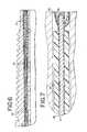
- FIG. 2is a cross-sectional view along line 2 — 2 of FIG. 1 .
- FIG. 3is a cross sectional view along line 3 — 3 of FIG. 1 .
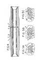
- FIG. 4is a cross-sectional view showing the pin end of FIG. 2 connected to the box end of FIG. 3 .
- FIG. 5Ais an enlarged cross-section of a connection between communication elements of a connected pin and box end.
- FIG. 5Bis an enlarged cross-section of a connection between communication elements of a connected pin and box end, showing the protective bridge on the pin end.
- FIG. 5Cis an enlarged cross-section of a connection between communication elements of a connected pin and box end, showing the protective bridge on the box end.
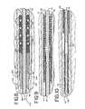
- FIG. 6is a cross-sectional view of the pin end of a drill pipe showing the connector.
- FIG. 7is an enlarged cross-sectional view from FIG. 6 showing the placement of the magnetically connecting, electrically insulating (MCEI) element in the recess of the pin end of a drill pipe.
- MCEImagnetically connecting, electrically insulating
- FIG. 8is an enlarged cross-sectional view from FIG. 6 showing the placement of the expansion plug or mandrel, retaining plug or barbed expansion mandrel, and water-tight seal.
- FIG. 9is an enlarged cross-sectional view from FIG. 6 showing the placement of the centering guide.
- FIG. 10is an enlarged cross-sectional view from FIG. 6 showing the connector and the end of the coaxial cable.
- FIG. 11is a perspective view of the communication element and steel ring.
- FIG. 11Ais a perspective view showing a cross section of the communication element.
- FIG. 12is perspective view of the wire and the wire protection bridge.
- FIG. 13is an enlarged perspective view showing the water-tight seal.
- FIG. 14is an enlarged perspective view of FIG. 12 showing the wire protection bridge.
- FIG. 15is a perspective view of the conductive tube and connection elements.
- FIG. 16is an enlarged perspective view of FIG. 15 showing the centering guide and the connector.
- FIG. 17is an enlarged perspective view of FIG. 15 showing the expansion plug or mandrel and the retaining plug or barbed expansion mandrel.
- downholeis intended to have a relatively broad meaning, including such environments as drilling in oil and gas, gas and geothermal exploration, the systems of casings and other equipment used in oil, gas and geothermal production.
- transmissionas used in connection with the phrase data transmission or the like, is intended to have a relatively broad meaning, referring to the passage of signals in at least one direction from one point to another.
- magnetically conductiverefers to a material having a magnetic permeability greater than that of air.
- electrically insulatingmeans having a high electrical resistivity, preferably greater than that of steel.
- FIG. 1is a perspective view of a section of drill pipe with cutaway sections showing the data transmission system of the present invention.
- the most preferred application of the connectoris in the data transmission system in sections of drill pipe, which make up a drill string used in oil and gas or geothermal exploration.
- the depicted section 15 of FIG. 1includes a pin end 13 , having external tapered threads 19 (see FIG. 2 ), and a box end 11 , having internal tapered threads 21 (see FIG. 3 ). Between the pin end 13 and box end 11 is the body of the section. A typical length of the body is between 30 and 90 feet. Drill strings in oil and gas production can extend as long as 20,000 feet, which means that as many as 700 sections of drill pipe and downhole tools can be used in the drill string.
- the pin end 13includes an external, primary shoulder 37 , and an internal, secondary shoulder or face 35 .
- the box end 11includes an external, primary shoulder 38 and an internal, secondary shoulder or face 36 .
- the pin end 13is threaded into the box end 11 with sufficient force so that the primary external shoulder 37 on the pin end engages the primary shoulder face 38 on the box end.
- the face 35 on the pin endis reliably brought into close proximity or contact with the shoulder 36 on the box end.
- the pin end 13preferably includes a recess 32 in the secondary or internal shoulder or face 35 .
- the recessis located so as to lie equidistant between the inner and outer diameter of the secondary shoulder or face 35 .
- the recessis formed at either the inner or the outer diameter of the face, thereby creating a recess that is open on two sides.
- the recessis machined into the face by conventional tools either before or after the tool joint is attached to the pipe.
- the dimensions of the recesscan be varied depending on various factors. For one thing, it is desirable to form the recess in a location and with a size that will not interfere with the mechanical strength of the pin end. Further, in this orientation, the recesses are located so as to be substantially aligned as the joint is made up. Other factors will be discussed below.
- the recessis preferably configured so as to open axially, that is, in a direction parallel to the length of the drill string.
- the recessesmay be configured so as to open radially, that is, in a direction perpendicular to the length of the drill string. This offset configuration does not materially affect the performance of the inductive elements of the present invention whether in an axial or radial configuration.
- a communication elementlying within the recesses 32 and 34 formed in the Internal pin face 35 and internal shoulder face 36 respectively is a communication element.
- the preferred communication elementis an inductive coil.
- other communication elementssuch as acoustic transceivers, optic fiber couplers and electrical contacts are also benefited by being placed in a recess formed in the internal pin face and internal shoulder face.
- placing the communication elements in recesses within internal facesprovides for better protection from the harsh drilling environment.
- a pipe jointsuch as that shown in FIG. 4 that also includes external abutting faces 37 and 38 , the internal faces 35 and 36 are brought together in a more reliable manner.
- the internal faces 35 and 36are brought together with a more consistent force.
- the internal facesare less than about 0.03′′ apart when the adjacent components are fully threaded together. More preferably, the internal faces are touching. Most preferably, the internal faces are in a state of compression.
- a typical drill pipe alloy4140 alloy steel, having a Rockwell C hardness of 30 to 35, has a magnetic permeability of about 42.
- the magnetic permeability of a materialis defined as the ratio of the magnetic flux density B established within a material divided by the magnetic field strength H of the magnetizing field. It is usually expressed as a dimensionless quantity relative to that of air (or a vacuum). It is preferable to close the magnetic path that couples the adjacent coils with a material having a magnetic permeability higher than the steel. However, if the magnetic material is itself electrically conducting, then it provides an alternate electrical path to that offered by the adjacent loops.
- eddy currentsare believed to be the primary source of the losses experienced in prior-art transformer schemes. Since the magnetic field is in a direction curling around the conductors, there is no need for magnetic continuity in the direction of the loop.
- the communication elementconsists of a steel ring 45 containing a magnetically conducting, electrically insulating (MCEI) element 89 , and a conductive coil 87 lying within the MCEI.
- MCEImagnetically conducting, electrically insulating
- the MCEI elementis magnetically conducting.
- the magnetically conducting componentshould have a magnetic permeability greater than air. Materials having too high of a magnetic permeability tend to have hysteresis losses associated with reversal of the magnetic domains themselves. Accordingly, a material is desired having a permeability sufficiently high to keep the field out of the steel and yet sufficiently low to minimize losses due to magnetic hysteresis.
- the magnetic permeability of the MCEI elementshould be greater than that of steel, which is typically about 40 times that of air, more preferably greater than about 100 times that of air.
- the magnetic permeabilityis less than about 2,000. More preferably, the MCEI element has a magnetic permeability less than about 800. Most preferably, the MCEI element has a magnetic permeability of about 125.
- the MCEIis preferably electrically insulating as well as magnetically conductive.
- the MCEI elementhas an electrical resistivity greater than that of steel, which is typically about 12 micro-ohm cm. Most preferably, the MCEI has an electrical resistivity greater than about one million ohm-cm.
- the MCEI element 89is preferably made from a single material, which itself has the properties of being magnetically conductive and electrically insulating.
- a particularly preferred materialis ferrite. Ferrite is described in the on-line edition of the Encyclopedia Britannica as “a ceramic-like material with magnetic properties that are useful in many types of electronic devices. Ferrites are hard, brittle, iron-containing, and generally gray or black and are polycrystalline—i.e., made up of a large number of small crystals.
- the article on ferritegoes on to say that a “ferrite is formed by the reaction of ferric oxide (iron oxide or rust) with any of a number of other metals, including magnesium, aluminum, barium, manganese, copper, nickel, cobalt, or even iron itself.”
- ferric oxideiron oxide or rust
- any of a number of other metalsincluding magnesium, aluminum, barium, manganese, copper, nickel, cobalt, or even iron itself.
- the article states that the “most important properties of ferritesinclude high magnetic permeability and high electrical resistance.” Consequently, some form of ferrite is ideal for the MCEI element in the present invention.
- the ferriteis one commercially available from Fair-Rite Products Corp., Wallikill, N.Y., grade 61, having a magnetic permeability of about 125.
- Another preferred commercial supplier of ferriteis Gascyl Ent., Coquitlan, B. C., Canada. There are a number of other manufacturers that provide commercial products having a corresponding grade
- the MCEI elementcan be made from a combination of materials selected and configured to give these properties to the element as a whole.
- the elementcan be made from a matrix of particles of one material that is magnetically conductive and particles of another material that is electrically insulating, wherein the matrix is designed so as to prevent the conduction of electrical currents, while promoting the conduction of a magnetic current.
- the MCEI elementmay be formed from laminations of a material such as a silicon transformer steel separated by an electrically insulating material, such as a ceramic, mineral (mica), or a polymer. Because the induced electric field is always perpendicular to the magnetic field, the chief requirement for the MCEI element is that the magnetic field be accommodated in a direction that wraps around the coil, whereas electrical conduction should be blocked in the circumferential direction, perpendicular to the magnetic field and parallel to the coil.
- the communication element 91contains an MCEI element.
- the MCEI elementis formed from several segments of ferrite 83 which are held together in the appropriate configuration by means of a resilient material, such as an epoxy, a natural rubber, polytetrafluoroethylene (PTFE), perfluoroalkoxy (PFA), a fiberglass or carbon fiber composite, or a polyurethane.
- a preferred method of forming a segmented MCEI elementbegins with providing a steel ring 45 having a generally unshaped trough conforming to the final dimensions of the MCEI element.
- the steel ring 45has ridges 99 around its circumference in order to enhance the connection of the steel ring to the drill pipe.
- the element 99is preferably manufactured as a complete unit and is then inserted into the drill pipe, the final assembly configuration being shown in FIGS. 8, 9 , and 10 .
- a two-part, heat-curable epoxy formulationis mixed in a centrifuge cup. If the ferrite elements have some porosity, they can be sealed by being centrifuged for up to 30 minutes to cause all bubbles induced by mixing to rise out of the viscous liquid, and to cause the liquid to penetrate and seal any porosity in the ferrite. Most preferably, a grade of ferrite is used which has very low porosity which does not require sealing in this fashion.
- the individual u-shaped ferrite segmentsare then placed in the metal ring, except for a gap surrounding the retaining bridge 43 , as shown in FIGS. 12 and 14.) Any excess epoxy is wiped out of the unshaped groove.
- the upper surfaces of the partscan be precisely aligned with each other by holding them in position with magnets placed around the u-shaped trough in the mold. The epoxy is then cured, either at room temperature or in an oven.
- the entire communication element 91may be preassembled before the communication element 91 is inserted in the drill pipe, which can optionally be done in the field.
- the steel ring 45has the advantage that it provides a durable frame upon which to house the relatively fragile MCEI.
- the communication element 91may be retained in the recess 32 of FIG. 2 by means of a polymeric bonding material, preferably epoxy, polyurethane, polytetrafluoroethylene, or perfluoroalkoxy, most preferably epoxy. Most preferably, the communication element 91 is retained in recess 32 by means of a press fit.
- the communication element 91preferably comprises a steel ring 45 , an MCEI element, and a conductive coil 87 . Lying within the trough of the MCEI element 89 is the electrically conductive coil 87 .
- This coilis preferably made from at least one loop of an insulated wire, most preferably only a single loop.
- the wireis preferably made of copper, most preferably of silver-plated copper-clad steel, and is and insulated with varnish, enamel, or a polymer. Most preferably, the wire is insulated with a tough, flexible polymer such as high density polyethylene or polymerized tetrafluoroethane (PTFE).
- the diameter of the wire, with insulation,is preferably selected so as to be slightly less than the width of the U-shaped trough in the MCEI element. As will be discussed below, the specific properties of the wire and the number of loops is important in providing proper impedance for the coil 87 .
- the communication element 91has a first and second contact for connecting to the coaxial cable 51 .
- the first contactis preferably one end of the coil 87 .
- the first contactis preferably retained in the communication element by a retention bridge 43 .
- the retention bridge 43is preferably inserted in a hole in the steel ring 45 , holding the first contact in place and preventing the first contact from coming into electrical contact with the second contact.
- the retention bridge 43is made from an electrically insulating material, preferably PTFE, more preferably PEEK®.
- PEEK®is a trademark for a linear aromatic, semi-crystalline, polyetheretherketone thermoplastic polymer manufactured by Victrex PLC. A typical supplier for such material is Zeus Products, Orangeburg, S.C.
- the second contact of the communication element 91is in electrical contact with the steel ring 45 , preferably by means of a welded connection 85 .
- the transformer diameteris fixed by the diameter of the pipe.
- the impedance of the transformer, and its desired operating frequencycan be adjusted by two factors: the number of turns in the conductor and the ratio of length to area of the magnetic path, which curls around the conductors. Increasing the number of turns decreases the operating frequency and increases the impedance. Lengthening the magnetic path, or making it narrower, also decreases the operating frequency and increases the impedance. This is accomplished by increasing the depth of the U-shaped trough or by decreasing the thickness of the side-walls. Adjusting the number of turns gives a large increment, while adjusting the dimensions of the trough enables small increments.
- the inventionallows the impedance of the transformer portion of the transmission line to be precisely matched to that of the conductor portion, which is typically in the range of 30 to 120 ohms.
- the conductor portionwhich is typically in the range of 30 to 120 ohms.
- an insulated copper wireis preferred, other electrically conductive materials, such as silver or copper-coated steel, can be used to form the coil 87 .
- the coil 87is embedded within a material which fills the space within the trough of the MCEI element 89 .
- this materialshould be electrically insulating. It is also preferable that this material is resilient so as to add further toughness to the MCEI element.
- the preferred material to use for this purposeis a two-part epoxy formulation, preferably one filled with a powdered material such as fumed silica or fine aluminum oxide to provide abrasion resistance.
- the applicantshave used standard commercial grade epoxy combined with a ceramic filler material, such as aluminum oxide, in proportions of about 50/50 percent.
- the filler materialshould not be less than 3 percent nor greater than 90 percent in order to achieve suitable abrasion resistance as well as adequate adhesiveness.
- other materialssuch as room-temperature curable urethanes, are used. It is important that the material be able to withstand the extreme conditions found downhole. Consequently, it is important to treat the material in such a way as to ensure the absence of voids or air pockets.
- the box end 11also includes a recess 34 similar to the recess 32 in the pin end, except that the recess 34 is formed in the internal, secondary shoulder 36 of the box end.
- a communication element 92similar in all respects to the communication element 90 , is located within the recess 34 .
- the communication element 90 of the pin end and the communication element 92 of the box endare brought to at least close proximity.
- the elements 90 and 92are within about 0.5 mm of each other, more preferably within about 0.25 mm of each other.
- the elements 27 and 29are in contact with each other.
- the troughs in the pin and box endmay need to be machined in the field after extended use, it may preferred to design the troughs in the pin and box end with a shape and size so as to allow the first and second conductive coils to lie in the bottom of the respective troughs and still be separated a distance from the top of the respective first and second sides.
- this distanceis preferably at least about 0.01 inches, more preferably, this distance is at least about 0.06 inches.
- the passages 23 and 25are holes, preferably drilled from one point in the bottom of the recess 32 and 34 , respectively, through the enlarged wall of the pin end and box end, respectively, so that the holes open into the central bore of the pipe section 15 .
- the diameter of the holewill be determined by the thickness available in the particular joint. For reasons of structural integrity it is preferably less than about one half of the wall thickness. Preferably, these holes have a diameter of about between 3 and 7 mm.
- the diameter of the passages 23 and 25preferably increases slightly towards the pin recess 32 and the box recess 34 . These larger diameter sections towards the pin recess 32 and the box recess 34 are called the pin connector channel 31 and the box connector channel 33 .
- These two holescan be drilled by conventional means. Preferably, they are drilled by a technique known as gun drilling. Preferably, the recesses can be machined and the holes can be drilled in the field, so as to allow for retrofitting of existing drill pipe sections with the data transmission system of the present invention in the field.
- a conductive tube 71is placed within the passages 23 and 25 .
- the conductive tube 71runs almost the entire length of the drill pipe, beginning in the pin end connector channel 31 , continuing through the pin end passage 23 , passing through the hole 93 to enter the interior of the body of the pipe section, entering hole 95 , continuing through the box end passage 25 , and ending near the box end connector channel 33 .
- the conductive tube 71is preferably held in tension after it is inserted in the drill pipe 15 and remains in tension during downhole use. This prevents the conductive tube 71 from moving relative to the passages 23 and 25 during downhole use.
- the conductive tubeis preferably made of metal, more preferably a strong metal, most preferably steel. By “strong metal” it is meant that the metal is relatively resistant to deformation in its normal use state.
- the metalis preferably stainless steel, most preferably 316 or 316L stainless steel. A preferred supplier of stainless steel is National Tube, Salisbury, Md.
- FIGS. 6 through 10are enlarged cross sectional views of FIG. 6 from right to left, with FIG. 7 showing an enlarged view of the right end of FIG. 6, FIGS. 8 and 9 showing enlarged views of the center, and FIG. 10 showing an enlarged view of the left side of FIG. 6 .
- FIG. 15is a perspective view of the conductive tube and connection elements and FIG. 17 is an enlarged perspective view of the conductive tube retainer elements.
- the conductive tubeis held in place in each end by means of an expansion plug or mandrel 61 and a retaining plug or barbed expansion mandrel 63 , as shown in FIGS. 6 and 8.
- the expansion plug 61preferably increases in diameter from front 62 to back 64 , such that the diameter of the back 64 is larger than the initial inner diameter 104 of the conductive tube 71 and the front 62 is smaller than the initial conductive tube inner diameter 104 as shown best in FIGS. 15 and 17.
- the expansion plug or mandrel 61has a center opening 101 through which the wire 41 passes and is preferably made of metal, more preferably tool steel, most preferably Viscount 44 steel. The center opening 101 as shown in FIG.
- the expansion plug or mandrelcan also be made of steel, titanium, chrome, nickel, aluminum, iron, copper, tin, and lead. Additionally it can be made of stainless steels and 4100 series steels. Most preferably, the expansion mandrel hardness is at least 30 on a Rockwell C hardness scale. In another embodiment, the expansion mandrel can be made of a ceramic such as cemented tungsten carbide, alumina, silicon carbide, silicone nitride, and polycrystalline diamond.
- the expansion plug or mandrel 61is inserted up to a distance relatively near the transition point 97 , where the diameter of the passage 31 or 33 undergoes a change in diameter.
- the change in diameterresults in the passageway forming complimentary recesses 105 and 106 with the first outer diameter 102 and second outer diameter 103 of the conductive tube.
- the complimentary recessescan be formed by means of gun drilled hole with a counter bore at each end of the gun drilled hole.
- the passagewaycan be the result of two or more complimentary recesses. These multiple recesses can be formed by multiple counter bores at each end of the gun drilled hole.
- the result of this insertion of the expansion plug or mandrel 61is that the diameter of the conductive tube 71 is larger on each end, so that the conductive tube 71 is held in place in the passages 31 and 33 .
- the expansion plug or mandrel 61is held in place by a retaining plug or barbed expansion mandrel 63 , as shown in FIG. 8 .
- the retaining plug or barbed expansion mandrel 63is placed in the conductive tube 71 after the expansion plug or mandrel 61 and has a center opening through which the wire 41 passes.
- the center opening through which the wire 41 passescould also be electrically insulated.
- the retaining plug or barbed expansion mandrel 63is made of metal, more preferably tool steel, most preferably Viscount 44 steel.
- the retaining plug or barbed expansion mandrelcan also be made of steel, titanium, chrome, nickel, aluminum, iron, copper, tin, and lead.
- the barbed expansion mandrel hardnessis at least 30 on a Rockwell C hardness scale.
- the barbed expansion mandrelcan be made of a ceramic such as cemented tungsten carbide, alumina, silicon carbide, silicone nitride, and polycrystalline diamond.
- the retaining plug or barbed expansion mandrel 63has ridges along its outer diameter to dig into the inner diameter of the conductive tube 71 and hold the expansion plug or mandrel 61 in place.
- the conductive tube outer diameter 102can also be press-fit into the passageway 105 .
- the conductive tubeis in tension within the passageway of the pipe. The preferred amount of tension is between 300 and 1200 pounds-force.
- the conductive tube 71After exiting the holes 93 and 95 , the conductive tube 71 passes through the interior of the body of the pipe section.
- the conductive tubemay be insulated from the pipe in order to prevent possible galvanic corrosion.
- the preferred material with which to insulate the conductive tube 71is PEEK®.
- the coaxial cable 51runs inside the conductive tube 71 .
- the coaxial cable 51has a conductive core 79 surrounded by a dielectric sheath 81 .
- the coaxial cable 71also has a conductive sheath surrounding the dielectric sheath 81 and in electrical contact with the conductive tube 71 .
- the coaxial dielectric sheath 71prevents electrical contact between the coaxial core 79 and the conductive tube 71 . As shown in FIG.
- an inner layer of the dielectric sheath 81is removed from around the conductive core 79 at each end, while leaving the outer layer of the dielectric sheath 81 in place next to the conductive tube 71 . This allows insertion of the connector 53 around the conductive core 79 and within the dielectric sheath 81 .
- the coaxial cablepreferably has a characteristic impedance in the range of about 30 to about 120 ohms, most preferably with a characteristic impedance in the range of 50 to 75 ohms. Because the attenuation of coaxial cable decreases with increasing diameter, the largest diameter compatible with installation in pipe chosen for a particular application should be used. Most preferably the cable has a diameter of about 0.25′′ or larger.
- the shieldshould provide close to 100% coverage, and the core insulation should be made of a fully-dense polymer having low dielectric loss, most preferably from the family of polytetrafluoroethylene (PTFE) resins, Dupont's Teflon® being one example. A foamed polymer may also be used as the core insulation.
- PTFEpolytetrafluoroethylene
- the ratio of the impedance of the electrical conductor to the impedance of the first and second electrically conductive coilsis between about 1:2 and 2:1. Most preferably, it is close to 1:1.
- the preferred data transmission systemprovides a relatively broad bandwidth. While not wishing to be bound by any particular theory, it is currently believed that this is accomplished by the low number of turns of the conductor and the low reluctance of the magnetic path, thus producing a surprisingly low mutual inductance for such a large diameter coil.
- the mutual inductance of the assembled toroidis about 1 micro Henry.
- peak signal transmissionis at about 4 MHz, and at power transmission extends from about 1 MHz to about 12 MHz.
- the inductive reactanceis about 65 ohms, and the attenuation is only about 0.35 dB per joint, equivalent to power transmission of about 92 percent.
- the communication elementis thought to perform as a transmission-line transformer, wherein the coupling between the adjacent coils comprises distributed elements of both capacitance and inductance.
- the term “inductive coil”is intended to include both coils that transfer signals via induction as well as those coils that act as a transmission-line transformer.
- a serial filteris created, which has the effect of reducing the bandwidth. If each individual transformer had a narrow bandwidth, the band-pass of the filter would change as additional segments are added, which would require that each individual element be separately tuned according to its position in the system.
- a surprising feature of the inventionis that identical segments can be assembled in any arbitrary number of joints while still enabling efficient signal coupling.
- a connector 53in both the pin connector channel 31 and the box connector channel 33 is a connector 53 .
- the connector 53permits the coaxial cable 51 to transmit an electrical signal to the communication element 91 .
- the connector 53has a conductive sleeve 75 which fits around the conductive core 79 .
- the connector 53has an insulative coating 77 to prevent electrical contact between the conductive sleeve 75 and the conductive tube 71 .
- the insulative coatingis TEFLON®.
- the connector 53is pushed over the conductive core 79 , making electrical contact with it.
- the connector 53makes spring contact with the conductive core 79 .
- connector 53fits around a wire 41 , which is in electrical contact with the communication element 91 .
- the wire 41is one end of the conductive coil 87 .
- the wire 41is preferably made of copper or silver-plated, copper-clad steel.
- the wire 41has an insulative coating 59 , which is made of varnish, enamel, or a polymer.
- the insulative coating 59is a tough, flexible polymer such as high density polyethylene or polymerized tetrafluoroethane (PTFE).
- PTFEpolymerized tetrafluoroethane
- the insulative coating 59 of the wire 41is removed on the end of the wire 41 closest to the connector 53 , in order to facilitate electrical contact between the conductive sleeve 75 and the wire 41 .
- the connector 53is crimped around the wire 41 in order to ensure good electrical contact between the conductive sleeve 75 and the wire 41 .
- a centering insulator 73is used to help position the connector 53 .
- the centering insulator 73is funnel-shaped at each end and is made of a dielectric material, preferably PTFE, most preferably PEEK®.
- the centering insulator 73is hollow in the center, allowing it to slide around the connector 53 and guide the connector 53 towards the core 79 .
- a water-tight seal 55is present in both the pin end connector channel 31 and the box end connector channel 33 to protect the connections from the high temperature and high pressure downhole conditions.
- a spacer 65is placed between the retaining plug or barbed expansion mandrel 63 and the water-tight seal.
- the spacer 65is made of fiberglass.
- the seal 55is located proximate to the retaining plug or barbed expansion mandrel, as shown in FIG. 8, and forms a seal between the inner surface of the conductive tube 71 and the outer surface of the wire 41 .
- the sealcomprises at least one O-ring 67 and at least one backup 69 .
- the O-rings 67are preferably made of rubber, more preferably fluoroelastomer, most preferably a fluoroelastomer marketed under the trademark AFLAS® or VITON®.
- the backups 69are preferably made of PEEKS and have a v-shaped indentation around one end. As an O-ring 67 is compressed, it moves into the indentation in the backup 69 and causes the outer diameter of the backup 69 to press against the conductive tube 71 and the inner diameter to press against the wire 41 , thus helping to maintain the water-tight seal.
- a water-tight sealis present between the connector 53 and the inner surface of the conductive tube 71 .
- the sealis provided by at least one circumferential groove on the outside of the connector and at least one gasket fitting therein.
- Alternate embodimentsmay protect the connection with a water tight seal in other locations, such as between the coaxial core 79 and the conductive tube 71 , between the connector 53 and the conductive tube 71 , and between the wire 41 and the connecting channels 31 and 33 .
- Many types of data sourcesare important to management of a drilling operation. These include parameters such as hole temperature and pressure, salinity and pH of the drilling mud, magnetic declination and horizontal declination of the bottom-hole assembly, seismic look-ahead information about the surrounding formation, electrical resistivity of the formation, pore pressure of the formation, gamma ray characterization of the formation, and so forth.
- the high data rate provided by the present inventionprovides the opportunity for better use of this type of data and for the development of gathering and use of other types of data not presently available.
- the systemwill transmit data at a rate of at least 100 bits/second, more preferably, at least 20,000 bits/second, and most preferably, at least about 2,000,000 bits/second.
- the systempreferably transmits data through at least 30 components powered only by the varying current supplied to one of the first conductive coils in one of the components. More preferably, the system transmits data through at least 50 components powered only by the varying current supplied to one of the first conductive coils in one of the components.
- the varying current supplied to the first conductive coil in the one componentis driving a varying potential having a peak to peak value of between about 10 mV and about 20 V.
- the power loss between two connected componentsis less than about 5 percent.
- the transmission line of the inventionwill typically transmit the information signal a distance of 1,000 to 2,000 feet before the signal is attenuated to the point where it will require amplification. This distance can be increased by sending a stronger signal, with attendant increased power consumption. However, many wells are drilled to depths of up to 20,000 to 30,000 feet, which would necessitate use of repeaters to refurbish the signal.
- the amplifying unitsare provided in no more than 10 percent of the components in the string of downhole components, more preferably, no more than 3 percent.
- Such repeaterscan be simple “dumb” repeaters that only increase the amplitude of the signal without any other modification.
- a simple amplifierwill also amplify any noise in the signal.
- a digital repeaterwill provide a fresh signal without amplifying background noise.
- a “smart” repeaterthat detects any errors in the data stream and restores the signal, error free, while eliminating baseline noise, is preferred. Any of a number of known digital error correction schemes can be employed in a down-hole network incorporating a “smart” repeater.
- the repeaternot only serves to regenerate the data stream, but also serves as a data source itself.
- informationwas available during drilling only from the bottom-hole assembly, as mud pulse data rates did not allow any intermediate nodes.
- informationis available from any node along the drill string, thereby enabling distributed access to information from top to bottom. For instance, instead of relying on a single bottom hole pressure measurement, a pressure profile can now be generated along the entire drill string. This could be vital in underbalanced drilling, where to speed up drilling the pressure provided by the mud is less than that of the pore pressure in the surrounding formation. Any sudden pressure pulse or “kick” could be much more rapidly anticipated.
- inclinometersthermocouples
- gamma ray detectorsgamma ray detectors
- acoustic wave detectorsneutron sensors
- pressure transducerspotentiometers
- strain gagesseismic sources, and seismic receivers.
Landscapes
- Engineering & Computer Science (AREA)
- Mining & Mineral Resources (AREA)
- Life Sciences & Earth Sciences (AREA)
- Geology (AREA)
- Physics & Mathematics (AREA)
- Power Engineering (AREA)
- Mechanical Engineering (AREA)
- Fluid Mechanics (AREA)
- Environmental & Geological Engineering (AREA)
- General Life Sciences & Earth Sciences (AREA)
- Geochemistry & Mineralogy (AREA)
- Remote Sensing (AREA)
- General Engineering & Computer Science (AREA)
- Electromagnetism (AREA)
- Geophysics (AREA)
- Coupling Device And Connection With Printed Circuit (AREA)
Abstract
Description
Claims (23)
Priority Applications (1)
| Application Number | Priority Date | Filing Date | Title |
|---|---|---|---|
| US10/427,522US6830467B2 (en) | 2003-01-31 | 2003-04-30 | Electrical transmission line diametrical retainer |
Applications Claiming Priority (3)
| Application Number | Priority Date | Filing Date | Title |
|---|---|---|---|
| US44410003P | 2003-01-31 | 2003-01-31 | |
| US10/358,099US6844498B2 (en) | 2003-01-31 | 2003-02-02 | Data transmission system for a downhole component |
| US10/427,522US6830467B2 (en) | 2003-01-31 | 2003-04-30 | Electrical transmission line diametrical retainer |
Related Parent Applications (1)
| Application Number | Title | Priority Date | Filing Date |
|---|---|---|---|
| US10/358,099Continuation-In-PartUS6844498B2 (en) | 2003-01-31 | 2003-02-02 | Data transmission system for a downhole component |
Publications (2)
| Publication Number | Publication Date |
|---|---|
| US20040219831A1 US20040219831A1 (en) | 2004-11-04 |
| US6830467B2true US6830467B2 (en) | 2004-12-14 |
Family
ID=46123443
Family Applications (1)
| Application Number | Title | Priority Date | Filing Date |
|---|---|---|---|
| US10/427,522Expired - LifetimeUS6830467B2 (en) | 2003-01-31 | 2003-04-30 | Electrical transmission line diametrical retainer |
Country Status (1)
| Country | Link |
|---|---|
| US (1) | US6830467B2 (en) |
Cited By (96)
| Publication number | Priority date | Publication date | Assignee | Title |
|---|---|---|---|---|
| US20040145492A1 (en)* | 2000-07-19 | 2004-07-29 | Hall David R. | Data Transmission Element for Downhole Drilling Components |
| US20040150533A1 (en)* | 2003-02-04 | 2004-08-05 | Hall David R. | Downhole tool adapted for telemetry |
| US20040164833A1 (en)* | 2000-07-19 | 2004-08-26 | Hall David R. | Inductive Coupler for Downhole Components and Method for Making Same |
| US20040242044A1 (en)* | 2001-06-26 | 2004-12-02 | Philip Head | Electrical conducting system |
| US20040246142A1 (en)* | 2003-06-03 | 2004-12-09 | Hall David R. | Transducer for downhole drilling components |
| US20050029034A1 (en)* | 2002-02-19 | 2005-02-10 | Volvo Lastvagnar Ab | Device for engine-driven goods vehicle |
| US20050035876A1 (en)* | 2003-08-13 | 2005-02-17 | Hall David R. | Method for Triggering an Action |
| US20050046590A1 (en)* | 2003-09-02 | 2005-03-03 | Hall David R. | Polished downhole transducer having improved signal coupling |
| US20050046586A1 (en)* | 2002-12-10 | 2005-03-03 | Hall David R. | Swivel Assembly |
| US20050150653A1 (en)* | 2000-07-19 | 2005-07-14 | Hall David R. | Corrosion-Resistant Downhole Transmission System |
| US20050161215A1 (en)* | 2003-07-02 | 2005-07-28 | Hall David R. | Downhole Tool |
| US20050279508A1 (en)* | 2003-05-06 | 2005-12-22 | Hall David R | Loaded Transducer for Downhole Drilling Components |
| US20050285751A1 (en)* | 2004-06-28 | 2005-12-29 | Hall David R | Downhole Drilling Network Using Burst Modulation Techniques |
| US20050284663A1 (en)* | 2002-12-10 | 2005-12-29 | Hall David R | Assessing down-hole drilling conditions |
| US20050285705A1 (en)* | 2004-06-28 | 2005-12-29 | Hall David R | Element of an inductive coupler |
| US20050284662A1 (en)* | 2004-06-28 | 2005-12-29 | Hall David R | Communication adapter for use with a drilling component |
| US20050284659A1 (en)* | 2004-06-28 | 2005-12-29 | Hall David R | Closed-loop drilling system using a high-speed communications network |
| US20050285754A1 (en)* | 2004-06-28 | 2005-12-29 | Hall David R | Downhole transmission system |
| US20050285752A1 (en)* | 2004-06-28 | 2005-12-29 | Hall David R | Down hole transmission system |
| US20050285645A1 (en)* | 2004-06-28 | 2005-12-29 | Hall David R | Apparatus and method for compensating for clock drift in downhole drilling components |
| US20060016590A1 (en)* | 2004-07-22 | 2006-01-26 | Hall David R | Downhole Component with A Pressure Equalization Passageway |
| US20060021799A1 (en)* | 2004-07-27 | 2006-02-02 | Hall David R | Biased Insert for Installing Data Transmission Components in Downhole Drilling Pipe |
| US20060022839A1 (en)* | 2004-08-02 | 2006-02-02 | Hall David R | Modulation System for Communication |
| US20060033637A1 (en)* | 2004-07-27 | 2006-02-16 | Intelliserv, Inc. | System for Configuring Hardware in a Downhole Tool |
| US20060062249A1 (en)* | 2004-06-28 | 2006-03-23 | Hall David R | Apparatus and method for adjusting bandwidth allocation in downhole drilling networks |
| US20060065444A1 (en)* | 2004-09-28 | 2006-03-30 | Hall David R | Filter for a Drill String |
| US20060065443A1 (en)* | 2004-09-28 | 2006-03-30 | Hall David R | Drilling Fluid Filter |
| US20060174702A1 (en)* | 2005-02-04 | 2006-08-10 | Hall David R | Transmitting Data through a Downhole Environment |
| US20060225926A1 (en)* | 2005-03-31 | 2006-10-12 | Schlumberger Technology Corporation | Method and conduit for transmitting signals |
| US7132904B2 (en) | 2005-02-17 | 2006-11-07 | Intelliserv, Inc. | Apparatus for reducing noise |
| US7135933B2 (en) | 2004-09-29 | 2006-11-14 | Intelliserv, Inc. | System for adjusting frequency of electrical output pulses derived from an oscillator |
| US20060255851A1 (en)* | 2005-05-16 | 2006-11-16 | Marshall Soares | Stabilization of state-holding circuits at high temperatures |
| US20060256718A1 (en)* | 2005-05-16 | 2006-11-16 | Hall David R | Apparatus for Regulating Bandwidth |
| US20060260801A1 (en)* | 2005-05-21 | 2006-11-23 | Hall David R | Wired Tool String Component |
| US20060260798A1 (en)* | 2005-05-21 | 2006-11-23 | Hall David R | Wired Tool String Component |
| US20060289074A1 (en)* | 2005-06-27 | 2006-12-28 | Ntnu Technology Transfer As | Pipe with a canal in the pipe wall |
| US20070018847A1 (en)* | 2005-07-20 | 2007-01-25 | Hall David R | Laterally Translatable Data Transmission Apparatus |
| US20070023190A1 (en)* | 2005-07-29 | 2007-02-01 | Hall David R | Stab Guide |
| US20070023185A1 (en)* | 2005-07-28 | 2007-02-01 | Hall David R | Downhole Tool with Integrated Circuit |
| US20070056723A1 (en)* | 2005-09-12 | 2007-03-15 | Intelliserv, Inc. | Hanger Mounted in the Bore of a Tubular Component |
| US20070063865A1 (en)* | 2005-09-16 | 2007-03-22 | Schlumberger Technology Corporation | Wellbore telemetry system and method |
| US7254822B2 (en) | 2003-08-07 | 2007-08-07 | Benq Corporation | Disk drive avoiding flying disk |
| US20070181296A1 (en)* | 2006-02-08 | 2007-08-09 | David Hall | Self-expandable Cylinder in a Downhole Tool |
| US20070188344A1 (en)* | 2005-09-16 | 2007-08-16 | Schlumberger Technology Center | Wellbore telemetry system and method |
| US20070194946A1 (en)* | 2006-02-06 | 2007-08-23 | Hall David R | Apparatus for Interfacing with a Transmission Path |
| US20070257811A1 (en)* | 2006-04-21 | 2007-11-08 | Hall David R | System and Method for Wirelessly Communicating with a Downhole Drill String |
| US7304835B2 (en) | 2005-04-28 | 2007-12-04 | Datavan International Corp. | Mainframe and power supply arrangement |
| US20070278009A1 (en)* | 2006-06-06 | 2007-12-06 | Maximo Hernandez | Method and Apparatus for Sensing Downhole Characteristics |
| US20080003894A1 (en)* | 2006-07-03 | 2008-01-03 | Hall David R | Wiper for Tool String Direct Electrical Connection |
| US20080003856A1 (en)* | 2006-07-03 | 2008-01-03 | Hall David R | Downhole Data and/or Power Transmission System |
| US20080024318A1 (en)* | 2006-07-06 | 2008-01-31 | Hall David R | System and Method for Sharing Information between Downhole Drill Strings |
| US20080047753A1 (en)* | 2004-11-05 | 2008-02-28 | Hall David R | Downhole Electric Power Generator |
| US20080110638A1 (en)* | 2006-11-14 | 2008-05-15 | Hall David R | Power and/or Data Connection in a Downhole Component |
| US20080166917A1 (en)* | 2007-01-09 | 2008-07-10 | Hall David R | Tool String Direct Electrical Connection |
| US20080202765A1 (en)* | 2007-02-27 | 2008-08-28 | Hall David R | Method of Manufacturing Downhole Tool String Components |
| US20080223569A1 (en)* | 2006-07-03 | 2008-09-18 | Hall David R | Centering assembly for an electric downhole connection |
| US20080309514A1 (en)* | 2007-06-12 | 2008-12-18 | Hall David R | Data and/or PowerSwivel |
| US7504963B2 (en) | 2005-05-21 | 2009-03-17 | Hall David R | System and method for providing electrical power downhole |
| US20090101328A1 (en)* | 2004-09-28 | 2009-04-23 | Advanced Composite Products & Technology, Inc. | Composite drill pipe and method of forming same |
| US7537053B1 (en) | 2008-01-29 | 2009-05-26 | Hall David R | Downhole electrical connection |
| US7548068B2 (en) | 2004-11-30 | 2009-06-16 | Intelliserv International Holding, Ltd. | System for testing properties of a network |
| US20090166031A1 (en)* | 2007-01-25 | 2009-07-02 | Intelliserv, Inc. | Monitoring downhole conditions with drill string distributed measurement system |
| US20090267790A1 (en)* | 2008-04-24 | 2009-10-29 | Hall David R | Changing Communication Priorities for Downhole LWD/MWD Applications |
| US20100116550A1 (en)* | 2005-08-04 | 2010-05-13 | Remi Hutin | Interface and method for wellbore telemetry system |
| US20100186944A1 (en)* | 2009-01-23 | 2010-07-29 | Hall David R | Accessible Downhole Power Assembly |
| US20100236833A1 (en)* | 2009-03-17 | 2010-09-23 | Hall David R | Displaceable Plug in a Tool String Filter |
| US20110017334A1 (en)* | 2009-07-23 | 2011-01-27 | Baker Hughes Incorporated | Wired conduit segment and method of making same |
| US20110217861A1 (en)* | 2009-06-08 | 2011-09-08 | Advanced Drilling Solutions Gmbh | Device for connecting electrical lines for boring and production installations |
| US8049506B2 (en) | 2009-02-26 | 2011-11-01 | Aquatic Company | Wired pipe with wireless joint transceiver |
| US8061443B2 (en) | 2008-04-24 | 2011-11-22 | Schlumberger Technology Corporation | Downhole sample rate system |
| CN102395746A (en)* | 2009-03-30 | 2012-03-28 | 瓦姆钻杆钻具法国公司 | Wired drill pipe with improved configuration |
| US8264369B2 (en) | 2005-05-21 | 2012-09-11 | Schlumberger Technology Corporation | Intelligent electrical power distribution system |
| US8267196B2 (en) | 2005-11-21 | 2012-09-18 | Schlumberger Technology Corporation | Flow guide actuation |
| US8281882B2 (en) | 2005-11-21 | 2012-10-09 | Schlumberger Technology Corporation | Jack element for a drill bit |
| US8297375B2 (en) | 2005-11-21 | 2012-10-30 | Schlumberger Technology Corporation | Downhole turbine |
| US8360174B2 (en) | 2006-03-23 | 2013-01-29 | Schlumberger Technology Corporation | Lead the bit rotary steerable tool |
| US8522897B2 (en) | 2005-11-21 | 2013-09-03 | Schlumberger Technology Corporation | Lead the bit rotary steerable tool |
| US8704677B2 (en) | 2008-05-23 | 2014-04-22 | Martin Scientific Llc | Reliable downhole data transmission system |
| US20140144614A1 (en)* | 2012-11-28 | 2014-05-29 | Robert Buda | Wired pipe coupler connector |
| US20140144537A1 (en)* | 2012-11-28 | 2014-05-29 | Volker Peters | Wired pipe coupler connector |
| US8826972B2 (en) | 2005-07-28 | 2014-09-09 | Intelliserv, Llc | Platform for electrically coupling a component to a downhole transmission line |
| US8833472B2 (en) | 2012-04-10 | 2014-09-16 | Halliburton Energy Services, Inc. | Methods and apparatus for transmission of telemetry data |
| US8986028B2 (en)* | 2012-11-28 | 2015-03-24 | Baker Hughes Incorporated | Wired pipe coupler connector |
| WO2015051165A1 (en)* | 2013-10-02 | 2015-04-09 | Darren Wall | Inductive coupler assembly for downhole transmission line |
| US9052043B2 (en)* | 2012-11-28 | 2015-06-09 | Baker Hughes Incorporated | Wired pipe coupler connector |
| US9121962B2 (en) | 2005-03-31 | 2015-09-01 | Intelliserv, Llc | Method and conduit for transmitting signals |
| US9157313B2 (en) | 2012-06-01 | 2015-10-13 | Intelliserv, Llc | Systems and methods for detecting drillstring loads |
| US9243489B2 (en) | 2011-11-11 | 2016-01-26 | Intelliserv, Llc | System and method for steering a relief well |
| US9255451B2 (en) | 2013-01-29 | 2016-02-09 | Baker Hughes Incorporated | Tube locking mechanism for downhole components |
| US9494033B2 (en) | 2012-06-22 | 2016-11-15 | Intelliserv, Llc | Apparatus and method for kick detection using acoustic sensors |
| US9759017B2 (en) | 2013-01-30 | 2017-09-12 | Baker Hughes Incorporated | Maintaining tension of a transmission line in a tubular |
| US9850718B2 (en) | 2013-08-07 | 2017-12-26 | Baker Hughes, A Ge Company Llc | Retention device for drill pipe transmission line |
| US10218074B2 (en) | 2015-07-06 | 2019-02-26 | Baker Hughes Incorporated | Dipole antennas for wired-pipe systems |
| US10329856B2 (en) | 2015-05-19 | 2019-06-25 | Baker Hughes, A Ge Company, Llc | Logging-while-tripping system and methods |
| US10342958B2 (en) | 2017-06-30 | 2019-07-09 | Abbott Cardiovascular Systems Inc. | System and method for correcting valve regurgitation |
| US10404007B2 (en) | 2015-06-11 | 2019-09-03 | Nextstream Wired Pipe, Llc | Wired pipe coupler connector |
Families Citing this family (12)
| Publication number | Priority date | Publication date | Assignee | Title |
|---|---|---|---|---|
| US7548681B2 (en)* | 2006-11-30 | 2009-06-16 | Schlumberger Technology Corporation | Prevention of optical fiber darkening |
| US8684096B2 (en)* | 2009-04-02 | 2014-04-01 | Key Energy Services, Llc | Anchor assembly and method of installing anchors |
| US9303477B2 (en) | 2009-04-02 | 2016-04-05 | Michael J. Harris | Methods and apparatus for cementing wells |
| AT508306B1 (en)* | 2009-06-08 | 2013-01-15 | Advanced Drilling Solutions Gmbh | CONNECTION BETWEEN A STARTER EAR AND A CONNECTOR |
| FR2984395B1 (en)* | 2011-12-19 | 2013-12-27 | Vallourec Mannesmann Oil & Gas | TUBULAR COMPONENT FOR DRILLING AND OPERATING HYDROCARBON WELLS AND RESULTING THREAD |
| US10221632B2 (en)* | 2013-03-14 | 2019-03-05 | Ge Energy Oilfield Technology, Inc | Composite isolation joint for gap sub or internal gap |
| CN203721972U (en)* | 2013-12-11 | 2014-07-16 | 常州安费诺福洋通信设备有限公司 | Waterproof device for cable assembly and connector |
| CN111236857A (en)* | 2020-02-20 | 2020-06-05 | 北京中煤矿山工程有限公司 | Double-shoulder anti-torque drill rod of raise boring machine capable of transmitting data |
| CN112681985B (en)* | 2020-12-28 | 2022-11-01 | 中海石油(中国)有限公司 | Intelligent drilling platform based on intelligent drill rod and drilling machine top drive |
| CN113884792B (en)* | 2021-09-26 | 2023-05-12 | 四川大学 | Center rod end conductive structure and conductive performance testing system |
| US11761267B2 (en)* | 2022-06-21 | 2023-09-19 | Joe Fox | Telemetry marine riser |
| WO2025037168A1 (en)* | 2023-08-16 | 2025-02-20 | Reelwell As | Well pipe having electrical conductor with improved electrical contacts |
Citations (123)
| Publication number | Priority date | Publication date | Assignee | Title |
|---|---|---|---|---|
| US749633A (en) | 1904-01-12 | Electrical hose signaling apparatus | ||
| US2178931A (en) | 1937-04-03 | 1939-11-07 | Phillips Petroleum Co | Combination fluid conduit and electrical conductor |
| US2197392A (en) | 1939-11-13 | 1940-04-16 | Geophysical Res Corp | Drill stem section |
| US2249769A (en) | 1938-11-28 | 1941-07-22 | Schlumberger Well Surv Corp | Electrical system for exploring drill holes |
| US2301783A (en) | 1940-03-08 | 1942-11-10 | Robert E Lee | Insulated electrical conductor for pipes |
| US2354887A (en) | 1942-10-29 | 1944-08-01 | Stanolind Oil & Gas Co | Well signaling system |
| US2379800A (en) | 1941-09-11 | 1945-07-03 | Texas Co | Signal transmission system |
| US2414719A (en) | 1942-04-25 | 1947-01-21 | Stanolind Oil & Gas Co | Transmission system |
| US2531120A (en) | 1947-06-02 | 1950-11-21 | Harry L Feaster | Well-drilling apparatus |
| US2633414A (en) | 1947-06-16 | 1953-03-31 | Pechiney Prod Chimiques Sa | Protective liner for autoclaves |
| US2659773A (en) | 1949-06-07 | 1953-11-17 | Bell Telephone Labor Inc | Inverted grounded emitter transistor amplifier |
| US2662123A (en) | 1951-02-24 | 1953-12-08 | Bell Telephone Labor Inc | Electrical transmission system including bilateral transistor amplifier |
| US2748358A (en) | 1952-01-08 | 1956-05-29 | Signal Oil & Gas Co | Combination oil well tubing and electrical cable construction |
| US2974303A (en) | 1957-02-08 | 1961-03-07 | Schlumberger Well Surv Corp | Electrical systems for borehole apparatus |
| US2982360A (en) | 1956-10-12 | 1961-05-02 | Int Nickel Co | Protection of steel oil and/or gas well tubing |
| US3079549A (en) | 1957-07-05 | 1963-02-26 | Philip W Martin | Means and techniques for logging well bores |
| US3090031A (en) | 1959-09-29 | 1963-05-14 | Texaco Inc | Signal transmission system |
| US3170137A (en) | 1962-07-12 | 1965-02-16 | California Research Corp | Method of improving electrical signal transmission in wells |
| US3186222A (en) | 1960-07-28 | 1965-06-01 | Mccullough Tool Co | Well signaling system |
| US3194886A (en) | 1961-12-22 | 1965-07-13 | Creed & Co Ltd | Hall effect receiver for mark and space coded signals |
| US3209323A (en) | 1962-10-02 | 1965-09-28 | Texaco Inc | Information retrieval system for logging while drilling |
| US3227973A (en) | 1962-01-31 | 1966-01-04 | Reginald I Gray | Transformer |
| US3253245A (en) | 1965-03-05 | 1966-05-24 | Chevron Res | Electrical signal transmission for well drilling |
| US3518608A (en) | 1968-10-28 | 1970-06-30 | Shell Oil Co | Telemetry drill pipe with thread electrode |
| US3696332A (en) | 1970-05-25 | 1972-10-03 | Shell Oil Co | Telemetering drill string with self-cleaning connectors |
| US3793632A (en) | 1971-03-31 | 1974-02-19 | W Still | Telemetry system for drill bore holes |
| US3807502A (en) | 1973-04-12 | 1974-04-30 | Exxon Production Research Co | Method for installing an electric conductor in a drill string |
| US3829816A (en)* | 1972-08-21 | 1974-08-13 | Exxon Production Research Co | Coupling assembly |
| US3879097A (en)* | 1974-01-25 | 1975-04-22 | Continental Oil Co | Electrical connectors for telemetering drill strings |
| US3930220A (en) | 1973-09-12 | 1975-12-30 | Sun Oil Co Pennsylvania | Borehole signalling by acoustic energy |
| US3936118A (en)* | 1973-05-14 | 1976-02-03 | Institut Francais Du Petrole | Coupling for flexible pipe provided with reinforcing armourings |
| US3957118A (en) | 1974-09-18 | 1976-05-18 | Exxon Production Research Company | Cable system for use in a pipe string and method for installing and using the same |
| US3989330A (en)* | 1975-11-10 | 1976-11-02 | Cullen Roy H | Electrical kelly cock assembly |
| US4012092A (en) | 1976-03-29 | 1977-03-15 | Godbey Josiah J | Electrical two-way transmission system for tubular fluid conductors and method of construction |
| US4051456A (en)* | 1975-12-08 | 1977-09-27 | Exxon Production Research Company | Apparatus for establishing and maintaining electric continuity in drill pipe |
| US4087781A (en) | 1974-07-01 | 1978-05-02 | Raytheon Company | Electromagnetic lithosphere telemetry system |
| US4095865A (en)* | 1977-05-23 | 1978-06-20 | Shell Oil Company | Telemetering drill string with piped electrical conductor |
| US4121193A (en)* | 1977-06-23 | 1978-10-17 | Shell Oil Company | Kelly and kelly cock assembly for hard-wired telemetry system |
| US4126848A (en) | 1976-12-23 | 1978-11-21 | Shell Oil Company | Drill string telemeter system |
| US4215426A (en) | 1978-05-01 | 1980-07-29 | Frederick Klatt | Telemetry and power transmission for enclosed fluid systems |
| US4220381A (en) | 1978-04-07 | 1980-09-02 | Shell Oil Company | Drill pipe telemetering system with electrodes exposed to mud |
| US4348672A (en) | 1981-03-04 | 1982-09-07 | Tele-Drill, Inc. | Insulated drill collar gap sub assembly for a toroidal coupled telemetry system |
| US4445734A (en)* | 1981-12-04 | 1984-05-01 | Hughes Tool Company | Telemetry drill pipe with pressure sensitive contacts |
| US4496203A (en)* | 1981-05-22 | 1985-01-29 | Coal Industry (Patents) Limited | Drill pipe sections |
| US4537457A (en) | 1983-04-28 | 1985-08-27 | Exxon Production Research Co. | Connector for providing electrical continuity across a threaded connection |
| US4578675A (en) | 1982-09-30 | 1986-03-25 | Macleod Laboratories, Inc. | Apparatus and method for logging wells while drilling |
| US4605268A (en) | 1982-11-08 | 1986-08-12 | Nl Industries, Inc. | Transformer cable connector |
| US4660910A (en) | 1984-12-27 | 1987-04-28 | Schlumberger Technology Corporation | Apparatus for electrically interconnecting multi-sectional well tools |
| US4683944A (en) | 1985-05-06 | 1987-08-04 | Innotech Energy Corporation | Drill pipes and casings utilizing multi-conduit tubulars |
| US4690212A (en)* | 1982-02-25 | 1987-09-01 | Termohlen David E | Drilling pipe for downhole drill motor |
| US4698631A (en) | 1986-12-17 | 1987-10-06 | Hughes Tool Company | Surface acoustic wave pipe identification system |
| US4722402A (en) | 1986-01-24 | 1988-02-02 | Weldon James M | Electromagnetic drilling apparatus and method |
| WO1988001096A1 (en) | 1986-08-07 | 1988-02-11 | Contrology Products Limited | Rotary signal coupler |
| US4785247A (en)* | 1983-06-27 | 1988-11-15 | Nl Industries, Inc. | Drill stem logging with electromagnetic waves and electrostatically-shielded and inductively-coupled transmitter and receiver elements |
| US4788544A (en) | 1987-01-08 | 1988-11-29 | Hughes Tool Company - Usa | Well bore data transmission system |
| US4806928A (en) | 1987-07-16 | 1989-02-21 | Schlumberger Technology Corporation | Apparatus for electromagnetically coupling power and data signals between well bore apparatus and the surface |
| US4884071A (en) | 1987-01-08 | 1989-11-28 | Hughes Tool Company | Wellbore tool with hall effect coupling |
| US4901069A (en) | 1987-07-16 | 1990-02-13 | Schlumberger Technology Corporation | Apparatus for electromagnetically coupling power and data signals between a first unit and a second unit and in particular between well bore apparatus and the surface |
| US4914433A (en) | 1988-04-19 | 1990-04-03 | Hughes Tool Company | Conductor system for well bore data transmission |
| EP0399987A1 (en) | 1989-05-23 | 1990-11-28 | Smet-Hole, Naamloze Vennootschap | Device and method for signal transmission in drill stems |
| US5008664A (en) | 1990-01-23 | 1991-04-16 | Quantum Solutions, Inc. | Apparatus for inductively coupling signals between a downhole sensor and the surface |
| US5052941A (en) | 1988-12-13 | 1991-10-01 | Schlumberger Technology Corporation | Inductive-coupling connector for a well head equipment |
| US5148408A (en) | 1990-11-05 | 1992-09-15 | Teleco Oilfield Services Inc. | Acoustic data transmission method |
| US5221214A (en)* | 1992-05-29 | 1993-06-22 | Baker Hughes Incorporated | Electrical connector for submersible pump tandem motors |
| US5248857A (en) | 1990-04-27 | 1993-09-28 | Compagnie Generale De Geophysique | Apparatus for the acquisition of a seismic signal transmitted by a rotating drill bit |
| US5278550A (en) | 1992-01-14 | 1994-01-11 | Schlumberger Technology Corporation | Apparatus and method for retrieving and/or communicating with downhole equipment |
| US5302138A (en) | 1992-03-18 | 1994-04-12 | Shields Winston E | Electrical coupler with watertight fitting |
| US5311661A (en) | 1992-10-19 | 1994-05-17 | Packless Metal Hose Inc. | Method of pointing and corrugating heat exchange tubing |
| US5332049A (en) | 1992-09-29 | 1994-07-26 | Brunswick Corporation | Composite drill pipe |
| US5334801A (en)* | 1989-11-24 | 1994-08-02 | Framo Developments (Uk) Limited | Pipe system with electrical conductors |
| US5371496A (en) | 1991-04-18 | 1994-12-06 | Minnesota Mining And Manufacturing Company | Two-part sensor with transformer power coupling and optical signal coupling |
| US5396965A (en)* | 1989-01-23 | 1995-03-14 | Novatek | Down-hole mud actuated hammer |
| US5455573A (en) | 1994-04-22 | 1995-10-03 | Panex Corporation | Inductive coupler for well tools |
| US5454605A (en) | 1993-06-15 | 1995-10-03 | Hydril Company | Tool joint connection with interlocking wedge threads |
| US5505502A (en) | 1993-06-09 | 1996-04-09 | Shell Oil Company | Multiple-seal underwater pipe-riser connector |
| US5517843A (en) | 1994-03-16 | 1996-05-21 | Shaw Industries, Ltd. | Method for making upset ends on metal pipe and resulting product |
| US5521592A (en) | 1993-07-27 | 1996-05-28 | Schlumberger Technology Corporation | Method and apparatus for transmitting information relating to the operation of a downhole electrical device |
| US5568448A (en) | 1991-04-25 | 1996-10-22 | Mitsubishi Denki Kabushiki Kaisha | System for transmitting a signal |
| US5650983A (en) | 1993-04-28 | 1997-07-22 | Sony Corporation | Printed circuit board magnetic head for magneto-optical recording device |
| US5691712A (en) | 1995-07-25 | 1997-11-25 | Schlumberger Technology Corporation | Multiple wellbore tool apparatus including a plurality of microprocessor implemented wellbore tools for operating a corresponding plurality of included wellbore tools and acoustic transducers in response to stimulus signals and acoustic signals |
| USRE35790E (en) | 1990-08-27 | 1998-05-12 | Baroid Technology, Inc. | System for drilling deviated boreholes |
| US5810401A (en) | 1996-05-07 | 1998-09-22 | Frank's Casing Crew And Rental Tools, Inc. | Threaded tool joint with dual mating shoulders |
| US5833490A (en)* | 1995-10-06 | 1998-11-10 | Pes, Inc. | High pressure instrument wire connector |
| US5853199A (en) | 1995-09-18 | 1998-12-29 | Grant Prideco, Inc. | Fatigue resistant drill pipe |
| US5856710A (en) | 1997-08-29 | 1999-01-05 | General Motors Corporation | Inductively coupled energy and communication apparatus |
| US5898408A (en) | 1995-10-25 | 1999-04-27 | Larsen Electronics, Inc. | Window mounted mobile antenna system using annular ring aperture coupling |
| US5908212A (en) | 1997-05-02 | 1999-06-01 | Grant Prideco, Inc. | Ultra high torque double shoulder tool joint |
| US5924499A (en) | 1997-04-21 | 1999-07-20 | Halliburton Energy Services, Inc. | Acoustic data link and formation property sensor for downhole MWD system |
| US5942990A (en) | 1997-10-24 | 1999-08-24 | Halliburton Energy Services, Inc. | Electromagnetic signal repeater and method for use of same |
| US5955966A (en) | 1996-04-09 | 1999-09-21 | Schlumberger Technology Corporation | Signal recognition system for wellbore telemetry |
| US5959547A (en) | 1995-02-09 | 1999-09-28 | Baker Hughes Incorporated | Well control systems employing downhole network |
| US5971072A (en) | 1997-09-22 | 1999-10-26 | Schlumberger Technology Corporation | Inductive coupler activated completion system |
| US6030004A (en) | 1997-12-08 | 2000-02-29 | Shaw Industries | High torque threaded tool joint for drill pipe and other drill stem components |
| US6041872A (en) | 1998-11-04 | 2000-03-28 | Gas Research Institute | Disposable telemetry cable deployment system |
| US6045165A (en) | 1997-05-30 | 2000-04-04 | Sumitomo Metal Industries, Ltd. | Threaded connection tubular goods |
| US6046685A (en) | 1996-09-23 | 2000-04-04 | Baker Hughes Incorporated | Redundant downhole production well control system and method |
| US6057784A (en) | 1997-09-02 | 2000-05-02 | Schlumberger Technology Corporatioin | Apparatus and system for making at-bit measurements while drilling |
| US6104707A (en) | 1989-04-28 | 2000-08-15 | Videocom, Inc. | Transformer coupler for communication over various lines |
| US6108268A (en) | 1998-01-12 | 2000-08-22 | The Regents Of The University Of California | Impedance matched joined drill pipe for improved acoustic transmission |
| US6123561A (en)* | 1998-07-14 | 2000-09-26 | Aps Technology, Inc. | Electrical coupling for a multisection conduit such as a drill pipe |
| US6141763A (en) | 1998-09-01 | 2000-10-31 | Hewlett-Packard Company | Self-powered network access point |
| US6157761A (en)* | 1997-10-13 | 2000-12-05 | Institut Francais Du Petrole | Reinforced composite rod |
| US6173334B1 (en) | 1997-10-08 | 2001-01-09 | Hitachi, Ltd. | Network system including a plurality of lan systems and an intermediate network having independent address schemes |
| US6177882B1 (en) | 1997-12-01 | 2001-01-23 | Halliburton Energy Services, Inc. | Electromagnetic-to-acoustic and acoustic-to-electromagnetic repeaters and methods for use of same |
| US6188223B1 (en) | 1996-09-03 | 2001-02-13 | Scientific Drilling International | Electric field borehole telemetry |
| US6196325B1 (en)* | 1998-12-04 | 2001-03-06 | Halliburton Energy Services, Inc. | Heavy-duty logging and perforating cablehead for coiled tubing and method for releasing wireline tool |
| US6196335B1 (en) | 1998-06-29 | 2001-03-06 | Dresser Industries, Inc. | Enhancement of drill bit seismics through selection of events monitored at the drill bit |
| US6209632B1 (en) | 1995-06-12 | 2001-04-03 | Marvin L. Holbert | Subsurface signal transmitting apparatus |
| US6220362B1 (en)* | 1999-03-25 | 2001-04-24 | Baker Hughes Incorporated | Conduit and cable bypass for downhole tools |
| US6223826B1 (en)* | 1999-05-24 | 2001-05-01 | Digital Control, Inc. | Auto-extending/retracting electrically isolated conductors in a segmented drill string |
| US6367565B1 (en) | 1998-03-27 | 2002-04-09 | David R. Hall | Means for detecting subterranean formations and monitoring the operation of a down-hole fluid driven percussive piston |
| US6392317B1 (en)* | 2000-08-22 | 2002-05-21 | David R. Hall | Annular wire harness for use in drill pipe |
| US6394837B1 (en)* | 1998-10-30 | 2002-05-28 | Expro North Sea Limited | Electrical connector system |
| US6398583B1 (en)* | 1999-06-14 | 2002-06-04 | James N. Zehren | Apparatus and method for installing a downhole electrical unit and providing electrical connection thereto |
| US20020135179A1 (en)* | 2001-03-23 | 2002-09-26 | Boyle Bruce W. | Low-loss inductive couplers for use in wired pipe strings |
| US6484801B2 (en)* | 2001-03-16 | 2002-11-26 | Baker Hughes Incorporated | Flexible joint for well logging instruments |
| US20020193004A1 (en) | 2001-06-14 | 2002-12-19 | Boyle Bruce W. | Wired pipe joint with current-loop inductive couplers |
| US20030070842A1 (en) | 2001-10-12 | 2003-04-17 | Bailey Thomas F. | Methods and apparatus to control downhole tools |
| US20030213598A1 (en) | 2002-05-15 | 2003-11-20 | Hughes William James | Tubing containing electrical wiring insert |
| US6655464B2 (en) | 1999-05-24 | 2003-12-02 | Merlin Technology Inc | Auto-extending/retracting electrically isolated conductors in a segmented drill string |
| US6670880B1 (en)* | 2000-07-19 | 2003-12-30 | Novatek Engineering, Inc. | Downhole data transmission system |
| US6688396B2 (en)* | 2000-11-10 | 2004-02-10 | Baker Hughes Incorporated | Integrated modular connector in a drill pipe |
| US6717501B2 (en)* | 2000-07-19 | 2004-04-06 | Novatek Engineering, Inc. | Downhole data transmission system |
- 2003
- 2003-04-30USUS10/427,522patent/US6830467B2/ennot_activeExpired - Lifetime
Patent Citations (128)
| Publication number | Priority date | Publication date | Assignee | Title |
|---|---|---|---|---|
| US749633A (en) | 1904-01-12 | Electrical hose signaling apparatus | ||
| US2178931A (en) | 1937-04-03 | 1939-11-07 | Phillips Petroleum Co | Combination fluid conduit and electrical conductor |
| US2249769A (en) | 1938-11-28 | 1941-07-22 | Schlumberger Well Surv Corp | Electrical system for exploring drill holes |
| US2197392A (en) | 1939-11-13 | 1940-04-16 | Geophysical Res Corp | Drill stem section |
| US2301783A (en) | 1940-03-08 | 1942-11-10 | Robert E Lee | Insulated electrical conductor for pipes |
| US2379800A (en) | 1941-09-11 | 1945-07-03 | Texas Co | Signal transmission system |
| US2414719A (en) | 1942-04-25 | 1947-01-21 | Stanolind Oil & Gas Co | Transmission system |
| US2354887A (en) | 1942-10-29 | 1944-08-01 | Stanolind Oil & Gas Co | Well signaling system |
| US2531120A (en) | 1947-06-02 | 1950-11-21 | Harry L Feaster | Well-drilling apparatus |
| US2633414A (en) | 1947-06-16 | 1953-03-31 | Pechiney Prod Chimiques Sa | Protective liner for autoclaves |
| US2659773A (en) | 1949-06-07 | 1953-11-17 | Bell Telephone Labor Inc | Inverted grounded emitter transistor amplifier |
| US2662123A (en) | 1951-02-24 | 1953-12-08 | Bell Telephone Labor Inc | Electrical transmission system including bilateral transistor amplifier |
| US2748358A (en) | 1952-01-08 | 1956-05-29 | Signal Oil & Gas Co | Combination oil well tubing and electrical cable construction |
| US2982360A (en) | 1956-10-12 | 1961-05-02 | Int Nickel Co | Protection of steel oil and/or gas well tubing |
| US2974303A (en) | 1957-02-08 | 1961-03-07 | Schlumberger Well Surv Corp | Electrical systems for borehole apparatus |
| US3079549A (en) | 1957-07-05 | 1963-02-26 | Philip W Martin | Means and techniques for logging well bores |
| US3090031A (en) | 1959-09-29 | 1963-05-14 | Texaco Inc | Signal transmission system |
| US3186222A (en) | 1960-07-28 | 1965-06-01 | Mccullough Tool Co | Well signaling system |
| US3194886A (en) | 1961-12-22 | 1965-07-13 | Creed & Co Ltd | Hall effect receiver for mark and space coded signals |
| US3227973A (en) | 1962-01-31 | 1966-01-04 | Reginald I Gray | Transformer |
| US3170137A (en) | 1962-07-12 | 1965-02-16 | California Research Corp | Method of improving electrical signal transmission in wells |
| US3209323A (en) | 1962-10-02 | 1965-09-28 | Texaco Inc | Information retrieval system for logging while drilling |
| US3253245A (en) | 1965-03-05 | 1966-05-24 | Chevron Res | Electrical signal transmission for well drilling |
| US3518608A (en) | 1968-10-28 | 1970-06-30 | Shell Oil Co | Telemetry drill pipe with thread electrode |
| US3696332A (en) | 1970-05-25 | 1972-10-03 | Shell Oil Co | Telemetering drill string with self-cleaning connectors |
| US3793632A (en) | 1971-03-31 | 1974-02-19 | W Still | Telemetry system for drill bore holes |
| US3829816A (en)* | 1972-08-21 | 1974-08-13 | Exxon Production Research Co | Coupling assembly |
| US3807502A (en) | 1973-04-12 | 1974-04-30 | Exxon Production Research Co | Method for installing an electric conductor in a drill string |
| US3936118A (en)* | 1973-05-14 | 1976-02-03 | Institut Francais Du Petrole | Coupling for flexible pipe provided with reinforcing armourings |
| US3930220A (en) | 1973-09-12 | 1975-12-30 | Sun Oil Co Pennsylvania | Borehole signalling by acoustic energy |
| US3879097A (en)* | 1974-01-25 | 1975-04-22 | Continental Oil Co | Electrical connectors for telemetering drill strings |
| US4087781A (en) | 1974-07-01 | 1978-05-02 | Raytheon Company | Electromagnetic lithosphere telemetry system |
| US3957118A (en) | 1974-09-18 | 1976-05-18 | Exxon Production Research Company | Cable system for use in a pipe string and method for installing and using the same |
| US3989330A (en)* | 1975-11-10 | 1976-11-02 | Cullen Roy H | Electrical kelly cock assembly |
| US4051456A (en)* | 1975-12-08 | 1977-09-27 | Exxon Production Research Company | Apparatus for establishing and maintaining electric continuity in drill pipe |
| US4012092A (en) | 1976-03-29 | 1977-03-15 | Godbey Josiah J | Electrical two-way transmission system for tubular fluid conductors and method of construction |
| US4126848A (en) | 1976-12-23 | 1978-11-21 | Shell Oil Company | Drill string telemeter system |
| US4095865A (en)* | 1977-05-23 | 1978-06-20 | Shell Oil Company | Telemetering drill string with piped electrical conductor |
| US4121193A (en)* | 1977-06-23 | 1978-10-17 | Shell Oil Company | Kelly and kelly cock assembly for hard-wired telemetry system |
| US4220381A (en) | 1978-04-07 | 1980-09-02 | Shell Oil Company | Drill pipe telemetering system with electrodes exposed to mud |
| US4215426A (en) | 1978-05-01 | 1980-07-29 | Frederick Klatt | Telemetry and power transmission for enclosed fluid systems |
| US4348672A (en) | 1981-03-04 | 1982-09-07 | Tele-Drill, Inc. | Insulated drill collar gap sub assembly for a toroidal coupled telemetry system |
| US4496203A (en)* | 1981-05-22 | 1985-01-29 | Coal Industry (Patents) Limited | Drill pipe sections |
| US4445734A (en)* | 1981-12-04 | 1984-05-01 | Hughes Tool Company | Telemetry drill pipe with pressure sensitive contacts |
| US4690212A (en)* | 1982-02-25 | 1987-09-01 | Termohlen David E | Drilling pipe for downhole drill motor |
| US4578675A (en) | 1982-09-30 | 1986-03-25 | Macleod Laboratories, Inc. | Apparatus and method for logging wells while drilling |
| US4605268A (en) | 1982-11-08 | 1986-08-12 | Nl Industries, Inc. | Transformer cable connector |
| US4537457A (en) | 1983-04-28 | 1985-08-27 | Exxon Production Research Co. | Connector for providing electrical continuity across a threaded connection |
| US4785247A (en)* | 1983-06-27 | 1988-11-15 | Nl Industries, Inc. | Drill stem logging with electromagnetic waves and electrostatically-shielded and inductively-coupled transmitter and receiver elements |
| US4660910A (en) | 1984-12-27 | 1987-04-28 | Schlumberger Technology Corporation | Apparatus for electrically interconnecting multi-sectional well tools |
| US4924949A (en) | 1985-05-06 | 1990-05-15 | Pangaea Enterprises, Inc. | Drill pipes and casings utilizing multi-conduit tubulars |
| US4683944A (en) | 1985-05-06 | 1987-08-04 | Innotech Energy Corporation | Drill pipes and casings utilizing multi-conduit tubulars |
| US4722402A (en) | 1986-01-24 | 1988-02-02 | Weldon James M | Electromagnetic drilling apparatus and method |
| WO1988001096A1 (en) | 1986-08-07 | 1988-02-11 | Contrology Products Limited | Rotary signal coupler |
| US4698631A (en) | 1986-12-17 | 1987-10-06 | Hughes Tool Company | Surface acoustic wave pipe identification system |
| US4788544A (en) | 1987-01-08 | 1988-11-29 | Hughes Tool Company - Usa | Well bore data transmission system |
| US4884071A (en) | 1987-01-08 | 1989-11-28 | Hughes Tool Company | Wellbore tool with hall effect coupling |
| US4806928A (en) | 1987-07-16 | 1989-02-21 | Schlumberger Technology Corporation | Apparatus for electromagnetically coupling power and data signals between well bore apparatus and the surface |
| US4901069A (en) | 1987-07-16 | 1990-02-13 | Schlumberger Technology Corporation | Apparatus for electromagnetically coupling power and data signals between a first unit and a second unit and in particular between well bore apparatus and the surface |
| US4914433A (en) | 1988-04-19 | 1990-04-03 | Hughes Tool Company | Conductor system for well bore data transmission |
| US5052941A (en) | 1988-12-13 | 1991-10-01 | Schlumberger Technology Corporation | Inductive-coupling connector for a well head equipment |
| US5396965A (en)* | 1989-01-23 | 1995-03-14 | Novatek | Down-hole mud actuated hammer |
| US6104707A (en) | 1989-04-28 | 2000-08-15 | Videocom, Inc. | Transformer coupler for communication over various lines |
| EP0399987A1 (en) | 1989-05-23 | 1990-11-28 | Smet-Hole, Naamloze Vennootschap | Device and method for signal transmission in drill stems |
| US5334801A (en)* | 1989-11-24 | 1994-08-02 | Framo Developments (Uk) Limited | Pipe system with electrical conductors |
| US5008664A (en) | 1990-01-23 | 1991-04-16 | Quantum Solutions, Inc. | Apparatus for inductively coupling signals between a downhole sensor and the surface |
| US5248857A (en) | 1990-04-27 | 1993-09-28 | Compagnie Generale De Geophysique | Apparatus for the acquisition of a seismic signal transmitted by a rotating drill bit |
| USRE35790E (en) | 1990-08-27 | 1998-05-12 | Baroid Technology, Inc. | System for drilling deviated boreholes |
| US5148408A (en) | 1990-11-05 | 1992-09-15 | Teleco Oilfield Services Inc. | Acoustic data transmission method |
| US5371496A (en) | 1991-04-18 | 1994-12-06 | Minnesota Mining And Manufacturing Company | Two-part sensor with transformer power coupling and optical signal coupling |
| US5568448A (en) | 1991-04-25 | 1996-10-22 | Mitsubishi Denki Kabushiki Kaisha | System for transmitting a signal |
| US5278550A (en) | 1992-01-14 | 1994-01-11 | Schlumberger Technology Corporation | Apparatus and method for retrieving and/or communicating with downhole equipment |
| US5302138A (en) | 1992-03-18 | 1994-04-12 | Shields Winston E | Electrical coupler with watertight fitting |
| US5221214A (en)* | 1992-05-29 | 1993-06-22 | Baker Hughes Incorporated | Electrical connector for submersible pump tandem motors |
| US5332049A (en) | 1992-09-29 | 1994-07-26 | Brunswick Corporation | Composite drill pipe |
| US5311661A (en) | 1992-10-19 | 1994-05-17 | Packless Metal Hose Inc. | Method of pointing and corrugating heat exchange tubing |
| US5650983A (en) | 1993-04-28 | 1997-07-22 | Sony Corporation | Printed circuit board magnetic head for magneto-optical recording device |
| US5505502A (en) | 1993-06-09 | 1996-04-09 | Shell Oil Company | Multiple-seal underwater pipe-riser connector |
| US5454605A (en) | 1993-06-15 | 1995-10-03 | Hydril Company | Tool joint connection with interlocking wedge threads |
| US5521592A (en) | 1993-07-27 | 1996-05-28 | Schlumberger Technology Corporation | Method and apparatus for transmitting information relating to the operation of a downhole electrical device |
| US5743301A (en) | 1994-03-16 | 1998-04-28 | Shaw Industries Ltd. | Metal pipe having upset ends |
| US5517843A (en) | 1994-03-16 | 1996-05-21 | Shaw Industries, Ltd. | Method for making upset ends on metal pipe and resulting product |
| US5455573A (en) | 1994-04-22 | 1995-10-03 | Panex Corporation | Inductive coupler for well tools |
| US5959547A (en) | 1995-02-09 | 1999-09-28 | Baker Hughes Incorporated | Well control systems employing downhole network |
| US6209632B1 (en) | 1995-06-12 | 2001-04-03 | Marvin L. Holbert | Subsurface signal transmitting apparatus |
| US6405795B2 (en) | 1995-06-12 | 2002-06-18 | Weatherford/Lamb, Inc. | Subsurface signal transmitting apparatus |
| US5691712A (en) | 1995-07-25 | 1997-11-25 | Schlumberger Technology Corporation | Multiple wellbore tool apparatus including a plurality of microprocessor implemented wellbore tools for operating a corresponding plurality of included wellbore tools and acoustic transducers in response to stimulus signals and acoustic signals |
| US5853199A (en) | 1995-09-18 | 1998-12-29 | Grant Prideco, Inc. | Fatigue resistant drill pipe |
| US5833490A (en)* | 1995-10-06 | 1998-11-10 | Pes, Inc. | High pressure instrument wire connector |
| US5898408A (en) | 1995-10-25 | 1999-04-27 | Larsen Electronics, Inc. | Window mounted mobile antenna system using annular ring aperture coupling |
| US5955966A (en) | 1996-04-09 | 1999-09-21 | Schlumberger Technology Corporation | Signal recognition system for wellbore telemetry |
| US5810401A (en) | 1996-05-07 | 1998-09-22 | Frank's Casing Crew And Rental Tools, Inc. | Threaded tool joint with dual mating shoulders |
| US6188223B1 (en) | 1996-09-03 | 2001-02-13 | Scientific Drilling International | Electric field borehole telemetry |
| US6046685A (en) | 1996-09-23 | 2000-04-04 | Baker Hughes Incorporated | Redundant downhole production well control system and method |
| US5924499A (en) | 1997-04-21 | 1999-07-20 | Halliburton Energy Services, Inc. | Acoustic data link and formation property sensor for downhole MWD system |
| US5908212A (en) | 1997-05-02 | 1999-06-01 | Grant Prideco, Inc. | Ultra high torque double shoulder tool joint |
| US6045165A (en) | 1997-05-30 | 2000-04-04 | Sumitomo Metal Industries, Ltd. | Threaded connection tubular goods |
| US5856710A (en) | 1997-08-29 | 1999-01-05 | General Motors Corporation | Inductively coupled energy and communication apparatus |
| US6057784A (en) | 1997-09-02 | 2000-05-02 | Schlumberger Technology Corporatioin | Apparatus and system for making at-bit measurements while drilling |
| US5971072A (en) | 1997-09-22 | 1999-10-26 | Schlumberger Technology Corporation | Inductive coupler activated completion system |
| US6173334B1 (en) | 1997-10-08 | 2001-01-09 | Hitachi, Ltd. | Network system including a plurality of lan systems and an intermediate network having independent address schemes |
| US6157761A (en)* | 1997-10-13 | 2000-12-05 | Institut Francais Du Petrole | Reinforced composite rod |
| US5942990A (en) | 1997-10-24 | 1999-08-24 | Halliburton Energy Services, Inc. | Electromagnetic signal repeater and method for use of same |
| US6177882B1 (en) | 1997-12-01 | 2001-01-23 | Halliburton Energy Services, Inc. | Electromagnetic-to-acoustic and acoustic-to-electromagnetic repeaters and methods for use of same |
| US6030004A (en) | 1997-12-08 | 2000-02-29 | Shaw Industries | High torque threaded tool joint for drill pipe and other drill stem components |
| US6108268A (en) | 1998-01-12 | 2000-08-22 | The Regents Of The University Of California | Impedance matched joined drill pipe for improved acoustic transmission |
| US6367565B1 (en) | 1998-03-27 | 2002-04-09 | David R. Hall | Means for detecting subterranean formations and monitoring the operation of a down-hole fluid driven percussive piston |
| US6196335B1 (en) | 1998-06-29 | 2001-03-06 | Dresser Industries, Inc. | Enhancement of drill bit seismics through selection of events monitored at the drill bit |
| US6123561A (en)* | 1998-07-14 | 2000-09-26 | Aps Technology, Inc. | Electrical coupling for a multisection conduit such as a drill pipe |
| US6141763A (en) | 1998-09-01 | 2000-10-31 | Hewlett-Packard Company | Self-powered network access point |
| US6394837B1 (en)* | 1998-10-30 | 2002-05-28 | Expro North Sea Limited | Electrical connector system |
| US6041872A (en) | 1998-11-04 | 2000-03-28 | Gas Research Institute | Disposable telemetry cable deployment system |
| US6196325B1 (en)* | 1998-12-04 | 2001-03-06 | Halliburton Energy Services, Inc. | Heavy-duty logging and perforating cablehead for coiled tubing and method for releasing wireline tool |
| US6220362B1 (en)* | 1999-03-25 | 2001-04-24 | Baker Hughes Incorporated | Conduit and cable bypass for downhole tools |
| US6223826B1 (en)* | 1999-05-24 | 2001-05-01 | Digital Control, Inc. | Auto-extending/retracting electrically isolated conductors in a segmented drill string |
| US6655464B2 (en) | 1999-05-24 | 2003-12-02 | Merlin Technology Inc | Auto-extending/retracting electrically isolated conductors in a segmented drill string |
| US6446728B2 (en)* | 1999-05-24 | 2002-09-10 | Digital Control, Inc. | Auto-extending/retracting electrically isolated conductors in a segmented drill string |
| US6398583B1 (en)* | 1999-06-14 | 2002-06-04 | James N. Zehren | Apparatus and method for installing a downhole electrical unit and providing electrical connection thereto |
| US6717501B2 (en)* | 2000-07-19 | 2004-04-06 | Novatek Engineering, Inc. | Downhole data transmission system |
| US6670880B1 (en)* | 2000-07-19 | 2003-12-30 | Novatek Engineering, Inc. | Downhole data transmission system |
| US6392317B1 (en)* | 2000-08-22 | 2002-05-21 | David R. Hall | Annular wire harness for use in drill pipe |
| US6688396B2 (en)* | 2000-11-10 | 2004-02-10 | Baker Hughes Incorporated | Integrated modular connector in a drill pipe |
| US6484801B2 (en)* | 2001-03-16 | 2002-11-26 | Baker Hughes Incorporated | Flexible joint for well logging instruments |
| US20020135179A1 (en)* | 2001-03-23 | 2002-09-26 | Boyle Bruce W. | Low-loss inductive couplers for use in wired pipe strings |
| US6641434B2 (en) | 2001-06-14 | 2003-11-04 | Schlumberger Technology Corporation | Wired pipe joint with current-loop inductive couplers |
| US20020193004A1 (en) | 2001-06-14 | 2002-12-19 | Boyle Bruce W. | Wired pipe joint with current-loop inductive couplers |
| US20030070842A1 (en) | 2001-10-12 | 2003-04-17 | Bailey Thomas F. | Methods and apparatus to control downhole tools |
| US20030213598A1 (en) | 2002-05-15 | 2003-11-20 | Hughes William James | Tubing containing electrical wiring insert |
Non-Patent Citations (1)
| Title |
|---|
| Office Action by USPTO mailed Mar. 23, 2004 for related application 10/358,099. |
Cited By (183)
| Publication number | Priority date | Publication date | Assignee | Title |
|---|---|---|---|---|
| US20050150653A1 (en)* | 2000-07-19 | 2005-07-14 | Hall David R. | Corrosion-Resistant Downhole Transmission System |
| US7040003B2 (en)* | 2000-07-19 | 2006-05-09 | Intelliserv, Inc. | Inductive coupler for downhole components and method for making same |
| US20040164833A1 (en)* | 2000-07-19 | 2004-08-26 | Hall David R. | Inductive Coupler for Downhole Components and Method for Making Same |
| US20060158296A1 (en)* | 2000-07-19 | 2006-07-20 | Hall David R | Inductive Coupler for Downhole Components and Method for Making Same |
| US7253745B2 (en) | 2000-07-19 | 2007-08-07 | Intelliserv, Inc. | Corrosion-resistant downhole transmission system |
| US7116199B2 (en)* | 2000-07-19 | 2006-10-03 | Intelliserv, Inc. | Inductive coupler for downhole components and method for making same |
| US20040145492A1 (en)* | 2000-07-19 | 2004-07-29 | Hall David R. | Data Transmission Element for Downhole Drilling Components |
| US6992554B2 (en)* | 2000-07-19 | 2006-01-31 | Intelliserv, Inc. | Data transmission element for downhole drilling components |
| US20040242044A1 (en)* | 2001-06-26 | 2004-12-02 | Philip Head | Electrical conducting system |
| US7114970B2 (en)* | 2001-06-26 | 2006-10-03 | Weatherford/Lamb, Inc. | Electrical conducting system |
| US20050029034A1 (en)* | 2002-02-19 | 2005-02-10 | Volvo Lastvagnar Ab | Device for engine-driven goods vehicle |
| US20050046586A1 (en)* | 2002-12-10 | 2005-03-03 | Hall David R. | Swivel Assembly |
| US20050284663A1 (en)* | 2002-12-10 | 2005-12-29 | Hall David R | Assessing down-hole drilling conditions |
| US7193527B2 (en) | 2002-12-10 | 2007-03-20 | Intelliserv, Inc. | Swivel assembly |
| US7207396B2 (en) | 2002-12-10 | 2007-04-24 | Intelliserv, Inc. | Method and apparatus of assessing down-hole drilling conditions |
| US7852232B2 (en)* | 2003-02-04 | 2010-12-14 | Intelliserv, Inc. | Downhole tool adapted for telemetry |
| US20040150533A1 (en)* | 2003-02-04 | 2004-08-05 | Hall David R. | Downhole tool adapted for telemetry |
| US7528736B2 (en) | 2003-05-06 | 2009-05-05 | Intelliserv International Holding | Loaded transducer for downhole drilling components |
| US20050279508A1 (en)* | 2003-05-06 | 2005-12-22 | Hall David R | Loaded Transducer for Downhole Drilling Components |
| US20040246142A1 (en)* | 2003-06-03 | 2004-12-09 | Hall David R. | Transducer for downhole drilling components |
| US7053788B2 (en)* | 2003-06-03 | 2006-05-30 | Intelliserv, Inc. | Transducer for downhole drilling components |
| US7193526B2 (en) | 2003-07-02 | 2007-03-20 | Intelliserv, Inc. | Downhole tool |
| US20050161215A1 (en)* | 2003-07-02 | 2005-07-28 | Hall David R. | Downhole Tool |
| US7254822B2 (en) | 2003-08-07 | 2007-08-07 | Benq Corporation | Disk drive avoiding flying disk |
| US7123160B2 (en) | 2003-08-13 | 2006-10-17 | Intelliserv, Inc. | Method for triggering an action |
| US20050035876A1 (en)* | 2003-08-13 | 2005-02-17 | Hall David R. | Method for Triggering an Action |
| US20050036507A1 (en)* | 2003-08-13 | 2005-02-17 | Hall David R. | Apparatus for Fixing Latency |
| US20050035874A1 (en)* | 2003-08-13 | 2005-02-17 | Hall David R. | Distributed Downhole Drilling Network |
| US7139218B2 (en) | 2003-08-13 | 2006-11-21 | Intelliserv, Inc. | Distributed downhole drilling network |
| US7586934B2 (en) | 2003-08-13 | 2009-09-08 | Intelliserv International Holding, Ltd | Apparatus for fixing latency |
| US20050046590A1 (en)* | 2003-09-02 | 2005-03-03 | Hall David R. | Polished downhole transducer having improved signal coupling |
| US7019665B2 (en)* | 2003-09-02 | 2006-03-28 | Intelliserv, Inc. | Polished downhole transducer having improved signal coupling |
| US20050285751A1 (en)* | 2004-06-28 | 2005-12-29 | Hall David R | Downhole Drilling Network Using Burst Modulation Techniques |
| US20060062249A1 (en)* | 2004-06-28 | 2006-03-23 | Hall David R | Apparatus and method for adjusting bandwidth allocation in downhole drilling networks |
| US20050284659A1 (en)* | 2004-06-28 | 2005-12-29 | Hall David R | Closed-loop drilling system using a high-speed communications network |
| US7253671B2 (en) | 2004-06-28 | 2007-08-07 | Intelliserv, Inc. | Apparatus and method for compensating for clock drift in downhole drilling components |
| US7091810B2 (en) | 2004-06-28 | 2006-08-15 | Intelliserv, Inc. | Element of an inductive coupler |
| US7248177B2 (en) | 2004-06-28 | 2007-07-24 | Intelliserv, Inc. | Down hole transmission system |
| US20050284662A1 (en)* | 2004-06-28 | 2005-12-29 | Hall David R | Communication adapter for use with a drilling component |
| US20050285705A1 (en)* | 2004-06-28 | 2005-12-29 | Hall David R | Element of an inductive coupler |
| US7319410B2 (en) | 2004-06-28 | 2008-01-15 | Intelliserv, Inc. | Downhole transmission system |
| US20050285752A1 (en)* | 2004-06-28 | 2005-12-29 | Hall David R | Down hole transmission system |
| US7200070B2 (en) | 2004-06-28 | 2007-04-03 | Intelliserv, Inc. | Downhole drilling network using burst modulation techniques |
| US20050285754A1 (en)* | 2004-06-28 | 2005-12-29 | Hall David R | Downhole transmission system |
| US7198118B2 (en) | 2004-06-28 | 2007-04-03 | Intelliserv, Inc. | Communication adapter for use with a drilling component |
| US20050285645A1 (en)* | 2004-06-28 | 2005-12-29 | Hall David R | Apparatus and method for compensating for clock drift in downhole drilling components |
| US20060016590A1 (en)* | 2004-07-22 | 2006-01-26 | Hall David R | Downhole Component with A Pressure Equalization Passageway |
| US7093654B2 (en) | 2004-07-22 | 2006-08-22 | Intelliserv, Inc. | Downhole component with a pressure equalization passageway |
| US20060033637A1 (en)* | 2004-07-27 | 2006-02-16 | Intelliserv, Inc. | System for Configuring Hardware in a Downhole Tool |
| US7733240B2 (en) | 2004-07-27 | 2010-06-08 | Intelliserv Llc | System for configuring hardware in a downhole tool |
| US20060021799A1 (en)* | 2004-07-27 | 2006-02-02 | Hall David R | Biased Insert for Installing Data Transmission Components in Downhole Drilling Pipe |
| US7201240B2 (en) | 2004-07-27 | 2007-04-10 | Intelliserv, Inc. | Biased insert for installing data transmission components in downhole drilling pipe |
| US7274304B2 (en) | 2004-07-27 | 2007-09-25 | Intelliserv, Inc. | System for loading executable code into volatile memory in a downhole tool |
| US20060032639A1 (en)* | 2004-07-27 | 2006-02-16 | Hall David R | System for Loading Executable Code into Volatile Memory in a Downhole Tool |
| US20060022839A1 (en)* | 2004-08-02 | 2006-02-02 | Hall David R | Modulation System for Communication |
| US7165633B2 (en) | 2004-09-28 | 2007-01-23 | Intelliserv, Inc. | Drilling fluid filter |
| US11143338B2 (en) | 2004-09-28 | 2021-10-12 | Advanced Composite Products & Technology, Inc. | Composite to metal end fitting joint |
| US8287005B2 (en) | 2004-09-28 | 2012-10-16 | Advanced Composite Products & Technology, Inc. | Composite drill pipe and method for forming same |
| US11009156B2 (en) | 2004-09-28 | 2021-05-18 | Advanced Composite Products & Technology, Inc. | Composite drill pipe |
| US20060065443A1 (en)* | 2004-09-28 | 2006-03-30 | Hall David R | Drilling Fluid Filter |
| US7303029B2 (en) | 2004-09-28 | 2007-12-04 | Intelliserv, Inc. | Filter for a drill string |
| US9689514B2 (en) | 2004-09-28 | 2017-06-27 | Advanced Composite Products & Technology, Inc. | Composite pipe to metal joint |
| US20060065444A1 (en)* | 2004-09-28 | 2006-03-30 | Hall David R | Filter for a Drill String |
| US10378684B2 (en) | 2004-09-28 | 2019-08-13 | Advanced Composite Products & Technology, Inc. | Composite tube to metal joint apparatus |
| US20090101328A1 (en)* | 2004-09-28 | 2009-04-23 | Advanced Composite Products & Technology, Inc. | Composite drill pipe and method of forming same |
| US9810353B2 (en) | 2004-09-28 | 2017-11-07 | Advanced Composite Products & Technology, Inc. | Method of making a composite tube to metal joint |
| US7135933B2 (en) | 2004-09-29 | 2006-11-14 | Intelliserv, Inc. | System for adjusting frequency of electrical output pulses derived from an oscillator |
| US20080047753A1 (en)* | 2004-11-05 | 2008-02-28 | Hall David R | Downhole Electric Power Generator |
| US8033328B2 (en) | 2004-11-05 | 2011-10-11 | Schlumberger Technology Corporation | Downhole electric power generator |
| US7548068B2 (en) | 2004-11-30 | 2009-06-16 | Intelliserv International Holding, Ltd. | System for testing properties of a network |
| US7298287B2 (en) | 2005-02-04 | 2007-11-20 | Intelliserv, Inc. | Transmitting data through a downhole environment |
| US20060174702A1 (en)* | 2005-02-04 | 2006-08-10 | Hall David R | Transmitting Data through a Downhole Environment |
| US7132904B2 (en) | 2005-02-17 | 2006-11-07 | Intelliserv, Inc. | Apparatus for reducing noise |
| US9121962B2 (en) | 2005-03-31 | 2015-09-01 | Intelliserv, Llc | Method and conduit for transmitting signals |
| US7413021B2 (en) | 2005-03-31 | 2008-08-19 | Schlumberger Technology Corporation | Method and conduit for transmitting signals |
| US20060225926A1 (en)* | 2005-03-31 | 2006-10-12 | Schlumberger Technology Corporation | Method and conduit for transmitting signals |
| US7304835B2 (en) | 2005-04-28 | 2007-12-04 | Datavan International Corp. | Mainframe and power supply arrangement |
| US20060256718A1 (en)* | 2005-05-16 | 2006-11-16 | Hall David R | Apparatus for Regulating Bandwidth |
| US7212040B2 (en) | 2005-05-16 | 2007-05-01 | Intelliserv, Inc. | Stabilization of state-holding circuits at high temperatures |
| US20060255851A1 (en)* | 2005-05-16 | 2006-11-16 | Marshall Soares | Stabilization of state-holding circuits at high temperatures |
| US20060260798A1 (en)* | 2005-05-21 | 2006-11-23 | Hall David R | Wired Tool String Component |
| US8519865B2 (en) | 2005-05-21 | 2013-08-27 | Schlumberger Technology Corporation | Downhole coils |
| US20060260801A1 (en)* | 2005-05-21 | 2006-11-23 | Hall David R | Wired Tool String Component |
| US20090212970A1 (en)* | 2005-05-21 | 2009-08-27 | Hall David R | Wired Tool String Component |
| US7535377B2 (en) | 2005-05-21 | 2009-05-19 | Hall David R | Wired tool string component |
| US8130118B2 (en) | 2005-05-21 | 2012-03-06 | Schlumberger Technology Corporation | Wired tool string component |
| US7504963B2 (en) | 2005-05-21 | 2009-03-17 | Hall David R | System and method for providing electrical power downhole |
| US8264369B2 (en) | 2005-05-21 | 2012-09-11 | Schlumberger Technology Corporation | Intelligent electrical power distribution system |
| US7382273B2 (en) | 2005-05-21 | 2008-06-03 | Hall David R | Wired tool string component |
| US20060289074A1 (en)* | 2005-06-27 | 2006-12-28 | Ntnu Technology Transfer As | Pipe with a canal in the pipe wall |
| WO2007001186A1 (en)* | 2005-06-27 | 2007-01-04 | Ntnu Technology Transfer As | A method for forming a closed canal in a pipe wall, and such a pipe |
| US7268697B2 (en) | 2005-07-20 | 2007-09-11 | Intelliserv, Inc. | Laterally translatable data transmission apparatus |
| US20070018847A1 (en)* | 2005-07-20 | 2007-01-25 | Hall David R | Laterally Translatable Data Transmission Apparatus |
| US20070023185A1 (en)* | 2005-07-28 | 2007-02-01 | Hall David R | Downhole Tool with Integrated Circuit |
| US8826972B2 (en) | 2005-07-28 | 2014-09-09 | Intelliserv, Llc | Platform for electrically coupling a component to a downhole transmission line |
| US20070023190A1 (en)* | 2005-07-29 | 2007-02-01 | Hall David R | Stab Guide |
| US7275594B2 (en) | 2005-07-29 | 2007-10-02 | Intelliserv, Inc. | Stab guide |
| US20100116550A1 (en)* | 2005-08-04 | 2010-05-13 | Remi Hutin | Interface and method for wellbore telemetry system |
| US9366092B2 (en) | 2005-08-04 | 2016-06-14 | Intelliserv, Llc | Interface and method for wellbore telemetry system |
| US7299867B2 (en) | 2005-09-12 | 2007-11-27 | Intelliserv, Inc. | Hanger mounted in the bore of a tubular component |
| US20070056723A1 (en)* | 2005-09-12 | 2007-03-15 | Intelliserv, Inc. | Hanger Mounted in the Bore of a Tubular Component |
| US20100328096A1 (en)* | 2005-09-16 | 2010-12-30 | Intelliserv, LLC. | Wellbore telemetry system and method |
| US8164476B2 (en) | 2005-09-16 | 2012-04-24 | Intelliserv, Llc | Wellbore telemetry system and method |
| US20070063865A1 (en)* | 2005-09-16 | 2007-03-22 | Schlumberger Technology Corporation | Wellbore telemetry system and method |
| US9109439B2 (en) | 2005-09-16 | 2015-08-18 | Intelliserv, Llc | Wellbore telemetry system and method |
| US20070188344A1 (en)* | 2005-09-16 | 2007-08-16 | Schlumberger Technology Center | Wellbore telemetry system and method |
| US8281882B2 (en) | 2005-11-21 | 2012-10-09 | Schlumberger Technology Corporation | Jack element for a drill bit |
| US8267196B2 (en) | 2005-11-21 | 2012-09-18 | Schlumberger Technology Corporation | Flow guide actuation |
| US8522897B2 (en) | 2005-11-21 | 2013-09-03 | Schlumberger Technology Corporation | Lead the bit rotary steerable tool |
| US8408336B2 (en) | 2005-11-21 | 2013-04-02 | Schlumberger Technology Corporation | Flow guide actuation |
| US8297375B2 (en) | 2005-11-21 | 2012-10-30 | Schlumberger Technology Corporation | Downhole turbine |
| US7298286B2 (en) | 2006-02-06 | 2007-11-20 | Hall David R | Apparatus for interfacing with a transmission path |
| US20070194946A1 (en)* | 2006-02-06 | 2007-08-23 | Hall David R | Apparatus for Interfacing with a Transmission Path |
| US7350565B2 (en) | 2006-02-08 | 2008-04-01 | Hall David R | Self-expandable cylinder in a downhole tool |
| US20070181296A1 (en)* | 2006-02-08 | 2007-08-09 | David Hall | Self-expandable Cylinder in a Downhole Tool |
| US8360174B2 (en) | 2006-03-23 | 2013-01-29 | Schlumberger Technology Corporation | Lead the bit rotary steerable tool |
| US7598886B2 (en) | 2006-04-21 | 2009-10-06 | Hall David R | System and method for wirelessly communicating with a downhole drill string |
| US20070257811A1 (en)* | 2006-04-21 | 2007-11-08 | Hall David R | System and Method for Wirelessly Communicating with a Downhole Drill String |
| US20070278009A1 (en)* | 2006-06-06 | 2007-12-06 | Maximo Hernandez | Method and Apparatus for Sensing Downhole Characteristics |
| US7404725B2 (en) | 2006-07-03 | 2008-07-29 | Hall David R | Wiper for tool string direct electrical connection |
| US7462051B2 (en) | 2006-07-03 | 2008-12-09 | Hall David R | Wiper for tool string direct electrical connection |
| US7572134B2 (en) | 2006-07-03 | 2009-08-11 | Hall David R | Centering assembly for an electric downhole connection |
| US20080003856A1 (en)* | 2006-07-03 | 2008-01-03 | Hall David R | Downhole Data and/or Power Transmission System |
| US20080003894A1 (en)* | 2006-07-03 | 2008-01-03 | Hall David R | Wiper for Tool String Direct Electrical Connection |
| US7488194B2 (en) | 2006-07-03 | 2009-02-10 | Hall David R | Downhole data and/or power transmission system |
| US20080223569A1 (en)* | 2006-07-03 | 2008-09-18 | Hall David R | Centering assembly for an electric downhole connection |
| US20080024318A1 (en)* | 2006-07-06 | 2008-01-31 | Hall David R | System and Method for Sharing Information between Downhole Drill Strings |
| US7656309B2 (en) | 2006-07-06 | 2010-02-02 | Hall David R | System and method for sharing information between downhole drill strings |
| US20080110638A1 (en)* | 2006-11-14 | 2008-05-15 | Hall David R | Power and/or Data Connection in a Downhole Component |
| US7527105B2 (en) | 2006-11-14 | 2009-05-05 | Hall David R | Power and/or data connection in a downhole component |
| US20080166917A1 (en)* | 2007-01-09 | 2008-07-10 | Hall David R | Tool String Direct Electrical Connection |
| US7649475B2 (en) | 2007-01-09 | 2010-01-19 | Hall David R | Tool string direct electrical connection |
| US8636060B2 (en) | 2007-01-25 | 2014-01-28 | Intelliserv, Llc | Monitoring downhole conditions with drill string distributed measurement system |
| US20090166031A1 (en)* | 2007-01-25 | 2009-07-02 | Intelliserv, Inc. | Monitoring downhole conditions with drill string distributed measurement system |
| US20080202765A1 (en)* | 2007-02-27 | 2008-08-28 | Hall David R | Method of Manufacturing Downhole Tool String Components |
| US7617877B2 (en) | 2007-02-27 | 2009-11-17 | Hall David R | Method of manufacturing downhole tool string components |
| US20080309514A1 (en)* | 2007-06-12 | 2008-12-18 | Hall David R | Data and/or PowerSwivel |
| US7934570B2 (en) | 2007-06-12 | 2011-05-03 | Schlumberger Technology Corporation | Data and/or PowerSwivel |
| US7537051B1 (en) | 2008-01-29 | 2009-05-26 | Hall David R | Downhole power generation assembly |
| US7537053B1 (en) | 2008-01-29 | 2009-05-26 | Hall David R | Downhole electrical connection |
| US20090267790A1 (en)* | 2008-04-24 | 2009-10-29 | Hall David R | Changing Communication Priorities for Downhole LWD/MWD Applications |
| US8237584B2 (en) | 2008-04-24 | 2012-08-07 | Schlumberger Technology Corporation | Changing communication priorities for downhole LWD/MWD applications |
| US8061443B2 (en) | 2008-04-24 | 2011-11-22 | Schlumberger Technology Corporation | Downhole sample rate system |
| US8704677B2 (en) | 2008-05-23 | 2014-04-22 | Martin Scientific Llc | Reliable downhole data transmission system |
| US9422808B2 (en) | 2008-05-23 | 2016-08-23 | Martin Scientific, Llc | Reliable downhole data transmission system |
| US9133707B2 (en) | 2008-05-23 | 2015-09-15 | Martin Scientific LLP | Reliable downhole data transmission system |
| US7980331B2 (en) | 2009-01-23 | 2011-07-19 | Schlumberger Technology Corporation | Accessible downhole power assembly |
| US20100186944A1 (en)* | 2009-01-23 | 2010-07-29 | Hall David R | Accessible Downhole Power Assembly |
| US8049506B2 (en) | 2009-02-26 | 2011-11-01 | Aquatic Company | Wired pipe with wireless joint transceiver |
| US8028768B2 (en) | 2009-03-17 | 2011-10-04 | Schlumberger Technology Corporation | Displaceable plug in a tool string filter |
| US20100236833A1 (en)* | 2009-03-17 | 2010-09-23 | Hall David R | Displaceable Plug in a Tool String Filter |
| US9200486B2 (en) | 2009-03-30 | 2015-12-01 | Vallourec Drilling Products France | Wired drill pipe with improved configuration |
| CN102395746A (en)* | 2009-03-30 | 2012-03-28 | 瓦姆钻杆钻具法国公司 | Wired drill pipe with improved configuration |
| US20110217861A1 (en)* | 2009-06-08 | 2011-09-08 | Advanced Drilling Solutions Gmbh | Device for connecting electrical lines for boring and production installations |
| US8342865B2 (en)* | 2009-06-08 | 2013-01-01 | Advanced Drilling Solutions Gmbh | Device for connecting electrical lines for boring and production installations |
| US9044798B2 (en)* | 2009-07-23 | 2015-06-02 | Baker Hughes Incorporated | Wired conduit segment and method of making same |
| US20110017334A1 (en)* | 2009-07-23 | 2011-01-27 | Baker Hughes Incorporated | Wired conduit segment and method of making same |
| US9243489B2 (en) | 2011-11-11 | 2016-01-26 | Intelliserv, Llc | System and method for steering a relief well |
| US8833472B2 (en) | 2012-04-10 | 2014-09-16 | Halliburton Energy Services, Inc. | Methods and apparatus for transmission of telemetry data |
| US9157313B2 (en) | 2012-06-01 | 2015-10-13 | Intelliserv, Llc | Systems and methods for detecting drillstring loads |
| US9494033B2 (en) | 2012-06-22 | 2016-11-15 | Intelliserv, Llc | Apparatus and method for kick detection using acoustic sensors |
| US8986028B2 (en)* | 2012-11-28 | 2015-03-24 | Baker Hughes Incorporated | Wired pipe coupler connector |
| NO342122B1 (en)* | 2012-11-28 | 2018-03-26 | Baker Hughes Inc | Wired pipe segment |
| US20140144614A1 (en)* | 2012-11-28 | 2014-05-29 | Robert Buda | Wired pipe coupler connector |
| GB2524417B (en)* | 2012-11-28 | 2016-08-24 | Baker Hughes Inc | Wired pipe coupler connector |
| US9228686B2 (en)* | 2012-11-28 | 2016-01-05 | Baker Hughes Incorporated | Transmission line for drill pipes and downhole tools |
| US9581016B2 (en)* | 2012-11-28 | 2017-02-28 | Baker Hughes Incorporated | Transmission line for drill pipes and downhole tools |
| US9052043B2 (en)* | 2012-11-28 | 2015-06-09 | Baker Hughes Incorporated | Wired pipe coupler connector |
| US20140144537A1 (en)* | 2012-11-28 | 2014-05-29 | Volker Peters | Wired pipe coupler connector |
| US9291005B2 (en)* | 2012-11-28 | 2016-03-22 | Baker Hughes Incorporated | Wired pipe coupler connector |
| US20160076364A1 (en)* | 2012-11-28 | 2016-03-17 | Baker Hughes Incorporated | Transmission line for drill pipes and downhole tools |
| US9255451B2 (en) | 2013-01-29 | 2016-02-09 | Baker Hughes Incorporated | Tube locking mechanism for downhole components |
| US9759017B2 (en) | 2013-01-30 | 2017-09-12 | Baker Hughes Incorporated | Maintaining tension of a transmission line in a tubular |
| US9850718B2 (en) | 2013-08-07 | 2017-12-26 | Baker Hughes, A Ge Company Llc | Retention device for drill pipe transmission line |
| EP3052741A4 (en)* | 2013-10-02 | 2017-11-15 | Intelliserv International Holding, Ltd | Inductive coupler assembly for downhole transmission line |
| WO2015051165A1 (en)* | 2013-10-02 | 2015-04-09 | Darren Wall | Inductive coupler assembly for downhole transmission line |
| US10612318B2 (en) | 2013-10-02 | 2020-04-07 | Intelliserv, Llc | Inductive coupler assembly for downhole transmission line |
| EP3916195A1 (en)* | 2013-10-02 | 2021-12-01 | InteliServ International Holding, Ltd. | Inductive coupler assembly for downhole transmission line |
| US10329856B2 (en) | 2015-05-19 | 2019-06-25 | Baker Hughes, A Ge Company, Llc | Logging-while-tripping system and methods |
| US10995567B2 (en) | 2015-05-19 | 2021-05-04 | Baker Hughes, A Ge Company, Llc | Logging-while-tripping system and methods |
| US10404007B2 (en) | 2015-06-11 | 2019-09-03 | Nextstream Wired Pipe, Llc | Wired pipe coupler connector |
| US10218074B2 (en) | 2015-07-06 | 2019-02-26 | Baker Hughes Incorporated | Dipole antennas for wired-pipe systems |
| US10342958B2 (en) | 2017-06-30 | 2019-07-09 | Abbott Cardiovascular Systems Inc. | System and method for correcting valve regurgitation |
Also Published As
| Publication number | Publication date |
|---|---|
| US20040219831A1 (en) | 2004-11-04 |
Similar Documents
| Publication | Publication Date | Title |
|---|---|---|
| US6830467B2 (en) | Electrical transmission line diametrical retainer | |
| US6844498B2 (en) | Data transmission system for a downhole component | |
| EP1305547B1 (en) | Data transmission system for a string of downhole components | |
| US6670880B1 (en) | Downhole data transmission system | |
| US6866306B2 (en) | Low-loss inductive couplers for use in wired pipe strings | |
| CN1975095B (en) | A Wired Pipe Joint with a Current Loop Inductive Coupler | |
| US7098767B2 (en) | Element for use in an inductive coupler for downhole drilling components | |
| US20050285706A1 (en) | Downhole transmission system comprising a coaxial capacitor | |
| US11905763B2 (en) | Downhole transmission system with perforated MCEI segments | |
| US11680450B2 (en) | Inductive data transmission system for drill pipe | |
| AU5694500A (en) | Data transmission in pipeline systems | |
| US12347610B2 (en) | Inductive coupler for downhole transmission line | |
| Hall et al. | Data transmission system for a downhole component | |
| US11834911B2 (en) | Inductively coupled transmission system for drilling tools | |
| US20230323740A1 (en) | Inductive data transmission system | |
| EP1354432B1 (en) | Data transmission in pipeline systems | |
| GB2406596A (en) | Wired pipe joint with inductive coupling |
Legal Events
| Date | Code | Title | Description |
|---|---|---|---|
| AS | Assignment | Owner name:NOVATEK, INC., UTAH Free format text:ASSIGNMENT OF ASSIGNORS INTEREST;ASSIGNORS:HALL, DAVID R.;HALL, H. TRACY, JR.;PIXTON, DAVID S.;AND OTHERS;REEL/FRAME:014608/0608 Effective date:20040218 | |
| AS | Assignment | Owner name:INTELLISERV, INC., UTAH Free format text:ASSIGNMENT OF ASSIGNORS INTEREST;ASSIGNOR:NOVATEK, INC.;REEL/FRAME:014718/0111 Effective date:20040429 | |
| STCF | Information on status: patent grant | Free format text:PATENTED CASE | |
| AS | Assignment | Owner name:UNITED STATES DEPARTMENT OF ENEGY, DISTRICT OF COL Free format text:CONFIRMATORY LICENSE;ASSIGNOR:NOVATEK;REEL/FRAME:016388/0954 Effective date:20050310 | |
| AS | Assignment | Owner name:WELLS FARGO BANK, TEXAS Free format text:PATENT SECURITY AGREEMENT SUPPLEMENT;ASSIGNOR:INTELLISERV, INC.;REEL/FRAME:016891/0868 Effective date:20051115 | |
| AS | Assignment | Owner name:INTELLISERV, INC., UTAH Free format text:RELEASE OF PATENT SECURITY AGREEMENT;ASSIGNOR:WELLS FARGO BANK;REEL/FRAME:018268/0790 Effective date:20060831 | |
| AS | Assignment | Owner name:INTELLISERV INTERNATIONAL HOLDING, LTD., TEXAS Free format text:ASSIGNMENT OF ASSIGNORS INTEREST;ASSIGNOR:INTELLISERV, INC.;REEL/FRAME:020279/0455 Effective date:20070801 Owner name:INTELLISERV INTERNATIONAL HOLDING, LTD.,TEXAS Free format text:ASSIGNMENT OF ASSIGNORS INTEREST;ASSIGNOR:INTELLISERV, INC.;REEL/FRAME:020279/0455 Effective date:20070801 | |
| FPAY | Fee payment | Year of fee payment:4 | |
| AS | Assignment | Owner name:INTELLISERV, INC, TEXAS Free format text:ASSIGNMENT OF ASSIGNORS INTEREST;ASSIGNOR:INTELLISERV INTERNATIONAL HOLDING LTD;REEL/FRAME:023660/0274 Effective date:20090922 | |
| AS | Assignment | Owner name:INTELLISERV, LLC, TEXAS Free format text:ASSIGNMENT OF ASSIGNORS INTEREST;ASSIGNOR:INTELLISERV, INC.;REEL/FRAME:023750/0965 Effective date:20090925 Owner name:INTELLISERV, LLC,TEXAS Free format text:ASSIGNMENT OF ASSIGNORS INTEREST;ASSIGNOR:INTELLISERV, INC.;REEL/FRAME:023750/0965 Effective date:20090925 | |
| FPAY | Fee payment | Year of fee payment:8 | |
| FPAY | Fee payment | Year of fee payment:12 |