US6830097B2 - Combination tower and serpentine fin heat sink device - Google Patents
Combination tower and serpentine fin heat sink deviceDownload PDFInfo
- Publication number
- US6830097B2 US6830097B2US10/259,311US25931102AUS6830097B2US 6830097 B2US6830097 B2US 6830097B2US 25931102 AUS25931102 AUS 25931102AUS 6830097 B2US6830097 B2US 6830097B2
- Authority
- US
- United States
- Prior art keywords
- heat
- tower
- heat sink
- receiving surface
- fin
- Prior art date
- Legal status (The legal status is an assumption and is not a legal conclusion. Google has not performed a legal analysis and makes no representation as to the accuracy of the status listed.)
- Expired - Fee Related
Links
Images


Classifications
- F—MECHANICAL ENGINEERING; LIGHTING; HEATING; WEAPONS; BLASTING
- F28—HEAT EXCHANGE IN GENERAL
- F28F—DETAILS OF HEAT-EXCHANGE AND HEAT-TRANSFER APPARATUS, OF GENERAL APPLICATION
- F28F3/00—Plate-like or laminated elements; Assemblies of plate-like or laminated elements
- F28F3/02—Elements or assemblies thereof with means for increasing heat-transfer area, e.g. with fins, with recesses, with corrugations
- F28F3/025—Elements or assemblies thereof with means for increasing heat-transfer area, e.g. with fins, with recesses, with corrugations the means being corrugated, plate-like elements
- F—MECHANICAL ENGINEERING; LIGHTING; HEATING; WEAPONS; BLASTING
- F28—HEAT EXCHANGE IN GENERAL
- F28D—HEAT-EXCHANGE APPARATUS, NOT PROVIDED FOR IN ANOTHER SUBCLASS, IN WHICH THE HEAT-EXCHANGE MEDIA DO NOT COME INTO DIRECT CONTACT
- F28D15/00—Heat-exchange apparatus with the intermediate heat-transfer medium in closed tubes passing into or through the conduit walls ; Heat-exchange apparatus employing intermediate heat-transfer medium or bodies
- F28D15/02—Heat-exchange apparatus with the intermediate heat-transfer medium in closed tubes passing into or through the conduit walls ; Heat-exchange apparatus employing intermediate heat-transfer medium or bodies in which the medium condenses and evaporates, e.g. heat pipes
- F28D15/0275—Arrangements for coupling heat-pipes together or with other structures, e.g. with base blocks; Heat pipe cores
- H—ELECTRICITY
- H01—ELECTRIC ELEMENTS
- H01L—SEMICONDUCTOR DEVICES NOT COVERED BY CLASS H10
- H01L23/00—Details of semiconductor or other solid state devices
- H01L23/34—Arrangements for cooling, heating, ventilating or temperature compensation ; Temperature sensing arrangements
- H01L23/46—Arrangements for cooling, heating, ventilating or temperature compensation ; Temperature sensing arrangements involving the transfer of heat by flowing fluids
- H01L23/467—Arrangements for cooling, heating, ventilating or temperature compensation ; Temperature sensing arrangements involving the transfer of heat by flowing fluids by flowing gases, e.g. air
- F—MECHANICAL ENGINEERING; LIGHTING; HEATING; WEAPONS; BLASTING
- F28—HEAT EXCHANGE IN GENERAL
- F28D—HEAT-EXCHANGE APPARATUS, NOT PROVIDED FOR IN ANOTHER SUBCLASS, IN WHICH THE HEAT-EXCHANGE MEDIA DO NOT COME INTO DIRECT CONTACT
- F28D21/00—Heat-exchange apparatus not covered by any of the groups F28D1/00 - F28D20/00
- F28D2021/0019—Other heat exchangers for particular applications; Heat exchange systems not otherwise provided for
- F28D2021/0028—Other heat exchangers for particular applications; Heat exchange systems not otherwise provided for for cooling heat generating elements, e.g. for cooling electronic components or electric devices
- F28D2021/0029—Heat sinks
- H—ELECTRICITY
- H01—ELECTRIC ELEMENTS
- H01L—SEMICONDUCTOR DEVICES NOT COVERED BY CLASS H10
- H01L2924/00—Indexing scheme for arrangements or methods for connecting or disconnecting semiconductor or solid-state bodies as covered by H01L24/00
- H01L2924/0001—Technical content checked by a classifier
- H01L2924/0002—Not covered by any one of groups H01L24/00, H01L24/00 and H01L2224/00
Definitions
- This devicerelates to heat sinks, and more particularly to heat sink devices that utilize a cooling airflow from a fan for cooling an electronic component such as an integrated circuit chip, a CPU chip, a large scale chip package, or a very large scale chip package.
- Heat sink devicesinclude a base having one surface adapted for receiving heat from an electronic component and another surface for mounting a heat conductive, serpentine fin for transferring heat from the heat sink device to an airflow provided by a fan that either directs the airflow perpendicular to the heat rejecting surface of the electronic component or parallel to the heat rejecting surface of the electronic component. While at least some of these devices may work well for their intended purpose, there is always room for improvement. For example, in the field of computing, there is an ever increasing requirement for heat rejection from the CPU chip as the power and speed of the CPU chip increase. In this regard, the capabilities of current heat sink devices will be outstripped by the next generation of CPU chips.
- a heat sinkfor use with a fan for cooling an electronic component wherein the heat sink transfers heat from a heat rejecting surface of the electronic component to a cooling airflow provided by the fan.
- the heat sinkincludes a heat conducting base member including a substantially planar heat receiving surface for overlaying the heat rejecting surface of the electronic component to receive heat therefrom, a heat conducting tower extending from a side of the base member opposite from the heat receiving surface to receive heat therefrom, and a pair of serpentine fins to transfer heat from the tower to the airflow and the environment surrounding the heat sink.
- the towerincludes a pair of spaced, oppositedly facing fin mount surfaces, with the spacing between the fin mount surfaces defining a width of the tower.
- the fin mount surfacesare planar, with the plane of each surface lying within 25° of perpendicular to the heat receiving surface.
- Each of the fin mounts surfaceshas an area larger than the area of the heat receiving surface.
- Each of the serpentine finsis formed from a folded strip of heat conducting material including a plurality of peaks and valleys connected by sidewalls. The valleys of one of the serpentine fins are bonded to one of the fin mount surfaces, and the valleys of the other serpentine fin are bonded to the other fin mount surface.
- the peaks and valleyslie in planes that are substantially perpendicular to the heat receiving surface.
- the peaks and valleysextend substantially parallel to the heat receiving surface.
- the base and towerare a unitary piece of copper material.
- the towerincludes at least one heat pipe.
- the at least one heat pipeincludes sidewalls that form at least part of each of the fin mount surfaces.
- the heat pipeis embedded in at least one of the tower and the base.
- the heat pipeis provided in the form of a vapor chamber enclosed within the base and the tower and a two phase fluid sealed within the vapor chamber, with the base acting as an evaporator of the heat pipe and the tower acting as a condenser of the heat pipe.
- the fin mount surfacesextend past the heat receiving surface in a direction parallel to the heat receiving surface.
- the heat receiving surfaceis larger than the width of the tower in a direction parallel to the width of the tower.
- a heat sinkfor use with an impingement type fan for cooling an electronic component wherein the heat sink transfers heat from a heat rejecting surface of an electronic component to an impingement airflow provided by the fan in a direction perpendicular to the heat rejecting surface.
- the heat sinkincludes a heat conducting base member having a substantially planar heat receiving surface for overlaying the heat rejecting surface of the electronic component to receive heat therefrom, a heat conducting tower extending from a side of the base member opposite from the heat receiving surface to receive heat therefrom, and a pair of serpentine fins to transfer heat from the tower to the airflow.
- the towerincludes a pair of spaced, oppositedly facing fin mount surfaces, with the spacing between the fin mount surfaces defining a width of the tower.
- the fin mount surfacesare planar, with the plane of each surface lying within 25° of perpendicular to the heat receiving surface.
- Each serpentine finis formed from a folded strip of heat conducting material including a plurality of peaks and valleys connected by sidewalls. The peaks and valleys lie in planes that are substantially perpendicular to the heat rejecting surface.
- the valleys of one of the serpentine finsis bonded to one of the fin mount surfaces, and the valleys of the other serpentine fin are bonded to the other fin mount surface.
- FIG. 1is a elevation view of a heat sink including a tower and serpentine fin combination embodying the present invention
- FIG. 2is a top view of the heat sink of FIG. 1 with one of the serpentine fins removed from the tower;
- FIG. 3is a view taken from line 3 — 3 in FIGS. 1 and 2, again with on of the serpentine fins removed;
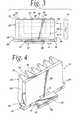
- FIG. 4is a perspective view of the heat sink of FIGS. 1-3, again showing the tower with one serpentine fin removed;
- FIGS. 5-7are somewhat diagrammatic top views of alternate embodiments of heat sinks embodying the present invention.
- a heat sink 10is provided for cooling an electronic component 12 , such as for example an integrated circuit, a CPU chip, a large scale chip package, or a very large scale chip package, having a surface 14 that rejects heat.
- the heat sink devicetransfers heat from the surface 14 of the electronic component 12 to a cooling airflow A provided by a fan 16 , which in the illustrated embodiment is mounted above the heat sink device 10 to direct an impingement airflow substantially perpendicular to the surface 14 .
- the heat sink device 10includes a base 20 including a substantially planar heat receiving surface 22 that overlays the heat rejecting surface 14 to receive heat therefrom.
- the heat receiving surface 22is preferably substantially the same size/area as the heat rejecting surface 14 of the electronic component 12 . It should be understood that for purposes of illustration the surfaces 14 and 22 are shown slightly spaced from each other, but in practice the surfaces will be abutted against each other or have a thermal transmitter, such a thermal gel, sandwiched between them.
- the heat sink 10further includes a heat conducting tower 24 extending from a side of the base member 20 opposite from the heat receiving surface 22 to receive heat therefrom.
- the towerincludes a pair of spaced, oppositely facing fin mount surfaces 26 , with the spacing between the fin mount surfaces 26 defining a width W of the tower 24 .
- each of the fin mount surfaces 26is planar, with the plane of each surface lying within 25° of perpendicular to the heat receiving surface 22 .
- each of the fin mount surfaces 26has an area larger than the area of the heat receiving surface 22 . Further, again as seen in FIGS.
- the fin mount surfaces 26extend past the heat receiving surface 22 in a direction, shown by arrow C, parallel to the heat receiving surface 22 and the fin mount surfaces 26 .
- the heat receiving surface 22be larger than the width W of the tower 24 in a direction parallel to the width W of the tower 24 .
- the base 20includes a pair of spaced shoulders 28 extending outward from the tower 24 for engagement with a suitable mount structure (not shown) for connecting the heat sink 10 to additional system components, such as for example, the fan 16 or a circuit board on which the electronic component 12 is mounted.
- the heat sink 10further includes a pair of serpentine fins 30 (one of the fins 30 is removed in FIGS. 2-4 for purposes of illustration) to transfer heat from the tower 24 to the airflow from the fan 16 .
- Each serpentine fin 30is formed from a folded strip of heat conducting material 32 including a plurality of peaks 34 and valleys 36 connected by sidewalls 38 , as best seen in FIGS. 2 and 4.
- any suitable heat conductive sheet materialsuch as for example aluminum or copper, can be used for the material 32 .
- the valleys 36 of one of the serpentine fins 30are bonded to one of the fin mount surfaces 26
- the valleys 36 of the other serpentine fin 30are bonded to the other fin mount surface 26 .
- the base 20preferably includes downwardly angled surfaces 39 that underlie the fins 30 opposite the heat receiving surface 22 so as to allow the airflow to escape from the fins 30 past the base 20 .
- the peaks 34 and the valleys 36lie in planes, shown schematically by dash lines 40 , that are substantially perpendicular to the heat receiving surface 22 so as to be parallel to the impingement airflow A.
- the serpentine fins 30may be bonded to the fin mount surfaces 26 so that the peaks 34 and valleys 36 extend at other angles.
- the peaks and valleysmay extend substantially parallel to the heat receiving surface, as shown by the phantom lines 42 in FIG. 3, so as to receive an airflow B from a fan 16 (shown in phantom in FIG. 3) that directs the airflow B substantially parallel to the heat rejecting surface 14 and the heat receiving surface 22 .
- the base 20 and the tower 24are a unitary piece of suitable heat conducting material, such as copper or aluminum.
- the base and towerare a unitary piece of CDA 101 copper.
- some embodimentsmay include one or more heat pipes that * are embedded in the tower 24 and/or the base 20 .
- FIG. 3One possible example is shown diagrammatically in FIG. 3 wherein a U-shaped heat pipe, shown by phantom line 44 is provided in the tower 24 and a straight heat pipe, shown by phantom line 46 , is embedded in the base 20 .
- the tower 24can be formed from one or more heat pipes 48 ( 3 shown in FIG. 5) that extends upward from the base 20 , with each of the heat pipes 48 including sidewalls 50 that form at least part of each of the fin mount surfaces 26 .
- the heat sink 10may include a heat pipe 52 (shown diagrammatically by dashed lines in FIG. 1) defined by a vapor chamber 54 enclosed within the base 20 and the tower 24 and having a suitable two-phase fluid, such as water, sealed with the chamber 54 , with the base 20 acting as an evaporator of the heat pipe 52 and the tower 24 acting as a condenser of the heat pipe 52 .
- a heat pipe 52shown diagrammatically by dashed lines in FIG. 1
- a suitable two-phase fluidsuch as water
- stacks 56 of serpentine fins 30can be mounted on the fin mount surfaces 26 , with the serpentine fins 30 in each stack 56 having their respects peaks 34 and valleys 36 bonded to planar separator plates 58 sandwiched between the adjacent fins 30 of the stack 56 .
- This constructionoffers a possible advantage because the fin density the number can be increased with a decrease in the fin height of each serpentine fin 30 .
- FIG. 7Yet another alternate embodiment of the heat sink 10 is shown in FIG. 7, wherein the heat sink 10 includes multiple towers 24 and multiple fins 30 sandwiched between the towers 24 .
- the serpentine fins 30may be plain fins as shown by the fin 30 on the left side of FIG. 1, or may include any suitable surface enhancement on the sidewalls 38 , such as for example, louvers, slits, or embossments, all of which are intended to be shown schematically by the lines 60 on the right side fin 30 in FIG. 1 .
- any suitable surface enhancement on the sidewalls 38such as for example, louvers, slits, or embossments, all of which are intended to be shown schematically by the lines 60 on the right side fin 30 in FIG. 1 .
- the particular details of the serpentine fins 30such as the fin height, fin pitch, fin material, and surface enhancement, will be highly be dependent upon the requirements of each particular application.
- each of the fin mount surfaces 26has an angle of inclination a with respect to a line perpendicular to the heat rejecting surface 14 and the heat receiving surface 22 .
- this angle of inclinationis no greater than 25°.
- the angle of inclinationis 5°. This angle of inclination allows the width W of the tower 24 to taper as the tower 24 extends away from the base 20 so as to somewhat correspond to the reduction in heat conduction required as heat is transmitted up the tower 24 .
- the heat sink 10can transfer the heat from the heat rejecting surface 14 primarily in a direction perpendicular thereto, rather than spreading the heat primarily parallel to the surface 14 . This allows for the base 20 to be eliminated from areas that do not overlie the surface 14 , thereby allowing for airflow past the heat sink 10 over these areas. Further, the tower 24 and its surfaces 26 allow for the use of at least two serpentine fins 30 to reject heat to the airflow from the fan 16 .
Landscapes
- Engineering & Computer Science (AREA)
- Physics & Mathematics (AREA)
- Thermal Sciences (AREA)
- Mechanical Engineering (AREA)
- General Engineering & Computer Science (AREA)
- Sustainable Development (AREA)
- Life Sciences & Earth Sciences (AREA)
- Condensed Matter Physics & Semiconductors (AREA)
- General Physics & Mathematics (AREA)
- Computer Hardware Design (AREA)
- Microelectronics & Electronic Packaging (AREA)
- Power Engineering (AREA)
- Cooling Or The Like Of Electrical Apparatus (AREA)
- Cooling Or The Like Of Semiconductors Or Solid State Devices (AREA)
Abstract
Description
Claims (24)
Priority Applications (1)
| Application Number | Priority Date | Filing Date | Title |
|---|---|---|---|
| US10/259,311US6830097B2 (en) | 2002-09-27 | 2002-09-27 | Combination tower and serpentine fin heat sink device |
Applications Claiming Priority (1)
| Application Number | Priority Date | Filing Date | Title |
|---|---|---|---|
| US10/259,311US6830097B2 (en) | 2002-09-27 | 2002-09-27 | Combination tower and serpentine fin heat sink device |
Publications (2)
| Publication Number | Publication Date |
|---|---|
| US20040060690A1 US20040060690A1 (en) | 2004-04-01 |
| US6830097B2true US6830097B2 (en) | 2004-12-14 |
Family
ID=32029481
Family Applications (1)
| Application Number | Title | Priority Date | Filing Date |
|---|---|---|---|
| US10/259,311Expired - Fee RelatedUS6830097B2 (en) | 2002-09-27 | 2002-09-27 | Combination tower and serpentine fin heat sink device |
Country Status (1)
| Country | Link |
|---|---|
| US (1) | US6830097B2 (en) |
Cited By (15)
| Publication number | Priority date | Publication date | Assignee | Title |
|---|---|---|---|---|
| US20040233636A1 (en)* | 2002-11-20 | 2004-11-25 | International Business Machines Corporation | Apparatus employing heat sink |
| US20040240180A1 (en)* | 2002-11-20 | 2004-12-02 | International Business Machines Corporation | Apparatus employing heat sink |
| US20050274490A1 (en)* | 2001-06-05 | 2005-12-15 | Larson Ralph I | Heatsink assembly and method of manufacturing the same |
| US20060011324A1 (en)* | 2004-07-13 | 2006-01-19 | Rogers C J | Wound, louvered fin heat sink device |
| US20060250776A1 (en)* | 2005-05-05 | 2006-11-09 | Abul-Haj Roxanne E | Heatsink method and apparatus |
| US20070091565A1 (en)* | 2005-10-25 | 2007-04-26 | Malone Christopher G | Impingement cooling of components in an electronic system |
| US20070147006A1 (en)* | 2005-12-27 | 2007-06-28 | Xue-Wen Peng | Heat dissipation device |
| US20070204972A1 (en)* | 2006-03-01 | 2007-09-06 | Sensis Corporation | Method and apparatus for dissipating heat |
| DE102006011528A1 (en)* | 2006-03-10 | 2007-09-13 | GÜNTHER, Ingrid | Heat pipe for cooling electronic component e.g. CPU, of e.g. personal computer, has working fluid container with working fluid for changing heat transfer phase and with upper and lower boundaries as cover and evaporator plate, respectively |
| RU2332818C1 (en)* | 2007-02-01 | 2008-08-27 | Общество с ограниченной ответственностью "Теркон КТТ" | Cooling device for electronic elements |
| USD613258S1 (en)* | 2009-05-15 | 2010-04-06 | Koninklije Philips Electronics N.V. | Heatsink |
| USD690039S1 (en) | 2011-08-12 | 2013-09-17 | Starlights, Inc. | Light fixture using modular accessories |
| US8979353B2 (en) | 2011-08-11 | 2015-03-17 | Starlights, Inc. | Light fixture having modular accessories and method of forming same |
| US20150090435A1 (en)* | 2013-09-29 | 2015-04-02 | Huawei Technologies Co., Ltd. | Support plateheat dissipation apparatus |
| US20230057918A1 (en)* | 2020-01-19 | 2023-02-23 | Raytheon Technologies Corporation | Aircraft Heat Exchanger Finned Plate Manufacture |
Families Citing this family (3)
| Publication number | Priority date | Publication date | Assignee | Title |
|---|---|---|---|---|
| TWM266686U (en)* | 2004-03-17 | 2005-06-01 | Chia Cherne Industry Co Ltd | Novel structure of bendable assembly shaving type heat sink |
| US20070246193A1 (en)* | 2006-04-20 | 2007-10-25 | Bhatti Mohinder S | Orientation insensitive thermosiphon of v-configuration |
| RU2437140C1 (en)* | 2010-12-13 | 2011-12-20 | Российская Федерация, от имени которой выступает Государственная корпорация по атомной энергии "Росатом" - Госкорпорация "Росатом" | Passive cooling system of radioactive elements in detachable module |
Citations (53)
| Publication number | Priority date | Publication date | Assignee | Title |
|---|---|---|---|---|
| US2680009A (en) | 1953-02-25 | 1954-06-01 | Rca Corp | Cooling unit |
| US2745895A (en) | 1951-06-09 | 1956-05-15 | Ernest J Lideen | Vacuum tube shield and heat radiator |
| US2917286A (en) | 1956-11-13 | 1959-12-15 | Siemens Edison Swan Ltd | Electronic equipment |
| US3023264A (en) | 1959-05-18 | 1962-02-27 | Cool Fin Electronics Corp | Heat-dissipating shield |
| US3180404A (en) | 1959-12-02 | 1965-04-27 | United Aircraft Prod | Cooling electronic heat producing elements and the like |
| US3185756A (en) | 1960-05-02 | 1965-05-25 | Cool Fin Electronics Corp | Heat-dissipating tube shield |
| US3187812A (en) | 1963-02-11 | 1965-06-08 | Staver Co | Heat dissipator for electronic circuitry |
| US3260787A (en) | 1962-12-20 | 1966-07-12 | Birtcher Corp | Transistor heat dissipators |
| US3542124A (en) | 1968-08-08 | 1970-11-24 | Garrett Corp | Heat exchanger |
| US4605058A (en) | 1985-04-01 | 1986-08-12 | The Staver Company, Inc. | Heat dissipating retainer for electronic package |
| US4753290A (en) | 1986-07-18 | 1988-06-28 | Unisys Corporation | Reduced-stress heat sink device |
| US4884631A (en) | 1988-03-17 | 1989-12-05 | California Institute Of Technology | Forced air heat sink apparatus |
| US4941530A (en) | 1989-01-13 | 1990-07-17 | Sundstrand Corporation | Enhanced air fin cooling arrangement for a hermetically sealed modular electronic cold plate utilizing reflux cooling |
| US4944344A (en) | 1988-10-31 | 1990-07-31 | Sundstrand Corporation | Hermetically sealed modular electronic cold plate utilizing reflux cooling |
| JPH03108747A (en)* | 1989-09-22 | 1991-05-08 | Furukawa Electric Co Ltd:The | Heat pipe type radiator |
| US5107922A (en) | 1991-03-01 | 1992-04-28 | Long Manufacturing Ltd. | Optimized offset strip fin for use in contact heat exchangers |
| US5195576A (en) | 1990-02-28 | 1993-03-23 | Hitachi, Ltd. | Lsi cooling apparatus and computer cooling apparatus |
| US5251101A (en) | 1992-11-05 | 1993-10-05 | Liu Te Chang | Dissipating structure for central processing unit chip |
| US5299632A (en) | 1993-02-19 | 1994-04-05 | Lee Lien Jung | Fin device for an integrated circuit |
| US5375655A (en) | 1993-03-31 | 1994-12-27 | Lee; Yong N. | Heat sink apparatus |
| US5421402A (en) | 1994-11-22 | 1995-06-06 | Lin; Chuen-Sheng | Heat sink apparatus |
| US5490558A (en) | 1992-04-13 | 1996-02-13 | Actronics Kabushiki Kaisha | L-type heat sink |
| US5494098A (en) | 1994-06-17 | 1996-02-27 | Wakefield Engineering, Inc. | Fan driven heat sink |
| US5597034A (en) | 1994-07-01 | 1997-01-28 | Digital Equipment Corporation | High performance fan heatsink assembly |
| US5727622A (en) | 1994-03-04 | 1998-03-17 | Elisra Gan Ltd. | Heat radiating element |
| US5791406A (en) | 1994-08-02 | 1998-08-11 | Hoogovens Aluminium Profiltechnik, Gmbh | Cooling device for electrical or electronic components having a base plate and cooling elements and method for manufacturing the same |
| US5794685A (en) | 1996-12-17 | 1998-08-18 | Hewlett-Packard Company | Heat sink device having radial heat and airflow paths |
| US5892655A (en) | 1997-06-27 | 1999-04-06 | Sun Microsystems, Inc. | Hard disk drive heat sink |
| US5894882A (en) | 1993-02-19 | 1999-04-20 | Fujitsu Limited | Heat sink structure for cooling a substrate and an electronic apparatus having such a heat sink structure |
| US5975194A (en) | 1996-02-01 | 1999-11-02 | Hewlett Packard Company | Fan assisted heat sink device |
| US6009937A (en) | 1995-12-20 | 2000-01-04 | Hoogovens Aluminium Profiltechnik Gmbh | Cooling device for electrical or electronic components having a base plate and cooling elements and method for manufacturing the same |
| US6015008A (en) | 1997-07-14 | 2000-01-18 | Mitsubishi Electric Home Appliance Co., Ltd. | Heat radiating plate |
| US6018459A (en) | 1997-11-17 | 2000-01-25 | Cray Research, Inc. | Porous metal heat sink |
| US6109341A (en) | 1998-04-30 | 2000-08-29 | Sanyo Denki Co., Ltd. | Electronic component cooling apparatus including elongated heat sink |
| US6135200A (en) | 1998-03-11 | 2000-10-24 | Denso Corporation | Heat generating element cooling unit with louvers |
| US6157539A (en) | 1999-08-13 | 2000-12-05 | Agilent Technologies | Cooling apparatus for electronic devices |
| US6196300B1 (en) | 1997-07-31 | 2001-03-06 | Maurizio Checchetti | Heat sink |
| EP1081760A2 (en) | 1999-08-30 | 2001-03-07 | Molex Incorporated | Heat sink assembly |
| US6199624B1 (en) | 1999-04-30 | 2001-03-13 | Molex Incorporated | Folded fin heat sink and a heat exchanger employing the heat sink |
| US6223813B1 (en) | 1996-01-11 | 2001-05-01 | International Business Machines Corporation | Ultra high-density, high-performance heat sink |
| US6311766B1 (en) | 2000-10-06 | 2001-11-06 | Foxconn Precision Components Co., Ltd. | Heat sink assembly |
| US6315033B1 (en) | 2000-05-22 | 2001-11-13 | Jia Hao Li | Heat dissipating conduit |
| US6324061B1 (en) | 1998-04-09 | 2001-11-27 | Yamato Corporation | Heat sink |
| US6327145B1 (en) | 2000-09-01 | 2001-12-04 | Intel Corporation | Heat sink with integrated fluid circulation pump |
| US6330908B1 (en) | 2000-03-15 | 2001-12-18 | Foxconn Precision Components Co., Ltd. | Heat sink |
| US6336499B1 (en) | 2001-05-31 | 2002-01-08 | Hong Tsai Liu | CPU heat sink mounting structure |
| US6336497B1 (en) | 2000-11-24 | 2002-01-08 | Ching-Bin Lin | Self-recirculated heat dissipating means for cooling central processing unit |
| US6360816B1 (en) | 1999-12-23 | 2002-03-26 | Agilent Technologies, Inc. | Cooling apparatus for electronic devices |
| US6367542B1 (en) | 2001-03-27 | 2002-04-09 | Foxconn Precision Components Co., Ltd. | Heat sink assembly with dual fans |
| US6371200B1 (en) | 1999-11-18 | 2002-04-16 | The United States Of America As Represented By The Secretary Of The Navy | Perforated heat sink |
| US6386275B1 (en) | 2001-08-16 | 2002-05-14 | Chaun-Choung Technology Corp. | Surrounding type fin-retaining structure of heat radiator |
| US6386274B1 (en) | 2001-06-28 | 2002-05-14 | Foxconn Precision Components Co., Ltd. | Heat sink assembly |
| US6404637B2 (en) | 2000-02-14 | 2002-06-11 | Special Product Company | Concentrical slot telecommunications equipment enclosure |
- 2002
- 2002-09-27USUS10/259,311patent/US6830097B2/ennot_activeExpired - Fee Related
Patent Citations (55)
| Publication number | Priority date | Publication date | Assignee | Title |
|---|---|---|---|---|
| US2745895A (en) | 1951-06-09 | 1956-05-15 | Ernest J Lideen | Vacuum tube shield and heat radiator |
| US2680009A (en) | 1953-02-25 | 1954-06-01 | Rca Corp | Cooling unit |
| US2917286A (en) | 1956-11-13 | 1959-12-15 | Siemens Edison Swan Ltd | Electronic equipment |
| US3023264A (en) | 1959-05-18 | 1962-02-27 | Cool Fin Electronics Corp | Heat-dissipating shield |
| US3180404A (en) | 1959-12-02 | 1965-04-27 | United Aircraft Prod | Cooling electronic heat producing elements and the like |
| US3185756A (en) | 1960-05-02 | 1965-05-25 | Cool Fin Electronics Corp | Heat-dissipating tube shield |
| US3260787A (en) | 1962-12-20 | 1966-07-12 | Birtcher Corp | Transistor heat dissipators |
| US3187812A (en) | 1963-02-11 | 1965-06-08 | Staver Co | Heat dissipator for electronic circuitry |
| US3542124A (en) | 1968-08-08 | 1970-11-24 | Garrett Corp | Heat exchanger |
| US4605058A (en) | 1985-04-01 | 1986-08-12 | The Staver Company, Inc. | Heat dissipating retainer for electronic package |
| US4753290A (en) | 1986-07-18 | 1988-06-28 | Unisys Corporation | Reduced-stress heat sink device |
| US4884631A (en) | 1988-03-17 | 1989-12-05 | California Institute Of Technology | Forced air heat sink apparatus |
| US4944344A (en) | 1988-10-31 | 1990-07-31 | Sundstrand Corporation | Hermetically sealed modular electronic cold plate utilizing reflux cooling |
| US4941530A (en) | 1989-01-13 | 1990-07-17 | Sundstrand Corporation | Enhanced air fin cooling arrangement for a hermetically sealed modular electronic cold plate utilizing reflux cooling |
| JPH03108747A (en)* | 1989-09-22 | 1991-05-08 | Furukawa Electric Co Ltd:The | Heat pipe type radiator |
| US5195576A (en) | 1990-02-28 | 1993-03-23 | Hitachi, Ltd. | Lsi cooling apparatus and computer cooling apparatus |
| US5107922A (en) | 1991-03-01 | 1992-04-28 | Long Manufacturing Ltd. | Optimized offset strip fin for use in contact heat exchangers |
| US5490558A (en) | 1992-04-13 | 1996-02-13 | Actronics Kabushiki Kaisha | L-type heat sink |
| US5251101A (en) | 1992-11-05 | 1993-10-05 | Liu Te Chang | Dissipating structure for central processing unit chip |
| US5299632A (en) | 1993-02-19 | 1994-04-05 | Lee Lien Jung | Fin device for an integrated circuit |
| US5894882A (en) | 1993-02-19 | 1999-04-20 | Fujitsu Limited | Heat sink structure for cooling a substrate and an electronic apparatus having such a heat sink structure |
| US5375655A (en) | 1993-03-31 | 1994-12-27 | Lee; Yong N. | Heat sink apparatus |
| US5653285A (en) | 1993-03-31 | 1997-08-05 | Lee; Yong N. | Heat sink apparatus |
| US5518071A (en) | 1993-03-31 | 1996-05-21 | Lee; Yong N. | Heat sink apparatus |
| US5727622A (en) | 1994-03-04 | 1998-03-17 | Elisra Gan Ltd. | Heat radiating element |
| US5494098A (en) | 1994-06-17 | 1996-02-27 | Wakefield Engineering, Inc. | Fan driven heat sink |
| US5597034A (en) | 1994-07-01 | 1997-01-28 | Digital Equipment Corporation | High performance fan heatsink assembly |
| US5791406A (en) | 1994-08-02 | 1998-08-11 | Hoogovens Aluminium Profiltechnik, Gmbh | Cooling device for electrical or electronic components having a base plate and cooling elements and method for manufacturing the same |
| US5421402A (en) | 1994-11-22 | 1995-06-06 | Lin; Chuen-Sheng | Heat sink apparatus |
| US6009937A (en) | 1995-12-20 | 2000-01-04 | Hoogovens Aluminium Profiltechnik Gmbh | Cooling device for electrical or electronic components having a base plate and cooling elements and method for manufacturing the same |
| US6223813B1 (en) | 1996-01-11 | 2001-05-01 | International Business Machines Corporation | Ultra high-density, high-performance heat sink |
| US5975194A (en) | 1996-02-01 | 1999-11-02 | Hewlett Packard Company | Fan assisted heat sink device |
| US5794685A (en) | 1996-12-17 | 1998-08-18 | Hewlett-Packard Company | Heat sink device having radial heat and airflow paths |
| US5892655A (en) | 1997-06-27 | 1999-04-06 | Sun Microsystems, Inc. | Hard disk drive heat sink |
| US6015008A (en) | 1997-07-14 | 2000-01-18 | Mitsubishi Electric Home Appliance Co., Ltd. | Heat radiating plate |
| US6196300B1 (en) | 1997-07-31 | 2001-03-06 | Maurizio Checchetti | Heat sink |
| US6018459A (en) | 1997-11-17 | 2000-01-25 | Cray Research, Inc. | Porous metal heat sink |
| US6135200A (en) | 1998-03-11 | 2000-10-24 | Denso Corporation | Heat generating element cooling unit with louvers |
| US6324061B1 (en) | 1998-04-09 | 2001-11-27 | Yamato Corporation | Heat sink |
| US6109341A (en) | 1998-04-30 | 2000-08-29 | Sanyo Denki Co., Ltd. | Electronic component cooling apparatus including elongated heat sink |
| US6199624B1 (en) | 1999-04-30 | 2001-03-13 | Molex Incorporated | Folded fin heat sink and a heat exchanger employing the heat sink |
| US6157539A (en) | 1999-08-13 | 2000-12-05 | Agilent Technologies | Cooling apparatus for electronic devices |
| EP1081760A2 (en) | 1999-08-30 | 2001-03-07 | Molex Incorporated | Heat sink assembly |
| US6371200B1 (en) | 1999-11-18 | 2002-04-16 | The United States Of America As Represented By The Secretary Of The Navy | Perforated heat sink |
| US6360816B1 (en) | 1999-12-23 | 2002-03-26 | Agilent Technologies, Inc. | Cooling apparatus for electronic devices |
| US6404637B2 (en) | 2000-02-14 | 2002-06-11 | Special Product Company | Concentrical slot telecommunications equipment enclosure |
| US6330908B1 (en) | 2000-03-15 | 2001-12-18 | Foxconn Precision Components Co., Ltd. | Heat sink |
| US6315033B1 (en) | 2000-05-22 | 2001-11-13 | Jia Hao Li | Heat dissipating conduit |
| US6327145B1 (en) | 2000-09-01 | 2001-12-04 | Intel Corporation | Heat sink with integrated fluid circulation pump |
| US6311766B1 (en) | 2000-10-06 | 2001-11-06 | Foxconn Precision Components Co., Ltd. | Heat sink assembly |
| US6336497B1 (en) | 2000-11-24 | 2002-01-08 | Ching-Bin Lin | Self-recirculated heat dissipating means for cooling central processing unit |
| US6367542B1 (en) | 2001-03-27 | 2002-04-09 | Foxconn Precision Components Co., Ltd. | Heat sink assembly with dual fans |
| US6336499B1 (en) | 2001-05-31 | 2002-01-08 | Hong Tsai Liu | CPU heat sink mounting structure |
| US6386274B1 (en) | 2001-06-28 | 2002-05-14 | Foxconn Precision Components Co., Ltd. | Heat sink assembly |
| US6386275B1 (en) | 2001-08-16 | 2002-05-14 | Chaun-Choung Technology Corp. | Surrounding type fin-retaining structure of heat radiator |
Cited By (22)
| Publication number | Priority date | Publication date | Assignee | Title |
|---|---|---|---|---|
| US7284596B2 (en)* | 2001-06-05 | 2007-10-23 | Heat Technology, Inc. | Heatsink assembly and method of manufacturing the same |
| US20050274490A1 (en)* | 2001-06-05 | 2005-12-15 | Larson Ralph I | Heatsink assembly and method of manufacturing the same |
| US20040240180A1 (en)* | 2002-11-20 | 2004-12-02 | International Business Machines Corporation | Apparatus employing heat sink |
| US20040233636A1 (en)* | 2002-11-20 | 2004-11-25 | International Business Machines Corporation | Apparatus employing heat sink |
| US20060011324A1 (en)* | 2004-07-13 | 2006-01-19 | Rogers C J | Wound, louvered fin heat sink device |
| US20060250776A1 (en)* | 2005-05-05 | 2006-11-09 | Abul-Haj Roxanne E | Heatsink method and apparatus |
| US7751192B2 (en) | 2005-05-05 | 2010-07-06 | Sensys Medical, Inc. | Heatsink method and apparatus |
| US7593230B2 (en)* | 2005-05-05 | 2009-09-22 | Sensys Medical, Inc. | Apparatus for absorbing and dissipating excess heat generated by a system |
| US20080030957A1 (en)* | 2005-05-05 | 2008-02-07 | Abul-Haj Roxanne E | Heatsink method and apparatus |
| US20070091565A1 (en)* | 2005-10-25 | 2007-04-26 | Malone Christopher G | Impingement cooling of components in an electronic system |
| US7548421B2 (en) | 2005-10-25 | 2009-06-16 | Hewlett-Packard Development Company, L.P. | Impingement cooling of components in an electronic system |
| US7509996B2 (en) | 2005-12-27 | 2009-03-31 | Fu Zhun Precision Industry (Shen Zhen) Co., Ltd. | Heat dissipation device |
| US20070147006A1 (en)* | 2005-12-27 | 2007-06-28 | Xue-Wen Peng | Heat dissipation device |
| US20070204972A1 (en)* | 2006-03-01 | 2007-09-06 | Sensis Corporation | Method and apparatus for dissipating heat |
| DE102006011528A1 (en)* | 2006-03-10 | 2007-09-13 | GÜNTHER, Ingrid | Heat pipe for cooling electronic component e.g. CPU, of e.g. personal computer, has working fluid container with working fluid for changing heat transfer phase and with upper and lower boundaries as cover and evaporator plate, respectively |
| RU2332818C1 (en)* | 2007-02-01 | 2008-08-27 | Общество с ограниченной ответственностью "Теркон КТТ" | Cooling device for electronic elements |
| USD613258S1 (en)* | 2009-05-15 | 2010-04-06 | Koninklije Philips Electronics N.V. | Heatsink |
| US8979353B2 (en) | 2011-08-11 | 2015-03-17 | Starlights, Inc. | Light fixture having modular accessories and method of forming same |
| USD690039S1 (en) | 2011-08-12 | 2013-09-17 | Starlights, Inc. | Light fixture using modular accessories |
| US20150090435A1 (en)* | 2013-09-29 | 2015-04-02 | Huawei Technologies Co., Ltd. | Support plateheat dissipation apparatus |
| US11604035B2 (en)* | 2013-09-29 | 2023-03-14 | Huawei Technologies Co., Ltd. | Support plateheat dissipation apparatus |
| US20230057918A1 (en)* | 2020-01-19 | 2023-02-23 | Raytheon Technologies Corporation | Aircraft Heat Exchanger Finned Plate Manufacture |
Also Published As
| Publication number | Publication date |
|---|---|
| US20040060690A1 (en) | 2004-04-01 |
Similar Documents
| Publication | Publication Date | Title |
|---|---|---|
| US6830097B2 (en) | Combination tower and serpentine fin heat sink device | |
| US6026895A (en) | Flexible foil finned heatsink structure and method of making same | |
| US7440279B2 (en) | Heat dissipation device | |
| US6590770B1 (en) | Serpentine, slit fin heat sink device | |
| US6922340B2 (en) | Stack up assembly | |
| US7250675B2 (en) | Method and apparatus for forming stacked die and substrate structures for increased packing density | |
| US7443677B1 (en) | Heat dissipation device | |
| US7779897B2 (en) | Heat dissipation device with heat pipes | |
| US8220527B2 (en) | Heat dissipation device with heat pipe | |
| US7529089B2 (en) | Heat-dissipating device connected in series to water-cooling circulation system | |
| EP0035390B1 (en) | A semiconductor integrated circuit device with an improved heat sink | |
| US20080128118A1 (en) | Heat dissipation device with a heat pipe | |
| US20020015288A1 (en) | High performance thermal/mechanical interface for fixed-gap references for high heat flux and power semiconductor applications | |
| EP0285779A2 (en) | Improved cooling system for semiconductor modules | |
| KR20060035765A (en) | Thermal diffusion device | |
| US20090145588A1 (en) | Heat dissipation device with heat pipe | |
| US20070169919A1 (en) | Heat pipe type heat dissipation device | |
| US7093648B1 (en) | Heat pipe cooling device and method for manufacturing the same | |
| CN116114060A (en) | Heat sink configuration for multichip modules | |
| US20080289799A1 (en) | Heat dissipation device with a heat pipe | |
| US20050063159A1 (en) | Heat-dissipating fin module | |
| US20060032617A1 (en) | Heat sink electronic components | |
| US7726385B2 (en) | Heat dissipation interface for semiconductor chip structures | |
| US20080142192A1 (en) | Heat dissipation device with a heat pipe | |
| US12262514B2 (en) | Heat sinks with beyond-board fins |
Legal Events
| Date | Code | Title | Description |
|---|---|---|---|
| AS | Assignment | Owner name:MODINE MANUFACTURING COMPANY, WISCONSIN Free format text:ASSIGNMENT OF ASSIGNORS INTEREST;ASSIGNORS:WATTELET, JONATHAN P.;GARNER, SCOTT D.;REEL/FRAME:015285/0913 Effective date:20021204 | |
| FEPP | Fee payment procedure | Free format text:PAYOR NUMBER ASSIGNED (ORIGINAL EVENT CODE: ASPN); ENTITY STATUS OF PATENT OWNER: LARGE ENTITY | |
| REMI | Maintenance fee reminder mailed | ||
| AS | Assignment | Owner name:NATIONAL PENN BANK, PENNSYLVANIA Free format text:SECURITY AGREEMENT;ASSIGNORS:THERMAL CORP.;FSBO VENTURE ACQUISITIONS, INC.;REEL/FRAME:021398/0300 Effective date:20080430 Owner name:NATIONAL PENN BANK,PENNSYLVANIA Free format text:SECURITY AGREEMENT;ASSIGNORS:THERMAL CORP.;FSBO VENTURE ACQUISITIONS, INC.;REEL/FRAME:021398/0300 Effective date:20080430 | |
| LAPS | Lapse for failure to pay maintenance fees | ||
| STCH | Information on status: patent discontinuation | Free format text:PATENT EXPIRED DUE TO NONPAYMENT OF MAINTENANCE FEES UNDER 37 CFR 1.362 | |
| FP | Lapsed due to failure to pay maintenance fee | Effective date:20081214 | |
| AS | Assignment | Owner name:SOVEREIGN BANK, PENNSYLVANIA Free format text:SECURITY AGREEMENT;ASSIGNORS:THERMACORE, INC.;THERMAL CORP.;REEL/FRAME:026039/0865 Effective date:20101230 | |
| AS | Assignment | Owner name:THERMACORE, INC. F/K/A FSBO VENTURE ACQUISITIONS, Free format text:RELEASE OF SECURITY INTEREST RECORDED AT REEL/FRAME 021398/0300;ASSIGNOR:NATIONAL PENN BANK;REEL/FRAME:040508/0620 Effective date:20101230 Owner name:THERMAL CORP., NEW HAMPSHIRE Free format text:RELEASE OF SECURITY INTEREST RECORDED AT REEL/FRAME 026039/0865;ASSIGNOR:SANTANDER BANK, N.A. F/K/A SOVEREIGN BANK;REEL/FRAME:040508/0649 Effective date:20161013 Owner name:THERMACORE, INC., PENNSYLVANIA Free format text:RELEASE OF SECURITY INTEREST RECORDED AT REEL/FRAME 026039/0865;ASSIGNOR:SANTANDER BANK, N.A. F/K/A SOVEREIGN BANK;REEL/FRAME:040508/0649 Effective date:20161013 Owner name:THERMAL CORP., NEW HAMPSHIRE Free format text:RELEASE OF SECURITY INTEREST RECORDED AT REEL/FRAME 021398/0300;ASSIGNOR:NATIONAL PENN BANK;REEL/FRAME:040508/0620 Effective date:20101230 |