US6829819B1 - Method of forming a magnetoresistive device - Google Patents
Method of forming a magnetoresistive deviceDownload PDFInfo
- Publication number
- US6829819B1 US6829819B1US10/013,431US1343101AUS6829819B1US 6829819 B1US6829819 B1US 6829819B1US 1343101 AUS1343101 AUS 1343101AUS 6829819 B1US6829819 B1US 6829819B1
- Authority
- US
- United States
- Prior art keywords
- pole
- pedestal
- abs
- tapered
- width
- Prior art date
- Legal status (The legal status is an assumption and is not a legal conclusion. Google has not performed a legal analysis and makes no representation as to the accuracy of the status listed.)
- Expired - Fee Related, expires
Links
Images


Classifications
- G—PHYSICS
- G11—INFORMATION STORAGE
- G11B—INFORMATION STORAGE BASED ON RELATIVE MOVEMENT BETWEEN RECORD CARRIER AND TRANSDUCER
- G11B5/00—Recording by magnetisation or demagnetisation of a record carrier; Reproducing by magnetic means; Record carriers therefor
- G11B5/127—Structure or manufacture of heads, e.g. inductive
- G11B5/33—Structure or manufacture of flux-sensitive heads, i.e. for reproduction only; Combination of such heads with means for recording or erasing only
- G11B5/39—Structure or manufacture of flux-sensitive heads, i.e. for reproduction only; Combination of such heads with means for recording or erasing only using magneto-resistive devices or effects
- G11B5/3903—Structure or manufacture of flux-sensitive heads, i.e. for reproduction only; Combination of such heads with means for recording or erasing only using magneto-resistive devices or effects using magnetic thin film layers or their effects, the films being part of integrated structures
- G11B5/3906—Details related to the use of magnetic thin film layers or to their effects
- G11B5/3912—Arrangements in which the active read-out elements are transducing in association with active magnetic shields, e.g. magnetically coupled shields
- G—PHYSICS
- G11—INFORMATION STORAGE
- G11B—INFORMATION STORAGE BASED ON RELATIVE MOVEMENT BETWEEN RECORD CARRIER AND TRANSDUCER
- G11B5/00—Recording by magnetisation or demagnetisation of a record carrier; Reproducing by magnetic means; Record carriers therefor
- G11B5/127—Structure or manufacture of heads, e.g. inductive
- G11B5/31—Structure or manufacture of heads, e.g. inductive using thin films
- G11B5/3109—Details
- G11B5/3116—Shaping of layers, poles or gaps for improving the form of the electrical signal transduced, e.g. for shielding, contour effect, equalizing, side flux fringing, cross talk reduction between heads or between heads and information tracks
- G—PHYSICS
- G11—INFORMATION STORAGE
- G11B—INFORMATION STORAGE BASED ON RELATIVE MOVEMENT BETWEEN RECORD CARRIER AND TRANSDUCER
- G11B5/00—Recording by magnetisation or demagnetisation of a record carrier; Reproducing by magnetic means; Record carriers therefor
- G11B5/127—Structure or manufacture of heads, e.g. inductive
- G11B5/31—Structure or manufacture of heads, e.g. inductive using thin films
- G11B5/3109—Details
- G11B5/313—Disposition of layers
- G—PHYSICS
- G11—INFORMATION STORAGE
- G11B—INFORMATION STORAGE BASED ON RELATIVE MOVEMENT BETWEEN RECORD CARRIER AND TRANSDUCER
- G11B5/00—Recording by magnetisation or demagnetisation of a record carrier; Reproducing by magnetic means; Record carriers therefor
- G11B5/127—Structure or manufacture of heads, e.g. inductive
- G11B5/31—Structure or manufacture of heads, e.g. inductive using thin films
- G11B5/3163—Fabrication methods or processes specially adapted for a particular head structure, e.g. using base layers for electroplating, using functional layers for masking, using energy or particle beams for shaping the structure or modifying the properties of the basic layers
- G—PHYSICS
- G11—INFORMATION STORAGE
- G11B—INFORMATION STORAGE BASED ON RELATIVE MOVEMENT BETWEEN RECORD CARRIER AND TRANSDUCER
- G11B5/00—Recording by magnetisation or demagnetisation of a record carrier; Reproducing by magnetic means; Record carriers therefor
- G11B5/02—Recording, reproducing, or erasing methods; Read, write or erase circuits therefor
- G11B5/09—Digital recording
- G—PHYSICS
- G11—INFORMATION STORAGE
- G11B—INFORMATION STORAGE BASED ON RELATIVE MOVEMENT BETWEEN RECORD CARRIER AND TRANSDUCER
- G11B5/00—Recording by magnetisation or demagnetisation of a record carrier; Reproducing by magnetic means; Record carriers therefor
- G11B5/127—Structure or manufacture of heads, e.g. inductive
- G11B5/31—Structure or manufacture of heads, e.g. inductive using thin films
- G11B5/3109—Details
- G11B5/313—Disposition of layers
- G11B5/3143—Disposition of layers including additional layers for improving the electromagnetic transducing properties of the basic structure, e.g. for flux coupling, guiding or shielding
- G11B5/3146—Disposition of layers including additional layers for improving the electromagnetic transducing properties of the basic structure, e.g. for flux coupling, guiding or shielding magnetic layers
- G—PHYSICS
- G11—INFORMATION STORAGE
- G11B—INFORMATION STORAGE BASED ON RELATIVE MOVEMENT BETWEEN RECORD CARRIER AND TRANSDUCER
- G11B5/00—Recording by magnetisation or demagnetisation of a record carrier; Reproducing by magnetic means; Record carriers therefor
- G11B5/127—Structure or manufacture of heads, e.g. inductive
- G11B5/33—Structure or manufacture of flux-sensitive heads, i.e. for reproduction only; Combination of such heads with means for recording or erasing only
- G11B5/39—Structure or manufacture of flux-sensitive heads, i.e. for reproduction only; Combination of such heads with means for recording or erasing only using magneto-resistive devices or effects
- G11B5/3903—Structure or manufacture of flux-sensitive heads, i.e. for reproduction only; Combination of such heads with means for recording or erasing only using magneto-resistive devices or effects using magnetic thin film layers or their effects, the films being part of integrated structures
- G11B5/3967—Composite structural arrangements of transducers, e.g. inductive write and magnetoresistive read
- Y—GENERAL TAGGING OF NEW TECHNOLOGICAL DEVELOPMENTS; GENERAL TAGGING OF CROSS-SECTIONAL TECHNOLOGIES SPANNING OVER SEVERAL SECTIONS OF THE IPC; TECHNICAL SUBJECTS COVERED BY FORMER USPC CROSS-REFERENCE ART COLLECTIONS [XRACs] AND DIGESTS
- Y10—TECHNICAL SUBJECTS COVERED BY FORMER USPC
- Y10T—TECHNICAL SUBJECTS COVERED BY FORMER US CLASSIFICATION
- Y10T29/00—Metal working
- Y10T29/49—Method of mechanical manufacture
- Y10T29/49002—Electrical device making
- Y10T29/4902—Electromagnet, transformer or inductor
- Y10T29/49021—Magnetic recording reproducing transducer [e.g., tape head, core, etc.]
- Y10T29/49032—Fabricating head structure or component thereof
- Y10T29/49036—Fabricating head structure or component thereof including measuring or testing
- Y10T29/49039—Fabricating head structure or component thereof including measuring or testing with dual gap materials
- Y—GENERAL TAGGING OF NEW TECHNOLOGICAL DEVELOPMENTS; GENERAL TAGGING OF CROSS-SECTIONAL TECHNOLOGIES SPANNING OVER SEVERAL SECTIONS OF THE IPC; TECHNICAL SUBJECTS COVERED BY FORMER USPC CROSS-REFERENCE ART COLLECTIONS [XRACs] AND DIGESTS
- Y10—TECHNICAL SUBJECTS COVERED BY FORMER USPC
- Y10T—TECHNICAL SUBJECTS COVERED BY FORMER US CLASSIFICATION
- Y10T29/00—Metal working
- Y10T29/49—Method of mechanical manufacture
- Y10T29/49002—Electrical device making
- Y10T29/4902—Electromagnet, transformer or inductor
- Y10T29/49021—Magnetic recording reproducing transducer [e.g., tape head, core, etc.]
- Y10T29/49032—Fabricating head structure or component thereof
- Y10T29/49036—Fabricating head structure or component thereof including measuring or testing
- Y10T29/49041—Fabricating head structure or component thereof including measuring or testing with significant slider/housing shaping or treating
- Y—GENERAL TAGGING OF NEW TECHNOLOGICAL DEVELOPMENTS; GENERAL TAGGING OF CROSS-SECTIONAL TECHNOLOGIES SPANNING OVER SEVERAL SECTIONS OF THE IPC; TECHNICAL SUBJECTS COVERED BY FORMER USPC CROSS-REFERENCE ART COLLECTIONS [XRACs] AND DIGESTS
- Y10—TECHNICAL SUBJECTS COVERED BY FORMER USPC
- Y10T—TECHNICAL SUBJECTS COVERED BY FORMER US CLASSIFICATION
- Y10T29/00—Metal working
- Y10T29/49—Method of mechanical manufacture
- Y10T29/49002—Electrical device making
- Y10T29/4902—Electromagnet, transformer or inductor
- Y10T29/49021—Magnetic recording reproducing transducer [e.g., tape head, core, etc.]
- Y10T29/49032—Fabricating head structure or component thereof
- Y10T29/49048—Machining magnetic material [e.g., grinding, etching, polishing]
- Y10T29/4905—Employing workholding means
- Y—GENERAL TAGGING OF NEW TECHNOLOGICAL DEVELOPMENTS; GENERAL TAGGING OF CROSS-SECTIONAL TECHNOLOGIES SPANNING OVER SEVERAL SECTIONS OF THE IPC; TECHNICAL SUBJECTS COVERED BY FORMER USPC CROSS-REFERENCE ART COLLECTIONS [XRACs] AND DIGESTS
- Y10—TECHNICAL SUBJECTS COVERED BY FORMER USPC
- Y10T—TECHNICAL SUBJECTS COVERED BY FORMER US CLASSIFICATION
- Y10T29/00—Metal working
- Y10T29/49—Method of mechanical manufacture
- Y10T29/49002—Electrical device making
- Y10T29/4902—Electromagnet, transformer or inductor
- Y10T29/49071—Electromagnet, transformer or inductor by winding or coiling
- Y—GENERAL TAGGING OF NEW TECHNOLOGICAL DEVELOPMENTS; GENERAL TAGGING OF CROSS-SECTIONAL TECHNOLOGIES SPANNING OVER SEVERAL SECTIONS OF THE IPC; TECHNICAL SUBJECTS COVERED BY FORMER USPC CROSS-REFERENCE ART COLLECTIONS [XRACs] AND DIGESTS
- Y10—TECHNICAL SUBJECTS COVERED BY FORMER USPC
- Y10T—TECHNICAL SUBJECTS COVERED BY FORMER US CLASSIFICATION
- Y10T29/00—Metal working
- Y10T29/49—Method of mechanical manufacture
- Y10T29/49002—Electrical device making
- Y10T29/4902—Electromagnet, transformer or inductor
- Y10T29/49073—Electromagnet, transformer or inductor by assembling coil and core
Definitions
- This inventionrelates generally to magnetic disk data storage systems, and more particularly to magnetic write transducers and methods for making same, and most specifically to high density magnetic write transducers and methods of making same.
- Magnetic disk drivesare used to store and retrieve data for digital electronic apparatuses such as computers.
- a magnetic disk data storage systems 10 of the prior artincludes a sealed enclosure 12 , a disk drive motor 14 , a magnetic disk 16 , supported for rotation by a drive spindle S 1 of motor 14 , an actuator 18 and an arm 20 attached to an actuator spindle S 2 of actuator 18 .
- a suspension 22is coupled at one end to the arm 20 , and at its other end to a read/write head or transducer 24 .
- the transducer 24(which will be described in greater detail with reference to FIG. 2A) typically includes an inductive write element with a sensor read element.
- FIG. 2Adepicts a magnetic read/write head 24 including a substrate 25 above which a read element 26 and a write element 28 are disposed. Edges of the read element 26 and write element 28 also define an air bearing surface ABS, in a plane 29 , which can be aligned to face the surface of the magnetic disk 16 (see FIGS. 1 A and 1 B).
- the read element 26includes a first shield 30 , an intermediate layer 32 , which functions as a second shield, and a read sensor 34 that is located within a dielectric medium 35 between the first shield 30 and the second shield 32 .
- the most common type of read sensor 34 used in the read/write head 24is the magnetoresistive (AMR or GMR) sensor which is used to detect magnetic field signals from a magnetic medium through changing resistance in the read sensor.
- AMRmagnetoresistive
- the write element 28is typically an inductive write element which includes the intermediate layer 32 , which functions as a first pole, and a second pole 38 disposed above the first pole 32 .
- the first pole 32 and the second pole 38are attached to each other by a backgap portion 40 , with these three elements collectively forming a yoke 41 .
- Above and attached to the first pole 32 at a first pole tip portion 43is a first pole pedestal 42 abutting the ABS.
- a second pole pedestal 44is attached to the second pole 38 at a second pole tip portion 45 and aligned with the first pole pedestal 42 .
- This area including the first and second poles 42 and 44 near the ABSis sometimes referred to as the yoke tip region 46 .
- a write gap 36is formed between the first and second pole pedestals 42 and 44 in the yoke tip region 46 .
- the write gap 36is filled with a non-magnetic material.
- This non-magnetic materialcan be either integral with (as is shown here) or separate from a first insulation layer 47 that lies below the second pole 38 and extends from the yoke tip region 46 to the backgap portion 40 .
- Also included in write element 28is a conductive coil 48 , formed of multiple winds 49 , that is positioned within a dielectric medium 50 that lies above the first insulation layer 47 . As is well known to those skilled in the art, these elements operate to magnetically write data on a magnetic medium such as a magnetic disk 16 .
- an inductive write headsuch as that shown in FIGS. 2A-2C operates by passing a writing current through the conductive coil layer 48 . Because of the magnetic properties of the yoke 41 , a magnetic flux is induced in the yoke 41 by write currents that are passed through the coil layer 48 .
- the write gap 36allows the magnetic flux to fringe out from the yoke 41 (thus forming a fringing gap field) and to cross a magnetic recording medium that is placed near the ABS.
- a critical parameter of a magnetic write elementis a trackwidth of the write element, which determines a magnetic write width (MWW), and therefore drives the recording track density. For example, a narrower trackwidth can result in a narrower MWW and a higher magnetic recording density.
- the trackwidthis affected by geometries in the yoke tip portion 46 (see FIG. 2A) at the ABS. These geometries can be better understood with reference to FIG. 2B, a view taken along line 2 B— 2 B of FIG. 2 A.
- the first and second poles 32 , 38can have different widths W 1 , W 2 respectively in the yoke tip portion 46 (see FIG. 2 A).
- the trackwidth of the write element 28is defined by the width Wp of the second pole pedestal 44 .
- the width Wp of the pole pedestalstypically is substantially uniform.
- the gap field of the write elementalso can be affected by the throat height TH, which is measured from the ABS to the zero throat ZT, as shown in FIG. 2 A.
- accurate definition of the both trackwidth and throat heightis critical during the fabrication of the write element.
- the control of trackwidth and throat heightcan be limited with typical fabrication processes, such as masking and plating at the wafer level.
- the trackwidth sigma ⁇ twcan be limited to a minimum of 0.07 microns.
- These problemsare further aggravated with increasing topography over which the trackwidth-defining element is formed. Such topography is created by the various heights of other elements that have been formed before the trackwidth-defining element is formed.
- Greater trackwidth controlcan be attempted using other processes such as focused ion beam (FIB) milling, however such processes can be expensive.
- the trackwidthcan be defined by the first pole width W 1 .
- such processescan also be expensive, complex, and result in lower production yields.
- An additional disadvantage of some current write element configurationsis a secondary pulse phenomenon that can degrade recording performance.
- an intended primary pulseis generated to record a single bit of data.
- an unintended second pulsemay be produced just after the primary pulse.
- linear densityincreases, in other words, as one attempts to write bits closer together and primary pulses follow one another more closely, this second pulse effect may distort the waveforms of the primary pulses.
- Such distortions generated by the prior art write elements shown in FIGS. 2A-2C when operated at high linear densitiesmakes them unsuitable for high density magnetic recording applications.
- wire elementthat is effective for applications having data densities on the order of 40 Gbits/in 2 with a trackwidth of less than about 1 micron and exhibiting substantially no secondary pulse phenomenon. Further, it is desired to achieve these qualities inexpensively, easily, and while maximizing throughput.
- the present inventionprovides a magnetic write element and method for making the same that provides high writing performance in high density applications, and can be inexpensively and quickly fabricated with high yield.
- a write elementis provided which has a very small trackwidth, good trackwidth and throat height definition control, and substantially no secondary pulse.
- a magnetoresistive device for recording data on a magnetic mediaincludes a first pole having a first pole first surface lying substantially in a plane and a second pole having a second pole first surface lying substantially in the plane. Also, the device includes a tapered second pole pedestal disposed between the first pole and the second pole and magnetically connected to the second pole.
- the tapered second pole pedestalhas a second pole pedestal first surface lying substantially in the plane, and has a second pole pedestal width measured substantially parallel to the plane, wherein the second pole pedestal width, of at least a portion of said second pole pedestal that is proximate the plane, increases with increasing distance away from the plane.
- the devicecan further include a first pole pedestal between the first pole and the second pole pedestal and magnetically connected to the first pole.
- the first pole pedestalcan have a first pole pedestal first surface lying substantially in the plane, and hae a first pole pedestal width measured substantially parallel to the plane, wherein the first pole pedestal width, of at least a portion of the first pole pedestal that is proximate the plane, increases with increasing distance away from the plane.
- a method of forming a magnetoresistive deviceincludes providing a first pole and forming a first tapered pole pedestal having a first pedestal ABS portion that includes an ABS plane.
- the first pedestal ABS portionhas a first end and a second end, wherein a width of the tapered pole pedestal increases from the first end to the second end.
- the methodalso includes forming a write gap layer formed of non-magnetic, electrically insulating material between the first pole and the first tapered pole pedestal. Also, a second pole that is magnetically connected to said first tapered pole pedestal is formed.
- the methodadditionally includes exposing a first pedestal ABS surface, of the first tapered pole pedestal, within the ABS plane by lapping the first pedestal ABS portion beginning at the first end, wherein the width of the first tapered pole pedestal at the first pedestal ABS surface is substantially equal to a desired width.
- the methodcan further include providing a read sensor having a first end and including the ABS plane.
- a sensor ABS surface within said ABS planeis also exposed, thereby defining a stripe height of the read sensor.
- FIG. 1Ais a partial cross-sectional front elevation view of a magnetic data storage system
- FIG. 1Bis a top plan view taken along line 1 B— 1 B of FIG. 1A;
- FIG. 2Ais a cross-sectional side view of a prior art read/write head of the magnetic disk drive assembly of FIGS. 1A and 1B;
- FIG. 2Bis an ABS view taken along line 2 B— 2 B of FIG. 2A;
- FIG. 2Cis a plan view taken along line 2 C— 2 C of FIG. 2A;
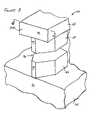
- FIG. 3is a perspective view of a pole tip portion of a write element, according to an embodiment of the present invention.
- FIG. 4Ais a plan view of the pole tip portion of the write element, taken along line 4 — 4 of FIG. 3, according to an embodiment of the present invention
- FIG. 4Bis a plan view of a wafer-level write element, according to an embodiment of the present invention.
- FIG. 5is a plan view of a second pole pedestal and read sensor of a read/write head, according to an embodiment of the present invention
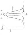
- FIG. 6depicts and representative graph of the magnetic writing field strength according to an embodiment of the present invention as compared to the prior art
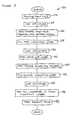
- FIG. 7is a process diagram of a method for forming a write element, according to an embodiment of the present invention.
- FIG. 8is a process diagram of a method for forming a write element, according to another embodiment of the present invention.
- FIG. 3is a perspective view of a pole tip portion of a write element 60 , according to an embodiment of the present invention.
- the write element 60includes a first pole 62 and a second pole 64 , formed of a magnetic material, similar to those of the prior art.
- a first pole pedestal 66is also formed of magnetic material and is magnetically connected to the first pole 62 .
- a second pole pedestal 68 formed of magnetic materialis magnetically connected to the second pole 64 .
- the first pole 62includes a first pole first surface 70 which forms a portion of the air bearing surface ABS.
- a first pole pedestal first surface 72 , and a second pole pedestal first surface 74are also included in the air bearing surface ABS, along with a second pole first surface 76 .
- the first pole pedestal 66 and second pole pedestal 68are disposed between the first pole 62 and the second pole 64 and further define a write gap 71 therebetween.
- the write gap 71can be filled with non-magnetic, electrically insulating material (not shown).
- the first and second pole pedestals 66 , 68have a tapered shape that can be better understood with reference to FIG. 4 and the related discussion below.
- FIG. 4Ais a plan view of the write element 60 taken along line 4 A— 4 A of FIG. 3 .
- a second pole pedestal width W P2Pincreases with increasing distance D from the ABS. Therefore, the second pole pedestal width WP P2P at the ABS is the most narrow portion of the second pole pedestal 68 .
- the shape of the second pole pedestal 68 away from ABSis also important since it affects the throat height as well as the trackwidth definition.
- the second pole pedestal 68 of the present inventionutilizes a greater volume of magnetic material. This greater volume of magnetic material significantly reduces the magnetic saturation at the interface between the second pole 64 and second pole pedestal 68 , thereby substantially eliminating second pulse effects. As previously noted, removing second pulse effects can lead to increased writing performance which may be necessary for achieving high density magnetic recording.
- a physical trackwidth of the write element 60can be defined with much smaller dimensions that can be typically obtained with processes and techniques of the prior art.
- the second pole pedestal ABS width W P2P ABScan be defined with very small values to define the physical trackwidth of the write element 60 .
- FIG. 4Bshows a plan view of the wafer-level write element 84 .
- the first pole 62 , second pole 64 , first pole pedestal 66 , and second pole pedestal 68each extends beyond an ABS plane 79 within which an air bearing surface ABS is desired to be exposed.
- This air bearing surface ABSis exposed by cutting the wafer that includes the write element 84 along one or more planes that are substantially parallel to the ABS plane 79 , to thereby form one or more individual slider bars. The cut surface of such a slider bar is then lapped until the air bearing surface ABS is exposed.
- those portions of the first pole 62 , second pole 64 , first pole pedestal 66 , and second pole pedestal 68 that extend beyond the ABS plane 79 at the wafer level,are removed during this lapping process.
- the read sensor 86may also include a portion that extends beyond the ABS plane 79 and that is removed during the above-described lapping.
- the stripe height SH of the read sensor 86can be accurately defined in this way.
- the stripe heightcan be defined to within a stripe height tolerance ⁇ SH of no more than about 5 ⁇ ins. Because of this lapping accuracy, the throat height TH of the second pole pedestal 86 , defined as the distance between the air bearing surface ABS and the zero throat ZT, can also be accurately defined during the same lapping process.
- the second pole pedestal ABS width W P2P ABScan also be more accurately defined than in the prior art. Further, because of the accuracy of this width definition, smaller such widths can be defined than in the prior art.
- the first pole pedestal 66can be similarly formed with similarly accurate definition of an ABS width.
- the first pole pedestal 66is not tapered, and alternatively may have a substantially uniform width with increasing distance away from the air bearing surface ABS.
- FIG. 5depicts a plan view of the second pole pedestal 68 and the read sensor 86 .
- the dashed linesdepict the structures at the wafer level prior to lapping, while the solid lines depict the structures after the air bearing surface ABS has been exposed through lapping.
- the ABS width W P2P ABScan be determined as a function of the throat height TH.
- the offset height OSHdefined as the difference between the throat height TH and the read sensor 86 stripe height SH
- the ABS width W P2P ABScan further be determined as a function of the stripe height SH.
- the second pole pedestal ABS width W P2P ABScan be defined by the following equation:
- the throat height THand therefore the ABS width W P2P ABS are also accurately defined.
- These improvementsprovide a trackwidth that is both narrower and better defined than previously achievable by the prior art, leading to higher write performance.
- the effect on write performance of this more accurately defined and narrower ABS width W P2P ABScan be seen with reference to the graph in FIG. 6 .
- the graphdepicts gap field profiles in the direction of the trackwidth for both an embodiment of the present invention and for a typical design of the prior art.
- the magnetic write width MWW of the present inventioncan be less than that of the prior art, and further include narrower erase bands.
- the prior arttypically can have a magnetic write width MWW on the order of about 1.25 ⁇ m
- the write element of the present inventionincorporating a tapered first pole pedestal and a tapered second pole pedestal, can obtain a magnetic write width on the order of about 0.2 ⁇ m to about 1 ⁇ m.
- the erase bandwidth EB 1 of the present inventioncan be limited to within the range of about 0.05 ⁇ m to about 0.1 ⁇ m by the inclusion of tapered first and second pole pedestals.
- significantly higher data densitiescan be obtained in recording of data on a magnetic media. For example, densities on the order of 40 Gbits/in 2 can be achieved.
- FIG. 7depicts a process diagram for a method 100 for forming a write element according to an embodiment of the present invention.
- a first poleis provided.
- the first polecan be formed of a magnetic material, such as permalloy.
- the first polecan be provided above a substrate, or alternatively above a read element.
- the first pole of operation 102otherwise can be provided as a second shield of a read element.
- Operation 104includes forming a tapered first pole pedestal that is magnetically connected to the first pole provide in operation 102 .
- the first pole pedestalcan be formed of a magnetic material, similar to or the same as the material of the first pole of operation 102 .
- a backgap portioncan also be formed above and magnetically connected to the first pole of operation 102 , distal the tapered first pole pedestal.
- a first insulation layeris formed in operation 106 above the first pole of operation 102 , and between the tapered first pole pedestal and the backgap portion. Importantly, the first insulation layer of operation 106 leaves at least a portion of the tapered first pole pedestal and the backgap portion exposed. In operation 108 , a write gap layer is formed above the exposed surface of the tapered first pole pedestal.
- a tapered second pole pedestalis formed in operation 110 above and aligned with the tapered first pole pedestal of operation 104 .
- the write gap layer of operation 108is disposed between the tapered first pole pedestal and the tapered second pole pedestal.
- the first insulation layer of operation 106can be integral with the write gap layer of operation 108 , and can be formed in essentially the same operation.
- a second insulation layeris formed in operation 112 , between the tapered second pole pedestal and the back gap portion of operation 104 . Importantly, a portion of the tapered second pole pedestal and a portion of the backgap portion remains exposed.
- a coil embedded in a third insulation layeris formed above the second insulation layer.
- a second poleis formed above the third insulation layer and magnetically connected to both the tapered second pole pedestal of operation 110 and the backgap portion of operation 104 .
- the tapered first pole pedestal, tapered second pole pedestal, and second poleeach can be formed using known methods, such as by masking and plating magnetic materials, followed by mask lift off.
- the first, second, and third insulation layers of operations 106 , 112 , and 114can be formed of any suitable non-magnetic, electrically insulating material, such as alumina. In some alternative embodiments, one or more of these insulation layers can be formed of cured photoresistive material.
- FIG. 8depicts a process diagram for a method 120 for forming a write element, according to another embodiment of the present invention.
- a first pole formed of magnetic materialis provided in operation 122 .
- the first pole of operation 122is chemically-mechanically polished (CMP).
- CMPchemically-mechanically polished
- the CMP operationforms a substantially planar upper surface of the first pole of operation 122 .
- a tapered first pole pedestalis formed in operation 126 . More particularly, the tapered first pole pedestal is formed of magnetic material and is magnetically connected to the first pole of operation 122 .
- a backgap portionis formed in operation 126 that is magnetically connected to the first pole distal the tapered first pole pedestal.
- a first insulation layeris formed in operation 128 between the tapered first pole pedestal and the backgap portion of operation 126
- the first insulation layer of operation 128 , and the first pole pedestal and backgap portion of operation 126are chemically-mechanically polished.
- the first insulation layercovers the tapered first pole pedestal and backgap portion in operation 128
- the CMP operation of operation 130exposes an upper surface of the tapered first pole pedestal and an upper surface of a back gap portion.
- the first insulation layer formation in operation 128leaves the tapered first pole pedestal and the back gap portion exposed before the CMP of operation 130 .
- the CMP of operation 130renders an upper surface of the tapered first pole pedestal, an upper surface of the back gap portion, and an upper surface of the first insulation layer each substantially planar, and substantially co-planar with each other.
- a write gap layeris formed above the exposed tapered first pole pedestal and exposed backgap portion, and above the first insulation of operation 128 .
- the write gap layercan be formed of any suitable non-magnetic, electrically insulating material, such as alumina.
- a tapered second pole pedestal formed of magnetic materialis formed in operation 134 .
- a second insulation layeris formed in operation 136 above the write gap layer 132 .
- the tapered second pole pedestal of operation 134 and the second insulation layer of operation 136are chemically-mechanically polished.
- the second insulation layercovers the tapered second pole pedestal in operation 136 .
- the operation 138 CMPthen exposes the tapered second pole pedestal.
- the second insulation layers formed in operation 136leaving the tapered second pole pedestal exposed without facilitation by the CMP of operation 138 . In either case, the CMP of operation 138 renders an upper surface of the tapered second pole pedestal and an upper surface of the second insulation layer substantially planar, and substantially co-planar with each other.
- a coil embedded in a third insulation layeris formed above the second insulation layer of operation 136 .
- a second pole formed of magnetic materialis formed in operation 142 .
- the second pole of operation 142is magnetically connected to the substantially planar upper surface of the tapered second pole pedestal 134 and to the backgap portion 126 .
- the first polecan be provided above a substrate or above a read element, and can be incorporated as a second shield of a read element.
- the formation of the tapered first pole pedestal and the tapered second pole pedestalcan be substantially similar, including processes known to those skilled in the art, such as masking and plating followed by mask lift off.
- the second polecan be formed in operation 142 with similar methods and of similar material as that for forming the first and second tapered pole pedestals and the first pole, for example permalloy.
- the first, second, and third insulation layerscan be formed of any suitable non magnetic, electrically insulating material such as alumina, or cured photoresistive material.
- first and secondas applied to the poles, pedestals, and insulation layers and other aspects of the present invention are used for convenience of explanation, and do not necessarily limit the order in which the elements are formed, nor the particular combinations of elements. Also, only a single pedestal might be included, which may be magnetically connected to either pole, or two pedestals might be included, with only one being tapered. Therefore, for example, a write element of the present invention could include a first pole as well as a second pole that also operates as one of two shields of a read element. Further, a tapered pole pedestal may be-magnetically connected to the-second-pole and separated from the first pole by a write gap. Additionally, a second, non-tapered pole pedestal (i.e., a second pole pedestal) may be connected to said first pole, and separated from the tapered pole pedestal (i.e., the first pole pedestal) by a write gap.
- the write element trackwidthBy defining the write element trackwidth by the trackwidth of a tapered pole pedestal, very small trackwidths can be defined. For example, trackwidths of less than 1 micron, including trackwidths of about 0.2 microns, can be achieved. In addition, these trackwidths can be tightly controlled, to a tolerance of ⁇ TW of no more than about 5 ⁇ ins. With such closely controlled and small trackwidths, the write elements of the present invention can effectively operate in applications requiring recording densities on the order of about 40 Gbit/in 2 . Also, the tapered shape of the pole pedestal substantially eliminates the second pulse phenomenon, thereby improving the recording performance of the write element. Further, these benefits can be realized with methods of the present invention with minimal cost, time, and complexity.
- the present inventionprovides structures and methods for providing a magnetoresistive write element that has more precisely defined and smaller trackwidth, and therefore exhibits increased write performance over previous write elements.
- the inventionhas been described herein in terms of several preferred embodiments. Other embodiments of the invention, including alternatives, modifications, permutations and equivalents of the embodiments described herein, will be apparent to those skilled in the art from consideration of the specification, study of the drawings, and practice of the invention.
- the above described write elementcan be incorporated with a read element to provide a read/write head, or further incorporated with other components of a disk drive system.
- the embodiments and preferred features described aboveshould be considered exemplary, with the invention being defined by the appended claims, which therefore include all such alternatives, modifications, permutations and equivalents as fall within the true spirit and scope of the present invention.
Landscapes
- Engineering & Computer Science (AREA)
- Manufacturing & Machinery (AREA)
- Magnetic Heads (AREA)
Abstract
Description
Claims (8)
Priority Applications (2)
| Application Number | Priority Date | Filing Date | Title |
|---|---|---|---|
| US10/013,431US6829819B1 (en) | 1999-05-03 | 2001-12-11 | Method of forming a magnetoresistive device |
| US10/976,504US6944938B1 (en) | 1999-05-03 | 2004-10-29 | Method of forming a magnetoresistive device |
Applications Claiming Priority (2)
| Application Number | Priority Date | Filing Date | Title |
|---|---|---|---|
| US30422499A | 1999-05-03 | 1999-05-03 | |
| US10/013,431US6829819B1 (en) | 1999-05-03 | 2001-12-11 | Method of forming a magnetoresistive device |
Related Parent Applications (1)
| Application Number | Title | Priority Date | Filing Date |
|---|---|---|---|
| US30422499ADivision | 1999-05-03 | 1999-05-03 |
Related Child Applications (1)
| Application Number | Title | Priority Date | Filing Date |
|---|---|---|---|
| US10/976,504DivisionUS6944938B1 (en) | 1999-05-03 | 2004-10-29 | Method of forming a magnetoresistive device |
Publications (1)
| Publication Number | Publication Date |
|---|---|
| US6829819B1true US6829819B1 (en) | 2004-12-14 |
Family
ID=33489163
Family Applications (1)
| Application Number | Title | Priority Date | Filing Date |
|---|---|---|---|
| US10/013,431Expired - Fee RelatedUS6829819B1 (en) | 1999-05-03 | 2001-12-11 | Method of forming a magnetoresistive device |
Country Status (1)
| Country | Link |
|---|---|
| US (1) | US6829819B1 (en) |
Cited By (142)
| Publication number | Priority date | Publication date | Assignee | Title |
|---|---|---|---|---|
| US20040268067A1 (en)* | 2003-06-26 | 2004-12-30 | Hitachi, Ltd. | Method and apparatus for backup and recovery system using storage based journaling |
| US20050015416A1 (en)* | 2003-07-16 | 2005-01-20 | Hitachi, Ltd. | Method and apparatus for data recovery using storage based journaling |
| US20050028022A1 (en)* | 2003-06-26 | 2005-02-03 | Hitachi, Ltd. | Method and apparatus for data recovery system using storage based journaling |
| US20050264932A1 (en)* | 2004-05-28 | 2005-12-01 | Hitachi Global Technologies Netherlands B.V. | Method and apparatus for providing a pole tip structure having a shape for preventing oversaturation of the pole tip structure |
| US7023658B1 (en)* | 2000-02-08 | 2006-04-04 | Western Digital (Fremont), Inc. | Submicron track-width pole-tips for electromagnetic transducers |
| US20060149792A1 (en)* | 2003-07-25 | 2006-07-06 | Hitachi, Ltd. | Method and apparatus for synchronizing applications for data recovery using storage based journaling |
| US7243256B2 (en) | 2003-03-20 | 2007-07-10 | Hitachi, Ltd. | External storage and data recovery method for external storage as well as program |
| US20070206323A1 (en)* | 2005-02-07 | 2007-09-06 | Samsung Electronics Co., Ltd. | Asymmetric type perpendicular magnetic recording head and method of manufacturing the same |
| US7725445B2 (en) | 2003-06-27 | 2010-05-25 | Hitachi, Ltd. | Data replication among storage systems |
| US8705205B1 (en) | 2011-06-27 | 2014-04-22 | Western Digital (Fremont), Llc | Magnetic recording head having a dual sidewall angle |
| US8792208B1 (en) | 2012-05-25 | 2014-07-29 | Western Digital (Fremont), Llc | Method for providing side shields having non-conformal regions for a magnetic recording transducer |
| US8830628B1 (en) | 2009-02-23 | 2014-09-09 | Western Digital (Fremont), Llc | Method and system for providing a perpendicular magnetic recording head |
| US8879207B1 (en) | 2011-12-20 | 2014-11-04 | Western Digital (Fremont), Llc | Method for providing a side shield for a magnetic recording transducer using an air bridge |
| US8883017B1 (en) | 2013-03-12 | 2014-11-11 | Western Digital (Fremont), Llc | Method and system for providing a read transducer having seamless interfaces |
| US8917581B1 (en) | 2013-12-18 | 2014-12-23 | Western Digital Technologies, Inc. | Self-anneal process for a near field transducer and chimney in a hard disk drive assembly |
| US8923102B1 (en) | 2013-07-16 | 2014-12-30 | Western Digital (Fremont), Llc | Optical grating coupling for interferometric waveguides in heat assisted magnetic recording heads |
| US8947985B1 (en) | 2013-07-16 | 2015-02-03 | Western Digital (Fremont), Llc | Heat assisted magnetic recording transducers having a recessed pole |
| US8953422B1 (en) | 2014-06-10 | 2015-02-10 | Western Digital (Fremont), Llc | Near field transducer using dielectric waveguide core with fine ridge feature |
| US8958272B1 (en) | 2014-06-10 | 2015-02-17 | Western Digital (Fremont), Llc | Interfering near field transducer for energy assisted magnetic recording |
| US8970988B1 (en) | 2013-12-31 | 2015-03-03 | Western Digital (Fremont), Llc | Electric gaps and method for making electric gaps for multiple sensor arrays |
| US8971160B1 (en) | 2013-12-19 | 2015-03-03 | Western Digital (Fremont), Llc | Near field transducer with high refractive index pin for heat assisted magnetic recording |
| US8976635B1 (en) | 2014-06-10 | 2015-03-10 | Western Digital (Fremont), Llc | Near field transducer driven by a transverse electric waveguide for energy assisted magnetic recording |
| US8982508B1 (en) | 2011-10-31 | 2015-03-17 | Western Digital (Fremont), Llc | Method for providing a side shield for a magnetic recording transducer |
| US8980109B1 (en) | 2012-12-11 | 2015-03-17 | Western Digital (Fremont), Llc | Method for providing a magnetic recording transducer using a combined main pole and side shield CMP for a wraparound shield scheme |
| US8984740B1 (en) | 2012-11-30 | 2015-03-24 | Western Digital (Fremont), Llc | Process for providing a magnetic recording transducer having a smooth magnetic seed layer |
| US8988812B1 (en) | 2013-11-27 | 2015-03-24 | Western Digital (Fremont), Llc | Multi-sensor array configuration for a two-dimensional magnetic recording (TDMR) operation |
| US8988825B1 (en) | 2014-02-28 | 2015-03-24 | Western Digital (Fremont, LLC | Method for fabricating a magnetic writer having half-side shields |
| US8993217B1 (en) | 2013-04-04 | 2015-03-31 | Western Digital (Fremont), Llc | Double exposure technique for high resolution disk imaging |
| US8995087B1 (en) | 2006-11-29 | 2015-03-31 | Western Digital (Fremont), Llc | Perpendicular magnetic recording write head having a wrap around shield |
| US8997832B1 (en) | 2010-11-23 | 2015-04-07 | Western Digital (Fremont), Llc | Method of fabricating micrometer scale components |
| US9001467B1 (en) | 2014-03-05 | 2015-04-07 | Western Digital (Fremont), Llc | Method for fabricating side shields in a magnetic writer |
| US9001628B1 (en) | 2013-12-16 | 2015-04-07 | Western Digital (Fremont), Llc | Assistant waveguides for evaluating main waveguide coupling efficiency and diode laser alignment tolerances for hard disk |
| US9007719B1 (en) | 2013-10-23 | 2015-04-14 | Western Digital (Fremont), Llc | Systems and methods for using double mask techniques to achieve very small features |
| US9007725B1 (en) | 2014-10-07 | 2015-04-14 | Western Digital (Fremont), Llc | Sensor with positive coupling between dual ferromagnetic free layer laminates |
| US9007879B1 (en) | 2014-06-10 | 2015-04-14 | Western Digital (Fremont), Llc | Interfering near field transducer having a wide metal bar feature for energy assisted magnetic recording |
| US9013836B1 (en) | 2013-04-02 | 2015-04-21 | Western Digital (Fremont), Llc | Method and system for providing an antiferromagnetically coupled return pole |
| US9042052B1 (en) | 2014-06-23 | 2015-05-26 | Western Digital (Fremont), Llc | Magnetic writer having a partially shunted coil |
| US9042057B1 (en) | 2013-01-09 | 2015-05-26 | Western Digital (Fremont), Llc | Methods for providing magnetic storage elements with high magneto-resistance using Heusler alloys |
| US9042208B1 (en) | 2013-03-11 | 2015-05-26 | Western Digital Technologies, Inc. | Disk drive measuring fly height by applying a bias voltage to an electrically insulated write component of a head |
| US9042058B1 (en) | 2013-10-17 | 2015-05-26 | Western Digital Technologies, Inc. | Shield designed for middle shields in a multiple sensor array |
| US9042051B2 (en) | 2013-08-15 | 2015-05-26 | Western Digital (Fremont), Llc | Gradient write gap for perpendicular magnetic recording writer |
| US9053735B1 (en) | 2014-06-20 | 2015-06-09 | Western Digital (Fremont), Llc | Method for fabricating a magnetic writer using a full-film metal planarization |
| US9064528B1 (en) | 2013-05-17 | 2015-06-23 | Western Digital Technologies, Inc. | Interferometric waveguide usable in shingled heat assisted magnetic recording in the absence of a near-field transducer |
| US9064527B1 (en) | 2013-04-12 | 2015-06-23 | Western Digital (Fremont), Llc | High order tapered waveguide for use in a heat assisted magnetic recording head |
| US9064507B1 (en) | 2009-07-31 | 2015-06-23 | Western Digital (Fremont), Llc | Magnetic etch-stop layer for magnetoresistive read heads |
| US9065043B1 (en) | 2012-06-29 | 2015-06-23 | Western Digital (Fremont), Llc | Tunnel magnetoresistance read head with narrow shield-to-shield spacing |
| US9070381B1 (en) | 2013-04-12 | 2015-06-30 | Western Digital (Fremont), Llc | Magnetic recording read transducer having a laminated free layer |
| US9082423B1 (en) | 2013-12-18 | 2015-07-14 | Western Digital (Fremont), Llc | Magnetic recording write transducer having an improved trailing surface profile |
| US9087534B1 (en) | 2011-12-20 | 2015-07-21 | Western Digital (Fremont), Llc | Method and system for providing a read transducer having soft and hard magnetic bias structures |
| US9087527B1 (en) | 2014-10-28 | 2015-07-21 | Western Digital (Fremont), Llc | Apparatus and method for middle shield connection in magnetic recording transducers |
| US9093639B2 (en) | 2012-02-21 | 2015-07-28 | Western Digital (Fremont), Llc | Methods for manufacturing a magnetoresistive structure utilizing heating and cooling |
| US9104107B1 (en) | 2013-04-03 | 2015-08-11 | Western Digital (Fremont), Llc | DUV photoresist process |
| US9111558B1 (en) | 2014-03-14 | 2015-08-18 | Western Digital (Fremont), Llc | System and method of diffractive focusing of light in a waveguide |
| US9111564B1 (en) | 2013-04-02 | 2015-08-18 | Western Digital (Fremont), Llc | Magnetic recording writer having a main pole with multiple flare angles |
| US9111550B1 (en) | 2014-12-04 | 2015-08-18 | Western Digital (Fremont), Llc | Write transducer having a magnetic buffer layer spaced between a side shield and a write pole by non-magnetic layers |
| US9123359B1 (en) | 2010-12-22 | 2015-09-01 | Western Digital (Fremont), Llc | Magnetic recording transducer with sputtered antiferromagnetic coupling trilayer between plated ferromagnetic shields and method of fabrication |
| US9123362B1 (en) | 2011-03-22 | 2015-09-01 | Western Digital (Fremont), Llc | Methods for assembling an electrically assisted magnetic recording (EAMR) head |
| US9123374B1 (en) | 2015-02-12 | 2015-09-01 | Western Digital (Fremont), Llc | Heat assisted magnetic recording writer having an integrated polarization rotation plate |
| US9123358B1 (en) | 2012-06-11 | 2015-09-01 | Western Digital (Fremont), Llc | Conformal high moment side shield seed layer for perpendicular magnetic recording writer |
| US9135930B1 (en) | 2014-03-06 | 2015-09-15 | Western Digital (Fremont), Llc | Method for fabricating a magnetic write pole using vacuum deposition |
| US9135937B1 (en) | 2014-05-09 | 2015-09-15 | Western Digital (Fremont), Llc | Current modulation on laser diode for energy assisted magnetic recording transducer |
| US9142233B1 (en) | 2014-02-28 | 2015-09-22 | Western Digital (Fremont), Llc | Heat assisted magnetic recording writer having a recessed pole |
| US9147408B1 (en) | 2013-12-19 | 2015-09-29 | Western Digital (Fremont), Llc | Heated AFM layer deposition and cooling process for TMR magnetic recording sensor with high pinning field |
| US9147404B1 (en) | 2015-03-31 | 2015-09-29 | Western Digital (Fremont), Llc | Method and system for providing a read transducer having a dual free layer |
| US9153255B1 (en) | 2014-03-05 | 2015-10-06 | Western Digital (Fremont), Llc | Method for fabricating a magnetic writer having an asymmetric gap and shields |
| US9183854B2 (en) | 2014-02-24 | 2015-11-10 | Western Digital (Fremont), Llc | Method to make interferometric taper waveguide for HAMR light delivery |
| US9190079B1 (en) | 2014-09-22 | 2015-11-17 | Western Digital (Fremont), Llc | Magnetic write pole having engineered radius of curvature and chisel angle profiles |
| US9190085B1 (en) | 2014-03-12 | 2015-11-17 | Western Digital (Fremont), Llc | Waveguide with reflective grating for localized energy intensity |
| US9194692B1 (en) | 2013-12-06 | 2015-11-24 | Western Digital (Fremont), Llc | Systems and methods for using white light interferometry to measure undercut of a bi-layer structure |
| US9202480B2 (en) | 2009-10-14 | 2015-12-01 | Western Digital (Fremont), LLC. | Double patterning hard mask for damascene perpendicular magnetic recording (PMR) writer |
| US9202493B1 (en) | 2014-02-28 | 2015-12-01 | Western Digital (Fremont), Llc | Method of making an ultra-sharp tip mode converter for a HAMR head |
| US9214169B1 (en) | 2014-06-20 | 2015-12-15 | Western Digital (Fremont), Llc | Magnetic recording read transducer having a laminated free layer |
| US9213322B1 (en) | 2012-08-16 | 2015-12-15 | Western Digital (Fremont), Llc | Methods for providing run to run process control using a dynamic tuner |
| US9214172B2 (en) | 2013-10-23 | 2015-12-15 | Western Digital (Fremont), Llc | Method of manufacturing a magnetic read head |
| US9214165B1 (en) | 2014-12-18 | 2015-12-15 | Western Digital (Fremont), Llc | Magnetic writer having a gradient in saturation magnetization of the shields |
| US9230565B1 (en) | 2014-06-24 | 2016-01-05 | Western Digital (Fremont), Llc | Magnetic shield for magnetic recording head |
| US9236560B1 (en) | 2014-12-08 | 2016-01-12 | Western Digital (Fremont), Llc | Spin transfer torque tunneling magnetoresistive device having a laminated free layer with perpendicular magnetic anisotropy |
| US9245543B1 (en) | 2010-06-25 | 2016-01-26 | Western Digital (Fremont), Llc | Method for providing an energy assisted magnetic recording head having a laser integrally mounted to the slider |
| US9245545B1 (en) | 2013-04-12 | 2016-01-26 | Wester Digital (Fremont), Llc | Short yoke length coils for magnetic heads in disk drives |
| US9245562B1 (en) | 2015-03-30 | 2016-01-26 | Western Digital (Fremont), Llc | Magnetic recording writer with a composite main pole |
| US9251813B1 (en) | 2009-04-19 | 2016-02-02 | Western Digital (Fremont), Llc | Method of making a magnetic recording head |
| US9263067B1 (en) | 2013-05-29 | 2016-02-16 | Western Digital (Fremont), Llc | Process for making PMR writer with constant side wall angle |
| US9263071B1 (en) | 2015-03-31 | 2016-02-16 | Western Digital (Fremont), Llc | Flat NFT for heat assisted magnetic recording |
| US9269382B1 (en) | 2012-06-29 | 2016-02-23 | Western Digital (Fremont), Llc | Method and system for providing a read transducer having improved pinning of the pinned layer at higher recording densities |
| US9275657B1 (en) | 2013-08-14 | 2016-03-01 | Western Digital (Fremont), Llc | Process for making PMR writer with non-conformal side gaps |
| US9280990B1 (en) | 2013-12-11 | 2016-03-08 | Western Digital (Fremont), Llc | Method for fabricating a magnetic writer using multiple etches |
| US9286919B1 (en) | 2014-12-17 | 2016-03-15 | Western Digital (Fremont), Llc | Magnetic writer having a dual side gap |
| US9287494B1 (en) | 2013-06-28 | 2016-03-15 | Western Digital (Fremont), Llc | Magnetic tunnel junction (MTJ) with a magnesium oxide tunnel barrier |
| US9305583B1 (en) | 2014-02-18 | 2016-04-05 | Western Digital (Fremont), Llc | Method for fabricating a magnetic writer using multiple etches of damascene materials |
| US9312064B1 (en) | 2015-03-02 | 2016-04-12 | Western Digital (Fremont), Llc | Method to fabricate a magnetic head including ion milling of read gap using dual layer hard mask |
| US9318130B1 (en) | 2013-07-02 | 2016-04-19 | Western Digital (Fremont), Llc | Method to fabricate tunneling magnetic recording heads with extended pinned layer |
| US9336814B1 (en) | 2013-03-12 | 2016-05-10 | Western Digital (Fremont), Llc | Inverse tapered waveguide for use in a heat assisted magnetic recording head |
| US9343087B1 (en) | 2014-12-21 | 2016-05-17 | Western Digital (Fremont), Llc | Method for fabricating a magnetic writer having half shields |
| US9343098B1 (en) | 2013-08-23 | 2016-05-17 | Western Digital (Fremont), Llc | Method for providing a heat assisted magnetic recording transducer having protective pads |
| US9343086B1 (en) | 2013-09-11 | 2016-05-17 | Western Digital (Fremont), Llc | Magnetic recording write transducer having an improved sidewall angle profile |
| US9349392B1 (en) | 2012-05-24 | 2016-05-24 | Western Digital (Fremont), Llc | Methods for improving adhesion on dielectric substrates |
| US9349394B1 (en) | 2013-10-18 | 2016-05-24 | Western Digital (Fremont), Llc | Method for fabricating a magnetic writer having a gradient side gap |
| US9361914B1 (en) | 2014-06-18 | 2016-06-07 | Western Digital (Fremont), Llc | Magnetic sensor with thin capping layer |
| US9361913B1 (en) | 2013-06-03 | 2016-06-07 | Western Digital (Fremont), Llc | Recording read heads with a multi-layer AFM layer methods and apparatuses |
| US9368134B1 (en) | 2010-12-16 | 2016-06-14 | Western Digital (Fremont), Llc | Method and system for providing an antiferromagnetically coupled writer |
| US9384765B1 (en) | 2015-09-24 | 2016-07-05 | Western Digital (Fremont), Llc | Method and system for providing a HAMR writer having improved optical efficiency |
| US9384763B1 (en) | 2015-03-26 | 2016-07-05 | Western Digital (Fremont), Llc | Dual free layer magnetic reader having a rear bias structure including a soft bias layer |
| US9396742B1 (en) | 2012-11-30 | 2016-07-19 | Western Digital (Fremont), Llc | Magnetoresistive sensor for a magnetic storage system read head, and fabrication method thereof |
| US9396743B1 (en) | 2014-02-28 | 2016-07-19 | Western Digital (Fremont), Llc | Systems and methods for controlling soft bias thickness for tunnel magnetoresistance readers |
| US9406331B1 (en) | 2013-06-17 | 2016-08-02 | Western Digital (Fremont), Llc | Method for making ultra-narrow read sensor and read transducer device resulting therefrom |
| US9424866B1 (en) | 2015-09-24 | 2016-08-23 | Western Digital (Fremont), Llc | Heat assisted magnetic recording write apparatus having a dielectric gap |
| US9431039B1 (en) | 2013-05-21 | 2016-08-30 | Western Digital (Fremont), Llc | Multiple sensor array usable in two-dimensional magnetic recording |
| US9431038B1 (en) | 2015-06-29 | 2016-08-30 | Western Digital (Fremont), Llc | Method for fabricating a magnetic write pole having an improved sidewall angle profile |
| US9431047B1 (en) | 2013-05-01 | 2016-08-30 | Western Digital (Fremont), Llc | Method for providing an improved AFM reader shield |
| US9431032B1 (en) | 2013-08-14 | 2016-08-30 | Western Digital (Fremont), Llc | Electrical connection arrangement for a multiple sensor array usable in two-dimensional magnetic recording |
| US9431031B1 (en) | 2015-03-24 | 2016-08-30 | Western Digital (Fremont), Llc | System and method for magnetic transducers having multiple sensors and AFC shields |
| US9437251B1 (en) | 2014-12-22 | 2016-09-06 | Western Digital (Fremont), Llc | Apparatus and method having TDMR reader to reader shunts |
| US9443541B1 (en) | 2015-03-24 | 2016-09-13 | Western Digital (Fremont), Llc | Magnetic writer having a gradient in saturation magnetization of the shields and return pole |
| US9441938B1 (en) | 2013-10-08 | 2016-09-13 | Western Digital (Fremont), Llc | Test structures for measuring near field transducer disc length |
| US9449621B1 (en) | 2015-03-26 | 2016-09-20 | Western Digital (Fremont), Llc | Dual free layer magnetic reader having a rear bias structure having a high aspect ratio |
| US9449625B1 (en) | 2014-12-24 | 2016-09-20 | Western Digital (Fremont), Llc | Heat assisted magnetic recording head having a plurality of diffusion barrier layers |
| US9472216B1 (en) | 2015-09-23 | 2016-10-18 | Western Digital (Fremont), Llc | Differential dual free layer magnetic reader |
| US9478236B1 (en) | 2012-09-28 | 2016-10-25 | Western Digital (Fremont), Llc | Perpendicular magnetic recording write head |
| US9484051B1 (en) | 2015-11-09 | 2016-11-01 | The Provost, Fellows, Foundation Scholars and the other members of Board, of the College of the Holy and Undivided Trinity of Queen Elizabeth near Dublin | Method and system for reducing undesirable reflections in a HAMR write apparatus |
| US9508365B1 (en) | 2015-06-24 | 2016-11-29 | Western Digital (Fremont), LLC. | Magnetic reader having a crystal decoupling structure |
| US9508363B1 (en) | 2014-06-17 | 2016-11-29 | Western Digital (Fremont), Llc | Method for fabricating a magnetic write pole having a leading edge bevel |
| US9508372B1 (en) | 2015-06-03 | 2016-11-29 | Western Digital (Fremont), Llc | Shingle magnetic writer having a low sidewall angle pole |
| US9530443B1 (en) | 2015-06-25 | 2016-12-27 | Western Digital (Fremont), Llc | Method for fabricating a magnetic recording device having a high aspect ratio structure |
| US9564150B1 (en) | 2015-11-24 | 2017-02-07 | Western Digital (Fremont), Llc | Magnetic read apparatus having an improved read sensor isolation circuit |
| US9595273B1 (en) | 2015-09-30 | 2017-03-14 | Western Digital (Fremont), Llc | Shingle magnetic writer having nonconformal shields |
| US9646639B2 (en) | 2015-06-26 | 2017-05-09 | Western Digital (Fremont), Llc | Heat assisted magnetic recording writer having integrated polarization rotation waveguides |
| US9666214B1 (en) | 2015-09-23 | 2017-05-30 | Western Digital (Fremont), Llc | Free layer magnetic reader that may have a reduced shield-to-shield spacing |
| US9721595B1 (en) | 2014-12-04 | 2017-08-01 | Western Digital (Fremont), Llc | Method for providing a storage device |
| US9741366B1 (en) | 2014-12-18 | 2017-08-22 | Western Digital (Fremont), Llc | Method for fabricating a magnetic writer having a gradient in saturation magnetization of the shields |
| US9740805B1 (en) | 2015-12-01 | 2017-08-22 | Western Digital (Fremont), Llc | Method and system for detecting hotspots for photolithographically-defined devices |
| US9754611B1 (en) | 2015-11-30 | 2017-09-05 | Western Digital (Fremont), Llc | Magnetic recording write apparatus having a stepped conformal trailing shield |
| US9767831B1 (en) | 2015-12-01 | 2017-09-19 | Western Digital (Fremont), Llc | Magnetic writer having convex trailing surface pole and conformal write gap |
| US9786301B1 (en) | 2014-12-02 | 2017-10-10 | Western Digital (Fremont), Llc | Apparatuses and methods for providing thin shields in a multiple sensor array |
| US9799351B1 (en) | 2015-11-30 | 2017-10-24 | Western Digital (Fremont), Llc | Short yoke length writer having assist coils |
| US9812155B1 (en) | 2015-11-23 | 2017-11-07 | Western Digital (Fremont), Llc | Method and system for fabricating high junction angle read sensors |
| US9842615B1 (en) | 2015-06-26 | 2017-12-12 | Western Digital (Fremont), Llc | Magnetic reader having a nonmagnetic insertion layer for the pinning layer |
| US9858951B1 (en) | 2015-12-01 | 2018-01-02 | Western Digital (Fremont), Llc | Method for providing a multilayer AFM layer in a read sensor |
| US9881638B1 (en) | 2014-12-17 | 2018-01-30 | Western Digital (Fremont), Llc | Method for providing a near-field transducer (NFT) for a heat assisted magnetic recording (HAMR) device |
| US9934811B1 (en) | 2014-03-07 | 2018-04-03 | Western Digital (Fremont), Llc | Methods for controlling stray fields of magnetic features using magneto-elastic anisotropy |
| US9953670B1 (en) | 2015-11-10 | 2018-04-24 | Western Digital (Fremont), Llc | Method and system for providing a HAMR writer including a multi-mode interference device |
| US10037770B1 (en) | 2015-11-12 | 2018-07-31 | Western Digital (Fremont), Llc | Method for providing a magnetic recording write apparatus having a seamless pole |
| US10074387B1 (en) | 2014-12-21 | 2018-09-11 | Western Digital (Fremont), Llc | Method and system for providing a read transducer having symmetric antiferromagnetically coupled shields |
Citations (49)
| Publication number | Priority date | Publication date | Assignee | Title |
|---|---|---|---|---|
| US4317149A (en) | 1980-06-02 | 1982-02-23 | International Business Machines Corporation | Magnetic head having static discharge means |
| US4639289A (en) | 1984-02-03 | 1987-01-27 | Commissariat A L'energie Atomique | Process for producing a magnetic read - write head and head obtained by this process |
| JPS6257117A (en)* | 1985-09-05 | 1987-03-12 | Canon Inc | Manufacture of magnetic head |
| US4713711A (en) | 1985-05-08 | 1987-12-15 | International Business Machines | Thin film magnetic transducer having center tapped winding |
| US4771350A (en) | 1984-12-28 | 1988-09-13 | Bull S.A. (Societe Anonyme) | Magnetic reading/writing transducer for perpendicular recording |
| US4800454A (en) | 1987-08-10 | 1989-01-24 | Magnetic Peripherals Inc. | Static charge protection for magnetic thin film data transducers |
| US4881143A (en) | 1988-01-19 | 1989-11-14 | Hewlett-Packard Company | Compensated magneto-resistive read head |
| US4899434A (en) | 1987-07-28 | 1990-02-13 | Applied Magnetics Corporation | Method of making a thin film magnetic head with a leveler layer and superstrate |
| US4933209A (en) | 1989-06-28 | 1990-06-12 | Hewlett-Packard Company | Method of making a thin film recording head apparatus utilizing polyimide films |
| JPH03132909A (en) | 1989-10-18 | 1991-06-06 | Sumitomo Metal Ind Ltd | Resist pattern forming method |
| US5047886A (en) | 1989-03-20 | 1991-09-10 | Yamaha Corporation | Thin-film magnetic head |
| US5073836A (en) | 1989-10-05 | 1991-12-17 | Hewlett-Packard Company | Single pole write and a differential magneto-resistive read for perpendicular recording |
| US5113300A (en) | 1985-10-01 | 1992-05-12 | Sony Corporation | Thin film magnetic head |
| US5126907A (en) | 1989-05-24 | 1992-06-30 | Hitachi, Ltd. | Thin film magnetic head having at least one magnetic core member made at least partly of a material having a high saturation magnetic flux density |
| US5245493A (en) | 1989-03-20 | 1993-09-14 | Hitachi, Ltd. | Magnetic information storage apparatus including magnetic head and method for making magnetic head |
| US5325254A (en) | 1991-12-18 | 1994-06-28 | Hewlett-Packard Company | Thin film inductive transducer having improved yoke and pole tip structure |
| US5402074A (en) | 1993-05-13 | 1995-03-28 | Seagate Technology, Inc. | Thin film magnetic head having electrical connection to core |
| US5435053A (en) | 1994-03-02 | 1995-07-25 | International Business Machines Corporation | Simplified method of making merged MR head |
| US5452164A (en) | 1994-02-08 | 1995-09-19 | International Business Machines Corporation | Thin film magnetic write head |
| US5465475A (en) | 1992-07-30 | 1995-11-14 | Ricoh Co., Ltd. | Method of forming a thin film magnetic head |
| US5473491A (en) | 1993-04-30 | 1995-12-05 | Victor Company Of Japan, Ltd. | Thin film magnetic head having an improved magnetic core |
| US5590008A (en) | 1991-04-25 | 1996-12-31 | Hitachi, Ltd. | Magnetic disc unit having a plurality of magnetic heads which include multilayer magnetic films |
| US5652687A (en) | 1994-04-19 | 1997-07-29 | International Business Machines Corporation | Planarized thin film magnetic write head with submicron trackwidth |
| US5699605A (en) | 1994-05-23 | 1997-12-23 | Seagate Technology, Inc. | Method for forming a magnetic thin film head with recessed basecoat |
| US5703740A (en) | 1995-08-24 | 1997-12-30 | Velocidata, Inc. | Toroidal thin film head |
| US5702756A (en) | 1994-09-01 | 1997-12-30 | International Business Machines Corporation | Process for making a thin film magnetic head |
| US5706152A (en) | 1994-12-26 | 1998-01-06 | Nec Corporation | Thin film magnetic head having improved insulation of upper side lead terminal |
| US5751522A (en) | 1993-10-21 | 1998-05-12 | Alps Electric Co., Ltd. | Combined-type thin film magnetic head with inductive magnetic head having low-inductive core |
| US5752309A (en)* | 1996-06-14 | 1998-05-19 | Quantum Corporation | Method and apparatus for precisely dimensioning pole tips of a magnetic transducing head structure |
| US5761013A (en) | 1993-11-10 | 1998-06-02 | International Business Machines Corporation | Apparatus for simultaneous write head planarization and lead routing |
| US5764451A (en) | 1996-03-28 | 1998-06-09 | Read-Rite Corporation | Multi-tapped coil having tapped segments casaded for amplification for improving signal-to-noise ratio |
| US5793578A (en) | 1996-11-15 | 1998-08-11 | International Business Machines Corporation | Thin film induction recording head having an inset first insulation layer that defines zero throat height and pole tip apex angle |
| US5805391A (en) | 1996-10-28 | 1998-09-08 | International Business Machines Corporation | Write head with recessed stitched yoke on a planar portion of an insulation layer defining zero throat height |
| US5828533A (en) | 1995-06-14 | 1998-10-27 | Nec Corporation | Thin film magnetic head with differing saturation magnetic flux density films and spacer between floating surface and coil patterns |
| US5867890A (en) | 1997-12-17 | 1999-02-09 | International Business Machines Corporation | Method for making a thin film merged magnetoresistive read/inductive write head having a pedestal pole tip |
| US5875080A (en) | 1997-09-05 | 1999-02-23 | International Business Machines Corporation | Write head with second coil above pole having coil density less electrically connected first coil below the pole |
| US5995343A (en) | 1997-02-14 | 1999-11-30 | Fujitsu Limited | Magnetic headwith specified tapered pole tip width ratio |
| US6016290A (en)* | 1999-02-12 | 2000-01-18 | Read-Rite Corporation | Read/write head with shifted waveguide |
| US6024886A (en)* | 1997-12-05 | 2000-02-15 | Headway Technologies, Inc. | Planarizing method for fabricating an inductive magnetic write head for high density magnetic recording |
| US6028750A (en) | 1997-04-25 | 2000-02-22 | Kyocera Corporation | Thin film magnetic head substrate with improved heat radiation |
| US6034848A (en) | 1998-04-22 | 2000-03-07 | International Business Machines Corporation | Low profile multi-layer coil merged thin film magnetic head |
| US6043959A (en) | 1998-03-23 | 2000-03-28 | Read-Rite Corporation | Inductive write head formed with flat yoke and merged with magnetoresistive read transducer |
| US6055138A (en) | 1998-05-06 | 2000-04-25 | Read-Rite Corporation | Thin film pedestal pole tips write head having narrower lower pedestal pole tip |
| US6069775A (en) | 1997-12-22 | 2000-05-30 | International Business Machines Corporation | Inverted merged MR head with precise track width |
| US6091581A (en) | 1994-08-26 | 2000-07-18 | Aiwa Co., Ltd. | Thin film magnetic head including a separately deposited diamond-like carbon gap structure and magnetic control wells |
| US6104575A (en) | 1997-09-05 | 2000-08-15 | Fujitsu Limited | Planar thin-film magnetic head and manufacturing method therefor |
| JP3132909B2 (en) | 1992-07-31 | 2001-02-05 | 積水化学工業株式会社 | Manufacturing method of injection molded products |
| US6209193B1 (en)* | 1998-08-24 | 2001-04-03 | International Business Machines Corporation | Method of making read sensor with self-aligned low resistance leads |
| US6510022B1 (en)* | 2000-02-15 | 2003-01-21 | International Business Machines Corporation | Method for shaping pole pieces of magnetic heads by chemical mechanical polishing |
- 2001
- 2001-12-11USUS10/013,431patent/US6829819B1/ennot_activeExpired - Fee Related
Patent Citations (50)
| Publication number | Priority date | Publication date | Assignee | Title |
|---|---|---|---|---|
| US4317149A (en) | 1980-06-02 | 1982-02-23 | International Business Machines Corporation | Magnetic head having static discharge means |
| US4639289A (en) | 1984-02-03 | 1987-01-27 | Commissariat A L'energie Atomique | Process for producing a magnetic read - write head and head obtained by this process |
| US4771350A (en) | 1984-12-28 | 1988-09-13 | Bull S.A. (Societe Anonyme) | Magnetic reading/writing transducer for perpendicular recording |
| US4713711A (en) | 1985-05-08 | 1987-12-15 | International Business Machines | Thin film magnetic transducer having center tapped winding |
| JPS6257117A (en)* | 1985-09-05 | 1987-03-12 | Canon Inc | Manufacture of magnetic head |
| US5113300A (en) | 1985-10-01 | 1992-05-12 | Sony Corporation | Thin film magnetic head |
| US4899434A (en) | 1987-07-28 | 1990-02-13 | Applied Magnetics Corporation | Method of making a thin film magnetic head with a leveler layer and superstrate |
| US4800454A (en) | 1987-08-10 | 1989-01-24 | Magnetic Peripherals Inc. | Static charge protection for magnetic thin film data transducers |
| US4881143A (en) | 1988-01-19 | 1989-11-14 | Hewlett-Packard Company | Compensated magneto-resistive read head |
| US5245493A (en) | 1989-03-20 | 1993-09-14 | Hitachi, Ltd. | Magnetic information storage apparatus including magnetic head and method for making magnetic head |
| US5047886A (en) | 1989-03-20 | 1991-09-10 | Yamaha Corporation | Thin-film magnetic head |
| US5126907A (en) | 1989-05-24 | 1992-06-30 | Hitachi, Ltd. | Thin film magnetic head having at least one magnetic core member made at least partly of a material having a high saturation magnetic flux density |
| US4933209A (en) | 1989-06-28 | 1990-06-12 | Hewlett-Packard Company | Method of making a thin film recording head apparatus utilizing polyimide films |
| US5073836A (en) | 1989-10-05 | 1991-12-17 | Hewlett-Packard Company | Single pole write and a differential magneto-resistive read for perpendicular recording |
| JPH03132909A (en) | 1989-10-18 | 1991-06-06 | Sumitomo Metal Ind Ltd | Resist pattern forming method |
| US5590008A (en) | 1991-04-25 | 1996-12-31 | Hitachi, Ltd. | Magnetic disc unit having a plurality of magnetic heads which include multilayer magnetic films |
| US5325254A (en) | 1991-12-18 | 1994-06-28 | Hewlett-Packard Company | Thin film inductive transducer having improved yoke and pole tip structure |
| US5465475A (en) | 1992-07-30 | 1995-11-14 | Ricoh Co., Ltd. | Method of forming a thin film magnetic head |
| JP3132909B2 (en) | 1992-07-31 | 2001-02-05 | 積水化学工業株式会社 | Manufacturing method of injection molded products |
| US5473491A (en) | 1993-04-30 | 1995-12-05 | Victor Company Of Japan, Ltd. | Thin film magnetic head having an improved magnetic core |
| US5402074A (en) | 1993-05-13 | 1995-03-28 | Seagate Technology, Inc. | Thin film magnetic head having electrical connection to core |
| US5751522A (en) | 1993-10-21 | 1998-05-12 | Alps Electric Co., Ltd. | Combined-type thin film magnetic head with inductive magnetic head having low-inductive core |
| US5761013A (en) | 1993-11-10 | 1998-06-02 | International Business Machines Corporation | Apparatus for simultaneous write head planarization and lead routing |
| US5452164A (en) | 1994-02-08 | 1995-09-19 | International Business Machines Corporation | Thin film magnetic write head |
| US5435053A (en) | 1994-03-02 | 1995-07-25 | International Business Machines Corporation | Simplified method of making merged MR head |
| US5779923A (en) | 1994-03-02 | 1998-07-14 | International Business Machines Corporation | Simplified method of making merged MR head |
| US5652687A (en) | 1994-04-19 | 1997-07-29 | International Business Machines Corporation | Planarized thin film magnetic write head with submicron trackwidth |
| US5699605A (en) | 1994-05-23 | 1997-12-23 | Seagate Technology, Inc. | Method for forming a magnetic thin film head with recessed basecoat |
| US6091581A (en) | 1994-08-26 | 2000-07-18 | Aiwa Co., Ltd. | Thin film magnetic head including a separately deposited diamond-like carbon gap structure and magnetic control wells |
| US5702756A (en) | 1994-09-01 | 1997-12-30 | International Business Machines Corporation | Process for making a thin film magnetic head |
| US5706152A (en) | 1994-12-26 | 1998-01-06 | Nec Corporation | Thin film magnetic head having improved insulation of upper side lead terminal |
| US5828533A (en) | 1995-06-14 | 1998-10-27 | Nec Corporation | Thin film magnetic head with differing saturation magnetic flux density films and spacer between floating surface and coil patterns |
| US5703740A (en) | 1995-08-24 | 1997-12-30 | Velocidata, Inc. | Toroidal thin film head |
| US5764451A (en) | 1996-03-28 | 1998-06-09 | Read-Rite Corporation | Multi-tapped coil having tapped segments casaded for amplification for improving signal-to-noise ratio |
| US5752309A (en)* | 1996-06-14 | 1998-05-19 | Quantum Corporation | Method and apparatus for precisely dimensioning pole tips of a magnetic transducing head structure |
| US5805391A (en) | 1996-10-28 | 1998-09-08 | International Business Machines Corporation | Write head with recessed stitched yoke on a planar portion of an insulation layer defining zero throat height |
| US5793578A (en) | 1996-11-15 | 1998-08-11 | International Business Machines Corporation | Thin film induction recording head having an inset first insulation layer that defines zero throat height and pole tip apex angle |
| US5995343A (en) | 1997-02-14 | 1999-11-30 | Fujitsu Limited | Magnetic headwith specified tapered pole tip width ratio |
| US6028750A (en) | 1997-04-25 | 2000-02-22 | Kyocera Corporation | Thin film magnetic head substrate with improved heat radiation |
| US5875080A (en) | 1997-09-05 | 1999-02-23 | International Business Machines Corporation | Write head with second coil above pole having coil density less electrically connected first coil below the pole |
| US6104575A (en) | 1997-09-05 | 2000-08-15 | Fujitsu Limited | Planar thin-film magnetic head and manufacturing method therefor |
| US6024886A (en)* | 1997-12-05 | 2000-02-15 | Headway Technologies, Inc. | Planarizing method for fabricating an inductive magnetic write head for high density magnetic recording |
| US5867890A (en) | 1997-12-17 | 1999-02-09 | International Business Machines Corporation | Method for making a thin film merged magnetoresistive read/inductive write head having a pedestal pole tip |
| US6069775A (en) | 1997-12-22 | 2000-05-30 | International Business Machines Corporation | Inverted merged MR head with precise track width |
| US6043959A (en) | 1998-03-23 | 2000-03-28 | Read-Rite Corporation | Inductive write head formed with flat yoke and merged with magnetoresistive read transducer |
| US6034848A (en) | 1998-04-22 | 2000-03-07 | International Business Machines Corporation | Low profile multi-layer coil merged thin film magnetic head |
| US6055138A (en) | 1998-05-06 | 2000-04-25 | Read-Rite Corporation | Thin film pedestal pole tips write head having narrower lower pedestal pole tip |
| US6209193B1 (en)* | 1998-08-24 | 2001-04-03 | International Business Machines Corporation | Method of making read sensor with self-aligned low resistance leads |
| US6016290A (en)* | 1999-02-12 | 2000-01-18 | Read-Rite Corporation | Read/write head with shifted waveguide |
| US6510022B1 (en)* | 2000-02-15 | 2003-01-21 | International Business Machines Corporation | Method for shaping pole pieces of magnetic heads by chemical mechanical polishing |
Non-Patent Citations (1)
| Title |
|---|
| "Precision machining of rigid disk head sliders"; Gatzen, H.H.; Maetzig, J.C.; Schwabe, M.K.; Magnetics, IEEE Transactions on, vol.: 32, Issue: 3, May 1996; pp.: 1843-1849.* |
Cited By (187)
| Publication number | Priority date | Publication date | Assignee | Title |
|---|---|---|---|---|
| US7023658B1 (en)* | 2000-02-08 | 2006-04-04 | Western Digital (Fremont), Inc. | Submicron track-width pole-tips for electromagnetic transducers |
| US7243256B2 (en) | 2003-03-20 | 2007-07-10 | Hitachi, Ltd. | External storage and data recovery method for external storage as well as program |
| US7873860B2 (en) | 2003-03-20 | 2011-01-18 | Hitachi, Ltd. | External storage and data recovery method for external storage as well as program |
| US7469358B2 (en) | 2003-03-20 | 2008-12-23 | Hitachi, Ltd. | External storage and data recovery method for external storage as well as program |
| US7464288B2 (en) | 2003-03-20 | 2008-12-09 | Hitachi, Ltd. | External storage and data recovery method for external storage as well as program |
| US7370222B2 (en) | 2003-03-20 | 2008-05-06 | Hitachi, Ltd. | External storage and data recovery method for external storage as well as program |
| US7761741B2 (en) | 2003-06-26 | 2010-07-20 | Hitachi, Ltd. | Method and apparatus for data recovery system using storage based journaling |
| US7783848B2 (en) | 2003-06-26 | 2010-08-24 | Hitachi, Ltd. | Method and apparatus for backup and recovery using storage based journaling |
| US7111136B2 (en) | 2003-06-26 | 2006-09-19 | Hitachi, Ltd. | Method and apparatus for backup and recovery system using storage based journaling |
| US7162601B2 (en) | 2003-06-26 | 2007-01-09 | Hitachi, Ltd. | Method and apparatus for backup and recovery system using storage based journaling |
| US20060149909A1 (en)* | 2003-06-26 | 2006-07-06 | Hitachi, Ltd. | Method and apparatus for backup and recovery system using storage based journaling |
| US7243197B2 (en) | 2003-06-26 | 2007-07-10 | Hitachi, Ltd. | Method and apparatus for backup and recovery using storage based journaling |
| US9092379B2 (en) | 2003-06-26 | 2015-07-28 | Hitachi, Ltd. | Method and apparatus for backup and recovery using storage based journaling |
| US20070220221A1 (en)* | 2003-06-26 | 2007-09-20 | Hitachi, Ltd. | Method and apparatus for backup and recovery using storage based journaling |
| US20040268067A1 (en)* | 2003-06-26 | 2004-12-30 | Hitachi, Ltd. | Method and apparatus for backup and recovery system using storage based journaling |
| US7398422B2 (en) | 2003-06-26 | 2008-07-08 | Hitachi, Ltd. | Method and apparatus for data recovery system using storage based journaling |
| US20060190692A1 (en)* | 2003-06-26 | 2006-08-24 | Hitachi, Ltd. | Method and apparatus for backup and recovery using storage based journaling |
| US20050028022A1 (en)* | 2003-06-26 | 2005-02-03 | Hitachi, Ltd. | Method and apparatus for data recovery system using storage based journaling |
| US20090019308A1 (en)* | 2003-06-26 | 2009-01-15 | Hitachi, Ltd. | Method and Apparatus for Data Recovery System Using Storage Based Journaling |
| US8234473B2 (en) | 2003-06-26 | 2012-07-31 | Hitachi, Ltd. | Method and apparatus for backup and recovery using storage based journaling |
| US7979741B2 (en) | 2003-06-26 | 2011-07-12 | Hitachi, Ltd. | Method and apparatus for data recovery system using storage based journaling |
| US20100274985A1 (en)* | 2003-06-26 | 2010-10-28 | Hitachi, Ltd. | Method and apparatus for backup and recovery using storage based journaling |
| US20100251020A1 (en)* | 2003-06-26 | 2010-09-30 | Hitachi, Ltd. | Method and apparatus for data recovery using storage based journaling |
| US8566284B2 (en) | 2003-06-27 | 2013-10-22 | Hitachi, Ltd. | Data replication among storage systems |
| US7725445B2 (en) | 2003-06-27 | 2010-05-25 | Hitachi, Ltd. | Data replication among storage systems |
| US8135671B2 (en) | 2003-06-27 | 2012-03-13 | Hitachi, Ltd. | Data replication among storage systems |
| US8943025B2 (en) | 2003-06-27 | 2015-01-27 | Hitachi, Ltd. | Data replication among storage systems |
| US8239344B2 (en) | 2003-06-27 | 2012-08-07 | Hitachi, Ltd. | Data replication among storage systems |
| US8868507B2 (en) | 2003-07-16 | 2014-10-21 | Hitachi, Ltd. | Method and apparatus for data recovery using storage based journaling |
| US20050015416A1 (en)* | 2003-07-16 | 2005-01-20 | Hitachi, Ltd. | Method and apparatus for data recovery using storage based journaling |
| US8145603B2 (en) | 2003-07-16 | 2012-03-27 | Hitachi, Ltd. | Method and apparatus for data recovery using storage based journaling |
| US7555505B2 (en) | 2003-07-25 | 2009-06-30 | Hitachi, Ltd. | Method and apparatus for synchronizing applications for data recovery using storage based journaling |
| US8005796B2 (en) | 2003-07-25 | 2011-08-23 | Hitachi, Ltd. | Method and apparatus for synchronizing applications for data recovery using storage based journaling |
| US8296265B2 (en) | 2003-07-25 | 2012-10-23 | Hitachi, Ltd. | Method and apparatus for synchronizing applications for data recovery using storage based journaling |
| US20060149792A1 (en)* | 2003-07-25 | 2006-07-06 | Hitachi, Ltd. | Method and apparatus for synchronizing applications for data recovery using storage based journaling |
| US20050264932A1 (en)* | 2004-05-28 | 2005-12-01 | Hitachi Global Technologies Netherlands B.V. | Method and apparatus for providing a pole tip structure having a shape for preventing oversaturation of the pole tip structure |
| US7505226B2 (en)* | 2004-05-28 | 2009-03-17 | Hitachi Global Storage Technologies Netherlands Bv | Method and apparatus for providing a pole tip structure having a shape for preventing over saturation of the pole tip structure |
| US20070206323A1 (en)* | 2005-02-07 | 2007-09-06 | Samsung Electronics Co., Ltd. | Asymmetric type perpendicular magnetic recording head and method of manufacturing the same |
| US8995087B1 (en) | 2006-11-29 | 2015-03-31 | Western Digital (Fremont), Llc | Perpendicular magnetic recording write head having a wrap around shield |
| US8830628B1 (en) | 2009-02-23 | 2014-09-09 | Western Digital (Fremont), Llc | Method and system for providing a perpendicular magnetic recording head |
| US9251813B1 (en) | 2009-04-19 | 2016-02-02 | Western Digital (Fremont), Llc | Method of making a magnetic recording head |
| US9064507B1 (en) | 2009-07-31 | 2015-06-23 | Western Digital (Fremont), Llc | Magnetic etch-stop layer for magnetoresistive read heads |
| US9202480B2 (en) | 2009-10-14 | 2015-12-01 | Western Digital (Fremont), LLC. | Double patterning hard mask for damascene perpendicular magnetic recording (PMR) writer |
| US9245543B1 (en) | 2010-06-25 | 2016-01-26 | Western Digital (Fremont), Llc | Method for providing an energy assisted magnetic recording head having a laser integrally mounted to the slider |
| US8997832B1 (en) | 2010-11-23 | 2015-04-07 | Western Digital (Fremont), Llc | Method of fabricating micrometer scale components |
| US9159345B1 (en) | 2010-11-23 | 2015-10-13 | Western Digital (Fremont), Llc | Micrometer scale components |
| US9672847B2 (en) | 2010-11-23 | 2017-06-06 | Western Digital (Fremont), Llc | Micrometer scale components |
| US9368134B1 (en) | 2010-12-16 | 2016-06-14 | Western Digital (Fremont), Llc | Method and system for providing an antiferromagnetically coupled writer |
| US9123359B1 (en) | 2010-12-22 | 2015-09-01 | Western Digital (Fremont), Llc | Magnetic recording transducer with sputtered antiferromagnetic coupling trilayer between plated ferromagnetic shields and method of fabrication |
| US9123362B1 (en) | 2011-03-22 | 2015-09-01 | Western Digital (Fremont), Llc | Methods for assembling an electrically assisted magnetic recording (EAMR) head |
| US8705205B1 (en) | 2011-06-27 | 2014-04-22 | Western Digital (Fremont), Llc | Magnetic recording head having a dual sidewall angle |
| US8982508B1 (en) | 2011-10-31 | 2015-03-17 | Western Digital (Fremont), Llc | Method for providing a side shield for a magnetic recording transducer |
| US9087534B1 (en) | 2011-12-20 | 2015-07-21 | Western Digital (Fremont), Llc | Method and system for providing a read transducer having soft and hard magnetic bias structures |
| US8879207B1 (en) | 2011-12-20 | 2014-11-04 | Western Digital (Fremont), Llc | Method for providing a side shield for a magnetic recording transducer using an air bridge |
| US9093639B2 (en) | 2012-02-21 | 2015-07-28 | Western Digital (Fremont), Llc | Methods for manufacturing a magnetoresistive structure utilizing heating and cooling |
| US9940950B2 (en) | 2012-05-24 | 2018-04-10 | Western Digital (Fremont), Llc | Methods for improving adhesion on dielectric substrates |
| US9349392B1 (en) | 2012-05-24 | 2016-05-24 | Western Digital (Fremont), Llc | Methods for improving adhesion on dielectric substrates |
| US8792208B1 (en) | 2012-05-25 | 2014-07-29 | Western Digital (Fremont), Llc | Method for providing side shields having non-conformal regions for a magnetic recording transducer |
| US9123358B1 (en) | 2012-06-11 | 2015-09-01 | Western Digital (Fremont), Llc | Conformal high moment side shield seed layer for perpendicular magnetic recording writer |
| US9269382B1 (en) | 2012-06-29 | 2016-02-23 | Western Digital (Fremont), Llc | Method and system for providing a read transducer having improved pinning of the pinned layer at higher recording densities |
| US9412400B2 (en) | 2012-06-29 | 2016-08-09 | Western Digital (Fremont), Llc | Tunnel magnetoresistance read head with narrow shield-to-shield spacing |
| US9065043B1 (en) | 2012-06-29 | 2015-06-23 | Western Digital (Fremont), Llc | Tunnel magnetoresistance read head with narrow shield-to-shield spacing |
| US9213322B1 (en) | 2012-08-16 | 2015-12-15 | Western Digital (Fremont), Llc | Methods for providing run to run process control using a dynamic tuner |
| US9478236B1 (en) | 2012-09-28 | 2016-10-25 | Western Digital (Fremont), Llc | Perpendicular magnetic recording write head |
| US8984740B1 (en) | 2012-11-30 | 2015-03-24 | Western Digital (Fremont), Llc | Process for providing a magnetic recording transducer having a smooth magnetic seed layer |
| US9396742B1 (en) | 2012-11-30 | 2016-07-19 | Western Digital (Fremont), Llc | Magnetoresistive sensor for a magnetic storage system read head, and fabrication method thereof |
| US8980109B1 (en) | 2012-12-11 | 2015-03-17 | Western Digital (Fremont), Llc | Method for providing a magnetic recording transducer using a combined main pole and side shield CMP for a wraparound shield scheme |
| US9042057B1 (en) | 2013-01-09 | 2015-05-26 | Western Digital (Fremont), Llc | Methods for providing magnetic storage elements with high magneto-resistance using Heusler alloys |
| US9042208B1 (en) | 2013-03-11 | 2015-05-26 | Western Digital Technologies, Inc. | Disk drive measuring fly height by applying a bias voltage to an electrically insulated write component of a head |
| US8883017B1 (en) | 2013-03-12 | 2014-11-11 | Western Digital (Fremont), Llc | Method and system for providing a read transducer having seamless interfaces |
| US9336814B1 (en) | 2013-03-12 | 2016-05-10 | Western Digital (Fremont), Llc | Inverse tapered waveguide for use in a heat assisted magnetic recording head |
| US9111564B1 (en) | 2013-04-02 | 2015-08-18 | Western Digital (Fremont), Llc | Magnetic recording writer having a main pole with multiple flare angles |
| US9013836B1 (en) | 2013-04-02 | 2015-04-21 | Western Digital (Fremont), Llc | Method and system for providing an antiferromagnetically coupled return pole |
| US9104107B1 (en) | 2013-04-03 | 2015-08-11 | Western Digital (Fremont), Llc | DUV photoresist process |
| US8993217B1 (en) | 2013-04-04 | 2015-03-31 | Western Digital (Fremont), Llc | Double exposure technique for high resolution disk imaging |
| US9245545B1 (en) | 2013-04-12 | 2016-01-26 | Wester Digital (Fremont), Llc | Short yoke length coils for magnetic heads in disk drives |
| US9064527B1 (en) | 2013-04-12 | 2015-06-23 | Western Digital (Fremont), Llc | High order tapered waveguide for use in a heat assisted magnetic recording head |
| US9070381B1 (en) | 2013-04-12 | 2015-06-30 | Western Digital (Fremont), Llc | Magnetic recording read transducer having a laminated free layer |
| US9431047B1 (en) | 2013-05-01 | 2016-08-30 | Western Digital (Fremont), Llc | Method for providing an improved AFM reader shield |
| US9064528B1 (en) | 2013-05-17 | 2015-06-23 | Western Digital Technologies, Inc. | Interferometric waveguide usable in shingled heat assisted magnetic recording in the absence of a near-field transducer |
| US9431039B1 (en) | 2013-05-21 | 2016-08-30 | Western Digital (Fremont), Llc | Multiple sensor array usable in two-dimensional magnetic recording |
| US9263067B1 (en) | 2013-05-29 | 2016-02-16 | Western Digital (Fremont), Llc | Process for making PMR writer with constant side wall angle |
| US9361913B1 (en) | 2013-06-03 | 2016-06-07 | Western Digital (Fremont), Llc | Recording read heads with a multi-layer AFM layer methods and apparatuses |
| US9406331B1 (en) | 2013-06-17 | 2016-08-02 | Western Digital (Fremont), Llc | Method for making ultra-narrow read sensor and read transducer device resulting therefrom |
| US9287494B1 (en) | 2013-06-28 | 2016-03-15 | Western Digital (Fremont), Llc | Magnetic tunnel junction (MTJ) with a magnesium oxide tunnel barrier |
| US9318130B1 (en) | 2013-07-02 | 2016-04-19 | Western Digital (Fremont), Llc | Method to fabricate tunneling magnetic recording heads with extended pinned layer |
| US8947985B1 (en) | 2013-07-16 | 2015-02-03 | Western Digital (Fremont), Llc | Heat assisted magnetic recording transducers having a recessed pole |
| US8923102B1 (en) | 2013-07-16 | 2014-12-30 | Western Digital (Fremont), Llc | Optical grating coupling for interferometric waveguides in heat assisted magnetic recording heads |
| US9431032B1 (en) | 2013-08-14 | 2016-08-30 | Western Digital (Fremont), Llc | Electrical connection arrangement for a multiple sensor array usable in two-dimensional magnetic recording |
| US9275657B1 (en) | 2013-08-14 | 2016-03-01 | Western Digital (Fremont), Llc | Process for making PMR writer with non-conformal side gaps |
| US9042051B2 (en) | 2013-08-15 | 2015-05-26 | Western Digital (Fremont), Llc | Gradient write gap for perpendicular magnetic recording writer |
| US9343098B1 (en) | 2013-08-23 | 2016-05-17 | Western Digital (Fremont), Llc | Method for providing a heat assisted magnetic recording transducer having protective pads |
| US9343086B1 (en) | 2013-09-11 | 2016-05-17 | Western Digital (Fremont), Llc | Magnetic recording write transducer having an improved sidewall angle profile |
| US9441938B1 (en) | 2013-10-08 | 2016-09-13 | Western Digital (Fremont), Llc | Test structures for measuring near field transducer disc length |
| US9042058B1 (en) | 2013-10-17 | 2015-05-26 | Western Digital Technologies, Inc. | Shield designed for middle shields in a multiple sensor array |
| US9349394B1 (en) | 2013-10-18 | 2016-05-24 | Western Digital (Fremont), Llc | Method for fabricating a magnetic writer having a gradient side gap |
| US9214172B2 (en) | 2013-10-23 | 2015-12-15 | Western Digital (Fremont), Llc | Method of manufacturing a magnetic read head |
| US9007719B1 (en) | 2013-10-23 | 2015-04-14 | Western Digital (Fremont), Llc | Systems and methods for using double mask techniques to achieve very small features |
| US9830936B2 (en) | 2013-10-23 | 2017-11-28 | Western Digital (Fremont), Llc | Magnetic read head with antiferromagentic layer |
| US8988812B1 (en) | 2013-11-27 | 2015-03-24 | Western Digital (Fremont), Llc | Multi-sensor array configuration for a two-dimensional magnetic recording (TDMR) operation |
| US9194692B1 (en) | 2013-12-06 | 2015-11-24 | Western Digital (Fremont), Llc | Systems and methods for using white light interferometry to measure undercut of a bi-layer structure |
| US9280990B1 (en) | 2013-12-11 | 2016-03-08 | Western Digital (Fremont), Llc | Method for fabricating a magnetic writer using multiple etches |
| US9001628B1 (en) | 2013-12-16 | 2015-04-07 | Western Digital (Fremont), Llc | Assistant waveguides for evaluating main waveguide coupling efficiency and diode laser alignment tolerances for hard disk |
| US9082423B1 (en) | 2013-12-18 | 2015-07-14 | Western Digital (Fremont), Llc | Magnetic recording write transducer having an improved trailing surface profile |
| US8917581B1 (en) | 2013-12-18 | 2014-12-23 | Western Digital Technologies, Inc. | Self-anneal process for a near field transducer and chimney in a hard disk drive assembly |
| US9147408B1 (en) | 2013-12-19 | 2015-09-29 | Western Digital (Fremont), Llc | Heated AFM layer deposition and cooling process for TMR magnetic recording sensor with high pinning field |
| US8971160B1 (en) | 2013-12-19 | 2015-03-03 | Western Digital (Fremont), Llc | Near field transducer with high refractive index pin for heat assisted magnetic recording |
| US8970988B1 (en) | 2013-12-31 | 2015-03-03 | Western Digital (Fremont), Llc | Electric gaps and method for making electric gaps for multiple sensor arrays |
| US9305583B1 (en) | 2014-02-18 | 2016-04-05 | Western Digital (Fremont), Llc | Method for fabricating a magnetic writer using multiple etches of damascene materials |
| US9183854B2 (en) | 2014-02-24 | 2015-11-10 | Western Digital (Fremont), Llc | Method to make interferometric taper waveguide for HAMR light delivery |
| US9202493B1 (en) | 2014-02-28 | 2015-12-01 | Western Digital (Fremont), Llc | Method of making an ultra-sharp tip mode converter for a HAMR head |
| US8988825B1 (en) | 2014-02-28 | 2015-03-24 | Western Digital (Fremont, LLC | Method for fabricating a magnetic writer having half-side shields |
| US9396743B1 (en) | 2014-02-28 | 2016-07-19 | Western Digital (Fremont), Llc | Systems and methods for controlling soft bias thickness for tunnel magnetoresistance readers |
| US9142233B1 (en) | 2014-02-28 | 2015-09-22 | Western Digital (Fremont), Llc | Heat assisted magnetic recording writer having a recessed pole |
| US9153255B1 (en) | 2014-03-05 | 2015-10-06 | Western Digital (Fremont), Llc | Method for fabricating a magnetic writer having an asymmetric gap and shields |
| US9001467B1 (en) | 2014-03-05 | 2015-04-07 | Western Digital (Fremont), Llc | Method for fabricating side shields in a magnetic writer |
| US9349393B2 (en) | 2014-03-05 | 2016-05-24 | Western Digital (Fremont), Llc | Magnetic writer having an asymmetric gap and shields |
| US9135930B1 (en) | 2014-03-06 | 2015-09-15 | Western Digital (Fremont), Llc | Method for fabricating a magnetic write pole using vacuum deposition |
| US9934811B1 (en) | 2014-03-07 | 2018-04-03 | Western Digital (Fremont), Llc | Methods for controlling stray fields of magnetic features using magneto-elastic anisotropy |
| US9495984B2 (en) | 2014-03-12 | 2016-11-15 | Western Digital (Fremont), Llc | Waveguide with reflective grating for localized energy intensity |
| US9190085B1 (en) | 2014-03-12 | 2015-11-17 | Western Digital (Fremont), Llc | Waveguide with reflective grating for localized energy intensity |
| US9111558B1 (en) | 2014-03-14 | 2015-08-18 | Western Digital (Fremont), Llc | System and method of diffractive focusing of light in a waveguide |
| US9135937B1 (en) | 2014-05-09 | 2015-09-15 | Western Digital (Fremont), Llc | Current modulation on laser diode for energy assisted magnetic recording transducer |
| US9311952B2 (en) | 2014-06-10 | 2016-04-12 | Western Digital (Fremont), Llc | Interfering near field transducer for energy assisted magnetic recording |
| US8953422B1 (en) | 2014-06-10 | 2015-02-10 | Western Digital (Fremont), Llc | Near field transducer using dielectric waveguide core with fine ridge feature |
| US9007879B1 (en) | 2014-06-10 | 2015-04-14 | Western Digital (Fremont), Llc | Interfering near field transducer having a wide metal bar feature for energy assisted magnetic recording |
| US8976635B1 (en) | 2014-06-10 | 2015-03-10 | Western Digital (Fremont), Llc | Near field transducer driven by a transverse electric waveguide for energy assisted magnetic recording |
| US9159346B1 (en) | 2014-06-10 | 2015-10-13 | Western Digital (Fremont), Llc | Near field transducer using dielectric waveguide core with fine ridge feature |
| US8958272B1 (en) | 2014-06-10 | 2015-02-17 | Western Digital (Fremont), Llc | Interfering near field transducer for energy assisted magnetic recording |
| US9508363B1 (en) | 2014-06-17 | 2016-11-29 | Western Digital (Fremont), Llc | Method for fabricating a magnetic write pole having a leading edge bevel |
| US9361914B1 (en) | 2014-06-18 | 2016-06-07 | Western Digital (Fremont), Llc | Magnetic sensor with thin capping layer |
| US9053735B1 (en) | 2014-06-20 | 2015-06-09 | Western Digital (Fremont), Llc | Method for fabricating a magnetic writer using a full-film metal planarization |
| US9214169B1 (en) | 2014-06-20 | 2015-12-15 | Western Digital (Fremont), Llc | Magnetic recording read transducer having a laminated free layer |
| US9042052B1 (en) | 2014-06-23 | 2015-05-26 | Western Digital (Fremont), Llc | Magnetic writer having a partially shunted coil |
| US9230565B1 (en) | 2014-06-24 | 2016-01-05 | Western Digital (Fremont), Llc | Magnetic shield for magnetic recording head |
| US9190079B1 (en) | 2014-09-22 | 2015-11-17 | Western Digital (Fremont), Llc | Magnetic write pole having engineered radius of curvature and chisel angle profiles |
| US9007725B1 (en) | 2014-10-07 | 2015-04-14 | Western Digital (Fremont), Llc | Sensor with positive coupling between dual ferromagnetic free layer laminates |
| US9087527B1 (en) | 2014-10-28 | 2015-07-21 | Western Digital (Fremont), Llc | Apparatus and method for middle shield connection in magnetic recording transducers |
| US9786301B1 (en) | 2014-12-02 | 2017-10-10 | Western Digital (Fremont), Llc | Apparatuses and methods for providing thin shields in a multiple sensor array |
| US9111550B1 (en) | 2014-12-04 | 2015-08-18 | Western Digital (Fremont), Llc | Write transducer having a magnetic buffer layer spaced between a side shield and a write pole by non-magnetic layers |
| US9721595B1 (en) | 2014-12-04 | 2017-08-01 | Western Digital (Fremont), Llc | Method for providing a storage device |
| US9705072B2 (en) | 2014-12-08 | 2017-07-11 | Western Digital (Fremont), Llc | Spin transfer torque tunneling magnetoresistive device having a laminated free layer with perpendicular magnetic anisotropy |
| US9236560B1 (en) | 2014-12-08 | 2016-01-12 | Western Digital (Fremont), Llc | Spin transfer torque tunneling magnetoresistive device having a laminated free layer with perpendicular magnetic anisotropy |
| US9881638B1 (en) | 2014-12-17 | 2018-01-30 | Western Digital (Fremont), Llc | Method for providing a near-field transducer (NFT) for a heat assisted magnetic recording (HAMR) device |
| US10553241B2 (en) | 2014-12-17 | 2020-02-04 | Western Digital Technologies, Inc. | Near-field transducer (NFT) for a heat assisted magnetic recording (HAMR) device |
| US9286919B1 (en) | 2014-12-17 | 2016-03-15 | Western Digital (Fremont), Llc | Magnetic writer having a dual side gap |
| US9741366B1 (en) | 2014-12-18 | 2017-08-22 | Western Digital (Fremont), Llc | Method for fabricating a magnetic writer having a gradient in saturation magnetization of the shields |
| US9214165B1 (en) | 2014-12-18 | 2015-12-15 | Western Digital (Fremont), Llc | Magnetic writer having a gradient in saturation magnetization of the shields |
| US9343087B1 (en) | 2014-12-21 | 2016-05-17 | Western Digital (Fremont), Llc | Method for fabricating a magnetic writer having half shields |
| US10074387B1 (en) | 2014-12-21 | 2018-09-11 | Western Digital (Fremont), Llc | Method and system for providing a read transducer having symmetric antiferromagnetically coupled shields |
| US9437251B1 (en) | 2014-12-22 | 2016-09-06 | Western Digital (Fremont), Llc | Apparatus and method having TDMR reader to reader shunts |
| US9449625B1 (en) | 2014-12-24 | 2016-09-20 | Western Digital (Fremont), Llc | Heat assisted magnetic recording head having a plurality of diffusion barrier layers |
| US9123374B1 (en) | 2015-02-12 | 2015-09-01 | Western Digital (Fremont), Llc | Heat assisted magnetic recording writer having an integrated polarization rotation plate |
| US9312064B1 (en) | 2015-03-02 | 2016-04-12 | Western Digital (Fremont), Llc | Method to fabricate a magnetic head including ion milling of read gap using dual layer hard mask |
| US9443541B1 (en) | 2015-03-24 | 2016-09-13 | Western Digital (Fremont), Llc | Magnetic writer having a gradient in saturation magnetization of the shields and return pole |
| US9431031B1 (en) | 2015-03-24 | 2016-08-30 | Western Digital (Fremont), Llc | System and method for magnetic transducers having multiple sensors and AFC shields |
| US9449621B1 (en) | 2015-03-26 | 2016-09-20 | Western Digital (Fremont), Llc | Dual free layer magnetic reader having a rear bias structure having a high aspect ratio |
| US9922672B1 (en) | 2015-03-26 | 2018-03-20 | Western Digital (Fremont), Llc | Dual free layer magnetic reader having a rear bias structure having a high aspect ratio |
| US9384763B1 (en) | 2015-03-26 | 2016-07-05 | Western Digital (Fremont), Llc | Dual free layer magnetic reader having a rear bias structure including a soft bias layer |
| US9245562B1 (en) | 2015-03-30 | 2016-01-26 | Western Digital (Fremont), Llc | Magnetic recording writer with a composite main pole |
| US9263071B1 (en) | 2015-03-31 | 2016-02-16 | Western Digital (Fremont), Llc | Flat NFT for heat assisted magnetic recording |
| US9147404B1 (en) | 2015-03-31 | 2015-09-29 | Western Digital (Fremont), Llc | Method and system for providing a read transducer having a dual free layer |
| US9508372B1 (en) | 2015-06-03 | 2016-11-29 | Western Digital (Fremont), Llc | Shingle magnetic writer having a low sidewall angle pole |
| US9508365B1 (en) | 2015-06-24 | 2016-11-29 | Western Digital (Fremont), LLC. | Magnetic reader having a crystal decoupling structure |
| US9530443B1 (en) | 2015-06-25 | 2016-12-27 | Western Digital (Fremont), Llc | Method for fabricating a magnetic recording device having a high aspect ratio structure |
| US9646639B2 (en) | 2015-06-26 | 2017-05-09 | Western Digital (Fremont), Llc | Heat assisted magnetic recording writer having integrated polarization rotation waveguides |
| US9842615B1 (en) | 2015-06-26 | 2017-12-12 | Western Digital (Fremont), Llc | Magnetic reader having a nonmagnetic insertion layer for the pinning layer |
| US10242700B2 (en) | 2015-06-26 | 2019-03-26 | Western Digital (Fremont), Llc | Magnetic reader having a nonmagnetic insertion layer for the pinning layer |
| US9431038B1 (en) | 2015-06-29 | 2016-08-30 | Western Digital (Fremont), Llc | Method for fabricating a magnetic write pole having an improved sidewall angle profile |
| US9472216B1 (en) | 2015-09-23 | 2016-10-18 | Western Digital (Fremont), Llc | Differential dual free layer magnetic reader |
| US9666214B1 (en) | 2015-09-23 | 2017-05-30 | Western Digital (Fremont), Llc | Free layer magnetic reader that may have a reduced shield-to-shield spacing |
| US9384765B1 (en) | 2015-09-24 | 2016-07-05 | Western Digital (Fremont), Llc | Method and system for providing a HAMR writer having improved optical efficiency |
| US9424866B1 (en) | 2015-09-24 | 2016-08-23 | Western Digital (Fremont), Llc | Heat assisted magnetic recording write apparatus having a dielectric gap |
| US9595273B1 (en) | 2015-09-30 | 2017-03-14 | Western Digital (Fremont), Llc | Shingle magnetic writer having nonconformal shields |
| US9484051B1 (en) | 2015-11-09 | 2016-11-01 | The Provost, Fellows, Foundation Scholars and the other members of Board, of the College of the Holy and Undivided Trinity of Queen Elizabeth near Dublin | Method and system for reducing undesirable reflections in a HAMR write apparatus |
| US9953670B1 (en) | 2015-11-10 | 2018-04-24 | Western Digital (Fremont), Llc | Method and system for providing a HAMR writer including a multi-mode interference device |
| US10381029B2 (en) | 2015-11-10 | 2019-08-13 | Western Digital (Fremont), Llc | Method and system for providing a HAMR writer including a multi-mode interference device |
| US10037770B1 (en) | 2015-11-12 | 2018-07-31 | Western Digital (Fremont), Llc | Method for providing a magnetic recording write apparatus having a seamless pole |
| US9812155B1 (en) | 2015-11-23 | 2017-11-07 | Western Digital (Fremont), Llc | Method and system for fabricating high junction angle read sensors |
| US9564150B1 (en) | 2015-11-24 | 2017-02-07 | Western Digital (Fremont), Llc | Magnetic read apparatus having an improved read sensor isolation circuit |
| US9799351B1 (en) | 2015-11-30 | 2017-10-24 | Western Digital (Fremont), Llc | Short yoke length writer having assist coils |
| US10121495B2 (en) | 2015-11-30 | 2018-11-06 | Western Digital (Fremont), Llc | Magnetic recording write apparatus having a stepped conformal trailing shield |
| US9754611B1 (en) | 2015-11-30 | 2017-09-05 | Western Digital (Fremont), Llc | Magnetic recording write apparatus having a stepped conformal trailing shield |
| US9997177B2 (en) | 2015-12-01 | 2018-06-12 | Western Digital (Fremont), Llc | Magnetic writer having convex trailing surface pole and conformal write gap |
| US9740805B1 (en) | 2015-12-01 | 2017-08-22 | Western Digital (Fremont), Llc | Method and system for detecting hotspots for photolithographically-defined devices |
| US9858951B1 (en) | 2015-12-01 | 2018-01-02 | Western Digital (Fremont), Llc | Method for providing a multilayer AFM layer in a read sensor |
| US9767831B1 (en) | 2015-12-01 | 2017-09-19 | Western Digital (Fremont), Llc | Magnetic writer having convex trailing surface pole and conformal write gap |
Similar Documents
| Publication | Publication Date | Title |
|---|---|---|
| US6829819B1 (en) | Method of forming a magnetoresistive device | |
| US6944938B1 (en) | Method of forming a magnetoresistive device | |
| US6552874B1 (en) | Shared pole magnetic read-write head for achieving optimized erase band width and method of fabricating the same | |
| US6417998B1 (en) | Ultra small advanced write transducer and method for making same | |
| US7100266B2 (en) | Method of forming a beveled writing pole of a perpendicular writing element | |
| US7116517B1 (en) | Stitched pole write element with a T-shaped pole tip portion | |
| US5996213A (en) | Thin film MR head and method of making wherein pole trim takes place at the wafer level | |
| US6103073A (en) | Magnetic thin film head zero throat pole tip definition | |
| US6191916B1 (en) | Thin film magnetic head and method of manufacturing the same | |
| US6333841B1 (en) | Thin film magnetic head and method of manufacturing the same | |
| US7943288B2 (en) | Thin-film magnetic head structure, method of manufacturing the same, and thin-film magnetic head | |
| US6922316B2 (en) | Thin-film magnetic head and method of manufacturing same | |
| US7716812B2 (en) | Method of manufacturing a magnetic head | |
| US8161627B2 (en) | Method of making a write head lapping guide about aligned to a non-magnetic layer surrounding a write pole | |
| US6621659B1 (en) | Recording head with throat height defined by nonmagnetic recess in shared pole | |
| US7193816B2 (en) | Magnetic head for perpendicular magnetic recording and method of manufacturing same | |
| KR20040088350A (en) | Perpendicular magnetic head having modified shaping layer for direct plating of magnetic pole piece | |
| US6940689B2 (en) | Thin-film magnetic head comprising a first pole layer having multiple layers including a second layer and a thin-film coil having a portion disposed between the second layer and a coupling portion and method of manufacturing the thin-film magnetic head | |
| US6678942B1 (en) | Thin film magnetic head and method of manufacturing the same | |
| JP3553393B2 (en) | Method for manufacturing thin-film magnetic head | |
| US7497008B2 (en) | Method of fabricating a thin film magnetic sensor on a wafer | |
| US6525902B1 (en) | High areal density thin film magnetic head | |
| JP2003263705A (en) | Perpendicular recording magnetic head and magnetic disk drive equipped with the same | |
| US7321480B2 (en) | Thin-film magnetic head having magnetic layers of different thicknesses and fabrication method for same | |
| US7583477B2 (en) | Magnetic recording head with a point writer pole |
Legal Events
| Date | Code | Title | Description |
|---|---|---|---|
| AS | Assignment | Owner name:TENNENBAUM CAPITAL PARTNERS, LLC, CALIFORNIA Free format text:SECURITY INTEREST;ASSIGNOR:READ-RITE CORPORATION;REEL/FRAME:013616/0399 Effective date:20021224 | |
| AS | Assignment | Owner name:WESTERN DIGITAL (FREMONT), INC., CALIFORNIA Free format text:ASSIGNMENT OF ASSIGNORS INTEREST;ASSIGNOR:READ-RITE CORPORATION;REEL/FRAME:014506/0765 Effective date:20030731 | |
| AS | Assignment | Owner name:READ-RITE CORPORATION, CALIFORNIA Free format text:RELEASE OF SECURITY INTEREST;ASSIGNOR:TENNENBAUM CAPITAL PARTNERS, LLC;REEL/FRAME:014499/0476 Effective date:20030731 | |
| AS | Assignment | Owner name:GENERAL ELECTRIC CAPITAL CORPORATION, AS AGENT, CA Free format text:SECURITY INTEREST;ASSIGNORS:WESTERN DIGITAL TECHNOLOGIES, INC.;WESTERN DIGITAL (FREMONT), INC.;REEL/FRAME:014830/0957 Effective date:20030919 | |
| AS | Assignment | Owner name:WESTERN DIGITAL TECHNOLOGIES, INC., CALIFORNIA Free format text:RELEASE BY SECURED PARTY;ASSIGNOR:GENERAL ELECTRIC CAPITAL CORPORATION, AS AGENT;REEL/FRAME:020599/0489 Effective date:20070809 Owner name:WESTERN DIGITAL (FREMONT), INC., CALIFORNIA Free format text:RELEASE BY SECURED PARTY;ASSIGNOR:GENERAL ELECTRIC CAPITAL CORPORATION, AS AGENT;REEL/FRAME:020599/0489 Effective date:20070809 | |
| FPAY | Fee payment | Year of fee payment:4 | |
| FPAY | Fee payment | Year of fee payment:8 | |
| AS | Assignment | Owner name:JPMORGAN CHASE BANK, N.A., AS COLLATERAL AGENT, IL Free format text:SECURITY AGREEMENT;ASSIGNOR:WESTERN DIGITAL (FREMONT), LLC;REEL/FRAME:038710/0845 Effective date:20160512 Owner name:JPMORGAN CHASE BANK, N.A., AS COLLATERAL AGENT, IL Free format text:SECURITY AGREEMENT;ASSIGNOR:WESTERN DIGITAL (FREMONT), LLC;REEL/FRAME:038744/0755 Effective date:20160512 Owner name:U.S. BANK NATIONAL ASSOCIATION, AS COLLATERAL AGEN Free format text:SECURITY AGREEMENT;ASSIGNOR:WESTERN DIGITAL (FREMONT), LLC;REEL/FRAME:038744/0675 Effective date:20160512 | |
| REMI | Maintenance fee reminder mailed | ||
| LAPS | Lapse for failure to pay maintenance fees | ||
| STCH | Information on status: patent discontinuation | Free format text:PATENT EXPIRED DUE TO NONPAYMENT OF MAINTENANCE FEES UNDER 37 CFR 1.362 | |
| FP | Lapsed due to failure to pay maintenance fee | Effective date:20161214 | |
| AS | Assignment | Owner name:WESTERN DIGITAL (FREMONT), LLC, CALIFORNIA Free format text:RELEASE BY SECURED PARTY;ASSIGNOR:U.S. BANK NATIONAL ASSOCIATION, AS COLLATERAL AGENT;REEL/FRAME:045501/0158 Effective date:20180227 | |
| AS | Assignment | Owner name:WESTERN DIGITAL TECHNOLOGIES, INC., CALIFORNIA Free format text:ASSIGNMENT OF ASSIGNORS INTEREST;ASSIGNOR:WESTERN DIGITAL (FREMONT), LLC;REEL/FRAME:050450/0582 Effective date:20190508 | |
| AS | Assignment | Owner name:WESTERN DIGITAL TECHNOLOGIES, INC., CALIFORNIA Free format text:RELEASE OF SECURITY INTEREST AT REEL 038710 FRAME 0845;ASSIGNOR:JPMORGAN CHASE BANK, N.A.;REEL/FRAME:058965/0445 Effective date:20220203 Owner name:WESTERN DIGITAL (FREMONT), LLC, CALIFORNIA Free format text:RELEASE OF SECURITY INTEREST AT REEL 038710 FRAME 0845;ASSIGNOR:JPMORGAN CHASE BANK, N.A.;REEL/FRAME:058965/0445 Effective date:20220203 |