US6829796B2 - Integrated barrier and fluid supply for a hospital bed - Google Patents
Integrated barrier and fluid supply for a hospital bedDownload PDFInfo
- Publication number
- US6829796B2 US6829796B2US10/261,771US26177102AUS6829796B2US 6829796 B2US6829796 B2US 6829796B2US 26177102 AUS26177102 AUS 26177102AUS 6829796 B2US6829796 B2US 6829796B2
- Authority
- US
- United States
- Prior art keywords
- fluid
- housing
- footboard
- mattress
- coupled
- Prior art date
- Legal status (The legal status is an assumption and is not a legal conclusion. Google has not performed a legal analysis and makes no representation as to the accuracy of the status listed.)
- Expired - Lifetime, expires
Links
- 239000012530fluidSubstances0.000titleclaimsabstractdescription133
- 230000004888barrier functionEffects0.000titleclaimsabstractdescription45
- 238000002560therapeutic procedureMethods0.000claimsdescription15
- 238000004891communicationMethods0.000claimsdescription14
- XLYOFNOQVPJJNP-UHFFFAOYSA-NwaterSubstancesOXLYOFNOQVPJJNP-UHFFFAOYSA-N0.000claimsdescription6
- 238000000034methodMethods0.000abstractdescription7
- 230000008878couplingEffects0.000description11
- 238000010168coupling processMethods0.000description11
- 238000005859coupling reactionMethods0.000description11
- 230000003028elevating effectEffects0.000description8
- 230000007246mechanismEffects0.000description8
- 230000006835compressionEffects0.000description5
- 238000007906compressionMethods0.000description5
- 239000000758substrateSubstances0.000description4
- 210000000689upper legAnatomy0.000description4
- 230000000712assemblyEffects0.000description3
- 238000000429assemblyMethods0.000description3
- 230000001276controlling effectEffects0.000description3
- 230000007423decreaseEffects0.000description3
- 230000000881depressing effectEffects0.000description2
- 230000000994depressogenic effectEffects0.000description2
- 238000009434installationMethods0.000description2
- 210000003127kneeAnatomy0.000description2
- 239000000463materialSubstances0.000description2
- 230000004913activationEffects0.000description1
- 210000004712air sacAnatomy0.000description1
- 230000008901benefitEffects0.000description1
- 238000000071blow mouldingMethods0.000description1
- 238000013461designMethods0.000description1
- 238000010586diagramMethods0.000description1
- 239000006260foamSubstances0.000description1
- 238000003780insertionMethods0.000description1
- 230000037431insertionEffects0.000description1
- 210000002414legAnatomy0.000description1
- 239000004973liquid crystal related substanceSubstances0.000description1
- 238000012986modificationMethods0.000description1
- 230000004048modificationEffects0.000description1
- 238000012544monitoring processMethods0.000description1
- 238000009527percussionMethods0.000description1
- 230000008569processEffects0.000description1
- 230000001105regulatory effectEffects0.000description1
- 230000004044responseEffects0.000description1
- 230000003068static effectEffects0.000description1
Images


Classifications
- A—HUMAN NECESSITIES
- A61—MEDICAL OR VETERINARY SCIENCE; HYGIENE
- A61G—TRANSPORT, PERSONAL CONVEYANCES, OR ACCOMMODATION SPECIALLY ADAPTED FOR PATIENTS OR DISABLED PERSONS; OPERATING TABLES OR CHAIRS; CHAIRS FOR DENTISTRY; FUNERAL DEVICES
- A61G7/00—Beds specially adapted for nursing; Devices for lifting patients or disabled persons
- A61G7/05—Parts, details or accessories of beds
- A61G7/057—Arrangements for preventing bed-sores or for supporting patients with burns, e.g. mattresses specially adapted therefor
- A61G7/05769—Arrangements for preventing bed-sores or for supporting patients with burns, e.g. mattresses specially adapted therefor with inflatable chambers
- A61G7/05776—Arrangements for preventing bed-sores or for supporting patients with burns, e.g. mattresses specially adapted therefor with inflatable chambers with at least two groups of alternately inflated chambers
- A—HUMAN NECESSITIES
- A61—MEDICAL OR VETERINARY SCIENCE; HYGIENE
- A61G—TRANSPORT, PERSONAL CONVEYANCES, OR ACCOMMODATION SPECIALLY ADAPTED FOR PATIENTS OR DISABLED PERSONS; OPERATING TABLES OR CHAIRS; CHAIRS FOR DENTISTRY; FUNERAL DEVICES
- A61G7/00—Beds specially adapted for nursing; Devices for lifting patients or disabled persons
- A61G7/05—Parts, details or accessories of beds
- A61G7/0507—Side-rails
- A61G7/0508—Side-rails characterised by a particular connection mechanism
- A61G7/0509—Side-rails characterised by a particular connection mechanism sliding or pivoting downwards
- A—HUMAN NECESSITIES
- A61—MEDICAL OR VETERINARY SCIENCE; HYGIENE
- A61G—TRANSPORT, PERSONAL CONVEYANCES, OR ACCOMMODATION SPECIALLY ADAPTED FOR PATIENTS OR DISABLED PERSONS; OPERATING TABLES OR CHAIRS; CHAIRS FOR DENTISTRY; FUNERAL DEVICES
- A61G7/00—Beds specially adapted for nursing; Devices for lifting patients or disabled persons
- A61G7/05—Parts, details or accessories of beds
- A61G7/0507—Side-rails
- A61G7/0512—Side-rails characterised by customised length
- A61G7/0513—Side-rails characterised by customised length covering particular sections of the bed, e.g. one or more partial side-rail sections along the bed
- A—HUMAN NECESSITIES
- A61—MEDICAL OR VETERINARY SCIENCE; HYGIENE
- A61G—TRANSPORT, PERSONAL CONVEYANCES, OR ACCOMMODATION SPECIALLY ADAPTED FOR PATIENTS OR DISABLED PERSONS; OPERATING TABLES OR CHAIRS; CHAIRS FOR DENTISTRY; FUNERAL DEVICES
- A61G2203/00—General characteristics of devices
- A61G2203/70—General characteristics of devices with special adaptations, e.g. for safety or comfort
- A61G2203/72—General characteristics of devices with special adaptations, e.g. for safety or comfort for collision prevention
Definitions
- the present inventionrelates to a patient support apparatus and a related method for converting a patient support apparatus. More particularly, the present invention relates to a patient support apparatus which includes a fluid filled patient support surface, such as an air mattress, and a fluid supply located in a barrier, such as a footboard, coupled to the patient support surface. Further, the present invention relates to a method of converting a patient support apparatus to include a fluid filled patient support surface.
- a patient support apparatuscomprises a base, a frame coupled to the base, and a fluid filled mattress supported by the frame.
- the mattresshas a top surface configured to support a person thereon.
- the patient support apparatusalso includes a barrier coupled to the frame and having a portion which extends above the top surface of the mattress, and a fluid supply located in an interior region of the barrier. The fluid supply is configured to supply fluid to the mattress.
- the fluid supplyincludes at least one valve located within the interior region of the barrier.
- a controlleris coupled to the fluid supply and is located within the interior region of the barrier.
- a second controlleris illustratively coupled to one of the base and the frame, wherein the second controller is electrically coupled to the controller in the interior region of the barrier.
- the barrieris removable from the frame.
- a first connectoris located on the barrier and a second connector is located on the frame, the first connector being configured to mate with the second connector to provide an electrical connection to the barrier when the barrier is installed on the frame.
- the fluid supplyis one of a blower and a compressor.
- the fluid supplyis a water pump.
- the barrierincludes a receptacle formed in the interior region and configured to receive an accessory item therein.
- the barrierincludes a fluid intake to supply fluid to the fluid supply through the barrier.
- the barrieris one of a footboard, a headboard, and a siderail.
- a methodfor converting a bed to include a fluid filled mattress.
- the methodincludes the steps of providing a bed having a frame for supporting a mattress and providing a first footboard coupled to the frame.
- the methodfurther comprises the steps of supporting a fluid filled mattress by the frame, replacing the first footboard with a second footboard having a fluid supply located within an interior region of the second footboard, and connecting the fluid supply located in the interior region of the second footboard to the fluid filled mattress.
- the bedincludes an articulating deck and the first footboard includes controls for moving the articulating deck.
- the second footboardincludes controls for moving the articulating deck and controls for the mattress.
- the fluid supplyincludes at least one valve located within the interior region of the second footboard, the valve being configured to direct fluid to the mattress.
- a controlleris coupled to the fluid supply and is located within the interior region of the second footboard.
- the fluid supplyis one of a blower and a compressor.
- a barrier apparatusis configured to be coupled to a patient support including a mattress having a top surface configured to support a person thereon.
- the barrier apparatusincludes a housing configured to define an interior region, a fluid supply located in the interior region of the housing, and a coupler configured to secure the housing to the patient support so that the housing is located adjacent the mattress with a portion of the housing extending above the top surface of the mattress to provide a barrier for the person on the top surface of the mattress.
- the fluid supplyis coupled to a fluid filled device.
- the housingis formed by one of a footboard, a headboard, and a siderail.
- At least one valveis located within the interior region of the housing.
- the at least one valveis configured to direct fluid to the fluid filled device.
- a controlleris coupled to the fluid supply and is located within the interior region of the housing.
- a second controlleris illustratively coupled to the patient support and is electrically coupled to the controller in the interior region of the housing.
- the housingis removable from the patient support.
- a first connectoris located on the housing and a second connector is located on the patient support, the first connector being configured to mate with the second connector to provide an electrical connection to the housing when the housing is installed on the patient support.
- the fluid supplyis one of a blower, a compressor, and a water pump.
- the housingincludes a receptacle formed in the interior region and configured to receive an accessory item therein.
- the housingincludes a fluid intake to supply fluid to the fluid supply through the housing.
- a therapy control moduleis coupled to the housing to provide therapy on the person.
- the therapy control moduleis illustratively located in the interior region of the housing.
- the fluid filled deviceis an air mattress or a therapy device.
- a barrier apparatusis configured to be coupled to a patient support including a mattress having a top surface configured to support a person thereon.
- the barrier apparatusincludes a housing having a front wall, a rear wall, and a cavity formed intermediate the front wall and the rear wall.
- the barrier apparatusfurther includes a bumper extending outwardly from the front wall, the bumper including a support located in the cavity and extending toward the front wall of the housing, and a coupler configured to secure the housing to the patient support so that the housing is located adjacent the mattress with a portion of the housing extending above the top surface of the mattress to provide a barrier for the person on the top surface of the mattress.
- the bumperincludes a resilient engagement member aligned with the support and extending outwardly from the front wall of the housing.
- the support of the bumperincludes a body portion coupled to a pair of support posts.
- a mounting bracketis supported within the cavity intermediate the front wall and the rear wall of the housing, wherein the support of the bumper is coupled to the mounting bracket.
- a fluid supplyis located in the cavity of the housing and is coupled to a fluid filled device.
- At least one valveis illustratively located within the interior region of the housing and is configured to direct fluid to the fluid filled device.
- the housingis formed by one of a footboard, a headboard, and a siderail.
- the housingis removable from the patient support.
- a first connectoris located on the housing and a second connector is located on the patient support, the first connector being configured to mate with the second connector to provide an electrical connection to the housing when the housing is installed on the patient support.
- a footboardis configured to be coupled to a patient support including a mattress having a top surface configured to support a person thereon.
- the footboardcomprises a body including an outer surface, a fluid outlet formed within the outer surface of the body, and a coupler configured to secure the body to the patient support so that the body is located adjacent the mattress with a portion of the body extending above the top surface of the mattress to provide a barrier for the person on the top surface of the mattress.
- a fluid inletis formed within the outer surface of the body, the fluid inlet being in fluid communication with the fluid outlet.
- the fluid outletincludes tubular member extending outwardly from the outer surface of the body, wherein the tubular member comprises a flexible hose including a plurality of fluid lines.
- a relief memberis supported by the outer surface of the body, the tubular member passing through the relief member.
- a fluid supplyis supported by the body of the footboard and is coupled to a fluid filled device by the fluid outlet.
- the fluid outletincludes a first set of fluid connectors configured to couple with a second set of fluid connectors supported by the fluid filled device.
- the fluid outletfurther comprises an alignment member so that the first and second sets of fluid connectors can be coupled together in a single orientation.
- At least one valveis supported by the body of the footboard and is configured to direct fluid to the fluid filled device.
- the outer surface of the bodyincludes a front surface and a rear surface.
- a bumperis supported by the front surface and the fluid outlet is supported by the rear surface.
- the footboardis removable from the patient support.
- a first electrical connectoris located on the body of the footboard and a second electrical connector is located on the patient support.
- the first electrical connectoris configured to mate with the second electrical connector to provide an electrical connection to the footboard when the body is installed on the patient support.
- a barrier apparatusis configured to be coupled to a patient support including a mattress having a top surface configured to support a person thereon.
- the barrier apparatuscomprises a body, and an instruction receptacle coupled to the body, the instruction receptacle including a pair of side walls defining an interior region, an open upper end in communication with the interior region, and an opposing lower end including a fluid passage in communication with the interior region.
- the barrier apparatusillustratively further comprises a coupler configured to secure the body to the patient support so that the body is located adjacent the mattress with a portion of the body extending above the top surface of the mattress to provide a barrier for the person on the top surface of the mattress.
- a guide memberis coupled to the instruction receptacle, and a plurality of cards are coupled to the guide member for movement from within the interior region through the open upper end of the instruction receptacle.
- the guide memberincludes a pin supported within the interior region of the instruction receptacle, each of the plurality of cards including a slot configured to slidably receive the pin.
- the body of the barrier apparatusis formed by one of a footboard, a headboard, and a siderail.
- the pair of sidewalls of the instruction receptacleeach include an arcuate lower portion configured to direct fluid downwardly toward the fluid passage in the lower end of the instruction receptacle.
- a fluid supplyis supported by the body of the barrier apparatus and is coupled to a fluid filled device.
- At least one valveis supported by the body and is configured to direct fluid to the fluid filled device.
- the barrieris removable from the patient support.
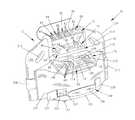
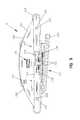
- FIG. 1is a perspective view of a hospital bed including a removable footboard of the present invention configured to include both bed frame and mattress controls, and a fluid supply, such as a blower or compressor, for supplying fluid to a fluid filled mattress on the bed;
- a fluid supplysuch as a blower or compressor
- FIG. 2is a partial perspective view illustrating the footboard of FIG. 1 coupled to a fluid filled mattress by a supply hose;
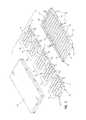
- FIG. 3is an exploded perspective view in partial schematic illustrating the various mattress zones of the fluid filled mattress of FIG. 1;
- FIG. 4is a front elevational view, with partial cut-aways, illustrating the removable footboard of FIG. 1;
- FIG. 5is a front perspective view of the removable footboard of FIG. 1 illustrating further details thereof;
- FIG. 6is a front perspective view of the footboard similar to FIG. 5, with the front cover removed;
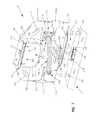
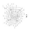
- FIG. 7is a rear perspective view of the removable footboard of FIG. 1 raised above the bed frame, with the support posts and the bed frame partially broken away for clarity;
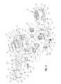
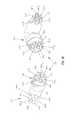
- FIG. 8is an exploded perspective view of the removable footboard of FIG. 1;
- FIG. 9is a bottom plan view of the removable footboard of FIG. 1;
- FIG. 10is a perspective view illustrating the interface coupling of the air hose assembly and the mattress interface connection assembly of FIG. 2;
- FIG. 11is a detailed perspective view of the footboard interface connection assembly and the relief member of the removable footboard of FIG. 1;
- FIG. 12is a block diagram illustrating the interconnection of the various control and fluid handling components of the removable footboard of FIG. 1 .
- FIG. 1illustrates a hospital bed 10 of the present invention.
- the bed 10includes a base frame 12 having a plurality of casters 14 , and a brake/steer control mechanism having pedals 16 mounted adjacent each of the casters 14 . Details of the structure and operation of the brake/steer control mechanism are disclosed in U.S. Pat. No. 6,321,878, which is assigned to the assignee of the present invention and the disclosure of which is expressly incorporated by reference herein.
- the bed 10further includes an elevating frame 20 coupled to the base frame 12 , and an articulating deck 22 coupled to the elevating frame 20 .
- the elevating frame 20may include a retracting frame as illustrated in U.S. Pat. No. 6,208,250, which is assigned to the assignee of the present invention and the disclosure of which is expressly incorporated by reference herein.
- a weigh frame(not shown) of the type disclosed in U.S. Pat. No. 6,208,250 may be coupled to the base frame 12 .
- the articulating deck 22illustratively includes a head deck section 23 , a seat deck section 24 , a thigh deck section 25 , and a leg deck section 26 .
- the deck sections 23 , 24 , 25 , and 26are movable to various positions in a conventional manner.
- a headboard 28is mounted to the elevating frame 20 adjacent a head end 29 of bed 10
- a footboard 30is mounted to the elevating frame 20 adjacent a foot end 31 of bed 10 .
- the footboard 30is removable from the frame 20 . Additional details of the supporting structure facilitating removal of the footboard 30 from the frame 20 are illustrated in U.S. Pat. No. 6,208,250.
- the bed 10further includes a pair of head end siderails 32 and a pair of foot end siderails 34 coupled to the articulating deck 22 on opposite sides of the bed 10 .
- the siderails 32 and 34are coupled to the articulating deck 22 in a conventional manner using connector mechanisms 35 , such as those described in detail in U.S. Pat. No. 6,208,250.
- the siderails 32 and 34are each movable between a lowered position and an elevated position located above a top surface or patent support surface 36 , as shown in FIG. 1 .
- the top surface 36is defined by a mattress 38 located on the articulating deck 22 and is configured to support a patient thereon.
- the mattress 38is an air mattress including upper and lower cushion levels or layers 40 and 42 .
- the upper cushion level 40provides a support surface for the patient and illustratively includes five separate groups or zones 44 , 46 , 48 , 50 , and 52 extending from the head end 29 to the foot end 31 of the bed 10 (FIGS. 1 and 3 ).
- the zonesinclude a head zone 44 , a chest zone 46 , a seat zone 48 , a thigh zone 50 , and a foot zone 52 .
- Each upper level zone 44 , 46 , 48 , 50 , and 52may be formed by a single cushion 54 including a plurality of generally rectangularly-shaped air bag segments or bladders 56 which are in fluid communication with each other within a single cushion 54 .
- the lower cushion layer 42illustratively includes a closed cell air bag or substrate 58 extending across the entire length and width of the elevating frame 20 .
- a plurality of bolsters 60may be formed on the lower substrate 58 along its side edges.
- the bolsters 60are illustratively integrally formed with the lower substrate 58 so that the interiors of the bolsters 60 are in fluid communication with the remainder of the substrate 58 .
- the bolsters 60nest within a space below the end portions of the bladders 56 .
- Releasable securing devicessuch as snaps 62 , are used to join the ends and sides of the cushioning layers 40 and 42 to side panels 64 placed around the sides of the mattress 38 .
- the side panels 64tend to hold the bolsters 60 in place.
- the bolsters 60tend to keep the upper cushioning layer 40 from shifting with respect to the lower cushioning layer 42 .
- a coverlet 66also may be placed about the upper and lower cushioning layers 40 and 42 to help secure them together as a single unit.
- the lower cushioning layer 42may also include a plurality of side release members, such as tie downs 68 , about its perimeter.
- the tie downs 68are used to secure the mattress 38 to the articulating deck 22 .
- the mattress 38is illustratively a low air loss mattress, although any type of air or fluid filled mattress may be used in accordance with the present invention.
- the low air loss mattress 38provides controlled air leakage to allow a limited amount of air to escape from the upper and lower cushioning layers 40 and 42 of the mattress 38 .
- the mattress 38may be of the type disclosed in U.S. Pat. No. 5,647,079, which is assigned to the assignee of the present invention and which is expressly incorporated by reference herein.
- the footboard 30includes a plurality of controls 70 , such as buttons, knobs, or switches for controlling various functions of the bed 10 and of devices associated with the bed 10 .
- the controls 70are supported on a top inclined panel 72 , a central inclined panel 74 and a lower inclined panel 76 .
- a cover 78is pivotably coupled to the footboard 30 by a pivot connection 80 (FIG. 7) so that the cover 78 can be pivoted downwardly to conceal at least those of the controls 70 located on the top inclined panel 72 .
- the controls 70 supported by the top inclined panel 72include a plurality of environment or accessory controls 82 , a plurality of lock out controls 84 , a plurality of bed position controls 86 , and a plurality of surface controls 88 .
- the accessory controls 82may include conventional push buttons 83 configured to activate and deactivate an entertainment device, such as a television or a radio, a night light, or a back light.
- the lock out controls 84may include conventional push buttons 85 configured to permit a caregiver to lock out selected functions normally controlled by a patient using patient controls (not shown) that are typically located on the head end side rails 32 .
- the lock out buttons 85may deactivate controls for head or knee articulation of the articulating deck 22 , and for a conventional high-low mechanism (not shown).
- the lock out buttons 85may deactivate controls for entertainment devices or lights of the type discussed above.
- a master lock out button 85may be provided to lock out all of the motors for controlling head and knee articulation and the high-low mechanism.
- the bed position controls 86may include conventional push buttons 87 configured to permit a caregiver to select preset configurations for the articulating deck 22 , and to raise or lower the elevating frame 20 .
- the bed position controls 86may further include buttons 87 to place the elevating frame 20 in either Trendelenburg or Reverse Trendelenburg positions.
- the surface controls 88may comprise conventional push buttons 89 configured to activate and deactivate the air mattress 38 , or to provide an automatic firm pressure setting of the air mattress 38 .
- the central inclined panel 74includes a plurality of indicators 90 , and in-bed scale controls 92 .
- the indicators 90illustratively include a Trendelenburg angle indicator 94 including an indicator member (not shown) supported for relative movement as the angular orientation of the bed frame 20 changes.
- a plurality of indicator lights 96illustratively light emitting diodes (LEDs), which may provide an indication of a plurality of different conditions, such as motor power off, ground loss, brake not set, bed not down, service required, and surface power off.
- the in-bed scale controls 92may include a plurality of conventional push buttons 98 configured to, for example, activate and deactivate a scale coupled to the weigh frame, reset the scale, and convert the units of measure.
- An indicator 100illustratively a liquid crystal display, is positioned adjacent the buttons 98 and is configured to display information associated with the in-bed scale.
- the lower inclined panel 76supports a plurality of air mattress controls 102 which are configured to allow a caregiver to control operation of the air mattress 38 .
- the air mattress controls 102may adjust pressure in the various zones 44 , 46 , 48 , 50 , and 52 of the mattress 38 or provide therapy to the patient supported on the air mattress 38 .
- the air mattress controls 102include a plurality of programming control buttons 104 associated with a display 106 for entering or adjusting a patient's height and weight.
- a controller 107(FIG. 12) is illustratively provided to automatically set the air zone pressures at base line pressures based upon the patient's height and weight.
- the air mattress controls 102further includes a zone pressure indicator 108 for providing an indication of the pressure supplied to each respective air zone 44 , 46 , 48 , 50 , and 52 of the air mattress 38 .
- the indicator 108may comprise a plurality of light emitting diodes (not shown) which are illuminated to provide a representation of pressure relative to base line pressures.
- a zone select button 110is provided below the indicator 108 and permits the caregiver to select a particular air zone 44 , 46 , 48 , 50 , or 52 for pressure adjustment.
- Pressure adjust buttons 112 and 114are positioned adjacent to the indicator 108 and are configured to permit the caregiver to manually increase or decrease, respectively, the pressure in the zone selected by the zone selection button 110 .
- a max inflate button 116is likewise provided adjacent to the indicator 108 and may be depressed to cause maximum inflation of all air zones 44 , 46 , 48 , 50 , and 52 of the air mattress 38 , thereby providing a firmer support surface for the patient.
- a seat deflate button 118is provided immediately below the max inflate button 116 and may be depressed by a caregiver to deflate the seat zone 48 and the thigh zone 50 of the air mattress 38 . Deflation of the seat zone 48 and the thigh zone 50 may be utilized, for example, when moving a patient to or from the bed 10 .
- the air mattress controls 102further include an alarm silence button 120 .
- an audible alarm 121(FIG. 12 ), such as a bell or buzzer, is illustratively activated. Depressing the alarm silence button 120 causes the audible alarm 121 to be temporarily silenced.
- a highly visible CPR button 122is supported on the lower inclined panel 76 . Depression of the CPR button 122 results in a rapid deflation of all air zones 44 , 46 , 48 , 50 , 52 and 58 as described in greater detail below.
- the CPR button 122is illustratively larger than the other controls 70 and may be identified by a color, such as red, distinct from the other controls 70 .
- the footboard 30includes a housing or body 124 supporting a removable cover 126 which encloses an interior region or chamber 128 (FIG. 6 ).
- the removable cover 126includes a releasable securing device, illustratively a plurality of L-shaped locking tabs 130 disposed adjacent opposing side edges of the cover 126 , for releasably securing the cover 126 to the body portion 124 .
- the locking tabs 130are receivable within a plurality of receiving slots 132 formed within an outer surface 134 of the body portion 124 (FIG. 6 ).
- the removable cover 126supports the lower inclined panel 76 and includes an air inlet or intake 135 .
- the air intake 135is illustratively formed as a grille in a lower portion of the removable cover 126 and provides fluid communication between atmosphere and the interior region 128 of the footboard 30 (FIG. 9 ).
- an internal frame 136includes a mounting member or bracket 138 extending between a pair of spaced apart support posts 140 and 142 within the interior region 128 .
- the left support post 140comprises a tubular member having a substantially rectangular cross-section
- the right support post 142comprises a tubular member having a substantially circular cross-section.
- the mounting member 138is configured to support internal pneumatic and electrical components, including a blower 144 and first and second air control valves 146 and 148 which are coupled to the blower 144 within the interior region 128 of the footboard 30 .
- the mounting member 138is secured to the left and right support posts 140 and 142 through left and right collars 150 and 152 , respectively.
- the left and right collars 150 and 152are fixed to an arcuate support 154 extending outwardly away from the body portion 124 of the footboard 30 .
- a downwardly extending shroud 156is connected to the arcuate support 154 through a mounting platform 158 .
- a pair of L-shaped securing brackets 160are fixed adjacent a lower end of the shroud 156 and threadably receive a pair of bolts 162 for securing the removable cover 126 to the body portion 124 of the footboard 30 .
- the blower 144is used to supply air to the low air loss mattress 38 .
- a compressor or other air supplymay be located within interior region 128 of footboard 30 instead of the blower 144 .
- another type of fluid supplysuch as a water recirculation unit or a water pump, may be located within the footboard 30 , if desired, when a water-filled mattress is used.
- the footboard 30 of the present inventionmay be utilized with any fluid filled device associated with a patent support apparatus.
- an inlet filter 166is coupled to the intake 168 of the blower 144 and filters particulate from the air passing therethrough.
- the inlet filter 166is of conventional design and may include a housing 170 fixed to an inner surface 172 of the interior region 128 of the footboard 30 , thereby at least partially supporting the blower 144 .
- a manifold 174is supported within the interior region 128 intermediate the blower 144 and the control valves 146 and 148 . As described in greater detail below, the manifold 174 includes a single intake 176 and first and second outlets 178 and 180 .
- the intake 176receives air from the outlet 181 of the blower 144 which is then divided into two separate air paths passing through the first and second outlets 178 and 180 .
- Conventional flexible tubing 182 and 184(FIG. 6) interconnects the first and second outlets 178 and 180 with the first and second control valves 146 and 148 , respectively.
- the controller 107is illustratively formed as a circuit board and is located within the interior region 128 of the footboard 30 .
- a power supply module 188is supported within the interior region 128 and is in electrical communication with the controller 107 .
- the power supply module 188illustratively comprises a conventional alternating current to direct current (AC to DC) converter provided in electrical communication with an external alternating current power source 190 (FIG. 12 ).
- a power switch 192is provided intermediate the external power source 190 and the AC to DC converter 188 .
- the power switch 192comprises a conventional rocker switch supported by the removable cover 126 .
- a pilot light(not shown) may be provided to indicate that AC input voltage is available to the footboard 30 .
- the external power source 190illustratively may be from 95V AC to 240V AC at 50 to 60 Hz.
- the AC to DC converter 188produces a 24V DC output that is supplied to the controller 107 , which internally generates 5V DC and 12V DC.
- the 5V DC sourceis used internally by the controller 107 for logic signals, and externally for a speed control signal for the blower 144 and for set signals for the control valves 146 and 148 .
- the 12V DCmay be used as a driver voltage for driving the control valves 146 and 148 and a CPR dump valve 316 (FIG. 12 ).
- a front bumper 194extends outwardly from the front wall 195 of the removable cover 126 .
- the front bumper 194includes a resilient contact or engagement member 196 fixed to the front wall 195 and a support 198 positioned within the interior region 128 of the footboard 30 .
- the support 198includes a body portion 200 coupled to a pair of spaced apart posts 202 and 204 .
- the posts 202 and 204are secured to the shroud 156 of the mounting member 138 by conventional bolts 206 .
- the resilient engagement member 196is aligned with the body portion 200 of the support 198 in order to protect the front wall 195 of the removable cover 126 from impact.
- the footboard 30also includes side bumpers 208 and 210 and apertures 212 and 214 .
- the apertures 212 and 214provide handles to facilitate movement of the bed 10 .
- both the headboard 28 and the footboard 30are made from a plastic material using a blow molding process. It should be understood, however, that the headboard 28 and footboard 30 may be made from other materials and from other processes, if desired.
- the controls 70 on the footboard 30are illustratively coupled through a connector assembly 215 to a bed, or second, controller 217 (FIG. 12) supported by the bed 10 .
- the controller 107 of the footboard 30is electrically coupled to the controller 217 of the bed 10 .
- the bed controller 217 and other bed electronicsare illustratively mounted on the frame 20 of the bed 10 as illustrated in U.S. Pat. No. 6,208,250.
- the connector assembly 215may also supply power to the power supply module 188 .
- a conventional power cord(not shown) may be wired to the power supply module 188 and plugged into an outlet receptacle (not shown) on the bed 10 .
- a first connector alignment apparatus 216is coupled to the footboard 30 and a second connector alignment apparatus 218 is coupled to the frame 20 of the bed 10 .
- the support posts 140 and 142 of the footboard 30are formed to include apertures 220 and 222 which slide over upwardly extending mounting posts 224 and 226 on the frame 20 during installation of the footboard 30 onto the frame 20 in the direction of arrow 228 in FIG. 4 .
- the apertures 220 and 222 defined by the support posts 140 and 142are configured to mate with the respective mounting posts 224 and 226 such that the footboard 30 may be mounted to the frame 20 in a single orientation.
- the mounting post 224has a substantially rectangular cross-section to mate with the substantially rectangular cross-section of the aperture 220 of the support post 140 .
- the mounting post 226has a substantially circular cross-section to mate with the substantially circular cross-section of the aperture 222 of the support post 142 .
- the posts 224 and 226 and the apertures 220 and 222provide initial alignment between the footboard 30 and the frame 20 .
- the first and second connector alignment apparatuses 216 and 218provide further alignment for male and female electrical connectors 230 and 232 , respectively.
- the first connector alignment apparatus 216is configured to support a pair of male electrical connectors 230
- the second connector alignment apparatus 218is configured to support a pair of female electrical connectors 232
- the first connector alignment apparatus 216further includes a base plate 234 having outwardly extending alignment posts 236 and 238 located at opposite ends.
- the posts 236 and 238each include tapered head portions 240 and 242 , respectively (FIGS. 4 and 7 ).
- the second connector alignment apparatus 218includes a body portion 244 formed to include apertures 246 and 248 at opposite ends.
- the apertures 246 and 248are configured to receive the posts 236 and 238 of the first connector alignment apparatus 216 .
- Lead-in ramp surfaces 250 and 252are formed around the apertures 246 and 248 (FIG. 4 ).
- initial alignmentis provided by posts 224 and 226 on the frame 20 extending into the apertures 220 and 222 formed in the footboard 30 .
- the posts 236 and 238 on the first connector alignment apparatus 216enter the apertures 246 and 248 in the second connector alignment apparatus 218 .
- the tapered surfaces 240 and 242 on the posts 236 and 238 and the ramp portions 250 and 252 of the apertures 246 and 248facilitate insertion of the posts 236 and 238 into the apertures 246 and 248 .
- the alignment apparatusesprovide an electrical connection to the footboard 30 automatically when the footboard 30 is installed on the frame 20 . Additional details of the first and second connector alignment apparatuses are disclosed in U.S. Pat. No. 6,208,250.
- airis supplied to the mattress 38 from the interior region 128 of the footboard 30 through an air hose assembly 254 .
- the air hose assembly 254provides fluid communication between a footboard interface connection assembly 256 located on a rear wall 257 of the footboard 30 , and a mattress interface connection assembly 258 , located on the left foot end of the mattress 38 .
- the air hose assembly 254comprises a plurality of independent air stream supply tubes 260 a-g bundled together and nested within an outer tube 262 (FIG. 10 ).
- Both ends of the air hose assembly 254may include an interface coupling 264 so that the air hose assembly 254 may be connected to deliver air from the blower 144 to the mattress 38 .
- the interface couplings 264 on each end of the air hose assembly 254are identical so that either end of the air hose assembly 254 may be attached to either the footboard interface connection assembly 256 or the mattress interface connection assembly 258 .
- the footboard interface connection assembly 256 and the mattress interface connection assembly 258are illustratively substantially identical and each include a plurality of male connection members 265 a-g .
- the male connection members 265 a-g of the footboard interface connection assembly 256are coupled to independent air stream supply tubes 266 a-g , respectively which in turn are connected to the blower 144 through the first and second control valves 146 and 148 (FIG. 11 ).
- the male connection members 265 a-g of the mattress interface connection assembly 258is likewise coupled to independent air stream supply tubes 267 a-g , respectively, which in turn are connected to the air mattress 38 .
- the interface couplings 264 of the air hose assembly 254illustratively include a plurality of female connection members 268 a-g coupled to the supply tubes 260 a-g of the air hose assembly 254 , respectively.
- the footboard interface connection assembly 256 and the mattress interface connection assembly 258sealingly mate with the interface couplings 264 of the air hose assembly 254 .
- the male connection members 265 a-gare sealingly received within the female connection members 268 a-g , thereby providing fluid communication between the interface connection assemblies 256 and 258 and their respective interface couplings 264 .
- An alignment mechanism 269ensures proper orientation of the connection assemblies 256 and 258 relative to their respective interface couplings 264 .
- the alignment mechanism 269includes a slot 270 formed within a coupling ring 271 of each interface connection assembly 256 and 258 , and a pin 272 coupled to each of the interface couplings 264 .
- the slot 270slidingly receives the pin 272 only when the connection assembly 256 and 258 is in a single, proper orientation relative to the respective interface coupling 264 .
- the footboard interface connection assembly 256is received within a relief member 273 supported by the rear wall 257 of the footboard 30 .
- the relief member 273includes a housing 274 extending inwardly from the rear wall 257 toward the interior region 128 of the footboard 30 .
- the housing 274includes first and second inclined sidewalls 275 and 276 connected to upper and lower walls 277 and 278 , thereby defining a relief or recess 279 .
- a mounting flange 280is connected to the rear wall 257 through conventional fasteners, such as bolts 281 .
- the footboard interface connection assembly 256is supported by an aperture 282 formed within the first inclined wall 275 .
- the footboard 30further includes an instruction receptacle 284 supported by the rear wall 257 of the footboard 30 .
- the instruction receptacle 284includes a pair of side walls 286 and 288 coupled to an outer wall 289 and defining an interior region 290 .
- An upper end 291 of the instruction receptacle 284is open to provide access to the interior region 290 .
- Each of the side walls 286 and 288includes an arcuate lower portion 292 and 294 which defines a fluid passage 296 .
- the arcuate lower portions 292 and 294are configured to direct fluids downwardly toward the lower end 298 of the instruction receptacle 284 and out through the fluid passage 296 .
- a plurality of cards 300are illustratively received within the interior region 290 of the instruction receptacle 284 .
- the cards 300may comprise instruction sheets for use by a caregiver positioned adjacent to the footboard 30 .
- a guide member 302is associated with the cards 300 and is configured to guide the cards 300 in movement from within the interior region 290 through the open upper end 291 .
- the guide member 302illustratively includes a pair of pins 304 and 306 slidably received within a pair of slots 308 and 310 formed within each of the plurality of cards 300 (FIG. 8 ).
- Operation of the air supply components of the footboard 30is represented schematically in FIG. 12 .
- AC poweris supplied by the external power source 190 to the AC to DC converter 188 .
- Desired settings for the air mattress 38may be entered through controls 70 on the lower inclined control panel 76 , which is in communication with the controller 107 .
- the controller 107activates the blower 144 and the control valves 146 and 148 as required to maintain desired pressures within the zones 44 , 46 , 48 , 50 , 52 , and 58 of the air mattress 38 .
- a conventional blower control 312provides an interface between the blower 144 and the controller 107 . More particularly, the AC to DC converter 188 provides 24V DC to the blower control 312 , which is used to generates the necessary stepper signals to run the blower 144 .
- a 0V DC to 5V DC blower speed signalis supplied to the blower control 312 by the controller 107 . When operating in a standard condition, the blower speed signal is approximately 4 V DC.
- the blower 144draws air from the atmosphere through the intake 135 formed in the removable cover 126 .
- the airpasses through the inlet filter 166 and into the blower 144 through the intake 168 .
- Airis forced out of the blower 144 through the outlet 181 and then into the manifold 174 .
- the manifold 174supplies the pressurized air stream to control valves 146 and 148 . More particularly, the air stream enters the manifold 174 through the intake 176 and is then separated to pass through the first outlet 178 and the second outlet 180 . Tubing 182 and 184 directs the separated air streams to the first and second control valves 146 and 148 .
- Each control valve 146 and 148illustratively comprises three zone proportional valves 314 . As the separated air streams pass through the control valves 146 and 148 , they are further divided into a total of six independent air streams.
- the number of proportional valves 314equals the number of independent air streams to be directed to the mattress 38 . As may be appreciated, the number of proportional valves 314 may be varied depending upon the number of separately inflatable air bladders or bags included within the mattress 38 .
- each independent air streamand therefore air mattress zone 44 , 46 , 48 , 50 , 52 and 58 , is regulated by the opening and closing of its respective proportional valve 314 .
- the proportional valves 314automatically adjust in response to a signal received from the controller 107 , so that their actual output pressures substantially match desired output pressures.
- the comparison between actual output pressures and desired output pressuresis carried out for each valve by a conventional microprocessor (not shown) within the controller 107 .
- Actual output pressuresare measured using pressure transducers (not shown) located at the proportional valves 314 .
- the desired output pressuresare calculated by the microprocessor based upon the inputs received from the controls 70 on the footboard 30 .
- the desired output pressuremay be generated by the controller 107 based upon a patient's height and weight.
- the controller 107controls the speed of the blower 144 .
- the controller 107detects that the actual output pressure at a valve 314 is less than the desired output pressure, the controller 107 signals one of the valves 314 to open so that the actual pressure increases. If the pressure in the manifold 174 is insufficient to increase the actual output pressure after the opening of the valve 314 , the controller 107 signals the blower control 312 to increase the speed of the blower 144 . Then, as the actual output pressure increases, and the desired output pressure is exceeded, the controller 107 decreases the flow of valve 314 and reduces the speed of the blower 144 .
- the controller 186When a zone proportional valve 314 is unable to match the desired pressure with the correct amount of air pressure, the controller 186 will send an alarm signal to the alarm 121 .
- the alarm 121will provide an audible signal which may be temporarily silenced by depressing the alarm silence button 120 .
- the temperature of air supplied by the blower 144is monitored by a thermometer, illustratively a thermistor 318 .
- the thermistor 318is continually monitored by the controller 107 for continuity to ensure that it has not been opened. As the temperature of the air supplied by the blower 144 rises, the resistance of the thermistor 318 decreases, allowing a voltage signal back to the controller 107 to increase.
- An alarm conditionis activated if the thermistor opens, or if the measured air temperature rises above a predetermined temperature.
- the predetermined temperatureis approximately 150° F. (66° C.), which is based on providing an air temperature to the mattress 38 below approximately 105° F. (41° C.).
- the controller 107disables the blower 144 , illuminates a “service required” indicator light 96 on the central inclined panel 74 , and activate the audible alarm 121 .
- the independent air streamspass from the proportional valves 314 through a CPR dump valve 316 , and then into the air supply tubes 260 a-g of the air hose assembly 254 .
- the CPR dump valve 316is an electronically controlled valve actuable to vent all of the independent air streams to the atmosphere simultaneously while air flow from the manifold 174 is stopped.
- a caregiverenters a command on the control panel or activates the CPR button 122 located on the housing 124 . This sends a signal to the controller 107 to open the CPR valve 316 and to stop the flow of air from the manifold 174 .
- the present inventionalso provides that a manual CPR condition may be accomplished by disconnecting the hose assembly 254 from either the footboard 30 , thereby allowing air to escape from the mattress 38 .
- a manual CPR conditionmay be accomplished by disconnecting the hose assembly 254 from either the footboard 30 , thereby allowing air to escape from the mattress 38 .
- the net result of either manner of operationis the rapid deflation under the weight of the patient of all of the zones 44 , 46 , 48 , 50 , 52 and 58 of the mattress 38 .
- the footboard 30 and the blower 144 , or other fluid supplyare formed integrally as a single unit. Therefore, it is not required to couple a separate blower housing to the footboard 30 or other part of the bed 10 in order to supply air to the mattress 38 .
- the bed 10 illustrated in U.S. Pat. No. 6,208,250is used with a conventional foam, inner spring or static air mattress.
- the footboard shown in U.S. Pat. No. 6,208,250is removed and replaced with the footboard 30 shown in the present application. This provides an integral blower 144 , or other fluid supply, for the mattress 38 supported within the footboard 30 on the bed 10 .
- blower 144is illustratively located within the footboard 30 , it is understood that the blower 144 , or other fluid supply, may be located in an interior region of the headboard 28 or in an interior region of one of the siderails 32 and 34 .
- the headboard 28 , the footboard 30 , and the siderails 32 and 34illustratively provide barriers which extend above the top surface 36 of mattress 38 and which are coupled to the frame 20 or articulating deck 22 of the bed 10 . Therefore, the present invention provides a fluid supply, such as blower 144 , located within an interior region of a barrier coupled to a hospital bed 10 .
- the footboard 30includes access panels or doors 320 configured to cover internal chambers 322 . More particularly, the access doors 320 are pivotally coupled to the front wall 195 of the removable cover 126 utilizing conventional mechanisms, such as hinges (not shown). Alternatively, the access doors 320 may be supported for sliding movement relative to the front wall 195 for providing access to the internal chambers 322 .
- the interior region 128 of the footboard 30is configured to provide space for the internal chambers 322 to extend therein.
- the chambers 322are illustratively configured to receive control modules 324 .
- the control modules 324include electrical connectors and valves (not shown) for providing various types of therapy to a patient supported on the bed 10 .
- different control modules 324can be provided for rotation therapy, percussion/vibration therapy, sequential compression therapy, or other type of therapy. Details of the control modules 324 are included in U.S. Pat. Nos. 5,715,548 and 6,047,424, and in U.S. patent application Ser. No. 09/532,592, all of which are assigned to the assignee of the present invention and are expressly incorporated by reference herein.
- the doors 320can provide access to storage chambers 322 for storing other items, such as medical supplies, within the interior region 128 of the footboard 30 .
- a compression boot or other compression device(not shown) is stored within interior region 128 of the footboard 30 and is accessible through the door 320 on the footboard 30 . If necessary, a separate compressor (not shown) for the compression device may also be stored in interior region 128 of footboard 30 . The compression device is removable from the interior region 128 to provide therapy to the patient supported on the mattress 38 .
Landscapes
- Health & Medical Sciences (AREA)
- Nursing (AREA)
- Life Sciences & Earth Sciences (AREA)
- Animal Behavior & Ethology (AREA)
- General Health & Medical Sciences (AREA)
- Public Health (AREA)
- Veterinary Medicine (AREA)
- Invalid Beds And Related Equipment (AREA)
- Mattresses And Other Support Structures For Chairs And Beds (AREA)
- Magnetic Resonance Imaging Apparatus (AREA)
- Radiation-Therapy Devices (AREA)
Abstract
Description
Claims (46)
Priority Applications (2)
| Application Number | Priority Date | Filing Date | Title |
|---|---|---|---|
| US10/261,771US6829796B2 (en) | 2001-10-02 | 2002-10-01 | Integrated barrier and fluid supply for a hospital bed |
| US11/011,658US7310839B2 (en) | 2001-10-02 | 2004-12-14 | Patient support apparatus |
Applications Claiming Priority (3)
| Application Number | Priority Date | Filing Date | Title |
|---|---|---|---|
| US32650001P | 2001-10-02 | 2001-10-02 | |
| US37587402P | 2002-04-26 | 2002-04-26 | |
| US10/261,771US6829796B2 (en) | 2001-10-02 | 2002-10-01 | Integrated barrier and fluid supply for a hospital bed |
Related Child Applications (1)
| Application Number | Title | Priority Date | Filing Date |
|---|---|---|---|
| US11/011,658DivisionUS7310839B2 (en) | 2001-10-02 | 2004-12-14 | Patient support apparatus |
Publications (2)
| Publication Number | Publication Date |
|---|---|
| US20030061664A1 US20030061664A1 (en) | 2003-04-03 |
| US6829796B2true US6829796B2 (en) | 2004-12-14 |
Family
ID=26985437
Family Applications (2)
| Application Number | Title | Priority Date | Filing Date |
|---|---|---|---|
| US10/261,771Expired - LifetimeUS6829796B2 (en) | 2001-10-02 | 2002-10-01 | Integrated barrier and fluid supply for a hospital bed |
| US11/011,658Expired - Fee RelatedUS7310839B2 (en) | 2001-10-02 | 2004-12-14 | Patient support apparatus |
Family Applications After (1)
| Application Number | Title | Priority Date | Filing Date |
|---|---|---|---|
| US11/011,658Expired - Fee RelatedUS7310839B2 (en) | 2001-10-02 | 2004-12-14 | Patient support apparatus |
Country Status (6)
| Country | Link |
|---|---|
| US (2) | US6829796B2 (en) |
| EP (1) | EP1448148B1 (en) |
| AT (1) | ATE409449T1 (en) |
| CA (1) | CA2461167A1 (en) |
| DE (1) | DE60229160D1 (en) |
| WO (1) | WO2003028610A1 (en) |
Cited By (84)
| Publication number | Priority date | Publication date | Assignee | Title |
|---|---|---|---|---|
| US20050005811A1 (en)* | 2003-07-08 | 2005-01-13 | Heyden Thomas J. | Electro-pneumatic retarder control |
| US20060156473A1 (en)* | 2004-12-15 | 2006-07-20 | Chambers Kenith W | Quick connector for multi-media |
| US20060195986A1 (en)* | 2005-03-07 | 2006-09-07 | Reza Hakamiun | Footboard for a hospital bed |
| US20070130692A1 (en)* | 2005-10-27 | 2007-06-14 | Guy Lemire | Ergonomic control apparatus for a patient support apparatus |
| US20070163045A1 (en)* | 2005-11-07 | 2007-07-19 | Stryker Corporation | Patient handling device including local status indication, one-touch fowler angle adjustment, and power-on alarm configuration |
| US7263734B1 (en)* | 2006-11-15 | 2007-09-04 | Gaymar Industries, Inc. | Magnetically retained CPR dump |
| WO2007008831A3 (en)* | 2005-07-08 | 2007-10-11 | Hill Rom Co Inc | Control unit for patient support |
| US7319386B2 (en) | 2004-08-02 | 2008-01-15 | Hill-Rom Services, Inc. | Configurable system for alerting caregivers |
| US20080109964A1 (en)* | 2006-11-14 | 2008-05-15 | Thierry Flocard | Control System For Hospital Bed Mattress |
| US20080172789A1 (en)* | 2005-12-19 | 2008-07-24 | Stryker Corporation | Patient support with improved control |
| US20080250564A1 (en)* | 2007-04-13 | 2008-10-16 | Stryker Corporation | Patient support with universal energy supply system |
| US20080263771A1 (en)* | 2007-04-27 | 2008-10-30 | Hill-Rom Services, Inc. | Endboard for a patient support |
| US7676862B2 (en) | 2004-09-13 | 2010-03-16 | Kreg Medical, Inc. | Siderail for hospital bed |
| US20100076356A1 (en)* | 2003-04-11 | 2010-03-25 | Biondo John P | System for compression therapy |
| US7743441B2 (en) | 2004-09-13 | 2010-06-29 | Kreg Therapeutics, Inc. | Expandable width bed |
| US7757318B2 (en) | 2004-09-13 | 2010-07-20 | Kreg Therapeutics, Inc. | Mattress for a hospital bed |
| US7779494B2 (en) | 2004-09-13 | 2010-08-24 | Kreg Therapeutics, Inc. | Bed having fixed length foot deck |
| US7852208B2 (en) | 2004-08-02 | 2010-12-14 | Hill-Rom Services, Inc. | Wireless bed connectivity |
| US7861334B2 (en)* | 2005-12-19 | 2011-01-04 | Stryker Corporation | Hospital bed |
| US7868740B2 (en) | 2007-08-29 | 2011-01-11 | Hill-Rom Services, Inc. | Association of support surfaces and beds |
| US20110113562A1 (en)* | 2009-11-16 | 2011-05-19 | Uzzle Thomas E | Endboard for person support apparatus |
| US20110131725A1 (en)* | 2009-12-09 | 2011-06-09 | Kci Licensing, Inc. | Patient support system with modular integrated fluid supply system |
| US20110140869A1 (en)* | 2009-12-10 | 2011-06-16 | Wei-Ting Liu | Patient Bed |
| US20110169653A1 (en)* | 2010-01-14 | 2011-07-14 | Jack Xiao Peng Wang | Person-support apparatus height indicator |
| US20110214234A1 (en)* | 2010-03-02 | 2011-09-08 | Herman Fred J | Multifunctional display for hospital bed |
| US20110232001A1 (en)* | 2008-06-27 | 2011-09-29 | Craig Poulos | Bed gap filler |
| US8046625B2 (en) | 2008-02-22 | 2011-10-25 | Hill-Rom Services, Inc. | Distributed fault tolerant architecture for a healthcare communication system |
| US8272892B2 (en) | 2003-08-21 | 2012-09-25 | Hill-Rom Services, Inc. | Hospital bed having wireless data capability |
| US8461968B2 (en) | 2007-08-29 | 2013-06-11 | Hill-Rom Services, Inc. | Mattress for a hospital bed for use in a healthcare facility and management of same |
| US8537008B2 (en) | 2008-09-19 | 2013-09-17 | Hill-Rom Services, Inc. | Bed status indicators |
| US8539625B2 (en) | 2009-09-23 | 2013-09-24 | Kreg Medical Inc. | Bed gap shield |
| US8572778B2 (en) | 2007-03-30 | 2013-11-05 | Hill-Rom Services, Inc. | User interface for hospital bed |
| US8779924B2 (en) | 2010-02-19 | 2014-07-15 | Hill-Rom Services, Inc. | Nurse call system with additional status board |
| US8914924B2 (en) | 2007-04-13 | 2014-12-23 | Stryker Corporation | Patient support with universal energy supply system |
| US20150089748A1 (en)* | 2012-05-03 | 2015-04-02 | Linet Spol S.R.O. | Pneumatic mattress |
| US9119753B2 (en) | 2008-06-27 | 2015-09-01 | Kreg Medical, Inc. | Bed with modified foot deck |
| US9205010B2 (en) | 2010-09-01 | 2015-12-08 | Huntleigh Technology Limited | Patient support apparatuses and methods |
| US9228885B2 (en) | 2012-06-21 | 2016-01-05 | Hill-Rom Services, Inc. | Patient support systems and methods of use |
| US9411934B2 (en) | 2012-05-08 | 2016-08-09 | Hill-Rom Services, Inc. | In-room alarm configuration of nurse call system |
| US9492341B2 (en) | 2010-10-08 | 2016-11-15 | Hill-Rom Services, Inc. | Hospital bed with graphical user interface having advanced functionality |
| US9539155B2 (en) | 2012-10-26 | 2017-01-10 | Hill-Rom Services, Inc. | Control system for patient support apparatus |
| US9642759B2 (en) | 2007-04-13 | 2017-05-09 | Stryker Corporation | Patient support with universal energy supply system |
| US9655798B2 (en) | 2013-03-14 | 2017-05-23 | Hill-Rom Services, Inc. | Multi-alert lights for hospital bed |
| US9734293B2 (en) | 2007-10-26 | 2017-08-15 | Hill-Rom Services, Inc. | System and method for association of patient care devices to a patient |
| US9830424B2 (en) | 2013-09-18 | 2017-11-28 | Hill-Rom Services, Inc. | Bed/room/patient association systems and methods |
| US9827157B2 (en) | 2006-02-08 | 2017-11-28 | Hill-Rom Services, Inc. | User module for a patient support |
| US9875633B2 (en) | 2014-09-11 | 2018-01-23 | Hill-Rom Sas | Patient support apparatus |
| US10045715B2 (en) | 2015-04-27 | 2018-08-14 | Hill-Rom Services, Inc. | Self-compensating bed scale system for removable components |
| US10054479B2 (en) | 2015-05-05 | 2018-08-21 | Hill-Rom Services, Inc. | Bed with automatic weight offset detection and modification |
| US20180289174A1 (en)* | 2017-04-10 | 2018-10-11 | Hill-Rom Services, Inc. | Mattress overlay for p&v, turn assist and mcm |
| US10136815B2 (en) | 2012-09-24 | 2018-11-27 | Physio-Control, Inc. | Patient monitoring device with remote alert |
| US10176297B2 (en) | 2001-08-03 | 2019-01-08 | Hill-Rom Services, Inc. | Hospital bed computer system having EMR charting capability |
| US10206836B2 (en) | 2011-11-11 | 2019-02-19 | Hill-Rom Services, Inc. | Bed exit alerts for person support apparatus |
| US10507158B2 (en)* | 2016-02-18 | 2019-12-17 | Hill-Rom Services, Inc. | Patient support apparatus having an integrated limb compression device |
| USD877915S1 (en) | 2018-09-28 | 2020-03-10 | Stryker Corporation | Crib assembly |
| USD879966S1 (en) | 2018-09-28 | 2020-03-31 | Stryker Corporation | Crib assembly |
| US10667984B2 (en) | 2015-12-18 | 2020-06-02 | Stryker Corporation | Systems and methods for operating patient therapy devices |
| USD888964S1 (en) | 2018-09-28 | 2020-06-30 | Stryker Corporation | Crib assembly for a patient support |
| USD888963S1 (en) | 2018-09-28 | 2020-06-30 | Stryker Corporation | Cover assembly for a patient support |
| USD888962S1 (en) | 2018-09-28 | 2020-06-30 | Stryker Corporation | Cover assembly for a patient support |
| USD890914S1 (en) | 2018-10-31 | 2020-07-21 | Stryker Corporation | Pump |
| USD892159S1 (en) | 2018-10-31 | 2020-08-04 | Stryker Corporation | Display screen with animated graphical user interface |
| USD893543S1 (en) | 2018-10-31 | 2020-08-18 | Stryker Corporation | Display screen with graphical user interface |
| USD894226S1 (en) | 2018-10-31 | 2020-08-25 | Stryker Corporation | Display screen or portion thereof with graphical user interface |
| USD894223S1 (en) | 2018-10-31 | 2020-08-25 | Stryker Corporation | Display screen with animated graphical user interface |
| USD894957S1 (en) | 2018-10-31 | 2020-09-01 | Stryker Corporation | Display screen or portion thereof with graphical user interface |
| USD894956S1 (en) | 2018-10-31 | 2020-09-01 | Stryker Corporation | Display screen or portion thereof with graphical user interface |
| USD901940S1 (en) | 2018-09-28 | 2020-11-17 | Stryker Corporation | Patient support |
| US10945902B2 (en) | 2017-11-13 | 2021-03-16 | Stryker Corporation | Techniques for controlling actuators of a patient support apparatus |
| US11044996B2 (en)* | 2014-07-25 | 2021-06-29 | Stryker Corporation | Medical support apparatus |
| US11173085B2 (en) | 2017-12-28 | 2021-11-16 | Stryker Corporation | Mattress cover for a mattress providing rotation therapy to a patient |
| US11246776B2 (en) | 2005-12-19 | 2022-02-15 | Stryker Corporation | Patient support with improved control |
| US11246775B2 (en) | 2017-12-28 | 2022-02-15 | Stryker Corporation | Patient turning device for a patient support apparatus |
| US11410771B2 (en) | 2017-06-01 | 2022-08-09 | Stryker Corporation | Patient care devices with open communication |
| US11504061B2 (en) | 2017-03-21 | 2022-11-22 | Stryker Corporation | Systems and methods for ambient energy powered physiological parameter monitoring |
| US11559451B2 (en) | 2018-10-31 | 2023-01-24 | Stryker Corporation | Fluid source for supplying fluid to therapy devices |
| USD977109S1 (en) | 2018-09-28 | 2023-01-31 | Stryker Corporation | Crib assembly for a patient support |
| US11654075B2 (en)* | 2019-03-29 | 2023-05-23 | Hill-Rom Sevices, Inc. | Method and apparatus for upgrading a patient support apparatus to include an integrated patient therapy device |
| US11911325B2 (en) | 2019-02-26 | 2024-02-27 | Hill-Rom Services, Inc. | Bed interface for manual location |
| US11974964B2 (en) | 2019-03-29 | 2024-05-07 | Hill-Rom Services, Inc. | Patient support apparatus with integrated patient therapy device |
| US12150908B2 (en) | 2014-04-18 | 2024-11-26 | Kreg Medical, Inc. | Patient support with stand-up and sit features |
| US12186241B2 (en) | 2021-01-22 | 2025-01-07 | Hill-Rom Services, Inc. | Time-based wireless pairing between a medical device and a wall unit |
| US12251243B2 (en) | 2008-02-22 | 2025-03-18 | Hill-Rom Services, Inc. | Distributed healthcare communication system |
| US12279999B2 (en) | 2021-01-22 | 2025-04-22 | Hill-Rom Services, Inc. | Wireless configuration and authorization of a wall unit that pairs with a medical device |
Families Citing this family (19)
| Publication number | Priority date | Publication date | Assignee | Title |
|---|---|---|---|---|
| DE60323137D1 (en)* | 2002-11-12 | 2008-10-02 | Gray Tek Inc | MATERIAL DRIVE WITH A LIQUID FILM MEMORY |
| US7543583B2 (en)* | 2004-07-28 | 2009-06-09 | Hill-Rom Services, Inc. | Forced air vent in siderail |
| US20060117482A1 (en)* | 2004-12-07 | 2006-06-08 | Branson Gregory W | Touch screen control for lateral rotation of a hospital bed mattress |
| US7884735B2 (en) | 2005-02-11 | 2011-02-08 | Hill-Rom Services, Inc. | Transferable patient care equipment support |
| US20070209119A1 (en)* | 2006-03-10 | 2007-09-13 | Apex Medical Corp. | Air mattress system |
| WO2009006517A2 (en)* | 2007-07-03 | 2009-01-08 | Optimus Services, Llc | Medical table surface and pads |
| US10667622B1 (en)* | 2008-07-30 | 2020-06-02 | Youngblood Ip Holdings, Llc | Multi-zone temperature modulation system for bed or blanket |
| US20100325805A1 (en)* | 2009-06-24 | 2010-12-30 | Kraus Jeffrey G | Foot Brace For Bed |
| US8474072B2 (en) | 2010-09-28 | 2013-07-02 | Hill-Rom Services, Inc. | Hospital bed with chair lockout |
| USD690424S1 (en) | 2011-01-26 | 2013-09-24 | Sage Products, Inc. | Set of components for a patient repositioning system |
| US20130074268A1 (en)* | 2011-09-23 | 2013-03-28 | Timothy Joseph Receveur | Structural pneumatic accumulator system |
| US10322045B1 (en)* | 2013-05-29 | 2019-06-18 | Paul Cuneo | Footboard for hospital bed with therapeutic mechanisms housed within |
| AU2014317772B2 (en)* | 2013-09-06 | 2019-04-11 | Stryker Corporation | Patient support usable with bariatric patients |
| EP3158611B1 (en)* | 2014-06-20 | 2020-09-02 | Smiths Interconnect Americas, Inc. | Connectors |
| EP3205268B1 (en) | 2016-02-11 | 2023-10-25 | Hill-Rom Services, Inc. | Hospital bed |
| US11389354B2 (en) | 2017-11-30 | 2022-07-19 | Stryker Corporation | Multi-function headboard for patient support apparatus |
| US12150905B2 (en) | 2018-11-27 | 2024-11-26 | Stryker Corporation | Patient support apparatus with notification system |
| US12329717B2 (en)* | 2019-03-29 | 2025-06-17 | Hill-Rom Services, Inc. | Control system for a patient therapy device |
| US11931312B2 (en) | 2019-03-29 | 2024-03-19 | Hill-Rom Services, Inc. | User interface for a patient support apparatus with integrated patient therapy device |
Citations (46)
| Publication number | Priority date | Publication date | Assignee | Title |
|---|---|---|---|---|
| US4051522A (en) | 1975-05-05 | 1977-09-27 | Jonathan Systems | Patient monitoring system |
| US4539560A (en) | 1982-12-10 | 1985-09-03 | Hill-Rom Company, Inc. | Bed departure detection system |
| US4633237A (en) | 1984-07-11 | 1986-12-30 | Kenneth A. Tucknott | Patient bed alarm system |
| US4638519A (en) | 1985-04-04 | 1987-01-27 | Air Plus, Inc. | Fluidized hospital bed |
| US4793428A (en) | 1988-02-29 | 1988-12-27 | Cobe Asdt, Inc. | Hospital bed with an integrated scale |
| US4862921A (en) | 1988-07-29 | 1989-09-05 | Jack Hess | Air distribution system for air support convalescent beds |
| US4907845A (en) | 1988-09-16 | 1990-03-13 | Salomon Sa | Bed patient monitoring system |
| US4926951A (en) | 1989-06-26 | 1990-05-22 | Ssi Medical Services, Inc. | Weigh bed |
| US4934468A (en) | 1987-12-28 | 1990-06-19 | Hill-Rom Company, Inc. | Hospital bed for weighing patients |
| US4953244A (en) | 1987-12-28 | 1990-09-04 | Hill-Rom Company, Inc. | Hospital bed for weighing patients |
| US4974692A (en) | 1989-06-26 | 1990-12-04 | Ssi Medical Services, Inc. | Weigh bed |
| US5051673A (en) | 1985-12-30 | 1991-09-24 | Goodwin Vernon L | Patient support structure |
| US5182826A (en) | 1989-03-09 | 1993-02-02 | Ssi Medical Services, Inc. | Method of blower control |
| US5235319A (en) | 1992-05-11 | 1993-08-10 | Joseph C. Hill | Patient monitoring system |
| US5267364A (en) | 1992-08-11 | 1993-12-07 | Kinetic Concepts, Inc. | Therapeutic wave mattress |
| US5269388A (en) | 1991-11-12 | 1993-12-14 | Stress-Tek, Inc. | Weighing bed |
| US5276432A (en) | 1992-01-15 | 1994-01-04 | Stryker Corporation | Patient exit detection mechanism for hospital bed |
| US5279010A (en) | 1988-03-23 | 1994-01-18 | American Life Support Technology, Inc. | Patient care system |
| US5335313A (en) | 1991-12-03 | 1994-08-02 | Douglas Terry L | Voice-actuated, speaker-dependent control system for hospital bed |
| US5393935A (en) | 1993-07-09 | 1995-02-28 | Ch Administration, Inc. | Portable scale |
| US5410297A (en) | 1993-01-11 | 1995-04-25 | R. F. Technologies, Inc. | Capacitive patient presence monitor |
| US5425148A (en) | 1993-10-20 | 1995-06-20 | Ss1 Medical Services, Inc. | Convertible footboard for a patient support |
| US5586346A (en) | 1994-02-15 | 1996-12-24 | Support Systems, International | Method and apparatus for supporting and for supplying therapy to a patient |
| US5611096A (en) | 1994-05-09 | 1997-03-18 | Kinetic Concepts, Inc. | Positional feedback system for medical mattress systems |
| US5623736A (en) | 1994-12-09 | 1997-04-29 | Suport Systems, International | Modular inflatable/air fluidized bed |
| US5647079A (en) | 1996-03-20 | 1997-07-15 | Hill-Rom, Inc. | Inflatable patient support surface system |
| US5699038A (en) | 1993-07-12 | 1997-12-16 | Hill-Rom, Inc. | Bed status information system for hospital beds |
| US5715548A (en) | 1994-01-25 | 1998-02-10 | Hill-Rom, Inc. | Chair bed |
| US5771511A (en) | 1995-08-04 | 1998-06-30 | Hill-Rom, Inc. | Communication network for a hospital bed |
| EP0860803A2 (en) | 1997-02-25 | 1998-08-26 | Lunan Products Limited | Carer's monitoring system |
| US5802640A (en) | 1992-04-03 | 1998-09-08 | Hill-Rom, Inc. | Patient care system |
| US5808552A (en) | 1996-11-25 | 1998-09-15 | Hill-Rom, Inc. | Patient detection system for a patient-support device |
| US5944494A (en) | 1997-04-29 | 1999-08-31 | Hill-Rom, Inc. | Blower apparatus mounted in a housing without a rigid connection |
| US5971913A (en) | 1995-09-25 | 1999-10-26 | Hill-Rom, Inc. | Noise and light monitor apparatus |
| US6021533A (en) | 1997-08-25 | 2000-02-08 | Hill-Rom, Inc. | Mattress apparatus having a siderail down sensor |
| US6047424A (en) | 1995-08-04 | 2000-04-11 | Hill-Rom, Inc. | Bed having modular therapy devices |
| US6067019A (en) | 1996-11-25 | 2000-05-23 | Hill-Rom, Inc. | Bed exit detection apparatus |
| US6073289A (en) | 1997-12-18 | 2000-06-13 | Hill-Rom, Inc. | Air fluidized bed |
| US6158070A (en) | 1999-08-27 | 2000-12-12 | Hill-Rom, Inc. | Coverlet for an air bed |
| US6178576B1 (en) | 1999-04-08 | 2001-01-30 | Jack L. Newell | Deflector attachment for an adjustable bed |
| US6208250B1 (en) | 1999-03-05 | 2001-03-27 | Hill-Rom, Inc. | Patient position detection apparatus for a bed |
| US6212718B1 (en) | 1998-03-31 | 2001-04-10 | Hill-Rom, Inc | Air-over-foam mattress |
| US20010001163A1 (en) | 1995-01-03 | 2001-05-17 | Allen E. David | Hospital bed and mattress having a retracting foot section |
| US6290194B1 (en) | 1999-01-19 | 2001-09-18 | Hill-Rom Services, Inc. | Blower unit retention apparatus |
| US6321878B1 (en) | 1999-03-05 | 2001-11-27 | Hill-Rom Services, Inc. | Caster and braking system |
| US6467111B1 (en) | 2000-03-13 | 2002-10-22 | Kci Licensing, Inc. | Medical bed system with interchangeable modules for mattress systems and related methods |
Family Cites Families (5)
| Publication number | Priority date | Publication date | Assignee | Title |
|---|---|---|---|---|
| US2097751A (en)* | 1936-05-18 | 1937-11-02 | Baltich Michael | Body-resting device |
| US2186142A (en)* | 1939-03-20 | 1940-01-09 | Harry L Lieberman | Furniture |
| US3867731A (en)* | 1972-06-12 | 1975-02-25 | Earl J Isaac | Liquid supporting furniture |
| CA1309560C (en)* | 1986-09-09 | 1992-11-03 | John H. Vrzalik | Method and apparatus for alternating pressure of a low air loss patient support system |
| US6892405B1 (en)* | 1994-05-09 | 2005-05-17 | Kci Licensing, Inc. | Therapeutic bed and related apparatus and methods |
- 2002
- 2002-10-01EPEP02776064Apatent/EP1448148B1/ennot_activeExpired - Lifetime
- 2002-10-01CACA002461167Apatent/CA2461167A1/ennot_activeAbandoned
- 2002-10-01WOPCT/US2002/031189patent/WO2003028610A1/ennot_activeApplication Discontinuation
- 2002-10-01DEDE60229160Tpatent/DE60229160D1/ennot_activeExpired - Lifetime
- 2002-10-01ATAT02776064Tpatent/ATE409449T1/ennot_activeIP Right Cessation
- 2002-10-01USUS10/261,771patent/US6829796B2/ennot_activeExpired - Lifetime
- 2004
- 2004-12-14USUS11/011,658patent/US7310839B2/ennot_activeExpired - Fee Related
Patent Citations (53)
| Publication number | Priority date | Publication date | Assignee | Title |
|---|---|---|---|---|
| US4051522A (en) | 1975-05-05 | 1977-09-27 | Jonathan Systems | Patient monitoring system |
| US4539560A (en) | 1982-12-10 | 1985-09-03 | Hill-Rom Company, Inc. | Bed departure detection system |
| US4633237A (en) | 1984-07-11 | 1986-12-30 | Kenneth A. Tucknott | Patient bed alarm system |
| US4638519A (en) | 1985-04-04 | 1987-01-27 | Air Plus, Inc. | Fluidized hospital bed |
| US5051673A (en) | 1985-12-30 | 1991-09-24 | Goodwin Vernon L | Patient support structure |
| US4934468A (en) | 1987-12-28 | 1990-06-19 | Hill-Rom Company, Inc. | Hospital bed for weighing patients |
| US4953244A (en) | 1987-12-28 | 1990-09-04 | Hill-Rom Company, Inc. | Hospital bed for weighing patients |
| US4793428A (en) | 1988-02-29 | 1988-12-27 | Cobe Asdt, Inc. | Hospital bed with an integrated scale |
| US5906016A (en) | 1988-03-23 | 1999-05-25 | Hill-Rom | Patient care system |
| US5279010A (en) | 1988-03-23 | 1994-01-18 | American Life Support Technology, Inc. | Patient care system |
| US4862921A (en) | 1988-07-29 | 1989-09-05 | Jack Hess | Air distribution system for air support convalescent beds |
| US4907845A (en) | 1988-09-16 | 1990-03-13 | Salomon Sa | Bed patient monitoring system |
| US5182826A (en) | 1989-03-09 | 1993-02-02 | Ssi Medical Services, Inc. | Method of blower control |
| US4926951A (en) | 1989-06-26 | 1990-05-22 | Ssi Medical Services, Inc. | Weigh bed |
| US4974692A (en) | 1989-06-26 | 1990-12-04 | Ssi Medical Services, Inc. | Weigh bed |
| US5269388A (en) | 1991-11-12 | 1993-12-14 | Stress-Tek, Inc. | Weighing bed |
| US5335313A (en) | 1991-12-03 | 1994-08-02 | Douglas Terry L | Voice-actuated, speaker-dependent control system for hospital bed |
| US5276432A (en) | 1992-01-15 | 1994-01-04 | Stryker Corporation | Patient exit detection mechanism for hospital bed |
| US6438776B2 (en) | 1992-04-03 | 2002-08-27 | Hill-Rom Services, Inc. | Patient care system |
| US5906017A (en) | 1992-04-03 | 1999-05-25 | Hill-Rom, Inc. | Patient care system |
| US5802640A (en) | 1992-04-03 | 1998-09-08 | Hill-Rom, Inc. | Patient care system |
| US5235319A (en) | 1992-05-11 | 1993-08-10 | Joseph C. Hill | Patient monitoring system |
| US5267364A (en) | 1992-08-11 | 1993-12-07 | Kinetic Concepts, Inc. | Therapeutic wave mattress |
| US5410297A (en) | 1993-01-11 | 1995-04-25 | R. F. Technologies, Inc. | Capacitive patient presence monitor |
| US5393935A (en) | 1993-07-09 | 1995-02-28 | Ch Administration, Inc. | Portable scale |
| US5699038A (en) | 1993-07-12 | 1997-12-16 | Hill-Rom, Inc. | Bed status information system for hospital beds |
| US5425148A (en) | 1993-10-20 | 1995-06-20 | Ss1 Medical Services, Inc. | Convertible footboard for a patient support |
| US5715548A (en) | 1994-01-25 | 1998-02-10 | Hill-Rom, Inc. | Chair bed |
| US5586346A (en) | 1994-02-15 | 1996-12-24 | Support Systems, International | Method and apparatus for supporting and for supplying therapy to a patient |
| US5611096A (en) | 1994-05-09 | 1997-03-18 | Kinetic Concepts, Inc. | Positional feedback system for medical mattress systems |
| US5623736A (en) | 1994-12-09 | 1997-04-29 | Suport Systems, International | Modular inflatable/air fluidized bed |
| US20010001163A1 (en) | 1995-01-03 | 2001-05-17 | Allen E. David | Hospital bed and mattress having a retracting foot section |
| US6047424A (en) | 1995-08-04 | 2000-04-11 | Hill-Rom, Inc. | Bed having modular therapy devices |
| US5771511A (en) | 1995-08-04 | 1998-06-30 | Hill-Rom, Inc. | Communication network for a hospital bed |
| US5971913A (en) | 1995-09-25 | 1999-10-26 | Hill-Rom, Inc. | Noise and light monitor apparatus |
| US5647079A (en) | 1996-03-20 | 1997-07-15 | Hill-Rom, Inc. | Inflatable patient support surface system |
| US5808552A (en) | 1996-11-25 | 1998-09-15 | Hill-Rom, Inc. | Patient detection system for a patient-support device |
| US6067019A (en) | 1996-11-25 | 2000-05-23 | Hill-Rom, Inc. | Bed exit detection apparatus |
| EP0860803A2 (en) | 1997-02-25 | 1998-08-26 | Lunan Products Limited | Carer's monitoring system |
| US5944494A (en) | 1997-04-29 | 1999-08-31 | Hill-Rom, Inc. | Blower apparatus mounted in a housing without a rigid connection |
| US6295675B1 (en) | 1997-08-25 | 2001-10-02 | Hill-Rom Services, Inc. | Mattress assembly |
| US6021533A (en) | 1997-08-25 | 2000-02-08 | Hill-Rom, Inc. | Mattress apparatus having a siderail down sensor |
| US6467113B2 (en) | 1997-08-25 | 2002-10-22 | Hill-Rom Services, Inc. | Mattress assembly |
| US6073289A (en) | 1997-12-18 | 2000-06-13 | Hill-Rom, Inc. | Air fluidized bed |
| US6353948B1 (en) | 1997-12-18 | 2002-03-12 | Hill-Rom, Inc. | Air fluidized bed |
| US6212718B1 (en) | 1998-03-31 | 2001-04-10 | Hill-Rom, Inc | Air-over-foam mattress |
| US6290194B1 (en) | 1999-01-19 | 2001-09-18 | Hill-Rom Services, Inc. | Blower unit retention apparatus |
| US6208250B1 (en) | 1999-03-05 | 2001-03-27 | Hill-Rom, Inc. | Patient position detection apparatus for a bed |
| US6320510B2 (en) | 1999-03-05 | 2001-11-20 | Douglas J. Menkedick | Bed control apparatus |
| US6321878B1 (en) | 1999-03-05 | 2001-11-27 | Hill-Rom Services, Inc. | Caster and braking system |
| US6178576B1 (en) | 1999-04-08 | 2001-01-30 | Jack L. Newell | Deflector attachment for an adjustable bed |
| US6158070A (en) | 1999-08-27 | 2000-12-12 | Hill-Rom, Inc. | Coverlet for an air bed |
| US6467111B1 (en) | 2000-03-13 | 2002-10-22 | Kci Licensing, Inc. | Medical bed system with interchangeable modules for mattress systems and related methods |
Cited By (214)
| Publication number | Priority date | Publication date | Assignee | Title |
|---|---|---|---|---|
| US10381116B2 (en) | 2001-08-03 | 2019-08-13 | Hill-Rom Services, Inc. | Hospital bed computer system |
| US10176297B2 (en) | 2001-08-03 | 2019-01-08 | Hill-Rom Services, Inc. | Hospital bed computer system having EMR charting capability |
| US20100076356A1 (en)* | 2003-04-11 | 2010-03-25 | Biondo John P | System for compression therapy |
| US9220655B2 (en)* | 2003-04-11 | 2015-12-29 | Hill-Rom Services, Inc. | System for compression therapy |
| US7325567B2 (en)* | 2003-07-08 | 2008-02-05 | Aaa Sales & Engineering, Inc. | Pneumatic retarder acutator valve |
| US20050005811A1 (en)* | 2003-07-08 | 2005-01-13 | Heyden Thomas J. | Electro-pneumatic retarder control |
| US20080237511A1 (en)* | 2003-07-08 | 2008-10-02 | Aaa Sales & Engineering Inc. | Pneumatic Retarder Actuator Valve |
| US9142923B2 (en) | 2003-08-21 | 2015-09-22 | Hill-Rom Services, Inc. | Hospital bed having wireless data and locating capability |
| US10206837B2 (en) | 2003-08-21 | 2019-02-19 | Hill-Rom Services, Inc. | Hospital bed and room communication modules |
| US8272892B2 (en) | 2003-08-21 | 2012-09-25 | Hill-Rom Services, Inc. | Hospital bed having wireless data capability |
| US9572737B2 (en) | 2003-08-21 | 2017-02-21 | Hill-Rom Services, Inc. | Hospital bed having communication modules |
| US9925104B2 (en) | 2003-08-21 | 2018-03-27 | Hill-Rom Services, Inc. | Hospital bed and room communication modules |
| US7746218B2 (en) | 2004-08-02 | 2010-06-29 | Hill-Rom Services, Inc. | Configurable system for alerting caregivers |
| US8866598B2 (en) | 2004-08-02 | 2014-10-21 | Hill-Rom Services, Inc. | Healthcare communication system with whiteboard |
| US9513899B2 (en) | 2004-08-02 | 2016-12-06 | Hill-Rom Services, Inc. | System wide firmware updates to networked hospital beds |
| US10098593B2 (en) | 2004-08-02 | 2018-10-16 | Hill-Rom Services, Inc. | Bed alert communication method |
| US11508469B2 (en) | 2004-08-02 | 2022-11-22 | Hill-Rom Services, Inc. | Hospital bed having wireless network connectivity |
| US10278582B2 (en) | 2004-08-02 | 2019-05-07 | Hill-Rom Services, Inc. | Hospital bed having wired and wireless network connectivity |
| US9517034B2 (en) | 2004-08-02 | 2016-12-13 | Hill-Rom Services, Inc. | Healthcare communication system for programming bed alarms |
| US9050031B2 (en) | 2004-08-02 | 2015-06-09 | Hill-Rom Services, Inc. | Healthcare communication system having configurable alarm rules |
| US7319386B2 (en) | 2004-08-02 | 2008-01-15 | Hill-Rom Services, Inc. | Configurable system for alerting caregivers |
| US10070789B2 (en) | 2004-08-02 | 2018-09-11 | Hill-Rom Services, Inc. | Hospital bed having wired and wireless network connectivity |
| US8917166B2 (en) | 2004-08-02 | 2014-12-23 | Hill-Rom Services, Inc. | Hospital bed networking system and method |
| US9861321B2 (en) | 2004-08-02 | 2018-01-09 | Hill-Rom Services, Inc. | Bed alarm communication system |
| US7852208B2 (en) | 2004-08-02 | 2010-12-14 | Hill-Rom Services, Inc. | Wireless bed connectivity |
| US10548475B2 (en) | 2004-08-02 | 2020-02-04 | Hill-Rom Services, Inc. | Method of hospital bed network connectivity |
| US8604917B2 (en) | 2004-08-02 | 2013-12-10 | Hill-Rom Services, Inc. | Hospital bed having user input to enable and suspend remote monitoring of alert conditions |
| US8536990B2 (en) | 2004-08-02 | 2013-09-17 | Hill-Rom Services, Inc. | Hospital bed with nurse call system interface unit |
| US10978191B2 (en) | 2004-08-02 | 2021-04-13 | Hill-Rom Services, Inc. | Healthcare communication method having configurable alarm rules |
| US9775519B2 (en) | 2004-08-02 | 2017-10-03 | Hill-Rom Services, Inc. | Network connectivity unit for hospital bed |
| US8421606B2 (en) | 2004-08-02 | 2013-04-16 | Hill-Rom Services, Inc. | Wireless bed locating system |
| US8344860B2 (en) | 2004-08-02 | 2013-01-01 | Hill-Rom Services, Inc. | Patient support apparatus alert system |
| US8284047B2 (en) | 2004-08-02 | 2012-10-09 | Hill-Rom Services, Inc. | Wireless bed connectivity |
| US9336672B2 (en) | 2004-08-02 | 2016-05-10 | Hill-Rom Services, Inc. | Healthcare communication system for programming bed alarms |
| US8120471B2 (en) | 2004-08-02 | 2012-02-21 | Hill-Rom Services, Inc. | Hospital bed with network interface unit |
| US7779494B2 (en) | 2004-09-13 | 2010-08-24 | Kreg Therapeutics, Inc. | Bed having fixed length foot deck |
| US8056160B2 (en) | 2004-09-13 | 2011-11-15 | Kreg Medical, Inc. | Siderail for hospital bed |
| US8069514B2 (en) | 2004-09-13 | 2011-12-06 | Kreg Medical, Inc. | Expandable width bed |
| US7757318B2 (en) | 2004-09-13 | 2010-07-20 | Kreg Therapeutics, Inc. | Mattress for a hospital bed |
| US7743441B2 (en) | 2004-09-13 | 2010-06-29 | Kreg Therapeutics, Inc. | Expandable width bed |
| US7676862B2 (en) | 2004-09-13 | 2010-03-16 | Kreg Medical, Inc. | Siderail for hospital bed |
| US10052249B2 (en) | 2004-10-29 | 2018-08-21 | Stryker Corporation | Patient support with improved control |
| US11382813B2 (en) | 2004-10-29 | 2022-07-12 | Stryker Corporation | Patient support with improved control |
| US20060156473A1 (en)* | 2004-12-15 | 2006-07-20 | Chambers Kenith W | Quick connector for multi-media |
| US7648392B2 (en) | 2004-12-15 | 2010-01-19 | Hill-Rom Services, Inc. | Quick connector for multi-media |
| US20060195986A1 (en)* | 2005-03-07 | 2006-09-07 | Reza Hakamiun | Footboard for a hospital bed |
| AU2006268288B2 (en)* | 2005-07-08 | 2011-12-08 | Hill-Rom Services, Inc. | Control unit for patient support |
| US8117701B2 (en) | 2005-07-08 | 2012-02-21 | Hill-Rom Services, Inc. | Control unit for patient support |
| US9220650B2 (en) | 2005-07-08 | 2015-12-29 | Hill-Rom Services, Inc. | Patient support apparatus having alert light |
| JP2009500132A (en)* | 2005-07-08 | 2009-01-08 | ヒル−ロム,インコーポレイティド | Patient support control unit |
| US20090237264A1 (en)* | 2005-07-08 | 2009-09-24 | Hill-Rom Services, Inc. | Control Unit For Patient Support |
| US10561550B2 (en) | 2005-07-08 | 2020-02-18 | Hill-Rom Services, Inc. | Patient support apparatus having alert light |
| US8464380B2 (en) | 2005-07-08 | 2013-06-18 | Hill-Rom Services, Inc. | Patient support apparatus having alert light |
| WO2007008831A3 (en)* | 2005-07-08 | 2007-10-11 | Hill Rom Co Inc | Control unit for patient support |
| US20070130692A1 (en)* | 2005-10-27 | 2007-06-14 | Guy Lemire | Ergonomic control apparatus for a patient support apparatus |
| US7779493B2 (en)* | 2005-10-27 | 2010-08-24 | Stryker Corporation | Ergonomic control apparatus for a patient support apparatus |
| US10791966B2 (en) | 2005-11-07 | 2020-10-06 | Stryker Corporation | Patient handling device including local status indication, one-touch fowler angle adjustment, and power-on alarm configuration |
| US20070163045A1 (en)* | 2005-11-07 | 2007-07-19 | Stryker Corporation | Patient handling device including local status indication, one-touch fowler angle adjustment, and power-on alarm configuration |
| US8844076B2 (en) | 2005-11-07 | 2014-09-30 | Stryker Corporation | Patient handling device including local status indication, one-touch fowler angle adjustment, and power-on alarm configuration |
| US8393026B2 (en) | 2005-11-07 | 2013-03-12 | Stryker Corporation | Hospital bed |
| US8689376B2 (en)* | 2005-11-07 | 2014-04-08 | Stryker Corporation | Patient handling device including local status indication, one-touch fowler angle adjustment, and power-on alarm configuration |
| US7861334B2 (en)* | 2005-12-19 | 2011-01-04 | Stryker Corporation | Hospital bed |
| US20110144548A1 (en)* | 2005-12-19 | 2011-06-16 | Stryker Corporation | Patient suport with improved control |
| US11246776B2 (en) | 2005-12-19 | 2022-02-15 | Stryker Corporation | Patient support with improved control |
| US9038217B2 (en) | 2005-12-19 | 2015-05-26 | Stryker Corporation | Patient support with improved control |
| US8544126B2 (en) | 2005-12-19 | 2013-10-01 | Stryker Corporation | Patient support with improved control |
| US20080172789A1 (en)* | 2005-12-19 | 2008-07-24 | Stryker Corporation | Patient support with improved control |
| US11617698B2 (en) | 2006-02-08 | 2023-04-04 | Hill-Rom Services, Inc. | User module for a patient support apparatus |
| US11786428B2 (en) | 2006-02-08 | 2023-10-17 | Hill-Rom Services, Inc. | User module for a patient support apparatus |
| US9827157B2 (en) | 2006-02-08 | 2017-11-28 | Hill-Rom Services, Inc. | User module for a patient support |
| US11273088B2 (en) | 2006-02-08 | 2022-03-15 | Hill-Rom Services, Inc. | User module for a patient support apparatus |
| US10842695B2 (en) | 2006-02-08 | 2020-11-24 | Hill-Rom Services, Inc. | User module for a patient support apparatus |
| US20080109964A1 (en)* | 2006-11-14 | 2008-05-15 | Thierry Flocard | Control System For Hospital Bed Mattress |
| US7849545B2 (en)* | 2006-11-14 | 2010-12-14 | Hill-Rom Industries Sa | Control system for hospital bed mattress |
| US7263734B1 (en)* | 2006-11-15 | 2007-09-04 | Gaymar Industries, Inc. | Magnetically retained CPR dump |
| US11872169B2 (en) | 2007-03-30 | 2024-01-16 | Hill-Rom Services, Inc. | User interface for hospital bed |
| US9849051B2 (en) | 2007-03-30 | 2017-12-26 | Hill-Rom Services, Inc. | User interface for hospital bed |
| US10561552B2 (en) | 2007-03-30 | 2020-02-18 | Hill-Rom Services, Inc. | User interface for hospital bed |
| US9320664B2 (en) | 2007-03-30 | 2016-04-26 | Hill-Rom Services, Inc. | User interface for hospital bed |
| US11185454B2 (en) | 2007-03-30 | 2021-11-30 | Hill-Rom Services, Inc. | User interface for hospital bed |
| US8572778B2 (en) | 2007-03-30 | 2013-11-05 | Hill-Rom Services, Inc. | User interface for hospital bed |
| US8914924B2 (en) | 2007-04-13 | 2014-12-23 | Stryker Corporation | Patient support with universal energy supply system |
| US10391019B2 (en) | 2007-04-13 | 2019-08-27 | Stryker Corporation | Patient support with universal energy supply system |
| US8011039B2 (en) | 2007-04-13 | 2011-09-06 | Stryker Corporation | Patient support with universal energy supply system |
| US9642759B2 (en) | 2007-04-13 | 2017-05-09 | Stryker Corporation | Patient support with universal energy supply system |
| US20080250564A1 (en)* | 2007-04-13 | 2008-10-16 | Stryker Corporation | Patient support with universal energy supply system |
| US7904976B2 (en) | 2007-04-27 | 2011-03-15 | Hill-Rom Services, Inc. | Endboard for a patient support |
| US20080263771A1 (en)* | 2007-04-27 | 2008-10-30 | Hill-Rom Services, Inc. | Endboard for a patient support |
| US20110162142A1 (en)* | 2007-04-27 | 2011-07-07 | Reza Hakamiun | Endboard for a patient support |
| US7868740B2 (en) | 2007-08-29 | 2011-01-11 | Hill-Rom Services, Inc. | Association of support surfaces and beds |
| US12230389B2 (en) | 2007-08-29 | 2025-02-18 | Hill-Rom Services, Inc. | Wireless bed locating system |
| US8461968B2 (en) | 2007-08-29 | 2013-06-11 | Hill-Rom Services, Inc. | Mattress for a hospital bed for use in a healthcare facility and management of same |
| US10886024B2 (en) | 2007-08-29 | 2021-01-05 | Hill-Rom Services, Inc. | Bed having housekeeping request button |
| US10566088B2 (en) | 2007-08-29 | 2020-02-18 | Hill-Rom Services, Inc. | Wireless bed locating system |
| US8031057B2 (en) | 2007-08-29 | 2011-10-04 | Hill-Rom Services, Inc. | Association of support surfaces and beds |
| US11574736B2 (en) | 2007-08-29 | 2023-02-07 | Hill-Rom Services, Inc. | Wireless bed and surface locating system |
| US8604916B2 (en) | 2007-08-29 | 2013-12-10 | Hill-Rom Services, Inc. | Association of support surfaces and beds |
| US11031130B2 (en) | 2007-10-26 | 2021-06-08 | Hill-Rom Services, Inc. | Patient support apparatus having data collection and communication capability |
| US9734293B2 (en) | 2007-10-26 | 2017-08-15 | Hill-Rom Services, Inc. | System and method for association of patient care devices to a patient |
| US8456286B2 (en) | 2008-02-22 | 2013-06-04 | Hill-Rom Services, Inc. | User station for healthcare communication system |
| US9235979B2 (en) | 2008-02-22 | 2016-01-12 | Hill-Rom Services, Inc. | User station for healthcare communication system |
| US8762766B2 (en) | 2008-02-22 | 2014-06-24 | Hill-Rom Services, Inc. | Distributed fault tolerant architecture for a healthcare communication system |
| US8046625B2 (en) | 2008-02-22 | 2011-10-25 | Hill-Rom Services, Inc. | Distributed fault tolerant architecture for a healthcare communication system |
| US8169304B2 (en) | 2008-02-22 | 2012-05-01 | Hill-Rom Services, Inc. | User station for healthcare communication system |
| US9517035B2 (en) | 2008-02-22 | 2016-12-13 | Hill-Rom Services, Inc. | Distributed healthcare communication system |
| US12251243B2 (en) | 2008-02-22 | 2025-03-18 | Hill-Rom Services, Inc. | Distributed healthcare communication system |
| US8384526B2 (en) | 2008-02-22 | 2013-02-26 | Hill-Rom Services, Inc. | Indicator apparatus for healthcare communication system |
| US8392747B2 (en) | 2008-02-22 | 2013-03-05 | Hill-Rom Services, Inc. | Distributed fault tolerant architecture for a healthcare communication system |
| US9955926B2 (en) | 2008-02-22 | 2018-05-01 | Hill-Rom Services, Inc. | Distributed healthcare communication system |
| US11944467B2 (en) | 2008-02-22 | 2024-04-02 | Hill-Rom Services, Inc. | Distributed healthcare communication system |
| US11058368B2 (en) | 2008-02-22 | 2021-07-13 | Hill-Rom Services, Inc. | Distributed healthcare communication system |
| US8598995B2 (en) | 2008-02-22 | 2013-12-03 | Hill-Rom Services, Inc. | Distributed healthcare communication system |
| US9299242B2 (en) | 2008-02-22 | 2016-03-29 | Hill-Rom Services, Inc. | Distributed healthcare communication system |
| US10307113B2 (en) | 2008-02-22 | 2019-06-04 | Hill-Rom Services, Inc. | Distributed healthcare communication system |
| US8803669B2 (en) | 2008-02-22 | 2014-08-12 | Hill-Rom Services, Inc. | User station for healthcare communication system |
| US10638983B2 (en) | 2008-02-22 | 2020-05-05 | Hill-Rom Services, Inc. | Distributed healthcare communication system |
| US11696731B2 (en) | 2008-02-22 | 2023-07-11 | Hill-Room Services, Inc. | Distributed healthcare communication method |
| US10617582B2 (en) | 2008-06-27 | 2020-04-14 | Kreg Medical, Inc. | Bed with modified foot deck |
| US9119753B2 (en) | 2008-06-27 | 2015-09-01 | Kreg Medical, Inc. | Bed with modified foot deck |
| US9320663B2 (en) | 2008-06-27 | 2016-04-26 | Kreg Medical, Inc. | Bed gap filler |
| US12208041B2 (en) | 2008-06-27 | 2025-01-28 | Kreg Medical, Inc. | Bed with frame assembly |
| US20110232001A1 (en)* | 2008-06-27 | 2011-09-29 | Craig Poulos | Bed gap filler |
| US8537008B2 (en) | 2008-09-19 | 2013-09-17 | Hill-Rom Services, Inc. | Bed status indicators |
| US8593284B2 (en) | 2008-09-19 | 2013-11-26 | Hill-Rom Services, Inc. | System and method for reporting status of a bed |
| US8847756B2 (en) | 2008-09-19 | 2014-09-30 | Hill-Rom Services, Inc. | Bed status indicators |
| US8539625B2 (en) | 2009-09-23 | 2013-09-24 | Kreg Medical Inc. | Bed gap shield |
| US20110113562A1 (en)* | 2009-11-16 | 2011-05-19 | Uzzle Thomas E | Endboard for person support apparatus |
| US20110131725A1 (en)* | 2009-12-09 | 2011-06-09 | Kci Licensing, Inc. | Patient support system with modular integrated fluid supply system |
| US20110140869A1 (en)* | 2009-12-10 | 2011-06-16 | Wei-Ting Liu | Patient Bed |
| US8421635B2 (en)* | 2009-12-10 | 2013-04-16 | Wei-Ting Liu | Patient bed |
| US20110169653A1 (en)* | 2010-01-14 | 2011-07-14 | Jack Xiao Peng Wang | Person-support apparatus height indicator |
| US8779924B2 (en) | 2010-02-19 | 2014-07-15 | Hill-Rom Services, Inc. | Nurse call system with additional status board |
| US8650682B2 (en) | 2010-03-02 | 2014-02-18 | Hill-Rom Services, Inc. | Multifunctional display for hospital bed |
| US20110214234A1 (en)* | 2010-03-02 | 2011-09-08 | Herman Fred J | Multifunctional display for hospital bed |
| US10653575B2 (en) | 2010-09-01 | 2020-05-19 | Huntleigh Technology Limited | Patient support apparatus and methods |
| US9205010B2 (en) | 2010-09-01 | 2015-12-08 | Huntleigh Technology Limited | Patient support apparatuses and methods |
| US10857050B2 (en) | 2010-10-08 | 2020-12-08 | Hill-Rom Services, Inc. | Hospital bed control and charting |
| US12419798B2 (en) | 2010-10-08 | 2025-09-23 | Hill-Rom Services, Inc. | Hospital bed having patient association control |
| US11707391B2 (en) | 2010-10-08 | 2023-07-25 | Hill-Rom Services, Inc. | Hospital bed having rounding checklist |
| US9492341B2 (en) | 2010-10-08 | 2016-11-15 | Hill-Rom Services, Inc. | Hospital bed with graphical user interface having advanced functionality |
| US10206836B2 (en) | 2011-11-11 | 2019-02-19 | Hill-Rom Services, Inc. | Bed exit alerts for person support apparatus |
| US20150089748A1 (en)* | 2012-05-03 | 2015-04-02 | Linet Spol S.R.O. | Pneumatic mattress |
| US10130538B2 (en)* | 2012-05-03 | 2018-11-20 | Linet Spol S.R.O. | Pneumatic mattress |
| US9411934B2 (en) | 2012-05-08 | 2016-08-09 | Hill-Rom Services, Inc. | In-room alarm configuration of nurse call system |
| US9228885B2 (en) | 2012-06-21 | 2016-01-05 | Hill-Rom Services, Inc. | Patient support systems and methods of use |
| US11116681B2 (en) | 2012-06-21 | 2021-09-14 | Hill-Rom Services, Inc. | Patient support systems and methods of use |
| US9618383B2 (en) | 2012-06-21 | 2017-04-11 | Hill-Rom Services, Inc. | Patient support systems and methods of use |
| US10391008B2 (en) | 2012-06-21 | 2019-08-27 | Hill-Rom Services, Inc. | Patient support system and methods of use |
| US10136815B2 (en) | 2012-09-24 | 2018-11-27 | Physio-Control, Inc. | Patient monitoring device with remote alert |
| US12064207B2 (en) | 2012-09-24 | 2024-08-20 | Physio-Control, Inc. | Patient monitoring device with remote alert |
| US11457808B2 (en) | 2012-09-24 | 2022-10-04 | Physio-Control, Inc. | Patient monitoring device with remote alert |
| US9539155B2 (en) | 2012-10-26 | 2017-01-10 | Hill-Rom Services, Inc. | Control system for patient support apparatus |
| US10512573B2 (en) | 2012-10-26 | 2019-12-24 | Hill-Rom Services, Inc. | Control system for patient support apparatus |
| US11464692B2 (en) | 2013-03-14 | 2022-10-11 | Hill-Rom Services, Inc. | Multi-alert lights for hospital bed |
| US10512574B2 (en) | 2013-03-14 | 2019-12-24 | Hill-Rom Services, Inc. | Multi-alert lights for hospital bed |
| US11833090B2 (en) | 2013-03-14 | 2023-12-05 | Hill-Rom Services, Inc. | Multi-alert lights for hospital bed |
| US9655798B2 (en) | 2013-03-14 | 2017-05-23 | Hill-Rom Services, Inc. | Multi-alert lights for hospital bed |
| US10709625B2 (en) | 2013-03-14 | 2020-07-14 | Hill-Rom Services, Inc. | Foot end alert display for hospital bed |
| US10413465B2 (en) | 2013-03-14 | 2019-09-17 | Hill-Rom Services, Inc. | Multi-alert lights for hospital bed |
| US10918546B2 (en) | 2013-03-14 | 2021-02-16 | Hill-Rom Services, Inc. | Multi-alert lights for hospital bed |
| US12186249B2 (en) | 2013-03-14 | 2025-01-07 | Hill-Rom Services, Inc. | Multi-alert lights for hospital bed |
| US12354731B2 (en) | 2013-09-18 | 2025-07-08 | Hill-Rom Services, Inc. | Bed/room/patient association systems and methods |
| US11011267B2 (en) | 2013-09-18 | 2021-05-18 | Hill-Rom Services, Inc. | Bed/room/patient association systems and methods |
| US9830424B2 (en) | 2013-09-18 | 2017-11-28 | Hill-Rom Services, Inc. | Bed/room/patient association systems and methods |
| US12150908B2 (en) | 2014-04-18 | 2024-11-26 | Kreg Medical, Inc. | Patient support with stand-up and sit features |
| US12239593B2 (en) | 2014-04-18 | 2025-03-04 | Kreg Medical, Inc. | Patient support with stand-up and sit features |
| US12239594B2 (en) | 2014-04-18 | 2025-03-04 | Kreg Medical, Inc. | Patient support with stand-up and sit features |
| US11044996B2 (en)* | 2014-07-25 | 2021-06-29 | Stryker Corporation | Medical support apparatus |
| US10276021B2 (en) | 2014-09-11 | 2019-04-30 | Hill-Rom Sas | Patient support apparatus having articulated mattress support deck with load sensors |
| US9875633B2 (en) | 2014-09-11 | 2018-01-23 | Hill-Rom Sas | Patient support apparatus |
| US10045715B2 (en) | 2015-04-27 | 2018-08-14 | Hill-Rom Services, Inc. | Self-compensating bed scale system for removable components |
| US10660544B2 (en) | 2015-04-27 | 2020-05-26 | Hill-Rom Services, Inc. | Self-compensating bed scale system for removable components |
| US10054479B2 (en) | 2015-05-05 | 2018-08-21 | Hill-Rom Services, Inc. | Bed with automatic weight offset detection and modification |
| US10667984B2 (en) | 2015-12-18 | 2020-06-02 | Stryker Corporation | Systems and methods for operating patient therapy devices |
| US10952920B2 (en) | 2016-02-18 | 2021-03-23 | Hill-Rom Services, Inc. | Patient support apparatus having an integrated limb compression device |
| US10507158B2 (en)* | 2016-02-18 | 2019-12-17 | Hill-Rom Services, Inc. | Patient support apparatus having an integrated limb compression device |
| US11504061B2 (en) | 2017-03-21 | 2022-11-22 | Stryker Corporation | Systems and methods for ambient energy powered physiological parameter monitoring |
| US10856668B2 (en)* | 2017-04-10 | 2020-12-08 | Hill-Rom Services, Inc. | Mattress overlay control system with rotary valves and graphical user interface for percussion and vibration, turn assist and microclimate management |
| US20180289174A1 (en)* | 2017-04-10 | 2018-10-11 | Hill-Rom Services, Inc. | Mattress overlay for p&v, turn assist and mcm |
| US11684169B2 (en) | 2017-04-10 | 2023-06-27 | Hill-Rom Services, Inc. | Rotary plate valve having seal anti-herniation structure |
| US11410771B2 (en) | 2017-06-01 | 2022-08-09 | Stryker Corporation | Patient care devices with open communication |
| US11389353B2 (en) | 2017-11-13 | 2022-07-19 | Stryker Corporation | Techniques for controlling actuators of a patient support apparatus |
| US11806292B2 (en) | 2017-11-13 | 2023-11-07 | Stryker Corporation | Techniques for controlling actuators of a patient support apparatus |
| US10945902B2 (en) | 2017-11-13 | 2021-03-16 | Stryker Corporation | Techniques for controlling actuators of a patient support apparatus |
| US11712383B2 (en) | 2017-12-28 | 2023-08-01 | Stryker Corporation | Mattress cover for a mattress providing rotation therapy to a patient |
| US12239589B2 (en) | 2017-12-28 | 2025-03-04 | Stryker Corporation | Mattress cover and mattress assembly |
| US11246775B2 (en) | 2017-12-28 | 2022-02-15 | Stryker Corporation | Patient turning device for a patient support apparatus |
| US11173085B2 (en) | 2017-12-28 | 2021-11-16 | Stryker Corporation | Mattress cover for a mattress providing rotation therapy to a patient |
| US11730649B2 (en) | 2017-12-28 | 2023-08-22 | Stryker Corporation | Patient turning device for a patient support apparatus |
| USD1014761S1 (en) | 2018-09-28 | 2024-02-13 | Stryker Corporation | Crib assembly for a patient support |
| USD888962S1 (en) | 2018-09-28 | 2020-06-30 | Stryker Corporation | Cover assembly for a patient support |
| USD901940S1 (en) | 2018-09-28 | 2020-11-17 | Stryker Corporation | Patient support |
| USD877915S1 (en) | 2018-09-28 | 2020-03-10 | Stryker Corporation | Crib assembly |
| USD879966S1 (en) | 2018-09-28 | 2020-03-31 | Stryker Corporation | Crib assembly |
| USD977109S1 (en) | 2018-09-28 | 2023-01-31 | Stryker Corporation | Crib assembly for a patient support |
| USD888964S1 (en) | 2018-09-28 | 2020-06-30 | Stryker Corporation | Crib assembly for a patient support |
| USD888963S1 (en) | 2018-09-28 | 2020-06-30 | Stryker Corporation | Cover assembly for a patient support |
| USD985756S1 (en) | 2018-10-31 | 2023-05-09 | Stryker Corporation | Pump |
| USD890914S1 (en) | 2018-10-31 | 2020-07-21 | Stryker Corporation | Pump |
| US11559451B2 (en) | 2018-10-31 | 2023-01-24 | Stryker Corporation | Fluid source for supplying fluid to therapy devices |
| USD894226S1 (en) | 2018-10-31 | 2020-08-25 | Stryker Corporation | Display screen or portion thereof with graphical user interface |
| USD893543S1 (en) | 2018-10-31 | 2020-08-18 | Stryker Corporation | Display screen with graphical user interface |
| USD894223S1 (en) | 2018-10-31 | 2020-08-25 | Stryker Corporation | Display screen with animated graphical user interface |
| USD892159S1 (en) | 2018-10-31 | 2020-08-04 | Stryker Corporation | Display screen with animated graphical user interface |
| USD894956S1 (en) | 2018-10-31 | 2020-09-01 | Stryker Corporation | Display screen or portion thereof with graphical user interface |
| US11865058B2 (en) | 2018-10-31 | 2024-01-09 | Stryker Corporation | Fluid source for supplying fluid to therapy devices |
| USD903094S1 (en) | 2018-10-31 | 2020-11-24 | Stryker Corporation | Pump |
| USD894957S1 (en) | 2018-10-31 | 2020-09-01 | Stryker Corporation | Display screen or portion thereof with graphical user interface |
| US11911325B2 (en) | 2019-02-26 | 2024-02-27 | Hill-Rom Services, Inc. | Bed interface for manual location |
| US12396907B2 (en) | 2019-02-26 | 2025-08-26 | Hill-Rom Services, Inc. | Bed interface for manual location |
| US11974964B2 (en) | 2019-03-29 | 2024-05-07 | Hill-Rom Services, Inc. | Patient support apparatus with integrated patient therapy device |
| US11654075B2 (en)* | 2019-03-29 | 2023-05-23 | Hill-Rom Sevices, Inc. | Method and apparatus for upgrading a patient support apparatus to include an integrated patient therapy device |
| US12186241B2 (en) | 2021-01-22 | 2025-01-07 | Hill-Rom Services, Inc. | Time-based wireless pairing between a medical device and a wall unit |
| US12279999B2 (en) | 2021-01-22 | 2025-04-22 | Hill-Rom Services, Inc. | Wireless configuration and authorization of a wall unit that pairs with a medical device |
Also Published As
| Publication number | Publication date |
|---|---|
| CA2461167A1 (en) | 2003-04-10 |
| US7310839B2 (en) | 2007-12-25 |
| EP1448148A1 (en) | 2004-08-25 |
| EP1448148B1 (en) | 2008-10-01 |
| WO2003028610A1 (en) | 2003-04-10 |
| US20050091753A1 (en) | 2005-05-05 |
| ATE409449T1 (en) | 2008-10-15 |
| US20030061664A1 (en) | 2003-04-03 |
| DE60229160D1 (en) | 2008-11-13 |
Similar Documents
| Publication | Publication Date | Title |
|---|---|---|
| US6829796B2 (en) | Integrated barrier and fluid supply for a hospital bed | |
| US11357683B2 (en) | Foot zone of a mattress | |
| US10507147B2 (en) | Patient support | |
| US6295675B1 (en) | Mattress assembly | |
| EP2213206B1 (en) | Patient support with pressure switch | |
| US8911387B2 (en) | Patient/invalid handling support | |
| US5623736A (en) | Modular inflatable/air fluidized bed | |
| US6119291A (en) | Percussion and vibration therapy apparatus | |
| US8146191B2 (en) | Patient support | |
| MXPA00001937A (en) | Mattress assembly |
Legal Events
| Date | Code | Title | Description |
|---|---|---|---|
| AS | Assignment | Owner name:HILL-ROM SERVICES, INC., DELAWARE Free format text:ASSIGNMENT OF ASSIGNORS INTEREST;ASSIGNORS:SALVATINI, BENJAMIN;SCHWARTZ, STEVEN J.;HAKAMIUN, REZA;AND OTHERS;REEL/FRAME:014164/0050;SIGNING DATES FROM 20030428 TO 20030604 | |
| STCF | Information on status: patent grant | Free format text:PATENTED CASE | |
| FPAY | Fee payment | Year of fee payment:4 | |
| REMI | Maintenance fee reminder mailed | ||
| FPAY | Fee payment | Year of fee payment:8 | |
| AS | Assignment | Owner name:JPMORGAN CHASE BANK, N.A., AS COLLATERAL AGENT, ILLINOIS Free format text:SECURITY INTEREST;ASSIGNORS:ALLEN MEDICAL SYSTEMS, INC.;HILL-ROM SERVICES, INC.;ASPEN SURGICAL PRODUCTS, INC.;AND OTHERS;REEL/FRAME:036582/0123 Effective date:20150908 Owner name:JPMORGAN CHASE BANK, N.A., AS COLLATERAL AGENT, IL Free format text:SECURITY INTEREST;ASSIGNORS:ALLEN MEDICAL SYSTEMS, INC.;HILL-ROM SERVICES, INC.;ASPEN SURGICAL PRODUCTS, INC.;AND OTHERS;REEL/FRAME:036582/0123 Effective date:20150908 | |
| FPAY | Fee payment | Year of fee payment:12 | |
| AS | Assignment | Owner name:JPMORGAN CHASE BANK, N.A., AS COLLATERAL AGENT, ILLINOIS Free format text:SECURITY AGREEMENT;ASSIGNORS:HILL-ROM SERVICES, INC.;ASPEN SURGICAL PRODUCTS, INC.;ALLEN MEDICAL SYSTEMS, INC.;AND OTHERS;REEL/FRAME:040145/0445 Effective date:20160921 Owner name:JPMORGAN CHASE BANK, N.A., AS COLLATERAL AGENT, IL Free format text:SECURITY AGREEMENT;ASSIGNORS:HILL-ROM SERVICES, INC.;ASPEN SURGICAL PRODUCTS, INC.;ALLEN MEDICAL SYSTEMS, INC.;AND OTHERS;REEL/FRAME:040145/0445 Effective date:20160921 | |
| AS | Assignment | Owner name:ALLEN MEDICAL SYSTEMS, INC., ILLINOIS Free format text:RELEASE BY SECURED PARTY;ASSIGNOR:JPMORGAN CHASE BANK, N.A.;REEL/FRAME:050254/0513 Effective date:20190830 Owner name:HILL-ROM SERVICES, INC., ILLINOIS Free format text:RELEASE BY SECURED PARTY;ASSIGNOR:JPMORGAN CHASE BANK, N.A.;REEL/FRAME:050254/0513 Effective date:20190830 Owner name:WELCH ALLYN, INC., NEW YORK Free format text:RELEASE BY SECURED PARTY;ASSIGNOR:JPMORGAN CHASE BANK, N.A.;REEL/FRAME:050254/0513 Effective date:20190830 Owner name:HILL-ROM, INC., ILLINOIS Free format text:RELEASE BY SECURED PARTY;ASSIGNOR:JPMORGAN CHASE BANK, N.A.;REEL/FRAME:050254/0513 Effective date:20190830 Owner name:VOALTE, INC., FLORIDA Free format text:RELEASE BY SECURED PARTY;ASSIGNOR:JPMORGAN CHASE BANK, N.A.;REEL/FRAME:050254/0513 Effective date:20190830 Owner name:ANODYNE MEDICAL DEVICE, INC., FLORIDA Free format text:RELEASE BY SECURED PARTY;ASSIGNOR:JPMORGAN CHASE BANK, N.A.;REEL/FRAME:050254/0513 Effective date:20190830 Owner name:MORTARA INSTRUMENT SERVICES, INC., WISCONSIN Free format text:RELEASE BY SECURED PARTY;ASSIGNOR:JPMORGAN CHASE BANK, N.A.;REEL/FRAME:050254/0513 Effective date:20190830 Owner name:MORTARA INSTRUMENT, INC., WISCONSIN Free format text:RELEASE BY SECURED PARTY;ASSIGNOR:JPMORGAN CHASE BANK, N.A.;REEL/FRAME:050254/0513 Effective date:20190830 Owner name:HILL-ROM COMPANY, INC., ILLINOIS Free format text:RELEASE BY SECURED PARTY;ASSIGNOR:JPMORGAN CHASE BANK, N.A.;REEL/FRAME:050254/0513 Effective date:20190830 | |
| AS | Assignment | Owner name:JPMORGAN CHASE BANK, N.A., ILLINOIS Free format text:SECURITY AGREEMENT;ASSIGNORS:HILL-ROM HOLDINGS, INC.;HILL-ROM, INC.;HILL-ROM SERVICES, INC.;AND OTHERS;REEL/FRAME:050260/0644 Effective date:20190830 | |
| AS | Assignment | Owner name:HILL-ROM HOLDINGS, INC., ILLINOIS Free format text:RELEASE OF SECURITY INTEREST AT REEL/FRAME 050260/0644;ASSIGNOR:JPMORGAN CHASE BANK, N.A.;REEL/FRAME:058517/0001 Effective date:20211213 Owner name:BARDY DIAGNOSTICS, INC., ILLINOIS Free format text:RELEASE OF SECURITY INTEREST AT REEL/FRAME 050260/0644;ASSIGNOR:JPMORGAN CHASE BANK, N.A.;REEL/FRAME:058517/0001 Effective date:20211213 Owner name:VOALTE, INC., FLORIDA Free format text:RELEASE OF SECURITY INTEREST AT REEL/FRAME 050260/0644;ASSIGNOR:JPMORGAN CHASE BANK, N.A.;REEL/FRAME:058517/0001 Effective date:20211213 Owner name:HILL-ROM, INC., ILLINOIS Free format text:RELEASE OF SECURITY INTEREST AT REEL/FRAME 050260/0644;ASSIGNOR:JPMORGAN CHASE BANK, N.A.;REEL/FRAME:058517/0001 Effective date:20211213 Owner name:WELCH ALLYN, INC., NEW YORK Free format text:RELEASE OF SECURITY INTEREST AT REEL/FRAME 050260/0644;ASSIGNOR:JPMORGAN CHASE BANK, N.A.;REEL/FRAME:058517/0001 Effective date:20211213 Owner name:ALLEN MEDICAL SYSTEMS, INC., ILLINOIS Free format text:RELEASE OF SECURITY INTEREST AT REEL/FRAME 050260/0644;ASSIGNOR:JPMORGAN CHASE BANK, N.A.;REEL/FRAME:058517/0001 Effective date:20211213 Owner name:HILL-ROM SERVICES, INC., ILLINOIS Free format text:RELEASE OF SECURITY INTEREST AT REEL/FRAME 050260/0644;ASSIGNOR:JPMORGAN CHASE BANK, N.A.;REEL/FRAME:058517/0001 Effective date:20211213 Owner name:BREATHE TECHNOLOGIES, INC., CALIFORNIA Free format text:RELEASE OF SECURITY INTEREST AT REEL/FRAME 050260/0644;ASSIGNOR:JPMORGAN CHASE BANK, N.A.;REEL/FRAME:058517/0001 Effective date:20211213 |