US6829296B1 - Spectrally flat time domain equalizer and methods - Google Patents
Spectrally flat time domain equalizer and methodsDownload PDFInfo
- Publication number
- US6829296B1 US6829296B1US09/665,784US66578400AUS6829296B1US 6829296 B1US6829296 B1US 6829296B1US 66578400 AUS66578400 AUS 66578400AUS 6829296 B1US6829296 B1US 6829296B1
- Authority
- US
- United States
- Prior art keywords
- filter
- time domain
- domain equalizer
- data
- error
- Prior art date
- Legal status (The legal status is an assumption and is not a legal conclusion. Google has not performed a legal analysis and makes no representation as to the accuracy of the status listed.)
- Expired - Fee Related, expires
Links
- 238000000034methodMethods0.000titleclaimsdescription28
- 238000004891communicationMethods0.000claimsabstractdescription39
- 238000004904shorteningMethods0.000claimsabstractdescription10
- 230000004044responseEffects0.000claimsdescription19
- 230000003044adaptive effectEffects0.000claimsdescription13
- 238000001914filtrationMethods0.000claimsdescription12
- 238000004422calculation algorithmMethods0.000claimsdescription11
- 230000003595spectral effectEffects0.000claimsdescription10
- 238000004364calculation methodMethods0.000claimsdescription5
- 230000006978adaptationEffects0.000abstractdescription4
- 125000004122cyclic groupChemical group0.000description8
- 238000013461designMethods0.000description7
- 230000008569processEffects0.000description7
- 230000005540biological transmissionEffects0.000description5
- 230000006870functionEffects0.000description4
- 238000012545processingMethods0.000description4
- 238000010586diagramMethods0.000description3
- 230000000694effectsEffects0.000description3
- 230000002238attenuated effectEffects0.000description2
- 230000008859changeEffects0.000description2
- RYGMFSIKBFXOCR-UHFFFAOYSA-NCopperChemical compound[Cu]RYGMFSIKBFXOCR-UHFFFAOYSA-N0.000description1
- 238000013459approachMethods0.000description1
- 238000005311autocorrelation functionMethods0.000description1
- 238000006243chemical reactionMethods0.000description1
- 229910052802copperInorganic materials0.000description1
- 239000010949copperSubstances0.000description1
- 230000003247decreasing effectEffects0.000description1
- 230000003111delayed effectEffects0.000description1
- 238000012986modificationMethods0.000description1
- 230000004048modificationEffects0.000description1
- 238000013139quantizationMethods0.000description1
- 230000009467reductionEffects0.000description1
- 238000004088simulationMethods0.000description1
- 238000001228spectrumMethods0.000description1
- 239000002699waste materialSubstances0.000description1
Images


Classifications
- H—ELECTRICITY
- H04—ELECTRIC COMMUNICATION TECHNIQUE
- H04L—TRANSMISSION OF DIGITAL INFORMATION, e.g. TELEGRAPHIC COMMUNICATION
- H04L25/00—Baseband systems
- H04L25/02—Details ; arrangements for supplying electrical power along data transmission lines
- H04L25/03—Shaping networks in transmitter or receiver, e.g. adaptive shaping networks
- H04L25/03006—Arrangements for removing intersymbol interference
- H04L25/03012—Arrangements for removing intersymbol interference operating in the time domain
- H04L25/03019—Arrangements for removing intersymbol interference operating in the time domain adaptive, i.e. capable of adjustment during data reception
- H04L25/03038—Arrangements for removing intersymbol interference operating in the time domain adaptive, i.e. capable of adjustment during data reception with a non-recursive structure
- H—ELECTRICITY
- H04—ELECTRIC COMMUNICATION TECHNIQUE
- H04L—TRANSMISSION OF DIGITAL INFORMATION, e.g. TELEGRAPHIC COMMUNICATION
- H04L25/00—Baseband systems
- H04L25/02—Details ; arrangements for supplying electrical power along data transmission lines
- H04L25/03—Shaping networks in transmitter or receiver, e.g. adaptive shaping networks
- H04L25/03006—Arrangements for removing intersymbol interference
- H04L2025/0335—Arrangements for removing intersymbol interference characterised by the type of transmission
- H04L2025/03375—Passband transmission
- H04L2025/03414—Multicarrier
- H—ELECTRICITY
- H04—ELECTRIC COMMUNICATION TECHNIQUE
- H04L—TRANSMISSION OF DIGITAL INFORMATION, e.g. TELEGRAPHIC COMMUNICATION
- H04L25/00—Baseband systems
- H04L25/02—Details ; arrangements for supplying electrical power along data transmission lines
- H04L25/03—Shaping networks in transmitter or receiver, e.g. adaptive shaping networks
- H04L25/03006—Arrangements for removing intersymbol interference
- H04L2025/03592—Adaptation methods
- H04L2025/03598—Algorithms
- H04L2025/03611—Iterative algorithms
- H04L2025/03617—Time recursive algorithms
Definitions
- This inventiongenerally relates to filters, and more specifically to a spectrally flat time-domain equalizer (TEQ) filter, which increases the data rate of a communications system.
- TEQtime-domain equalizer
- filtersare typically used to remove one or more components of a signal so that a “clean” signal is obtained.
- filtersare used in a number of digital communication applications, such as equalization, echo cancellation, band selection, and the like.
- DSLDigital Subscriber Line
- ADSLAsymmetric Digital Subscriber Line
- DMTDiscrete Multitone
- the DMT transmissiondivides the channel into several independent sub-channels making it easy to transmit data on each sub-channel.
- a channelrefers both to the physical channel and the mathematical representation of the channel (e.g., the channel impulse response).
- the overall data rate of the channelis the sum of the data rates over all these sub-channels. In this way, instead of transmitting data over one wideband channel, data is transmitted over the narrower sub-channels.
- ISIinter-symbol interference
- One way to reduce or ideally eliminate ISIis to equalize the overall channel, for example, by appending a filter at the receiver end and making the overall channel impulse response at the receiver end very close or equal to a Dirac impulse.
- ADSL channelsare dispersive; yielding a long impulse response, which implies an ISI corrupted signal together with a complex equalization structure.
- ISIbecomes more severe, the equalizer complexity rises rapidly and the computational cost increases to an unacceptable level. This implies that to keep a reasonable performance, a more complex, expensive, and powerful receiver must be adopted.
- Another way to reduce or eliminate ISIis to insert between any two adjacent information symbols (such as DMT symbols) a time interval during which some non-information carrying data is transmitted. For example, a predefined data sequence may be transmitted. In any case, if this time interval (also known as guard period) is at least as long as the channel memory, the effects of ISI can be substantially isolated from one information symbol to the next information symbol, and processing may be performed in an information symbol by information symbol basis. If the transmitted information symbol is repeated, then the guard period is commonly referred to as the cyclic prefix because the repetition is essentially a cyclic extension of the information symbol.
- the channels used in ADSL applicationsfor example, have a long impulse response, which makes the guard period a waste of the available bandwidth.
- a more practical solutioncombines the above two methods by both equalizing the channel and appending each information symbol with a guard period.
- This equalization methodattempts to reduce the channel at the receiver end (i.e., the effective channel) to CP+1 taps, where CP is the cyclic prefix and taps are the coefficients of a filter.
- the channelmay be coupled with a filter (e.g., a TEQ filter) to effectively shorten the channel to CP+1 significant taps, where significant taps are coefficient values that exhibit a significant or much higher value as compared to the value of the remaining coefficient values.
- a filtere.g., a TEQ filter
- noisemay be added to the analog signal while travelling over the channel (e.g., white Gaussian noise) by the process of digitizing the analog signal (e.g., quantization noise), and by the digital processing applied to the digitized signal.
- white Gaussian noisee.g., white Gaussian noise
- quantization noisee.g., quantization noise
- residual ISIusually has a flat spectrum and may contaminate the performance of the TEQ filter, which may decrease the ratio of the signal to noise power (SNR). A decrease in the SNR also reduces the data rate of the system, which is highly undesirable.
- designing a TEQ filter that merely shortens the effective channel to CP+1 significant tapsmay also degrade the data rate, if the frequency response of the TEQ filter results in a significant attenuation of signal frequencies not originally attenuated. If the TEQ filter has a relatively flat frequency response (e.g., few ripples), then most useful or “good” frequencies will not be further attenuated. Information or data lost before the TEQ filter processing will remain lost, but substantially no additional losses will occur due to the TEQ filter processing.
- FIG. 1illustrates a communications system 101 having a transmitter 103 , a channel 105 , and a receiver 107 .
- Transmitter 103transmits data in the form of one or more information symbols (e.g., DMT symbols) across channel 105 to receiver 107 .
- Such information symbolshave a cyclic prefix appended at or attached to the beginning of each information symbol transmitted.
- each information symbolis preceded by its cyclic prefix and transmitted over channel 105 .
- channel 105may communicate with a time domain equalizer (TEQ) filter (not shown) to shorten the channel to a desired length.
- TEQtime domain equalizer
- FIG. 2illustrates an exemplary communications system 201 having a TEQ filter 217 .
- Communications system 201includes a transmitter side and a receiver side, where a channel 211 provides a medium of communication between the two.
- communications system 201includes a signal processor 203 , an inverse fast Fourier transform (IFFT) engine 205 , a parallel to serial converter 207 , and a transmitter filter 209 .
- Channel 211may be any medium commonly used in communications systems. For example, in ADSL transmission, channel 211 may be a twisted pair of wires.
- communications system 201includes a receiver filter 213 , a fast Fourier transform (FFT) engine 219 , and a frequency domain equalizer (FEQ) 221 .
- FFTfast Fourier transform
- FEQfrequency domain equalizer
- Communications system 201receives data 223 and outputs filtered data 225 .
- Signal processor 203processes data 223 and communicates the results to IFFT engine 205 , and IFFT engine 205 produces time-domain data.
- a cyclic prefix (CP)is appended to each time-domain information symbol by an add CP means 206 , and the modified information symbol communicated to parallel to serial converter 207 .
- Parallel to serial converter 207then converts the modified information symbol into a serial signal.
- the serial signalis communicated to transmitter filter 209 (e.g., a digital to analog conversion means), which transforms the serial signal into a continuous time signal.
- Channel 211provides a medium for transmitting the continuous time signal to receiver filter 213 , which may perform some analog and digital filtering to the incoming signal.
- Receiver filter 213digitizes the continuous time signal into a digital signal.
- TEQ filter 217filters the digital signal in order to reduce and ideally cancel the ISI.
- the cyclic prefixis removed from each information symbol of the digital signal by a remove CP means 218 resulting in a modified digital signal.
- the modified digital signalis communicated to FFT engine 219 to process the modified digital signal before FEQ filter 221 inverts the effect of the channel in each transmitted information symbol and outputs data 225 .
- data 225is the same as data 223 .
- solely focusing on shortening a channelmay sacrifice the desired increase in data rate because TEQ filter 217 may introduce spectral nulls to the digital signal. Since a TEQ filter could introduce spectral nulls, the data rate of the communications system may decrease.
- One way to achieve an increase in the data rate while shortening the channelis to design a TEQ filter that may adapt to different channels in order to shorten the channel as desired. Therefore, it is desirable to both shorten the channel and also control the spectral characteristics of the TEQ filter.
- a TEQ design and method for its useis needed which shortens the channel of a communications system without sacrificing the data rate.
- a spectrally flat TEQ filter designreduces the error between the outputs of a TEQ filter and a target filter in order to increase the data rate of a communications system.
- Such an embodiment of the present inventionshortens the channel while taking into account the shape of the TEQ filter frequency response. Since spectral flatness is at odds with shortening of the channel, it is desirable to have a balance between the two in order to lessen the effects of ISI noise on a signal while maintaining an adequate data rate.
- the TEQ filter designreduces the error between the output of the TEQ filter and the target filter by constraining the central tap of the TEQ filter to a non-zero real number while calculating the remaining tap values for the TEQ filter and the target filter.
- reduction of the error between the TEQ filter and the target filtermay be accomplished by using an adaptive filter identification algorithm.
- a spectrally flat TEQ filteris provided, which reduces the error between the TEQ filter and the target filter in order to increase the data rate of the communications system.
- FIG. 1is a block diagram of a communications system
- FIG. 2is a representative block diagram of the communications system of FIG. 1;
- FIG. 3is a block diagram illustrating one embodiment of the present invention.
- FIG. 4is a flowchart illustrating a method according to one embodiment of the present invention.
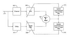
- FIG. 3illustrates a communications system 301 of one embodiment of the present invention.
- communications system 301uses a TEQ filter 305 (e.g., finite impulse response (FIR) filter) to shorten a continuous time channel impulse response associated with a channel 303 .
- Communications system 301further includes a target filter 309 , an error estimator 307 , an update TEQ processor 313 , an update target processor 315 , and a delay element 311 .
- TEQ filter 305has an impulse response which is spectrally flat in that the impulse response avoids significant ripple in the useful band.
- Data 317(for example, one or more information symbols) is communicated to channel 303 and the resulting signal is processed by TEQ filter 305 .
- channel 303may be any medium commonly used in communications systems.
- channel 303may be a twisted pair of wires, such as copper wires, or the like.
- Data that is the same as data 317is also applied to delay element 311 and filtered by target filter 309 .
- error estimator 307calculates the error between data filtered by TEQ filter 305 and data filtered by target filter 309 and generates error information.
- the error informationis communicated to update TEQ processor 313 and update target processor 315 . Based on the error information, update TEQ processor 313 and update target processor 315 adapt TEQ filter 305 and target filter 309 , respectively, in order to reduce the error, and more specifically, to reduce a function of that error.
- One embodiment of the present inventionuses an adaptive filter identification algorithm in order to reduce the error. This process is continued for any number of iterations in order to reduce the error. In this manner, channel 303 is effectively shortened, resulting in an equalized channel. In accordance with this embodiment of the present invention, convergence of the adaptive techniques allows the error to be decreased and approach (or equal to) zero.
- a function of the errormay be calculated using one or more methodologies including a quadratic error, a cubic error, an absolute error, or any other function of the error, and the like.
- One or more adaptive filter identification algorithmsmay be used, including least mean square (LMS), recursive least square (RLS), or the like.
- one or more taps of TEQ filter 305may be constrained during one or more iterations to any non-zero real number. Constraining a tap to a value keeps the tap value from changing.
- one or more taps of target filter 309may be constrained during one or more iterations to any non-zero real number.
- the central tap of TEQ filter 305 and/or target filter 309may be constrained to any non-zero real number. Simulation examples have shown that constraining the central tap of TEQ filter 305 to a constant value avoids significant ripple in the band of interest and thus improves the spectral flatness of TEQ filter 305 .
- update TEQ processor 313 and/or update target processor 315change the values of one or more taps of TEQ filter 305 and/or target filter 309 , respectively
- the specified tap(s) of TEQ filter 305 and/or target filter 309will remain constrained to the non-zero real number selected. In other words, the specified tap(s) of TEQ filter 305 and/or target filter 309 will not vary during operation.
- update TEQ processor 313 and update target processor 315may change the non-constrained values of the taps of TEQ filter 305 and/or target filter 309 , respectively.
- FIG. 4is a flowchart illustrating one method of the present invention of increasing the data rate of a communications system.
- the systemis initialized. Initialization includes zeroing (or otherwise setting) the tap values for TEQ filter 305 and target filter 309 . Also during initialization, an appropriate delay for target filter 309 may be selected. Those skilled in the art will appreciate that an appropriate delay for delay element 311 may be chosen to achieve a shortened channel 303 in CP+1 number of taps. An appropriate delay may be computed by estimating the delay introduced by the channel by using, for example, the auto-correlation function between the input and the output signals of the channel.
- one or more specified taps(e.g., the central tap) of TEQ filter 305 and/or target filter 309 may be constrained to a non-zero real number during initialization, where constraining a tap value keeps the value from changing during iterations.
- step 403data is obtained from channel 303 (step 403 ), and filtered by TEQ filter 305 (step 405 ).
- step 407the data is also delayed and filtered by target filter 309 in step 409 .
- the difference between the TEQ filtered data and the target filtered datai.e., the error, is calculated (step 411 ).
- the error(or a function of the error) between the output of TEQ filter 305 and the output of target filter 309 is calculated.
- step 413the error is communicated to update TEQ processor 313 , which calculates new tap values for TEQ filter 305 (except for constrained taps).
- the erroris also communicated to update target processor 315 , which calculates new tap values for target filter 309 .
- the new tap values calculated for target filter 309may vary in value from the new tap values calculated for TEQ filter 305 .
- the error between the TEQ filtered data and the target filtered datais reduced by updating the taps of TEQ filter 305 and target filter 309 by iterative feedback of the error calculation to TEQ filter 305 and target filter 309 . Such a feedback process continues reducing the error until the error reaches a predetermined tolerable level.
- one way to reduce the error between the TEQ filtered data and the target filtered datais to calculate the new tap values for TEQ filter 305 and target filter 309 using an adaptive filter identification algorithm, such as LMS, RLS, or the like. Steps 403 through 413 are repeated in order to reduce the error between the TEQ filtered data and the target filtered data to a predetermined level. Accordingly, there may be a number of iterations before achieving a predetermined error.
- adaptation of TEQ filter 305 and target filter 309may stop.
- communications system 301may continuously monitor TEQ filter 305 and target filter 309 , even when the predetermined error level is reached.
- reducing and ideally optimizing the error between the TEQ filtered data and the target filtered datawill adapt the convolution of channel 303 and TEQ filter 305 with target filter 309 .
- the TEQ filter design of the present inventionreduces the error between the TEQ filter and the target filter by calculating one or more tap values for both while constraining one or more taps of the TEQ filter and/or the target filter.
- the TEQ filter design of the present inventionbalances the shortening of a channel with spectral flatness of the TEQ filter to increase the data rate of the communications system.
Landscapes
- Engineering & Computer Science (AREA)
- Power Engineering (AREA)
- Computer Networks & Wireless Communication (AREA)
- Signal Processing (AREA)
- Cable Transmission Systems, Equalization Of Radio And Reduction Of Echo (AREA)
Abstract
Description
Claims (18)
Priority Applications (1)
| Application Number | Priority Date | Filing Date | Title |
|---|---|---|---|
| US09/665,784US6829296B1 (en) | 2000-09-20 | 2000-09-20 | Spectrally flat time domain equalizer and methods |
Applications Claiming Priority (1)
| Application Number | Priority Date | Filing Date | Title |
|---|---|---|---|
| US09/665,784US6829296B1 (en) | 2000-09-20 | 2000-09-20 | Spectrally flat time domain equalizer and methods |
Publications (1)
| Publication Number | Publication Date |
|---|---|
| US6829296B1true US6829296B1 (en) | 2004-12-07 |
Family
ID=33477210
Family Applications (1)
| Application Number | Title | Priority Date | Filing Date |
|---|---|---|---|
| US09/665,784Expired - Fee RelatedUS6829296B1 (en) | 2000-09-20 | 2000-09-20 | Spectrally flat time domain equalizer and methods |
Country Status (1)
| Country | Link |
|---|---|
| US (1) | US6829296B1 (en) |
Cited By (22)
| Publication number | Priority date | Publication date | Assignee | Title |
|---|---|---|---|---|
| US20020126741A1 (en)* | 2000-12-29 | 2002-09-12 | Motorola Inc. | Method and system for transmission and frequency domain equalization for wideband CDMA system |
| US20030210742A1 (en)* | 2002-03-18 | 2003-11-13 | Cornell Research Foundation, Inc. | Methods and system for equalizing data |
| US20050053127A1 (en)* | 2003-07-09 | 2005-03-10 | Muh-Tian Shiue | Equalizing device and method |
| WO2007073700A1 (en)* | 2005-12-29 | 2007-07-05 | Triductor Technology (Suzhou) Inc. | Time-domain equalizer |
| US20070297499A1 (en)* | 2006-06-21 | 2007-12-27 | Acorn Technologies, Inc. | Efficient channel shortening in communication systems |
| US20080187038A1 (en)* | 2007-02-02 | 2008-08-07 | Broadcom Corporation | Asymmetric multi-channel adaptive equalizer |
| US7505537B1 (en)* | 2003-03-25 | 2009-03-17 | Marvell International Ltd. | System and method for controlling gain and timing phase in a presence of a first least mean square filter using a second adaptive filter |
| US20100311412A1 (en)* | 2009-06-05 | 2010-12-09 | Picochip Designs Limited | Method and Device in a Communication Network |
| US20110069605A1 (en)* | 2009-09-21 | 2011-03-24 | Kennan Laudel | Coaxial network communication node and methods for communicating multimedia over a coaxial network with reduced-length cyclic prefixes |
| USRE43402E1 (en)* | 2001-01-25 | 2012-05-22 | Ninel Technology, Llc | Adaptive adjustment of time and frequency domain equalizers in communications systems |
| US8463312B2 (en) | 2009-06-05 | 2013-06-11 | Mindspeed Technologies U.K., Limited | Method and device in a communication network |
| US8559998B2 (en) | 2007-11-05 | 2013-10-15 | Mindspeed Technologies U.K., Limited | Power control |
| US8712469B2 (en) | 2011-05-16 | 2014-04-29 | Mindspeed Technologies U.K., Limited | Accessing a base station |
| US8779847B1 (en) | 2011-07-13 | 2014-07-15 | Marvell International Ltd. | Systems and methods for finite impulse response adaptation for gain and phase control |
| US8798630B2 (en) | 2009-10-05 | 2014-08-05 | Intel Corporation | Femtocell base station |
| US8849340B2 (en) | 2009-05-07 | 2014-09-30 | Intel Corporation | Methods and devices for reducing interference in an uplink |
| US8904148B2 (en) | 2000-12-19 | 2014-12-02 | Intel Corporation | Processor architecture with switch matrices for transferring data along buses |
| US9042434B2 (en) | 2011-04-05 | 2015-05-26 | Intel Corporation | Filter |
| US9042436B2 (en) | 2007-02-02 | 2015-05-26 | Broadcom Corporation | Asymmetric multi-channel adaptive equalizer |
| US9107136B2 (en) | 2010-08-16 | 2015-08-11 | Intel Corporation | Femtocell access control |
| US9503291B1 (en)* | 2015-11-04 | 2016-11-22 | Global Unichip Corporation | Method and apparatus for discrete multitone transmission |
| US10856302B2 (en) | 2011-04-05 | 2020-12-01 | Intel Corporation | Multimode base station |
Citations (7)
| Publication number | Priority date | Publication date | Assignee | Title |
|---|---|---|---|---|
| US5285474A (en) | 1992-06-12 | 1994-02-08 | The Board Of Trustees Of The Leland Stanford, Junior University | Method for equalizing a multicarrier signal in a multicarrier communication system |
| US5461640A (en)* | 1994-06-03 | 1995-10-24 | Texas Instruments Incorporated | Method and system for optimizing an equalizer in a data transmission system |
| US5870432A (en)* | 1995-10-11 | 1999-02-09 | Alcatel N. V. | Method for transmission line impulse response equalization and a device to perform this method |
| US6404806B1 (en)* | 1998-12-31 | 2002-06-11 | Nortel Networks Limited | Method and apparatus for time-domain equalization in FDM-based discrete multi-tone modems |
| US6526105B1 (en)* | 1998-05-29 | 2003-02-25 | Tellabs, Operations, Inc. | Time domain equalization for discrete multi-tone systems |
| US20030103576A1 (en)* | 2000-10-20 | 2003-06-05 | Samsung Electronics Co., Ltd. | Encoding/decoding apparatus and method for orientation interpolator node data |
| US6674795B1 (en)* | 2000-04-04 | 2004-01-06 | Nortel Networks Limited | System, device and method for time-domain equalizer training using an auto-regressive moving average model |
- 2000
- 2000-09-20USUS09/665,784patent/US6829296B1/ennot_activeExpired - Fee Related
Patent Citations (7)
| Publication number | Priority date | Publication date | Assignee | Title |
|---|---|---|---|---|
| US5285474A (en) | 1992-06-12 | 1994-02-08 | The Board Of Trustees Of The Leland Stanford, Junior University | Method for equalizing a multicarrier signal in a multicarrier communication system |
| US5461640A (en)* | 1994-06-03 | 1995-10-24 | Texas Instruments Incorporated | Method and system for optimizing an equalizer in a data transmission system |
| US5870432A (en)* | 1995-10-11 | 1999-02-09 | Alcatel N. V. | Method for transmission line impulse response equalization and a device to perform this method |
| US6526105B1 (en)* | 1998-05-29 | 2003-02-25 | Tellabs, Operations, Inc. | Time domain equalization for discrete multi-tone systems |
| US6404806B1 (en)* | 1998-12-31 | 2002-06-11 | Nortel Networks Limited | Method and apparatus for time-domain equalization in FDM-based discrete multi-tone modems |
| US6674795B1 (en)* | 2000-04-04 | 2004-01-06 | Nortel Networks Limited | System, device and method for time-domain equalizer training using an auto-regressive moving average model |
| US20030103576A1 (en)* | 2000-10-20 | 2003-06-05 | Samsung Electronics Co., Ltd. | Encoding/decoding apparatus and method for orientation interpolator node data |
Non-Patent Citations (5)
| Title |
|---|
| "Time-Domain Channel Equalizer Design Using the Inverse Power Method", by Wei-min Chiu, Wei Kang Tsai, Thomas C. Liau, University of California, Irvine and Markos Troulis, Conexant Systems, Inc. |
| "Time-Domain Equalizer Training for ADSL", by Mohammed Nafie and Alan Gatherer, Texas Instruments, Dallas, USA, IEEE, 1997. |
| Al-Dhahir et al., "Optimum Finite-Length Equalization for Multicarrier Transceivers,"IEEE Transactions on Communications, vol. 44, No. 1(Jan. 1996), pp. 56-64. |
| Chow et al., "Equalizer Training Algorithms for Multicarrier Modulation Systems," IEEE, (Feb. 1993), pp. 761-765. |
| Melsa et al., "Impulse Response Shortening for Discrete Multitone Transceivers," IEEE Transactions on Communications, vol. 44, No. 12(Dec. 1996), pp. 1662-1672. |
Cited By (51)
| Publication number | Priority date | Publication date | Assignee | Title |
|---|---|---|---|---|
| US8904148B2 (en) | 2000-12-19 | 2014-12-02 | Intel Corporation | Processor architecture with switch matrices for transferring data along buses |
| US7218666B2 (en)* | 2000-12-29 | 2007-05-15 | Motorola, Inc. | Method and system for transmission and frequency domain equalization for wideband CDMA system |
| US20020126741A1 (en)* | 2000-12-29 | 2002-09-12 | Motorola Inc. | Method and system for transmission and frequency domain equalization for wideband CDMA system |
| USRE43402E1 (en)* | 2001-01-25 | 2012-05-22 | Ninel Technology, Llc | Adaptive adjustment of time and frequency domain equalizers in communications systems |
| US7305028B2 (en)* | 2002-03-18 | 2007-12-04 | Cornell Research Foundation, Inc. | Methods and system for equalizing data |
| US20030210742A1 (en)* | 2002-03-18 | 2003-11-13 | Cornell Research Foundation, Inc. | Methods and system for equalizing data |
| US9641359B1 (en) | 2003-03-25 | 2017-05-02 | Marvell International Ltd. | Apparatus and method for accounting for gain and phase error introduced by a first filter by adjusting coefficients of a second filter |
| US8279984B1 (en) | 2003-03-25 | 2012-10-02 | Marvell International, Ltd. | System and method for controlling gain and timing phase in a presence of a first least mean square filter using a second adaptive filter |
| US8081720B1 (en) | 2003-03-25 | 2011-12-20 | Marvell International Ltd. | System and method for controlling gain and timing phase in a presence of a first least mean square filter using a second adaptive filter |
| US8599975B1 (en) | 2003-03-25 | 2013-12-03 | Marvell International Ltd. | System and method for controlling gain and timing phase in a presence of a first least mean square filter using a second adaptive filter |
| US7505537B1 (en)* | 2003-03-25 | 2009-03-17 | Marvell International Ltd. | System and method for controlling gain and timing phase in a presence of a first least mean square filter using a second adaptive filter |
| US9319024B1 (en) | 2003-03-25 | 2016-04-19 | Marvell International Ltd. | Apparatus and method for accounting for gain and timing phase error, not accounted for by coefficients of a first filter, via coefficients of a second filter |
| US10027515B1 (en) | 2003-03-25 | 2018-07-17 | Marvell International Ltd. | Apparatus and method for introducing gain and phase offset via a second filter due to constraint of coefficients of a first filter |
| US20050053127A1 (en)* | 2003-07-09 | 2005-03-10 | Muh-Tian Shiue | Equalizing device and method |
| US9413567B1 (en) | 2004-02-27 | 2016-08-09 | Marvell International Ltd. | Systems and methods for finite impulse response adaptation for gain and phase control |
| CN101422004B (en)* | 2005-12-29 | 2013-01-02 | 创达特(苏州)科技有限责任公司 | Time-domain equalizer |
| US20090290629A1 (en)* | 2005-12-29 | 2009-11-26 | Yaolong Tan | Time-Domain Equalizer |
| US8111740B2 (en) | 2005-12-29 | 2012-02-07 | Triductor Technology (Suzhou) Inc. | Time-domain equalizer |
| WO2007073700A1 (en)* | 2005-12-29 | 2007-07-05 | Triductor Technology (Suzhou) Inc. | Time-domain equalizer |
| US7639738B2 (en)* | 2006-06-21 | 2009-12-29 | Acorn Technologies, Inc. | Efficient channel shortening in communication systems |
| US20070297499A1 (en)* | 2006-06-21 | 2007-12-27 | Acorn Technologies, Inc. | Efficient channel shortening in communication systems |
| US20080187038A1 (en)* | 2007-02-02 | 2008-08-07 | Broadcom Corporation | Asymmetric multi-channel adaptive equalizer |
| US8160127B2 (en) | 2007-02-02 | 2012-04-17 | Broadcom Corporation | Asymmetric multi-channel adaptive equalizer |
| US9042436B2 (en) | 2007-02-02 | 2015-05-26 | Broadcom Corporation | Asymmetric multi-channel adaptive equalizer |
| US20110200091A1 (en)* | 2007-02-02 | 2011-08-18 | Broadcom Corporation | Asymmetric Multi-Channel Adaptive Equalizer |
| US7885323B2 (en)* | 2007-02-02 | 2011-02-08 | Broadcom Corporation | Asymmetric multi-channel adaptive equalizer |
| US8437387B2 (en) | 2007-02-02 | 2013-05-07 | Broadcom Corporation | Asymmetric multi-channel adaptive equalizer |
| US8559998B2 (en) | 2007-11-05 | 2013-10-15 | Mindspeed Technologies U.K., Limited | Power control |
| US8849340B2 (en) | 2009-05-07 | 2014-09-30 | Intel Corporation | Methods and devices for reducing interference in an uplink |
| US20100311412A1 (en)* | 2009-06-05 | 2010-12-09 | Picochip Designs Limited | Method and Device in a Communication Network |
| US8385836B2 (en)* | 2009-06-05 | 2013-02-26 | Mindspeed Technologies U.K., Limited | Method and device in a communication network |
| US8463312B2 (en) | 2009-06-05 | 2013-06-11 | Mindspeed Technologies U.K., Limited | Method and device in a communication network |
| US9807771B2 (en) | 2009-06-05 | 2017-10-31 | Intel Corporation | Method and device in a communication network |
| US8892154B2 (en) | 2009-06-05 | 2014-11-18 | Intel Corporation | Method and device in a communication network |
| US8862076B2 (en)* | 2009-06-05 | 2014-10-14 | Intel Corporation | Method and device in a communication network |
| US8121023B2 (en) | 2009-09-21 | 2012-02-21 | Intel Corporation | Coaxial network communication node and methods for communicating multimedia over a coaxial network with reduced-length cyclic prefixes |
| CN102025679A (en)* | 2009-09-21 | 2011-04-20 | 英特尔公司 | Communication node and method for transmitting multimedia via coaxial network with shortened cyclic prefix |
| US20110069605A1 (en)* | 2009-09-21 | 2011-03-24 | Kennan Laudel | Coaxial network communication node and methods for communicating multimedia over a coaxial network with reduced-length cyclic prefixes |
| US8345550B2 (en) | 2009-09-21 | 2013-01-01 | Intel Corporation | Coaxial network communication node and methods for communicating within a MoCA network with reduced-length cyclic prefixes |
| WO2011034664A2 (en) | 2009-09-21 | 2011-03-24 | Intel Corporation | Coaxial network communication node and methods for communicating multimedia over a coaxial network with reduced-length cyclic prefixes |
| US8593934B2 (en) | 2009-09-21 | 2013-11-26 | Intel Corporation | Communication device and method for packet-based OFDM communications with differing length cyclic prefixes |
| WO2011034664A3 (en)* | 2009-09-21 | 2011-05-12 | Intel Corporation | Coaxial network communication node and methods for communicating multimedia over a coaxial network with reduced-length cyclic prefixes |
| US9191169B2 (en) | 2009-09-21 | 2015-11-17 | Intel Corporation | Communication device and method for packet-based OFDM communications with differing length cyclic prefixes |
| CN102025679B (en)* | 2009-09-21 | 2015-11-25 | 英特尔公司 | Communication node and method for transmitting multimedia via coaxial network with shortened cyclic prefix |
| US8798630B2 (en) | 2009-10-05 | 2014-08-05 | Intel Corporation | Femtocell base station |
| US9107136B2 (en) | 2010-08-16 | 2015-08-11 | Intel Corporation | Femtocell access control |
| US9042434B2 (en) | 2011-04-05 | 2015-05-26 | Intel Corporation | Filter |
| US10856302B2 (en) | 2011-04-05 | 2020-12-01 | Intel Corporation | Multimode base station |
| US8712469B2 (en) | 2011-05-16 | 2014-04-29 | Mindspeed Technologies U.K., Limited | Accessing a base station |
| US8779847B1 (en) | 2011-07-13 | 2014-07-15 | Marvell International Ltd. | Systems and methods for finite impulse response adaptation for gain and phase control |
| US9503291B1 (en)* | 2015-11-04 | 2016-11-22 | Global Unichip Corporation | Method and apparatus for discrete multitone transmission |
Similar Documents
| Publication | Publication Date | Title |
|---|---|---|
| US6829296B1 (en) | Spectrally flat time domain equalizer and methods | |
| JP4588168B2 (en) | Fast training of equalizers in DMT systems | |
| EP1068704B1 (en) | Filter for impulse response shortening, with additional spectral constraints, for multicarrier transmission | |
| JP3751203B2 (en) | Kalman equalization in multi-carrier receivers | |
| US8767812B2 (en) | Systems and methods for frequency domain realization of non-integer fractionally spaced time domain equalization | |
| US6320901B1 (en) | Method for fast off-line training for discrete multitone transmissions | |
| JP2008532354A (en) | Wireless communication apparatus and associated method for providing improved block equalization | |
| JP2008530906A (en) | Wireless communication apparatus and associated method for performing block equalization based on predicted values of past, present and / or future autocorrelation matrices | |
| US7224725B2 (en) | Method for determining coefficients of an equalizer and apparatus for determining the same | |
| EP1579649A1 (en) | Method and arrangement for filter bank based signal processing | |
| US20090074104A1 (en) | Subdimensional single-carrier modulation | |
| EP1028563A2 (en) | Time-domain equalisation for discrete multi-tone transceiver | |
| JP2000022600A (en) | Training method for time domain equalizer and digital data transmission device | |
| US6563841B1 (en) | Per-bin adaptive equalization in windowed DMT-type modem receiver | |
| US6879639B1 (en) | Data transceiver with filtering and precoding | |
| US20030118094A1 (en) | Mixed time and frequency domains equalization algorithm for ADSL systems | |
| JP2002208909A (en) | Method and device for removing communication system noise trouble | |
| US7489734B2 (en) | Equalization in radio receiver | |
| US6647076B1 (en) | Method of compensating for interference in a signal generated by discrete multitone modulation, and circuit configuration for carrying out the method. | |
| EP1257105A2 (en) | Equalization for ADSL using a mixed time domain and frequency domain approach | |
| US9014250B2 (en) | Filter for impulse response shortening with additional spectral constraints for multicarrier transmission | |
| KR100398138B1 (en) | Channel Impulse Response Shortening Method in the data transmission and reception | |
| EP1434401A1 (en) | Time domain equalization using frequency domain operations | |
| Alhava | Time-domain equalizer for filter bank-based multicarrier communications | |
| KR100299767B1 (en) | Channel shortening equalizer |
Legal Events
| Date | Code | Title | Description |
|---|---|---|---|
| AS | Assignment | Owner name:CONEXANT SYSTEMS, INC., CALIFORNIA Free format text:ASSIGNMENT OF ASSIGNORS INTEREST;ASSIGNORS:TROULIS, MARKOS G.;PETSALIS, EVANGELOS;ZHANG, XUMING;REEL/FRAME:011106/0730 Effective date:20000919 | |
| AS | Assignment | Owner name:MINDSPEED TECHNOLOGIES, INC., CALIFORNIA Free format text:ASSIGNMENT OF ASSIGNORS INTEREST;ASSIGNOR:CONEXANT SYSTEMS, INC.;REEL/FRAME:014568/0275 Effective date:20030627 | |
| AS | Assignment | Owner name:CONEXANT SYSTEMS, INC., CALIFORNIA Free format text:SECURITY AGREEMENT;ASSIGNOR:MINDSPEED TECHNOLOGIES, INC.;REEL/FRAME:014546/0305 Effective date:20030930 | |
| FEPP | Fee payment procedure | Free format text:PAYOR NUMBER ASSIGNED (ORIGINAL EVENT CODE: ASPN); ENTITY STATUS OF PATENT OWNER: LARGE ENTITY | |
| CC | Certificate of correction | ||
| FPAY | Fee payment | Year of fee payment:4 | |
| FEPP | Fee payment procedure | Free format text:PAYER NUMBER DE-ASSIGNED (ORIGINAL EVENT CODE: RMPN); ENTITY STATUS OF PATENT OWNER: LARGE ENTITY Free format text:PAYOR NUMBER ASSIGNED (ORIGINAL EVENT CODE: ASPN); ENTITY STATUS OF PATENT OWNER: LARGE ENTITY | |
| FPAY | Fee payment | Year of fee payment:8 | |
| AS | Assignment | Owner name:MINDSPEED TECHNOLOGIES, INC, CALIFORNIA Free format text:RELEASE OF SECURITY INTEREST;ASSIGNOR:CONEXANT SYSTEMS, INC;REEL/FRAME:031494/0937 Effective date:20041208 | |
| AS | Assignment | Owner name:JPMORGAN CHASE BANK, N.A., AS ADMINISTRATIVE AGENT Free format text:SECURITY INTEREST;ASSIGNOR:MINDSPEED TECHNOLOGIES, INC.;REEL/FRAME:032495/0177 Effective date:20140318 | |
| AS | Assignment | Owner name:MINDSPEED TECHNOLOGIES, INC., CALIFORNIA Free format text:RELEASE BY SECURED PARTY;ASSIGNOR:JPMORGAN CHASE BANK, N.A.;REEL/FRAME:032861/0617 Effective date:20140508 Owner name:GOLDMAN SACHS BANK USA, NEW YORK Free format text:SECURITY INTEREST;ASSIGNORS:M/A-COM TECHNOLOGY SOLUTIONS HOLDINGS, INC.;MINDSPEED TECHNOLOGIES, INC.;BROOKTREE CORPORATION;REEL/FRAME:032859/0374 Effective date:20140508 | |
| REMI | Maintenance fee reminder mailed | ||
| LAPS | Lapse for failure to pay maintenance fees | ||
| STCH | Information on status: patent discontinuation | Free format text:PATENT EXPIRED DUE TO NONPAYMENT OF MAINTENANCE FEES UNDER 37 CFR 1.362 | |
| FP | Lapsed due to failure to pay maintenance fee | Effective date:20161207 |