US6827710B1 - Multiple lumen access device - Google Patents
Multiple lumen access deviceDownload PDFInfo
- Publication number
- US6827710B1 US6827710B1US09/329,002US32900299AUS6827710B1US 6827710 B1US6827710 B1US 6827710B1US 32900299 AUS32900299 AUS 32900299AUS 6827710 B1US6827710 B1US 6827710B1
- Authority
- US
- United States
- Prior art keywords
- lumen
- auxiliary
- valve
- junction housing
- main channel
- Prior art date
- Legal status (The legal status is an assumption and is not a legal conclusion. Google has not performed a legal analysis and makes no representation as to the accuracy of the status listed.)
- Expired - Lifetime
Links
- 238000007789sealingMethods0.000claimsabstractdescription9
- 239000012530fluidSubstances0.000claimsdescription90
- 238000001802infusionMethods0.000claimsdescription53
- 239000000463materialSubstances0.000claimsdescription48
- 238000004891communicationMethods0.000claimsdescription34
- 238000000034methodMethods0.000claimsdescription34
- 238000003780insertionMethods0.000claimsdescription14
- 230000037431insertionEffects0.000claimsdescription14
- 238000011109contaminationMethods0.000claimsdescription9
- 125000006850spacer groupChemical group0.000claimsdescription9
- 230000013011matingEffects0.000claimsdescription7
- 210000005166vasculatureAnatomy0.000claimsdescription7
- 238000005452bendingMethods0.000claimsdescription4
- 239000008155medical solutionSubstances0.000claimsdescription4
- 230000004044responseEffects0.000claimsdescription4
- 230000008878couplingEffects0.000claimsdescription3
- 238000010168coupling processMethods0.000claimsdescription3
- 238000005859coupling reactionMethods0.000claimsdescription3
- 230000000717retained effectEffects0.000abstract1
- 238000001125extrusionMethods0.000description11
- 238000000926separation methodMethods0.000description10
- 230000008901benefitEffects0.000description9
- 239000007788liquidSubstances0.000description9
- 230000004888barrier functionEffects0.000description8
- 239000007787solidSubstances0.000description7
- 238000013461designMethods0.000description6
- 230000006870functionEffects0.000description6
- 230000001965increasing effectEffects0.000description6
- 238000004519manufacturing processMethods0.000description5
- 210000003462veinAnatomy0.000description5
- 239000003814drugSubstances0.000description4
- 239000013013elastic materialSubstances0.000description4
- 230000023597hemostasisEffects0.000description4
- -1polyethylenePolymers0.000description4
- 229920002635polyurethanePolymers0.000description4
- 239000004814polyurethaneSubstances0.000description4
- 238000001356surgical procedureMethods0.000description4
- 239000008280bloodSubstances0.000description3
- 210000004369bloodAnatomy0.000description3
- 230000007423decreaseEffects0.000description3
- 238000002405diagnostic procedureMethods0.000description3
- 239000003978infusion fluidSubstances0.000description3
- 238000012544monitoring processMethods0.000description3
- 238000000465mouldingMethods0.000description3
- 229920000642polymerPolymers0.000description3
- 230000001225therapeutic effectEffects0.000description3
- 238000011282treatmentMethods0.000description3
- 239000004677NylonSubstances0.000description2
- 239000004698PolyethyleneSubstances0.000description2
- 239000004743PolypropyleneSubstances0.000description2
- 230000015572biosynthetic processEffects0.000description2
- 230000007246mechanismEffects0.000description2
- 229920001778nylonPolymers0.000description2
- 229920000573polyethylenePolymers0.000description2
- 239000002861polymer materialSubstances0.000description2
- 229920001155polypropylenePolymers0.000description2
- 229920001296polysiloxanePolymers0.000description2
- 239000012858resilient materialSubstances0.000description2
- 230000007704transitionEffects0.000description2
- 235000004035Cryptotaenia japonicaNutrition0.000description1
- 208000012266Needlestick injuryDiseases0.000description1
- 239000004721Polyphenylene oxideSubstances0.000description1
- 208000007536ThrombosisDiseases0.000description1
- 102000007641Trefoil FactorsHuman genes0.000description1
- 235000015724Trifolium pratenseNutrition0.000description1
- 206010052428WoundDiseases0.000description1
- NIXOWILDQLNWCW-UHFFFAOYSA-Nacrylic acid groupChemical groupC(C=C)(=O)ONIXOWILDQLNWCW-UHFFFAOYSA-N0.000description1
- 230000006978adaptationEffects0.000description1
- 239000000853adhesiveSubstances0.000description1
- 230000001070adhesive effectEffects0.000description1
- 238000002399angioplastyMethods0.000description1
- 230000036772blood pressureEffects0.000description1
- DQXBYHZEEUGOBF-UHFFFAOYSA-Nbut-3-enoic acid;etheneChemical compoundC=C.OC(=O)CC=CDQXBYHZEEUGOBF-UHFFFAOYSA-N0.000description1
- 230000000747cardiac effectEffects0.000description1
- 230000008859changeEffects0.000description1
- 230000000295complement effectEffects0.000description1
- 230000008602contractionEffects0.000description1
- 229920001577copolymerPolymers0.000description1
- 238000013016dampingMethods0.000description1
- 238000005516engineering processMethods0.000description1
- 230000002708enhancing effectEffects0.000description1
- 239000005038ethylene vinyl acetateSubstances0.000description1
- 239000004811fluoropolymerSubstances0.000description1
- 229920002313fluoropolymerPolymers0.000description1
- 238000011010flushing procedureMethods0.000description1
- 230000005484gravityEffects0.000description1
- 238000002513implantationMethods0.000description1
- 230000006872improvementEffects0.000description1
- 238000000338in vitroMethods0.000description1
- 238000001727in vivoMethods0.000description1
- 239000007924injectionSubstances0.000description1
- 238000002347injectionMethods0.000description1
- 238000001746injection mouldingMethods0.000description1
- 230000003993interactionEffects0.000description1
- 230000007794irritationEffects0.000description1
- 230000007774longtermEffects0.000description1
- 239000000203mixtureSubstances0.000description1
- 238000012986modificationMethods0.000description1
- 230000004048modificationEffects0.000description1
- 239000012778molding materialSubstances0.000description1
- 210000000056organAnatomy0.000description1
- 229920001200poly(ethylene-vinyl acetate)Polymers0.000description1
- 229920002492poly(sulfone)Polymers0.000description1
- 229920000728polyesterPolymers0.000description1
- 229920000570polyetherPolymers0.000description1
- 229920000098polyolefinPolymers0.000description1
- 229920000915polyvinyl chloridePolymers0.000description1
- 239000004800polyvinyl chlorideSubstances0.000description1
- 230000008569processEffects0.000description1
- 238000011084recoveryMethods0.000description1
- 238000005070samplingMethods0.000description1
- 239000007779soft materialSubstances0.000description1
- 230000000153supplemental effectEffects0.000description1
- 229920003051synthetic elastomerPolymers0.000description1
- 239000005061synthetic rubberSubstances0.000description1
- 239000012815thermoplastic materialSubstances0.000description1
- 238000002054transplantationMethods0.000description1
- 238000003466weldingMethods0.000description1
Images


Classifications
- A—HUMAN NECESSITIES
- A61—MEDICAL OR VETERINARY SCIENCE; HYGIENE
- A61M—DEVICES FOR INTRODUCING MEDIA INTO, OR ONTO, THE BODY; DEVICES FOR TRANSDUCING BODY MEDIA OR FOR TAKING MEDIA FROM THE BODY; DEVICES FOR PRODUCING OR ENDING SLEEP OR STUPOR
- A61M25/00—Catheters; Hollow probes
- A61M25/0097—Catheters; Hollow probes characterised by the hub
- A—HUMAN NECESSITIES
- A61—MEDICAL OR VETERINARY SCIENCE; HYGIENE
- A61B—DIAGNOSIS; SURGERY; IDENTIFICATION
- A61B17/00—Surgical instruments, devices or methods
- A61B17/34—Trocars; Puncturing needles
- A61B17/3417—Details of tips or shafts, e.g. grooves, expandable, bendable; Multiple coaxial sliding cannulas, e.g. for dilating
- A61B17/3421—Cannulas
- A61B17/3439—Cannulas with means for changing the inner diameter of the cannula, e.g. expandable
- A—HUMAN NECESSITIES
- A61—MEDICAL OR VETERINARY SCIENCE; HYGIENE
- A61B—DIAGNOSIS; SURGERY; IDENTIFICATION
- A61B17/00—Surgical instruments, devices or methods
- A61B17/34—Trocars; Puncturing needles
- A61B17/3498—Valves therefor, e.g. flapper valves, slide valves
- A—HUMAN NECESSITIES
- A61—MEDICAL OR VETERINARY SCIENCE; HYGIENE
- A61B—DIAGNOSIS; SURGERY; IDENTIFICATION
- A61B17/00—Surgical instruments, devices or methods
- A61B17/34—Trocars; Puncturing needles
- A61B17/3417—Details of tips or shafts, e.g. grooves, expandable, bendable; Multiple coaxial sliding cannulas, e.g. for dilating
- A61B17/3421—Cannulas
- A61B2017/3445—Cannulas used as instrument channel for multiple instruments
- A—HUMAN NECESSITIES
- A61—MEDICAL OR VETERINARY SCIENCE; HYGIENE
- A61M—DEVICES FOR INTRODUCING MEDIA INTO, OR ONTO, THE BODY; DEVICES FOR TRANSDUCING BODY MEDIA OR FOR TAKING MEDIA FROM THE BODY; DEVICES FOR PRODUCING OR ENDING SLEEP OR STUPOR
- A61M25/00—Catheters; Hollow probes
- A61M25/0021—Catheters; Hollow probes characterised by the form of the tubing
- A61M25/0023—Catheters; Hollow probes characterised by the form of the tubing by the form of the lumen, e.g. cross-section, variable diameter
- A61M2025/0025—Catheters; Hollow probes characterised by the form of the tubing by the form of the lumen, e.g. cross-section, variable diameter having a collapsible lumen
- A—HUMAN NECESSITIES
- A61—MEDICAL OR VETERINARY SCIENCE; HYGIENE
- A61M—DEVICES FOR INTRODUCING MEDIA INTO, OR ONTO, THE BODY; DEVICES FOR TRANSDUCING BODY MEDIA OR FOR TAKING MEDIA FROM THE BODY; DEVICES FOR PRODUCING OR ENDING SLEEP OR STUPOR
- A61M25/00—Catheters; Hollow probes
- A61M25/0021—Catheters; Hollow probes characterised by the form of the tubing
- A61M25/0023—Catheters; Hollow probes characterised by the form of the tubing by the form of the lumen, e.g. cross-section, variable diameter
- A61M25/0026—Multi-lumen catheters with stationary elements
- A61M2025/0034—Multi-lumen catheters with stationary elements characterized by elements which are assembled, connected or fused, e.g. splittable tubes, outer sheaths creating lumina or separate cores
- A—HUMAN NECESSITIES
- A61—MEDICAL OR VETERINARY SCIENCE; HYGIENE
- A61M—DEVICES FOR INTRODUCING MEDIA INTO, OR ONTO, THE BODY; DEVICES FOR TRANSDUCING BODY MEDIA OR FOR TAKING MEDIA FROM THE BODY; DEVICES FOR PRODUCING OR ENDING SLEEP OR STUPOR
- A61M25/00—Catheters; Hollow probes
- A61M25/0021—Catheters; Hollow probes characterised by the form of the tubing
- A61M25/0023—Catheters; Hollow probes characterised by the form of the tubing by the form of the lumen, e.g. cross-section, variable diameter
- A61M25/0026—Multi-lumen catheters with stationary elements
- A61M2025/0035—Multi-lumen catheters with stationary elements characterized by a variable lumen cross-section by means of a resilient flexible septum or outer wall
- A—HUMAN NECESSITIES
- A61—MEDICAL OR VETERINARY SCIENCE; HYGIENE
- A61M—DEVICES FOR INTRODUCING MEDIA INTO, OR ONTO, THE BODY; DEVICES FOR TRANSDUCING BODY MEDIA OR FOR TAKING MEDIA FROM THE BODY; DEVICES FOR PRODUCING OR ENDING SLEEP OR STUPOR
- A61M25/00—Catheters; Hollow probes
- A61M25/0021—Catheters; Hollow probes characterised by the form of the tubing
- A61M25/0023—Catheters; Hollow probes characterised by the form of the tubing by the form of the lumen, e.g. cross-section, variable diameter
- A61M25/0026—Multi-lumen catheters with stationary elements
- A61M2025/0036—Multi-lumen catheters with stationary elements with more than four lumina
- A—HUMAN NECESSITIES
- A61—MEDICAL OR VETERINARY SCIENCE; HYGIENE
- A61M—DEVICES FOR INTRODUCING MEDIA INTO, OR ONTO, THE BODY; DEVICES FOR TRANSDUCING BODY MEDIA OR FOR TAKING MEDIA FROM THE BODY; DEVICES FOR PRODUCING OR ENDING SLEEP OR STUPOR
- A61M25/00—Catheters; Hollow probes
- A61M25/0021—Catheters; Hollow probes characterised by the form of the tubing
- A61M25/0023—Catheters; Hollow probes characterised by the form of the tubing by the form of the lumen, e.g. cross-section, variable diameter
- A61M25/0026—Multi-lumen catheters with stationary elements
- A61M25/0032—Multi-lumen catheters with stationary elements characterized by at least one unconventionally shaped lumen, e.g. polygons, ellipsoids, wedges or shapes comprising concave and convex parts
- A—HUMAN NECESSITIES
- A61—MEDICAL OR VETERINARY SCIENCE; HYGIENE
- A61M—DEVICES FOR INTRODUCING MEDIA INTO, OR ONTO, THE BODY; DEVICES FOR TRANSDUCING BODY MEDIA OR FOR TAKING MEDIA FROM THE BODY; DEVICES FOR PRODUCING OR ENDING SLEEP OR STUPOR
- A61M25/00—Catheters; Hollow probes
- A61M25/0067—Catheters; Hollow probes characterised by the distal end, e.g. tips
- A61M25/0074—Dynamic characteristics of the catheter tip, e.g. openable, closable, expandable or deformable
- A61M25/0075—Valve means
- A—HUMAN NECESSITIES
- A61—MEDICAL OR VETERINARY SCIENCE; HYGIENE
- A61M—DEVICES FOR INTRODUCING MEDIA INTO, OR ONTO, THE BODY; DEVICES FOR TRANSDUCING BODY MEDIA OR FOR TAKING MEDIA FROM THE BODY; DEVICES FOR PRODUCING OR ENDING SLEEP OR STUPOR
- A61M25/00—Catheters; Hollow probes
- A61M25/01—Introducing, guiding, advancing, emplacing or holding catheters
- A61M25/06—Body-piercing guide needles or the like
- A61M25/0662—Guide tubes
- A61M25/0668—Guide tubes splittable, tear apart
Definitions
- the present inventionrelates generally to medical devices which are used to provide access into the human body. More particularly, the present invention is directed to access devices which provide a single, relatively long-term, entry port into the body.
- the entry portis used by doctors and other medical professionals to selectively introduce a variety of medical implements and fluids into the body and for in vivo diagnostic testing and other treatment protocols.
- the first group of devicesincludes catheters which are designed to introduce therapeutic and/or diagnostic fluids into the blood stream.
- the second groupincludes devices commonly referred to as “introducers” which are designed to provide an intermediate term access port into the body through which various medical implements may be passed for therapeutic and/or diagnostic purposes.
- introducersAs a generalization, catheters are longer and more flexible than introducers.
- Central venous cathetersare relatively long tubular devices which have tapered distal tips which are designed for entry into central veins to provide a dedicated route of fluid infusion into the body.
- the original venous catheterswere single lumen devices which provided the ability to infuse a single liquid into the vein at one time.
- Multiple lumen cathetershave since been developed which allow simultaneous introduction of two or more liquids into the vein.
- the central venous pressure catheteris a type of common multiple lumen catheter which allows the simultaneous introduction and withdrawal of fluids as well as the capability of monitoring blood pressure and other vital parameters.
- the portion of the catheter which remains outside of the bodyhas been continually refined and redesigned to provide a low profile which increases comfort and reduces the awkwardness associated with a dedicated tube exiting the body.
- Introducersare substantially different from catheters in both design and purpose.
- An introduceris an access device which is intended to provide a dedicated access port into the body.
- Catheterson the other hand, are intended to be used to infuse or withdraw fluids from the body.
- Introducerstypically include a relatively short lumen through which various medical implements, including catheters, can be selectively introduced and removed from the body.
- An important feature of any introduceris the valve assembly.
- the valve assemblyprovides a constant seal between the blood stream and the in vitro environment as medical implements are introduced and withdrawn from the body.
- the valve assemblyis typically located outside of the body at the proximal end of the introducer. As a result, the proximal end of introducers has tended to be relatively bulky.
- many introducersinclude a side arm at the proximal end.
- the side armis connected to the lumen so that fluids can be introduced into the body simultaneously with the medical device.
- the introducer lumenis considered to be a “shared” lumen in that the lumen provides a common conduit for both medical implements and fluid pharmaceuticals or diagnostics.
- an improved access devicewhich is designed to provide selective introduction of medical implements into the body while simultaneously providing auxiliary access through dedicated multiple lumens.
- the present inventionis an improvement over existing introducers and other access devices in that multiple lumen access is provided through the introducer in addition to the shared lumen which is used for both medical implements and fluid pharmaceuticals or diagnostics.
- the improved access devicereduces the number of devices required to introduce multiple implements and fluids into the body during complex surgical and diagnostic procedures.
- the present inventiondesirably includes a multiple lumen access system for use in providing an entry port into the human body for selectively introducing medical implements therethrough and for providing simultaneous auxiliary access into the body.
- the systemincludes a multiple lumen access device comprising an outer tube which has a distal end for introduction into the body and a cross-sectional area.
- a device lumen through which medical implements may be passedis defined within the cross-sectional area of the outer tube, the device lumen having a distal end and a proximal end.
- At least one auxiliary lumenis defined within the cross-sectional area and separately from the device lumen, the auxiliary lumen having a distal end and proximal end.
- a device lumen valveis associated with the proximal end of the device lumen to provide sealing of the device lumen when medical implements are both present and absent from the device lumen.
- Such device lumen valvemay be separate and detachable or it may be integral with the system.
- a multiple lumen access systemmay also include a junction housing having a proximal end and a distal end to which the proximal end of the outer tube connects.
- the junction housingincludes a main channel in fluid communication with the device lumen and at least one auxiliary channel in fluid communication with the at least one auxiliary lumen, the main channel and auxiliary channel(s) diverging from the outer tube to be non-intersecting in the junction housing.
- the device lumen valveis provided as a part of the junction housing and is in fluid communication with the main channel.
- a device channelmay be formed in the junction housing at an angle with the main channel and terminating at an internal end in fluid communication with the main channel.
- the device lumen valvemay be positioned at an external end of the device channel so that medical devices may be inserted therethrough and enter the main channel at an angle.
- the main channeldesirably may continue from the distal end of the junction housing past the device lumen to an opening in the junction housing enabling introduction of fluids therethrough to the main channel.
- the device lumen valveis molded separately from the junction housing of a material more rigid than the junction housing and is assembled with the multiple lumen access device by insertion in a cavity formed in the junction housing.
- the main channel and auxiliary channel(s) of the junction housingmay be oriented substantially coplanar so that the junction housing is substantially flat, the system further including an extension tube extending from the proximal end of the junction housing and in fluid communication with the main channel wherein the device lumen valve is connected to the extension tube to therefore be in fluid communication with the main channel.
- a side port in the device lumen valvemay be provided enabling infusion of fluids to the extension tube and main channel.
- mating threaded connectorsmay be included between the device lumen valve and the extension tube enabling easy removal of the device lumen valve.
- Any appropriate connectorfor example a luer connector, may be provided on the device lumen valve, and the system may also include an infusion syringe having a mating luer connector.
- a multiple lumen access devicemay be provided with a multi-lumen sheath, a junction housing coupled to the multi-lumen sheath and a strain relief insert coupled to the junction housing.
- the strain relief insertis formed of a soft bendable material capable of flexing to prevent multi-lumen sheath from kinking at the sheath/junction housing coupling.
- the multiple lumen access deviceis formed by coupling a single lumen catheter to a junction housing having a main channel and at least one auxiliary channel through a multi-function adapter.
- the present inventionis directed to a multiple lumen access device including an outer tube which has a distal end for introduction into the body and a proximal end which remains outside of the body.
- the outer tubemay have an exterior surface and an interior surface, the interior surface defining an access passageway which has a cross-sectional area which may vary at different locations between the distal and proximal ends of the outer tube.
- One or more inner wallsare located within the access passageway.
- the inner wallmay form an inner tube that surrounds a device lumen through which medical implements may be inserted into the body.
- At least one auxiliary lumenis located between the exterior surface of the inner wall and the interior surface of the outer tube.
- two or more auxiliary passagewaysdefined by the interior surface of the outer tube and the exterior surface of the inner walls.
- the provision of two or more auxiliary passagewaysallows introduction of additional diagnostics or pharmaceutical liquids simultaneously with introduction of a medical implement through the device lumen.
- Embodiments of the present inventionare also described wherein a single auxiliary lumen is provided.
- the inner wallsare sufficiently flexible to be movable from a relaxed position to expanded or contracted positions.
- the device lumenhas a first cross-sectional area in the relaxed position, and in the expanded or contracted positions has cross-sectional areas which are greater than or less than the first cross-sectional area, and less than the cross-sectional area of the access passageway.
- the flexibility of the inner wallsis advantageous in that it allows the insertion of a variety of medical implements having different cross-sectional areas. This flexibility allows the cross-sectional areas and resultant potential fluid flow rate for the auxiliary lumens and the device lumen to be controlled as desired and maximized within the confines of the access passageway.
- spacer ribsare provided, for example, on the interior surface of the outer tube.
- the spacer ribsare located within the auxiliary lumens to prevent complete closure of the lumens during insertion of relatively large medical implements into the device lumen.
- the spacer ribs located on the surface of the inner wallinsure that there is a passageway around devices located within the device lumen.
- An alternative multiple lumen access device of the present inventioncomprises a tubular single lumen sheath having at least one infusion port and an elongated implement sized to fit coaxially within the single lumen sheath and form multiple independent lumens, and when at least one of the lumens is in fluid communication with the infusion port.
- the elongated implementmay be formed from a sufficiently flexible material so that at least one lumen formed by the sheath and the implement has flexible walls movable from a relaxed to a flexed positions.
- Another alternative multiple lumen access devicecomprises a multi-lumen catheter having a main lumen tube, at least one side lumen tube connected in a side-by-side fashion with the main lumen tube and being peelable from the main lumen to form sidearms, and a hub connected to the main lumen tube and side lumen tube for fluid delivery or passage of a medical device therethrough.
- the present inventionis also directed to a method for introducing medical devices into the body through a single entry port while allowing simultaneous introduction of other devices, implements or fluids through the use of the multiple lumen access device of the present invention.
- the methodincludes the steps of providing a multiple lumen access device in accordance with the present invention having at least one flexible wall; introducing the multiple lumen access device into the body with the distal ends of the device lumen and the auxiliary lumen being positioned within a vasculature of the body; and flowing a medical solution through the auxiliary lumen to move the flexible wall from the relaxed position to a flexed position.
- the methodincludes the steps of providing a tubular single lumen sheath having proximal and distal ends, at least one infusion port being provided on the proximal end of the sheath; providing an elongated implement sized to fit coaxially within the single lumen sheath, at least one of the lumens being in fluid communication with the infusion port; inserting the elongated implement into the single lumen sheath to form multiple independent lumens therein; and flowing a medical solution through one or more of the multiple independent lumens.
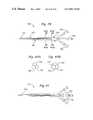
- FIG. 1is a perspective view of an exemplary preferred multiple lumen access device in accordance with the present invention.
- FIG. 2is a sectional view of FIG. 1 taken in the 2 — 2 plane of FIG. 1 .
- FIG. 3Ais a sectional view taken in the same 2 — 2 plane of FIG. 1 which shows a relatively small diameter medical device located within the device lumen.
- FIG. 3Bis a sectional view taken in the same 2 — 2 plane of FIG. 1 showing a relatively large diameter medical implement located within the device lumen.
- FIG. 4is a sectional view of FIG. 1 taken in the 4 — 4 plane.
- FIG. 5is a sectional view of FIG. 1 taken in the 5 — 5 plane.
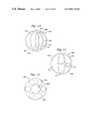
- FIG. 6is a perspective view of a preferred exemplary embodiment in accordance with the present invention.
- FIG. 7is a sectional view of FIG. 6 taken in the 7 — 7 plane.
- FIG. 8is a sectional view of FIG. 6 taken in the 8 — 8 plane.
- FIG. 9is a sectional view of a preferred exemplary flexible inner wall showing the location of spacing ribs.
- FIG. 10is a sectional view of a preferred exemplary multiple lumen access device having a single auxiliary lumen.
- FIGS. 11A-Care sectional views of an exemplary multiple lumen access device showing a relatively small diameter medical implement located in a central device lumen and the inner walls in relaxed conditions ( 11 A), partially collapsed about the implement due to pressurization of side auxiliary lumens ( 11 B), and substantially completely collapsed about the implement ( 11 C).
- FIG. 11Dis a sectional view of an alternative multiple lumen access device having flexible walls made of a material different from the material of the outer tube of the multiple lumen access device.
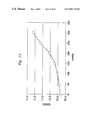
- FIG. 12is a graph illustrating an increase in the cross-sectional area (in gauge size) of an auxiliary lumen, such as in the cross-section shown in FIGS. 11A-11C, as the differential pressure between the auxiliary lumen and the device lumen changes.
- FIG. 13is a sectional view of an alternative multi-lumen sheath for use in the present invention having a device lumen on one side and two side-by-side auxiliary lumens.
- FIG. 14is a sectional view of an alternative multi-lumen sheath for use in the present invention having a device lumen on one side and two stacked auxiliary lumens.
- FIG. 15is a sectional view of an alternative multi-lumen sheath for use in the present invention having no flexible walls therein.
- FIG. 16is a perspective view of a further embodiment of a multiple lumen access device in accordance with the present invention.
- FIG. 17is a perspective sectional view of FIG. 16 taken in the 17 — 17 plane.
- FIG. 18Ais a perspective view of an extrusion die for making a sheath portion of the multiple lumen access device of the present invention.
- FIG. 18Bis an end view of a sheath portion of the multiple lumen access device as extruded from the die shown in FIG. 18 A.
- FIGS. 18C and 18Dare isolated views of inner extrusion molds of the die shown in FIG. 18A with exemplary dimensions for the sheath portion cross-section called out.
- FIG. 19is an enlarged perspective view of a junction housing of the device shown in FIG. 16 .
- FIG. 20is an enlarged perspective of the junction housing of FIG. 19 with a portion cut away on the longitudinal axis.
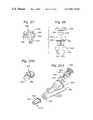
- FIG. 21is a perspective assembled view of a valve insert used in the junction housing of FIG. 16 .
- FIG. 22is an exploded perspective view of the valve insert of FIG. 21 .
- FIGS. 23A and 23Bare two perspective views of a multiple lumen access device similar to that shown in FIG. 16 .
- FIG. 24is an elevational view of the multiple lumen access device of FIGS. 23 A/ 23 B in place in the vasculature of a patient.
- FIG. 25Ais a perspective view of a junction housing of the device shown in FIGS. 23 and 24 showing a valve insert and strain relief insert both exploded therefrom.
- FIG. 25Bis a reversed perspective view of the strain relief insert adapted to be coupled to the junction housing in FIG. 25 A.
- FIG. 26is an exploded elevational view of the valve insert shown in FIG. 25 A.
- FIG. 27is a perspective view of a clamp portion for the valve insert of FIG. 26 .
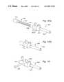
- FIGS. 28A and 28Bare perspective views of an adapter which mates with the valve inserts of FIGS. 21 or 26 .
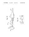
- FIG. 29is an elevational view of a multiple lumen access device in accordance with the present invention.
- FIG. 30is a plan view of the multiple lumen access device of FIG. 29 showing more details of an associated catheter system.
- FIG. 31is a perspective view of a proximal end of a low-profile junction housing of the device of FIG. 29 .
- FIG. 32is a plan view of an alternative multiple lumen access device with a low profile junction housing.
- FIG. 33is a detailed view of an alternative introducer valve assembly for use in the device of FIGS. 30 or 32 .
- FIG. 34is a plan view of an alternative multiple lumen access having a multi-lumen infusion catheter interfacing with a single lumen introducer.
- FIGS. 35A-35Dare schematic sectional views of sheath/lumen configurations for use in the multi-lumen infusion catheter of FIG. 34 .
- FIG. 36is a sectional view of a junction housing used in the device of FIG. 34 .
- FIG. 37is an elevational view of a further embodiment of a multi-lumen sheath for use in the device of FIG. 34 .
- FIG. 38is a sectional view of the multi-lumen sheath of FIG. 37 .
- FIG. 39is a plan view of a multiple lumen access device having a center tube and two side lumen tubes in accordance with the present invention.
- FIGS. 40A and 40Bare sectional views of a sheath of the multiple lumen access device of FIG. 39 taken along lines 40 A— 40 A and 40 B— 40 B, respectively.
- FIG. 41is an alternative multiple lumen access device with discrete tubes as in FIG. 39 and having a junction housing.
- FIG. 42Ais an exploded view of a multiple lumen access device having an introducer connected to a multi-lumen catheter by an adjustable adapter.
- FIG. 42Bis an assembled view of the multiple lumen access device of FIG. 42 A.
- FIG. 43Ais an exploded view of a multiple lumen access device having an introducer with infusion port connected to a multi-lumen catheter by an adapter.
- FIG. 43Bis an assembled view of the multiple lumen access device of FIG. 43 A.
- FIG. 44Ais an exploded view of a multiple lumen access device having an introducer with infusion port connected to a triple lumen junction housing and obturator by an adapter.
- FIG. 44Bis an assembled view of the multiple lumen access device of FIG. 44 A.
- FIG. 45Ais an exploded view of a multiple lumen access device having an introducer connected to triple lumen junction housing by a threaded adapter.
- FIG. 45Bis an assembled view of the multiple lumen access device of FIG. 45 A.
- FIG. 46Ais an exploded view of a multiple lumen access device having an introducer connected to triple lumen junction housing and elongated infusion tube by a threaded adapter.
- FIG. 46Bis an assembled view of the multiple lumen access device of FIG. 46 A.
- FIG. 47Ais an exploded view of a multiple lumen access device having an introducer with infusion port telescopically fitting within a larger introducer.
- FIG. 47Bis an assembled view of the multiple lumen access device of FIG. 47 A.
- FIG. 48Ais an exploded view of a multiple lumen access device with a multi-ribbed hollow obturator telescopically fitting within an introducer with infusion ports.
- FIG. 48Bis an assembled view of the multiple lumen access device of FIG. 48 A.
- FIG. 49is an assembled view of a multiple lumen access device similar to that shown in FIG. 48B with infusion ports formed on a hub of the multi-ribbed hollow obturator.
- FIG. 50Ais an exploded view of a multiple lumen access device with a multi-ribbed solid obturator telescopically fitting within an introducer with infusion ports.
- FIG. 50Bis an assembled view of the multiple lumen access device of FIG. 50 A.
- FIG. 51is an exploded sectional view of a multiple lumen access device with a multi-ribbed hollow obturator telescopically fitting within a tapered introducer with an infusion port.
- FIG. 52is an assembled view of the multiple lumen access device of FIG. 51 .
- FIG. 53is a sectional view of the obturator seen in FIG. 51 taken along line 53 — 53 .
- FIG. 54is a perspective view of a portion of the obturator seen in FIG. 51 .
- FIGS. 1-5An exemplary multiple lumen access device (MLAD) in accordance with the present invention is shown generally at 10 in FIGS. 1-5.
- the device 10includes an outer tube 12 which has a distal end 14 and a proximal end 16 .
- the outer tube 12has an exterior surface 18 and an interior surface 20 .
- the interior surface 20defines an access passageway or lumen 22 which has a cross-sectional area that may vary at different locations between the distal 14 and proximal 16 ends of the outer tube 12 .
- the outer tube 12may be tapered at the distal end 14 , if desired. As a result of the tapering of the outer tube 12 , the cross-sectional area will decrease accordingly.
- an inner tube 24is located within the access passageway 22 .
- the inner tube 24has a distal end and a proximal end which correspond to the distal end 14 and proximal end 16 of the outer tube 12 .
- the inner tube 24is formed by a wall surrounding a device lumen 30 , the wall having an exterior surface 26 and an interior surface 28 .
- the interior surface 28defines a device lumen 30 through which medical implements (such as catheters 32 and 34 shown in FIGS. 3A and 3B, respectively) may be inserted into the body.
- Catheter 34is also shown in position within the device lumen 30 in FIGS. 4 and 5.
- auxiliary lumens 36 and 48are located between the exterior surface 26 of the inner tube 24 and the interior surface 20 of the outer tube 12 .
- the auxiliary lumens 36 and 48each have a distal end and a proximal end which correspond generally to the distal and proximal ends of the outer tube 12 and inner tube 24 .
- the surfaces which define the auxiliary lumens 36 and 48correspond to portions of the interior surface of the outer tube and exterior surface of the inner tube.
- auxiliary lumen 36is defined or bordered by an interior surface 38 which corresponds to the interior surface 20 of the outer tube 12 and the exterior surface 26 of the inner tube 24 .
- the auxiliary lumen 36is defined by separation surfaces 40 and 42 which are formed by separation barriers 44 and 46 , respectively.
- a second auxiliary lumen 48is also formed or defined by the interior surface 20 of the outer tube 12 and the exterior surface 26 of the inner tube 24 . Accordingly, the interior surface 50 which defines the second auxiliary lumen 48 corresponds to these surfaces. In addition, the auxiliary lumen 48 is bordered by separation surfaces 52 and 54 formed by separation barriers 44 and 46 , respectively.
- the multiple lumen access device 10includes a junction housing 56 .
- the junction housing 56is connected to the proximal end 16 of the access lumen 12 .
- the housing 56includes infusion tubes 58 and 60 which are connected through the housing 56 to auxiliary lumens 36 and 48 , respectively.
- the infusion tubes 58 and 60include luer connectors 62 and 64 .
- Other conventional connection devicesmay be used.
- a third infusion tube 66is connected via the housing 56 to the device lumen 30 in order to provide a route for infusion of liquid into the device lumen 30 . It should be noted that the infusion tube 66 is not connected to the junction housing 56 at a right angle as is typically done in conventional introducer-type devices.
- the infusion tube 66extends from the housing 56 parallel to the other two infusion tubes 58 and 60 .
- This parallel orientation of the tubes 58 , 60 and 66allows housing 56 to be a low profile body which reduces the bulkiness of the proximal end of the device and increases its wearing comfort.
- a conventional locking device, such as luer lock 68is also provided at the proximal end of the infusion tube 66 .
- the housing 56includes a valve 70 through which various medical implements are inserted into the device lumen 30 .
- Valve 70includes a valve or gasket assembly which is designed to provide sealing of the device lumen 30 when medical implements are both present and absent from the device lumen 30 . Any of the known gasket arrangements and valve mechanisms used to provide sealing of introducers and related medical implement access devices are suitable.
- the multiple lumen access device 10is designed for use in combination with providing access to either the arterial or venous sides of the bloodstream.
- An opening 72(see FIG. 1 and FIG. 5) is provided towards the distal end of outer tube 12 .
- the opening 72is provided to allow exit of fluid from auxiliary lumen 48 which has been introduced through infusion tube 58 .
- an opening 74(shown in phantom in FIG. 1 and also shown in FIG. 4) is provided for allowing the fluid introduced through infusion tube 60 to exit auxiliary lumen 36 at the distal end of the outer tube 12 .
- the openings 72 and 74are preferably sized to avoid restricting fluid flow through the respective auxiliary lumens. Therefore, it is preferred that the openings 72 and 74 are each sized sufficiently large to be equal or greater than the maximum distended/expanded cross-sectional area of the corresponding auxiliary lumens 36 and 48 .
- this same principleapplies with regard to any number of auxiliary lumens each having a variable cross-section.
- the auxiliary lumenincreases, for example, from approximately 15 gauge to about 12 gauge, while in another embodiment the auxiliary lumen increases from approximately 18 gauge to about 14 gauge. Therefore, the openings 72 and 74 are each sized to be equivalent to or greater than 12 gauge or 14 gauge, respectively, to avoid restricting fluid flow through the respective auxiliary lumen. When other cross-section diameters of the auxiliary lumens are used, the size of the openings, such as 72 and 74 , are preferably sized accordingly.
- the inner tube 24must be sufficiently flexible to be stretchable between a relaxed position as shown in FIG. 3 A and various expanded positions as exemplified in FIG. 3 B.
- a catheter 32 having a diameter of 1.3 millimeter (4 French)is shown inserted within the device lumen 30 .
- the inner tube 24is in a relaxed position where the cross-sectional area of the device lumen 30 is approximately 2 square millimeters.
- the relaxed cross-sectional area of the device lumen 30will preferably range from 1 to 3 square millimeters. Larger diameters are possible, if desired. It is preferred, but not required, that inner tube 24 have a circular or elliptical cross-section.
- a larger diameter catheter 34has been inserted into the device lumen 30 .
- the inner wall 24is made from sufficiently resilient material and is sufficiently sized so that it can expand to the diameter shown which is approximately 3 millimeter (9 French).
- the maximum diameters to which the inner tube 24 can be expandedis limited by the diameter of the outer tube 12 .
- the inner tube 24may be flexed inward, if desired, by applying fluid pressure through one or both auxiliary lumens 36 and 48 .
- the cross-sectional area of the device lumen 30 when the inner tube 24 is in its maximum expanded statewill range from 5 to 9 square millimeters. Larger diameters are possible, if desired.
- the inner tube 24will be sufficiently flexible so that it can be expanded completely outward against the interior surface 20 of the outer tube 12 .
- the auxiliary lumens 36 and 48will have substantially reduced cross-sectional areas.
- the inner tube 24is sufficiently flexible to be stretched to expanded positions wherein the cross-sectional area of the device lumen 30 in the expanded state is up to 85 percent of the cross-sectional area of the access lumen 22 .
- Thisallows for continual auxiliary fluid introduction through auxiliary lumens 36 and 48 .
- the inner tube 24is preferably connected to the outer tube 12 at separation barriers 44 and 46 in order to divide the access lumen 22 into a three-chamber lumen, i.e. the central device lumen 30 and two auxiliary lumens 36 and 48 .
- a relatively elastic materialbe utilized. Suitable elastic materials include, but are not limited to, polyvinylchloride, polyurethane, polyethylene, nylon, silicone, fluoropolymers and polypropylene.
- the thickness and durometer of the inner tube walls 24must be carefully matched to the particular material being utilized. For less flexible materials, the wall thicknesses must be correspondingly reduced in order to achieve the desired flexibility limits.
- the inner tube 24should be sufficiently flexible so that it can be expanded to diameters which are at least as large as the outer tube 12 .
- the access device 100is similar to the previous preferred embodiments in that it includes an outer tube 112 having a distal end 114 and a proximal end 116 .
- the outer tube 112has an exterior surface 118 and an interior surface 120 .
- the interior surfacedefines an access passageway 122 in which an inner tube 124 is located.
- the inner tube 124includes an exterior surface 126 and an interior surface 128 .
- the interior surface 128 of the inner tube 124defines a device lumen 130 through which medical implements, such as a catheter, may be inserted.
- the access device 100includes three separation barriers 132 , 134 and 136 which, in combination with the interior surface of the outer tube 120 and exterior surface of the inner tube 126 , form three auxiliary lumens 138 , 140 and 142 .
- the multiple lumen access device 100includes the same type of junction housing 144 which was described in the previously-described preferred embodiment (FIGS. 1 - 5 ), except that an additional infusion lumen is included to provide infusion of liquid into the additional auxiliary lumen.
- infusion lumens 146 , 148 and 150are connected via junction housing 144 to auxiliary lumens 138 , 140 and 142 , respectively.
- a primary infusion lumen 152is also provided for introducing fluids into the device lumen 130 .
- an access port 154is provided with the appropriate gaskets and/or valving mechanism to allow introduction of catheters and other medical devices into the device lumen 130 .
- the inner tube 124 in this exemplary embodimentmay or may not be made from flexible material.
- the inclusion of three separation barriers in this particular embodimentreduces the ability for flexible expansion and contraction of the inner tube 124 .
- the material used to form the device lumen 124 and the separation barriersbe more flexible than the exterior outer tube 112 in order to allow variations in the cross-sectional areas of the auxiliary lumens. Otherwise, the same materials and fabrication techniques which are used to fabricate the prior embodiments are also suitable for use in making the multiple lumen access device 100 .
- spacer ribs 210are provided on the interior surface 220 of the outer tube 212 to prevent the inner tube 224 from being expanded to a position which closes the auxiliary lumens 236 and 248 .
- Spacer ribs 211may also be provided to insure that a passageway 213 is maintained around a device 215 when it is located within device lumen 230 .
- the ribs 210are preferably located longitudinally along the entire length of the outer tube 212 where the inner tube 224 is also present. The particular cross-sectional shape of the spacer ribs 210 is not particularly important so long as they are relatively blunt and do not damage the inner tube 224 during contact therewith.
- the number and relative positioning of the spacermust be chosen to insure that complete closure of the auxiliary lumens 236 and 248 does not occur.
- the number and size of ribsmay have to be increased.
- the ribs 210 shown in FIG. 9are an example of a preferred configuration. The number, shape, size and position of the ribs 210 may be varied as required in order to prevent closure of the auxiliary lumens 236 and 248 as discussed above.
- auxiliary lumensmay be included into the access device, it is preferred that two lumens be utilized.
- the use of two lumensis a preferred design for allowing uniform expansion of the inner tube 24 between the relaxed state as shown in FIG. 3 A and an expanded state as shown in FIG. 3 B.
- Access deviceswhich include one auxiliary lumen are also possible.
- the cross-section of an exemplary access lumenis shown at 310 in FIG. 10 .
- the access lumen 310includes an outer tube 312 which defines an access lumen 322 .
- the access lumen 322is divided into a device lumen 330 and an auxiliary lumen 336 by an inner flexible wall 324 .
- the inner surface of the outer wall 312preferably includes spacer ribs (shown in phantom at 350 ) to prevent closure of the auxiliary lumen 336 .
- the inner wall 324is made from the same types of flexible materials as described previously for the inner tubes used in the multiple auxiliary lumen embodiments. This particular embodiment is well-suited for use in those situations where a relatively large device lumen is required in favor of the advantages provided by multiple auxiliary lumens.
- the outer wall 12is preferably made from any of the well-known polymer materials used in fabricating introducers and other access devices.
- Exemplary materialsinclude polyurethane, polyethylene, polypropylene, nylon, polyester, polyether/ester copolymers, silicone based polymers, metalocene catalyzed polyolefins or ethylene vinyl acetate and synthetic rubbers.
- the material used and wall thicknesses for the outer wall 12are such that the outer wall 12 is a relatively stiff tube in relation to the inner tube 24 .
- the material used for the outer wall 12should be compatible for molding purposes with the material used to form the inner wall 24 . It is preferred that the outer wall 12 and inner wall 24 be extruded together, as will be more fully described below.
- the outer wall 12 and inner wall 26may be made from the same material or different materials.
- the inner wall 26is preferably made from softer versions of the various polymers listed above. When using different materials, the materials must be compatible for bonding or fusing together.
- connection between the two lumens at the separation barriers 44 and 46extends the entire length of the two lumens and provides a solid integral connection between the lumens.
- RFradio frequency
- the exemplary access device 10allows introduction of medical implements into the device lumen while at the same time allowing infusion of fluid through tube 66 also into device lumen, as well as allowing infusion through tubes 58 and 60 into auxiliary lumens 48 and 36 , respectively. Since, as discussed above, the outer tube 12 is relatively inflexible in the radial direction (though overall longitudinally flexible), the total available cross-sectional area for insertion of medical implements and flow of fluids is limited for a given access device. However, the flexibility of the device lumen allows the doctor or other medical professional to selectively and fully utilize the total available cross-sectional area.
- a relatively small catheter 32is shown inserted within the device lumen 30 .
- fluidsmay be infused removed through the unused area of the device lumen 30 as well as the two auxiliary lumens 36 and 48 .
- the preferred designinherently centers the catheter or medical implement 32 so that the auxiliary lumens 36 and 48 have approximately equal cross-sectional areas.
- the application of differential pressure to the infusion tubes 58 and 60can be used to selectively increase or decrease the relative cross sectional areas available for infusion of fluids through the auxiliary lumens.
- auxiliary lumen 36can be increased relative to the cross-sectional size of auxiliary lumen 48 by introducing the infusion of liquid through tube 58 at a pressure which is relatively higher than that of tube 60 .
- the double auxiliary lumen design of this exemplary embodimentis especially well suited for providing such differential fluid flows when desired.
- FIGS. 11A-11CAn exemplary embodiment which further demonstrates the flexibility of devices in accordance with the present invention is demonstrated in FIGS. 11A-11C.
- an exemplary access device 21is shown in which a relatively small catheter 33 is located within the device lumen 31 .
- fluidsmay be infused/removed through the unused area of device lumen 31 as well as the two auxiliary lumens 37 and 49 .
- the inner flexible walls 25is in a relaxed position. In this position, the inner wall 25 is relatively close to the outer wall 15 .
- the size of the auxiliary lumens 37 and 49can be increased substantially by increasing the pressure of liquids being passed therethrough. The result, as shown in FIG.
- FIG. 11Bis the partial collapsing of the inner tube or inner walls 25 about the catheter 33 .
- the inner walls 25are not stretched. Instead, their configuration changes as shown in FIG. 11B to accommodate the change in relative sizes of the auxiliary lumens and device lumen.
- FIG. 11Cthe size of auxiliary lumens 37 and 49 are increased even further to a point where the fluid flow through the two auxiliary lumens is maximized. In this condition, stretching of the contracted flexible walls 25 may occur.
- FIGS. 11A-11Cit is possible to provide a wide variance in fluid flows through the auxiliary lumens and device lumen depending upon differential pressures applied through the various lumens.
- FIG. 13illustrates an alternative cross-section of a sheath portion 340 for the multiple lumen access device of the present invention in which the device lumen is not between two auxiliary lumens.
- the sheath portion of the devices of the present inventioncomprise the portion that is distally disposed with respect to the junction housing, defines multiple lumens therein, and is substantially inserted into the patient's vasculature.
- the sheath portion 340comprises an outer tube 342 defining within, and, in series from left to right, a device lumen 344 , a first auxiliary lumen 346 , and a second auxiliary lumen 348 .
- a first flexible wall 350separates the device lumen 344 from the first auxiliary lumen 346 , while a second wall 352 , that can be flexible or relatively rigid, separates the first and second auxiliary lumens 346 , 348 .
- the first flexible wall 350can move from its position shown in solid line to the dashed-line position shown at 354 as the pressure difference across the wall increases in favor of the first auxiliary lumen 346 .
- the second flexible wall 352if flexible, can move from its position shown in solid line to the dashed-line position shown at 356 as the pressure difference across the wall increases in favor of the second auxiliary lumen 348 .
- FIG. 14is a further alternative cross-section of a sheath portion 360 for the multiple lumen access device of the present invention.
- the embodiment of FIG. 14is similar to that shown in FIG. 13, and includes a device lumen 362 , first auxiliary lumen 364 , and second auxiliary lumen 366 , all defined with an outer tube 368 .
- the auxiliary lumens 364 and 366are not arranged side-by-side, but are instead stacked on top of one another (at least in the orientation shown) so that both are located adjacent the device lumen 362 .
- a generally T-shaped internal dividing wallis provided including an elongated wall portion 370 and a shorter wall portion 372 .
- the shorter wall portion 372separates the first and second auxiliary lumens 364 , 366 , while the elongated wall portion 370 separates the two auxiliary lumens from the device lumen 362 .
- Both the elongated wall portion 370 and the shorter wall portion 372are curvilinear in their relaxed configurations, shown in solid line in FIG. 14 .
- the wall portions 370 and 372straighten out into the dashed-line positions upon an increase in pressure in one or both of the auxiliary lumens 364 , 366 relative to the device lumen 362 .
- the device lumencan be provided between two or more auxiliary lumens of different sizes.
- the device lumenis typically positioned off-center between crescent-shaped auxiliary lumens, and at least one of the auxiliary lumens can be expandable in accordance with the preceding discussion (that is, a wall between one of the auxiliary lumens and the device lumen is flexible).
- the larger lumenhas a capacity equivalent to a gravity flow through a 14 gauge lumen.
- FIG. 15illustrates a still further cross-sectional view of a sheath portion 380 which may be used in conjunction with the multiple lumen access device of the present invention.
- the sheath portion 380includes a generally cylindrical solid member 382 having a central device lumen 384 and a plurality of auxiliary lumens 386 surrounding the device lumen formed therein.
- auxiliary lumens 386surrounding the device lumen formed therein.
- any wall portion separating the device lumen 384 from any of the auxiliary lumens 386may be formed to be flexible to enable variability of the cross-section of that lumen.
- FIG. 12shows that as pressure inside the auxiliary lumen increases the cross-sectional area of that lumen increases. (The convention is that cross-section in terms of “gauge” numbers actually decreases for larger areas).
- FIG. 12reflects the pressure response of one exemplary mutli-lumen catheter wherein the auxiliary lumen increases in size from about 15 gauge when there is no flow therethrough, to about 12 gauge with fluid infusion at a pressure of about 300 mmHg (in this sense, the 300 mmHg is the differential pressure across the flexible wall, if the assumption is made that the device lumen is at atmospheric pressure).
- the response curve of the increase in lumen sizeindicates that the flexible wall is sufficiently rigid to withstand small changes in pressure.
- the auxiliary lumenincreases only from slightly smaller than 15 gauge to slightly larger than 15 gauge. Only above 150 mmHg pressure differential does the lumen size significantly increase. This response is a factor of the thickness, shape and material of the flexible wall between the device and auxiliary lumens.
- a pressure transducermay be connected to the multi lumen access device of the present invention to monitor a central venous pressure of a patient.
- the pressure transducer(not shown) may be placed in communication with one of the auxiliary lumens 37 and 49 to measure the central venous pressure.
- the resistance to small pressure differentials described aboveenables more accurate pressure monitoring, because the flexible wall does not substantially flex upon small differentials in pressure, and thus does not dampen or attenuate the resultant pressure wave sensed externally to the lumen.
- the flexible inner walls 25have sufficient stiffness to avoid significant damping or attenuation of pressure pulses in the auxiliary lumens 37 and 49 , and do not undergo major flexing from small pressure differentials as shown in FIG. 12 .
- the outer wall 15 of the embodiment illustrated in FIGS. 11A-11Cis preferably made from any of the well-known polymer materials used in fabricating introducers and other access devices.
- the material used and wall thickness for the outer wall 15are such that the outer wall 15 is a relatively stiff tube in relation to the inner walls 25 in the radial direction.
- the material used for the outer wall 15should be compatible for molding purposes with the material used to form the inner walls 25 . It is preferred that the entire cross-section of the multi-lumen portion of the device 10 , including the outer tube 12 and inner walls 25 , is extruded together from a homogeneous material.
- outer wall 15 and inner walls 25may be coextruded and the junctions 27 be formed molding of the inner 25 and outer wall 15 together during the coextrusion process, as seen in FIG. 11 D. Therefore, outer wall 15 and inner walls 25 may be made from the same material or different materials, as shown in FIG. 11 D.
- the inner wall 25is preferably made from softer versions of the various polymers listed previously. When using different materials, the materials should be compatible for bonding or fusing together.
- the above described exemplary embodimentsmay be used in the same manner as conventional introducer devices. Additionally, if desired, the devices may be used in the same manner as conventional central venous pressure catheters.
- the present inventionprovides the design flexibility to allow use as a single device where the capabilities of an introducer device and catheter are simultaneously required. For example, many diagnostic and invasive medical procedures require the insertion of guide wires and/or medical devices, while simultaneously monitoring critical bodily functions and introducing or removing fluids as needed.
- the access device of the present inventionallows all of the above functions to be performed simultaneously and selectively through a single access device.
- FIG. 16illustrates an alternative multiple lumen device 400 (MLAD) in accordance with the present invention with an improved junction housing 402 .
- the device 400is similar to the FIGS. 1-5, and includes a multiple lumen sheath 404 extending distally from the housing 402 .
- the multiple lumen sheathhas a distal end 406 for insertion in a body cavity and a proximal end 408 attached to the housing 402 .
- a plurality of extension tubes 410is attached to the proximal end of the housing 402 and terminate in luer connectors 412 .
- the housingcomprises a valve insert portion 414 and a low profile lumen portion 416 .
- a valve insert 418is secured in a cavity defined in the portion 414 .
- a pair of mounting wings 420is integrally formed with the junction housing 402 for attaching to a patient.
- the multiple lumen sheath 404 seen in cross-section in FIG. 17comprises an outer circular tube 422 having an interior surface 424 .
- the multiple lumen sheath 404includes a central device lumen 426 and a pair of auxiliary lumens 428 disposed on opposite sides of the device lumen.
- the device lumen 426is defined between interior surfaces 430 of a pair of divider walls 432 .
- the divider wallsextend in a non-linear fashion substantially across the entire outer tube 422 and terminate at junctions 434 .
- the junctions 434are spaced a slight distance from one another so that the sheath 404 does not exhibit the separation barriers, as previously described.
- the device lumen 426is generally concentrically positioned within the outer tube 422 and has a nominal diameter of slightly greater than half the outer tube 422 .
- the auxiliary lumens 428are formed between exterior surfaces 436 of the divider walls 432 and the interior surfaces 424 of the outer tube 422 .
- the lumens 428are substantially crescent shaped and are shown identical in size.
- various other lumen configurationscan be provided in the multiple lumen sheath 404 .
- the junction housing 402is illustrated in greater detail in FIGS. 19 and 20.
- the low profile lumen portion 416has an oval cross-section tapering gradually wider along its long axis from the multiple lumen sheath 404 to a proximal face 440 to which the extension tubes 410 connect.
- the valve housing portion 414angles upward from one wide surface of the lumen portion 416 and terminates in a proximal face 442 .
- the device access valve insert 418fits within an angled cavity formed in the valve housing portion 414 .
- the lumen portion 416comprises a main channel 444 and a pair of auxiliary channels 446 on either side.
- the main channelcommunicates with a central extension tube 410
- the auxiliary channels 446communicate with the side extension tubes.
- a device channel 448 defined within the valve housing portion 414is in communication with the main channel 444 and angles upwardly therefrom to terminate in a widened cavity 450 .
- the cavity 450receives the valve insert 418 which is held therein by a circumferential lip 452 on the outermost portion of the cavity 450 .
- the cavity 450continues inward from the lip 452 towards the device channel 448 and narrows at a step 454 .
- the step 454provides a stop surface against which the valve insert 418 is pressed.
- the insert 418 and cavity 450are keyed to facilitate insertion in a particular rotational orientation and prevent further rotation.
- the valve insert 418comprises four components: an outer frame 460 , a wiper 462 , a valve 464 , and a sleeve 466 .
- the assembled valve insert 418is seen in FIG. 18 .
- the wiper 462 and valve 464are juxtaposed within an outer wall 468 of the frame 460 , and held therein by the interaction between a flange 470 of the sleeve 466 and a pair of cantilevered latches 472 provided on the frame.
- the sleeve 466further includes a support tube 474 projecting downward from the flange 470 and surrounding the valve 464 .
- the wiper 462includes an aperture 476 through which device catheters may be inserted in a sealed fashion.
- the valve 464may be a conventional duck-billed valve having a valve slit 478 , as seen in FIG. 17 .
- the combination of the wiper 462 and the valve 464effectively seals the device channel 448 formed within the junction housing 402 and the exterior of the junction housing when devices are repeatedly introduced and withdrawn through the valve insert 418 .
- the outer wall 468further includes a pair of partial threads 480 which cooperate with exterior threads on an infusion catheter dilator or contamination shield (not shown).
- the entire valve insert 418is formed separately from the junction housing 402 , which is molded from a soft, flexible material, typically a soft thermoplastic material.
- the softness of the junction housing 402is important in enhancing patient comfort and flexibility of the entire multi-lumen access device 400 when assembling and mounting to a patient.
- the fame 460 of the valve insert 418is relatively rigid for supporting the wiper 462 and duck-billed valve 464 .
- the wiper and duck-billed valveare made of elastomeric materials, and the outer wall 468 prevents valve depression or distortion and thus enhances the patency of the seal formed by the valve insert 418 .
- the sleeve 466stabilizes the elastomeric valve components, and the support tube 474 provides an outer surface against which the duck-billed valve 464 cannot extend past.
- the rigidity of the valve insert 418provides structure to facilitate connection of devices thereto.
- the junction housing 402is easily injection molded over the multiple lumen sheath 404 and tubes 410 prior to addition of the insert 418 , for a simplified manufacturing process.
- FIG. 18Aillustrates in perspective an extrusion die 390 used to extrude a preferred cross-section of sheath portion of a multiple lumen access device of the present invention, such as the cross-section shown in FIG. 17 .
- the extrusion die 390comprises a large tubular member 392 having a bore 393 , and a plurality of lumen-forming mandrels positioned longitudinally therein.
- a device lumen-forming mandrel 394 and two surrounding auxiliary lumen-forming mandrels 396 a , 396 bare positioned within the bore 393 using elongated pins (not shown) closely fitting within guide holes 398 .
- materialsuch as polyurethane in liquid form can be forced through the cavities formed between the bore 393 and the mandrels 394 , 396 and gradually cooled so that when the material exits from the extrusion cavity it has solidified somewhat and retains the shape shown in FIG. 18 B.
- FIG. 18Bis a cross-sectional view of the exemplary sheath 404 of FIG. 16 and includes an outer tube 422 and two inner walls 436 together defining device lumen 426 and the surrounding auxiliary lumens 428 , as described in more detail below.
- FIGS. 18C and 18Dare more detailed views of the surfaces of the mandrels 394 and 396 in one preferred embodiment of the present invention.
- the outer diameter of the auxiliary lumen-forming mandrels 396is given as D 1 , and the outer surfaces are centered about axis C 0 .
- the inner surfaces of the mandrels 396are defined by several arcs. As seen in FIG. 18D, a first inner surface portion as a radius R 1 centered about axis C 1 , while second portion has radius R 2 centered about axis C 2 .
- the device lumen-forming mandrel 394includes two diametrically opposed ribs 398 having a thickness A, and a central non-uniform convex body defined by several arcs that generally conform to the inner surfaces of the auxiliary lumen-forming mandrels 396 . More specifically, the exemplary mandrel 394 includes convex surfaces that are identical in the four quadrants shown and have a first radius R 3 centered about axis C 3 , and a second radius R 4 centered about axis C 0 .
- a minimum gap indicated at G minis defined between the convex outer surfaces of the device lumen-forming mandrel 394 , and the concave inner surfaces of the auxiliary lumen-forming mandrels 396 . The minimum gap G min thus forms the thinnest portions of the walls 436 of the device of the present invention.
- both extrusion mandrelsexhibit a curvature toward the axis C 0 .
- the device lumen-forming mandrel 394has a concave outer surface portions with the radius R 5
- both of the auxiliary lumen-forming mandrels 396have a convex portion with a radius R 6 .
- the configuration of these curvilinear portionscreates a maximum gap between the mandrels indicated at G max .
- the maximum gap G maxthus forms the thickest portions of the walls 436 .
- the walls 436are initially spaced apart a distance B.
- Table 1The dimensions shown in Table 1 are strictly exemplary, and the multiple-lumen access device of the present invention by no means is limited to these particular dimensions.
- the resultant cross-section of the sheath after extrusion through the die 390is seen in both FIGS. 17 and 18B.
- the two walls 436each connect to the outer tube 422 at closely-spaced locations that are approximately diametrically opposed.
- the walls 436bow away from one another in their relaxed states, with each generally following the curvature of the outer tube 422 to form therebetween the auxiliary lumens 428 .
- the device lumen 426is formed between the walls 436 which are well-suited to collapsing upon a positive pressure gradient generated between an auxiliary lumen 428 and the device lumen. That is, the narrow gaps G min formed in the extrusion die create regions in each wall 436 that are weak in bending.
- the thickest portion created by the gap G maxtends to be forced inward first because of the bending of the thinnest portions. If a device is positioned within the device lumen 426 , the walls 436 will contact it at the thickest portions first. This behavior is shown for a different sheath cross-section in FIGS. 11A-11C. As a result, the line contact between the walls 436 and the device facilitates sliding movement of the device through the sheath. That is, the walls 436 bend such that a large surface area is prevented from contacting the device, and thus the frictional resistance to sliding movement is minimized.
- FIGS. 23A and 23Bare different perspective angles of an exemplary multiple lumen access device 500 of the present invention, which is in many respects very similar to the device 400 shown in FIG. 16 .
- the device 500includes a junction housing 502 , a distal sheath 504 , and a plurality of proximal extension tubes 510 terminating in luer connectors 512 .
- One of the main distinctions from the earlier described embodimentis the provision of a strain relief insert 514 positioned at the distal end of the junction housing 502 .
- an alternative device valve insertis provided, but is not seen in FIGS. 23A and 23B and will be described in detail below.
- a plurality of conventional finger-actuated clamps 516are mounted on the extension tubes 510 .
- FIG. 24is a side elevational view of the device 500 of FIG. 23 showing the distal sheath 504 inserted through the outer tissue 518 of a patient and into a vessel 520 .
- the flexible nature of the sheath 504is seen in this figure, as well as the ability of the junction housing 502 to live flat against the patient's skin.
- the material used and wall thicknesses for the outer tube of the sheath 504are such that the outer tube is a relatively stiff tube in relation to the inner flexible walls. Nevertheless, the entire sheath 504 is sufficiently pliable so as to enable slight bending along its length which facilitates insertion into the patient's vessel and comfortable placement against the skin.
- the soft material used in making the junction housing 502further prevents irritation to the patient.
- the strain relief insert 514is located adjacent the most extreme bend of the sheath portion 504 and helps prevent kinking of the internal lumens.
- FIG. 25Ais a perspective view of the junction housing 502 with the strain release insert 514 exploded from the distal and, and components of an alternative device lumen valve insert 522 exploded from the proximal end.
- the strain relief insert 514is additionally shown at a different angle in FIG. 25 B.
- FIGS. 26 and 27illustrate the components of the alternative valve insert 522 in greater detail.
- FIGS. 26 and 27illustrate the alternative device access valve insert 522 which includes a tactile feedback feature.
- the valve insert 522comprises four components: a clamp 524 , wiper 526 , valve 528 , and lower outer frame 530 .
- the wiper 526 and valve 528are juxtaposed within an outer wall 531 of the lower outer frame 530 , and held therein by the securement of the clamp 524 onto the lower outer frame 530 by a pair of latches 532 which engage with mating lugs 534 .
- the clamp 524includes a pair of partial threads 536 which cooperate with exterior threads of an infusion catheter dilator or contamination shield (not shown).
- a pair of grooves 538is disposed on a contact face 540 of clamp 524 .
- the wiper 526includes an aperture 542 through which device catheters may be inserted in a sealed fashion.
- the valve 528may be a conventional duck-billed valve having a valve slit, as seen at 464 in FIG. 22 .
- the combination of the wiper 526 and the valve 528effectively seals the device channel formed within the junction housing and the exterior of the junction housing when devices are repeatedly introduced and withdrawn through the valve insert 522 .
- the upper portion of the valve insert 522is relatively rigid and may be formed from the same material as the lower outer frame 530 such as acrylic, polysulfone, or other high durometer materials. It is also noted that the valve insert 522 shown in FIG. 26 may be used for the exemplary multi-lumen access devices shown in FIGS. 1, 6 and 16 .
- FIGS. 28A and 28Billustrate an adapter 550 for a distal end of a contamination shield.
- the adapter 550includes threads 552 which mate with the threads 536 of the upper portion of the valve insert 532 illustrated in FIGS. 26 and 27.
- the threads 552 of the adapter 550are designed to fully engage with the threads 536 of the clamp 524 by a 1 ⁇ 4 turn of the adapter 550 .
- a pair of lugs 554are disposed on the contacting surface 556 of the adapter 550 such that the lugs 554 mate with the pair of grooves 538 of the clamp 524 . As the 1 ⁇ 4 turn is completed, the lugs 554 snap into the grooves 538 and create a tactile feedback.
- the contamination shield 550sealingly receives a flexible tubular sheath thereover to provide a sterile channel that is alternately collapsible and extensible around devices inserted through the device valve.
- contamination shieldsare well known in the art and will not be further described.
- a multiple lumen access devicemay kink at the multi-lumen sheath/junction housing interface when the access device is attached to a patient.
- the kinkmay reduce the cross-sectional area of the multi-lumen sheath or in extreme circumstances, result in blockage of the lumens.
- the “kink” problemmay be resolved by providing a multiple lumen access device with the strain relief insert 514 as illustrated in FIGS. 23A, 23 B, 24 , and 25 A.
- the access device 500is similar to the access device described in FIG. 16 with the exception that the junction housing 502 is modified to accept the strain relief insert 514 .
- the strain relief insert 514is connected to the distal end of the junction housing 502 , and over the multi-lumen sheath 504 .
- the strain relief insert 514has an oval cross-section tapering gradually wider along its long axis from the multi-lumen sheath 504 to the junction housing 502 .
- the low profile lumen portion 578 of the junction housing 502also has an oval cross-section tapering gradually wider along its long axis from the strain relief insert 514 to a proximal face 580 to which the extension tubes (not shown) connect.
- the strain relief insert 514includes a tapered body 582 having ribs 584 which gradually blend into the body. These ribs 584 allow the strain relief insert 514 to flex and prevent the multiple-lumen sheath 504 from kinking.
- a relatively soft, elastic materialbe utilized. Suitable elastic materials include, but are not limited to, polyurethane and pellathane with a 55D shore hardness. Further, in order to achieve the desired flexibility, the thickness of the strain relief insert 514 must be carefully matched to the particular material being utilized. For less flexible materials, the wall thickness should be correspondingly reduced in order to achieve the desired flexibility limits.
- the strain relief insert 514may be formed using radio frequency (RF) technology with appropriate forming dies and fixtures. Desirably, the strain relief insert 514 is overmolded onto the sheath 504 and subsequently coupled to the junction housing 502 at the time that the housing and sheath are connected.
- RFradio frequency
- FIGS. 29 and 30illustrate a further embodiment of the multiple lumen access device 600 in which the device access valve 602 is not formed integrally with the junction housing 604 . More particularly, as best seen in FIG. 29, the junction housing 604 has a low profile which is slightly greater than the sheath 606 or extension tubes 608 attached thereto.
- FIG. 31shows a proximal end of low profile junction housing 604 illustrating three channels 610 formed therein for communication with three extension tubes 612 , seen in FIG. 30.
- a central extension tube 612connects with a remote introducer valve 614 which has a proximal opening 616 for device catheter access.
- Introducer valve 614may include a side port extension tube 618 terminating in a luer lumen hub 619 for attaching to infusion fluid sources.
- a single needle stick followed by implantation of the multi-lumen sheath 606is all that is required to obtain the benefits of both an introducer valve and central venous catheter, as described previously.
- the multiple lumen access device 600further includes an auxiliary lumen valve connected to at least one other extension tube 612 than the central tube to therefore provide a valved entry to at least one of the auxiliary lumens within the sheath 606 as well as with the device lumen.
- FIG. 32illustrates a multiple lumen access device 620 wherein the central extension tube 622 terminates in a luer connector 624 .
- the luer connector 624is desirably used to mate with a female luer connector 626 of an introducer valve assembly 628 .
- various other medical deviceshaving conventional luer fittings may be attached to the luer connector 624 and placed in communication with a central lumen of the multi-lumen sheath 630 .
- FIG. 33illustrates a further alternative, wherein the introducer valve assembly 632 is provided with a male luer connector 634 on a proximal end to which an infusion syringe 636 may be attached.
- various configurationsare possible with the remote introducer valve assembly 628 , and the low profile junction housing 621 is easily molded over the extension tubes and has a reduced size, thus facilitating the manufacturing process.
- FIG. 34illustrates a further alternative multiple lumen access device 650 comprising a multi-lumen infusion catheter 652 in combination with a conventional single-lumen introducer valve 654 .
- the multi-lumen infusion catheter 652includes a junction housing 656 which interfaces a plurality of proximal extension tubes 658 and a multi-lumen sheath 660 extending distally therefrom.
- FIG. 36illustrates one way in which the proximal extension tubes 658 can be routed to communicate with a plurality of tubes 662 providing lumens of the multi-lumen sheath 660 .
- the multi-lumen sheath 660is sized to fit through the introducer valve 654 having a distal sheath 664 , and from there into the body.
- a single-lumen introducermay be implanted into the patient and then used further as an access port for the multi-lumen infusion catheter 652 .
- the introducerBy leaving the introducer in place, only a single stick is necessary to enjoy both introducer and central venous catheter capabilities.
- a proximal insert 666 , and a distal insert 668are mounted around the array of extension tubes 658 , and distal tubes 662 , respectively.
- the housing 656is then formed by injection molding material around and between the inserts 666 and 668 .
- a valve seal expander 670may be provided to help keep the duck-bill valve within the introducer valve 654 open.
- locking threads 672are preferably provided to interface with the introducer valve housing 654 .
- FIGS. 35A-Dshow various configurations of the multi-lumen sheath 660 .
- FIG. 35Aa three-lumen solid configuration having a larger high-pressure lumen 674 is shown.
- FIG. 35Billustrates a four-lumen embodiment which has an outer sheath 680 so that fluid may be passed between the sheath and the exterior of the four tubes within.
- FIG. 35Cis similar to the four-lumen sheath of FIG. 35B, but includes a single large lumen 682 and a plurality of smaller lumens 684 .
- FIG. 35Dillustrates an arrangement of lumens having a central high-volume high-pressure lumen 686 , and a plurality of smaller lumens 688 attached around the circumference in an even array.
- FIGS. 37 and 38illustrate a further embodiment of a multi-lumen sheath 690 having a central, high-pressure tube 692 and a plurality of outer or auxiliary tubes 694 .
- FIG. 39illustrates a multi-lumen catheter device 700 having at least two discrete catheter tubes.
- the multi-lumen catheter device 700includes a main (or center) lumen tube 702 and two side lumen tubes 704 .
- the lumen tubes 702 and 704are configured in a side-by-side fashion, and proximal portions of the tubes 702 , 704 are peeled apart to create sidearms.
- Hubs 706may be attached to proximal ends of each lumen tube 702 , 704 for fluid delivery or introduction of a medical device.
- Remote introducer valvesmay be connected to one or all the lumen tubes.
- the catheter device 700may further include a sleeve 708 at the region where the lumen tubes 702 and 704 branch outwardly.
- FIGS. 40A and 40Billustrate the different cross-sections of the device 700 , the circular shape of the sleeve providing a smooth transition for sealing through a puncture wound into the skin.
- One of the advantages of this embodimentis that one or more of the lumen tubes 702 and 704 may be peeled off the multi-lumen catheter 700 if desired.
- FIG. 41illustrates another alternative multi-lumen catheter device 710 .
- This catheter device 710is similar to the catheter device 700 illustrated in FIG. 39 and includes the additional feature of a junction housing 712 connected to a proximal end of a main lumen tube 714 .
- the junction housing 712receives a valve insert 716 and an extension tube 718 with a hub 720 connected to its proximal end. Again, the separate tubes can be peeled away to create various lumen devices.
- FIGS. 42A and 42Billustrate a multi-function adapter 730 for connecting different components, for example, catheters and introducers, for use with the present invention.
- the multi-function adapterinclude a first unit and a second unit that are complementary and enable a quick-release connection of a multiple lumen device and an introducer.
- the multi-function adaptermay include a female unit 730 a and a male unit 730 b .
- the male unit 730 bincludes at least one lug 732 extending radially outward, while the female unit 730 a includes a slot (not illustrated) which accepts and interlocks with the lug.
- the slotmay be a variety of configurations to securely interlock the male unit with the female unit, such as an L-shaped channel, a bayonet lock, an interference fit, etc.
- Other types of adapters known in the artsuch as luers may be utilized as long as components of the access device can be easily connected/disconnected.
- the adapter 730couples a multiple lumen catheter 734 with an introducer 735 .
- the catheter 734may be a CCO catheter or other multiple-lumen device, and includes a junction housing 736 between a distal multi-lumen sheath 738 and a plurality of proximal extension tubes 740 .
- the introducer 735includes a hub 742 with a side arm 744 for introducing or withdrawing fluids.
- the female unit 730 ais adapted to fit over the sheath 738 by a press fit, adhesive, or any other means generally known in the art.
- the male unitmay be fixedly attached to the sheath 738 or distal end of the junction housing 736 instead of the female unit, if desired.
- the adapter 730permits detachability of the multiple lumen catheter 734 from the introducer 735 and provides great flexibility in surgical or critical care situations.
- FIGS. 43A and 43Billustrate a multiple-lumen access device 760 very similar to the device of FIGS. 42A and 42B but with the adapter formed as part of a multiple lumen catheter junction housing.
- the access device 760includes an introducer 762 connected to a Central Venous Catheter (CVC) or other multiple lumen catheter 764 by a multi-function adapter 766 a and 766 b .
- the catheter 764includes a multiple-lumen sheath 768 connected to a junction housing 770 .
- the access device 760offers a significant advantage over current catheter designs in terms of cost saving and manner in which the access device 760 may be utilized.
- an introduceris inserted into a vein, and a surgical procedure is performed. After the surgical procedure, the introducer is usually removed and a new catheter is inserted in the vein through a second puncture and sutured onto the skin. The patient is then transported to a recovery room.
- the access device 760 of the present invention illustrated in FIG. 43the procedure can be greatly simplified.
- the introducer 762is first positioned in the vessel using traditional methods, such as the Seldinger technique. After the introducer 762 is used for sampling or infusing fluids, multiple lumen catheter 764 is inserted and utilized.
- the catheter 764can then be detached from the introducer 762 and removed from the vessel while the introducer 762 is left in the vessel, and the introducer 762 now functions as a catheter.
- the introducer 762does not have to be removed from the vessel and a new catheter does not have to be inserted through a second puncture.
- FIGS. 44A and 44Billustrate a multiple lumen access device 780 having an introducer 782 connected to a triple lumen junction housing 784 by a multi-function adapter 786 a and 786 b .
- the junction housing 784includes a short hollow obturator 788 that serves to hold open a hemostasis valve in a hub 790 of the introducer 782 .
- the three lumens within the junction housing 784communicate with the lumen of the obturator 788 to deliver fluids to the introducer lumen.
- FIGS. 45A and 45Billustrate an access device 820 having a single lumen introducer 822 connected to a multiple lumen junction housing 824 by a threaded female adapter 826 and male luer connection 828 .
- a device valve 830 in the junction housing 824permits insertion of various devices into a vessel via the introducer 822 at the same time that various fluids are infused through extension tubes 832 .
- FIGS. 46A and 46Billustrate an access device 840 similar to the access device 820 illustrated in FIG. 45 and includes the additional feature of a small diameter catheter tube 842 extending from a distal end of a junction housing 844 .
- the catheter tube 842functions as an infusion lumen for one of the extension tubes 846
- the space between the catheter tube 842 and a single lumen introducer 848functions as a device lumen.
- the junction housing 844is attached to the introducer 848 with a threaded adapter 850 .
- a multiple lumen access to the body through a single patient entrance sitemay also be accomplished by using a plurality of elongated sheaths and implements, such as introducers, obturators or catheters, inserted coaxially within each other to form multiple independent lumens.
- FIGS. 47A and 47Billustrate a multi-lumen access device 860 comprising a first single-lumen introducer 862 telescopically received within a second single-lumen introducer 864 .
- the first introducer 862includes a single lumen sheath 866 having an opening 868 at its distal end and connected to an introducer valve housing 870 at its proximal end.
- the introducer valve housing 870may include a side port extension tube 872 terminating in a hub 874 for attaching to infusion fluid sources.
- the second elongated implement, for example, an introducer 864includes a single lumen sheath 876 connected to the distal end of an introducer valve housing 878 .
- the introducer valve housing 878also may include a side port extension tube 880 terminating in a hub 882 for attaching to infusion fluid sources, and the sheath 876 may include an opening 884 towards a distal end thereof to allow exit of fluid which has been introduced through the side port extension tube 880 .
- the sheath 866 of the first introducer 862is sized to fit coaxially through the introducer valve 878 and lumen of the second introducer 864 .
- the distal opening 868 of the first introducer sheath 866may extend beyond the distal end of the second introducer sheath 876 .
- at least one of the lumens formed by the placement of introducer 862 coaxially within the introducer 864is capable of passing a supplemental catheter.
- one such catheterhas an outside diameter sized about 4 French or more.
- fluid 1for example, medicine 1
- fluid 2for example, medicine 2
- the fit between the smaller sheath 866 and larger sheath 876may be somewhat loose at the distal end so that fluid introduced through hub 882 may pass through an annular space formed therebetween, and through the opening 884 , as indicated by the arrows 886 .
- Both introducers 862 and 864include male luer connectors 888 on their proximal ends for connecting to a variety of medical implements, including the threaded adapters for attaching multiple lumen catheters as previously described.
- the access device 860offers a significant advantage over known introducers by providing multiple lumen access with only a single patient entrance site. Currently, two introducers are usually inserted into the patient at two different sites if another independent lumen is required.
- the access device 860 of the present inventionallows the flexibility to start a procedure with only one introducer 864 , and if another independent lumen is required, an additional introducer 862 can be inserted into the introducer 864 . It is noted that the access device is not limited to two introducers. For example, a combination of three or more introducers may be coaxially configured if additional independent lumens are required.
- At least one of the single lumen introducers that is coaxially inserted into another single lumen introducermay be made from a flexible deformable material.
- the wall forming the sheath of such insertable introducerwill also form at least one of the multiple lumens and will be movable upon differential changes in pressure across the wall. This follows from the principles described earlier with respect to extruded multiple lumen sheaths, including the descriptions related to FIGS. 3A-B, 11 A-C, 12 and 17 .
- the larger introducer sheath 876may be rigid, while the smaller introducer sheath 866 may be flexible or pliable.
- a portion of the inside introducermay be rigid and some portion may be flexible, for example only the distal tip of the smaller introducer is rigid to permit insertion through the larger introducer.
- FIGS. 48A and 48Billustrate a multi-lumen access device 900 comprising an elongated implement, for example a multi-channel obturator 902 , inserted into a single lumen sheath or catheter 904 .
- the obturator 902includes a sheath 906 having a device lumen 908 and, in one preferred embodiment, three evenly circumferentially arranged longitudinal ribs 910 extending radially from a proximal end to a distal end of the sheath 906 .
- a hemostasis valve 912(within housing) is connected to the proximal end of the sheath 906 .
- the catheter 904includes a single lumen sheath 914 connected to a hemostasis valve 916 (within housing) with three access ports 918 for infusion of fluids.
- the ribs 910contact the inner wall of the catheter sheath 914 and form three (or any other desired number) auxiliary lumens 920 .
- Each auxiliary lumen 920communicates with the corresponding access port 918 of the catheter 904 .
- the obturator sheath 906is made from a sufficiently rigid material and is sufficiently sized while the catheter sheath 914 is made from a sufficiently resilient material.
- the access device 900has multiple independent fluid entries and multiple independent lumens.
- the obturatormay be used as a fluid delivery lumen by having an obturator without a hemostasis valve.
- the multi-lumen access device 900should have at least two auxiliary lumens 920 , and preferably three, though other numbers of lumens are also within the scope of the present invention.
- the access device 900provides greater flexibility of use and eliminates the need for a central venous catheter (CVC).
- CVCcentral venous catheter
- the prior art introduceris inserted into the patient; and if another independent lumen is required, a CVC is usually inserted into the patient.
- the catheter 904is inserted into the patient and if another independent lumen is required as well as a device lumen, the obturator 902 may be inserted into the catheter 904 to achieve multi-lumen access with only one patient entrance site.
- FIG. 49illustrates another multi-lumen access device 930 which is similar to the access device 900 shown in FIGS. 48A and 48B with the exception that an obturator 932 has two access ports 936 for infusion of fluids, and a single lumen catheter 934 has only one access port 938 .
- This arrangementallows all or some of the fluid to be introduced via the obturator 932 instead of the catheter 934 .
- the remaining elements of the access device 930are not discussed because they are essentially the same as the elements shown in FIGS. 48A and 48B.
- FIGS. 50A and 50BA further alternative MLAD using a solid obturator or solid elongated implement is shown in FIGS. 50A and 50B.
- a single lumen catheter or introducer 950is converted to a multiple lumen access device 952 upon combination with an obturator 954 .
- Obturator 954comprises a proximal hub 956 and an elongated trefoil portion 958 that closely fits within a sheath 960 of the introducer 950 .
- Three exemplary auxiliary lumens 962are thus formed within the sheath 960 .
- Three infusion ports 964provide access to the lumens 962 , and any one of them may be adapted to introduce a device through the introducer 950 .
- FIGS. 51-54illustrate a still further MLAD embodiment formed using an obturator within an introducer.
- a MLAD 970is formed by the combination of a hollow obturator 972 with an introducer 974 .
- the obturatorincludes a proximal hub 976 and a distal tube 978 having a plurality of outwardly directed ribs 980 .
- a distal plug member 982has a diameter the same as the rubs 980 .
- the obturator 972defines a hollow through bore extending through the proximal hub 976 and distal tube 978 .
- the introducer 974includes a proximal hub 986 and distal sheath 988 , and also defines a hollow bore therethrough that transitions from a larger proximal diameter to a smaller distal diameter at a step 990 .
- the sheath 988has a tapered distal tip 992 and an outlet port 994 in one side.
- a fluid infusion port 996is provided in the hub 986 .
- the distal tube 978closely within the sheath 988 , as seen in FIG. 52, until the plug member 982 abuts the internal step 990 .
- the ribs 980seal against the interior of the bore of the sheath 988 and thus three sealed fluid flow channels are formed between the obturator 972 and introducer 974 .
- Either multiple outlet ports 994may be provided, one for each channel, of the obturator may be rotated to place one of the three channels into communication with a single outlet port.
- Devices or other implementscan be inserted through the bore 984 while fluid is infused through the channels.
- Another difference between this embodiment and those previously describedis the provision of the tapered distal tip 992 on the introducer 974 that facilitates insertion over a dilator and into a vessel.
Landscapes
- Health & Medical Sciences (AREA)
- Life Sciences & Earth Sciences (AREA)
- Animal Behavior & Ethology (AREA)
- General Health & Medical Sciences (AREA)
- Veterinary Medicine (AREA)
- Engineering & Computer Science (AREA)
- Biomedical Technology (AREA)
- Heart & Thoracic Surgery (AREA)
- Public Health (AREA)
- Surgery (AREA)
- Pathology (AREA)
- Molecular Biology (AREA)
- Medical Informatics (AREA)
- Nuclear Medicine, Radiotherapy & Molecular Imaging (AREA)
- Biophysics (AREA)
- Pulmonology (AREA)
- Anesthesiology (AREA)
- Hematology (AREA)
- Infusion, Injection, And Reservoir Apparatuses (AREA)
- Media Introduction/Drainage Providing Device (AREA)
Abstract
Description
| TABLE I |
| Extrusion Mandrel Configuration |
| VALUE | |||
| DIMENSION | (in, mm) | ||
| D1 | 0.325, 8.26 | ||
| R1 | 0.172, 4.37 | ||
| R2 | 0.0956, 2.43 | ||
| R3 | 0.0574, 1.46 | ||
| R4 | 0.1195, 3.04 | ||
| R5 | 0.0382, 0.97 | ||
| R6 | 0.0201, 0.51 | ||
| A | 0.0306, 0.78 | ||
| B | 0.2007, 5.10 | ||
| Gmin | 0.0099, 0.25 | ||
| Gmax | 0.0182, 0.46 | ||
Claims (57)
Priority Applications (19)
| Application Number | Priority Date | Filing Date | Title |
|---|---|---|---|
| US09/329,002US6827710B1 (en) | 1996-11-26 | 1999-06-08 | Multiple lumen access device |
| DE60030434TDE60030434T2 (en) | 1999-06-08 | 2000-06-08 | MULTI-VOLUME ACCESSORIES |
| AU57294/00AAU768458B2 (en) | 1999-06-08 | 2000-06-08 | Multiple lumen access device |
| KR10-2001-7015749AKR100530293B1 (en) | 1999-06-08 | 2000-06-08 | Multiple lumen access device |
| CNB00811532XACN100341592C (en) | 1999-06-08 | 2000-06-08 | multi-chamber interventional device |
| CN200710142315ACN100591296C (en) | 1999-06-08 | 2000-06-08 | Multiple lumen access device |
| PCT/US2000/015802WO2000074760A2 (en) | 1999-06-08 | 2000-06-08 | Multiple lumen access device |
| CA2377376ACA2377376C (en) | 1999-06-08 | 2000-06-08 | Multiple lumen access device |
| CA002634659ACA2634659A1 (en) | 1999-06-08 | 2000-06-08 | Multiple lumen access device |
| EP06014650.3AEP1712248B1 (en) | 1999-06-08 | 2000-06-08 | Multiple lumen access device |
| EP00942709AEP1189652B1 (en) | 1999-06-08 | 2000-06-08 | Multiple lumen access device |
| BR0011463-4ABR0011463A (en) | 1999-06-08 | 2000-06-08 | Multiple lumen access device |
| MXPA01012633AMXPA01012633A (en) | 1999-06-08 | 2000-06-08 | Multiple lumen access device. |
| ES00942709TES2274794T3 (en) | 1999-06-08 | 2000-06-08 | ACCESS DEVICE WITH MULTIPLE LUMENS. |
| CA002634128ACA2634128A1 (en) | 1999-06-08 | 2000-06-08 | Multiple lumen access device |
| CA2633498ACA2633498C (en) | 1999-06-08 | 2000-06-08 | Multiple lumen access device |
| JP2001501292AJP2003519508A (en) | 1999-06-08 | 2000-06-08 | Multiple lumen access devices |
| IL14666500AIL146665A0 (en) | 1999-06-08 | 2000-06-08 | Multiple lumen access device |
| US10/789,181US20040167478A1 (en) | 1996-11-26 | 2004-02-26 | Multiple lumen access device having a multifunction adapter and method of use |
Applications Claiming Priority (3)
| Application Number | Priority Date | Filing Date | Title |
|---|---|---|---|
| US75676396A | 1996-11-26 | 1996-11-26 | |
| US95310597A | 1997-10-17 | 1997-10-17 | |
| US09/329,002US6827710B1 (en) | 1996-11-26 | 1999-06-08 | Multiple lumen access device |
Related Parent Applications (1)
| Application Number | Title | Priority Date | Filing Date |
|---|---|---|---|
| US95310597AContinuation-In-Part | 1996-11-26 | 1997-10-17 |
Related Child Applications (1)
| Application Number | Title | Priority Date | Filing Date |
|---|---|---|---|
| US10/789,181DivisionUS20040167478A1 (en) | 1996-11-26 | 2004-02-26 | Multiple lumen access device having a multifunction adapter and method of use |
Publications (1)
| Publication Number | Publication Date |
|---|---|
| US6827710B1true US6827710B1 (en) | 2004-12-07 |
Family
ID=32872689
Family Applications (2)
| Application Number | Title | Priority Date | Filing Date |
|---|---|---|---|
| US09/329,002Expired - LifetimeUS6827710B1 (en) | 1996-11-26 | 1999-06-08 | Multiple lumen access device |
| US10/789,181AbandonedUS20040167478A1 (en) | 1996-11-26 | 2004-02-26 | Multiple lumen access device having a multifunction adapter and method of use |
Family Applications After (1)
| Application Number | Title | Priority Date | Filing Date |
|---|---|---|---|
| US10/789,181AbandonedUS20040167478A1 (en) | 1996-11-26 | 2004-02-26 | Multiple lumen access device having a multifunction adapter and method of use |
Country Status (1)
| Country | Link |
|---|---|
| US (2) | US6827710B1 (en) |
Cited By (180)
| Publication number | Priority date | Publication date | Assignee | Title |
|---|---|---|---|---|
| US20040167478A1 (en)* | 1996-11-26 | 2004-08-26 | Mooney Charles R. | Multiple lumen access device having a multifunction adapter and method of use |
| US20040176744A1 (en)* | 2000-07-13 | 2004-09-09 | Medamicus, Inc. | Introducer having a movable valve assembly with removable side port |
| US20040193119A1 (en)* | 2003-02-13 | 2004-09-30 | Bernard Canaud | Catheter port assembly for extracorporeal treatment |
| US20050015072A1 (en)* | 2003-07-15 | 2005-01-20 | Medtronic, Inc. | Cannula having buckle resistant apertures |
| US20050033265A1 (en)* | 2003-07-15 | 2005-02-10 | Medtronic, Inc. | Kink resistant cannula having buckle resistant apertures |
| US20050165434A1 (en)* | 2004-01-26 | 2005-07-28 | Breton Group Ltd. | Surgical instrument for single entry portal |
| US20050234298A1 (en)* | 2004-01-29 | 2005-10-20 | Cannuflow Incorporated | Atraumatic arthroscopic instrument sheath |
| US20050267331A1 (en)* | 2004-05-28 | 2005-12-01 | Secrest Dean J | Overtube assembly |
| US20050267490A1 (en)* | 2004-05-25 | 2005-12-01 | Secrest Dean J | Snare injection device |
| US20060047265A1 (en)* | 2004-08-25 | 2006-03-02 | Medtronic Vascular, Inc. | Multi-exchange catheter guide member with improved seal |
| US20060178621A1 (en)* | 2000-08-24 | 2006-08-10 | Constanty Brent R | Fluid delivery systems for delivering fluids to multi-lumen catheters |
| US7094218B2 (en) | 2004-03-18 | 2006-08-22 | C. R. Bard, Inc. | Valved catheter |
| US20060200168A1 (en)* | 2005-03-03 | 2006-09-07 | Azam Anwar | System and method for providing access in divergent directions in a vascular environment |
| US20060206094A1 (en)* | 2005-03-10 | 2006-09-14 | Medical Components, Inc. | Catheter with larger diameter proximal end portion and method of inserting a catheter |
| US20060212064A1 (en)* | 2002-09-12 | 2006-09-21 | Shah Tilak M | Dip-molded polymeric medical devices with reverse thickness gradient, and methood of making same |
| US20070010823A1 (en)* | 2005-07-11 | 2007-01-11 | Cannuflow, Inc. | Arthroscopic shaver system |
| US20070016124A1 (en)* | 2005-06-23 | 2007-01-18 | Mcgraw J K | Hemodialysis catheter apparatus |
| US20070032777A1 (en)* | 2005-07-21 | 2007-02-08 | Perkins James T | Concentric thin wall surgical irrigation tubing |
| US20070083215A1 (en)* | 2005-10-07 | 2007-04-12 | Hamer Rochelle M | Conduit for interventional procedures |
| US7204831B2 (en) | 2001-01-09 | 2007-04-17 | Rex Medical, L.P. | Guidewire retrieval member for catheter insertion |
| US20070106303A1 (en)* | 2005-07-07 | 2007-05-10 | Dodick Jack M | Surgical instrument |
| US20070142709A1 (en)* | 2003-08-04 | 2007-06-21 | Vision-Sciences, Inc. | Sheath with channel for endoscope |
| US20070260221A1 (en)* | 2006-05-05 | 2007-11-08 | Medical Components, Inc. | Hub for triple lumen catheter assembly |
| US20080004571A1 (en)* | 2006-06-28 | 2008-01-03 | Abbott Laboratories | Expandable introducer sheath |
| US20080004569A1 (en)* | 2006-06-28 | 2008-01-03 | Abbott Laboratories | Expandable Introducer Sheath to Preserve Guidewire Access |
| US20080009784A1 (en)* | 2004-11-22 | 2008-01-10 | Leedle John D | Dialysis catheter |
| US7390322B2 (en) | 2001-01-09 | 2008-06-24 | Rex Medical, L.P. | Dialysis catheter and methods of insertion |
| US20080183184A1 (en)* | 2007-01-29 | 2008-07-31 | U.S. Endoscopy Group, Inc. | Endoscopic device |
| US20080188802A1 (en)* | 2007-02-05 | 2008-08-07 | Shah Tilak M | Multi-lumen lay-flat tubing, catheter articles comprising same, and method of manufacture thereof |
| US20080205980A1 (en)* | 2007-02-27 | 2008-08-28 | Carnegie Mellon University | System for releasably attaching a disposable device to a durable device |
| US20080221550A1 (en)* | 2007-03-05 | 2008-09-11 | Abbott Cardiovascular Systems, Inc. | Rapid exchange infusion catheter |
| US20080262449A1 (en)* | 2007-04-23 | 2008-10-23 | Shah Tilak M | Ostomy bag mounting structure |
| US20080262450A1 (en)* | 2007-04-23 | 2008-10-23 | Shah Tilak M | Extrusion blow-molded corporeal port mounting structure |
| US20090018394A1 (en)* | 2007-07-10 | 2009-01-15 | Sascha Berberich | Surgical Instrument System |
| US20090018508A1 (en)* | 2007-06-22 | 2009-01-15 | Medical Components, Inc. | Tearaway Sheath Assembly with Hemostasis Valve |
| US20090043165A1 (en)* | 2004-01-29 | 2009-02-12 | Cannuflow Incorporated | Atraumatic Arthroscopic Instrument Sheath |
| US20090048577A1 (en)* | 2006-01-09 | 2009-02-19 | University Of Virginia Patent Foundation | Multi-Port Catheter System with Medium Control and Measurement Systems for Therapy and Diagnosis Delivery |
| US20090082724A1 (en)* | 2007-09-25 | 2009-03-26 | Polyzen Inc. | Multi-layer film welded articulated balloon |
| US20090143739A1 (en)* | 2007-09-18 | 2009-06-04 | Medical Components, Inc | Tearaway sheath assembly with split hemostasis valve |
| US20090157006A1 (en)* | 2007-12-13 | 2009-06-18 | Medical Components, Inc | Introducer Assembly with Cap and Method of using Same |
| US20090171151A1 (en)* | 2004-06-25 | 2009-07-02 | Choset Howard M | Steerable, follow the leader device |
| US20090177141A1 (en)* | 2006-02-03 | 2009-07-09 | Cannuflow, Inc. | Anti-Extravasation Sheath |
| US7566316B2 (en) | 2001-01-09 | 2009-07-28 | Rex Medical, L.P | Dialysis catheter |
| US7578803B2 (en) | 2004-03-18 | 2009-08-25 | C. R. Bard, Inc. | Multifunction adaptor for an open-ended catheter |
| US20090234290A1 (en)* | 2008-03-14 | 2009-09-17 | Medical Components, Inc. | Tearaway Introducer Sheath with Hemostasis Valve |
| US20090292172A1 (en)* | 2008-05-21 | 2009-11-26 | Boston Scientific Scimed, Inc. | Expandable Delivery Devices and Methods of Use |
| US20090306606A1 (en)* | 2008-06-10 | 2009-12-10 | Angiodynamics, Inc | Catheter hub assembly with vascular access port |
| US7637893B2 (en) | 2004-04-30 | 2009-12-29 | C. R. Bard, Inc. | Valved sheath introducer for venous cannulation |
| US20100010445A1 (en)* | 2004-03-18 | 2010-01-14 | C. R. Bard, Inc. | Connector system for a proximally trimmable catheter |
| WO2010014568A1 (en)* | 2008-07-28 | 2010-02-04 | William Beaumont Hospital | Multiple port introducer for thrombolysis |
| US20100130936A1 (en)* | 2005-06-30 | 2010-05-27 | Abbott Vascular Inc. | Introducer sheath and methods of making |
| US20100130937A1 (en)* | 2005-06-30 | 2010-05-27 | Abbott Vascular Inc. | Introducer sheath and methods of making |
| US20100130939A1 (en)* | 2005-06-30 | 2010-05-27 | Abbott Vascular Inc. | Introducer sheath and methods of making |
| US20100145379A1 (en)* | 2007-01-16 | 2010-06-10 | Radiadyne, Llc | Rectal Balloon Apparatus with Pressure Relieving Lumen and Sensors |
| US7753338B2 (en) | 2006-10-23 | 2010-07-13 | Baxter International Inc. | Luer activated device with minimal fluid displacement |
| US20100179582A1 (en)* | 2007-01-16 | 2010-07-15 | Radiadyne, Llc | Minimally Invasive Rectal Balloon Apparatus |
| US7763063B2 (en) | 2003-09-03 | 2010-07-27 | Bolton Medical, Inc. | Self-aligning stent graft delivery system, kit, and method |
| US20100198159A1 (en)* | 2006-06-28 | 2010-08-05 | Abbott Vascular Inc. | Expandable introducer sheath to preserve guidewire access |
| US20100198160A1 (en)* | 2006-06-28 | 2010-08-05 | Abbott Vascular Inc. | Expandable Introducer Sheaths and Methods for Manufacture and Use |
| US20100228178A1 (en)* | 2009-03-06 | 2010-09-09 | Mcgraw J Kevin | Hemodialysis catheter apparatus |
| US20100294071A1 (en)* | 2006-10-24 | 2010-11-25 | Carnegie Mellon University | Steerable multi-linked device having a modular link assembly |
| US7854731B2 (en) | 2004-03-18 | 2010-12-21 | C. R. Bard, Inc. | Valved catheter |
| US7875019B2 (en) | 2005-06-20 | 2011-01-25 | C. R. Bard, Inc. | Connection system for multi-lumen catheter |
| US20110098660A1 (en)* | 2009-10-23 | 2011-04-28 | Porreca Jr Louis O | Enteral Feeding Tube Having Unclogging Lumen |
| US20110152613A1 (en)* | 2008-04-14 | 2011-06-23 | Carnegie Mellon University | Articulated device with visualization system |
| US7981090B2 (en) | 2006-10-18 | 2011-07-19 | Baxter International Inc. | Luer activated device |
| US20110184241A1 (en)* | 2008-06-05 | 2011-07-28 | Cardiorobotics, Inc. | Extendable articulated probe device |
| US8007605B2 (en) | 2003-09-03 | 2011-08-30 | Bolton Medical, Inc. | Method of forming a non-circular stent |
| US8062345B2 (en) | 2003-09-03 | 2011-11-22 | Bolton Medical, Inc. | Delivery systems for delivering and deploying stent grafts |
| US8083728B2 (en) | 2004-03-18 | 2011-12-27 | C. R. Bard, Inc. | Multifunction adaptor for an open-ended catheter |
| US20120016346A1 (en)* | 2010-04-08 | 2012-01-19 | BiO2 Medical, Inc. | Catheter hub |
| US20120059337A1 (en)* | 2010-09-01 | 2012-03-08 | Eran Eilat | Catheter with asymmetric or collapsible-expandable cross-section |
| US8157851B2 (en)* | 2005-06-08 | 2012-04-17 | Xtent, Inc. | Apparatus and methods for deployment of multiple custom-length prostheses |
| US8177770B2 (en) | 2004-04-01 | 2012-05-15 | C. R. Bard, Inc. | Catheter connector system |
| US8177771B2 (en) | 2004-03-18 | 2012-05-15 | C. R. Bard, Inc. | Catheter connector |
| US8192422B2 (en) | 2006-08-14 | 2012-06-05 | Medrobotics Corporation | Steerable multi linked device having multiple working ports |
| US8221363B2 (en) | 2006-10-18 | 2012-07-17 | Baxter Healthcare S.A. | Luer activated device with valve element under tension |
| US8287495B2 (en) | 2009-07-30 | 2012-10-16 | Tandem Diabetes Care, Inc. | Infusion pump system with disposable cartridge having pressure venting and pressure feedback |
| US8323228B2 (en) | 2007-04-12 | 2012-12-04 | Rex Medical L.P. | Dialysis catheter |
| US8337484B2 (en) | 2009-06-26 | 2012-12-25 | C. R. Band, Inc. | Proximally trimmable catheter including pre-attached bifurcation and related methods |
| US8403890B2 (en) | 2004-11-29 | 2013-03-26 | C. R. Bard, Inc. | Reduced friction catheter introducer and method of manufacturing and using the same |
| US8408421B2 (en) | 2008-09-16 | 2013-04-02 | Tandem Diabetes Care, Inc. | Flow regulating stopcocks and related methods |
| US8500792B2 (en) | 2003-09-03 | 2013-08-06 | Bolton Medical, Inc. | Dual capture device for stent graft delivery system and method for capturing a stent graft |
| US8518013B2 (en) | 2009-09-24 | 2013-08-27 | Cook Medical Technologies Llc | Multi-lumen catheter with increased flow area |
| US20130267782A1 (en)* | 2010-12-27 | 2013-10-10 | Olympus Winter & Ibe Gmbh | Endoscope having a shaft tube |
| US8591450B2 (en) | 2010-06-07 | 2013-11-26 | Rex Medical L.P. | Dialysis catheter |
| US8597012B2 (en) | 2010-05-11 | 2013-12-03 | Polyzen, Inc. | Air disengagement assembly and method for manufacturing dip-molded articles out of RTV silicone by fully automated process |
| US8608702B2 (en) | 2007-10-19 | 2013-12-17 | C. R. Bard, Inc. | Introducer including shaped distal region |
| USD695891S1 (en)* | 2012-05-22 | 2013-12-17 | Sinuwave Technologies, Inc. | Catheter |
| US8650937B2 (en) | 2008-09-19 | 2014-02-18 | Tandem Diabetes Care, Inc. | Solute concentration measurement device and related methods |
| US20140081080A1 (en)* | 2011-09-20 | 2014-03-20 | Alfred P. Intoccia, Jr. | Access devices and related methods of use |
| US8926564B2 (en) | 2004-11-29 | 2015-01-06 | C. R. Bard, Inc. | Catheter introducer including a valve and valve actuator |
| US8932260B2 (en) | 2004-11-29 | 2015-01-13 | C. R. Bard, Inc. | Reduced-friction catheter introducer and method of manufacturing and using the same |
| US8986253B2 (en) | 2008-01-25 | 2015-03-24 | Tandem Diabetes Care, Inc. | Two chamber pumps and related methods |
| US8998970B2 (en) | 2012-04-12 | 2015-04-07 | Bolton Medical, Inc. | Vascular prosthetic delivery device and method of use |
| US9101506B2 (en) | 2009-03-13 | 2015-08-11 | Bolton Medical, Inc. | System and method for deploying an endoluminal prosthesis at a surgical site |
| US9168359B2 (en) | 2005-06-30 | 2015-10-27 | Abbott Laboratories | Modular introducer and exchange sheath |
| US9204888B2 (en) | 2007-06-08 | 2015-12-08 | United States Endoscopy Group, Inc. | Retrieval device |
| US9352118B2 (en) | 2005-06-30 | 2016-05-31 | Abbott Laboratories | Modular introducer and exchange sheath |
| US9364314B2 (en) | 2008-06-30 | 2016-06-14 | Bolton Medical, Inc. | Abdominal aortic aneurysms: systems and methods of use |
| US9370342B2 (en) | 2008-09-05 | 2016-06-21 | Carnegie Mellon University | Multi-linked endoscopic device with spherical distal assembly |
| US9381334B2 (en) | 2007-01-16 | 2016-07-05 | Radiadyne Llc | Endorectal balloon with gas release lumen |
| US9439751B2 (en) | 2013-03-15 | 2016-09-13 | Bolton Medical, Inc. | Hemostasis valve and delivery systems |
| US9439653B2 (en) | 2011-12-07 | 2016-09-13 | Traumatek Solutions B.V. | Devices and methods for endovascular access and therapy |
| US20160317768A1 (en)* | 2013-12-17 | 2016-11-03 | Muhammed Aslam Nasir | Flexible airway device |
| US9486188B2 (en) | 2001-05-18 | 2016-11-08 | United States Endoscopy Group, Inc. | Retrieval device |
| US9555186B2 (en) | 2012-06-05 | 2017-01-31 | Tandem Diabetes Care, Inc. | Infusion pump system with disposable cartridge having pressure venting and pressure feedback |
| US9597480B2 (en) | 2009-10-07 | 2017-03-21 | Endophys Holding, LLC | Intraluminal devices and systems |
| US9597483B2 (en) | 2004-11-29 | 2017-03-21 | C. R. Bard, Inc. | Reduced-friction catheter introducer and method of manufacturing and using the same |
| US9687621B2 (en)* | 2012-07-06 | 2017-06-27 | The Regents Of The University Of California | Dual lumen endobronchial tube device |
| US9707379B2 (en) | 2007-01-16 | 2017-07-18 | Radiadyne Llc | Rectal balloon with locking stopper |
| US9707339B2 (en) | 2012-03-28 | 2017-07-18 | Angiodynamics, Inc. | High flow rate dual reservoir port system |
| US9713704B2 (en) | 2012-03-29 | 2017-07-25 | Bradley D. Chartrand | Port reservoir cleaning system and method |
| US9820719B2 (en) | 2008-06-19 | 2017-11-21 | Cogentix Medical, Inc. | Method and system for intrabody imaging |
| US9833603B2 (en) | 2012-11-19 | 2017-12-05 | Angiodynamics, Inc. | Port septum with integral valve |
| US9877857B2 (en) | 2003-09-03 | 2018-01-30 | Bolton Medical, Inc. | Sheath capture device for stent graft delivery system and method for operating same |
| US9889275B2 (en) | 2006-06-28 | 2018-02-13 | Abbott Laboratories | Expandable introducer sheath to preserve guidewire access |
| US9889274B2 (en) | 2015-06-18 | 2018-02-13 | Medtronic Cryocath Lp | Skive-less sheath |
| US9962486B2 (en) | 2013-03-14 | 2018-05-08 | Tandem Diabetes Care, Inc. | System and method for detecting occlusions in an infusion pump |
| US20180228503A1 (en)* | 2017-02-10 | 2018-08-16 | United States Endoscopy Group, Inc. | Snare injection device |
| US10118020B2 (en) | 2011-12-07 | 2018-11-06 | Traumatek Solutions B.V. | Devices and methods for endovascular access and therapy |
| US20180333044A1 (en)* | 2017-05-17 | 2018-11-22 | Auris Health, Inc. | Exchangeable working channel |
| US10166321B2 (en) | 2014-01-09 | 2019-01-01 | Angiodynamics, Inc. | High-flow port and infusion needle systems |
| US10244928B2 (en) | 2007-09-05 | 2019-04-02 | Cogentix Medical, Inc. | Compact endoscope tip and method for constructing same |
| US10258736B2 (en) | 2012-05-17 | 2019-04-16 | Tandem Diabetes Care, Inc. | Systems including vial adapter for fluid transfer |
| US10315013B2 (en) | 2001-07-13 | 2019-06-11 | Endophys Holdings, Llc | Sheath with sensing capabilities |
| US10493241B2 (en) | 2014-07-01 | 2019-12-03 | Auris Health, Inc. | Apparatuses and methods for monitoring tendons of steerable catheters |
| US10555780B2 (en) | 2010-09-17 | 2020-02-11 | Auris Health, Inc. | Systems and methods for positioning an elongate member inside a body |
| USD877888S1 (en) | 2015-12-15 | 2020-03-10 | Intersurgical Ag | Airway device |
| US10625037B2 (en) | 2013-12-17 | 2020-04-21 | Intersurgical Ag | Intubating airway device |
| US10646365B2 (en) | 2003-09-03 | 2020-05-12 | Bolton Medical, Inc. | Delivery system and method for self-centering a proximal end of a stent graft |
| US10667720B2 (en) | 2011-07-29 | 2020-06-02 | Auris Health, Inc. | Apparatus and methods for fiber integration and registration |
| US10667838B2 (en) | 2017-01-09 | 2020-06-02 | United States Endoscopy Group, Inc. | Endoscopic snare device |
| US10675053B2 (en) | 2013-09-03 | 2020-06-09 | United States Endoscopy Group, Inc. | Endoscopic snare device |
| US10799131B2 (en) | 2017-06-03 | 2020-10-13 | Sentinel Medical Technologies, LLC | Catheter for monitoring intrauterine pressure to protect the fallopian tubes |
| US10813589B2 (en) | 2017-06-03 | 2020-10-27 | Sentinel Medical Technologies, LLC | Catheter for monitoring uterine contraction pressure |
| US10898276B2 (en) | 2018-08-07 | 2021-01-26 | Auris Health, Inc. | Combining strain-based shape sensing with catheter control |
| US10987488B2 (en) | 2015-06-23 | 2021-04-27 | Traumatek Solutions, B.V. | Vessel cannulation device and method of use |
| US11045128B2 (en) | 2017-06-03 | 2021-06-29 | Sentinel Medical Technologies, LLC | Catheter for monitoring intra-abdominal pressure |
| US11045143B2 (en) | 2017-06-03 | 2021-06-29 | Sentinel Medical Technologies, LLC | Catheter with connectable hub for monitoring pressure |
| US11045634B2 (en) | 2017-11-06 | 2021-06-29 | Abiomed, Inc. | Peel away hemostasis valve |
| US11109920B2 (en) | 2018-03-28 | 2021-09-07 | Auris Health, Inc. | Medical instruments with variable bending stiffness profiles |
| US11123522B2 (en) | 2015-01-20 | 2021-09-21 | Q'apel Medical, Llc | Tubular structures with variable support |
| US11179212B2 (en) | 2018-09-26 | 2021-11-23 | Auris Health, Inc. | Articulating medical instruments |
| US11185245B2 (en) | 2017-06-03 | 2021-11-30 | Sentinel Medical Technologies, Llc. | Catheter for monitoring pressure for muscle compartment syndrome |
| US11259945B2 (en) | 2003-09-03 | 2022-03-01 | Bolton Medical, Inc. | Dual capture device for stent graft delivery system and method for capturing a stent graft |
| EP3801735A4 (en)* | 2018-05-30 | 2022-03-09 | Palmaya Pty Ltd | LIQUID CLUTCH |
| US20220117577A1 (en)* | 2020-10-15 | 2022-04-21 | Elliot C. Schmidt | Stabilizing transnasal balloon sheath |
| US11350998B2 (en) | 2014-07-01 | 2022-06-07 | Auris Health, Inc. | Medical instrument having translatable spool |
| US11364363B2 (en) | 2016-12-08 | 2022-06-21 | Abiomed, Inc. | Overmold technique for peel-away introducer design |
| US20220211249A1 (en)* | 2015-08-07 | 2022-07-07 | Enlightenvue Llc | Endoscope with variable profile tip |
| US11413428B2 (en) | 2013-03-15 | 2022-08-16 | Auris Health, Inc. | Catheter insertion system and method of fabrication |
| US11464586B2 (en) | 2009-04-29 | 2022-10-11 | Auris Health, Inc. | Flexible and steerable elongate instruments with shape control and support elements |
| US11471647B2 (en) | 2014-11-07 | 2022-10-18 | C. R. Bard, Inc. | Connection system for tunneled catheters |
| US11559667B2 (en) | 2019-03-18 | 2023-01-24 | Makram R. Ebeid | Guidewire retaining accessory |
| US11596537B2 (en) | 2003-09-03 | 2023-03-07 | Bolton Medical, Inc. | Delivery system and method for self-centering a proximal end of a stent graft |
| US11617543B2 (en) | 2019-12-30 | 2023-04-04 | Sentinel Medical Technologies, Llc. | Catheter for monitoring pressure |
| US11617627B2 (en) | 2019-03-29 | 2023-04-04 | Auris Health, Inc. | Systems and methods for optical strain sensing in medical instruments |
| US11672457B2 (en) | 2018-11-24 | 2023-06-13 | Sentinel Medical Technologies, Llc. | Catheter for monitoring pressure |
| US11701192B2 (en) | 2016-08-26 | 2023-07-18 | Auris Health, Inc. | Steerable catheter with shaft load distributions |
| US11701484B2 (en) | 2017-12-13 | 2023-07-18 | Ashkal Developments Limited | Airway device |
| US11717147B2 (en) | 2019-08-15 | 2023-08-08 | Auris Health, Inc. | Medical device having multiple bending sections |
| US11723636B2 (en) | 2013-03-08 | 2023-08-15 | Auris Health, Inc. | Method, apparatus, and system for facilitating bending of an instrument in a surgical or medical robotic environment |
| US11730385B2 (en) | 2019-08-08 | 2023-08-22 | Sentinel Medical Technologies, LLC | Cable for use with pressure monitoring catheters |
| US11759605B2 (en) | 2014-07-01 | 2023-09-19 | Auris Health, Inc. | Tool and method for using surgical endoscope with spiral lumens |
| US11779263B2 (en) | 2019-02-08 | 2023-10-10 | Sentinel Medical Technologies, Llc. | Catheter for monitoring intra-abdominal pressure for assessing preeclampsia |
| US11793977B2 (en) | 2018-05-16 | 2023-10-24 | Abiomed, Inc. | Peel-away sheath assembly |
| US11819636B2 (en) | 2015-03-30 | 2023-11-21 | Auris Health, Inc. | Endoscope pull wire electrical circuit |
| US11896782B2 (en) | 2017-08-23 | 2024-02-13 | C. R. Bard, Inc. | Priming and tunneling system for a retrograde catheter assembly |
| US11950872B2 (en) | 2019-12-31 | 2024-04-09 | Auris Health, Inc. | Dynamic pulley system |
| USD1025348S1 (en) | 2020-04-16 | 2024-04-30 | Intersurgical Ag | Airway device |
| US11980734B2 (en) | 2020-03-03 | 2024-05-14 | Avasys, Llc | Multi-lumen coupler for fluid transfer |
| US11986257B2 (en) | 2018-12-28 | 2024-05-21 | Auris Health, Inc. | Medical instrument with articulable segment |
| US11999089B2 (en) | 2020-10-20 | 2024-06-04 | Bayou Holdco, Inc. | Transportable molding system for forming insulation on long pipes and related methods |
| US12076503B2 (en) | 2016-07-27 | 2024-09-03 | Q'Apel Medical, Inc. | Tubular structures with variable support |
| USD1051359S1 (en) | 2015-06-15 | 2024-11-12 | Intersurgical Ag | Airway device |
| WO2025034450A1 (en)* | 2023-08-10 | 2025-02-13 | NeuroFine Corp. | Flush through dilator and related methods |
| USD1076060S1 (en) | 2019-01-18 | 2025-05-20 | Ashkal Developments Limited | Airway device |
| US12338941B2 (en) | 2020-12-04 | 2025-06-24 | Bayou Holdco, Inc. | Molding system for insulated pipe |
| US12409055B2 (en) | 2020-06-24 | 2025-09-09 | Bolton Medical, Inc. | Anti-backspin component for vascular prosthesis delivery device |
Families Citing this family (48)
| Publication number | Priority date | Publication date | Assignee | Title |
|---|---|---|---|---|
| US7588581B2 (en)* | 2002-03-26 | 2009-09-15 | Medtronic, Inc. | Placement of chronic micro-catheter device and method |
| US9055995B2 (en) | 2002-11-04 | 2015-06-16 | Aspire Bariatrics, Inc. | Method for treating obesity by extracting food |
| EP1796532A2 (en)* | 2004-05-25 | 2007-06-20 | Innovative Gynecological Solutions, Inc | Speculum |
| US8574192B2 (en) | 2007-03-02 | 2013-11-05 | Covidien Lp | Catheter tunneling systems, instruments and methods |
| EP2114509B1 (en)* | 2007-03-02 | 2013-05-08 | Covidien LP | Catheter system with attachable catheter hub |
| US8226548B2 (en)* | 2007-07-07 | 2012-07-24 | Cannuflow, Inc. | Rigid arthroscope system |
| US20090137944A1 (en)* | 2007-11-27 | 2009-05-28 | Brett Haarala | Medical system and catheter connector apparatus |
| US8162895B2 (en)* | 2008-01-25 | 2012-04-24 | Tyco Healthcare Group Lp | Endoluminal access device |
| WO2009135141A1 (en) | 2008-05-01 | 2009-11-05 | Bristol-Myers Squibb Company | Rectal drain appliance |
| WO2010018447A1 (en)* | 2008-08-13 | 2010-02-18 | Del Corso, Andrea | Occlusion device for vascular surgery |
| US8979744B2 (en)* | 2008-09-08 | 2015-03-17 | Covidien Lp | Tunneling system |
| US8708897B2 (en)* | 2008-09-08 | 2014-04-29 | Covidien Lp | Tunneling system |
| USD622378S1 (en)* | 2009-03-06 | 2010-08-24 | Nipro Corporation | Medical stopcock |
| US20110004197A1 (en) | 2009-07-02 | 2011-01-06 | Tyco Healthcare Group Lp | Catheter Having an Expandable Lumen and Method of Manufacture |
| EP2456355B1 (en) | 2009-07-20 | 2016-09-14 | Optiscan Biomedical Corporation | Adjustable connector and dead space reduction |
| US9554742B2 (en) | 2009-07-20 | 2017-01-31 | Optiscan Biomedical Corporation | Fluid analysis system |
| CA2768567C (en)* | 2009-09-14 | 2017-03-21 | Circulite, Inc. | Endovascular anastomotic connector device, delivery system, and methods of delivery and use |
| US9877744B2 (en)* | 2010-02-12 | 2018-01-30 | Intuitive Surgical Operations, Inc. | Entry guide for multiple instruments in a single port surgical system |
| WO2011159956A1 (en)* | 2010-06-17 | 2011-12-22 | Optiscan Biomedical Corporation | Systems and methods to reduce fluid contamination |
| US9248257B2 (en) | 2010-09-30 | 2016-02-02 | Covidien Lp | Tunneler device and method of use |
| US10166365B2 (en) | 2010-09-30 | 2019-01-01 | Covidien Lp | Catheter assembly including sealing member |
| US8292150B2 (en) | 2010-11-02 | 2012-10-23 | Tyco Healthcare Group Lp | Adapter for powered surgical devices |
| US20130190573A1 (en)* | 2012-01-19 | 2013-07-25 | Covidien Lp | Wound protector including flexible and rigid liners |
| US10085866B2 (en) | 2013-02-23 | 2018-10-02 | Aspire Bariatrics, Inc. | Apparatus and method for draining material from a stomach |
| ES2975734T3 (en) | 2015-01-29 | 2024-07-12 | Becton Dickinson Co | Integrated Quick Insert Catheter |
| US20180289924A1 (en)* | 2015-10-28 | 2018-10-11 | Duke University | Catheters for debonding fouling agents from an interior surface thereof and related methods |
| US10806894B2 (en) | 2016-02-11 | 2020-10-20 | Cook Medical Technologies Llc | Catheter hub with sealed access port |
| US10369330B2 (en) | 2016-02-11 | 2019-08-06 | Cook Medical Technologies Llc | Drainage catheter hub with a semi-compressed suture seal |
| NZ752760A (en)* | 2016-09-22 | 2022-05-27 | All Vascular Pty Ltd | Devices and methods for vascular hyperperfusion of extravascular space |
| EP3593849A1 (en)* | 2018-07-12 | 2020-01-15 | Medtentia International Ltd Oy | Catheter with collapsible outer lumina |
| TWI865458B (en)* | 2018-08-17 | 2024-12-11 | 紐西蘭商費雪派克保健有限公司 | Venting surgical cannula and system for providing gases to a patient |
| US11446467B2 (en)* | 2018-09-25 | 2022-09-20 | Smiths Medical Asd, Inc. | Overmolded septum for catheter hub |
| JP7147079B2 (en)* | 2019-05-17 | 2022-10-04 | ボストン サイエンティフィック サイムド,インコーポレイテッド | Medical imaging device and system |
| BR112022005254A2 (en)* | 2019-09-24 | 2022-06-14 | Bard Access Systems Inc | Acute central venous catheter and peripherally inserted venous catheter integrated |
| CN114641334A (en)* | 2019-09-30 | 2022-06-17 | 阿比奥梅德公司 | Malleable sheath body |
| US20210093836A1 (en)* | 2019-09-30 | 2021-04-01 | Abiomed, Inc. | Collapsible catheter |
| CA3168492A1 (en) | 2020-01-23 | 2021-07-29 | Bard Access Systems, Inc. | Splitable catheter docking station system |
| EP4135819A1 (en) | 2020-04-23 | 2023-02-22 | Bard Access Systems, Inc. | Rapidly insertable central catheters including catheter assemblies |
| EP4142844A2 (en)* | 2020-04-27 | 2023-03-08 | Bard Access Systems, Inc. | Rapidly insertable central catheters including catheter assemblies and methods thereof |
| WO2021236950A1 (en) | 2020-05-21 | 2021-11-25 | Bard Access Systems, Inc. | Rapidly insertable central catheters including catheter assemblies |
| CA3186461A1 (en) | 2020-06-29 | 2022-01-06 | Bard Access Systems, Inc. | Rapidly insertable central catheters including assemblies |
| AU2021303150B2 (en) | 2020-06-29 | 2025-10-02 | Bard Access Systems, Inc. | Rapidly insertable central catheters including catheter assemblies and methods thereof |
| AU2021371314B2 (en) | 2020-10-28 | 2025-09-25 | Bard Access Systems, Inc. | Catheter placement system with stiffening system |
| AU2021400331B2 (en) | 2020-12-17 | 2025-09-25 | Bard Access Systems, Inc. | Rapidly insertable central catheters and assemblies |
| EP4259254A1 (en) | 2020-12-21 | 2023-10-18 | Bard Access Systems, Inc. | Optimized structural support in catheter insertion systems |
| EP4259256A1 (en) | 2020-12-21 | 2023-10-18 | Bard Access Systems, Inc. | Fluid path optimization in catheter insertion systems |
| DE112023000539T5 (en)* | 2022-01-07 | 2024-11-28 | Abiomed, Inc. | access device hub |
| JP2025508541A (en)* | 2022-03-04 | 2025-03-26 | ベクトン・ディキンソン・アンド・カンパニー | Integrated catheter system and method for collection of blood culture samples - Patents.com |
Citations (78)
| Publication number | Priority date | Publication date | Assignee | Title |
|---|---|---|---|---|
| US1696018A (en)* | 1926-07-10 | 1928-12-18 | Schellberg Oscar Boto | Colonic theraphy apparatus |
| EP0000041A1 (en) | 1977-06-03 | 1978-12-20 | Terumo Corporation | An intravascular catheter |
| US4233984A (en)* | 1978-06-30 | 1980-11-18 | Walling Peter T | Respiratory ventilating device |
| US4299217A (en) | 1977-06-03 | 1981-11-10 | Terumo Corporation | Intravascular catheter |
| DE3035243A1 (en) | 1980-09-18 | 1982-03-25 | Udo Dr.med. 5000 Köln Uekermann | Intestinal draining probe with inflatable balloon - comprises ports in separate zones in hose which can be shut |
| EP0056103A1 (en) | 1981-01-10 | 1982-07-21 | Intermedicat Gmbh | Catheter instrument |
| US4343844A (en) | 1980-11-17 | 1982-08-10 | Eaton Corporation | Shrinkable sleeve adapted for cable and tubing gas flow blocking |
| US4406656A (en) | 1981-06-01 | 1983-09-27 | Brack Gillium Hattler | Venous catheter having collapsible multi-lumens |
| US4451252A (en)* | 1981-07-24 | 1984-05-29 | Vas-Cath Of Canada Limited | Cannula |
| US4601701A (en) | 1985-02-25 | 1986-07-22 | Argon Medical Corp. | Multi-purpose multi-lumen catheter |
| US4670009A (en) | 1985-04-16 | 1987-06-02 | American Hospital Supply Corp. | Backform inserts for catheter |
| US4705501A (en) | 1982-04-12 | 1987-11-10 | Regents Of The University Of Minnesota | Bi-directional, anti-reflux vascular access system |
| EP0249456A2 (en) | 1986-06-10 | 1987-12-16 | Genus Catheter Technologies, Inc. | Variable diameter catheter |
| US4758221A (en) | 1986-02-18 | 1988-07-19 | St. Louis University | Catheter with a tip manipulation feature |
| US4776841A (en) | 1986-09-11 | 1988-10-11 | Catalano Marc L | Bilumen peripheral venous catheter with adapter |
| US4795439A (en) | 1986-06-06 | 1989-01-03 | Edward Weck Incorporated | Spiral multi-lumen catheter |
| US4842582A (en) | 1985-02-12 | 1989-06-27 | Mahurkar Sakharam D | Method and apparatus for using dual-lumen catheters for extracorporeal treatment |
| US4846791A (en) | 1988-09-02 | 1989-07-11 | Advanced Medical Technology & Development Corp. | Multi-lumen catheter |
| US4894057A (en) | 1987-06-19 | 1990-01-16 | Howes Randolph M | Flow enhanced multi-lumen venous catheter device |
| US4906232A (en) | 1988-03-01 | 1990-03-06 | Abbott Laboratories | Intravascular delivery device |
| US4906496A (en) | 1986-10-15 | 1990-03-06 | Sms Corporation | Double-walled tube assembly |
| DE3833359A1 (en) | 1988-09-30 | 1990-04-05 | Stefan Prof Dr Bockenheimer | Catheter |
| US4968307A (en) | 1989-01-09 | 1990-11-06 | Advanced Cardiovascular Systems, Inc. | Catheter for uniform distribution of therapeutic fluids |
| US5021044A (en) | 1989-01-30 | 1991-06-04 | Advanced Cardiovascular Systems, Inc. | Catheter for even distribution of therapeutic fluids |
| WO1991008010A1 (en) | 1989-12-06 | 1991-06-13 | The Kendall Company | Dual-lumen catheter apparatus and method |
| US5025778A (en) | 1990-03-26 | 1991-06-25 | Opielab, Inc. | Endoscope with potential channels and method of using the same |
| US5053004A (en) | 1990-08-24 | 1991-10-01 | Medical Components, Inc. | Catheter having two coaxial lumens |
| US5092846A (en)* | 1989-11-07 | 1992-03-03 | Sumitomo Bakelite Company Limited | Introducer for medical tube |
| US5106368A (en) | 1990-04-20 | 1992-04-21 | Cook Incorporated | Collapsible lumen catheter for extracorporeal treatment |
| EP0490459A1 (en) | 1990-12-14 | 1992-06-17 | The Kendall Company | Multilumen catheter |
| EP0495263A1 (en) | 1990-12-27 | 1992-07-22 | The Kendall Company | Multilumen catheter |
| US5149330A (en) | 1991-01-10 | 1992-09-22 | The Kendall Company | Catheter convertible from single to multilumen |
| EP0504934A1 (en) | 1991-03-20 | 1992-09-23 | Med-Pro Design, Inc. | Infusion catheter |
| US5156596A (en) | 1991-02-04 | 1992-10-20 | Menlo Care, Inc. | Catheter with changeable number of lumens |
| US5158540A (en) | 1985-12-19 | 1992-10-27 | Leocor, Inc. | Perfusion catheter |
| US5163906A (en) | 1988-09-27 | 1992-11-17 | Schneider (Europe) Ag | Dilatation catheter and method for widening of strictures |
| EP0515119A1 (en) | 1991-05-23 | 1992-11-25 | Scimed Life Systems, Inc. | Intravascular device |
| US5207648A (en) | 1990-12-14 | 1993-05-04 | The Kendall Company | Multilumen catheter |
| US5215527A (en) | 1991-12-12 | 1993-06-01 | Becton, Dickinson And Company | Catheter introducer assembly |
| US5246016A (en) | 1991-11-08 | 1993-09-21 | Baxter International Inc. | Transport catheter and multiple probe analysis method |
| US5250038A (en) | 1992-10-09 | 1993-10-05 | Cook Incorporated | Multiple lumen vascular access introducer sheath |
| WO1994000176A1 (en) | 1992-06-26 | 1994-01-06 | Advanced Cardiovascular Systems, Inc. | Composite material having a lubricous surface for catheter use |
| US5295962A (en) | 1992-04-29 | 1994-03-22 | Cardiovascular Dynamics, Inc. | Drug delivery and dilatation catheter |
| US5318532A (en)* | 1989-10-03 | 1994-06-07 | C. R. Bard, Inc. | Multilumen catheter with variable cross-section lumens |
| US5328480A (en) | 1992-10-09 | 1994-07-12 | Cook Incorporated | Vascular wire guiode introducer and method of use |
| EP0616817A1 (en) | 1993-03-10 | 1994-09-28 | C.R. Bard, Inc. | Catheter and manifold assembly and method of manufacture thereof |
| US5360414A (en) | 1992-10-08 | 1994-11-01 | Yarger Richard J | Tube for draining body cavities, viscera and wounds |
| US5364376A (en) | 1992-08-04 | 1994-11-15 | Danforth Biomedical Incorporated | Convertible catheter |
| US5364377A (en) | 1990-01-18 | 1994-11-15 | Neil Alexander G B O | Fluid coupling and the method of manufacture |
| US5378230A (en) | 1993-11-01 | 1995-01-03 | Mahurkar; Sakharam D. | Triple-lumen critical care catheter |
| US5391152A (en) | 1993-03-12 | 1995-02-21 | C. R. Bard, Inc. | Catheter interlock assembly |
| US5403291A (en) | 1993-08-02 | 1995-04-04 | Quinton Instrument Company | Catheter with elongated side holes |
| US5435308A (en) | 1992-07-16 | 1995-07-25 | Abbott Laboratories | Multi-purpose multi-parameter cardiac catheter |
| US5451206A (en)* | 1993-08-02 | 1995-09-19 | Quinton Instrument Company | Triple lumen catheter |
| US5456673A (en) | 1994-03-23 | 1995-10-10 | Stryker Corporation | Locking cannula for endoscopic surgery |
| US5464398A (en) | 1990-11-27 | 1995-11-07 | Haindl; Hans | Catheter |
| US5472417A (en) | 1987-12-22 | 1995-12-05 | Vas-Cath Incorporated | Triple lumen catheter |
| US5472418A (en)* | 1994-07-28 | 1995-12-05 | Palestrant; Aubrey M. | Flattened collapsible vascular catheter |
| WO1995035130A1 (en) | 1994-06-23 | 1995-12-28 | Med-Pro Design, Inc. | Catheter having ganged rotary valves |
| US5527292A (en) | 1990-10-29 | 1996-06-18 | Scimed Life Systems, Inc. | Intravascular device for coronary heart treatment |
| WO1996029111A1 (en) | 1995-03-20 | 1996-09-26 | Med-Pro Design, Inc. | Dual lumen catheter having valves |
| EP0738520A1 (en) | 1995-04-21 | 1996-10-23 | C.R. Bard, Inc. | Interlocking catheter assembly |
| US5599324A (en) | 1995-05-04 | 1997-02-04 | Boston Scientific Corporation | Catheter for administering a liquid agent |
| US5601603A (en) | 1993-06-16 | 1997-02-11 | White Spot Ag | Use of and process for the introduction of fibrin sealant into a puncture channel |
| US5607462A (en) | 1993-09-24 | 1997-03-04 | Cardiac Pathways Corporation | Catheter assembly, catheter and multi-catheter introducer for use therewith |
| US5700251A (en) | 1994-12-02 | 1997-12-23 | Nissho Corporation | Epidural catheter |
| US5718692A (en) | 1995-06-06 | 1998-02-17 | Twineath, L.L.C. | Self-retaining single insertion double catheter assembly and method for making double catheter systems |
| US5728064A (en) | 1994-09-16 | 1998-03-17 | Scimed Life Systems, Inc. | Balloon catheter with improved pressure source |
| US5749889A (en) | 1996-02-13 | 1998-05-12 | Imagyn Medical, Inc. | Method and apparatus for performing biopsy |
| WO1998023320A1 (en) | 1996-11-29 | 1998-06-04 | Palestrant Aubrey M | Collapsible aspiration catheter |
| WO1998023319A1 (en) | 1996-11-29 | 1998-06-04 | Palestrant Aubrey M | Dialysis catheter having rigid and collapsible lumens and related method |
| WO1998024501A1 (en) | 1996-11-26 | 1998-06-11 | Baxter International Inc. | Multiple lumen access device |
| US5800384A (en) | 1993-10-08 | 1998-09-01 | Medical Parameters, Inc. | Multi-lumen percutaneous introducer |
| US5800414A (en) | 1996-10-18 | 1998-09-01 | Synthelabo | Catheter with flexible and elongate body |
| US5810776A (en) | 1996-02-13 | 1998-09-22 | Imagyn Medical, Inc. | Method and apparatus for performing laparoscopy |
| US5879324A (en) | 1997-03-06 | 1999-03-09 | Von Hoffmann; Gerard | Low profile catheter shaft |
| WO1999020326A1 (en) | 1997-10-17 | 1999-04-29 | Micro Therapeutics, Inc. | Catheter system and method for injection of a liquid embolic composition and a solidification agent |
| US6312374B1 (en)* | 1997-03-06 | 2001-11-06 | Progenix, Llc | Radioactive wire placement catheter |
Family Cites Families (4)
| Publication number | Priority date | Publication date | Assignee | Title |
|---|---|---|---|---|
| US5171216A (en)* | 1989-08-28 | 1992-12-15 | Thermedics, Inc. | Multi-lumen catheter coupling |
| US5254097A (en)* | 1992-01-06 | 1993-10-19 | Datascope Investment Corp. | Combined percutaneous cardiopulmonary bypass (PBY) and intra-aortic balloon (IAB) access cannula |
| US6827710B1 (en)* | 1996-11-26 | 2004-12-07 | Edwards Lifesciences Corporation | Multiple lumen access device |
| US6592544B1 (en)* | 1999-11-24 | 2003-07-15 | Edwards Lifesciences Corporation | Vascular access devices having hemostatic safety valve |
- 1999
- 1999-06-08USUS09/329,002patent/US6827710B1/ennot_activeExpired - Lifetime
- 2004
- 2004-02-26USUS10/789,181patent/US20040167478A1/ennot_activeAbandoned
Patent Citations (81)
| Publication number | Priority date | Publication date | Assignee | Title |
|---|---|---|---|---|
| US1696018A (en)* | 1926-07-10 | 1928-12-18 | Schellberg Oscar Boto | Colonic theraphy apparatus |
| EP0000041A1 (en) | 1977-06-03 | 1978-12-20 | Terumo Corporation | An intravascular catheter |
| US4299217A (en) | 1977-06-03 | 1981-11-10 | Terumo Corporation | Intravascular catheter |
| US4233984A (en)* | 1978-06-30 | 1980-11-18 | Walling Peter T | Respiratory ventilating device |
| DE3035243A1 (en) | 1980-09-18 | 1982-03-25 | Udo Dr.med. 5000 Köln Uekermann | Intestinal draining probe with inflatable balloon - comprises ports in separate zones in hose which can be shut |
| US4343844A (en) | 1980-11-17 | 1982-08-10 | Eaton Corporation | Shrinkable sleeve adapted for cable and tubing gas flow blocking |
| EP0056103A1 (en) | 1981-01-10 | 1982-07-21 | Intermedicat Gmbh | Catheter instrument |
| US4406656A (en) | 1981-06-01 | 1983-09-27 | Brack Gillium Hattler | Venous catheter having collapsible multi-lumens |
| US4451252A (en)* | 1981-07-24 | 1984-05-29 | Vas-Cath Of Canada Limited | Cannula |
| US4705501A (en) | 1982-04-12 | 1987-11-10 | Regents Of The University Of Minnesota | Bi-directional, anti-reflux vascular access system |
| US4842582A (en) | 1985-02-12 | 1989-06-27 | Mahurkar Sakharam D | Method and apparatus for using dual-lumen catheters for extracorporeal treatment |
| US4601701A (en) | 1985-02-25 | 1986-07-22 | Argon Medical Corp. | Multi-purpose multi-lumen catheter |
| US4670009A (en) | 1985-04-16 | 1987-06-02 | American Hospital Supply Corp. | Backform inserts for catheter |
| US5158540A (en) | 1985-12-19 | 1992-10-27 | Leocor, Inc. | Perfusion catheter |
| US4758221A (en) | 1986-02-18 | 1988-07-19 | St. Louis University | Catheter with a tip manipulation feature |
| US4795439A (en) | 1986-06-06 | 1989-01-03 | Edward Weck Incorporated | Spiral multi-lumen catheter |
| EP0249456A2 (en) | 1986-06-10 | 1987-12-16 | Genus Catheter Technologies, Inc. | Variable diameter catheter |
| US4776841A (en) | 1986-09-11 | 1988-10-11 | Catalano Marc L | Bilumen peripheral venous catheter with adapter |
| US4906496A (en) | 1986-10-15 | 1990-03-06 | Sms Corporation | Double-walled tube assembly |
| US4894057A (en) | 1987-06-19 | 1990-01-16 | Howes Randolph M | Flow enhanced multi-lumen venous catheter device |
| US5472417A (en) | 1987-12-22 | 1995-12-05 | Vas-Cath Incorporated | Triple lumen catheter |
| US4906232A (en) | 1988-03-01 | 1990-03-06 | Abbott Laboratories | Intravascular delivery device |
| US4846791A (en) | 1988-09-02 | 1989-07-11 | Advanced Medical Technology & Development Corp. | Multi-lumen catheter |
| US5163906A (en) | 1988-09-27 | 1992-11-17 | Schneider (Europe) Ag | Dilatation catheter and method for widening of strictures |
| DE3833359A1 (en) | 1988-09-30 | 1990-04-05 | Stefan Prof Dr Bockenheimer | Catheter |
| US4968307A (en) | 1989-01-09 | 1990-11-06 | Advanced Cardiovascular Systems, Inc. | Catheter for uniform distribution of therapeutic fluids |
| US5021044A (en) | 1989-01-30 | 1991-06-04 | Advanced Cardiovascular Systems, Inc. | Catheter for even distribution of therapeutic fluids |
| US5318532A (en)* | 1989-10-03 | 1994-06-07 | C. R. Bard, Inc. | Multilumen catheter with variable cross-section lumens |
| US5092846A (en)* | 1989-11-07 | 1992-03-03 | Sumitomo Bakelite Company Limited | Introducer for medical tube |
| WO1991008010A1 (en) | 1989-12-06 | 1991-06-13 | The Kendall Company | Dual-lumen catheter apparatus and method |
| US5364377A (en) | 1990-01-18 | 1994-11-15 | Neil Alexander G B O | Fluid coupling and the method of manufacture |
| US5025778A (en) | 1990-03-26 | 1991-06-25 | Opielab, Inc. | Endoscope with potential channels and method of using the same |
| US5106368A (en) | 1990-04-20 | 1992-04-21 | Cook Incorporated | Collapsible lumen catheter for extracorporeal treatment |
| US5053004A (en) | 1990-08-24 | 1991-10-01 | Medical Components, Inc. | Catheter having two coaxial lumens |
| US5527292A (en) | 1990-10-29 | 1996-06-18 | Scimed Life Systems, Inc. | Intravascular device for coronary heart treatment |
| US5464398A (en) | 1990-11-27 | 1995-11-07 | Haindl; Hans | Catheter |
| US5207648A (en) | 1990-12-14 | 1993-05-04 | The Kendall Company | Multilumen catheter |
| EP0490459A1 (en) | 1990-12-14 | 1992-06-17 | The Kendall Company | Multilumen catheter |
| EP0495263A1 (en) | 1990-12-27 | 1992-07-22 | The Kendall Company | Multilumen catheter |
| US5149330A (en) | 1991-01-10 | 1992-09-22 | The Kendall Company | Catheter convertible from single to multilumen |
| US5156596A (en) | 1991-02-04 | 1992-10-20 | Menlo Care, Inc. | Catheter with changeable number of lumens |
| EP0504934A1 (en) | 1991-03-20 | 1992-09-23 | Med-Pro Design, Inc. | Infusion catheter |
| EP0515119A1 (en) | 1991-05-23 | 1992-11-25 | Scimed Life Systems, Inc. | Intravascular device |
| US5219335A (en) | 1991-05-23 | 1993-06-15 | Scimed Life Systems, Inc. | Intravascular device such as introducer sheath or balloon catheter or the like and methods for use thereof |
| US5246016A (en) | 1991-11-08 | 1993-09-21 | Baxter International Inc. | Transport catheter and multiple probe analysis method |
| US5215527A (en) | 1991-12-12 | 1993-06-01 | Becton, Dickinson And Company | Catheter introducer assembly |
| US5295962A (en) | 1992-04-29 | 1994-03-22 | Cardiovascular Dynamics, Inc. | Drug delivery and dilatation catheter |
| WO1994000176A1 (en) | 1992-06-26 | 1994-01-06 | Advanced Cardiovascular Systems, Inc. | Composite material having a lubricous surface for catheter use |
| US5435308A (en) | 1992-07-16 | 1995-07-25 | Abbott Laboratories | Multi-purpose multi-parameter cardiac catheter |
| US5364376A (en) | 1992-08-04 | 1994-11-15 | Danforth Biomedical Incorporated | Convertible catheter |
| US5360414A (en) | 1992-10-08 | 1994-11-01 | Yarger Richard J | Tube for draining body cavities, viscera and wounds |
| US5328480A (en) | 1992-10-09 | 1994-07-12 | Cook Incorporated | Vascular wire guiode introducer and method of use |
| US5250038A (en) | 1992-10-09 | 1993-10-05 | Cook Incorporated | Multiple lumen vascular access introducer sheath |
| EP0616817A1 (en) | 1993-03-10 | 1994-09-28 | C.R. Bard, Inc. | Catheter and manifold assembly and method of manufacture thereof |
| US5391152A (en) | 1993-03-12 | 1995-02-21 | C. R. Bard, Inc. | Catheter interlock assembly |
| US5601603A (en) | 1993-06-16 | 1997-02-11 | White Spot Ag | Use of and process for the introduction of fibrin sealant into a puncture channel |
| US5451206A (en)* | 1993-08-02 | 1995-09-19 | Quinton Instrument Company | Triple lumen catheter |
| US5403291A (en) | 1993-08-02 | 1995-04-04 | Quinton Instrument Company | Catheter with elongated side holes |
| US5607462A (en) | 1993-09-24 | 1997-03-04 | Cardiac Pathways Corporation | Catheter assembly, catheter and multi-catheter introducer for use therewith |
| US5800384A (en) | 1993-10-08 | 1998-09-01 | Medical Parameters, Inc. | Multi-lumen percutaneous introducer |
| US5378230A (en) | 1993-11-01 | 1995-01-03 | Mahurkar; Sakharam D. | Triple-lumen critical care catheter |
| US5456673A (en) | 1994-03-23 | 1995-10-10 | Stryker Corporation | Locking cannula for endoscopic surgery |
| WO1995035130A1 (en) | 1994-06-23 | 1995-12-28 | Med-Pro Design, Inc. | Catheter having ganged rotary valves |
| US5472418A (en)* | 1994-07-28 | 1995-12-05 | Palestrant; Aubrey M. | Flattened collapsible vascular catheter |
| US5728064A (en) | 1994-09-16 | 1998-03-17 | Scimed Life Systems, Inc. | Balloon catheter with improved pressure source |
| US5700251A (en) | 1994-12-02 | 1997-12-23 | Nissho Corporation | Epidural catheter |
| WO1996029111A1 (en) | 1995-03-20 | 1996-09-26 | Med-Pro Design, Inc. | Dual lumen catheter having valves |
| EP0738520A1 (en) | 1995-04-21 | 1996-10-23 | C.R. Bard, Inc. | Interlocking catheter assembly |
| US5599324A (en) | 1995-05-04 | 1997-02-04 | Boston Scientific Corporation | Catheter for administering a liquid agent |
| US5718692A (en) | 1995-06-06 | 1998-02-17 | Twineath, L.L.C. | Self-retaining single insertion double catheter assembly and method for making double catheter systems |
| US5749889A (en) | 1996-02-13 | 1998-05-12 | Imagyn Medical, Inc. | Method and apparatus for performing biopsy |
| US5810776A (en) | 1996-02-13 | 1998-09-22 | Imagyn Medical, Inc. | Method and apparatus for performing laparoscopy |
| US5800414A (en) | 1996-10-18 | 1998-09-01 | Synthelabo | Catheter with flexible and elongate body |
| WO1998024501A1 (en) | 1996-11-26 | 1998-06-11 | Baxter International Inc. | Multiple lumen access device |
| WO1998023320A1 (en) | 1996-11-29 | 1998-06-04 | Palestrant Aubrey M | Collapsible aspiration catheter |
| WO1998023319A1 (en) | 1996-11-29 | 1998-06-04 | Palestrant Aubrey M | Dialysis catheter having rigid and collapsible lumens and related method |
| US5807311A (en) | 1996-11-29 | 1998-09-15 | Palestrant; Aubrey M. | Dialysis catheter having rigid and collapsible lumens and related method |
| US5827243A (en) | 1996-11-29 | 1998-10-27 | Palestrant; Aubrey M. | Collapsible aspiration catheter |
| US5879324A (en) | 1997-03-06 | 1999-03-09 | Von Hoffmann; Gerard | Low profile catheter shaft |
| US6312374B1 (en)* | 1997-03-06 | 2001-11-06 | Progenix, Llc | Radioactive wire placement catheter |
| WO1999020326A1 (en) | 1997-10-17 | 1999-04-29 | Micro Therapeutics, Inc. | Catheter system and method for injection of a liquid embolic composition and a solidification agent |
Cited By (371)
| Publication number | Priority date | Publication date | Assignee | Title |
|---|---|---|---|---|
| US20040167478A1 (en)* | 1996-11-26 | 2004-08-26 | Mooney Charles R. | Multiple lumen access device having a multifunction adapter and method of use |
| US20040176744A1 (en)* | 2000-07-13 | 2004-09-09 | Medamicus, Inc. | Introducer having a movable valve assembly with removable side port |
| US8496620B2 (en)* | 2000-08-24 | 2013-07-30 | Cordis Corporation | Fluid delivery systems for delivering fluids to multi-lumen catheters |
| US20060178621A1 (en)* | 2000-08-24 | 2006-08-10 | Constanty Brent R | Fluid delivery systems for delivering fluids to multi-lumen catheters |
| US7799014B2 (en) | 2001-01-09 | 2010-09-21 | Rex Medical, L.P. | Dialysis catheter |
| US9084850B2 (en) | 2001-01-09 | 2015-07-21 | Rex Medical L.P. | Dialysis catheter |
| US7204831B2 (en) | 2001-01-09 | 2007-04-17 | Rex Medical, L.P. | Guidewire retrieval member for catheter insertion |
| US8500674B2 (en) | 2001-01-09 | 2013-08-06 | Rex Medical, L.P. | Dialysis catheter |
| US7566316B2 (en) | 2001-01-09 | 2009-07-28 | Rex Medical, L.P | Dialysis catheter |
| US7390322B2 (en) | 2001-01-09 | 2008-06-24 | Rex Medical, L.P. | Dialysis catheter and methods of insertion |
| US9730716B2 (en) | 2001-05-18 | 2017-08-15 | United States Endoscopy Group, Inc. | Retrieval device |
| US9486188B2 (en) | 2001-05-18 | 2016-11-08 | United States Endoscopy Group, Inc. | Retrieval device |
| US10772648B2 (en) | 2001-05-18 | 2020-09-15 | United States Endoscopy Group, Inc. | Retrieval device |
| US10716921B2 (en) | 2001-07-13 | 2020-07-21 | Endophys Holdings, Llc | Methods of using a dual-lumen sheath in intraluminal procedures |
| US10315013B2 (en) | 2001-07-13 | 2019-06-11 | Endophys Holdings, Llc | Sheath with sensing capabilities |
| US20060212064A1 (en)* | 2002-09-12 | 2006-09-21 | Shah Tilak M | Dip-molded polymeric medical devices with reverse thickness gradient, and methood of making same |
| US20040193119A1 (en)* | 2003-02-13 | 2004-09-30 | Bernard Canaud | Catheter port assembly for extracorporeal treatment |
| US20050015072A1 (en)* | 2003-07-15 | 2005-01-20 | Medtronic, Inc. | Cannula having buckle resistant apertures |
| US8684967B2 (en)* | 2003-07-15 | 2014-04-01 | Medtronic, Inc. | Kink resistant cannula having buckle resistant apertures |
| US20050033265A1 (en)* | 2003-07-15 | 2005-02-10 | Medtronic, Inc. | Kink resistant cannula having buckle resistant apertures |
| US20070142709A1 (en)* | 2003-08-04 | 2007-06-21 | Vision-Sciences, Inc. | Sheath with channel for endoscope |
| US9907686B2 (en) | 2003-09-03 | 2018-03-06 | Bolton Medical, Inc. | System for implanting a prosthesis |
| US10945827B2 (en) | 2003-09-03 | 2021-03-16 | Bolton Medical, Inc. | Vascular repair devices |
| US10182930B2 (en) | 2003-09-03 | 2019-01-22 | Bolton Medical, Inc. | Aligning device for stent graft delivery system |
| US10105250B2 (en) | 2003-09-03 | 2018-10-23 | Bolton Medical, Inc. | Dual capture device for stent graft delivery system and method for capturing a stent graft |
| US9925080B2 (en) | 2003-09-03 | 2018-03-27 | Bolton Medical, Inc. | Methods of implanting a prosthesis |
| US10390929B2 (en) | 2003-09-03 | 2019-08-27 | Bolton Medical, Inc. | Methods of self-aligning stent grafts |
| US9913743B2 (en) | 2003-09-03 | 2018-03-13 | Bolton Medical, Inc. | Methods of implanting a prosthesis and treating an aneurysm |
| US7763063B2 (en) | 2003-09-03 | 2010-07-27 | Bolton Medical, Inc. | Self-aligning stent graft delivery system, kit, and method |
| US9877857B2 (en) | 2003-09-03 | 2018-01-30 | Bolton Medical, Inc. | Sheath capture device for stent graft delivery system and method for operating same |
| US10646365B2 (en) | 2003-09-03 | 2020-05-12 | Bolton Medical, Inc. | Delivery system and method for self-centering a proximal end of a stent graft |
| US9655712B2 (en) | 2003-09-03 | 2017-05-23 | Bolton Medical, Inc. | Vascular repair devices |
| US9561124B2 (en) | 2003-09-03 | 2017-02-07 | Bolton Medical, Inc. | Methods of self-aligning stent grafts |
| US10918509B2 (en) | 2003-09-03 | 2021-02-16 | Bolton Medical, Inc. | Aligning device for stent graft delivery system |
| US9408735B2 (en) | 2003-09-03 | 2016-08-09 | Bolton Medical, Inc. | Methods of implanting a prosthesis and treating an aneurysm |
| US9408734B2 (en) | 2003-09-03 | 2016-08-09 | Bolton Medical, Inc. | Methods of implanting a prosthesis |
| US9333104B2 (en) | 2003-09-03 | 2016-05-10 | Bolton Medical, Inc. | Delivery systems for delivering and deploying stent grafts |
| US9320631B2 (en) | 2003-09-03 | 2016-04-26 | Bolton Medical, Inc. | Aligning device for stent graft delivery system |
| US9220617B2 (en) | 2003-09-03 | 2015-12-29 | Bolton Medical, Inc. | Dual capture device for stent graft delivery system and method for capturing a stent graft |
| US9198786B2 (en) | 2003-09-03 | 2015-12-01 | Bolton Medical, Inc. | Lumen repair device with capture structure |
| US10213291B2 (en) | 2003-09-03 | 2019-02-26 | Bolto Medical, Inc. | Vascular repair devices |
| US9173755B2 (en) | 2003-09-03 | 2015-11-03 | Bolton Medical, Inc. | Vascular repair devices |
| US11103341B2 (en) | 2003-09-03 | 2021-08-31 | Bolton Medical, Inc. | Stent graft delivery device |
| US8740963B2 (en) | 2003-09-03 | 2014-06-03 | Bolton Medical, Inc. | Methods of implanting a prosthesis and treating an aneurysm |
| US11259945B2 (en) | 2003-09-03 | 2022-03-01 | Bolton Medical, Inc. | Dual capture device for stent graft delivery system and method for capturing a stent graft |
| US8636788B2 (en) | 2003-09-03 | 2014-01-28 | Bolton Medical, Inc. | Methods of implanting a prosthesis |
| US11413173B2 (en) | 2003-09-03 | 2022-08-16 | Bolton Medical, Inc. | Stent graft with a longitudinal support member |
| US8500792B2 (en) | 2003-09-03 | 2013-08-06 | Bolton Medical, Inc. | Dual capture device for stent graft delivery system and method for capturing a stent graft |
| US11596537B2 (en) | 2003-09-03 | 2023-03-07 | Bolton Medical, Inc. | Delivery system and method for self-centering a proximal end of a stent graft |
| US11813158B2 (en) | 2003-09-03 | 2023-11-14 | Bolton Medical, Inc. | Stent graft delivery device |
| US8449595B2 (en) | 2003-09-03 | 2013-05-28 | Bolton Medical, Inc. | Delivery systems for delivering and deploying stent grafts |
| US8308790B2 (en) | 2003-09-03 | 2012-11-13 | Bolton Medical, Inc. | Two-part expanding stent graft delivery system |
| US8292943B2 (en) | 2003-09-03 | 2012-10-23 | Bolton Medical, Inc. | Stent graft with longitudinal support member |
| US8070790B2 (en) | 2003-09-03 | 2011-12-06 | Bolton Medical, Inc. | Capture device for stent graft delivery |
| US8062349B2 (en) | 2003-09-03 | 2011-11-22 | Bolton Medical, Inc. | Method for aligning a stent graft delivery system |
| US8062345B2 (en) | 2003-09-03 | 2011-11-22 | Bolton Medical, Inc. | Delivery systems for delivering and deploying stent grafts |
| US8007605B2 (en) | 2003-09-03 | 2011-08-30 | Bolton Medical, Inc. | Method of forming a non-circular stent |
| US20050165434A1 (en)* | 2004-01-26 | 2005-07-28 | Breton Group Ltd. | Surgical instrument for single entry portal |
| US9186044B2 (en) | 2004-01-29 | 2015-11-17 | Cannuflow, Inc. | Atraumatic arthroscopic instrument sheath |
| US20050234298A1 (en)* | 2004-01-29 | 2005-10-20 | Cannuflow Incorporated | Atraumatic arthroscopic instrument sheath |
| US8012083B2 (en) | 2004-01-29 | 2011-09-06 | Cannuflow, Inc. | Atraumatic arthroscopic instrument sheath |
| US20090182201A1 (en)* | 2004-01-29 | 2009-07-16 | Cannuflow Incorporated | Atraumatic Arthroscopic Instrument Sheath |
| US20090043165A1 (en)* | 2004-01-29 | 2009-02-12 | Cannuflow Incorporated | Atraumatic Arthroscopic Instrument Sheath |
| US7500947B2 (en)* | 2004-01-29 | 2009-03-10 | Cannonflow, Inc. | Atraumatic arthroscopic instrument sheath |
| US8118731B2 (en) | 2004-01-29 | 2012-02-21 | Cannuflow, Inc. | Atraumatic arthroscopic instrument sheath |
| US8821387B2 (en) | 2004-01-29 | 2014-09-02 | Cannuflow, Inc. | Atraumatic arthroscopic instrument sheath |
| US8177771B2 (en) | 2004-03-18 | 2012-05-15 | C. R. Bard, Inc. | Catheter connector |
| US8523840B2 (en) | 2004-03-18 | 2013-09-03 | C. R. Bard, Inc. | Connector system for a proximally trimmable catheter |
| US7883502B2 (en) | 2004-03-18 | 2011-02-08 | C. R. Bard, Inc. | Connector system for a proximally trimmable catheter |
| US20100010445A1 (en)* | 2004-03-18 | 2010-01-14 | C. R. Bard, Inc. | Connector system for a proximally trimmable catheter |
| US7578803B2 (en) | 2004-03-18 | 2009-08-25 | C. R. Bard, Inc. | Multifunction adaptor for an open-ended catheter |
| US7094218B2 (en) | 2004-03-18 | 2006-08-22 | C. R. Bard, Inc. | Valved catheter |
| US8083728B2 (en) | 2004-03-18 | 2011-12-27 | C. R. Bard, Inc. | Multifunction adaptor for an open-ended catheter |
| US7854731B2 (en) | 2004-03-18 | 2010-12-21 | C. R. Bard, Inc. | Valved catheter |
| US8177770B2 (en) | 2004-04-01 | 2012-05-15 | C. R. Bard, Inc. | Catheter connector system |
| US10307182B2 (en) | 2004-04-30 | 2019-06-04 | C. R. Bard, Inc. | Valved sheath introducer for venous cannulation |
| US9108033B2 (en) | 2004-04-30 | 2015-08-18 | C. R. Bard, Inc. | Valved sheath introducer for venous cannulation |
| US7637893B2 (en) | 2004-04-30 | 2009-12-29 | C. R. Bard, Inc. | Valved sheath introducer for venous cannulation |
| US8720065B2 (en) | 2004-04-30 | 2014-05-13 | C. R. Bard, Inc. | Valved sheath introducer for venous cannulation |
| US20050267490A1 (en)* | 2004-05-25 | 2005-12-01 | Secrest Dean J | Snare injection device |
| US7691110B2 (en)* | 2004-05-25 | 2010-04-06 | U.S. Endoscopy Group, Inc. | Snare injection device |
| US20050267331A1 (en)* | 2004-05-28 | 2005-12-01 | Secrest Dean J | Overtube assembly |
| US9661989B2 (en) | 2004-05-28 | 2017-05-30 | U.S. Endoscopy Group, Inc. | Overtube assembly |
| US10076235B2 (en) | 2004-06-25 | 2018-09-18 | Carnegie Mellon University | Steerable, follow the leader device |
| US9011318B2 (en) | 2004-06-25 | 2015-04-21 | Carnegie Mellon University and University of Pittsburg—Of the Commonwealth System of Higher Education | Steerable, follow the leader device |
| US10149607B2 (en) | 2004-06-25 | 2018-12-11 | Carnegie Mellon University | Steerable, follow the leader device |
| US20090171151A1 (en)* | 2004-06-25 | 2009-07-02 | Choset Howard M | Steerable, follow the leader device |
| US9591964B2 (en) | 2004-06-25 | 2017-03-14 | Carnegie Mellon University | Steerable, follow the leader device |
| US20060047265A1 (en)* | 2004-08-25 | 2006-03-02 | Medtronic Vascular, Inc. | Multi-exchange catheter guide member with improved seal |
| US20080009784A1 (en)* | 2004-11-22 | 2008-01-10 | Leedle John D | Dialysis catheter |
| US9283351B2 (en) | 2004-11-29 | 2016-03-15 | C. R. Bard, Inc. | Reduced friction catheter introducer and method of manufacturing and using the same |
| US9278188B2 (en) | 2004-11-29 | 2016-03-08 | C. R. Bard, Inc. | Catheter introducer including a valve and valve actuator |
| US9597483B2 (en) | 2004-11-29 | 2017-03-21 | C. R. Bard, Inc. | Reduced-friction catheter introducer and method of manufacturing and using the same |
| US10398879B2 (en) | 2004-11-29 | 2019-09-03 | C. R. Bard, Inc. | Reduced-friction catheter introducer and method of manufacturing and using the same |
| US8932260B2 (en) | 2004-11-29 | 2015-01-13 | C. R. Bard, Inc. | Reduced-friction catheter introducer and method of manufacturing and using the same |
| US8403890B2 (en) | 2004-11-29 | 2013-03-26 | C. R. Bard, Inc. | Reduced friction catheter introducer and method of manufacturing and using the same |
| US9101737B2 (en) | 2004-11-29 | 2015-08-11 | C. R. Bard, Inc. | Reduced friction catheter introducer and method of manufacturing and using the same |
| US9078998B2 (en) | 2004-11-29 | 2015-07-14 | C. R. Bard, Inc. | Catheter introducer including a valve and valve actuator |
| US8926564B2 (en) | 2004-11-29 | 2015-01-06 | C. R. Bard, Inc. | Catheter introducer including a valve and valve actuator |
| US20060200168A1 (en)* | 2005-03-03 | 2006-09-07 | Azam Anwar | System and method for providing access in divergent directions in a vascular environment |
| US7871398B2 (en) | 2005-03-10 | 2011-01-18 | Medical Components Inc. | Catheter with larger proximal end portion |
| US8348899B2 (en) | 2005-03-10 | 2013-01-08 | Medical Components, Inc. | Methods for inserting a catheter |
| US20110034875A1 (en)* | 2005-03-10 | 2011-02-10 | Medical Components, Inc. | Methods for Inserting a Catheter |
| US20060206094A1 (en)* | 2005-03-10 | 2006-09-14 | Medical Components, Inc. | Catheter with larger diameter proximal end portion and method of inserting a catheter |
| US8157851B2 (en)* | 2005-06-08 | 2012-04-17 | Xtent, Inc. | Apparatus and methods for deployment of multiple custom-length prostheses |
| US7875019B2 (en) | 2005-06-20 | 2011-01-25 | C. R. Bard, Inc. | Connection system for multi-lumen catheter |
| US8852168B2 (en) | 2005-06-20 | 2014-10-07 | C. R. Bard, Inc. | Connection system for multi-lumen catheter |
| US8617138B2 (en) | 2005-06-20 | 2013-12-31 | C. R. Bard, Inc. | Connection system for multi-lumen catheter |
| US8206376B2 (en) | 2005-06-20 | 2012-06-26 | C. R. Bard, Inc. | Connection system for multi-lumen catheter |
| US20070016124A1 (en)* | 2005-06-23 | 2007-01-18 | Mcgraw J K | Hemodialysis catheter apparatus |
| US8894615B2 (en) | 2005-06-30 | 2014-11-25 | Abbott Vascular, Inc. | Introducer sheath and methods of making |
| US8440122B2 (en) | 2005-06-30 | 2013-05-14 | Abbott Vascular Inc. | Introducer sheath and methods of making |
| US9168359B2 (en) | 2005-06-30 | 2015-10-27 | Abbott Laboratories | Modular introducer and exchange sheath |
| US20100130939A1 (en)* | 2005-06-30 | 2010-05-27 | Abbott Vascular Inc. | Introducer sheath and methods of making |
| US8359723B2 (en) | 2005-06-30 | 2013-01-29 | Abbott Vascular Inc. | Introducer sheath and methods of making |
| US20100130937A1 (en)* | 2005-06-30 | 2010-05-27 | Abbott Vascular Inc. | Introducer sheath and methods of making |
| US20100130936A1 (en)* | 2005-06-30 | 2010-05-27 | Abbott Vascular Inc. | Introducer sheath and methods of making |
| US9352118B2 (en) | 2005-06-30 | 2016-05-31 | Abbott Laboratories | Modular introducer and exchange sheath |
| US9168060B2 (en) | 2005-06-30 | 2015-10-27 | Abbott Vascular Inc. | Introducer sheath |
| US20070106303A1 (en)* | 2005-07-07 | 2007-05-10 | Dodick Jack M | Surgical instrument |
| US7736329B2 (en)* | 2005-07-07 | 2010-06-15 | Dodick Jack M | Surgical instrument with a sleeve for use during eye surgery |
| US20070010823A1 (en)* | 2005-07-11 | 2007-01-11 | Cannuflow, Inc. | Arthroscopic shaver system |
| US20070032777A1 (en)* | 2005-07-21 | 2007-02-08 | Perkins James T | Concentric thin wall surgical irrigation tubing |
| US9623603B2 (en) | 2005-10-07 | 2017-04-18 | W. L. Gore & Associates, Inc. | Method of making a conduit for interventional procedures |
| US20070083215A1 (en)* | 2005-10-07 | 2007-04-12 | Hamer Rochelle M | Conduit for interventional procedures |
| US20090048577A1 (en)* | 2006-01-09 | 2009-02-19 | University Of Virginia Patent Foundation | Multi-Port Catheter System with Medium Control and Measurement Systems for Therapy and Diagnosis Delivery |
| US8123676B2 (en)* | 2006-02-03 | 2012-02-28 | Cannuflow, Inc. | Anti-extravasation sheath |
| US20090177141A1 (en)* | 2006-02-03 | 2009-07-09 | Cannuflow, Inc. | Anti-Extravasation Sheath |
| US20070260221A1 (en)* | 2006-05-05 | 2007-11-08 | Medical Components, Inc. | Hub for triple lumen catheter assembly |
| US8137326B2 (en)* | 2006-05-05 | 2012-03-20 | Medical Components, Inc. | Hub for triple lumen catheter assembly |
| US20100198160A1 (en)* | 2006-06-28 | 2010-08-05 | Abbott Vascular Inc. | Expandable Introducer Sheaths and Methods for Manufacture and Use |
| US9597063B2 (en) | 2006-06-28 | 2017-03-21 | Abbott Laboratories | Expandable introducer sheath to preserve guidewire access |
| US20100198159A1 (en)* | 2006-06-28 | 2010-08-05 | Abbott Vascular Inc. | Expandable introducer sheath to preserve guidewire access |
| US9889275B2 (en) | 2006-06-28 | 2018-02-13 | Abbott Laboratories | Expandable introducer sheath to preserve guidewire access |
| US20080004569A1 (en)* | 2006-06-28 | 2008-01-03 | Abbott Laboratories | Expandable Introducer Sheath to Preserve Guidewire Access |
| US11690979B2 (en) | 2006-06-28 | 2023-07-04 | Abbott Laboratories | Expandable introducer sheath to preserve guidewire access |
| US8801744B2 (en)* | 2006-06-28 | 2014-08-12 | Abbott Laboratories | Expandable introducer sheath to preserve guidewire access |
| US20080004571A1 (en)* | 2006-06-28 | 2008-01-03 | Abbott Laboratories | Expandable introducer sheath |
| US10471608B2 (en) | 2006-08-14 | 2019-11-12 | Carnegie Mellon University | Steerable multi-linked device having multiple working ports |
| US8317777B2 (en) | 2006-08-14 | 2012-11-27 | Medrobotics Corporation | Steerable multi-linked device having multiple working ports |
| US8192422B2 (en) | 2006-08-14 | 2012-06-05 | Medrobotics Corporation | Steerable multi linked device having multiple working ports |
| US9386911B2 (en) | 2006-08-14 | 2016-07-12 | Carnegie Mellon University | Steerable multi-linked device having multiple working ports |
| US7981090B2 (en) | 2006-10-18 | 2011-07-19 | Baxter International Inc. | Luer activated device |
| US8221363B2 (en) | 2006-10-18 | 2012-07-17 | Baxter Healthcare S.A. | Luer activated device with valve element under tension |
| US7753338B2 (en) | 2006-10-23 | 2010-07-13 | Baxter International Inc. | Luer activated device with minimal fluid displacement |
| US8656697B2 (en) | 2006-10-24 | 2014-02-25 | Carnegie Mellon University | Steerable multi-linked device having a modular link assembly |
| US7854109B2 (en) | 2006-10-24 | 2010-12-21 | Carnegie Mellon University | Steerable multi-linked device having a modular link assembly |
| US20100294071A1 (en)* | 2006-10-24 | 2010-11-25 | Carnegie Mellon University | Steerable multi-linked device having a modular link assembly |
| US8099939B2 (en) | 2006-10-24 | 2012-01-24 | Carnegie Mellon University | Steerable multi-linked device having a modular link assembly |
| US8397481B2 (en) | 2006-10-24 | 2013-03-19 | Carnegie Mellon University | Steerable multi-linked device having a modular link assembly |
| US7918080B2 (en) | 2006-10-24 | 2011-04-05 | Carnegie Mellon University | Steerable multi-linked device having a modular link assembly |
| US20110056320A1 (en)* | 2006-10-24 | 2011-03-10 | Carnegie Mellon University | Steerable multi-linked device having a modular link assembly |
| US8679147B2 (en) | 2007-01-16 | 2014-03-25 | Radiadyne, Llc | Rectal balloon apparatus with pressure relieving lumen and sensors |
| US20100145379A1 (en)* | 2007-01-16 | 2010-06-10 | Radiadyne, Llc | Rectal Balloon Apparatus with Pressure Relieving Lumen and Sensors |
| US20100179582A1 (en)* | 2007-01-16 | 2010-07-15 | Radiadyne, Llc | Minimally Invasive Rectal Balloon Apparatus |
| US8241317B2 (en) | 2007-01-16 | 2012-08-14 | Radiadyne Llc | Minimally invasive rectal balloon apparatus |
| US9707379B2 (en) | 2007-01-16 | 2017-07-18 | Radiadyne Llc | Rectal balloon with locking stopper |
| US8500771B2 (en) | 2007-01-16 | 2013-08-06 | Radiadyne, Llc | Rectal balloon apparatus with pressure relieving lumen and sensors |
| US9381334B2 (en) | 2007-01-16 | 2016-07-05 | Radiadyne Llc | Endorectal balloon with gas release lumen |
| US20080183184A1 (en)* | 2007-01-29 | 2008-07-31 | U.S. Endoscopy Group, Inc. | Endoscopic device |
| US8343168B2 (en) | 2007-01-29 | 2013-01-01 | Us Endoscopy Group, Inc. | Endoscopic device |
| US8585676B2 (en)* | 2007-02-05 | 2013-11-19 | Polyzen Inc. | Multi-lumen lay-flat tubing, catheter articles comprising same, and method of manufacture thereof |
| US20080188802A1 (en)* | 2007-02-05 | 2008-08-07 | Shah Tilak M | Multi-lumen lay-flat tubing, catheter articles comprising same, and method of manufacture thereof |
| US20080245173A1 (en)* | 2007-02-27 | 2008-10-09 | Carnegie Mellon University | System for controlling the movement of a multi-linked device |
| US8443692B2 (en) | 2007-02-27 | 2013-05-21 | Carnegie Mellon University | Multi-linked device having a reinforcing member |
| US20080217498A1 (en)* | 2007-02-27 | 2008-09-11 | Carnegie Mellon University | Multi-linked device having a reinforcing member |
| US8833197B2 (en) | 2007-02-27 | 2014-09-16 | Carnegie Mellon University | Multi-linked device having a reinforcing member |
| US8100031B2 (en) | 2007-02-27 | 2012-01-24 | Carnegie Mellon University | Multi-linked device having a reinforcing member |
| US8459138B2 (en) | 2007-02-27 | 2013-06-11 | Carnegie Mellon University | System for releasably attaching a disposable device to a durable device |
| US20080205980A1 (en)* | 2007-02-27 | 2008-08-28 | Carnegie Mellon University | System for releasably attaching a disposable device to a durable device |
| US10166682B2 (en) | 2007-02-27 | 2019-01-01 | Carnegie Mellon University | System for releasably attaching a disposable device to a durable device |
| US20080221550A1 (en)* | 2007-03-05 | 2008-09-11 | Abbott Cardiovascular Systems, Inc. | Rapid exchange infusion catheter |
| US8021328B2 (en)* | 2007-03-05 | 2011-09-20 | Abbott Cardiocascular Systems Inc. | Rapid exchange infusion catheter |
| US8323228B2 (en) | 2007-04-12 | 2012-12-04 | Rex Medical L.P. | Dialysis catheter |
| US20080262449A1 (en)* | 2007-04-23 | 2008-10-23 | Shah Tilak M | Ostomy bag mounting structure |
| US20080262450A1 (en)* | 2007-04-23 | 2008-10-23 | Shah Tilak M | Extrusion blow-molded corporeal port mounting structure |
| US8167859B2 (en) | 2007-04-23 | 2012-05-01 | Polyzen Inc. | Ostomy bag mounting structure |
| US8105299B2 (en) | 2007-04-23 | 2012-01-31 | Polyzen Inc. | Extrusion blow-molded corporeal port mounting structure |
| US9826997B2 (en) | 2007-06-08 | 2017-11-28 | U.S. Endoscopy Group, Inc. | Retrieval device |
| US11166735B2 (en) | 2007-06-08 | 2021-11-09 | United States Endoscopy Group, Inc. | Retrieval device |
| US9204888B2 (en) | 2007-06-08 | 2015-12-08 | United States Endoscopy Group, Inc. | Retrieval device |
| US8298189B2 (en) | 2007-06-22 | 2012-10-30 | Medical Components, Inc. | Hemostasis valve |
| US20100241083A1 (en)* | 2007-06-22 | 2010-09-23 | Medical Components, Inc. | Hub for tearaway sheath assembly |
| US8147456B2 (en) | 2007-06-22 | 2012-04-03 | Medical Components, Inc. | Hub for tearaway sheath assembly |
| US20090018508A1 (en)* | 2007-06-22 | 2009-01-15 | Medical Components, Inc. | Tearaway Sheath Assembly with Hemostasis Valve |
| US20100234807A1 (en)* | 2007-06-22 | 2010-09-16 | Medical Components, Inc. | Hemostasis valve |
| US7744571B2 (en) | 2007-06-22 | 2010-06-29 | Medical Components, Inc. | Tearaway sheath assembly with hemostasis valve |
| US10575870B2 (en)* | 2007-07-10 | 2020-03-03 | Karl Storz Se & Co. Kg | Surgical instrument system |
| US20090018394A1 (en)* | 2007-07-10 | 2009-01-15 | Sascha Berberich | Surgical Instrument System |
| US10244928B2 (en) | 2007-09-05 | 2019-04-02 | Cogentix Medical, Inc. | Compact endoscope tip and method for constructing same |
| US11426061B2 (en) | 2007-09-05 | 2022-08-30 | Cogentix Medical, Inc. | Compact endoscope tip and method for constructing same |
| US10588497B2 (en) | 2007-09-05 | 2020-03-17 | Cogentix Medical, Inc. | Compact endoscope tip and method for constructing same |
| US8382715B2 (en) | 2007-09-18 | 2013-02-26 | Medical Components, Inc. | Tearaway sheath assembly with split hemostasis valve seal |
| US8523822B2 (en) | 2007-09-18 | 2013-09-03 | Medical Components, Inc. | Tearaway sheath assembly with split hemostasis valve seal |
| US20090143739A1 (en)* | 2007-09-18 | 2009-06-04 | Medical Components, Inc | Tearaway sheath assembly with split hemostasis valve |
| US20100292646A1 (en)* | 2007-09-18 | 2010-11-18 | Medical Components, Inc. | Tearaway Sheath Assembly with Split Hemostasis Valve Seal |
| US8273059B2 (en) | 2007-09-18 | 2012-09-25 | Medical Components, Inc. | Tearaway sheath assembly with split hemostasis valve seal |
| US20100292647A1 (en)* | 2007-09-18 | 2010-11-18 | Medical Components, Inc. | Valve-Retaining Cap for Tearaway Sheath Assembly and Method of Assembly |
| US8740845B2 (en) | 2007-09-25 | 2014-06-03 | Polyzen Inc. | Multi-layer film welded articulated balloon |
| US9713476B2 (en) | 2007-09-25 | 2017-07-25 | Polyzen Inc. | Multi-layer film welded articulated balloon |
| US20100137797A2 (en)* | 2007-09-25 | 2010-06-03 | Polyzen Inc. | Multi-layer film welded articulated balloon |
| US20090082724A1 (en)* | 2007-09-25 | 2009-03-26 | Polyzen Inc. | Multi-layer film welded articulated balloon |
| US9737694B1 (en) | 2007-09-25 | 2017-08-22 | Polyzen Inc. | Multi-layer film welded articulated balloon |
| US7976497B2 (en) | 2007-09-25 | 2011-07-12 | Polyzen Inc. | Multi-layer film welded articulated balloon |
| US8608702B2 (en) | 2007-10-19 | 2013-12-17 | C. R. Bard, Inc. | Introducer including shaped distal region |
| US20090157006A1 (en)* | 2007-12-13 | 2009-06-18 | Medical Components, Inc | Introducer Assembly with Cap and Method of using Same |
| US9352129B2 (en) | 2007-12-13 | 2016-05-31 | Medical Components, Inc. | Introducer assembly with cap and method of using same |
| US10328240B2 (en) | 2007-12-13 | 2019-06-25 | Medical Components, Inc. | Introducer assembly with cap and method of using same |
| US11247024B2 (en) | 2007-12-13 | 2022-02-15 | Medical Components, Inc. | Introducer assembly with cap and method of using same |
| US8986253B2 (en) | 2008-01-25 | 2015-03-24 | Tandem Diabetes Care, Inc. | Two chamber pumps and related methods |
| US20090234290A1 (en)* | 2008-03-14 | 2009-09-17 | Medical Components, Inc. | Tearaway Introducer Sheath with Hemostasis Valve |
| US20100331784A1 (en)* | 2008-03-14 | 2010-12-30 | Medical Components, Inc. | Tearaway Introducer Sheath with Hemostasis Valve |
| US8105287B2 (en) | 2008-03-14 | 2012-01-31 | Medical Components, Inc. | Tearaway introducer sheath with hemostasis valve |
| US7938806B2 (en) | 2008-03-14 | 2011-05-10 | Medical Components, Inc. | Tearaway introducer sheath with hemostasis valve |
| US9005114B2 (en) | 2008-04-14 | 2015-04-14 | Carnegie Mellon University | Articulated device with visualization system |
| US9821476B2 (en) | 2008-04-14 | 2017-11-21 | Carnegie Mellon University | Articulated device with visualization system |
| US20110152613A1 (en)* | 2008-04-14 | 2011-06-23 | Carnegie Mellon University | Articulated device with visualization system |
| US20090292172A1 (en)* | 2008-05-21 | 2009-11-26 | Boston Scientific Scimed, Inc. | Expandable Delivery Devices and Methods of Use |
| US20110184241A1 (en)* | 2008-06-05 | 2011-07-28 | Cardiorobotics, Inc. | Extendable articulated probe device |
| US8945096B2 (en) | 2008-06-05 | 2015-02-03 | Carnegie Mellon University | Extendable articulated probe device |
| US9505125B2 (en) | 2008-06-05 | 2016-11-29 | Carnegie Mellon University | Extendable articulated probe device |
| US20090306606A1 (en)* | 2008-06-10 | 2009-12-10 | Angiodynamics, Inc | Catheter hub assembly with vascular access port |
| US11583245B2 (en) | 2008-06-19 | 2023-02-21 | Cogentix Medical, Inc. | Method and system for intrabody imaging |
| US9820719B2 (en) | 2008-06-19 | 2017-11-21 | Cogentix Medical, Inc. | Method and system for intrabody imaging |
| US10307275B2 (en) | 2008-06-30 | 2019-06-04 | Bolton Medical, Inc. | Abdominal aortic aneurysms: systems and methods of use |
| US9364314B2 (en) | 2008-06-30 | 2016-06-14 | Bolton Medical, Inc. | Abdominal aortic aneurysms: systems and methods of use |
| US10105248B2 (en) | 2008-06-30 | 2018-10-23 | Bolton Medical, Inc. | Abdominal aortic aneurysms: systems and methods of use |
| US10864097B2 (en) | 2008-06-30 | 2020-12-15 | Bolton Medical, Inc. | Abdominal aortic aneurysms: systems and methods of use |
| US11382779B2 (en) | 2008-06-30 | 2022-07-12 | Bolton Medical, Inc. | Abdominal aortic aneurysms: systems and methods of use |
| WO2010014568A1 (en)* | 2008-07-28 | 2010-02-04 | William Beaumont Hospital | Multiple port introducer for thrombolysis |
| US20110190778A1 (en)* | 2008-07-28 | 2011-08-04 | Paul Arpasi | Multiple Port Introducer for Thrombolysis |
| US9370342B2 (en) | 2008-09-05 | 2016-06-21 | Carnegie Mellon University | Multi-linked endoscopic device with spherical distal assembly |
| US10568613B2 (en) | 2008-09-05 | 2020-02-25 | Carnegie Mellon University | Multi-linked endoscopic device with spherical distal assembly |
| US8448824B2 (en) | 2008-09-16 | 2013-05-28 | Tandem Diabetes Care, Inc. | Slideable flow metering devices and related methods |
| US8408421B2 (en) | 2008-09-16 | 2013-04-02 | Tandem Diabetes Care, Inc. | Flow regulating stopcocks and related methods |
| US8650937B2 (en) | 2008-09-19 | 2014-02-18 | Tandem Diabetes Care, Inc. | Solute concentration measurement device and related methods |
| US20100228178A1 (en)* | 2009-03-06 | 2010-09-09 | Mcgraw J Kevin | Hemodialysis catheter apparatus |
| US9101506B2 (en) | 2009-03-13 | 2015-08-11 | Bolton Medical, Inc. | System and method for deploying an endoluminal prosthesis at a surgical site |
| US9827123B2 (en) | 2009-03-13 | 2017-11-28 | Bolton Medical, Inc. | System for deploying an endoluminal prosthesis at a surgical site |
| US10898357B2 (en) | 2009-03-13 | 2021-01-26 | Bolton Medical, Inc. | System for deploying an endoluminal prosthesis at a surgical site |
| US11464586B2 (en) | 2009-04-29 | 2022-10-11 | Auris Health, Inc. | Flexible and steerable elongate instruments with shape control and support elements |
| US8337484B2 (en) | 2009-06-26 | 2012-12-25 | C. R. Band, Inc. | Proximally trimmable catheter including pre-attached bifurcation and related methods |
| US9211377B2 (en) | 2009-07-30 | 2015-12-15 | Tandem Diabetes Care, Inc. | Infusion pump system with disposable cartridge having pressure venting and pressure feedback |
| US11135362B2 (en) | 2009-07-30 | 2021-10-05 | Tandem Diabetes Care, Inc. | Infusion pump systems and methods |
| US8298184B2 (en) | 2009-07-30 | 2012-10-30 | Tandem Diabetes Care, Inc. | Infusion pump system with disposable cartridge having pressure venting and pressure feedback |
| US8926561B2 (en) | 2009-07-30 | 2015-01-06 | Tandem Diabetes Care, Inc. | Infusion pump system with disposable cartridge having pressure venting and pressure feedback |
| US12144964B2 (en) | 2009-07-30 | 2024-11-19 | Tandem Diabetes Care, Inc | Infusion pump system with disposable cartridge having pressure venting and pressure feedback |
| US12042627B2 (en) | 2009-07-30 | 2024-07-23 | Tandem Diabetes Care, Inc. | Infusion pump systems and methods |
| US11285263B2 (en) | 2009-07-30 | 2022-03-29 | Tandem Diabetes Care, Inc. | Infusion pump systems and methods |
| US8287495B2 (en) | 2009-07-30 | 2012-10-16 | Tandem Diabetes Care, Inc. | Infusion pump system with disposable cartridge having pressure venting and pressure feedback |
| US8758323B2 (en) | 2009-07-30 | 2014-06-24 | Tandem Diabetes Care, Inc. | Infusion pump system with disposable cartridge having pressure venting and pressure feedback |
| US8518013B2 (en) | 2009-09-24 | 2013-08-27 | Cook Medical Technologies Llc | Multi-lumen catheter with increased flow area |
| US9913959B2 (en) | 2009-10-07 | 2018-03-13 | Endophys Holdings, Llc | Device configured for real-time pressure sensing |
| US20170296780A1 (en)* | 2009-10-07 | 2017-10-19 | Endophys Holdings, Llc | Devices for intraluminal sensing |
| US9597480B2 (en) | 2009-10-07 | 2017-03-21 | Endophys Holding, LLC | Intraluminal devices and systems |
| US20110098660A1 (en)* | 2009-10-23 | 2011-04-28 | Porreca Jr Louis O | Enteral Feeding Tube Having Unclogging Lumen |
| US9283151B2 (en)* | 2009-10-23 | 2016-03-15 | Louis O. Porreca, JR. | Enteral feeding tube having unclogging lumen |
| US8870849B2 (en)* | 2010-04-08 | 2014-10-28 | BiO2 Medical, Inc. | Catheter hub |
| US9539412B2 (en)* | 2010-04-08 | 2017-01-10 | BiO2 Medical, Inc. | Catheter hub |
| US20150088074A1 (en)* | 2010-04-08 | 2015-03-26 | BiO2 Medical, Inc. | Catheter hub |
| US20120016346A1 (en)* | 2010-04-08 | 2012-01-19 | BiO2 Medical, Inc. | Catheter hub |
| US8597012B2 (en) | 2010-05-11 | 2013-12-03 | Polyzen, Inc. | Air disengagement assembly and method for manufacturing dip-molded articles out of RTV silicone by fully automated process |
| US9005508B2 (en) | 2010-05-11 | 2015-04-14 | Polyzen Inc. | Air disengagement assembly and method for manufacturing dip-molded articles out of RTV silicone by fully automated process |
| US8591450B2 (en) | 2010-06-07 | 2013-11-26 | Rex Medical L.P. | Dialysis catheter |
| US9149601B2 (en) | 2010-06-07 | 2015-10-06 | Rex Medical, L.P. | Dialysis catheter |
| US20120059337A1 (en)* | 2010-09-01 | 2012-03-08 | Eran Eilat | Catheter with asymmetric or collapsible-expandable cross-section |
| US11213356B2 (en) | 2010-09-17 | 2022-01-04 | Auris Health, Inc. | Systems and methods for positioning an elongate member inside a body |
| US10555780B2 (en) | 2010-09-17 | 2020-02-11 | Auris Health, Inc. | Systems and methods for positioning an elongate member inside a body |
| US12310669B2 (en) | 2010-09-17 | 2025-05-27 | Auris Health, Inc. | Systems and methods for positioning an elongate member inside a body |
| US9474437B2 (en)* | 2010-12-27 | 2016-10-25 | Olympus Winter & Ibe Gmbh | Endoscope having a shaft tube |
| US20130267782A1 (en)* | 2010-12-27 | 2013-10-10 | Olympus Winter & Ibe Gmbh | Endoscope having a shaft tube |
| US10667720B2 (en) | 2011-07-29 | 2020-06-02 | Auris Health, Inc. | Apparatus and methods for fiber integration and registration |
| US11419518B2 (en) | 2011-07-29 | 2022-08-23 | Auris Health, Inc. | Apparatus and methods for fiber integration and registration |
| US9427138B2 (en)* | 2011-09-20 | 2016-08-30 | Boston Scientific Scimed, Inc. | Access devices and related methods of use |
| US20140081080A1 (en)* | 2011-09-20 | 2014-03-20 | Alfred P. Intoccia, Jr. | Access devices and related methods of use |
| US9439653B2 (en) | 2011-12-07 | 2016-09-13 | Traumatek Solutions B.V. | Devices and methods for endovascular access and therapy |
| US11154690B2 (en) | 2011-12-07 | 2021-10-26 | Traumatek Solutions, B.V. | Devices and methods for endovascular access and therapy |
| US10124144B2 (en) | 2011-12-07 | 2018-11-13 | Traumatek Solutions, B.V. | Devices and methods for endovascular access and therapy |
| US10118020B2 (en) | 2011-12-07 | 2018-11-06 | Traumatek Solutions B.V. | Devices and methods for endovascular access and therapy |
| US9707339B2 (en) | 2012-03-28 | 2017-07-18 | Angiodynamics, Inc. | High flow rate dual reservoir port system |
| US9713704B2 (en) | 2012-03-29 | 2017-07-25 | Bradley D. Chartrand | Port reservoir cleaning system and method |
| US11998469B2 (en) | 2012-04-12 | 2024-06-04 | Bolton Medical, Inc. | Vascular prosthetic delivery device and method of use |
| US10299951B2 (en) | 2012-04-12 | 2019-05-28 | Bolton Medical, Inc. | Vascular prosthetic delivery device and method of use |
| US9554929B2 (en) | 2012-04-12 | 2017-01-31 | Bolton Medical, Inc. | Vascular prosthetic delivery device and method of use |
| US11351049B2 (en) | 2012-04-12 | 2022-06-07 | Bolton Medical, Inc. | Vascular prosthetic delivery device and method of use |
| US8998970B2 (en) | 2012-04-12 | 2015-04-07 | Bolton Medical, Inc. | Vascular prosthetic delivery device and method of use |
| US10258736B2 (en) | 2012-05-17 | 2019-04-16 | Tandem Diabetes Care, Inc. | Systems including vial adapter for fluid transfer |
| USD695891S1 (en)* | 2012-05-22 | 2013-12-17 | Sinuwave Technologies, Inc. | Catheter |
| US9555186B2 (en) | 2012-06-05 | 2017-01-31 | Tandem Diabetes Care, Inc. | Infusion pump system with disposable cartridge having pressure venting and pressure feedback |
| US9687621B2 (en)* | 2012-07-06 | 2017-06-27 | The Regents Of The University Of California | Dual lumen endobronchial tube device |
| US9833603B2 (en) | 2012-11-19 | 2017-12-05 | Angiodynamics, Inc. | Port septum with integral valve |
| US11723636B2 (en) | 2013-03-08 | 2023-08-15 | Auris Health, Inc. | Method, apparatus, and system for facilitating bending of an instrument in a surgical or medical robotic environment |
| US9962486B2 (en) | 2013-03-14 | 2018-05-08 | Tandem Diabetes Care, Inc. | System and method for detecting occlusions in an infusion pump |
| US9439751B2 (en) | 2013-03-15 | 2016-09-13 | Bolton Medical, Inc. | Hemostasis valve and delivery systems |
| US11413428B2 (en) | 2013-03-15 | 2022-08-16 | Auris Health, Inc. | Catheter insertion system and method of fabrication |
| US10555826B2 (en) | 2013-03-15 | 2020-02-11 | Bolton Medical, Inc. | Hemostasis valve and delivery systems |
| US12232992B2 (en) | 2013-03-15 | 2025-02-25 | Bolton Medical, Inc. | Hemostasis valve and delivery systems |
| US11666467B2 (en) | 2013-03-15 | 2023-06-06 | Bolton Medical, Inc. | Hemostasis valve and delivery systems |
| US11648027B2 (en) | 2013-09-03 | 2023-05-16 | United States Endoscopy Group, Inc. | Endoscopic snare device |
| US10675053B2 (en) | 2013-09-03 | 2020-06-09 | United States Endoscopy Group, Inc. | Endoscopic snare device |
| US12207837B2 (en) | 2013-09-03 | 2025-01-28 | United States Endoscopy Group, Inc. | Endoscopic snare device |
| US10625037B2 (en) | 2013-12-17 | 2020-04-21 | Intersurgical Ag | Intubating airway device |
| US20160317768A1 (en)* | 2013-12-17 | 2016-11-03 | Muhammed Aslam Nasir | Flexible airway device |
| US10166321B2 (en) | 2014-01-09 | 2019-01-01 | Angiodynamics, Inc. | High-flow port and infusion needle systems |
| US11511079B2 (en) | 2014-07-01 | 2022-11-29 | Auris Health, Inc. | Apparatuses and methods for monitoring tendons of steerable catheters |
| US10814101B2 (en) | 2014-07-01 | 2020-10-27 | Auris Health, Inc. | Apparatuses and methods for monitoring tendons of steerable catheters |
| US11350998B2 (en) | 2014-07-01 | 2022-06-07 | Auris Health, Inc. | Medical instrument having translatable spool |
| US11759605B2 (en) | 2014-07-01 | 2023-09-19 | Auris Health, Inc. | Tool and method for using surgical endoscope with spiral lumens |
| US10493241B2 (en) | 2014-07-01 | 2019-12-03 | Auris Health, Inc. | Apparatuses and methods for monitoring tendons of steerable catheters |
| US11471647B2 (en) | 2014-11-07 | 2022-10-18 | C. R. Bard, Inc. | Connection system for tunneled catheters |
| US11123522B2 (en) | 2015-01-20 | 2021-09-21 | Q'apel Medical, Llc | Tubular structures with variable support |
| US12064572B2 (en) | 2015-01-20 | 2024-08-20 | Q'Apel Medical, Inc. | Tubular structures with variable support |
| US11819636B2 (en) | 2015-03-30 | 2023-11-21 | Auris Health, Inc. | Endoscope pull wire electrical circuit |
| USD1051359S1 (en) | 2015-06-15 | 2024-11-12 | Intersurgical Ag | Airway device |
| US9889274B2 (en) | 2015-06-18 | 2018-02-13 | Medtronic Cryocath Lp | Skive-less sheath |
| US10987488B2 (en) | 2015-06-23 | 2021-04-27 | Traumatek Solutions, B.V. | Vessel cannulation device and method of use |
| US20220211249A1 (en)* | 2015-08-07 | 2022-07-07 | Enlightenvue Llc | Endoscope with variable profile tip |
| US12226075B2 (en)* | 2015-08-07 | 2025-02-18 | Enlightenvue, Inc. | Endoscope with variable profile tip |
| USD877888S1 (en) | 2015-12-15 | 2020-03-10 | Intersurgical Ag | Airway device |
| US12076503B2 (en) | 2016-07-27 | 2024-09-03 | Q'Apel Medical, Inc. | Tubular structures with variable support |
| US12295692B2 (en) | 2016-08-26 | 2025-05-13 | Auris Health, Inc. | Steerable catheter with shaft load distributions |
| US11701192B2 (en) | 2016-08-26 | 2023-07-18 | Auris Health, Inc. | Steerable catheter with shaft load distributions |
| US11717640B2 (en) | 2016-12-08 | 2023-08-08 | Abiomed, Inc. | Overmold technique for peel-away introducer design |
| US12076497B2 (en) | 2016-12-08 | 2024-09-03 | Abiomed, Inc. | Overmold technique for peel-away introducer design |
| US11364363B2 (en) | 2016-12-08 | 2022-06-21 | Abiomed, Inc. | Overmold technique for peel-away introducer design |
| US10667838B2 (en) | 2017-01-09 | 2020-06-02 | United States Endoscopy Group, Inc. | Endoscopic snare device |
| US11596434B2 (en) | 2017-01-09 | 2023-03-07 | United States Endoscopy Group, Inc. | Endoscopic snare device |
| US11871957B2 (en) | 2017-01-09 | 2024-01-16 | United States Endoscopy Group, Inc. | Retrieval device |
| US10786277B2 (en) | 2017-01-09 | 2020-09-29 | United State Endoscopy Group, Inc. | Retrieval device |
| US20180228503A1 (en)* | 2017-02-10 | 2018-08-16 | United States Endoscopy Group, Inc. | Snare injection device |
| US20180333044A1 (en)* | 2017-05-17 | 2018-11-22 | Auris Health, Inc. | Exchangeable working channel |
| US10716461B2 (en)* | 2017-05-17 | 2020-07-21 | Auris Health, Inc. | Exchangeable working channel |
| US11730351B2 (en) | 2017-05-17 | 2023-08-22 | Auris Health, Inc. | Exchangeable working channel |
| US11832947B2 (en) | 2017-06-03 | 2023-12-05 | Sentinel Medical Technologies, LLC | Catheter for monitoring intra-abdominal pressure |
| US11185245B2 (en) | 2017-06-03 | 2021-11-30 | Sentinel Medical Technologies, Llc. | Catheter for monitoring pressure for muscle compartment syndrome |
| US11045128B2 (en) | 2017-06-03 | 2021-06-29 | Sentinel Medical Technologies, LLC | Catheter for monitoring intra-abdominal pressure |
| US10813589B2 (en) | 2017-06-03 | 2020-10-27 | Sentinel Medical Technologies, LLC | Catheter for monitoring uterine contraction pressure |
| US10799131B2 (en) | 2017-06-03 | 2020-10-13 | Sentinel Medical Technologies, LLC | Catheter for monitoring intrauterine pressure to protect the fallopian tubes |
| US11045143B2 (en) | 2017-06-03 | 2021-06-29 | Sentinel Medical Technologies, LLC | Catheter with connectable hub for monitoring pressure |
| US11896782B2 (en) | 2017-08-23 | 2024-02-13 | C. R. Bard, Inc. | Priming and tunneling system for a retrograde catheter assembly |
| US11045634B2 (en) | 2017-11-06 | 2021-06-29 | Abiomed, Inc. | Peel away hemostasis valve |
| US11701484B2 (en) | 2017-12-13 | 2023-07-18 | Ashkal Developments Limited | Airway device |
| US11109920B2 (en) | 2018-03-28 | 2021-09-07 | Auris Health, Inc. | Medical instruments with variable bending stiffness profiles |
| US12396808B2 (en) | 2018-03-28 | 2025-08-26 | Auris Health, Inc. | Medical instruments with variable bending stiffness profiles |
| US11793977B2 (en) | 2018-05-16 | 2023-10-24 | Abiomed, Inc. | Peel-away sheath assembly |
| EP3801735A4 (en)* | 2018-05-30 | 2022-03-09 | Palmaya Pty Ltd | LIQUID CLUTCH |
| US12390286B2 (en) | 2018-08-07 | 2025-08-19 | Auris Health, Inc. | Instrument shape determination |
| US10898276B2 (en) | 2018-08-07 | 2021-01-26 | Auris Health, Inc. | Combining strain-based shape sensing with catheter control |
| US11779400B2 (en) | 2018-08-07 | 2023-10-10 | Auris Health, Inc. | Combining strain-based shape sensing with catheter control |
| US11179212B2 (en) | 2018-09-26 | 2021-11-23 | Auris Health, Inc. | Articulating medical instruments |
| US11779421B2 (en) | 2018-09-26 | 2023-10-10 | Auris Health, Inc. | Articulating medical instruments |
| US11969248B2 (en) | 2018-11-24 | 2024-04-30 | Sentinel Medical Technologies, Llc. | Catheter for monitoring pressure |
| US11672457B2 (en) | 2018-11-24 | 2023-06-13 | Sentinel Medical Technologies, Llc. | Catheter for monitoring pressure |
| US11986257B2 (en) | 2018-12-28 | 2024-05-21 | Auris Health, Inc. | Medical instrument with articulable segment |
| USD1076060S1 (en) | 2019-01-18 | 2025-05-20 | Ashkal Developments Limited | Airway device |
| US12376785B2 (en) | 2019-02-08 | 2025-08-05 | Sentinel Medical Technologies, LLC | Catheter for monitoring intra-abdominal pressure for assessing preeclampsia |
| US11779263B2 (en) | 2019-02-08 | 2023-10-10 | Sentinel Medical Technologies, Llc. | Catheter for monitoring intra-abdominal pressure for assessing preeclampsia |
| US11559667B2 (en) | 2019-03-18 | 2023-01-24 | Makram R. Ebeid | Guidewire retaining accessory |
| US11617627B2 (en) | 2019-03-29 | 2023-04-04 | Auris Health, Inc. | Systems and methods for optical strain sensing in medical instruments |
| US11730385B2 (en) | 2019-08-08 | 2023-08-22 | Sentinel Medical Technologies, LLC | Cable for use with pressure monitoring catheters |
| US11717147B2 (en) | 2019-08-15 | 2023-08-08 | Auris Health, Inc. | Medical device having multiple bending sections |
| US12239464B2 (en) | 2019-12-30 | 2025-03-04 | Sentinel Medical Technologies, LLC | Catheter for monitoring pressure |
| US11617543B2 (en) | 2019-12-30 | 2023-04-04 | Sentinel Medical Technologies, Llc. | Catheter for monitoring pressure |
| US11950872B2 (en) | 2019-12-31 | 2024-04-09 | Auris Health, Inc. | Dynamic pulley system |
| US11980734B2 (en) | 2020-03-03 | 2024-05-14 | Avasys, Llc | Multi-lumen coupler for fluid transfer |
| USD1025348S1 (en) | 2020-04-16 | 2024-04-30 | Intersurgical Ag | Airway device |
| US12409055B2 (en) | 2020-06-24 | 2025-09-09 | Bolton Medical, Inc. | Anti-backspin component for vascular prosthesis delivery device |
| US20220117577A1 (en)* | 2020-10-15 | 2022-04-21 | Elliot C. Schmidt | Stabilizing transnasal balloon sheath |
| US11999089B2 (en) | 2020-10-20 | 2024-06-04 | Bayou Holdco, Inc. | Transportable molding system for forming insulation on long pipes and related methods |
| US12338941B2 (en) | 2020-12-04 | 2025-06-24 | Bayou Holdco, Inc. | Molding system for insulated pipe |
| WO2025034450A1 (en)* | 2023-08-10 | 2025-02-13 | NeuroFine Corp. | Flush through dilator and related methods |
Also Published As
| Publication number | Publication date |
|---|---|
| US20040167478A1 (en) | 2004-08-26 |
Similar Documents
| Publication | Publication Date | Title |
|---|---|---|
| US6827710B1 (en) | Multiple lumen access device | |
| EP1189652B1 (en) | Multiple lumen access device | |
| EP1121954B1 (en) | Multiple lumen access device | |
| US6592544B1 (en) | Vascular access devices having hemostatic safety valve | |
| AU2004201028B2 (en) | Multiple lumen access device | |
| AU738086B2 (en) | Multiple lumen access device | |
| MXPA99004659A (en) | Multiple lumen access device |
Legal Events
| Date | Code | Title | Description |
|---|---|---|---|
| AS | Assignment | Owner name:BAXTER INTERNATIONAL INC., ILLINOIS Free format text:ASSIGNMENT OF ASSIGNORS INTEREST;ASSIGNORS:MOONEY, CHARLES R.;HIGGINS, MICHAEL J.;BOBO, DONALD E. JR.;AND OTHERS;REEL/FRAME:010029/0088;SIGNING DATES FROM 19990603 TO 19990607 | |
| AS | Assignment | Owner name:BAXTER INTERNATIONAL INC., ILLINOIS Free format text:CORRECTIVE ASSIGNMENT TO CORRECT THE INVENTOR'S NAME THAT WAS PREVIOUSLY RECORDED ON REEL 10029, FRAME 0088;ASSIGNORS:MOONEY, CHARLES R.;HIGGINS, MICHAEL J.;BOBO, DONALD E. JR.;AND OTHERS;REEL/FRAME:010259/0202;SIGNING DATES FROM 19990603 TO 19990607 | |
| AS | Assignment | Owner name:EDWARDS LIFESCIENCES CORPORATION, CALIFORNIA Free format text:ASSIGNMENT OF ASSIGNORS INTEREST;ASSIGNOR:BAXTER INTERNATIONAL INC.;REEL/FRAME:010901/0274 Effective date:20000609 | |
| STCF | Information on status: patent grant | Free format text:PATENTED CASE | |
| CC | Certificate of correction | ||
| FPAY | Fee payment | Year of fee payment:4 | |
| REMI | Maintenance fee reminder mailed | ||
| AS | Assignment | Owner name:EDWARDS LIFESCIENCES LLC, CALIFORNIA Free format text:CHANGE OF NAME;ASSIGNOR:EDWARDS LIFESCIENCES CORPORATION;REEL/FRAME:025440/0662 Effective date:20101112 | |
| AS | Assignment | Owner name:BAXTER INTERNATIONAL INC., ILLINOIS Free format text:ASSIGNMENT OF ASSIGNORS INTEREST;ASSIGNORS:MOONEY, CHARLES R.;HIGGINS, MICHAEL J.;BOBO, DONALD E., JR.;AND OTHERS;SIGNING DATES FROM 19990603 TO 19990607;REEL/FRAME:026156/0134 | |
| FPAY | Fee payment | Year of fee payment:8 | |
| FPAY | Fee payment | Year of fee payment:12 | |
| AS | Assignment | Owner name:CENTURION MEDICAL PRODUCTS CORPORATION, MICHIGAN Free format text:ASSIGNMENT OF ASSIGNORS INTEREST;ASSIGNOR:EDWARDS LIFESCIENCES LLC;REEL/FRAME:040106/0131 Effective date:20160922 | |
| AS | Assignment | Owner name:180S IP HOLDINGS LLC, PENNSYLVANIA Free format text:ASSIGNMENT OF ASSIGNORS INTEREST;ASSIGNORS:180S, LLC;180S, INC.;REEL/FRAME:065657/0332 Effective date:20230622 Owner name:180S USA LLC, PENNSYLVANIA Free format text:ASSIGNMENT OF ASSIGNORS INTEREST;ASSIGNORS:180S, LLC;180S, INC.;REEL/FRAME:065657/0332 Effective date:20230622 |