US6826454B2 - Air conditioning diagnostic analyzer - Google Patents
Air conditioning diagnostic analyzerDownload PDFInfo
- Publication number
- US6826454B2 US6826454B2US09/955,659US95565901AUS6826454B2US 6826454 B2US6826454 B2US 6826454B2US 95565901 AUS95565901 AUS 95565901AUS 6826454 B2US6826454 B2US 6826454B2
- Authority
- US
- United States
- Prior art keywords
- hvac system
- control
- control unit
- motor
- diagnostic apparatus
- Prior art date
- Legal status (The legal status is an assumption and is not a legal conclusion. Google has not performed a legal analysis and makes no representation as to the accuracy of the status listed.)
- Expired - Fee Related, expires
Links
- 238000004378air conditioningMethods0.000titleclaimsabstractdescription40
- 238000010438heat treatmentMethods0.000claimsabstractdescription9
- 238000009423ventilationMethods0.000claimsabstractdescription8
- 239000012190activatorSubstances0.000claimsdescription17
- 238000012360testing methodMethods0.000claimsdescription14
- 238000012544monitoring processMethods0.000claimsdescription13
- 230000004913activationEffects0.000claimsdescription7
- 230000000007visual effectEffects0.000claimsdescription3
- 230000007257malfunctionEffects0.000claimsdescription2
- 230000007613environmental effectEffects0.000description9
- 238000013024troubleshootingMethods0.000description8
- 238000010586diagramMethods0.000description6
- 230000008901benefitEffects0.000description3
- 238000013500data storageMethods0.000description3
- 238000000034methodMethods0.000description3
- 230000003213activating effectEffects0.000description2
- 230000009977dual effectEffects0.000description2
- 238000010276constructionMethods0.000description1
- 238000013480data collectionMethods0.000description1
- 230000007812deficiencyEffects0.000description1
- 230000002950deficientEffects0.000description1
- 238000003745diagnosisMethods0.000description1
- 238000002405diagnostic procedureMethods0.000description1
- 238000011156evaluationMethods0.000description1
- 238000011835investigationMethods0.000description1
- 239000004973liquid crystal related substanceSubstances0.000description1
- 238000005259measurementMethods0.000description1
- 238000012986modificationMethods0.000description1
- 230000004048modificationEffects0.000description1
- 230000008569processEffects0.000description1
- 230000004044responseEffects0.000description1
- 238000012552reviewMethods0.000description1
- 239000007787solidSubstances0.000description1
- 238000012549trainingMethods0.000description1
- 238000012795verificationMethods0.000description1
Images


Classifications
- G—PHYSICS
- G05—CONTROLLING; REGULATING
- G05B—CONTROL OR REGULATING SYSTEMS IN GENERAL; FUNCTIONAL ELEMENTS OF SUCH SYSTEMS; MONITORING OR TESTING ARRANGEMENTS FOR SUCH SYSTEMS OR ELEMENTS
- G05B23/00—Testing or monitoring of control systems or parts thereof
- G05B23/02—Electric testing or monitoring
- G05B23/0205—Electric testing or monitoring by means of a monitoring system capable of detecting and responding to faults
- G05B23/0218—Electric testing or monitoring by means of a monitoring system capable of detecting and responding to faults characterised by the fault detection method dealing with either existing or incipient faults
- G05B23/0224—Process history based detection method, e.g. whereby history implies the availability of large amounts of data
- G05B23/0227—Qualitative history assessment, whereby the type of data acted upon, e.g. waveforms, images or patterns, is not relevant, e.g. rule based assessment; if-then decisions
- G05B23/0235—Qualitative history assessment, whereby the type of data acted upon, e.g. waveforms, images or patterns, is not relevant, e.g. rule based assessment; if-then decisions based on a comparison with predetermined threshold or range, e.g. "classical methods", carried out during normal operation; threshold adaptation or choice; when or how to compare with the threshold
Definitions
- This inventionrelates to diagnostic devices, and more particularly, to a diagnostic apparatus that analyzes problems associated with air conditioning systems.
- HVACHeating, ventilation, and air conditioning
- a portable devicewhich enables a technician to control the HVAC system from a location adjacent the main HVAC system components and provides a plurality of diagnostic instrumentation to assist the technician in determining the problems associated with the HVAC system.
- Seemdiscloses a diagnostic system for use in a network control system.
- the diagnostic systemis used to analyze HVAC system or variable air volume (VAV) box performance in an environmental control system.
- the diagnostic systemrecords temperature, air flow, and actuator position data in the controller associated with the VAV box and calculates an exponentially weighted moving average value.
- Seemdoes not teach or suggest providing an alternate control unit for control parameters within the environmental unit. Seem merely discloses monitoring the environmental unit without providing any control or troubleshooting capability.
- Jensenalso discloses a diagnostic system for use in a network control system.
- the diagnostic systemis used to analyze VAV box performance in an environmental control system.
- the systemallows a technician to perform diagnostic tests on VAV boxes from a remote location.
- the diagnostic systemalso formats the air flow so that it can be displayed as a graphical representation.
- Jensendoes not teach or suggest controlling a plurality of control modes and functions separately from the internal environmental control unit.
- Jensenmerely discloses limited control functions of actuators of a damper system of the VAV box.
- the system and methodincludes a data acquisition system which is programmed to systematically collect environmental data for a site.
- the data acquisition systemincludes sensors coupled to a data storage device having a remote access device. Data may then be uploaded to the remote database for storing environment data from many sites.
- the remote databaseutilizes the remote access device so that the data storage devices of various data acquisition sites can be electronically coupled to the remote database for centralized data collection and storage.
- Boatmandoes not teach or suggest a system for remotely controlling a plurality of control modes and functions of the environmental unit. Rather, Boatman merely discloses monitoring a plurality of parameters within the environmental unit and storing the data in a remote location.
- Dolandiscloses a device for reading and transmitting control parameter selections to a control system for an HVAC system.
- the devicereads and encodes all control parameter selections in a predefined manner in response to the control system.
- the deviceincludes a programmed microprocessor that begins its regaining of control parameter selections from a beginning point in a software program.
- the microprocessorincludes a switchable power supply which is periodically switched on and off by the control system that will be receiving and responding to the control parameter selections.
- Dolandoes not teach or suggest providing control inputs to the HVAC system or a means for troubleshooting or diagnosing problems with the HVAC.
- the present inventionis a diagnostic apparatus for examining a heating, ventilation, and air conditioning (HVAC) system.
- HVACheating, ventilation, and air conditioning
- the apparatusincludes a control unit connected to the HVAC system for controlling a plurality of control parameters of the HVAC system.
- the apparatusalso monitors a plurality of performance characteristics of the HVAC system.
- the control unitcontrols the plurality of control parameters and monitors the plurality of performance characteristics to provide a diagnostic check of the HVAC system.
- the present inventionis an apparatus for examining a heating, ventilation, and air conditioning (HVAC) system.
- HVACheating, ventilation, and air conditioning
- the apparatusincludes a portable control unit detachably coupled to the HVAC system.
- the control unitmonitors a plurality of performance characteristics associated with a plurality of control parameters controlling the HVAC system.
- the control unitalso controls the HVAC system through the plurality of control parameters of the HVAC system.
- the control unitmonitors the plurality of performance characteristics while controlling the HVAC system to determine a status of the HVAC system.
- the present inventionis a diagnostic apparatus for examining a heating, ventilation, and air conditioning (HVAC) system.
- the apparatusincludes a control unit connected to the HVAC system.
- the control unitcontrols a plurality of control parameters of the HVAC system through a plurality of control function activators providing control functions to the HVAC system.
- the control unitalso variably controls at least one control parameter and monitors a plurality of performance characteristics of the HVAC system.
- the control unitcontrols the plurality of control parameters and monitors the plurality of performance characteristics to perform a diagnostic check of the HVAC system.
- FIG. 1is a front view of an analyzer in the preferred embodiment of the present invention
- FIG. 2is a right side view of the analyzer of FIG. 1 in the preferred embodiment of the present invention.
- FIG. 3is a left side view of the analyzer of FIG. 1 in the preferred embodiment of the present invention.
- FIG. 4is a simplified schematic block diagram of the analyzer attached to an air conditioning system in the preferred embodiment of the present invention.
- FIG. 5is a front perspective view of the analyzer attached to the air conditioning system
- FIG. 6is a front perspective view of the analyzer attached to the motor
- FIG. 7is a simplified schematic block diagram of the analyzer attached to the air conditioning system in a standalone mode powered by a 24-volt AC power supply;
- FIG. 8is a simplified schematic block diagram of the analyzer of FIG. 7 connected to the motor.
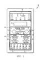
- FIG. 1is a front view of an analyzer 10 in the preferred embodiment of the present invention.
- the analyzerpreferably includes a plurality of control function activators 12 .
- Each of these activatorsmay activate an HVAC system's motor through low voltage interfaces.
- the activatorsmay be utilized to control a plurality of the motor's control line inputs.
- the activatorsmay include the following control inputs shown below in Table 1.
- Control FunctionActivator Control Line Input G FAN ONLY Y/Y2 Compressor (2 nd stage compressor in 2 stage systems) Y1 1 st stage compressor (in 2 stage systems O Changeover valve (heat pumps) W/W1 1 st stage heating Eht/W2 Emergency heat (heat pumps) or 2 nd stage heat Bk/PWM Activates to dehumidify airflow (BK/PWM). Also may activate PWM in continuously variable systems
- control function activatorsare merely exemplary. Any functions which are associated with control of a motor within an HVAC system may be used as a control function activator 12 .
- the table value selectors 20are four 4-position switches used to select one of four table elements from each of the four tables typically programed into an electronically-driven motor of an HVAC system. In most cases, these tables are accessed through a “tap” or “interface” board, that is part of or an accessory to the HVAC equipment, to select capacity, trim, delay, or airflow of the system. As illustrated, the terms Delay Table 22, Adjust Table 24, Cool Table 26, and Heat Table 28 are illustrated. However, the labels may vary, depending on the manufacturer's nomenclature. Preferably, each manufacturer's nomenclature may be utilized by overlaying a manufacturer specific label for each system undergoing service or being monitored.
- the display mode switch 30controls display parameters associated with a display 40 .
- the display mode switchcontrols display parameters associated with a display 40 .
- four selectionsmay be made.
- “Vth”displays the adjustable AC voltage used to measure and test the on/off threshold of the G and Y functions.
- “Vac”displays the system control transformer's supply voltage (normally, 18 Vac minimum to 30 Vac maximum, however the Vac display selection may show any voltage range).
- PWMturns on the control signal generator (specific to some HVAC systems) and displays the controlling duty cycle of that signal as a percentage ranging from 1.4% to 99.6%.
- the duty cycle displayedis selected from the source selected by a control mode selector 70 to be discussed below.
- Both internally and externally generated duty cyclesmay preferably be measured to within 0.2% duty cycle.
- “RPM”displays RPM of the motor (if available from the auxiliary output for the motor).
- the analyzer 10may use any type of display controls and parameters to determine the type of display shown on the display 40 .
- the analyzermay include two variable control knobs 32 such as a PWM Adjust control 34 and a Vth control 36 .
- the control knobsmay provide variable control of several system functions.
- the PWM Adjust control 34provides an internal, adjustable duty cycle signal for testing systems using the continuously variable mode of the motor.
- duty cycle adjustmentscan be made in 0.4% increments from 1.4% to 99.6%.
- these ranges and incrementsare exemplary and alternate embodiments of the present invention may utilize different functions, increments and ranges.
- the percentage PWM displayed in display 40is the percent duty cycle from the source selected by the control mode selector 70 .
- Vth control 36tests the “anticipator” thresholds of the G, Y/Y 2 , and Y 1 functions.
- the Vth controladjusts the amplitude of an internally generated variable amplitude sine wave voltage which can be supplied to the motor through the G and Y control function activators 12 .
- a switch 38adjacent the Vth control, is used to select either the variable voltage level from the Vth generator (Vth On) or the fixed voltage level from the low voltage transformer (Vth off). Specifically, the switch activates the Vth signal. Thus, when the “off” position is selected, the switch passes the fixed low voltage (normally 24-Vac) to the motor.
- the display 40may be any type of display which provides graphical representations from the parameters selected by the display mode switch 30 .
- the displayis a liquid crystal display.
- the lampsinclude a plurality of lights (preferably LEDs) representing the integrity of the motor connections. As illustrated, eight control functions of the motor (R, EM/W 2 , G, W/W 1 , O, BK, Y 1 , and Y/Y 2 ) and an auxiliary output (OUT) are shown. In the preferred embodiment of the present invention, the lights illuminate only when a connection to the input terminals of the motor and current is properly flowing through the interface. However, other visual signals may be established to display the status of various connections associated with the motor. For example, a light may illuminate when the connection is not operating correctly.
- FIG. 2is a right side view of the analyzer of FIG. 1 in the preferred embodiment of the present invention.
- the analyzerincludes the control mode selector 70 .
- the operatormay select either “System” or “Analyzer” to select a desired control mode.
- the analyzerIn the “Analyzer” mode, the analyzer generates and supplies command signals necessary to activate the HVAC system's motor.
- the “System” selectionmonitors the control signals generated by the HVAC's control system to the motor so that the system's operation can be assessed and faults diagnosed.
- the “System” modeprovides for an in-line mode. In this in-line mode, the analyzer 10 operates while the system is operating, monitoring the system's status and verifying the continuity of the control functions.
- a power pin-jack connection 76(labeled “B/C”) is also provided.
- the second mode“Analyzer” is used for the “Stand-Alone” control mode of operation, which independently exercises the motor with or without any connection with the system (with the exception of a low voltage power source) such as a 24-Vac power.
- a low voltage power sourcesuch as a 24-Vac power.
- the analyzer 10includes a motor cable port 72 which provides a receptacle port for a cable to be connected between the analyzer and the motor.
- FIG. 3is a left side view of the analyzer 10 of FIG. 1 in the preferred embodiment of the present invention.
- the analyzerincludes a control system cable port 74 which allows a cable to be connected from the analyzer to the control system.
- the motor cable port 72 and the control system cable port 74permit the analyzer to be inserted electrically between the HVAC controls and the Motor in the “In-Line” mode of operation.
- the in-line modeoperates while the motor is installed in the application and powered by the system.
- the connection to the HVAC systempermits the rapid and conclusive diagnosis of the wiring, hookup errors, motor faults, etc.
- the analyzermay also be operated in a “standalone” configuration in which only connections from the right side of the analyzer (FIG. 2) to the motor may be made (FIG. 8 ).
- a second power pin-jack connection 84(labeled “R”) is also located on the analyzer. The pin-jack connections enable the analyzer to be used in the “standalone” mode.
- the analyzermay include a verify commons switch 80 .
- the switchis used to troubleshoot the connection between the two commons required by the motor. Actuating the “Verify Commons” on the switch 80 forces a connection between the two commons between two electrical common connections (typically required in most common electronically-driven motors used in HVAC systems). The “verify commons” may be helpful in determining whether the commons are properly connected in the system.
- the analyzeralso includes a BK/PWM switch 82 for selecting either a variable duty cycle PWM signal or a low voltage 24-Vac signal. BK connects the selected signal to the motor. This signal or its equivalent are also a functional feature most common electronically-driven HVAC blower motors in use today.
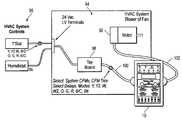
- FIG. 4is a simplified schematic block diagram of the analyzer 10 attached to an air conditioning system 90 in the preferred embodiment of the present invention.
- the air conditioning systemmay be any HVAC system.
- the analyzer 10specifically interfaces to the system 20 driven by a motor 92 .
- the motoris normally activated through low voltage (generally 24Vac nominal) connections.
- the motordrives a blower 94 .
- the motormay be any motor but, in the preferred embodiment of the present invention, is a brushless dc motor.
- the air conditioning systemalso includes an HVAC control system 96 and a tap board 98 .
- the analyzeris installed between a connection running from the tap board to the motor.
- the analyzeris attached within the air conditioning system by removing the connection between the motor and tap board.
- a tap board cable 100is attached from the tap board to the control system cable port 74 of the analyzer 10 .
- another motor cable 102is attached from the motor 92 to the motor cable port 72 of the analyzer.
- FIG. 5is a front perspective view of the analyzer 10 attached to the air conditioning system 90 .
- all panels of the air conditioning systemare completely closed when the analyzer is connected.
- accurate airflow performance, blower rpm, and motor currentare measured as would be seen in normal operation of the air conditioning system.
- FIG. 6is a front perspective view of the analyzer 10 attached to the motor 92 .
- the air conditioning system's 90 low voltage power supply(not shown), which powers the HVAC system controls 96 , energizes both the analyzer and the motor's control interface through the system connection cable.
- a separate 24VAC supplycan be connected through pin-jacks “R” and “B/C.”
- the analyzerprovides a positive indication that the control voltage is present on the motor cable 102 side of the motor's connector. For example, the “R” LED only illuminates if the motor completes the low voltage (e.g., 24-Vac) control circuit.
- a status lamp 50such as the “R” Led remains off, indicating the control transformer may not be activating the air conditioning system, the motor input is damaged, or not connected.
- the status lampsmay illuminate when a control circuit is open. Any visual status indicator may be utilized which provides an indication of an open or closed control circuit.
- the motor and controlsare not completing a circuit. This typically indicates a wiring error, a bad contact in the system connections, control board failure, or motor interface failure. If the technician is still unsure whether the status lamp was supposed to illuminate, or if the wrong status lamp illuminated upon activation of a control signal, the analyzer can be switched to the “Standalone” control mode by switching the control mode selector to “Analyzer.” With the control mode in “Analyzer,” the technician may then determine if the proper status lamp illuminates when the same control function is energized from the analyzer.
- the display 40may display the voltage level of the low voltage control system, RPM (if available in the motor program), percentage PWM, or Vth when the control mode selector is in either the system or analyzer control mode position.
- control signalsoriginate within the analyzer itself.
- the “Analyzer” positioncommands a disconnect for the system control functions to the motor and connects the analyzer 10 's control functions in the air conditioning system's place.
- the analyzeracts as a standalone control to activate the HVAC system as well as a monitor of the activation of the air conditioning system.
- the techniciancan activate the appropriate control functions from the analyzer and operate the motor through the control function activators 12 .
- each activatoris switched from the “off” position to the “on” position, an appropriate status lamp should illuminate for a completed control circuit.
- the technicianmay switch the control mode selector 70 between both “Analyzer” and “System” to isolate the sources of system faults to either the system side or the motor side of the air conditioning system.
- “System” and “Analyzer” control modeseach control signal can be initiated and verified. If a status lamp fails to illuminate when a control function is activated, the troubleshooting process indicates that the motor and controls are not completing a circuit which may be caused by a wiring error, bad contact in the system connections/control board, or motor interface failure.
- the technicianmay operate the analyzer in the “standalone” mode (“Analyzer” control mode) to ascertain if the proper status lamp illuminates when the same function is activated through the analyzer.
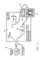
- FIG. 7is a simplified schematic block diagram of the analyzer 10 attached to the air conditioning system 90 in a “standalone” mode powered by a 24-volt AC power supply 110 .
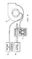
- FIG. 8is a simplified schematic block diagram of the analyzer of FIG. 7 connected to the motor 92 .
- the analyzercan be powered through the two power pin-jack connections 74 and 84 .
- the pin-jack connectionsmay be connected directly from the 24-volt power supply 110 .
- the separate power modemay be utilized to operate the air conditioning system 90 , a blower 94 , or a motor 92 alone.
- utilizing the analyzer from a separate power sourceprovides for a particularly effective training tool for demonstrations, blower or motor verification outside of an air conditioning system, or for laboratory/developmental tests.
- the control mode selector 70When the analyzer is powered from the power supply 110 , the control mode selector 70 must be in the “Analyzer” mode since the analyzer is not connected to any HVAC system controls 96 .
- the analyzerconfigured as illustrated and discussed in FIG. 7, the analyzer operates in the same manner as the “standalone” control mode, by providing commands directly to the motor through the analyzer.
- the analyzer 10may also be used during troubleshooting operations, as well as provide a self-contained capability to measure, test, and checkout circuit system parameters.
- the low voltage supplymay be measured on the display 40 . This can be accomplished by selecting the R(Vac) position on the display mode switch 30 .
- the analyzermay operate as a voltmeter, thus providng the technician with the versatility of the analyzer to perform multiple diagnostic functions.
- the analyzer 10may measure Y and G threshold voltage.
- the analyzermay test the control functions typically connected in conjunction with thermostat anticipators or control functions that can be actuated from electrical circuits that permit small currents to flow and voltages to be present even when the functions are intended to be off. These functions are typically the “Y” modes and the “Fan-only” (“G”) mode.
- the analyzermay generate a signal to test the activation level of those functions which are “thresholded” in the motor 92 . The level of voltage can then be viewed on the display 40 while the Vth control 36 is adjusted and the function is activated. It is then possible to determine the activation point of the G and Y functions.
- Y and G threshold voltageis a very unique and important feature of the analyzer.
- equipment manufacturers and service techniciansreported a large number of assumed motor faults because the Y or G lines would not turn the motor when the lines were applied, or the motor would not turn off when the lines were removed.
- Upon further investigation into most of these faultsit has been determined that a large number of these diagnosed “faults” were due to erroneous voltage on the Y and G terminals, and not motor faults. In most of these situations, the high or low voltage was due to high impedance contactors or relay coils, current leaked into Y and G from certain thermostat controls, faulty or misaligned anticipators, or solid state relays. These mis-diagnosed faults resulted in time consuming service calls or expensive and unnecessary motor replacement.
- a Vth threshold test performed by the technicianprovides a check of the voltage threshold of the preset Y and G functions in the motor. Once the motor's thresholds are verified, the technician can then proceed to determine other actual causes of the air conditioning system's malfunction.
- the control mode selector 70is set to the “Analyzer” position.
- the Vth switch 38is switched to the “on” position, resulting in the disconnection of the G, Y/Y 2 , and Y 1 functions from the power source 110 .
- the G, Y/Y 2 , and Y 1 functionsare then connected to an internal sine-wave generator located within or in combination with the analyzer (not shown).
- the Vth control 36is then actuated to adjust the voltage level.
- the display 40shows the voltage level (when the display mode switch 30 is set to Vth).
- the Y or G control functionsshould activate the motor when the Vth level is approximately fifty percent of the low voltage supply. If the adjustable level properly activates the function, the motor's internal interface is operating correctly and the motor is eliminated as the source of the system's problem. Next, the motor may then be connected back to the system controls 96 for further testing. If the motor does not activate, or activates significantly above or below fifty percent of the supply voltage level, the motor interface may be considered defective.
- the Vth switch 38is returned to the “off” position so that the G and Y signals return to the air conditioning system's power supply 110 .
- the analyzermay also measure RPM from the motor's auxiliary output (not shown) to give a check of the system's performance.
- the RPM readingmay be scaled to 12 pole brushless dc motors delivering 36 pulses per revolution (60 pulses per second per 100 RPM), in a similar fashion as most conventional air conditioning motors normally operate. In alternate embodiments of the present invention, scaling of motors having different numbers of poles and pulses per revolution may be utilized.
- the motortypically sends pulses whenever the motor is powered. These indicator pulses appear as approximately 150 RPM on the analyzer's display 40 . When G, Y and all other command functions are off, the presence of approximately 150 RPM on the display indicates that the motor is powered and properly sending the pulses.
- the analyzeralso includes an internal PWM generator for use in troubleshooting the air conditioning system 90 .
- the PWM generatoris particular effective for those air conditioning systems in which the percent duty cycle of a fixed period pulse rate is used to set airflow, mass flow, or to control motor torque (e.g., variable-speed systems).
- the BK/PWM switch 82To operate the internal PWM generator, the BK/PWM switch 82 must be set to the PWM setting, resulting in the generation of an internal PWM signal which can be supplied to the motor through the “BK” activator 12 . If the motor is programmed to accept a duty cycle input, the motor responds to the PWM signal by changing airflow and/or torque level to settle at a speed appropriate for the blower in which it is used.
- the analyzermay also utilize the internal PWM generator for systems whose normal operation uses fixed or discrete settings, rather than or in addition to continuously variable settings.
- the techniciancan them use airflow adjustments to determine duct or filter restriction to the air conditioning system, noise level at various airflow settings, power consumption comparisons, etc. After such evaluation and determination, the technician can then establish and return to fixed settings to reduce or accommodate the problems of the air conditioning system.
- the analyzer 10may also measure the duty cycle used to command blower airflow of the air conditioning system's 90 generator or the analyzer's own internal generator. When the control mode selector is set to the “System” position and a PWM sign is present, the system's PWM percentage duty cycled maybe measured and displayed. The analyzer may also measure the internally-generated PWM signal and display it on the display 40 by selecting the “Analyzer” position on the control mode selector 70 .
- the analyzerprovides a comparison of system operation with and without an assured connection between “C 1 ” and “C 2 ” in the motor connector.
- the C 1 and C 2 connectionsare two electrical common or “ground” connections which may be required in the proper operation of the motor's command functions.
- the analyzermay take several different forms.
- the general configurationmay be configured differently from that illustrated in FIGS. 1-8.
- the analyzermay be any device which provides a portable control apparatus having a plurality of independent diagnostic and control tools to troubleshoot an HVAC system.
- the analyzer 10provides many advantages over existing diagnostic devices.
- the analyzerprovides a plurality of diagnostic measurement devices allowing a technician to determine the parameters of the air conditioning system.
- the analyzerprovides a dual mode operation, a “standalone” control system and an “in-line” control system.
- the “standalone” control systemprovides solely for independent control of the air conditioning system, while the “in-line” control system enables a technician to both independently control the system and to monitor the system's control parameters of the air conditioning system's internal controls as it controls the system.
- the analyzeralso allows the technician to obtain various measures through the control of the motor, thereby providing another avenue to determine the source of the air conditioning system's problems.
Landscapes
- Physics & Mathematics (AREA)
- General Physics & Mathematics (AREA)
- Engineering & Computer Science (AREA)
- Automation & Control Theory (AREA)
- Air Conditioning Control Device (AREA)
Abstract
Description
1. Technical Field of the Invention
This invention relates to diagnostic devices, and more particularly, to a diagnostic apparatus that analyzes problems associated with air conditioning systems.
2. Description of Related Art
Heating, ventilation, and air conditioning (HVAC) systems are an important part of any modern residential or commercial building. As HVAC systems increase in complexity and capabilities, problems and servicing of these systems have also increased. It is quite common for a technician servicing or repairing an HVAC system to spend many hours in servicing and repairing the system. Currently, most controls associated with an HVAC system are located away from the main components of the HVAC system, such as the motor and blower units. When a technician is servicing an HVAC system, in order to troubleshoot or diagnose problems of the system, he must operate the HVAC in its various modes. However, since many control units are located away from the motor, the technician must travel between the two locations. In addition, to complicate matters, the technician normally does not have any portable instrumentation to determine if the connections between the control unit and the other HVAC system components are operating correctly. Furthermore, there are no available tools for comprehensive and process-oriented troubleshooting of the new electronically-driven motors prevalent in the HVAC market. A portable device is needed which enables a technician to control the HVAC system from a location adjacent the main HVAC system components and provides a plurality of diagnostic instrumentation to assist the technician in determining the problems associated with the HVAC system.
Although there are no known prior art teachings of a solution to the aforementioned deficiency and shortcoming such as that disclosed herein, prior art references that discuss subject matter that bears some relation to matters discussed herein are U.S. Pat. No. 5,682,329 to Seem et al. (Seem), U.S. Pat. No. 5,446,677 to Jensen et al. (Jensen), U.S. Pat. No. 5,892,690 to Boatman et al. (Boatman), and U.S. Pat. No. 5,555,509 to Dolan et al. (Dolan).
Seem discloses a diagnostic system for use in a network control system. The diagnostic system is used to analyze HVAC system or variable air volume (VAV) box performance in an environmental control system. The diagnostic system records temperature, air flow, and actuator position data in the controller associated with the VAV box and calculates an exponentially weighted moving average value. However, Seem does not teach or suggest providing an alternate control unit for control parameters within the environmental unit. Seem merely discloses monitoring the environmental unit without providing any control or troubleshooting capability.
Jensen also discloses a diagnostic system for use in a network control system. The diagnostic system is used to analyze VAV box performance in an environmental control system. The system allows a technician to perform diagnostic tests on VAV boxes from a remote location. The diagnostic system also formats the air flow so that it can be displayed as a graphical representation. However, Jensen does not teach or suggest controlling a plurality of control modes and functions separately from the internal environmental control unit. Jensen merely discloses limited control functions of actuators of a damper system of the VAV box.
Boatman discloses an environmental monitoring system and method for systematically and continuously monitoring an environment. The system and method includes a data acquisition system which is programmed to systematically collect environmental data for a site. The data acquisition system includes sensors coupled to a data storage device having a remote access device. Data may then be uploaded to the remote database for storing environment data from many sites. The remote database utilizes the remote access device so that the data storage devices of various data acquisition sites can be electronically coupled to the remote database for centralized data collection and storage. However, Boatman does not teach or suggest a system for remotely controlling a plurality of control modes and functions of the environmental unit. Rather, Boatman merely discloses monitoring a plurality of parameters within the environmental unit and storing the data in a remote location.
Dolan discloses a device for reading and transmitting control parameter selections to a control system for an HVAC system. The device reads and encodes all control parameter selections in a predefined manner in response to the control system. The device includes a programmed microprocessor that begins its regaining of control parameter selections from a beginning point in a software program. The microprocessor includes a switchable power supply which is periodically switched on and off by the control system that will be receiving and responding to the control parameter selections. However, Dolan does not teach or suggest providing control inputs to the HVAC system or a means for troubleshooting or diagnosing problems with the HVAC.
Review of the foregoing references reveals no disclosure or suggestion of an apparatus as that described and claimed herein. Thus, it would be a distinct advantage to have a portable device which provides remote control inputs to an HVAC system and the capability to troubleshoot and diagnose problems associated with the HVAC system. It is an object of the present invention to provide such an apparatus.
In one aspect, the present invention is a diagnostic apparatus for examining a heating, ventilation, and air conditioning (HVAC) system. The apparatus includes a control unit connected to the HVAC system for controlling a plurality of control parameters of the HVAC system. The apparatus also monitors a plurality of performance characteristics of the HVAC system. The control unit controls the plurality of control parameters and monitors the plurality of performance characteristics to provide a diagnostic check of the HVAC system.
In another aspect, the present invention is an apparatus for examining a heating, ventilation, and air conditioning (HVAC) system. The apparatus includes a portable control unit detachably coupled to the HVAC system. The control unit monitors a plurality of performance characteristics associated with a plurality of control parameters controlling the HVAC system. The control unit also controls the HVAC system through the plurality of control parameters of the HVAC system. The control unit monitors the plurality of performance characteristics while controlling the HVAC system to determine a status of the HVAC system.
In still another aspect, the present invention is a diagnostic apparatus for examining a heating, ventilation, and air conditioning (HVAC) system. The apparatus includes a control unit connected to the HVAC system. The control unit controls a plurality of control parameters of the HVAC system through a plurality of control function activators providing control functions to the HVAC system. The control unit also variably controls at least one control parameter and monitors a plurality of performance characteristics of the HVAC system. The control unit controls the plurality of control parameters and monitors the plurality of performance characteristics to perform a diagnostic check of the HVAC system.
The invention will be better understood and its numerous objects and advantages will become more apparent to those skilled in the art by reference to the following drawings, in conjunction with the accompanying specification, in which:
FIG. 1 is a front view of an analyzer in the preferred embodiment of the present invention;
FIG. 2 is a right side view of the analyzer of FIG. 1 in the preferred embodiment of the present invention;
FIG. 3 is a left side view of the analyzer of FIG. 1 in the preferred embodiment of the present invention;
FIG. 4 is a simplified schematic block diagram of the analyzer attached to an air conditioning system in the preferred embodiment of the present invention;
FIG. 5 is a front perspective view of the analyzer attached to the air conditioning system;
FIG. 6 is a front perspective view of the analyzer attached to the motor;
FIG. 7 is a simplified schematic block diagram of the analyzer attached to the air conditioning system in a standalone mode powered by a 24-volt AC power supply; and
FIG. 8 is a simplified schematic block diagram of the analyzer of FIG. 7 connected to the motor.
A diagnostic device for analyzing and troubleshooting an HVAC system is disclosed. FIG. 1 is a front view of ananalyzer 10 in the preferred embodiment of the present invention. The analyzer preferably includes a plurality ofcontrol function activators 12. Each of these activators may activate an HVAC system's motor through low voltage interfaces. The activators may be utilized to control a plurality of the motor's control line inputs. For example, the activators may include the following control inputs shown below in Table 1.
| TABLE 1 |
| Control Function Activators |
| Control Function Activator | Control Line Input |
| G | FAN ONLY |
| Y/Y2 | Compressor (2ndstage compressor in 2 stage |
| systems) | |
| 1ststage compressor (in 2 stage systems | |
| O | Changeover valve (heat pumps) |
| W/ | 1ststage heating |
| Eht/W2 | Emergency heat (heat pumps) or 2ndstage |
| heat | |
| Bk/PWM | Activates to dehumidify airflow (BK/PWM). |
| Also may activate PWM in continuously | |
| variable systems | |
It should be understood that the above control function activators are merely exemplary. Any functions which are associated with control of a motor within an HVAC system may be used as acontrol function activator 12.
Still referring to FIG. 1, located above the plurality ofcontrol function activators 12 are thetable value selectors 20. The table value selectors are four 4-position switches used to select one of four table elements from each of the four tables typically programed into an electronically-driven motor of an HVAC system. In most cases, these tables are accessed through a “tap” or “interface” board, that is part of or an accessory to the HVAC equipment, to select capacity, trim, delay, or airflow of the system. As illustrated, the terms Delay Table 22, Adjust Table 24, Cool Table 26, and Heat Table 28 are illustrated. However, the labels may vary, depending on the manufacturer's nomenclature. Preferably, each manufacturer's nomenclature may be utilized by overlaying a manufacturer specific label for each system undergoing service or being monitored.
Above thetable value selectors 20 is thedisplay mode switch 30. The display mode switch controls display parameters associated with adisplay 40. In the preferred embodiment of the present invention, four selections may be made. In the first selection, “Vth” displays the adjustable AC voltage used to measure and test the on/off threshold of the G and Y functions. In the second selection, “Vac” displays the system control transformer's supply voltage (normally, 18 Vac minimum to 30 Vac maximum, however the Vac display selection may show any voltage range). In the third selection, “PWM” turns on the control signal generator (specific to some HVAC systems) and displays the controlling duty cycle of that signal as a percentage ranging from 1.4% to 99.6%. The duty cycle displayed is selected from the source selected by acontrol mode selector 70 to be discussed below. Both internally and externally generated duty cycles may preferably be measured to within 0.2% duty cycle. In the fourth selection, “RPM” displays RPM of the motor (if available from the auxiliary output for the motor). In alternate embodiments of the present invention, theanalyzer 10 may use any type of display controls and parameters to determine the type of display shown on thedisplay 40. The analyzer may include two variable control knobs32 such as a PWM Adjustcontrol 34 and aVth control 36. The control knobs may provide variable control of several system functions. The PWM Adjustcontrol 34 provides an internal, adjustable duty cycle signal for testing systems using the continuously variable mode of the motor. Preferably, duty cycle adjustments can be made in 0.4% increments from 1.4% to 99.6%. However, these ranges and increments are exemplary and alternate embodiments of the present invention may utilize different functions, increments and ranges. The percentage PWM displayed indisplay 40 is the percent duty cycle from the source selected by thecontrol mode selector 70.
Thedisplay 40 may be any type of display which provides graphical representations from the parameters selected by thedisplay mode switch 30. However, in the preferred embodiment of the present invention, the display is a liquid crystal display.
Located above thedisplay 40 are the controlfunction status lamps 50. The lamps include a plurality of lights (preferably LEDs) representing the integrity of the motor connections. As illustrated, eight control functions of the motor (R, EM/W2, G, W/W1, O, BK, Y1, and Y/Y2) and an auxiliary output (OUT) are shown. In the preferred embodiment of the present invention, the lights illuminate only when a connection to the input terminals of the motor and current is properly flowing through the interface. However, other visual signals may be established to display the status of various connections associated with the motor. For example, a light may illuminate when the connection is not operating correctly.
FIG. 2 is a right side view of the analyzer of FIG. 1 in the preferred embodiment of the present invention. The analyzer includes thecontrol mode selector 70. The operator may select either “System” or “Analyzer” to select a desired control mode. In the “Analyzer” mode, the analyzer generates and supplies command signals necessary to activate the HVAC system's motor. On the other hand, the “System” selection monitors the control signals generated by the HVAC's control system to the motor so that the system's operation can be assessed and faults diagnosed. The “System” mode provides for an in-line mode. In this in-line mode, theanalyzer 10 operates while the system is operating, monitoring the system's status and verifying the continuity of the control functions. In addition, a power pin-jack connection76 (labeled “B/C”) is also provided.
The second mode, “Analyzer” is used for the “Stand-Alone” control mode of operation, which independently exercises the motor with or without any connection with the system (with the exception of a low voltage power source) such as a 24-Vac power. By providing a dual mode operation of the motor (i.e., operating the motor either from the system or through an independent signal source generated in the analyzer while the system is intact), provides a technician powerful diagnostic troubleshooting capabilities.
Still referring to FIG. 2, theanalyzer 10 includes a motor cable port72 which provides a receptacle port for a cable to be connected between the analyzer and the motor.
FIG. 3 is a left side view of theanalyzer 10 of FIG. 1 in the preferred embodiment of the present invention. The analyzer includes a control system cable port74 which allows a cable to be connected from the analyzer to the control system. The motor cable port72 and the control system cable port74 permit the analyzer to be inserted electrically between the HVAC controls and the Motor in the “In-Line” mode of operation. The in-line mode operates while the motor is installed in the application and powered by the system. The connection to the HVAC system permits the rapid and conclusive diagnosis of the wiring, hookup errors, motor faults, etc.
The analyzer may also be operated in a “standalone” configuration in which only connections from the right side of the analyzer (FIG. 2) to the motor may be made (FIG.8). In addition, a second power pin-jack connection84 (labeled “R”) is also located on the analyzer. The pin-jack connections enable the analyzer to be used in the “standalone” mode.
In addition, the analyzer may include a verify commons switch80. The switch is used to troubleshoot the connection between the two commons required by the motor. Actuating the “Verify Commons” on theswitch 80 forces a connection between the two commons between two electrical common connections (typically required in most common electronically-driven motors used in HVAC systems). The “verify commons” may be helpful in determining whether the commons are properly connected in the system. The analyzer also includes a BK/PWM switch 82 for selecting either a variable duty cycle PWM signal or a low voltage 24-Vac signal. BK connects the selected signal to the motor. This signal or its equivalent are also a functional feature most common electronically-driven HVAC blower motors in use today.
FIG. 4 is a simplified schematic block diagram of theanalyzer 10 attached to anair conditioning system 90 in the preferred embodiment of the present invention. The air conditioning system may be any HVAC system. Theanalyzer 10 specifically interfaces to thesystem 20 driven by amotor 92. The motor is normally activated through low voltage (generally 24Vac nominal) connections. The motor drives ablower 94. The motor may be any motor but, in the preferred embodiment of the present invention, is a brushless dc motor. The air conditioning system also includes anHVAC control system 96 and atap board 98. The analyzer is installed between a connection running from the tap board to the motor.
The analyzer is attached within the air conditioning system by removing the connection between the motor and tap board. Atap board cable 100 is attached from the tap board to the control system cable port74 of theanalyzer 10. In addition, anothermotor cable 102 is attached from themotor 92 to the motor cable port72 of the analyzer.
FIG. 5 is a front perspective view of theanalyzer 10 attached to theair conditioning system 90. Preferably, all panels of the air conditioning system are completely closed when the analyzer is connected. Thus, accurate airflow performance, blower rpm, and motor current are measured as would be seen in normal operation of the air conditioning system. FIG. 6 is a front perspective view of theanalyzer 10 attached to themotor 92.
As illustrated in FIG. 4, the air conditioning system's 90 low voltage power supply (not shown), which powers the HVAC system controls96, energizes both the analyzer and the motor's control interface through the system connection cable. Alternatively, if the low voltage power is not available through the system connection, a separate 24VAC supply can be connected through pin-jacks “R” and “B/C.” The analyzer provides a positive indication that the control voltage is present on themotor cable 102 side of the motor's connector. For example, the “R” LED only illuminates if the motor completes the low voltage (e.g., 24-Vac) control circuit. If the low voltage control circuit is open, astatus lamp 50 such as the “R” Led remains off, indicating the control transformer may not be activating the air conditioning system, the motor input is damaged, or not connected. In alternate embodiments of the present invention, the status lamps may illuminate when a control circuit is open. Any visual status indicator may be utilized which provides an indication of an open or closed control circuit.
In the preferred embodiment of the present invention, when one of thestatus lamps 50 fails to illuminate during activation of a control signal, the motor and controls are not completing a circuit. This typically indicates a wiring error, a bad contact in the system connections, control board failure, or motor interface failure. If the technician is still unsure whether the status lamp was supposed to illuminate, or if the wrong status lamp illuminated upon activation of a control signal, the analyzer can be switched to the “Standalone” control mode by switching the control mode selector to “Analyzer.” With the control mode in “Analyzer,” the technician may then determine if the proper status lamp illuminates when the same control function is energized from the analyzer. By utilizing the two modes, “Analyzer” and “System,” a technician can diagnose wiring faults to the source on either side of the analyzer (i.e., to themotor 92 or to the HVAC system controls96). In addition, thedisplay 40 may display the voltage level of the low voltage control system, RPM (if available in the motor program), percentage PWM, or Vth when the control mode selector is in either the system or analyzer control mode position.
Referring to FIGS. 1-5, with the control mode selector is in the “Analyzer” position, control signals originate within the analyzer itself. The “Analyzer” position commands a disconnect for the system control functions to the motor and connects theanalyzer 10's control functions in the air conditioning system's place. In the “Analyzer” mode, the analyzer acts as a standalone control to activate the HVAC system as well as a monitor of the activation of the air conditioning system. The technician can activate the appropriate control functions from the analyzer and operate the motor through thecontrol function activators 12. When each activator is switched from the “off” position to the “on” position, an appropriate status lamp should illuminate for a completed control circuit.
In operation, the technician may switch thecontrol mode selector 70 between both “Analyzer” and “System” to isolate the sources of system faults to either the system side or the motor side of the air conditioning system. By alternately switching between “System” and “Analyzer” control modes, each control signal can be initiated and verified. If a status lamp fails to illuminate when a control function is activated, the troubleshooting process indicates that the motor and controls are not completing a circuit which may be caused by a wiring error, bad contact in the system connections/control board, or motor interface failure. When the technician is still not sure why a status lamp is not properly illuminated or an incorrect status lamp illuminates, the technician may operate the analyzer in the “standalone” mode (“Analyzer” control mode) to ascertain if the proper status lamp illuminates when the same function is activated through the analyzer.
FIG. 7 is a simplified schematic block diagram of theanalyzer 10 attached to theair conditioning system 90 in a “standalone” mode powered by a 24-voltAC power supply 110. FIG. 8 is a simplified schematic block diagram of the analyzer of FIG. 7 connected to themotor 92. In the situation when a connection through the HVAC system is not needed or accessible, the analyzer can be powered through the two power pin-jack connections 74 and84. The pin-jack connections may be connected directly from the 24-volt power supply 110. The separate power mode may be utilized to operate theair conditioning system 90, ablower 94, or amotor 92 alone. Additionally, utilizing the analyzer from a separate power source (separate from a high voltage power source120) provides for a particularly effective training tool for demonstrations, blower or motor verification outside of an air conditioning system, or for laboratory/developmental tests. When the analyzer is powered from thepower supply 110, thecontrol mode selector 70 must be in the “Analyzer” mode since the analyzer is not connected to any HVAC system controls96. With the analyzer configured as illustrated and discussed in FIG. 7, the analyzer operates in the same manner as the “standalone” control mode, by providing commands directly to the motor through the analyzer.
Theanalyzer 10 may also be used during troubleshooting operations, as well as provide a self-contained capability to measure, test, and checkout circuit system parameters. For example, the low voltage supply may be measured on thedisplay 40. This can be accomplished by selecting the R(Vac) position on thedisplay mode switch 30. The analyzer may operate as a voltmeter, thus providng the technician with the versatility of the analyzer to perform multiple diagnostic functions.
In addition, theanalyzer 10 may measure Y and G threshold voltage. The analyzer may test the control functions typically connected in conjunction with thermostat anticipators or control functions that can be actuated from electrical circuits that permit small currents to flow and voltages to be present even when the functions are intended to be off. These functions are typically the “Y” modes and the “Fan-only” (“G”) mode. The analyzer may generate a signal to test the activation level of those functions which are “thresholded” in themotor 92. The level of voltage can then be viewed on thedisplay 40 while theVth control 36 is adjusted and the function is activated. It is then possible to determine the activation point of the G and Y functions.
The determination of Y and G threshold voltage is a very unique and important feature of the analyzer. Over the years, equipment manufacturers and service technicians reported a large number of assumed motor faults because the Y or G lines would not turn the motor when the lines were applied, or the motor would not turn off when the lines were removed. Upon further investigation into most of these faults, it has been determined that a large number of these diagnosed “faults” were due to erroneous voltage on the Y and G terminals, and not motor faults. In most of these situations, the high or low voltage was due to high impedance contactors or relay coils, current leaked into Y and G from certain thermostat controls, faulty or misaligned anticipators, or solid state relays. These mis-diagnosed faults resulted in time consuming service calls or expensive and unnecessary motor replacement.
A Vth threshold test performed by the technician provides a check of the voltage threshold of the preset Y and G functions in the motor. Once the motor's thresholds are verified, the technician can then proceed to determine other actual causes of the air conditioning system's malfunction. To begin the threshold test, thecontrol mode selector 70 is set to the “Analyzer” position. TheVth switch 38 is switched to the “on” position, resulting in the disconnection of the G, Y/Y2, and Y1 functions from thepower source 110. The G, Y/Y2, and Y1 functions are then connected to an internal sine-wave generator located within or in combination with the analyzer (not shown). TheVth control 36 is then actuated to adjust the voltage level. Thedisplay 40 shows the voltage level (when thedisplay mode switch 30 is set to Vth). The Y or G control functions, during testing, should activate the motor when the Vth level is approximately fifty percent of the low voltage supply. If the adjustable level properly activates the function, the motor's internal interface is operating correctly and the motor is eliminated as the source of the system's problem. Next, the motor may then be connected back to the system controls96 for further testing. If the motor does not activate, or activates significantly above or below fifty percent of the supply voltage level, the motor interface may be considered defective. Once the test is completed, theVth switch 38 is returned to the “off” position so that the G and Y signals return to the air conditioning system'spower supply 110.
In many situations, a technician may find it necessary to correlate airflow or sound level toblower 94 speed. The analyzer may also measure RPM from the motor's auxiliary output (not shown) to give a check of the system's performance. The RPM reading may be scaled to 12 pole brushless dc motors delivering 36 pulses per revolution (60 pulses per second per 100 RPM), in a similar fashion as most conventional air conditioning motors normally operate. In alternate embodiments of the present invention, scaling of motors having different numbers of poles and pulses per revolution may be utilized.
The motor typically sends pulses whenever the motor is powered. These indicator pulses appear as approximately 150 RPM on the analyzer'sdisplay 40. When G, Y and all other command functions are off, the presence of approximately 150 RPM on the display indicates that the motor is powered and properly sending the pulses.
The analyzer also includes an internal PWM generator for use in troubleshooting theair conditioning system 90. The PWM generator is particular effective for those air conditioning systems in which the percent duty cycle of a fixed period pulse rate is used to set airflow, mass flow, or to control motor torque (e.g., variable-speed systems). To operate the internal PWM generator, the BK/PWM switch 82 must be set to the PWM setting, resulting in the generation of an internal PWM signal which can be supplied to the motor through the “BK”activator 12. If the motor is programmed to accept a duty cycle input, the motor responds to the PWM signal by changing airflow and/or torque level to settle at a speed appropriate for the blower in which it is used. The analyzer may also utilize the internal PWM generator for systems whose normal operation uses fixed or discrete settings, rather than or in addition to continuously variable settings. The technician can them use airflow adjustments to determine duct or filter restriction to the air conditioning system, noise level at various airflow settings, power consumption comparisons, etc. After such evaluation and determination, the technician can then establish and return to fixed settings to reduce or accommodate the problems of the air conditioning system.
Theanalyzer 10 may also measure the duty cycle used to command blower airflow of the air conditioning system's90 generator or the analyzer's own internal generator. When the control mode selector is set to the “System” position and a PWM sign is present, the system's PWM percentage duty cycled maybe measured and displayed. The analyzer may also measure the internally-generated PWM signal and display it on thedisplay 40 by selecting the “Analyzer” position on thecontrol mode selector 70.
In addition, by activating the verify commons switch80, the analyzer provides a comparison of system operation with and without an assured connection between “C1” and “C2” in the motor connector. The C1 and C2 connections are two electrical common or “ground” connections which may be required in the proper operation of the motor's command functions.
In alternate embodiments of the present invention, the analyzer may take several different forms. For example, the general configuration may be configured differently from that illustrated in FIGS. 1-8. However, it should be understood that the analyzer may be any device which provides a portable control apparatus having a plurality of independent diagnostic and control tools to troubleshoot an HVAC system.
Theanalyzer 10 provides many advantages over existing diagnostic devices. The analyzer provides a plurality of diagnostic measurement devices allowing a technician to determine the parameters of the air conditioning system. In addition, the analyzer provides a dual mode operation, a “standalone” control system and an “in-line” control system. The “standalone” control system provides solely for independent control of the air conditioning system, while the “in-line” control system enables a technician to both independently control the system and to monitor the system's control parameters of the air conditioning system's internal controls as it controls the system. The analyzer also allows the technician to obtain various measures through the control of the motor, thereby providing another avenue to determine the source of the air conditioning system's problems.
It is thus believed that the operation and construction of the present invention will be apparent from the foregoing description. While the apparatus shown and described has been characterized as being preferred, it will be readily apparent that various changes and modifications could be made therein without departing from the scope of the invention as defined in the following claims.
Claims (19)
1. A diagnostic apparatus for examining a heating, ventilation, and air conditioning (HVAC) system having an internal controller sending control signals to an electronically-driven motor of the HVAC system, said apparatus comprising:
a control unit detachably connected to the HVAC system, said control unit controlling a plurality of control parameters associated with the electronically-driven motor of the HVAC system; and
means for said control unit to monitor a plurality of performance characteristics associated with the electronically-driven motor of the HVAC system;
means for said control unit to monitor the control signals of the HVAC System's internal controller;
whereby said control unit monitors the plurality of performance characteristics while controlling the HVAC system to provide a diagnostic check of the HVAC system.
2. The diagnostic apparatus ofclaim 1 wherein said control unit controls a plurality of control parameters through a plurality of control function activators providing control functions to the electronically-driven motor of the HVAC system.
3. The diagnostic apparatus ofclaim 2 wherein said control function activators provide control functions directly to the HVAC system.
4. The diagnostic apparatus ofclaim 1 wherein said control unit controls a plurality of control parameters as a control system separate from internal controls of the HVAC system, wherein said control unit controls the plurality of control parameters upon activation of a single switch, thereby isolating the HVAC System's internal controls from the electronically-driven motor.
5. The diagnostic apparatus ofclaim 1 wherein said control unit includes a visual indication of at least one properly functioning control circuit associated with at least one of the plurality of control parameters of the HVAC system.
6. The diagnostic apparatus ofclaim 1 wherein said control unit includes means for variably adjusting and thereby controlling at least one control parameter of the HVAC system over a continuous range of operation.
7. The diagnostic apparatus ofclaim 6 wherein said variable control means is a pulse width adjuster to test and verify operation of control parameters that respond to a duty cycle.
8. The diagnostic apparatus ofclaim 6 wherein said variable control means is a variable voltage threshold (Vth) function adjuster.
9. The diagnostic apparatus ofclaim 1 wherein said means for said control unit to monitor a plurality of performance characteristics of the HVAC system includes a display providing a graphical representation of at least one performance characteristic.
10. The diagnostic apparatus ofclaim 1 wherein said control unit is powered from a power source separate from any power source powering the HVAC system.
11. The diagnostic apparatus ofclaim 1 wherein said control unit is powered by the same power source powering the HVAC system.
12. The diagnostic apparatus ofclaim 1 wherein said control unit connected to the HVAC system with a first cable extending from said control unit to a control system of the HVAC system and a second cable connecting said control unit to a the electronically-driven motor driving the HVAC system.
13. The diagnostic apparatus ofclaim 1 wherein said monitoring means of a plurality of performance characteristics includes monitoring a voltage associated with the HVAC system.
14. The diagnostic apparatus ofclaim 1 wherein said monitoring means of a plurality of performance characteristics includes monitoring a revolution per minute count of the electronically-driven-motor operating the HVAC system, wherein the performance characteristics include the current operating speed of the electronically-driven motor.
15. The diagnostic apparatus ofclaim 1 wherein said monitoring means of a plurality of performance characteristics includes monitoring a Y and G threshold voltages, the Y and G threshold voltages providing activation threshold voltages for operating a motor associated with the HVAC system.
16. The diagnostic apparatus ofclaim 1 wherein said control unit includes a PWM duty cycle generator to test and verify operation of motors or other control actuators that respond to a duty cycle.
17. The diagnostic apparatus ofclaim 1 wherein:
the HVAC system includes a control system controlling a motor within the HVAC system; and
said control unit includes a selectable switch, said switch allowing said control unit to operate in a first mode to monitor a plurality of interconnected functions between the HVAC system and the motor and a second mode to disconnect the control system from operating and controlling the motor;
whereby switching between the first mode and the second mode provides means for isolating a location of a malfunction occurring within the HVAC system.
18. An apparatus for examining a heating, ventilation, and air conditioning (HVAC) system having an internal controller sending control signals to an electronically-driven motor of the HVAC system, said apparatus comprising:
a portable control unit detachably coupled to the HVAC system, said control unit monitoring a plurality of performance characteristics associated with a plurality of control parameters controlling the electronically-driven motor of the HVAC system and monitoring the control signals of the internal controller; and
means for controlling the electronically-driven motor of the HVAC system within the portable control unit through the plurality of control parameters of the HVAC system;
whereby said control unit monitors the plurality of performance characteristics while controlling the electronically-driven motor of the HVAC system to determine a status of the HVAC system.
19. A diagnostic apparatus for examination of a heating, ventilation, and air conditioning (HVAC) system having an internal controller sending control signals to an electronically-driven motor of the HVAC system, said apparatus comprising:
a control unit having connecting means to the HVAC system, said control unit controlling a plurality of control parameters of the electronically-driven motor of the HVAC system through a plurality of control function activators providing control functions to the HVAC system, said control unit variably controlling at least one control parameter; and
means for said control unit to monitor a plurality of performance characteristics of the electronically-driven motor of the HVAC system;
means for said control unit to monitor the control signals of the internal controller;
whereby said control unit monitors the plurality of performance characteristics while controlling the HVAC system to provide a diagnostic check of the HVAC system.
Priority Applications (1)
| Application Number | Priority Date | Filing Date | Title |
|---|---|---|---|
| US09/955,659US6826454B2 (en) | 2001-09-19 | 2001-09-19 | Air conditioning diagnostic analyzer |
Applications Claiming Priority (1)
| Application Number | Priority Date | Filing Date | Title |
|---|---|---|---|
| US09/955,659US6826454B2 (en) | 2001-09-19 | 2001-09-19 | Air conditioning diagnostic analyzer |
Publications (2)
| Publication Number | Publication Date |
|---|---|
| US20030060933A1 US20030060933A1 (en) | 2003-03-27 |
| US6826454B2true US6826454B2 (en) | 2004-11-30 |
Family
ID=25497155
Family Applications (1)
| Application Number | Title | Priority Date | Filing Date |
|---|---|---|---|
| US09/955,659Expired - Fee RelatedUS6826454B2 (en) | 2001-09-19 | 2001-09-19 | Air conditioning diagnostic analyzer |
Country Status (1)
| Country | Link |
|---|---|
| US (1) | US6826454B2 (en) |
Cited By (154)
| Publication number | Priority date | Publication date | Assignee | Title |
|---|---|---|---|---|
| US20040130454A1 (en)* | 2003-01-07 | 2004-07-08 | Barton Errol Wendell | Thermostatic controller and circuit tester |
| US20050159924A1 (en)* | 2004-01-20 | 2005-07-21 | Shah Rajendra K. | Ordered record of system-wide fault in an HVAC system |
| US20050159847A1 (en)* | 2004-01-20 | 2005-07-21 | Shah Rajendra K. | Service and diagnostic tool for HVAC systems |
| US7031880B1 (en)* | 2004-05-07 | 2006-04-18 | Johnson Controls Technology Company | Method and apparatus for assessing performance of an environmental control system |
| US20060179341A1 (en)* | 2005-02-04 | 2006-08-10 | York International Corporation | Method of clearing an HVAC control fault code memory |
| US20070143451A1 (en)* | 2005-12-20 | 2007-06-21 | Johnson Controls Technology Company | System and method for configuring a control system |
| US20070170171A1 (en)* | 2006-01-20 | 2007-07-26 | Shah Rajendra K | Method and apparatus for measurement of AC voltages in an HVAC system |
| US20090009115A1 (en)* | 2004-06-04 | 2009-01-08 | Belimo Holding Ag | Brushless Dc-Motor |
| US20090018719A1 (en)* | 2007-07-13 | 2009-01-15 | Cummins, Inc. | Interface and monitoring system and method for a vehicle idling control |
| US20090128068A1 (en)* | 2006-08-01 | 2009-05-21 | Paul Steven Mullin | Interface cord and system including an interface cord |
| US20110077780A1 (en)* | 2006-11-30 | 2011-03-31 | Honeywell International Inc. | Hvac controller with checkout utility |
| USD648642S1 (en) | 2009-10-21 | 2011-11-15 | Lennox Industries Inc. | Thin cover plate for an electronic system controller |
| USD648641S1 (en) | 2009-10-21 | 2011-11-15 | Lennox Industries Inc. | Thin cover plate for an electronic system controller |
| US8232860B2 (en) | 2005-10-21 | 2012-07-31 | Honeywell International Inc. | RFID reader for facility access control and authorization |
| US20120192955A1 (en)* | 2011-01-28 | 2012-08-02 | Yamatake Corporation | Air conditioning controlling device and method |
| US8239066B2 (en) | 2008-10-27 | 2012-08-07 | Lennox Industries Inc. | System and method of use for a user interface dashboard of a heating, ventilation and air conditioning network |
| US8255086B2 (en) | 2008-10-27 | 2012-08-28 | Lennox Industries Inc. | System recovery in a heating, ventilation and air conditioning network |
| US8260444B2 (en) | 2010-02-17 | 2012-09-04 | Lennox Industries Inc. | Auxiliary controller of a HVAC system |
| US8295981B2 (en) | 2008-10-27 | 2012-10-23 | Lennox Industries Inc. | Device commissioning in a heating, ventilation and air conditioning network |
| CN101751019B (en)* | 2008-12-18 | 2012-12-12 | 珠海格力电器股份有限公司 | Monitoring system for environmental simulation |
| US8351350B2 (en) | 2007-05-28 | 2013-01-08 | Honeywell International Inc. | Systems and methods for configuring access control devices |
| US8352081B2 (en) | 2008-10-27 | 2013-01-08 | Lennox Industries Inc. | Communication protocol system and method for a distributed-architecture heating, ventilation and air conditioning network |
| US8352080B2 (en) | 2008-10-27 | 2013-01-08 | Lennox Industries Inc. | Communication protocol system and method for a distributed-architecture heating, ventilation and air conditioning network |
| US8433446B2 (en) | 2008-10-27 | 2013-04-30 | Lennox Industries, Inc. | Alarm and diagnostics system and method for a distributed-architecture heating, ventilation and air conditioning network |
| US8437878B2 (en) | 2008-10-27 | 2013-05-07 | Lennox Industries Inc. | Alarm and diagnostics system and method for a distributed architecture heating, ventilation and air conditioning network |
| US8437877B2 (en) | 2008-10-27 | 2013-05-07 | Lennox Industries Inc. | System recovery in a heating, ventilation and air conditioning network |
| US8442693B2 (en) | 2008-10-27 | 2013-05-14 | Lennox Industries, Inc. | System and method of use for a user interface dashboard of a heating, ventilation and air conditioning network |
| US8452456B2 (en) | 2008-10-27 | 2013-05-28 | Lennox Industries Inc. | System and method of use for a user interface dashboard of a heating, ventilation and air conditioning network |
| US8452906B2 (en) | 2008-10-27 | 2013-05-28 | Lennox Industries, Inc. | Communication protocol system and method for a distributed-architecture heating, ventilation and air conditioning network |
| US8463443B2 (en) | 2008-10-27 | 2013-06-11 | Lennox Industries, Inc. | Memory recovery scheme and data structure in a heating, ventilation and air conditioning network |
| US8463442B2 (en) | 2008-10-27 | 2013-06-11 | Lennox Industries, Inc. | Alarm and diagnostics system and method for a distributed architecture heating, ventilation and air conditioning network |
| US20130204440A1 (en)* | 2010-11-19 | 2013-08-08 | Nest Labs, Inc. | Hvac controller with user-friendly installation features with wire insertion detection |
| US8543243B2 (en) | 2008-10-27 | 2013-09-24 | Lennox Industries, Inc. | System and method of use for a user interface dashboard of a heating, ventilation and air conditioning network |
| US8548630B2 (en) | 2008-10-27 | 2013-10-01 | Lennox Industries, Inc. | Alarm and diagnostics system and method for a distributed-architecture heating, ventilation and air conditioning network |
| US8544285B2 (en)* | 2010-11-19 | 2013-10-01 | Nest Labs, Inc. | HVAC controller with user-friendly installation features facilitating both do-it-yourself and professional installation scenarios |
| US8560125B2 (en) | 2008-10-27 | 2013-10-15 | Lennox Industries | Communication protocol system and method for a distributed-architecture heating, ventilation and air conditioning network |
| US8564400B2 (en) | 2008-10-27 | 2013-10-22 | Lennox Industries, Inc. | Communication protocol system and method for a distributed-architecture heating, ventilation and air conditioning network |
| US8600559B2 (en) | 2008-10-27 | 2013-12-03 | Lennox Industries Inc. | Method of controlling equipment in a heating, ventilation and air conditioning network |
| US8598982B2 (en) | 2007-05-28 | 2013-12-03 | Honeywell International Inc. | Systems and methods for commissioning access control devices |
| US8600558B2 (en) | 2008-10-27 | 2013-12-03 | Lennox Industries Inc. | System recovery in a heating, ventilation and air conditioning network |
| US8615326B2 (en) | 2008-10-27 | 2013-12-24 | Lennox Industries Inc. | System and method of use for a user interface dashboard of a heating, ventilation and air conditioning network |
| US8655490B2 (en) | 2008-10-27 | 2014-02-18 | Lennox Industries, Inc. | System and method of use for a user interface dashboard of a heating, ventilation and air conditioning network |
| US8655491B2 (en) | 2008-10-27 | 2014-02-18 | Lennox Industries Inc. | Alarm and diagnostics system and method for a distributed architecture heating, ventilation and air conditioning network |
| US8661165B2 (en) | 2008-10-27 | 2014-02-25 | Lennox Industries, Inc. | Device abstraction system and method for a distributed architecture heating, ventilation and air conditioning system |
| US8694164B2 (en) | 2008-10-27 | 2014-04-08 | Lennox Industries, Inc. | Interactive user guidance interface for a heating, ventilation and air conditioning system |
| US8707414B2 (en) | 2010-01-07 | 2014-04-22 | Honeywell International Inc. | Systems and methods for location aware access control management |
| US8725298B2 (en) | 2008-10-27 | 2014-05-13 | Lennox Industries, Inc. | Alarm and diagnostics system and method for a distributed architecture heating, ventilation and conditioning network |
| US8744629B2 (en) | 2008-10-27 | 2014-06-03 | Lennox Industries Inc. | System and method of use for a user interface dashboard of a heating, ventilation and air conditioning network |
| US8762666B2 (en) | 2008-10-27 | 2014-06-24 | Lennox Industries, Inc. | Backup and restoration of operation control data in a heating, ventilation and air conditioning network |
| US8774210B2 (en) | 2008-10-27 | 2014-07-08 | Lennox Industries, Inc. | Communication protocol system and method for a distributed-architecture heating, ventilation and air conditioning network |
| US8788100B2 (en) | 2008-10-27 | 2014-07-22 | Lennox Industries Inc. | System and method for zoning a distributed-architecture heating, ventilation and air conditioning network |
| US8787725B2 (en) | 2010-11-11 | 2014-07-22 | Honeywell International Inc. | Systems and methods for managing video data |
| US8798796B2 (en) | 2008-10-27 | 2014-08-05 | Lennox Industries Inc. | General control techniques in a heating, ventilation and air conditioning network |
| US8802981B2 (en) | 2008-10-27 | 2014-08-12 | Lennox Industries Inc. | Flush wall mount thermostat and in-set mounting plate for a heating, ventilation and air conditioning system |
| US20140238060A1 (en)* | 2013-02-28 | 2014-08-28 | Mitsubishi Electric Corporation | Air conditioning apparatus |
| US8855825B2 (en) | 2008-10-27 | 2014-10-07 | Lennox Industries Inc. | Device abstraction system and method for a distributed-architecture heating, ventilation and air conditioning system |
| US8874815B2 (en) | 2008-10-27 | 2014-10-28 | Lennox Industries, Inc. | Communication protocol system and method for a distributed architecture heating, ventilation and air conditioning network |
| US8878931B2 (en) | 2009-03-04 | 2014-11-04 | Honeywell International Inc. | Systems and methods for managing video data |
| US8892797B2 (en) | 2008-10-27 | 2014-11-18 | Lennox Industries Inc. | Communication protocol system and method for a distributed-architecture heating, ventilation and air conditioning network |
| US8977794B2 (en) | 2008-10-27 | 2015-03-10 | Lennox Industries, Inc. | Communication protocol system and method for a distributed-architecture heating, ventilation and air conditioning network |
| US8994539B2 (en) | 2008-10-27 | 2015-03-31 | Lennox Industries, Inc. | Alarm and diagnostics system and method for a distributed-architecture heating, ventilation and air conditioning network |
| US9003816B2 (en) | 2010-11-19 | 2015-04-14 | Google Inc. | HVAC controller with user-friendly installation features facilitating both do-it-yourself and professional installation scenarios |
| US9019070B2 (en) | 2009-03-19 | 2015-04-28 | Honeywell International Inc. | Systems and methods for managing access control devices |
| US9116529B2 (en) | 2011-02-24 | 2015-08-25 | Google Inc. | Thermostat with self-configuring connections to facilitate do-it-yourself installation |
| US9152155B2 (en) | 2008-10-27 | 2015-10-06 | Lennox Industries Inc. | Device abstraction system and method for a distributed-architecture heating, ventilation and air conditioning system |
| US9261888B2 (en) | 2008-10-27 | 2016-02-16 | Lennox Industries Inc. | System and method of use for a user interface dashboard of a heating, ventilation and air conditioning network |
| US9268345B2 (en) | 2008-10-27 | 2016-02-23 | Lennox Industries Inc. | System and method of use for a user interface dashboard of a heating, ventilation and air conditioning network |
| US9280365B2 (en) | 2009-12-17 | 2016-03-08 | Honeywell International Inc. | Systems and methods for managing configuration data at disconnected remote devices |
| US9325517B2 (en) | 2008-10-27 | 2016-04-26 | Lennox Industries Inc. | Device abstraction system and method for a distributed-architecture heating, ventilation and air conditioning system |
| US9344684B2 (en) | 2011-08-05 | 2016-05-17 | Honeywell International Inc. | Systems and methods configured to enable content sharing between client terminals of a digital video management system |
| US9377768B2 (en) | 2008-10-27 | 2016-06-28 | Lennox Industries Inc. | Memory recovery scheme and data structure in a heating, ventilation and air conditioning network |
| US9432208B2 (en) | 2008-10-27 | 2016-08-30 | Lennox Industries Inc. | Device abstraction system and method for a distributed architecture heating, ventilation and air conditioning system |
| US9494332B2 (en) | 2010-09-14 | 2016-11-15 | Google Inc. | Thermostat wiring connector |
| US9632490B2 (en) | 2008-10-27 | 2017-04-25 | Lennox Industries Inc. | System and method for zoning a distributed architecture heating, ventilation and air conditioning network |
| US9651925B2 (en) | 2008-10-27 | 2017-05-16 | Lennox Industries Inc. | System and method for zoning a distributed-architecture heating, ventilation and air conditioning network |
| US9678486B2 (en) | 2008-10-27 | 2017-06-13 | Lennox Industries Inc. | Device abstraction system and method for a distributed-architecture heating, ventilation and air conditioning system |
| US9704313B2 (en) | 2008-09-30 | 2017-07-11 | Honeywell International Inc. | Systems and methods for interacting with access control devices |
| US9894261B2 (en) | 2011-06-24 | 2018-02-13 | Honeywell International Inc. | Systems and methods for presenting digital video management system information via a user-customizable hierarchical tree interface |
| US10038872B2 (en) | 2011-08-05 | 2018-07-31 | Honeywell International Inc. | Systems and methods for managing video data |
| US20180297441A1 (en)* | 2017-04-13 | 2018-10-18 | Gregory Rosado | Recreational vehicle air conditioning tester |
| US10362273B2 (en) | 2011-08-05 | 2019-07-23 | Honeywell International Inc. | Systems and methods for managing video data |
| US10452083B2 (en) | 2010-11-19 | 2019-10-22 | Google Llc | Power management in single circuit HVAC systems and in multiple circuit HVAC systems |
| US10523903B2 (en) | 2013-10-30 | 2019-12-31 | Honeywell International Inc. | Computer implemented systems frameworks and methods configured for enabling review of incident data |
| US10732651B2 (en) | 2010-11-19 | 2020-08-04 | Google Llc | Smart-home proxy devices with long-polling |
| US20220138183A1 (en) | 2017-09-27 | 2022-05-05 | Johnson Controls Tyco IP Holdings LLP | Web services platform with integration and interface of smart entities with enterprise applications |
| US20220376944A1 (en) | 2019-12-31 | 2022-11-24 | Johnson Controls Tyco IP Holdings LLP | Building data platform with graph based capabilities |
| US11699903B2 (en) | 2017-06-07 | 2023-07-11 | Johnson Controls Tyco IP Holdings LLP | Building energy optimization system with economic load demand response (ELDR) optimization and ELDR user interfaces |
| US11704311B2 (en) | 2021-11-24 | 2023-07-18 | Johnson Controls Tyco IP Holdings LLP | Building data platform with a distributed digital twin |
| US11709965B2 (en) | 2017-09-27 | 2023-07-25 | Johnson Controls Technology Company | Building system with smart entity personal identifying information (PII) masking |
| US11714930B2 (en) | 2021-11-29 | 2023-08-01 | Johnson Controls Tyco IP Holdings LLP | Building data platform with digital twin based inferences and predictions for a graphical building model |
| US11727738B2 (en) | 2017-11-22 | 2023-08-15 | Johnson Controls Tyco IP Holdings LLP | Building campus with integrated smart environment |
| US11726632B2 (en) | 2017-07-27 | 2023-08-15 | Johnson Controls Technology Company | Building management system with global rule library and crowdsourcing framework |
| US11733663B2 (en) | 2017-07-21 | 2023-08-22 | Johnson Controls Tyco IP Holdings LLP | Building management system with dynamic work order generation with adaptive diagnostic task details |
| US11735021B2 (en) | 2017-09-27 | 2023-08-22 | Johnson Controls Tyco IP Holdings LLP | Building risk analysis system with risk decay |
| US11741165B2 (en) | 2020-09-30 | 2023-08-29 | Johnson Controls Tyco IP Holdings LLP | Building management system with semantic model integration |
| US11755604B2 (en) | 2017-02-10 | 2023-09-12 | Johnson Controls Technology Company | Building management system with declarative views of timeseries data |
| US11754982B2 (en) | 2012-08-27 | 2023-09-12 | Johnson Controls Tyco IP Holdings LLP | Syntax translation from first syntax to second syntax based on string analysis |
| US11762353B2 (en) | 2017-09-27 | 2023-09-19 | Johnson Controls Technology Company | Building system with a digital twin based on information technology (IT) data and operational technology (OT) data |
| US11763266B2 (en) | 2019-01-18 | 2023-09-19 | Johnson Controls Tyco IP Holdings LLP | Smart parking lot system |
| US11762362B2 (en) | 2017-03-24 | 2023-09-19 | Johnson Controls Tyco IP Holdings LLP | Building management system with dynamic channel communication |
| US11761653B2 (en) | 2017-05-10 | 2023-09-19 | Johnson Controls Tyco IP Holdings LLP | Building management system with a distributed blockchain database |
| US11762886B2 (en) | 2017-02-10 | 2023-09-19 | Johnson Controls Technology Company | Building system with entity graph commands |
| US11762351B2 (en) | 2017-11-15 | 2023-09-19 | Johnson Controls Tyco IP Holdings LLP | Building management system with point virtualization for online meters |
| US11764991B2 (en) | 2017-02-10 | 2023-09-19 | Johnson Controls Technology Company | Building management system with identity management |
| US11762343B2 (en) | 2019-01-28 | 2023-09-19 | Johnson Controls Tyco IP Holdings LLP | Building management system with hybrid edge-cloud processing |
| US11770020B2 (en) | 2016-01-22 | 2023-09-26 | Johnson Controls Technology Company | Building system with timeseries synchronization |
| US11769066B2 (en) | 2021-11-17 | 2023-09-26 | Johnson Controls Tyco IP Holdings LLP | Building data platform with digital twin triggers and actions |
| US11768004B2 (en) | 2016-03-31 | 2023-09-26 | Johnson Controls Tyco IP Holdings LLP | HVAC device registration in a distributed building management system |
| US11778030B2 (en) | 2017-02-10 | 2023-10-03 | Johnson Controls Technology Company | Building smart entity system with agent based communication and control |
| US11774920B2 (en) | 2016-05-04 | 2023-10-03 | Johnson Controls Technology Company | Building system with user presentation composition based on building context |
| US11774922B2 (en) | 2017-06-15 | 2023-10-03 | Johnson Controls Technology Company | Building management system with artificial intelligence for unified agent based control of building subsystems |
| US11774930B2 (en) | 2017-02-10 | 2023-10-03 | Johnson Controls Technology Company | Building system with digital twin based agent processing |
| US11782407B2 (en) | 2017-11-15 | 2023-10-10 | Johnson Controls Tyco IP Holdings LLP | Building management system with optimized processing of building system data |
| US11792039B2 (en) | 2017-02-10 | 2023-10-17 | Johnson Controls Technology Company | Building management system with space graphs including software components |
| US11796974B2 (en) | 2021-11-16 | 2023-10-24 | Johnson Controls Tyco IP Holdings LLP | Building data platform with schema extensibility for properties and tags of a digital twin |
| US11874635B2 (en) | 2015-10-21 | 2024-01-16 | Johnson Controls Technology Company | Building automation system with integrated building information model |
| US11874809B2 (en) | 2020-06-08 | 2024-01-16 | Johnson Controls Tyco IP Holdings LLP | Building system with naming schema encoding entity type and entity relationships |
| US11880677B2 (en) | 2020-04-06 | 2024-01-23 | Johnson Controls Tyco IP Holdings LLP | Building system with digital network twin |
| US11894944B2 (en) | 2019-12-31 | 2024-02-06 | Johnson Controls Tyco IP Holdings LLP | Building data platform with an enrichment loop |
| US11892180B2 (en) | 2017-01-06 | 2024-02-06 | Johnson Controls Tyco IP Holdings LLP | HVAC system with automated device pairing |
| US11900287B2 (en) | 2017-05-25 | 2024-02-13 | Johnson Controls Tyco IP Holdings LLP | Model predictive maintenance system with budgetary constraints |
| US11902375B2 (en) | 2020-10-30 | 2024-02-13 | Johnson Controls Tyco IP Holdings LLP | Systems and methods of configuring a building management system |
| US11899723B2 (en) | 2021-06-22 | 2024-02-13 | Johnson Controls Tyco IP Holdings LLP | Building data platform with context based twin function processing |
| US11921481B2 (en) | 2021-03-17 | 2024-03-05 | Johnson Controls Tyco IP Holdings LLP | Systems and methods for determining equipment energy waste |
| US11920810B2 (en) | 2017-07-17 | 2024-03-05 | Johnson Controls Technology Company | Systems and methods for agent based building simulation for optimal control |
| US11927925B2 (en) | 2018-11-19 | 2024-03-12 | Johnson Controls Tyco IP Holdings LLP | Building system with a time correlated reliability data stream |
| US11934966B2 (en) | 2021-11-17 | 2024-03-19 | Johnson Controls Tyco IP Holdings LLP | Building data platform with digital twin inferences |
| US11941238B2 (en) | 2018-10-30 | 2024-03-26 | Johnson Controls Technology Company | Systems and methods for entity visualization and management with an entity node editor |
| US11947785B2 (en) | 2016-01-22 | 2024-04-02 | Johnson Controls Technology Company | Building system with a building graph |
| US11954154B2 (en) | 2020-09-30 | 2024-04-09 | Johnson Controls Tyco IP Holdings LLP | Building management system with semantic model integration |
| US11954478B2 (en) | 2017-04-21 | 2024-04-09 | Tyco Fire & Security Gmbh | Building management system with cloud management of gateway configurations |
| US11954713B2 (en) | 2018-03-13 | 2024-04-09 | Johnson Controls Tyco IP Holdings LLP | Variable refrigerant flow system with electricity consumption apportionment |
| US12013823B2 (en) | 2022-09-08 | 2024-06-18 | Tyco Fire & Security Gmbh | Gateway system that maps points into a graph schema |
| US12013673B2 (en) | 2021-11-29 | 2024-06-18 | Tyco Fire & Security Gmbh | Building control system using reinforcement learning |
| US12021650B2 (en) | 2019-12-31 | 2024-06-25 | Tyco Fire & Security Gmbh | Building data platform with event subscriptions |
| US12019437B2 (en) | 2017-02-10 | 2024-06-25 | Johnson Controls Technology Company | Web services platform with cloud-based feedback control |
| US12055908B2 (en) | 2017-02-10 | 2024-08-06 | Johnson Controls Technology Company | Building management system with nested stream generation |
| US12061453B2 (en) | 2020-12-18 | 2024-08-13 | Tyco Fire & Security Gmbh | Building management system performance index |
| US12061633B2 (en) | 2022-09-08 | 2024-08-13 | Tyco Fire & Security Gmbh | Building system that maps points into a graph schema |
| US12099334B2 (en) | 2019-12-31 | 2024-09-24 | Tyco Fire & Security Gmbh | Systems and methods for presenting multiple BIM files in a single interface |
| US12100280B2 (en) | 2020-02-04 | 2024-09-24 | Tyco Fire & Security Gmbh | Systems and methods for software defined fire detection and risk assessment |
| US12184444B2 (en) | 2017-02-10 | 2024-12-31 | Johnson Controls Technology Company | Space graph based dynamic control for buildings |
| US12197299B2 (en) | 2019-12-20 | 2025-01-14 | Tyco Fire & Security Gmbh | Building system with ledger based software gateways |
| US12196437B2 (en) | 2016-01-22 | 2025-01-14 | Tyco Fire & Security Gmbh | Systems and methods for monitoring and controlling an energy plant |
| US12235617B2 (en) | 2021-02-08 | 2025-02-25 | Tyco Fire & Security Gmbh | Site command and control tool with dynamic model viewer |
| US12333657B2 (en) | 2021-12-01 | 2025-06-17 | Tyco Fire & Security Gmbh | Building data platform with augmented reality based digital twins |
| US12339825B2 (en) | 2017-09-27 | 2025-06-24 | Tyco Fire & Security Gmbh | Building risk analysis system with risk cards |
| US12346381B2 (en) | 2020-09-30 | 2025-07-01 | Tyco Fire & Security Gmbh | Building management system with semantic model integration |
| US12367443B2 (en) | 2019-01-14 | 2025-07-22 | Tyco Fire & Security Gmbh | System and method for showing key performance indicators |
| US12372955B2 (en) | 2022-05-05 | 2025-07-29 | Tyco Fire & Security Gmbh | Building data platform with digital twin functionality indicators |
| US12379718B2 (en) | 2017-05-25 | 2025-08-05 | Tyco Fire & Security Gmbh | Model predictive maintenance system for building equipment |
| US12399467B2 (en) | 2021-11-17 | 2025-08-26 | Tyco Fire & Security Gmbh | Building management systems and methods for tuning fault detection thresholds |
| US12412003B2 (en) | 2021-11-29 | 2025-09-09 | Tyco Fire & Security Gmbh | Building data platform with digital twin based predictive recommendation visualization |
| USRE50632E1 (en) | 2023-05-23 | 2025-10-14 | Tyco Fire & Security Gmbh | Building energy optimization system with battery powered vehicle cost optimization |
Families Citing this family (8)
| Publication number | Priority date | Publication date | Assignee | Title |
|---|---|---|---|---|
| US7139564B2 (en)* | 2000-08-08 | 2006-11-21 | Hebert Thomas H | Wireless communication device for field personnel |
| US6851621B1 (en)* | 2003-08-18 | 2005-02-08 | Honeywell International Inc. | PDA diagnosis of thermostats |
| US7222800B2 (en)* | 2003-08-18 | 2007-05-29 | Honeywell International Inc. | Controller customization management system |
| US20060130496A1 (en)* | 2004-12-17 | 2006-06-22 | Ranco Incorporated Of Delaware | Enhanced diagnostics for a heating, ventilation and air conditioning control system and an associated method of use |
| US7562536B2 (en)* | 2005-03-02 | 2009-07-21 | York International Corporation | Method and apparatus to sense and control compressor operation in an HVAC system |
| US8406931B2 (en)* | 2009-12-31 | 2013-03-26 | Service Solutions U.S. Llc | A/C service tool controller |
| US9817410B2 (en)* | 2012-03-30 | 2017-11-14 | Mitsubishi Electric Corporation | Air conditioner testing system, air-conditioning system simulator, and program |
| EP3853622A1 (en)* | 2018-09-17 | 2021-07-28 | Carrier Corporation | Self validation of controller internal circuits |
Citations (18)
| Publication number | Priority date | Publication date | Assignee | Title |
|---|---|---|---|---|
| US4146085A (en)* | 1977-10-03 | 1979-03-27 | Borg-Warner Corporation | Diagnostic system for heat pump |
| US4381549A (en)* | 1980-10-14 | 1983-04-26 | Trane Cac, Inc. | Automatic fault diagnostic apparatus for a heat pump air conditioning system |
| US4538419A (en)* | 1984-04-06 | 1985-09-03 | Carrier Corporation | Refrigeration unit controls |
| US5311451A (en) | 1987-11-06 | 1994-05-10 | M. T. Mcbrian Company, Inc. | Reconfigurable controller for monitoring and controlling environmental conditions |
| US5446677A (en) | 1994-04-28 | 1995-08-29 | Johnson Service Company | Diagnostic system for use in an environment control network |
| US5463559A (en)* | 1993-07-19 | 1995-10-31 | Ingersoll-Rand Company | Diagnostic apparatus for an electronic controller |
| US5493868A (en)* | 1993-11-09 | 1996-02-27 | Sanyo Electric Co., Ltd. | Air conditioning apparatus usable for wide-range source voltage |
| US5555195A (en) | 1994-07-22 | 1996-09-10 | Johnson Service Company | Controller for use in an environment control network capable of storing diagnostic information |
| US5555509A (en) | 1993-03-15 | 1996-09-10 | Carrier Corporation | System for receiving HVAC control information |
| US5581478A (en) | 1995-04-13 | 1996-12-03 | Cruse; Michael | Facility environmental control system |
| US5596507A (en) | 1994-08-15 | 1997-01-21 | Jones; Jeffrey K. | Method and apparatus for predictive maintenance of HVACR systems |
| US5682329A (en) | 1994-07-22 | 1997-10-28 | Johnson Service Company | On-line monitoring of controllers in an environment control network |
| US5816059A (en)* | 1997-01-13 | 1998-10-06 | Ficchi, Jr.; Vincent E. | Artificial input controller for HVAC system |
| US5892690A (en) | 1997-03-10 | 1999-04-06 | Purechoice, Inc. | Environment monitoring system |
| US6179214B1 (en)* | 1999-07-21 | 2001-01-30 | Carrier Corporation | Portable plug-in control module for use with the service modules of HVAC systems |
| US20010045097A1 (en)* | 1995-06-07 | 2001-11-29 | Pham Hung M. | Adaptive control for a refrigeration system using pulse width modulated duty cycle scroll compressor |
| US6324854B1 (en)* | 2000-11-22 | 2001-12-04 | Copeland Corporation | Air-conditioning servicing system and method |
| US20020040280A1 (en)* | 2000-09-29 | 2002-04-04 | Morgan Stephen A. | System and method for refrigerant-based air conditioning system diagnostics |
- 2001
- 2001-09-19USUS09/955,659patent/US6826454B2/ennot_activeExpired - Fee Related
Patent Citations (18)
| Publication number | Priority date | Publication date | Assignee | Title |
|---|---|---|---|---|
| US4146085A (en)* | 1977-10-03 | 1979-03-27 | Borg-Warner Corporation | Diagnostic system for heat pump |
| US4381549A (en)* | 1980-10-14 | 1983-04-26 | Trane Cac, Inc. | Automatic fault diagnostic apparatus for a heat pump air conditioning system |
| US4538419A (en)* | 1984-04-06 | 1985-09-03 | Carrier Corporation | Refrigeration unit controls |
| US5311451A (en) | 1987-11-06 | 1994-05-10 | M. T. Mcbrian Company, Inc. | Reconfigurable controller for monitoring and controlling environmental conditions |
| US5555509A (en) | 1993-03-15 | 1996-09-10 | Carrier Corporation | System for receiving HVAC control information |
| US5463559A (en)* | 1993-07-19 | 1995-10-31 | Ingersoll-Rand Company | Diagnostic apparatus for an electronic controller |
| US5493868A (en)* | 1993-11-09 | 1996-02-27 | Sanyo Electric Co., Ltd. | Air conditioning apparatus usable for wide-range source voltage |
| US5446677A (en) | 1994-04-28 | 1995-08-29 | Johnson Service Company | Diagnostic system for use in an environment control network |
| US5555195A (en) | 1994-07-22 | 1996-09-10 | Johnson Service Company | Controller for use in an environment control network capable of storing diagnostic information |
| US5682329A (en) | 1994-07-22 | 1997-10-28 | Johnson Service Company | On-line monitoring of controllers in an environment control network |
| US5596507A (en) | 1994-08-15 | 1997-01-21 | Jones; Jeffrey K. | Method and apparatus for predictive maintenance of HVACR systems |
| US5581478A (en) | 1995-04-13 | 1996-12-03 | Cruse; Michael | Facility environmental control system |
| US20010045097A1 (en)* | 1995-06-07 | 2001-11-29 | Pham Hung M. | Adaptive control for a refrigeration system using pulse width modulated duty cycle scroll compressor |
| US5816059A (en)* | 1997-01-13 | 1998-10-06 | Ficchi, Jr.; Vincent E. | Artificial input controller for HVAC system |
| US5892690A (en) | 1997-03-10 | 1999-04-06 | Purechoice, Inc. | Environment monitoring system |
| US6179214B1 (en)* | 1999-07-21 | 2001-01-30 | Carrier Corporation | Portable plug-in control module for use with the service modules of HVAC systems |
| US20020040280A1 (en)* | 2000-09-29 | 2002-04-04 | Morgan Stephen A. | System and method for refrigerant-based air conditioning system diagnostics |
| US6324854B1 (en)* | 2000-11-22 | 2001-12-04 | Copeland Corporation | Air-conditioning servicing system and method |
Cited By (243)
| Publication number | Priority date | Publication date | Assignee | Title |
|---|---|---|---|---|
| US7079040B2 (en)* | 2003-01-07 | 2006-07-18 | Errol Wendell Barton | Thermostatic controller and circuit tester |
| US20040130454A1 (en)* | 2003-01-07 | 2004-07-08 | Barton Errol Wendell | Thermostatic controller and circuit tester |
| US7308384B2 (en)* | 2004-01-20 | 2007-12-11 | Carrier Corporation | Ordered record of system-wide fault in an HVAC system |
| US20050159924A1 (en)* | 2004-01-20 | 2005-07-21 | Shah Rajendra K. | Ordered record of system-wide fault in an HVAC system |
| US20050159847A1 (en)* | 2004-01-20 | 2005-07-21 | Shah Rajendra K. | Service and diagnostic tool for HVAC systems |
| WO2005073686A1 (en)* | 2004-01-20 | 2005-08-11 | Carrier Corporation | Service and diagnostic tool for hvac systems |
| US7212887B2 (en)* | 2004-01-20 | 2007-05-01 | Carrier Corporation | Service and diagnostic tool for HVAC systems |
| US7031880B1 (en)* | 2004-05-07 | 2006-04-18 | Johnson Controls Technology Company | Method and apparatus for assessing performance of an environmental control system |
| US8314580B2 (en)* | 2004-06-04 | 2012-11-20 | Belimo Holdings AG | Brushless DC-motor |
| US20090009115A1 (en)* | 2004-06-04 | 2009-01-08 | Belimo Holding Ag | Brushless Dc-Motor |
| US7299111B2 (en)* | 2005-02-04 | 2007-11-20 | Johnson Controls Technology Company | Method of clearing an HVAC control fault code memory |
| US20080059833A1 (en)* | 2005-02-04 | 2008-03-06 | Johnson Controls Technology Company | Hvac control panel for clearing fault code memory |
| US20060179341A1 (en)* | 2005-02-04 | 2006-08-10 | York International Corporation | Method of clearing an HVAC control fault code memory |
| US8941464B2 (en) | 2005-10-21 | 2015-01-27 | Honeywell International Inc. | Authorization system and a method of authorization |
| US8232860B2 (en) | 2005-10-21 | 2012-07-31 | Honeywell International Inc. | RFID reader for facility access control and authorization |
| US20070143451A1 (en)* | 2005-12-20 | 2007-06-21 | Johnson Controls Technology Company | System and method for configuring a control system |
| US20070170171A1 (en)* | 2006-01-20 | 2007-07-26 | Shah Rajendra K | Method and apparatus for measurement of AC voltages in an HVAC system |
| US7813885B2 (en)* | 2006-01-20 | 2010-10-12 | Carrier Corporation | Method and apparatus for measurement of AC voltages in an HVAC system |
| US8067911B2 (en)* | 2006-08-01 | 2011-11-29 | Regal Beloit Epc Inc. | Interface cord and system including an interface cord |
| US20090128068A1 (en)* | 2006-08-01 | 2009-05-21 | Paul Steven Mullin | Interface cord and system including an interface cord |
| US20090209128A1 (en)* | 2006-08-01 | 2009-08-20 | Paul Steven Mullin | Interface cord and system including an interface cord |
| US8063593B2 (en)* | 2006-08-01 | 2011-11-22 | Regal Beloit Epc Inc. | Interface cord and system including an interface cord |
| US8067912B2 (en)* | 2006-08-01 | 2011-11-29 | Regal Beloit Epc Inc. | Interface cord and system including an interface cord |
| US10690367B2 (en) | 2006-11-30 | 2020-06-23 | Ademco Inc. | Zone control panel |
| US20110077780A1 (en)* | 2006-11-30 | 2011-03-31 | Honeywell International Inc. | Hvac controller with checkout utility |
| US10612802B2 (en) | 2006-11-30 | 2020-04-07 | Ademco Inc. | Zone control panel with saving changes feature |
| US10458670B2 (en) | 2006-11-30 | 2019-10-29 | Ademco Inc. | HVAC controller with checkout utility |
| US10429091B2 (en) | 2006-11-30 | 2019-10-01 | Ademco Inc. | HVAC controller with checkout utility |
| US9310091B2 (en)* | 2006-11-30 | 2016-04-12 | Honeywell International Inc. | HVAC controller with checkout utility |
| US10101053B2 (en) | 2006-11-30 | 2018-10-16 | Honeywell International Inc. | HVAC controller with checkout utility |
| US10145578B2 (en) | 2006-11-30 | 2018-12-04 | Honeywell International Inc. | HVAC controller with checkout utility |
| US10690365B2 (en) | 2006-11-30 | 2020-06-23 | Ademco Inc. | HVAC controller with checkout utility |
| US8351350B2 (en) | 2007-05-28 | 2013-01-08 | Honeywell International Inc. | Systems and methods for configuring access control devices |
| US8598982B2 (en) | 2007-05-28 | 2013-12-03 | Honeywell International Inc. | Systems and methods for commissioning access control devices |
| US20120253595A1 (en)* | 2007-07-13 | 2012-10-04 | Oakes Jeffrey L | Interface and monitoring system and method for a vehicle idling control system |
| US10162372B2 (en) | 2007-07-13 | 2018-12-25 | Cummins Inc. | Interface and monitoring system and method for a vehicle idling control system |
| US8560124B2 (en) | 2007-07-13 | 2013-10-15 | Cummins Inc. | Idle control system and method for adaptive temperature control |
| US8938331B2 (en)* | 2007-07-13 | 2015-01-20 | Cummins Inc. | Interface and monitoring system and method for a vehicle idling control system |
| US20090018719A1 (en)* | 2007-07-13 | 2009-01-15 | Cummins, Inc. | Interface and monitoring system and method for a vehicle idling control |
| US8565932B2 (en) | 2007-07-13 | 2013-10-22 | Cummins, Inc. | Idle control of system and method of mounting |
| US9704313B2 (en) | 2008-09-30 | 2017-07-11 | Honeywell International Inc. | Systems and methods for interacting with access control devices |
| US8725298B2 (en) | 2008-10-27 | 2014-05-13 | Lennox Industries, Inc. | Alarm and diagnostics system and method for a distributed architecture heating, ventilation and conditioning network |
| US8798796B2 (en) | 2008-10-27 | 2014-08-05 | Lennox Industries Inc. | General control techniques in a heating, ventilation and air conditioning network |
| US8463442B2 (en) | 2008-10-27 | 2013-06-11 | Lennox Industries, Inc. | Alarm and diagnostics system and method for a distributed architecture heating, ventilation and air conditioning network |
| US8463443B2 (en) | 2008-10-27 | 2013-06-11 | Lennox Industries, Inc. | Memory recovery scheme and data structure in a heating, ventilation and air conditioning network |
| US8543243B2 (en) | 2008-10-27 | 2013-09-24 | Lennox Industries, Inc. | System and method of use for a user interface dashboard of a heating, ventilation and air conditioning network |
| US8548630B2 (en) | 2008-10-27 | 2013-10-01 | Lennox Industries, Inc. | Alarm and diagnostics system and method for a distributed-architecture heating, ventilation and air conditioning network |
| US9432208B2 (en) | 2008-10-27 | 2016-08-30 | Lennox Industries Inc. | Device abstraction system and method for a distributed architecture heating, ventilation and air conditioning system |
| US8560125B2 (en) | 2008-10-27 | 2013-10-15 | Lennox Industries | Communication protocol system and method for a distributed-architecture heating, ventilation and air conditioning network |
| US8452906B2 (en) | 2008-10-27 | 2013-05-28 | Lennox Industries, Inc. | Communication protocol system and method for a distributed-architecture heating, ventilation and air conditioning network |
| US8564400B2 (en) | 2008-10-27 | 2013-10-22 | Lennox Industries, Inc. | Communication protocol system and method for a distributed-architecture heating, ventilation and air conditioning network |
| US8452456B2 (en) | 2008-10-27 | 2013-05-28 | Lennox Industries Inc. | System and method of use for a user interface dashboard of a heating, ventilation and air conditioning network |
| US8600559B2 (en) | 2008-10-27 | 2013-12-03 | Lennox Industries Inc. | Method of controlling equipment in a heating, ventilation and air conditioning network |
| US8442693B2 (en) | 2008-10-27 | 2013-05-14 | Lennox Industries, Inc. | System and method of use for a user interface dashboard of a heating, ventilation and air conditioning network |
| US8600558B2 (en) | 2008-10-27 | 2013-12-03 | Lennox Industries Inc. | System recovery in a heating, ventilation and air conditioning network |
| US8615326B2 (en) | 2008-10-27 | 2013-12-24 | Lennox Industries Inc. | System and method of use for a user interface dashboard of a heating, ventilation and air conditioning network |
| US8655490B2 (en) | 2008-10-27 | 2014-02-18 | Lennox Industries, Inc. | System and method of use for a user interface dashboard of a heating, ventilation and air conditioning network |
| US8655491B2 (en) | 2008-10-27 | 2014-02-18 | Lennox Industries Inc. | Alarm and diagnostics system and method for a distributed architecture heating, ventilation and air conditioning network |
| US8661165B2 (en) | 2008-10-27 | 2014-02-25 | Lennox Industries, Inc. | Device abstraction system and method for a distributed architecture heating, ventilation and air conditioning system |
| US8694164B2 (en) | 2008-10-27 | 2014-04-08 | Lennox Industries, Inc. | Interactive user guidance interface for a heating, ventilation and air conditioning system |
| US9377768B2 (en) | 2008-10-27 | 2016-06-28 | Lennox Industries Inc. | Memory recovery scheme and data structure in a heating, ventilation and air conditioning network |
| US8437877B2 (en) | 2008-10-27 | 2013-05-07 | Lennox Industries Inc. | System recovery in a heating, ventilation and air conditioning network |
| US8744629B2 (en) | 2008-10-27 | 2014-06-03 | Lennox Industries Inc. | System and method of use for a user interface dashboard of a heating, ventilation and air conditioning network |
| US8761945B2 (en) | 2008-10-27 | 2014-06-24 | Lennox Industries Inc. | Device commissioning in a heating, ventilation and air conditioning network |
| US8762666B2 (en) | 2008-10-27 | 2014-06-24 | Lennox Industries, Inc. | Backup and restoration of operation control data in a heating, ventilation and air conditioning network |
| US8774210B2 (en) | 2008-10-27 | 2014-07-08 | Lennox Industries, Inc. | Communication protocol system and method for a distributed-architecture heating, ventilation and air conditioning network |
| US8788100B2 (en) | 2008-10-27 | 2014-07-22 | Lennox Industries Inc. | System and method for zoning a distributed-architecture heating, ventilation and air conditioning network |
| US9651925B2 (en) | 2008-10-27 | 2017-05-16 | Lennox Industries Inc. | System and method for zoning a distributed-architecture heating, ventilation and air conditioning network |
| US8239066B2 (en) | 2008-10-27 | 2012-08-07 | Lennox Industries Inc. | System and method of use for a user interface dashboard of a heating, ventilation and air conditioning network |
| US9632490B2 (en) | 2008-10-27 | 2017-04-25 | Lennox Industries Inc. | System and method for zoning a distributed architecture heating, ventilation and air conditioning network |
| US8802981B2 (en) | 2008-10-27 | 2014-08-12 | Lennox Industries Inc. | Flush wall mount thermostat and in-set mounting plate for a heating, ventilation and air conditioning system |
| US8255086B2 (en) | 2008-10-27 | 2012-08-28 | Lennox Industries Inc. | System recovery in a heating, ventilation and air conditioning network |
| US8855825B2 (en) | 2008-10-27 | 2014-10-07 | Lennox Industries Inc. | Device abstraction system and method for a distributed-architecture heating, ventilation and air conditioning system |
| US8874815B2 (en) | 2008-10-27 | 2014-10-28 | Lennox Industries, Inc. | Communication protocol system and method for a distributed architecture heating, ventilation and air conditioning network |
| US9325517B2 (en) | 2008-10-27 | 2016-04-26 | Lennox Industries Inc. | Device abstraction system and method for a distributed-architecture heating, ventilation and air conditioning system |
| US8892797B2 (en) | 2008-10-27 | 2014-11-18 | Lennox Industries Inc. | Communication protocol system and method for a distributed-architecture heating, ventilation and air conditioning network |
| US8437878B2 (en) | 2008-10-27 | 2013-05-07 | Lennox Industries Inc. | Alarm and diagnostics system and method for a distributed architecture heating, ventilation and air conditioning network |
| US8433446B2 (en) | 2008-10-27 | 2013-04-30 | Lennox Industries, Inc. | Alarm and diagnostics system and method for a distributed-architecture heating, ventilation and air conditioning network |
| US8295981B2 (en) | 2008-10-27 | 2012-10-23 | Lennox Industries Inc. | Device commissioning in a heating, ventilation and air conditioning network |
| US8977794B2 (en) | 2008-10-27 | 2015-03-10 | Lennox Industries, Inc. | Communication protocol system and method for a distributed-architecture heating, ventilation and air conditioning network |
| US8994539B2 (en) | 2008-10-27 | 2015-03-31 | Lennox Industries, Inc. | Alarm and diagnostics system and method for a distributed-architecture heating, ventilation and air conditioning network |
| US8352080B2 (en) | 2008-10-27 | 2013-01-08 | Lennox Industries Inc. | Communication protocol system and method for a distributed-architecture heating, ventilation and air conditioning network |
| US9268345B2 (en) | 2008-10-27 | 2016-02-23 | Lennox Industries Inc. | System and method of use for a user interface dashboard of a heating, ventilation and air conditioning network |
| US8352081B2 (en) | 2008-10-27 | 2013-01-08 | Lennox Industries Inc. | Communication protocol system and method for a distributed-architecture heating, ventilation and air conditioning network |
| US9678486B2 (en) | 2008-10-27 | 2017-06-13 | Lennox Industries Inc. | Device abstraction system and method for a distributed-architecture heating, ventilation and air conditioning system |
| US9152155B2 (en) | 2008-10-27 | 2015-10-06 | Lennox Industries Inc. | Device abstraction system and method for a distributed-architecture heating, ventilation and air conditioning system |
| US9261888B2 (en) | 2008-10-27 | 2016-02-16 | Lennox Industries Inc. | System and method of use for a user interface dashboard of a heating, ventilation and air conditioning network |
| CN101751019B (en)* | 2008-12-18 | 2012-12-12 | 珠海格力电器股份有限公司 | Monitoring system for environmental simulation |
| US8878931B2 (en) | 2009-03-04 | 2014-11-04 | Honeywell International Inc. | Systems and methods for managing video data |
| US9019070B2 (en) | 2009-03-19 | 2015-04-28 | Honeywell International Inc. | Systems and methods for managing access control devices |
| USD648641S1 (en) | 2009-10-21 | 2011-11-15 | Lennox Industries Inc. | Thin cover plate for an electronic system controller |
| USD648642S1 (en) | 2009-10-21 | 2011-11-15 | Lennox Industries Inc. | Thin cover plate for an electronic system controller |
| US9280365B2 (en) | 2009-12-17 | 2016-03-08 | Honeywell International Inc. | Systems and methods for managing configuration data at disconnected remote devices |
| US8707414B2 (en) | 2010-01-07 | 2014-04-22 | Honeywell International Inc. | Systems and methods for location aware access control management |
| US9599359B2 (en) | 2010-02-17 | 2017-03-21 | Lennox Industries Inc. | Integrated controller an HVAC system |
| US8260444B2 (en) | 2010-02-17 | 2012-09-04 | Lennox Industries Inc. | Auxiliary controller of a HVAC system |
| US8788104B2 (en) | 2010-02-17 | 2014-07-22 | Lennox Industries Inc. | Heating, ventilating and air conditioning (HVAC) system with an auxiliary controller |
| US9574784B2 (en) | 2010-02-17 | 2017-02-21 | Lennox Industries Inc. | Method of starting a HVAC system having an auxiliary controller |
| US9605858B2 (en) | 2010-09-14 | 2017-03-28 | Google Inc. | Thermostat circuitry for connection to HVAC systems |
| US9494332B2 (en) | 2010-09-14 | 2016-11-15 | Google Inc. | Thermostat wiring connector |
| US10309672B2 (en) | 2010-09-14 | 2019-06-04 | Google Llc | Thermostat wiring connector |
| US8787725B2 (en) | 2010-11-11 | 2014-07-22 | Honeywell International Inc. | Systems and methods for managing video data |
| US10452083B2 (en) | 2010-11-19 | 2019-10-22 | Google Llc | Power management in single circuit HVAC systems and in multiple circuit HVAC systems |
| US9092039B2 (en)* | 2010-11-19 | 2015-07-28 | Google Inc. | HVAC controller with user-friendly installation features with wire insertion detection |
| US10732651B2 (en) | 2010-11-19 | 2020-08-04 | Google Llc | Smart-home proxy devices with long-polling |
| US20130204440A1 (en)* | 2010-11-19 | 2013-08-08 | Nest Labs, Inc. | Hvac controller with user-friendly installation features with wire insertion detection |
| US9995499B2 (en) | 2010-11-19 | 2018-06-12 | Google Llc | Electronic device controller with user-friendly installation features |
| US8544285B2 (en)* | 2010-11-19 | 2013-10-01 | Nest Labs, Inc. | HVAC controller with user-friendly installation features facilitating both do-it-yourself and professional installation scenarios |
| US9003816B2 (en) | 2010-11-19 | 2015-04-14 | Google Inc. | HVAC controller with user-friendly installation features facilitating both do-it-yourself and professional installation scenarios |
| US9575496B2 (en) | 2010-11-19 | 2017-02-21 | Google Inc. | HVAC controller with user-friendly installation features with wire insertion detection |
| US20120192955A1 (en)* | 2011-01-28 | 2012-08-02 | Yamatake Corporation | Air conditioning controlling device and method |
| US8958920B2 (en)* | 2011-01-28 | 2015-02-17 | Azbil Corporation | Air conditioning controlling device and method |
| US9933794B2 (en) | 2011-02-24 | 2018-04-03 | Google Llc | Thermostat with self-configuring connections to facilitate do-it-yourself installation |
| US9116529B2 (en) | 2011-02-24 | 2015-08-25 | Google Inc. | Thermostat with self-configuring connections to facilitate do-it-yourself installation |
| US10684633B2 (en) | 2011-02-24 | 2020-06-16 | Google Llc | Smart thermostat with active power stealing an processor isolation from switching elements |
| US9894261B2 (en) | 2011-06-24 | 2018-02-13 | Honeywell International Inc. | Systems and methods for presenting digital video management system information via a user-customizable hierarchical tree interface |
| US9344684B2 (en) | 2011-08-05 | 2016-05-17 | Honeywell International Inc. | Systems and methods configured to enable content sharing between client terminals of a digital video management system |
| US10362273B2 (en) | 2011-08-05 | 2019-07-23 | Honeywell International Inc. | Systems and methods for managing video data |
| US10038872B2 (en) | 2011-08-05 | 2018-07-31 | Honeywell International Inc. | Systems and methods for managing video data |
| US10863143B2 (en) | 2011-08-05 | 2020-12-08 | Honeywell International Inc. | Systems and methods for managing video data |
| US9541300B2 (en) | 2011-10-07 | 2017-01-10 | Google Inc. | HVAC controller with user-friendly installation features facilitating both do-it-yourself and professional installation scenarios |
| US11754982B2 (en) | 2012-08-27 | 2023-09-12 | Johnson Controls Tyco IP Holdings LLP | Syntax translation from first syntax to second syntax based on string analysis |
| US20140238060A1 (en)* | 2013-02-28 | 2014-08-28 | Mitsubishi Electric Corporation | Air conditioning apparatus |
| US9829230B2 (en)* | 2013-02-28 | 2017-11-28 | Mitsubishi Electric Corporation | Air conditioning apparatus |
| US11523088B2 (en) | 2013-10-30 | 2022-12-06 | Honeywell Interntional Inc. | Computer implemented systems frameworks and methods configured for enabling review of incident data |
| US10523903B2 (en) | 2013-10-30 | 2019-12-31 | Honeywell International Inc. | Computer implemented systems frameworks and methods configured for enabling review of incident data |
| US12405581B2 (en) | 2015-10-21 | 2025-09-02 | Johnson Controls Technology Company | Building automation system with integrated building information model |
| US11874635B2 (en) | 2015-10-21 | 2024-01-16 | Johnson Controls Technology Company | Building automation system with integrated building information model |
| US12105484B2 (en) | 2015-10-21 | 2024-10-01 | Johnson Controls Technology Company | Building automation system with integrated building information model |
| US11899413B2 (en) | 2015-10-21 | 2024-02-13 | Johnson Controls Technology Company | Building automation system with integrated building information model |
| US11947785B2 (en) | 2016-01-22 | 2024-04-02 | Johnson Controls Technology Company | Building system with a building graph |
| US11770020B2 (en) | 2016-01-22 | 2023-09-26 | Johnson Controls Technology Company | Building system with timeseries synchronization |
| US12196437B2 (en) | 2016-01-22 | 2025-01-14 | Tyco Fire & Security Gmbh | Systems and methods for monitoring and controlling an energy plant |
| US11894676B2 (en) | 2016-01-22 | 2024-02-06 | Johnson Controls Technology Company | Building energy management system with energy analytics |
| US11768004B2 (en) | 2016-03-31 | 2023-09-26 | Johnson Controls Tyco IP Holdings LLP | HVAC device registration in a distributed building management system |
| US11927924B2 (en) | 2016-05-04 | 2024-03-12 | Johnson Controls Technology Company | Building system with user presentation composition based on building context |
| US11774920B2 (en) | 2016-05-04 | 2023-10-03 | Johnson Controls Technology Company | Building system with user presentation composition based on building context |
| US12210324B2 (en) | 2016-05-04 | 2025-01-28 | Johnson Controls Technology Company | Building system with user presentation composition based on building context |
| US11892180B2 (en) | 2017-01-06 | 2024-02-06 | Johnson Controls Tyco IP Holdings LLP | HVAC system with automated device pairing |
| US11764991B2 (en) | 2017-02-10 | 2023-09-19 | Johnson Controls Technology Company | Building management system with identity management |
| US12184444B2 (en) | 2017-02-10 | 2024-12-31 | Johnson Controls Technology Company | Space graph based dynamic control for buildings |
| US12341624B2 (en) | 2017-02-10 | 2025-06-24 | Johnson Controls Technology Company | Building management system with identity management |
| US11778030B2 (en) | 2017-02-10 | 2023-10-03 | Johnson Controls Technology Company | Building smart entity system with agent based communication and control |
| US11774930B2 (en) | 2017-02-10 | 2023-10-03 | Johnson Controls Technology Company | Building system with digital twin based agent processing |
| US11762886B2 (en) | 2017-02-10 | 2023-09-19 | Johnson Controls Technology Company | Building system with entity graph commands |
| US12055908B2 (en) | 2017-02-10 | 2024-08-06 | Johnson Controls Technology Company | Building management system with nested stream generation |
| US11994833B2 (en) | 2017-02-10 | 2024-05-28 | Johnson Controls Technology Company | Building smart entity system with agent based data ingestion and entity creation using time series data |
| US11755604B2 (en) | 2017-02-10 | 2023-09-12 | Johnson Controls Technology Company | Building management system with declarative views of timeseries data |
| US12019437B2 (en) | 2017-02-10 | 2024-06-25 | Johnson Controls Technology Company | Web services platform with cloud-based feedback control |
| US12292720B2 (en) | 2017-02-10 | 2025-05-06 | Johnson Controls Technology Company | Building system with digital twin based agent processing |
| US12229156B2 (en) | 2017-02-10 | 2025-02-18 | Johnson Controls Technology Company | Building management system with eventseries processing |
| US11809461B2 (en) | 2017-02-10 | 2023-11-07 | Johnson Controls Technology Company | Building system with an entity graph storing software logic |
| US11792039B2 (en) | 2017-02-10 | 2023-10-17 | Johnson Controls Technology Company | Building management system with space graphs including software components |
| US11762362B2 (en) | 2017-03-24 | 2023-09-19 | Johnson Controls Tyco IP Holdings LLP | Building management system with dynamic channel communication |
| US20180297441A1 (en)* | 2017-04-13 | 2018-10-18 | Gregory Rosado | Recreational vehicle air conditioning tester |
| US11954478B2 (en) | 2017-04-21 | 2024-04-09 | Tyco Fire & Security Gmbh | Building management system with cloud management of gateway configurations |
| US11761653B2 (en) | 2017-05-10 | 2023-09-19 | Johnson Controls Tyco IP Holdings LLP | Building management system with a distributed blockchain database |
| US12379718B2 (en) | 2017-05-25 | 2025-08-05 | Tyco Fire & Security Gmbh | Model predictive maintenance system for building equipment |
| US11900287B2 (en) | 2017-05-25 | 2024-02-13 | Johnson Controls Tyco IP Holdings LLP | Model predictive maintenance system with budgetary constraints |
| US11699903B2 (en) | 2017-06-07 | 2023-07-11 | Johnson Controls Tyco IP Holdings LLP | Building energy optimization system with economic load demand response (ELDR) optimization and ELDR user interfaces |
| US11774922B2 (en) | 2017-06-15 | 2023-10-03 | Johnson Controls Technology Company | Building management system with artificial intelligence for unified agent based control of building subsystems |
| US12061446B2 (en) | 2017-06-15 | 2024-08-13 | Johnson Controls Technology Company | Building management system with artificial intelligence for unified agent based control of building subsystems |
| US12270560B2 (en) | 2017-07-17 | 2025-04-08 | Johnson Controls Technology Company | Systems and methods for digital twin-based equipment control |
| US11920810B2 (en) | 2017-07-17 | 2024-03-05 | Johnson Controls Technology Company | Systems and methods for agent based building simulation for optimal control |
| US11733663B2 (en) | 2017-07-21 | 2023-08-22 | Johnson Controls Tyco IP Holdings LLP | Building management system with dynamic work order generation with adaptive diagnostic task details |
| US11726632B2 (en) | 2017-07-27 | 2023-08-15 | Johnson Controls Technology Company | Building management system with global rule library and crowdsourcing framework |
| US20220138183A1 (en) | 2017-09-27 | 2022-05-05 | Johnson Controls Tyco IP Holdings LLP | Web services platform with integration and interface of smart entities with enterprise applications |
| US12013842B2 (en) | 2017-09-27 | 2024-06-18 | Johnson Controls Tyco IP Holdings LLP | Web services platform with integration and interface of smart entities with enterprise applications |
| US12339825B2 (en) | 2017-09-27 | 2025-06-24 | Tyco Fire & Security Gmbh | Building risk analysis system with risk cards |
| US11762353B2 (en) | 2017-09-27 | 2023-09-19 | Johnson Controls Technology Company | Building system with a digital twin based on information technology (IT) data and operational technology (OT) data |
| US11768826B2 (en) | 2017-09-27 | 2023-09-26 | Johnson Controls Tyco IP Holdings LLP | Web services for creation and maintenance of smart entities for connected devices |
| US12399475B2 (en) | 2017-09-27 | 2025-08-26 | Johnson Controls Technology Company | Building management system with integration of data into smart entities |
| US11735021B2 (en) | 2017-09-27 | 2023-08-22 | Johnson Controls Tyco IP Holdings LLP | Building risk analysis system with risk decay |
| US12056999B2 (en) | 2017-09-27 | 2024-08-06 | Tyco Fire & Security Gmbh | Building risk analysis system with natural language processing for threat ingestion |
| US11762356B2 (en) | 2017-09-27 | 2023-09-19 | Johnson Controls Technology Company | Building management system with integration of data into smart entities |
| US11709965B2 (en) | 2017-09-27 | 2023-07-25 | Johnson Controls Technology Company | Building system with smart entity personal identifying information (PII) masking |
| US12400035B2 (en) | 2017-09-27 | 2025-08-26 | Johnson Controls Technology Company | Building system with smart entity personal identifying information (PII) masking |
| US12395818B2 (en) | 2017-09-27 | 2025-08-19 | Tyco Fire & Security Gmbh | Web services for smart entity management for sensor systems |
| US11741812B2 (en) | 2017-09-27 | 2023-08-29 | Johnson Controls Tyco IP Holdings LLP | Building risk analysis system with dynamic modification of asset-threat weights |
| US11762351B2 (en) | 2017-11-15 | 2023-09-19 | Johnson Controls Tyco IP Holdings LLP | Building management system with point virtualization for online meters |
| US11782407B2 (en) | 2017-11-15 | 2023-10-10 | Johnson Controls Tyco IP Holdings LLP | Building management system with optimized processing of building system data |
| US11727738B2 (en) | 2017-11-22 | 2023-08-15 | Johnson Controls Tyco IP Holdings LLP | Building campus with integrated smart environment |
| US11954713B2 (en) | 2018-03-13 | 2024-04-09 | Johnson Controls Tyco IP Holdings LLP | Variable refrigerant flow system with electricity consumption apportionment |
| US11941238B2 (en) | 2018-10-30 | 2024-03-26 | Johnson Controls Technology Company | Systems and methods for entity visualization and management with an entity node editor |
| US11927925B2 (en) | 2018-11-19 | 2024-03-12 | Johnson Controls Tyco IP Holdings LLP | Building system with a time correlated reliability data stream |
| US12367443B2 (en) | 2019-01-14 | 2025-07-22 | Tyco Fire & Security Gmbh | System and method for showing key performance indicators |
| US11763266B2 (en) | 2019-01-18 | 2023-09-19 | Johnson Controls Tyco IP Holdings LLP | Smart parking lot system |
| US11769117B2 (en) | 2019-01-18 | 2023-09-26 | Johnson Controls Tyco IP Holdings LLP | Building automation system with fault analysis and component procurement |
| US11775938B2 (en) | 2019-01-18 | 2023-10-03 | Johnson Controls Tyco IP Holdings LLP | Lobby management system |
| US11762343B2 (en) | 2019-01-28 | 2023-09-19 | Johnson Controls Tyco IP Holdings LLP | Building management system with hybrid edge-cloud processing |
| US12197299B2 (en) | 2019-12-20 | 2025-01-14 | Tyco Fire & Security Gmbh | Building system with ledger based software gateways |
| US20220376944A1 (en) | 2019-12-31 | 2022-11-24 | Johnson Controls Tyco IP Holdings LLP | Building data platform with graph based capabilities |
| US11777757B2 (en) | 2019-12-31 | 2023-10-03 | Johnson Controls Tyco IP Holdings LLP | Building data platform with event based graph queries |
| US11991018B2 (en) | 2019-12-31 | 2024-05-21 | Tyco Fire & Security Gmbh | Building data platform with edge based event enrichment |
| US11777756B2 (en) | 2019-12-31 | 2023-10-03 | Johnson Controls Tyco IP Holdings LLP | Building data platform with graph based communication actions |
| US11991019B2 (en) | 2019-12-31 | 2024-05-21 | Johnson Controls Tyco IP Holdings LLP | Building data platform with event queries |
| US12021650B2 (en) | 2019-12-31 | 2024-06-25 | Tyco Fire & Security Gmbh | Building data platform with event subscriptions |
| US11894944B2 (en) | 2019-12-31 | 2024-02-06 | Johnson Controls Tyco IP Holdings LLP | Building data platform with an enrichment loop |
| US12040911B2 (en) | 2019-12-31 | 2024-07-16 | Tyco Fire & Security Gmbh | Building data platform with a graph change feed |
| US11968059B2 (en) | 2019-12-31 | 2024-04-23 | Johnson Controls Tyco IP Holdings LLP | Building data platform with graph based capabilities |
| US11777759B2 (en) | 2019-12-31 | 2023-10-03 | Johnson Controls Tyco IP Holdings LLP | Building data platform with graph based permissions |
| US12273215B2 (en) | 2019-12-31 | 2025-04-08 | Tyco Fire & Security Gmbh | Building data platform with an enrichment loop |
| US11770269B2 (en) | 2019-12-31 | 2023-09-26 | Johnson Controls Tyco IP Holdings LLP | Building data platform with event enrichment with contextual information |
| US11824680B2 (en) | 2019-12-31 | 2023-11-21 | Johnson Controls Tyco IP Holdings LLP | Building data platform with a tenant entitlement model |
| US12393611B2 (en) | 2019-12-31 | 2025-08-19 | Tyco Fire & Security Gmbh | Building data platform with graph based capabilities |
| US12063126B2 (en) | 2019-12-31 | 2024-08-13 | Tyco Fire & Security Gmbh | Building data graph including application programming interface calls |
| US12271163B2 (en) | 2019-12-31 | 2025-04-08 | Tyco Fire & Security Gmbh | Building information model management system with hierarchy generation |
| US11777758B2 (en) | 2019-12-31 | 2023-10-03 | Johnson Controls Tyco IP Holdings LLP | Building data platform with external twin synchronization |
| US12099334B2 (en) | 2019-12-31 | 2024-09-24 | Tyco Fire & Security Gmbh | Systems and methods for presenting multiple BIM files in a single interface |
| US12143237B2 (en) | 2019-12-31 | 2024-11-12 | Tyco Fire & Security Gmbh | Building data platform with graph based permissions |
| US12231255B2 (en) | 2019-12-31 | 2025-02-18 | Tyco Fire & Security Gmbh | Building data platform with graph projections |
| US12100280B2 (en) | 2020-02-04 | 2024-09-24 | Tyco Fire & Security Gmbh | Systems and methods for software defined fire detection and risk assessment |
| US11880677B2 (en) | 2020-04-06 | 2024-01-23 | Johnson Controls Tyco IP Holdings LLP | Building system with digital network twin |
| US11874809B2 (en) | 2020-06-08 | 2024-01-16 | Johnson Controls Tyco IP Holdings LLP | Building system with naming schema encoding entity type and entity relationships |
| US11741165B2 (en) | 2020-09-30 | 2023-08-29 | Johnson Controls Tyco IP Holdings LLP | Building management system with semantic model integration |
| US11954154B2 (en) | 2020-09-30 | 2024-04-09 | Johnson Controls Tyco IP Holdings LLP | Building management system with semantic model integration |
| US12346381B2 (en) | 2020-09-30 | 2025-07-01 | Tyco Fire & Security Gmbh | Building management system with semantic model integration |
| US12231496B2 (en) | 2020-10-30 | 2025-02-18 | Tyco Fire & Security Gmbh | Building management system with dynamic building model enhanced by digital twins |
| US11902375B2 (en) | 2020-10-30 | 2024-02-13 | Johnson Controls Tyco IP Holdings LLP | Systems and methods of configuring a building management system |
| US12432277B2 (en) | 2020-10-30 | 2025-09-30 | Tyco Fire & Security Gmbh | Systems and methods of configuring a building management system |
| US12058212B2 (en) | 2020-10-30 | 2024-08-06 | Tyco Fire & Security Gmbh | Building management system with auto-configuration using existing points |
| US12063274B2 (en) | 2020-10-30 | 2024-08-13 | Tyco Fire & Security Gmbh | Self-configuring building management system |
| US12061453B2 (en) | 2020-12-18 | 2024-08-13 | Tyco Fire & Security Gmbh | Building management system performance index |
| US12235617B2 (en) | 2021-02-08 | 2025-02-25 | Tyco Fire & Security Gmbh | Site command and control tool with dynamic model viewer |
| US11921481B2 (en) | 2021-03-17 | 2024-03-05 | Johnson Controls Tyco IP Holdings LLP | Systems and methods for determining equipment energy waste |
| US12197508B2 (en) | 2021-06-22 | 2025-01-14 | Tyco Fire & Security Gmbh | Building data platform with context based twin function processing |
| US11899723B2 (en) | 2021-06-22 | 2024-02-13 | Johnson Controls Tyco IP Holdings LLP | Building data platform with context based twin function processing |
| US11796974B2 (en) | 2021-11-16 | 2023-10-24 | Johnson Controls Tyco IP Holdings LLP | Building data platform with schema extensibility for properties and tags of a digital twin |
| US12055907B2 (en) | 2021-11-16 | 2024-08-06 | Tyco Fire & Security Gmbh | Building data platform with schema extensibility for properties and tags of a digital twin |
| US11769066B2 (en) | 2021-11-17 | 2023-09-26 | Johnson Controls Tyco IP Holdings LLP | Building data platform with digital twin triggers and actions |
| US11934966B2 (en) | 2021-11-17 | 2024-03-19 | Johnson Controls Tyco IP Holdings LLP | Building data platform with digital twin inferences |
| US12399467B2 (en) | 2021-11-17 | 2025-08-26 | Tyco Fire & Security Gmbh | Building management systems and methods for tuning fault detection thresholds |
| US12406193B2 (en) | 2021-11-17 | 2025-09-02 | Tyco Fire & Security Gmbh | Building data platform with digital twin triggers and actions |
| US12386827B2 (en) | 2021-11-24 | 2025-08-12 | Tyco Fire & Security Gmbh | Building data platform with a distributed digital twin |
| US11704311B2 (en) | 2021-11-24 | 2023-07-18 | Johnson Controls Tyco IP Holdings LLP | Building data platform with a distributed digital twin |
| US11714930B2 (en) | 2021-11-29 | 2023-08-01 | Johnson Controls Tyco IP Holdings LLP | Building data platform with digital twin based inferences and predictions for a graphical building model |
| US12412003B2 (en) | 2021-11-29 | 2025-09-09 | Tyco Fire & Security Gmbh | Building data platform with digital twin based predictive recommendation visualization |
| US12013673B2 (en) | 2021-11-29 | 2024-06-18 | Tyco Fire & Security Gmbh | Building control system using reinforcement learning |
| US12333657B2 (en) | 2021-12-01 | 2025-06-17 | Tyco Fire & Security Gmbh | Building data platform with augmented reality based digital twins |
| US12372955B2 (en) | 2022-05-05 | 2025-07-29 | Tyco Fire & Security Gmbh | Building data platform with digital twin functionality indicators |
| US12061633B2 (en) | 2022-09-08 | 2024-08-13 | Tyco Fire & Security Gmbh | Building system that maps points into a graph schema |
| US12013823B2 (en) | 2022-09-08 | 2024-06-18 | Tyco Fire & Security Gmbh | Gateway system that maps points into a graph schema |
| USRE50632E1 (en) | 2023-05-23 | 2025-10-14 | Tyco Fire & Security Gmbh | Building energy optimization system with battery powered vehicle cost optimization |
Also Published As
| Publication number | Publication date |
|---|---|
| US20030060933A1 (en) | 2003-03-27 |
Similar Documents
| Publication | Publication Date | Title |
|---|---|---|
| US6826454B2 (en) | Air conditioning diagnostic analyzer | |
| JP3110752B2 (en) | Device for controlling liquid compression | |
| CN110500710B (en) | Air conditioner fault self-diagnosis method | |
| US20130324027A1 (en) | Economizer hvac and control system | |
| CN102789230A (en) | Method for automatically detecting air conditioner outdoor unit control panel | |
| CN202735841U (en) | Automatic detection device for air conditioner indoor unit control board | |
| CN102809967A (en) | Automatic detection method for control panel of air-conditioning indoor unit | |
| KR20020092942A (en) | Furnace diagnostic system | |
| KR101773433B1 (en) | The dual-type automatic test equipment for air circuit breakers | |
| KR100238656B1 (en) | Multi inverter airconditioner and test method having set monitoring function | |
| CN106525417B (en) | High-low temperature endurance test device of knob type gear shifter with gear information monitoring function | |
| CN101509838B (en) | A detection method for one-to-multiple air-conditioning system | |
| KR102554814B1 (en) | testing system and portable device for charging apparatus of electric vehicle | |
| US9384602B2 (en) | Diagnostic device for vehicle | |
| CN213585792U (en) | Signal detection device and multi-split system | |
| US7197429B2 (en) | Diagnosis system for household electric appliances | |
| CN202110249U (en) | An automatic test system for air conditioner control board | |
| CN111239510A (en) | A kind of self-test method and test system of air conditioner EMC | |
| JPH11248286A (en) | Air conditioner | |
| CN214376010U (en) | Engineering machinery electrical appliance detection practical training system | |
| CN104596026A (en) | Air-conditioner operating parameter monitoring device | |
| JP3655528B2 (en) | Air conditioner and inspection method thereof | |
| CN114992767B (en) | Electronic expansion valve control method, electronic expansion valve control system, electric equipment and storage medium | |
| CN215813110U (en) | TCV fault test equipment | |
| JPH09126604A (en) | Controller for air conditioner |
Legal Events
| Date | Code | Title | Description |
|---|---|---|---|
| FPAY | Fee payment | Year of fee payment:4 | |
| FEPP | Fee payment procedure | Free format text:PAT HOLDER CLAIMS SMALL ENTITY STATUS, ENTITY STATUS SET TO SMALL (ORIGINAL EVENT CODE: LTOS); ENTITY STATUS OF PATENT OWNER: SMALL ENTITY | |
| REMI | Maintenance fee reminder mailed | ||
| FPAY | Fee payment | Year of fee payment:8 | |
| SULP | Surcharge for late payment | Year of fee payment:7 | |
| REMI | Maintenance fee reminder mailed | ||
| LAPS | Lapse for failure to pay maintenance fees | ||
| STCH | Information on status: patent discontinuation | Free format text:PATENT EXPIRED DUE TO NONPAYMENT OF MAINTENANCE FEES UNDER 37 CFR 1.362 | |
| FP | Lapsed due to failure to pay maintenance fee | Effective date:20161130 |