US6826422B1 - Spectral volume microprobe arrays - Google Patents
Spectral volume microprobe arraysDownload PDFInfo
- Publication number
- US6826422B1 US6826422B1US09/481,762US48176200AUS6826422B1US 6826422 B1US6826422 B1US 6826422B1US 48176200 AUS48176200 AUS 48176200AUS 6826422 B1US6826422 B1US 6826422B1
- Authority
- US
- United States
- Prior art keywords
- probe
- sheath
- optical
- array
- sample
- Prior art date
- Legal status (The legal status is an assumption and is not a legal conclusion. Google has not performed a legal analysis and makes no representation as to the accuracy of the status listed.)
- Expired - Fee Related
Links
- 230000003595spectral effectEffects0.000titledescription38
- 238000003491arrayMethods0.000titledescription19
- 239000000523sampleSubstances0.000claimsabstractdescription451
- 230000003287optical effectEffects0.000claimsabstractdescription296
- 238000000034methodMethods0.000claimsabstractdescription99
- 239000012620biological materialSubstances0.000claimsabstractdescription14
- 238000009826distributionMethods0.000claimsabstractdescription14
- 230000005670electromagnetic radiationEffects0.000claimsabstractdescription12
- 230000004044responseEffects0.000claimsdescription230
- 239000003550markerSubstances0.000claimsdescription52
- 238000001727in vivoMethods0.000claimsdescription26
- 239000012530fluidSubstances0.000claimsdescription16
- 238000012545processingMethods0.000claimsdescription10
- 230000008569processEffects0.000claimsdescription7
- 230000004888barrier functionEffects0.000abstractdescription46
- 239000000463materialSubstances0.000abstractdescription26
- 230000001681protective effectEffects0.000abstractdescription16
- 238000011109contaminationMethods0.000abstractdescription8
- 230000003993interactionEffects0.000abstractdescription8
- 238000011156evaluationMethods0.000abstractdescription5
- 210000001519tissueAnatomy0.000description151
- 239000000835fiberSubstances0.000description92
- 230000005284excitationEffects0.000description79
- 230000007170pathologyEffects0.000description56
- 230000007246mechanismEffects0.000description50
- 238000001514detection methodMethods0.000description37
- 238000005286illuminationMethods0.000description34
- 230000006870functionEffects0.000description33
- 238000012549trainingMethods0.000description31
- 238000004458analytical methodMethods0.000description30
- 239000013598vectorSubstances0.000description28
- 239000013307optical fiberSubstances0.000description26
- 210000003679cervix uteriAnatomy0.000description25
- 238000003384imaging methodMethods0.000description24
- 230000001575pathological effectEffects0.000description23
- 238000001228spectrumMethods0.000description23
- 230000013011matingEffects0.000description15
- 230000005855radiationEffects0.000description15
- 239000004973liquid crystal related substanceSubstances0.000description14
- 238000001574biopsyMethods0.000description13
- 238000003745diagnosisMethods0.000description13
- 206010028980NeoplasmDiseases0.000description12
- 230000004913activationEffects0.000description12
- 238000012360testing methodMethods0.000description11
- 230000021615conjugationEffects0.000description10
- 230000000875corresponding effectEffects0.000description10
- 229930027945nicotinamide-adenine dinucleotideNatural products0.000description10
- 230000008901benefitEffects0.000description9
- 238000005259measurementMethods0.000description9
- BOPGDPNILDQYTO-NNYOXOHSSA-Nnicotinamide-adenine dinucleotideChemical compoundC1=CCC(C(=O)N)=CN1[C@H]1[C@H](O)[C@H](O)[C@@H](COP(O)(=O)OP(O)(=O)OC[C@@H]2[C@H]([C@@H](O)[C@@H](O2)N2C3=NC=NC(N)=C3N=C2)O)O1BOPGDPNILDQYTO-NNYOXOHSSA-N0.000description9
- 239000004033plasticSubstances0.000description9
- 229920003023plasticPolymers0.000description9
- 230000005540biological transmissionEffects0.000description8
- 201000011510cancerDiseases0.000description8
- 238000002405diagnostic procedureMethods0.000description8
- 239000011159matrix materialSubstances0.000description8
- 238000001069Raman spectroscopyMethods0.000description7
- 230000005856abnormalityEffects0.000description7
- 238000013459approachMethods0.000description7
- 230000000712assemblyEffects0.000description7
- 238000000429assemblyMethods0.000description7
- 230000000670limiting effectEffects0.000description7
- 230000033001locomotionEffects0.000description7
- 238000012216screeningMethods0.000description7
- 239000000126substanceSubstances0.000description7
- 239000004020conductorSubstances0.000description6
- 238000013461designMethods0.000description6
- 238000010586diagramMethods0.000description6
- 210000001215vaginaAnatomy0.000description6
- 208000007879Atypical Squamous Cells of the CervixDiseases0.000description5
- 239000004983Polymer Dispersed Liquid CrystalSubstances0.000description5
- 238000010521absorption reactionMethods0.000description5
- -1biological tissueSubstances0.000description5
- 150000001875compoundsChemical class0.000description5
- 230000002596correlated effectEffects0.000description5
- 238000012417linear regressionMethods0.000description5
- 238000004020luminiscence typeMethods0.000description5
- IJGRMHOSHXDMSA-UHFFFAOYSA-NAtomic nitrogenChemical compoundN#NIJGRMHOSHXDMSA-UHFFFAOYSA-N0.000description4
- 102000008186CollagenHuman genes0.000description4
- 108010035532CollagenProteins0.000description4
- XUIMIQQOPSSXEZ-UHFFFAOYSA-NSiliconChemical compound[Si]XUIMIQQOPSSXEZ-UHFFFAOYSA-N0.000description4
- 230000003213activating effectEffects0.000description4
- 229920001436collagenPolymers0.000description4
- 230000008878couplingEffects0.000description4
- 238000010168coupling processMethods0.000description4
- 238000005859coupling reactionMethods0.000description4
- 238000007435diagnostic evaluationMethods0.000description4
- 238000001465metallisationMethods0.000description4
- 229910052710siliconInorganic materials0.000description4
- 239000010703siliconSubstances0.000description4
- 230000001954sterilising effectEffects0.000description4
- 230000000007visual effectEffects0.000description4
- 235000012431wafersNutrition0.000description4
- 108010054147HemoglobinsProteins0.000description3
- 102000001554HemoglobinsHuman genes0.000description3
- 239000000853adhesiveSubstances0.000description3
- 230000001070adhesive effectEffects0.000description3
- 210000003484anatomyAnatomy0.000description3
- 239000011324beadSubstances0.000description3
- 210000004027cellAnatomy0.000description3
- 238000007600chargingMethods0.000description3
- 230000001143conditioned effectEffects0.000description3
- 238000012864cross contaminationMethods0.000description3
- 230000006378damageEffects0.000description3
- 230000000694effectsEffects0.000description3
- 229920002313fluoropolymerPolymers0.000description3
- 238000000338in vitroMethods0.000description3
- 238000002955isolationMethods0.000description3
- 239000000203mixtureSubstances0.000description3
- 230000000877morphologic effectEffects0.000description3
- 230000009826neoplastic cell growthEffects0.000description3
- 238000012163sequencing techniqueMethods0.000description3
- 229920000260silasticPolymers0.000description3
- 230000001360synchronised effectEffects0.000description3
- 230000002123temporal effectEffects0.000description3
- 238000012800visualizationMethods0.000description3
- 102000016942ElastinHuman genes0.000description2
- 108010014258ElastinProteins0.000description2
- XUMBMVFBXHLACL-UHFFFAOYSA-NMelaninChemical compoundO=C1C(=O)C(C2=CNC3=C(C(C(=O)C4=C32)=O)C)=C2C4=CNC2=C1CXUMBMVFBXHLACL-UHFFFAOYSA-N0.000description2
- BAWFJGJZGIEFAR-NNYOXOHSSA-NNAD zwitterionChemical compoundNC(=O)C1=CC=C[N+]([C@H]2[C@@H]([C@H](O)[C@@H](COP([O-])(=O)OP(O)(=O)OC[C@@H]3[C@H]([C@@H](O)[C@@H](O3)N3C4=NC=NC(N)=C4N=C3)O)O2)O)=C1BAWFJGJZGIEFAR-NNYOXOHSSA-N0.000description2
- BAWFJGJZGIEFAR-NNYOXOHSSA-ONAD(+)Chemical compoundNC(=O)C1=CC=C[N+]([C@H]2[C@@H]([C@H](O)[C@@H](COP(O)(=O)OP(O)(=O)OC[C@@H]3[C@H]([C@@H](O)[C@@H](O3)N3C4=NC=NC(N)=C4N=C3)O)O2)O)=C1BAWFJGJZGIEFAR-NNYOXOHSSA-O0.000description2
- 108010064719OxyhemoglobinsProteins0.000description2
- 239000004698PolyethyleneSubstances0.000description2
- 230000009471actionEffects0.000description2
- 230000001464adherent effectEffects0.000description2
- 238000004873anchoringMethods0.000description2
- 238000010420art techniqueMethods0.000description2
- 230000033228biological regulationEffects0.000description2
- 239000008280bloodSubstances0.000description2
- 210000004369bloodAnatomy0.000description2
- 210000000038chestAnatomy0.000description2
- 210000004953colonic tissueAnatomy0.000description2
- 238000002573colposcopyMethods0.000description2
- 230000000052comparative effectEffects0.000description2
- 238000004624confocal microscopyMethods0.000description2
- 230000001276controlling effectEffects0.000description2
- 210000002858crystal cellAnatomy0.000description2
- 230000002380cytological effectEffects0.000description2
- 230000000254damaging effectEffects0.000description2
- 239000006185dispersionSubstances0.000description2
- 229920002549elastinPolymers0.000description2
- 230000005684electric fieldEffects0.000description2
- 238000000295emission spectrumMethods0.000description2
- 238000001914filtrationMethods0.000description2
- 150000002211flavinsChemical class0.000description2
- 229920002457flexible plasticPolymers0.000description2
- 238000012921fluorescence analysisMethods0.000description2
- 239000004811fluoropolymerSubstances0.000description2
- 210000001035gastrointestinal tractAnatomy0.000description2
- 238000010438heat treatmentMethods0.000description2
- 206010020718hyperplasiaDiseases0.000description2
- 230000006872improvementEffects0.000description2
- 150000002500ionsChemical class0.000description2
- 230000004298light responseEffects0.000description2
- 230000003211malignant effectEffects0.000description2
- 238000004519manufacturing processMethods0.000description2
- 238000005459micromachiningMethods0.000description2
- 230000002438mitochondrial effectEffects0.000description2
- 229950006238nadideDrugs0.000description2
- 229910052757nitrogenInorganic materials0.000description2
- 230000036961partial effectEffects0.000description2
- 230000000149penetrating effectEffects0.000description2
- 210000002640perineumAnatomy0.000description2
- 210000003200peritoneal cavityAnatomy0.000description2
- 230000010287polarizationEffects0.000description2
- 229920000573polyethylenePolymers0.000description2
- 229920000642polymerPolymers0.000description2
- 238000002360preparation methodMethods0.000description2
- 230000002265preventionEffects0.000description2
- 238000000611regression analysisMethods0.000description2
- 238000009877renderingMethods0.000description2
- 238000002271resectionMethods0.000description2
- 239000007787solidSubstances0.000description2
- 238000004611spectroscopical analysisMethods0.000description2
- 238000010183spectrum analysisMethods0.000description2
- 238000004659sterilization and disinfectionMethods0.000description2
- 238000001356surgical procedureMethods0.000description2
- 230000009885systemic effectEffects0.000description2
- 230000008719thickeningEffects0.000description2
- XOLBLPGZBRYERU-UHFFFAOYSA-Ntin dioxideChemical compoundO=[Sn]=OXOLBLPGZBRYERU-UHFFFAOYSA-N0.000description2
- 229910001887tin oxideInorganic materials0.000description2
- INGWEZCOABYORO-UHFFFAOYSA-N2-(furan-2-yl)-7-methyl-1h-1,8-naphthyridin-4-oneChemical compoundN=1C2=NC(C)=CC=C2C(O)=CC=1C1=CC=CO1INGWEZCOABYORO-UHFFFAOYSA-N0.000description1
- 206010008263Cervical dysplasiaDiseases0.000description1
- PXGOKWXKJXAPGV-UHFFFAOYSA-NFluorineChemical compoundFFPXGOKWXKJXAPGV-UHFFFAOYSA-N0.000description1
- 206010020772HypertensionDiseases0.000description1
- QIVBCDIJIAJPQS-VIFPVBQESA-NL-tryptophaneChemical compoundC1=CC=C2C(C[C@H](N)C(O)=O)=CNC2=C1QIVBCDIJIAJPQS-VIFPVBQESA-N0.000description1
- 102000036675MyoglobinHuman genes0.000description1
- 108010062374MyoglobinProteins0.000description1
- 239000004793PolystyreneSubstances0.000description1
- AUNGANRZJHBGPY-SCRDCRAPSA-NRiboflavinChemical compoundOC[C@@H](O)[C@@H](O)[C@@H](O)CN1C=2C=C(C)C(C)=CC=2N=C2C1=NC(=O)NC2=OAUNGANRZJHBGPY-SCRDCRAPSA-N0.000description1
- VYPSYNLAJGMNEJ-UHFFFAOYSA-NSilicium dioxideChemical compoundO=[Si]=OVYPSYNLAJGMNEJ-UHFFFAOYSA-N0.000description1
- 229910000831SteelInorganic materials0.000description1
- 239000004809TeflonSubstances0.000description1
- 229920006362Teflon®Polymers0.000description1
- QIVBCDIJIAJPQS-UHFFFAOYSA-NTryptophanNatural productsC1=CC=C2C(CC(N)C(O)=O)=CNC2=C1QIVBCDIJIAJPQS-UHFFFAOYSA-N0.000description1
- 238000002835absorbanceMethods0.000description1
- 238000000862absorption spectrumMethods0.000description1
- 230000006978adaptationEffects0.000description1
- 239000002390adhesive tapeSubstances0.000description1
- 230000004075alterationEffects0.000description1
- 230000003466anti-cipated effectEffects0.000description1
- 239000006117anti-reflective coatingSubstances0.000description1
- 238000013528artificial neural networkMethods0.000description1
- 238000005452bendingMethods0.000description1
- 230000009286beneficial effectEffects0.000description1
- 239000012472biological sampleSubstances0.000description1
- 210000004204blood vesselAnatomy0.000description1
- 210000001124body fluidAnatomy0.000description1
- 239000010839body fluidSubstances0.000description1
- 230000001413cellular effectEffects0.000description1
- 230000008859changeEffects0.000description1
- 238000012512characterization methodMethods0.000description1
- 238000006243chemical reactionMethods0.000description1
- 238000000576coating methodMethods0.000description1
- 210000001072colonAnatomy0.000description1
- 238000004891communicationMethods0.000description1
- 239000002131composite materialSubstances0.000description1
- 239000012141concentrateSubstances0.000description1
- 230000003750conditioning effectEffects0.000description1
- 238000010226confocal imagingMethods0.000description1
- 238000010276constructionMethods0.000description1
- NLCKLZIHJQEMCU-UHFFFAOYSA-Ncyano prop-2-enoateChemical classC=CC(=O)OC#NNLCKLZIHJQEMCU-UHFFFAOYSA-N0.000description1
- 238000007405data analysisMethods0.000description1
- 238000013480data collectionMethods0.000description1
- 230000007423decreaseEffects0.000description1
- 230000002950deficientEffects0.000description1
- 108010002255deoxyhemoglobinProteins0.000description1
- 238000009795derivationMethods0.000description1
- 238000011161developmentMethods0.000description1
- 206010012601diabetes mellitusDiseases0.000description1
- 238000007599dischargingMethods0.000description1
- 238000002845discolorationMethods0.000description1
- 229940079593drugDrugs0.000description1
- 239000003814drugSubstances0.000description1
- 230000009977dual effectEffects0.000description1
- 210000000613ear canalAnatomy0.000description1
- 238000005530etchingMethods0.000description1
- 238000002474experimental methodMethods0.000description1
- 210000005002female reproductive tractAnatomy0.000description1
- VWWQXMAJTJZDQX-UYBVJOGSSA-Nflavin adenine dinucleotideChemical compoundC1=NC2=C(N)N=CN=C2N1[C@@H]([C@H](O)[C@@H]1O)O[C@@H]1CO[P@](O)(=O)O[P@@](O)(=O)OC[C@@H](O)[C@@H](O)[C@@H](O)CN1C2=NC(=O)NC(=O)C2=NC2=C1C=C(C)C(C)=C2VWWQXMAJTJZDQX-UYBVJOGSSA-N0.000description1
- 235000019162flavin adenine dinucleotideNutrition0.000description1
- 239000011714flavin adenine dinucleotideSubstances0.000description1
- 229940093632flavin-adenine dinucleotideDrugs0.000description1
- 238000002189fluorescence spectrumMethods0.000description1
- 229910052731fluorineInorganic materials0.000description1
- 239000011737fluorineSubstances0.000description1
- 239000011521glassSubstances0.000description1
- 230000004110gluconeogenesisEffects0.000description1
- 239000003292glueSubstances0.000description1
- 230000034659glycolysisEffects0.000description1
- 230000012010growthEffects0.000description1
- 229910052736halogenInorganic materials0.000description1
- 150000002367halogensChemical class0.000description1
- 230000036541healthEffects0.000description1
- 230000002390hyperplastic effectEffects0.000description1
- 230000009474immediate actionEffects0.000description1
- 230000002779inactivationEffects0.000description1
- AMGQUBHHOARCQH-UHFFFAOYSA-Nindium;oxotinChemical compound[In].[Sn]=OAMGQUBHHOARCQH-UHFFFAOYSA-N0.000description1
- 230000036512infertilityEffects0.000description1
- 238000003780insertionMethods0.000description1
- 230000037431insertionEffects0.000description1
- 238000009413insulationMethods0.000description1
- 239000012212insulatorSubstances0.000description1
- 230000010354integrationEffects0.000description1
- 230000002452interceptive effectEffects0.000description1
- 238000011835investigationMethods0.000description1
- 238000001499laser induced fluorescence spectroscopyMethods0.000description1
- 230000003902lesionEffects0.000description1
- 230000031700light absorptionEffects0.000description1
- 239000007788liquidSubstances0.000description1
- 230000004807localizationEffects0.000description1
- 238000002595magnetic resonance imagingMethods0.000description1
- 230000036210malignancyEffects0.000description1
- 238000013507mappingMethods0.000description1
- 238000013178mathematical modelMethods0.000description1
- 210000004379membraneAnatomy0.000description1
- 239000012528membraneSubstances0.000description1
- 230000004066metabolic changeEffects0.000description1
- 230000002503metabolic effectEffects0.000description1
- 230000037353metabolic pathwayEffects0.000description1
- 239000002184metalSubstances0.000description1
- 229910052751metalInorganic materials0.000description1
- 238000000386microscopyMethods0.000description1
- 210000003470mitochondriaAnatomy0.000description1
- 230000004048modificationEffects0.000description1
- 238000012986modificationMethods0.000description1
- 238000012544monitoring processMethods0.000description1
- 230000008722morphological abnormalityEffects0.000description1
- 230000004660morphological changeEffects0.000description1
- 210000000107myocyteAnatomy0.000description1
- 230000001613neoplastic effectEffects0.000description1
- 208000012108neoplastic polypDiseases0.000description1
- 230000000771oncological effectEffects0.000description1
- 210000000056organAnatomy0.000description1
- 239000011368organic materialSubstances0.000description1
- 230000008520organizationEffects0.000description1
- 238000013021overheatingMethods0.000description1
- 230000003071parasitic effectEffects0.000description1
- 230000035515penetrationEffects0.000description1
- 230000000737periodic effectEffects0.000description1
- 239000002985plastic filmSubstances0.000description1
- 210000003281pleural cavityAnatomy0.000description1
- 229920003229poly(methyl methacrylate)Polymers0.000description1
- 239000004417polycarbonateSubstances0.000description1
- 229920000515polycarbonatePolymers0.000description1
- 239000004926polymethyl methacrylateSubstances0.000description1
- 208000014081polyp of colonDiseases0.000description1
- 229920002223polystyrenePolymers0.000description1
- 150000004032porphyrinsChemical class0.000description1
- 238000007781pre-processingMethods0.000description1
- 238000012628principal component regressionMethods0.000description1
- 238000004886process controlMethods0.000description1
- 102000004169proteins and genesHuman genes0.000description1
- 108090000623proteins and genesProteins0.000description1
- 210000003689pubic boneAnatomy0.000description1
- 238000010278pulse chargingMethods0.000description1
- 238000004080punchingMethods0.000description1
- 210000000664rectumAnatomy0.000description1
- 230000009467reductionEffects0.000description1
- 230000002829reductive effectEffects0.000description1
- 238000011160researchMethods0.000description1
- 238000005070samplingMethods0.000description1
- 239000004065semiconductorSubstances0.000description1
- 229910052814silicon oxideInorganic materials0.000description1
- 239000010959steelSubstances0.000description1
- 239000013077target materialSubstances0.000description1
- 210000004876tela submucosaAnatomy0.000description1
- 230000001225therapeutic effectEffects0.000description1
- 238000002560therapeutic procedureMethods0.000description1
- 230000008467tissue growthEffects0.000description1
- 238000012546transferMethods0.000description1
- 230000009466transformationEffects0.000description1
- 238000013519translationMethods0.000description1
- 239000012780transparent materialSubstances0.000description1
- 210000001635urinary tractAnatomy0.000description1
- 210000004291uterusAnatomy0.000description1
- 229920002554vinyl polymerPolymers0.000description1
- 210000003905vulvaAnatomy0.000description1
- XLYOFNOQVPJJNP-UHFFFAOYSA-NwaterSubstancesOXLYOFNOQVPJJNP-UHFFFAOYSA-N0.000description1
- 230000003313weakening effectEffects0.000description1
- 229910052724xenonInorganic materials0.000description1
- FHNFHKCVQCLJFQ-UHFFFAOYSA-Nxenon atomChemical compound[Xe]FHNFHKCVQCLJFQ-UHFFFAOYSA-N0.000description1
Images


Classifications
- A—HUMAN NECESSITIES
- A61—MEDICAL OR VETERINARY SCIENCE; HYGIENE
- A61B—DIAGNOSIS; SURGERY; IDENTIFICATION
- A61B1/00—Instruments for performing medical examinations of the interior of cavities or tubes of the body by visual or photographical inspection, e.g. endoscopes; Illuminating arrangements therefor
- A61B1/00002—Operational features of endoscopes
- A61B1/00059—Operational features of endoscopes provided with identification means for the endoscope
- A—HUMAN NECESSITIES
- A61—MEDICAL OR VETERINARY SCIENCE; HYGIENE
- A61B—DIAGNOSIS; SURGERY; IDENTIFICATION
- A61B1/00—Instruments for performing medical examinations of the interior of cavities or tubes of the body by visual or photographical inspection, e.g. endoscopes; Illuminating arrangements therefor
- A61B1/00142—Instruments for performing medical examinations of the interior of cavities or tubes of the body by visual or photographical inspection, e.g. endoscopes; Illuminating arrangements therefor with means for preventing contamination, e.g. by using a sanitary sheath
- A—HUMAN NECESSITIES
- A61—MEDICAL OR VETERINARY SCIENCE; HYGIENE
- A61B—DIAGNOSIS; SURGERY; IDENTIFICATION
- A61B5/00—Measuring for diagnostic purposes; Identification of persons
- A61B5/0059—Measuring for diagnostic purposes; Identification of persons using light, e.g. diagnosis by transillumination, diascopy, fluorescence
- A61B5/0062—Arrangements for scanning
- A61B5/0066—Optical coherence imaging
- A—HUMAN NECESSITIES
- A61—MEDICAL OR VETERINARY SCIENCE; HYGIENE
- A61B—DIAGNOSIS; SURGERY; IDENTIFICATION
- A61B5/00—Measuring for diagnostic purposes; Identification of persons
- A61B5/0059—Measuring for diagnostic purposes; Identification of persons using light, e.g. diagnosis by transillumination, diascopy, fluorescence
- A61B5/0071—Measuring for diagnostic purposes; Identification of persons using light, e.g. diagnosis by transillumination, diascopy, fluorescence by measuring fluorescence emission
- A—HUMAN NECESSITIES
- A61—MEDICAL OR VETERINARY SCIENCE; HYGIENE
- A61B—DIAGNOSIS; SURGERY; IDENTIFICATION
- A61B5/00—Measuring for diagnostic purposes; Identification of persons
- A61B5/0059—Measuring for diagnostic purposes; Identification of persons using light, e.g. diagnosis by transillumination, diascopy, fluorescence
- A61B5/0075—Measuring for diagnostic purposes; Identification of persons using light, e.g. diagnosis by transillumination, diascopy, fluorescence by spectroscopy, i.e. measuring spectra, e.g. Raman spectroscopy, infrared absorption spectroscopy
- A—HUMAN NECESSITIES
- A61—MEDICAL OR VETERINARY SCIENCE; HYGIENE
- A61B—DIAGNOSIS; SURGERY; IDENTIFICATION
- A61B5/00—Measuring for diagnostic purposes; Identification of persons
- A61B5/0059—Measuring for diagnostic purposes; Identification of persons using light, e.g. diagnosis by transillumination, diascopy, fluorescence
- A61B5/0082—Measuring for diagnostic purposes; Identification of persons using light, e.g. diagnosis by transillumination, diascopy, fluorescence adapted for particular medical purposes
- A61B5/0084—Measuring for diagnostic purposes; Identification of persons using light, e.g. diagnosis by transillumination, diascopy, fluorescence adapted for particular medical purposes for introduction into the body, e.g. by catheters
- G—PHYSICS
- G01—MEASURING; TESTING
- G01N—INVESTIGATING OR ANALYSING MATERIALS BY DETERMINING THEIR CHEMICAL OR PHYSICAL PROPERTIES
- G01N21/00—Investigating or analysing materials by the use of optical means, i.e. using sub-millimetre waves, infrared, visible or ultraviolet light
- G01N21/17—Systems in which incident light is modified in accordance with the properties of the material investigated
- G01N21/47—Scattering, i.e. diffuse reflection
- G01N21/4795—Scattering, i.e. diffuse reflection spatially resolved investigating of object in scattering medium
- A—HUMAN NECESSITIES
- A61—MEDICAL OR VETERINARY SCIENCE; HYGIENE
- A61B—DIAGNOSIS; SURGERY; IDENTIFICATION
- A61B90/00—Instruments, implements or accessories specially adapted for surgery or diagnosis and not covered by any of the groups A61B1/00 - A61B50/00, e.g. for luxation treatment or for protecting wound edges
- A61B90/08—Accessories or related features not otherwise provided for
- A61B2090/0814—Preventing re-use
- A—HUMAN NECESSITIES
- A61—MEDICAL OR VETERINARY SCIENCE; HYGIENE
- A61B—DIAGNOSIS; SURGERY; IDENTIFICATION
- A61B2562/00—Details of sensors; Constructional details of sensor housings or probes; Accessories for sensors
- A61B2562/08—Sensors provided with means for identification, e.g. barcodes or memory chips
- A—HUMAN NECESSITIES
- A61—MEDICAL OR VETERINARY SCIENCE; HYGIENE
- A61B—DIAGNOSIS; SURGERY; IDENTIFICATION
- A61B5/00—Measuring for diagnostic purposes; Identification of persons
- A61B5/0059—Measuring for diagnostic purposes; Identification of persons using light, e.g. diagnosis by transillumination, diascopy, fluorescence
- A61B5/0062—Arrangements for scanning
- A61B5/0068—Confocal scanning
Definitions
- the present inventionrelates to systems and methods for providing a barrier to prevent contact of an optical probe from surrounding features of the environment. More particularly, the present invention relates to systems and methods for providing a disposable sheath for a medical apparatus.
- tissue biopsiescan only characterize the tissue based upon representative samples taken from the tissue. This results in a large number of resections being routinely performed to gather a selection of tissue capable of accurately representing the sample.
- tissue biopsiesare subject to sampling and interpretation errors. Magnetic resonance imaging is a successful tool, but is expensive and has serious limitations in detecting pathologies that are very thin or in their early stages of development.
- Laser induced fluorescenceutilizes a laser tuned to a particular wavelength to excite tissue and to cause the tissue to fluoresce at a set of secondary wavelengths that can then be analyzed to infer characteristics of the tissue. Fluorescence can originate either from molecules normally found within the tissue, or from molecules that have been introduced into the body to serve as marker molecules.
- the fluorescence signature of neoplasiaappears to reflect both biochemical and morphological changes.
- the observed changes in the spectraare similar for many cancers, which suggest similar mechanisms are at work.
- useful auto-fluorescence spectral markersmay reflect biochemical changes in the mitochondria, e.g., in the relative concentration of nicotinamide adenine dinucleotide (NADH) and flavins. Mucosal thickening and changes in capillary profusion are structural effects that have been interpreted as causing some typical changes in the spectroscopic record.
- NADHnicotinamide adenine dinucleotide
- tryptophan390 nm emission
- chromophores in elastin410 nm
- collagen300 nm
- NADH470 nm
- flavins520 nm
- melanin540 nm
- the samplecan be illuminated with a UV beam of sufficiently short wavelength and record responses from the above enumerated wavelengths of light in order to determine the presence of each of above identified contributions to tissues types.
- hemoglobinhas an absorption peak between 400 and 540 nm, while both oxyhemoglobin and hemoglobin have strong light absorption above 600 nm. Blood distribution may also influence the observed emission spectra of elastin, collagen, NAD, and NADH. Further compounds present in tissue which may absorb emitted light and change the shape of the emitted spectra include myoglobin, porphyrins, and dinucleotide co-enzymes.
- NADHis an indicator of the metabolic capability of the cell, for example, its capacity for glycolysis versus gluconeogenesis.
- Surface fluorescencehas been used to measure the relative level of NADH in both in vitro and in vivo tissues. Emission spectra obtained from individual myocytes produce residual green fluorescence, probably originating from mitochondrial oxidized flavin proteins, and blue fluorescence is consistent with NADH of a mitochondrial origin.
- Collagen, NADH, and flavin adenine dinucleotideare thought to be the major fluorophores in colonic tissue and were used to spectrally decompose the fluorescence spectra. Residuals between the fits and the data resemble the absorption spectra of a mix of oxy-and deoxy-hemoglobin; thus the residuals can be attributed to the presence of blood.
- AlfanoU.S. Pat. No. 4,930,516, teaches the use of luminescence to distinguish cancerous from normal tissue when the shape of the visible luminescence spectra from the normal and cancerous tissue are substantially different, and in particular when the cancerous tissue exhibits a shift to the blue with different intensity peaks.
- Alfanodiscloses that a distinction between a known healthy tissue and a suspect tissue can be made by comparing the spectra of the suspect tissue with the healthy tissue.
- the spectra of the tissuecan be generated by exciting the tissue with substantially monochromatic radiation and comparing the fluorescence induced at least at two wavelengths.
- Alfanoin U.S. Pat. No. 5,042,494, teaches a technique for distinguishing cancer from normal tissue by identifying how the shape of the visible luminescence spectra from the normal and cancerous tissue are substantially different.
- Alfanofurther teaches, in U.S. Pat. No. 5,131,398, the use of luminescence to distinguish cancer from normal or benign tissue by employing (a) monochromatic or substantially monochromatic excitation wavelengths below about 315 nm, and, in particular, between about 260 and 315 nm, and, specifically, at 300 nm, and (b) comparing the resulting luminescence at two wavelengths about 340 and 440 nm.
- Alfanofails to teach a method capable of distinguishing between normal, malignant, benign, tumorous, dysplastic, hyperplastic, inflamed, or infected tissue. Failure to distinguish these entities prevents selecting appropriate therapies. While the simple ratio, difference and comparison analysis of Alfano and others have proven to be useful tools in cancer research and provocative indicators of tissue status, these have not, to date, enabled a method nor provided means which are sufficiently accurate and robust to be clinically acceptable for cancer diagnosis.
- RosenthalU.S. Pat. No. 4,017,192, describes a technique for automatic detection of abnormalities, including cancer, in multi-cellular bulk biomedical specimens, which purports to overcome the problems associated with complex spectral responses of biological tissues. Rosenthal teaches the determination of optical responses (transmission or reflection) data from biological tissue over a large number of wavelengths for numerous samples and then the correlation of these optical responses to conventional, clinical results to select test wavelengths and a series of constants to form a correlation equation. The correlation equation is then used in conjunction with optical responses at the selected wavelengths taken on an uncharacterized tissue to predict the status of this tissue.
- Rosenthalexcises the tissues and obtains in essence a homogeneous sample in which the optical responses do not include the optical signatures of underlying tissues. Rosenthal's methods, therefore, may not be suitable for in vivo applications.
- pathological tissuesdoes not provide information on the depth of the pathologies, and cannot provide positive diagnosis of the pathology. Furthermore, since biopsies are carried out ex vivo, a time lag between the taking of the biopsy and obtaining its results cannot be avoided. It would be very useful for physicians to have a device capable of performing such diagnostic tasks in vivo and to obtain differential diagnostics (between healthy and pathological tissues) while performing the examination. This is particularly important when performing exploratory surgical procedures, but can be very useful when examining more accessible tissues as well.
- a number of deviceshave been described in the prior art relating particularly to confocal microscopy where illumination and detection arrays are provided.
- a confocal scanning microscopein which mechanical scanning of the illuminating and the transmitted (or the reflected) beams is avoided is described in U.S. Pat. No. 5,065,008.
- a light shutter arrayis used to provide synchronous detection of a scanned light beam without the need to move a photodetector to follow the scanning beam, and each of the shutters is serving, in essence, as a field stop in the confocal microscope.
- two overlapping arrays of liquid crystalsare used as optical shutter arrays to attempt reduction in the size of the field stops.
- the dimensions of the field stopsneed to be small relative to the diffraction limit of the optical beam used in the system.
- Other embodimentsalso provide for two sets of field stops, conjugated within the sample, one set for the illuminating beam and one set for the transmitted or reflected beam. While this patent teaches the use of electronic scanning of the illumination and response beams, the illumination intensity and response signal strength are drastically limited due to the use of dual liquid crystal optical shutters required to achieve the pin-hole effect of a scanning confocal microscope.
- U.S. Pat. No. 5,028,802where a microlaser array provides a flying spot light source in a confocal configuration.
- U.S. Pat. No. 5,239,178provides for an illuminating grid for essentially the same purpose, except that light emitting diodes are used for the grid's light sources.
- These approachesare limited to monochromatic illumination and are usable only with relatively long wavelengths at which solid state laser diodes and thus microlaser arrays or light emitting diode arrays are available.
- None of these devicesprovide for an array of non-imaging volume microprobes. Accordingly, there is a need for a device comprising an array of non-imaging volume microprobes in which a plurality of volume elements in a sample can rapidly be scanned in order to obtain diagnostic or analytical information over a relatively large area of the sample without integrating the data from all the sampled volume elements or locations.
- a diagnostic deviceis to come into contact with body tissues
- its surfacesbe insulated from contact with those tissues in order to avoid contamination.
- the devicecan introduce contamination into body tissues.
- the devicecan become contaminated by contact with the tissues of one patient and transmit that contamination to another patient. While these problems may be avoided by sterilizing the diagnostic device before each use, its delicate optical components may be damaged or incompletely sterilized by available techniques; furthermore, a sterilization cycle prior to each use, even if effective, may be costly and time-consuming.
- barriermay be provided that is to be interposed between the diagnostic device and the patient's tissues.
- Sterilitymay be effected either by sterilizing the barrier apparatus each time it is used, or by fabricating the barrier apparatus as a single-use device which is sterile and disposable. It is furthermore important with a single-use device that its reuse be prevented so that a fresh sterile insulator is employed for each patient.
- an apparatus that provides a barrier insulating the diagnostic devicebe compatible with the optical characteristics of the diagnostic device, so that the presence of the barrier does not impair the diagnostic device's accuracy or ease of use.
- the method used to isolate the probe from the target tissuemust be compatible with the requirement that excitation beams traveling to the tissue and the optical responses therefrom be transmitted through the barrier with minimal optical losses and without signal alteration.
- the barrier apparatusis applied to the diagnostic device, it is further important that the optical properties of the system remain stable throughout the diagnostic test, and remain consistent from one test to another. To ensure these qualities, it is desirable that the barrier be tightly adherent to the probe during a diagnostic procedure. Tight adherence of the barrier to the probe will furthermore avoid accidental detachment between the probe and the sheath during the procedure, thus preventing this mechanism of contamination.
- a barrier apparatusthat conforms to the anatomic area in which it is being used.
- a differently shaped barrier apparatusmay be required for diagnosing tissues through an endoscope than would be useful for diagnosing abnormalities of the cervix.
- One device adapted for the examination of the cervix uterimay be termed a colpoprobe.
- a barrier apparatus shaped to fit over a colpoprobemight have particular anatomic and optical characteristics. It would be advantageous, for example, during a colposcopic examination to provide not only an image of the cervix, but also a set of data correlated with important tissue variations from the normal state which cannot be visualized in normal imaging systems.
- a barrier insulating the colpoprobe from the tissues of the vagina and the cervixwould advantageously be compatible with both imaging and non-imaging applications.
- Furukawa et al.in U.S. Pat. Nos. 5,730,701 and 5,860,913, and Katsurada et al., U.S. Pat. No. 5,865,726, teach the use of disposable tips for side view type endoscope. However, these tips do not provide biological isolation for anything beyond the tip.
- Furukawa et al. in U.S. Pat. No. 5,730,701suggest that the attachment means or locks plastically deform upon detachment, thus preventing the reuse of the same tip cover. However, these locking mechanisms merely deform, rather then break away. Thus reshaping a used disposable tip to the original shape by manipulation of the locking mechanism is feasible, permitting the tip's reuse. Furthermore, this feature requires that the first attempt in affixing the tip to an endoscope's end be successful; otherwise, the tip cannot be used and will need to be discarded.
- 5,536,236discloses an endoscope cover bearing optical filters preventing back scattering from laser beams used in endoscopic procedures through said endoscope.
- the endoscope cover of the '236 Patentis further characterized by an inner surface designed to hold it in place over the endoscope by friction fitting.
- U.S. Pat. No. 5,545,121teaches display means that indicate that the cover has been properly applied to the specific endoscope for which it is used.
- U.S. Pat. No. 5,556,367discloses the additional feature of adjustable length, whereby the cover may be lengthened to fit any of a preselected series of endoscopes.
- each of these coversis intended for a use with a particular endoscope system. Further, none of these provides a biological barrier that may be fitted on a simple optical diagnostic device with great ease by operators with little training. Nor do these covers provide means that assure that the same barrier or sheath is not used sequentially on different patients.
- Chikama in U.S. Pat. Nos. 5,154,166 and 5,159,919discloses an endoscope cover made of a rigid material that has a complex structure including a mating longitudinal groove in the endoscope anchoring an opposing anchoring projection in the rigid endoscope cover.
- This coverhas the same shortcomings cited above for the various endoscope covers taught by Yabe et al.
- Kimura et al. in U.S. Pat. No. 5,695,448disclose a simple tubular disposable sheath having at least a distal transparent end for viewing and special positioning means assuring that the distal transparent end is within the view range of the endoscope.
- This coverlike many of those mentioned above, does not have means for preventing reuse.
- no special meansare disclosed whereby the transparent window may transmit not only images of the target operational area but also accurate optical responses from target tissues subjected to excitation beams for diagnostic purposes.
- the present inventionmay automatically obtain optical responses from a three dimensional array of volume elements or locations by providing a plurality of non imaging volume microprobes in parallel which automatically presents mapping of the diagnostic information sought, in a plane generally parallel to the surface of the specimen (the xy plane) and in the z direction which is generally perpendicular to the xy plane.
- locationrefers to any point in three dimensional space related to the tissue sample.
- a locationmay be a point within the substance of a tissue sample, or it may be found on the surface of the tissue sample.
- a location within a tissue samplemay be termed a volume element.
- the systems and methods of the present inventionmay be used for the evaluation of any material.
- these systems and methodsmay determine a characteristic of the material.
- the systems and methods of the present inventionare directed to a sample of a biological material.
- a biological materialis understood to include those materials derived from or related to unicellular or multicellular biological organisms.
- a sample of a biological materialmay include one or more than one specimens of the biological material under investigation.
- the sample of biological materialmay be located in an in vivo system or in an in vitro system. If in vivo, the sample may be adjacent to other tissues of like or different kinds.
- the samplemay represent an area of abnormality within a tissue, or the sample may represent an entire tissue.
- the tissues comprising an in vivo systemmay be surrounded by other adjacent tissues.
- the systems and methods of the present inventionmay be used within a living organism to examine a body tissue in vivo.
- a body tissuemay reside or be derived from a human or a non-human living organism.
- Other uses for these systems and methodswill be apparent to ordinary practitioners of the relevant arts.
- the term “patient”refers to anyone undergoing diagnostic evaluation using certain of the systems and methods disclosed herein.
- optical responses from an array of volume elementsare further analyzed to provide visually (namely on a monitor) information which is not readily available by direct examination of the sample.
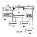
- Thisis achieved by, in essence, providing an artificial three dimensional biochemical map composed from the optical responses, or more accurately, derivatives of such responses, of each individual volume element examined in an array, and by further converting these biochemical data to an artificial pathological image delineating the nature, extent and depth of pathologies observed.
- Thisis achieved by creating an artificial pathological scale, for each pathology of interest, by training the instrument to recognize specific pathologies.
- a training set of specimens on which optical responses with a non imaging volume microprobe were collectedis subjected to a rigorous laboratory determination of the pathological state of each of its specimens and a value is assigned to each specimen on the artificial pathological scale.
- a set of linear equations relating to the responses (or functions of the responses) for each specimen to the pathological statesis constructed and optimized solutions for the correlation coefficients sought. These correlation coefficients are then used to transform responses obtained on unknown specimen to obtain the pathological state of these unknown specimen.
- the objectives of the instant inventionare achieved by providing an array of optical assemblies each consisting of two conjugated, or partially conjugated, optical assemblies.
- the first optical assemblyis designed to image selectively a transmitted beam from a light source, or another source of radiation, within a plurality of selected volume elements of a sample in a sequential manner.
- the second optical assemblyis designed to collect light, or radiation emanating from the volume elements, in the same sequential manner, and transmit the collected light or radiation to a detector for further analysis of the interaction of the first transmitted beam with the volume elements.
- the first optical assemblyincludes a first field stop to achieve selective illumination of a selected volume element, and the second optical assembly includes a second field stop to restrict acceptance of said emanating radiation or light into the collection optics, essentially only from the selected volume element.
- a controlleris provided to adjust the depth of the selected volume elements relative to the surface of the sample by controlling the respective focal points of the two optical assemblies while keeping them conjugated and having the volume element as a common conjugation point for both optical assemblies.
- Sequential illumination of the various volume elements in an arrayis desired to assure that only responses from a given volume element are collected by the optical assembly associated with the volume element at any given time.
- the sequential illumination of a plurality of volume elementsmay be carried out with a variety of devices.
- an array of optical shuttersis interposed between the light source and the sample, each shutter serving as either a field stop or an aperture stop for a specific optical assembly.
- a single array of optical shuttersis provided, while in other embodiments two arrays of optical shutters are provided.
- an array of micromirrorsis used to control the sequential illumination and response collection of the various volume elements in the sample.
- an arrayed bundle of optical fibersis used to sequentially illuminate an array of volume elements in the sample and to collect sequentially responses from the volume elements. Appropriate movement of the optics so as to probe various depths of the sample is provided.
- the optical responses from the selected volume elementsbear important information about the volume elements, such as chemistry, morphology, and in general the physiological nature of the volume elements.
- these optical responsesare analyzed by classical spectral techniques of peak matching, deconvolution or intensity determination at selected wavelengths.
- One such systemmay be the determination of the degree of homogeneity of a mixture or a solution of a plurality of compounds.
- the spectral complexityis often too great to obtain meaningful diagnosis.
- a training sample of a specific target pathologySuch a sample will preferably have at least 10 specimens.
- Optical responsesare first collected from well defined volume elements in the specimens and recorded. These optical responses may be taken with an array microprobe or with a single volume microprobe device as described in the aforementioned co-pending application.
- the same volume elements that have been sampled with the non imaging volume microprobeare excised and biopsies (namely cytological analysis of the excised volume elements) is carried out in a classical pathological laboratory and the specimens are scored on an arbitrary scale which relates to the extent of the pathology, C (for instance a specific cancer) being characterized.
- the factors a icthe correlation transform's coefficients for the pathology C, are now found from the set of equations created above, by means well known in the prior art, such as multivariate linear regression analysis or univariant linear regression analysis. In such analysis, the number of wavelength windows i required to obtain faithful correlations between the optical responses and the pathological derivations of the values C j , is minimized and the set of correlation coefficients a ic for the pathology, C are found.
- LDAlinear discriminant analysis
- QDAquadratic discriminant analysis
- RDAregularized discriminant analysis
- these responsesmay be treated optically through either a spatial Fourier transform generator (such as a Sagnac interferometer) or a temporal Fourier transform generator (such as a Michelson interferometer), and then the data obtained may be used to create the desired correlation matrices to train the system for further data acquisition and image generation of the distribution of possible pathologies.
- a spatial Fourier transform generatorsuch as a Sagnac interferometer
- a temporal Fourier transform generatorsuch as a Michelson interferometer
- Instruments embodying the inventionare deemed useful for obtaining artificial images of some characteristics of turbid materials, such as biological tissue, plastics, coatings, and chemical reaction processes, and may offer particular benefits in analysis of biological tissue, both in vitro and in vivo.
- certain embodiments of the present inventionmay be adapted to work with existing endoscopes, laparoscopes, or arthroscopes.
- the systems and methods of the present inventionmay be adapted to work within a body orifice, such as the mouth, the ear canal, or the vagina.
- the systems and methods of the present inventionmay be adapted to work within a body lumen, such as the colon or the bladder.
- the systems and methods of the present inventionmay be adapted to work within a body cavity such as the peritoneal or the pleural cavity. Other adaptations may be envisioned by ordinary skilled artisans in the field.
- the diagnostic apparatusmay be provided with a covering to insulate it from contact with biological tissues. It is an objective of the present invention to provide a protective sheath for in vivo optical diagnostic systems that may serve as a biological barrier between patient's tissue and the optical probe.
- the systems and methods of the inventionmay provide a barrier disposed external to the diagnostic probe that separates the probe from any tissue of the body, including those tissues in continuity with the target tissue sample and including those tissues adjacent to or in proximity to the tissue sample.
- a barrier according to these systems and methodsmay insulate a colposcopic probe, for example, from contact with the tissues of the cervix, vagina and vulva.
- the biological barrierbe disposable and adapted for a single use.
- the term “single use”is understood to comprise the use for a single diagnostic measurement performed by the probe. It is desirable that the barrier or disposable sheath be capable of use with only one patient. As used in only one patient, a unique individual, the biological barrier may be adapted for a single use or may be adapted for multiple uses. Systems according to the present invention are adapted to prevent the use of the probe in more than one patient.
- a sheathconstructed to conform to the optical requirements of the diagnostic systems and methods of the present invention.
- such a sheathadvantageously would provide minimal interference with the optical responses produced by tissues after their excitation by a beam of electromagnetic radiation produced by a diagnostic system according to the present invention.
- such a sheathwould include an optical window, an optical filter, a lens or a polarizer capable of being exposed to ultraviolet radiation without producing a significant fluorescent response.
- a sheathwhich may be mounted and dismounted on the optical probe with great ease and minimal training. It is an object of the invention that a sheath be equipped with an affixation mechanism that also orients the sheath on the probe in a preselected, optimal direction. It is a further object of the invention that a sheath possess mechanisms that facilitate the assurance of single use for the sheath.
- a sheathmay be provided with a mechanical affixation mechanism that is suitable only for a single use.
- the affixation mechanismmay entail damage to the attachment apparatus when the sheath is detached from the probe.
- the sheathmay be provided with an identifying marker that may be read by the probe so that the system may determine that the sheath is suitable for use.
- An identifying markermay provide data about the unused state of the sheath or data about the previous use of the sheath. It is an object of the present invention that the sheath interact with the probe to prevent the use of the probe in the absence of an unused sheath.
- a probe being used with the barriermay comprise a processing system that correlates certain data borne by the identifying marker on the sheath with an indicator that indicates or relates to an unused or a previously used state of the sheath.
- the probe to be used with the barriermay include a receptor system that receives a signal generated by a sensor on the barrier and that thereupon renders the probe operable or inoperable, depending upon the type of signal received.
- a probe rendered capable of being usedmay be termed operable or activated.
- the probemay be inoperable in the absence of an unused sheath.
- an unused sheathmay be required for a signal to be produced that activates the probe.
- the inventionmay provide a system for controlling use of a diagnostic apparatus that includes a diagnostic apparatus, a disposable sheath with an identifier that bears unique data to characterize that particular disposable sheath, a detector that produces a signal indicative of the unique data borne by the identifier, and a receiver system that responds to the signal produced by the detector, that determines the state of the disposable sheath and that provides a second signal that regulates activation of the probe.
- a signal or any other mechanism that regulates activation of the probemay activate the probe, may prevent it from being activated, or may provide any other type of regulation that affects the use of the probe.
- these systems and methodsinclude a plurality of interactions between sheath and probe whereby the integrity of the sheath and its proper use are assured.
- these systems and methodsmay comprise a database with which the probe apparatus communicates to determine the unused state of the sheath.
- these systems and methodsmay comprise a set of diagnostic tests that ensure the integrity of the sheath and its proper positioning upon the probe, or that ensure the proper positioning of the probe with respect to the patient, or that ensure the proper type of sheath be placed on the probe. It is an object of the invention to provide proper sheaths for a plurality of anatomic areas where the probe may be used, for example the cervix and the endocervix.
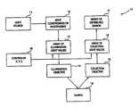
- FIG. 1is a schematic and generalized block diagram of the major elements of the present invention.
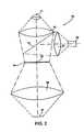
- FIG. 2is a block diagram of an embodiment of the invention with an array of light valves, in which each light valve acts as an addressable field stop for the illumination and detection beams.
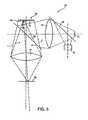
- FIG. 3illustrates an embodiment where an array of lenslets of the same periodicity as the array of light valves acts as an array of objective lens for both the illumination and detection beams.
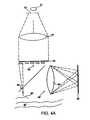
- FIG. 4 and FIG. 4Aillustrate embodiments of the invention in which separate illumination and detection light valves arrays create arrays of aperture stops, each in conjunction with lens arrays serving as objectives for the illumination and detection optics.
- the detection lens arrayis replaced with a single lens.
- FIG. 5illustrates an embodiment of the invention in which an array of (deformable) flat micromirrors is used as field stops and the sequential selection of micromirrors serves to sequentially illuminate volume elements in a sample.
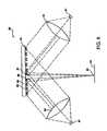
- FIGS. 6 and 6Ashow embodiments of the invention in which an array of (deformable) off axis parabolic mirrors serve as selecting objectives to sequentially apply excitation beams to various volume elements and collect the responses from the volume elements.
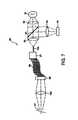
- FIG. 7shows an embodiment of the invention in which the light shutter array is replaced with a fiber switching device to sequentially illuminate (and obtain responses from) an array of volume elements in a target sample.
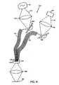
- FIG. 8illustrates an embodiment having two optical assemblies, each coupled to its own (excitation and detection) fiber bundles in which sequential illumination of fibers (and detection) is practiced to obtain data from an array of volume elements.
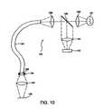
- FIGS. 9 and 10illustrate embodiments of the invention in which light shutter arrays are coupled to optical fiber bundles.
- FIG. 11is a schematic representation of one of the. embodiments of the invention, including a block diagram of the control and data processing elements of the system.
- FIG. 12is a block diagram that illustrates methods of using volume probe arrays of the invention, particularly in the diagnostic of various pathologies.
- FIGS. 13A and 13Bare bottom and top views, respectively, of a partial segment of a PVDF based optical shutter array.
- FIG. 14shows another embodiment of a PVDF based optical shutter array.
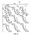
- FIG. 15is a top view of a micromachined optical shutter array.
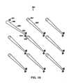
- FIG. 16shows another embodiment of a micromachined optical shutter array.
- FIG. 17is an anatomic cross-sectional view showing an embodiment of the invention positioned within a body cavity within the female perineum.
- FIG. 18shows an embodiment of a disposable sheath illustrating optical fibers therein.
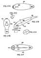
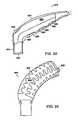
- FIG. 19A and Bshow an embodiment of an optical probe bearing a protective sheath.
- FIG. 20Ashows an embodiment of a disposable sheath disposed to cover an optical probe
- FIG. 20Bshows an embodiment of a disposable sheath in a furled position.
- FIGS. 21A-Fshow various projections of an embodiment of an optical probe system with a protective sheath in place.
- FIG. 22shows schematically an embodiment of an optical probe covered with a disposable sheath.
- FIG. 23A-Dshow embodiments of attachment mechanisms affixing a flexible portion of a protective sheath to a distal rigid portion.
- FIG. 24shows an embodiment of a protective sheath adapted for application by heat shrinking.
- FIG. 25 A and Bshow, respectively, an embodiment of a tip of a probe system adapted for examination of the endocervix, and an embodiment of a probe system adapted for examination of the endocervix.
- FIG. 1we show a generalized schematic volume probe array, 10 , whose function is to collect data from a plurality of points in a target sample.
- the systemgenerally includes an appropriate light source I 1 , whose light output is conditioned and may be multiplexed in block 12 to create a plurality of light sources to be relayed to an array 13 of light valves.
- These light valvesmay act as illuminating field stops or aperture field stops, and only one valve is open at a given time, thus providing for sequential illumination of volume elements in sample 19 .
- the light emanating from each light valveis then directed to a targeted volume element in the sample 19 with an appropriate illumination objective 14 .
- a single objective lensis used, while in other embodiments, we incorporate an array of objective microlens having the same periodicity as that of the light valve array.
- Responses from each targeted volume element in the form of light emanating from the volume elementsis collected through a collection optics objective 15 (which in some embodiments may be the same as the illumination objective and an array of microlens), and through an array 16 of light valves (which may also be the same array as the one used for illumination).
- the responsesare then directed to one or more detectors 17 to determine their optical and spectral characteristics.
- both the illumination optics and the collection opticseach contain a field stop having dimensions that are relatively large in relation to the average wavelength of the illuminating radiation, and furthermore, these field stops are conjugated to each other through the volume element examined.
- a well defined volume elementis illuminated at any time, and the optical response from the element collected through the field stop of the collection optics is essentially limited to responses emanating from the volume element.
- a controller 18is provided to control the sequencing of the volume elements scanned (in the x,y plane, the plane of the sample) and to control the depth of the volume elements examined (in the z direction.)
- FIG. 2a simple example of an array volume microprobe system 20 is shown.
- the systemincludes a light source 21 .
- Light from the light sourceis condensed with a lens 22 onto an array of light shutters 24 , through a beam splitter 25 .
- each element 28 in the light shutter arrayserves as a field stop which is being imaged through an objective lens 26 on a sample 27 .
- the dimensions and shape of the shuttersdetermine the morphology of volume elements sampled in a manner discussed in detail in U.S. Pat. No. 5,713,364.
- the mean dimension, d, of each shutteris selected to be larger than the wavelength divided by the numerical aperture, NA, of the objective of d> ⁇ /NA.
- the image of the field stop in the plane of the sampleis larger than the diffraction limited resolution for the wavelength.
- a very large proportion of the light that traverses a given field stop and is imaged in the sampleis within a well-defined volume element of the sample.
- the total response to the illuminationis distributed over a very large spatial angle (essentially 4 B steradians)
- only responses that are emanating from within the same volume elementare imaged back onto the field stop and reach detector 29 , by being reflected on the beam splitter 25 onto a collector lens 23 which concentrates the response onto the detector 29 .
- both field stopsare embodied within the same aperture (an optical shutter or a light valve 28 within the optical shutter array).
- the beam splitter 25may be a dichroic mirror, particularly when the light source is a short wavelength (UV) exciting light source and the responses are fluorescence responses.
- the beam splitter 25may be a half silvered mirror which separates the optical path of responses from the sample from the optical path of the exciting beam, for instance, when the exciting beam is provided with a broad spectrum light source, and the responses involve back scattering and reflections from the sample (and thus mostly the extent of absorption of the exciting beam in the targeted volume element is examined).
- the array of light valves, or optical shuttersmay be implemented in a number of different ways.
- ITOIndium Tin Oxide
- TOTin Oxide
- films of PDLCpolymer dispersed liquid crystals
- Another embodiment contemplated, when the required scanning is particularly fast,is an array of ferroelectric elements, each acting as a light valve.
- Yet another embodiment of the light valvesmay involve an array of PVDF (Polyvinyl-difluoride) bimorphs, each coated to be reflective (or opaque on both sides) on the side facing the light source and designed to bend out of the light path so as to create a light valve.
- PVDFPolyvinyl-difluoride
- the typical dimensions of the light valverange from a low of about 20 microns to as much as 1000 microns. The size is determined primarily by the application, the nature of the sample analyzed and the particular design of the specific array volume microprobe utilized.
- the space between adjacent light valvesis usually kept as small as possible, so as to provide as closely spaced as possible scanned volume elements. It should be understood however that in some embodiments, the spacing is kept relatively large (as large as the field stop itself) when an image of the pathology consisting of well spaced discrete points is more appropriate.
- the controller 18keeps one of the light valves open and adjusts the position of the device so as to image the field stop at the desired volume element in the sample 27 .
- the controllercauses scanning of the surface of the specimen in the xy (the plane of the specimen) direction by sequentially closing an open light valve and opening an adjacent light valve.
- the time interval of each light valve in the open positionis a strong function of the intensity of the light source and the efficiency of collection of the response from each volume element. In some embodiments, this time interval may be shorter than a millisecond, while in other embodiments tens to hundreds milliseconds are required.
- the controller 18also controls the position of the volume elements within the sample in the z direction, generally an axis perpendicular to the plane of the samples.
- the whole optical assemblymay be moved back and forth in the z direction.
- this translational movement of the image plane of the field stops in the samplemay be achieved by moving the objective alone, or the array of light valves, or both of these elements simultaneously.
- the specific designdepends on the particular embodiment of the device.
- FIG. 3a slightly different embodiment of an array volume microprobe 30 of the present invention is shown.
- the systemincludes a light source 31 with appropriate optics (not shown) to project a common field stop 41 through a condenser lens 32 onto an addressable shutter array 34 .
- Each element in the addressable shutter arraymay be considered an aperture stop which serves to further limit the spatial distribution of the light impinging on a sample 37 .
- a lens array 36is interposed between the Ishutter array and the sample.
- the lens array 36consists of a plurality of microlens 42 .
- the periodicity of the lens arrayis exactly the same as that of the shutter array, and each lens 42 within the lens array 36 corresponds to a light valve 38 within the light shutter array 34 .
- the light impinging on the shutter arraywould be collimated, and the shutter array would be fixed in position relative to the lens array.
- the volume element probedwould be at the focal point of the objective lens within the microlens array, and movement of the combination of the shutter and lens array in the z direction, may be used to probe different layers within the sample, as explained above when describing the array volume microprobe of FIG. 2 .
- Light responses to the exciting radiation from the light source 31 from each of the sampled volume elementsare collected through the same objective elements through which illumination is effected.
- the light responsesare separated from the illuminating beam by the beam splitter 35 .
- These responsesare then imaged via a collecting lens 33 onto a collection field stop 43 that restricts the responses received by a sensor 39 to be essentially only from the probed volume element.
- the controller 18opens a given shutter and allows the illumination of a single volume element. Furthermore, the same light shutter allows optical responses to the excitation to be recorded by the detector 39 .
- the illuminating and detecting opticsare each provided with their own array of optical shutters.
- FIG. 4such an embodiment is shown schematically.
- the array volume microprobe 50includes a light source 51 , a first field stop 52 , a collimating lens 53 , a first shutter array 54 , a first objective lens array 55 , beam splitting means 56 , a second objective lens array 58 , a second shutter array 59 , a second collimating lens 60 , a second field stop 61 and a detector 62 .
- Not shown in FIG. 4are appropriate means to image the light source 51 and detector 62 onto their respective field stops 52 and 61 .
- the light source 51is imaged onto the field stop 52 , having dimensions that are greater than the diffraction resolution limits of the exciting radiation.
- the light emanating from the field stop 52is collimated into an essentially parallel beam that impinges on the back side of the shutter array 54 .
- only one of the light valves in the light shutter arrayis opened and its corresponding light valve in the detector shutter array is open.
- the sequential illumination of an array of volume elements within the samplein a manner similar to that described above, coupled with the synchronous opening of the appropriate light valve in the detector array, assures that at any given time, only responses from the probed volume element are detected.
- controller 18sequencing the opening and closing of the light valves in the two shutter arrays in synchronism. It should be understood that in this embodiment, the two field stops 52 and 61 are conjugated to each other via each of the volume elements 63 in the sample 57 .
- FIG. 4Aan arrangement essentially identical to that described in FIG. 4 is shown, except that the array of microlens 58 is replaced with a single large lens 58 ′.
- Like elements in FIGS. 4 and 4Ahave the same reference numbers.
- FIG. 5shows an array volume microprobe 70 .
- the systemincludes a light source 71 and a detector 72 having their optical axes orthogonal to each other and separated by a first beam splitter 73 .
- the light emanating from the sourceis condensed onto an array of field stops 74 with a condenser lens 75 and a second beam splitter 76 .
- the array of field stops 74consists of an array of inicromirrors 77 that may be tilted in and out of a plane generally parallel to the plane of the array.
- the micromirrors 77are sequentially brought to the untilted position by the controller 18 , and as a result of this sequential untilting of micromirrors, a sequence of responses from volume elements in the sample 79 is recorded in the detector 72 . An artificial image from the responses may then be recorded and displayed.
- probing of the sample with the volume microprobe array in the z direction (depth)may be achieved by either moving the objective lens 77 or the array 74 in the z direction.
- the control of the tilting mirroris performed by controller 18 , and the tilting mechanism may be implemented in a number of ways well known in the prior art.
- the mirrorsmay be micromachined in silicon, leaving a cantilever in the middle of the back of the mirrors. Two opposing electrodes cause the mirror to tilt about the cantilever due to charging one or the other electrode with a charge opposing the charge on the mirror itself
- Another method of obtaining tilting mirrorsis well known in the art of deformable mirrors, whereby each micromirror is mounted on a bipolar piezoelectric element.
- An array volume microprobe 80includes a light source 81 from which light is conditioned to pass through a first field stop (not shown) and through a lens 82 .
- the lightis collimated onto an array of micromirrors 83 .
- the micromirrorsare tiltable as described above.
- each of the micromirrorsis shaped to be an off axis segment of a paraboloid of revolution having its focal point tracing an arc of radius which is somewhat larger than the distance of the array from the sample.
- the geometryis such that when the mirrors are untilted (parallel to the plane of the array), the axis of the paraboloid of revolution (of which the specific mirror is an off axis segment) is perpendicular to the plane of the array.
- a line between the focal point (of the paraboloid of revolution) and the micromirroris at a predetermined angle to the normal to the array.
- the micromirrorsmay be tilted through that angle so as to bring the focal point of the paraboloid onto the sample.
- the micromirrorsare arranged in alternating right rows 89 and left rows 88 of off-axis segments of a paraboloid.
- the right mirrorsmay be termed the exciting mirrors and the left mirrors the detecting mirrors.
- each segment of right rows 89upon tilting at the above mentioned angle, resides within the sample at the volume element 85 , and its respective paraboloid axis of revolution is parallel to the optics axis of the exciting beam, while the tilting in the opposing direction (at the same angle) of each mnicromirror in an adjacent left row causes the focal point of each micromirror to move to the same volume element ( 85 ) in the sample 84 , and its respective paraboloid axis of revolution is parallel with the optics axis of the detector.
- all mirrors in right rows 89are used to excite volume element 85 in the sample 84 and all left rows 88 are used to collect responses from volume element 85 .
- only one pair of mirrorsis tilted at any given time and the axes of all other mirrors point down toward the sample.
- an exciting beam from the light source 81is imaged onto the volume element 85 , or more accurately, the first field stop is so imaged, while light impinging on all other mirrors is scattered away from the sample in all directions.
- only responses emanating from the volume element 85are imaged back onto the second field stop in front of the detector.
- the controller 18controls the sequence of tilting each pair of mirrors to obtain an array of responses from different volume elements in the sample.
- the depth of the volume element in the sampleis also controlled by the controller 18 by moving the total array 83 along the z axis toward or away from sample 84 .
- FIG. 6 AA slightly modified embodiment of the volume probe array shown in FIG. 6 is presented in FIG. 6 A.
- This embodimentallows for using each off axis parabolic micromirror both as an excitation and detection mirror.
- the systemis equivalent to that shown in FIG. 6 and described above, except that the micromirrors of array 83 ′ of the volume probe array 80 ′ are rotated by 90° to the right or the left.
- the axis of revolution (and thus the optical axis) of each mirroris at 90° to the optical axis of the exciting and detecting optics.
- volume element 85 ′is determined by the overlap of the images of the two field stops, as explained in detail in U.S. Pat. No. 5,713,364. In this embodiment, as well as the one shown in FIG.
- sheared conjugation of the excitation and detection optics field stopsis used to provide for spatial discrimination of the excitation beam to the target volume element as well as the spatial discrimination of the detected responses to be essentially from each volume element.
- the controller 18causes two adjacent micromirrors ( 89 ′ and 88 ′) to be rotated simultaneously as described above and thus provides excitation of essentially only the desired volume element 85 ′ and responses which emanate essentially from the volume element 85 ′.
- An advantage of the embodiment shown in FIG. 6Ais that a higher resolution of volume elements is feasible for the same density of micromnirrors, since each mirror may be used to either excite a volume element or to collect responses from an adjacent volume element. This differs from the embodiment shown in FIG. 6, where all left mirrors may be used only to collect responses and all right mirrors may be used only to excite volume elements.
- the tilting of the off-axis paraboloids of each segmentis in a plane perpendicular to the plane of the array, while in the embodiment of FIG. 6A, the plane of rotation is parallel to the plane of the array.
- An array microprobe 90includes an illumination optical assembly with a light source 91 and a first collimating lens 92 , and a response collection optical assembly having a detector 93 and a second collimating lens 94 .
- the respective optical axes of the light source assembly and the detector assemblyare at 90° to each other.
- a beam splitter 95is positioned at the intersection of the exciting and detected beam so as to separate the detected signal from the excitation signal.
- a lens 96is used to focus the exciting beam into an optical fiber 102 which is interfaced with a fiber switching element 97 .
- the fiber switching element 97is terminated on the opposing side with a plurality of fibers 98 , and the switching element is capable of connecting optically and sequentially (under the control of the controller 18 ) the proximal fiber 102 to any of the fibers 98 in the distal bundle.
- the ends of the individual fibers in the bundleare then arranged in an array 99 (this array may be either a linear array or a two dimensional array).
- An objective lens 100then images the respective ends of the fibers in the fiber bundle onto the specimen.
- Each individual fiber end (within the fiber holder)defines a field stop which is imaged onto the sample. This field stop serves as a field stop to both the exciting beam and the detected responses from the sample.
- This field stopserves as a field stop to both the exciting beam and the detected responses from the sample.
- the fiber switching element 97directs the exciting beam sequentially through all the fibers in the bundle 98 .
- a plurality of volume elements in the sample 101(having a distribution corresponding to the array of fibers in the bundle 98 ) are excited sequentially.
- Responsesare collected through the same field stop (the natural aperture of each fiber end) and are separated from the exciting beam by the beam splitter 95 to be detected in detector 93 .
- This embodimenthas the advantage that a higher intensity of excitation is feasible, since the light source is used sequentially by the different fibers in the bundle.
- FIG. 8yet another embodiment of a volume microprobe array 110 is shown.
- the deviceincludes two optical assemblies, an excitation or source assembly 111 and a detector assembly 112 .
- Each of the assembliesis interfaced to its own individual fiber bundle 113 and 114 , respectively.
- the individual fibersare organized, in one embodiment, in two rows 116 and 117 , respectively, in a fiber holder 115 .
- the fibersare organized in two opposing rows, one row consisting of the excitation fibers in bundle 113 and the other row of detection fibers in bundle 114 .
- the fibersare organized in alternating rows of excitation fibers and detection fibers, with a small tilt of such rows relative to each other.
- the excitation optics 111includes a light source 118 and focusing optics 119 that may focus the output of the light source on each fiber in the bundle 113 sequentially.
- a rotating mirror 120is used to index the light source onto the opening apertures of the fibers in the bundle 113 .
- the input aperture of the excitation fibersmay be terminated in an appropriate way to improve collection of the light from the rotating mirror. Such termination may include, but is not limited to, flaring of the input end of the fiber, or termination of each fiber with a small compound parabolic concentrator, as is well known in the prior art.
- the controller 18causes the incremental rotation of the mirror 120 so as to direct the excitation beam to fibers in bundle 113 sequentially.
- This lightthen emanates through an excitation field stop at each distal end of the fiber, the field stop being essentially the aperture of each fiber.
- These field stopsare imaged onto a sample 124 with objective microlens at the end of each fiber.
- the distal ends of both excitation and detection fibersare terminated into microlenses that serve as objectives.
- the excitation and detection fibersmay be at a slight angle to each other, and sheared conjugation of their respective field stops (fiber apertures) defines the volume elements probed.
- the volume elements in the samplewill be a mirror image of the fiber arrangement, namely a row or an array of points, depending on the organization of the fibers in the fiber holder 115 .
- the distance between the volume elementsmay be the same as that between the fibers in the fiber holder or may differ from the interspacing of the fibers in the fiber holder, and will depend on the magnification of a relay lens 125 . In some embodiments, one may allow for movement of the relay lens relative to the fiber holder so as to provide magnification (or demagnification). However, the size of each volume element will also be modified somewhat.
- This configurationallows for the sequential illumination of an array of volume elements in sample 124 .
- An excited volume elementwill emit a response to the exciting beam.
- the responsesare collected with a dedicated fiber from bundle 114 .
- the opticsare configured such that the respective field stops of the response fibers (their natural aperture) are each conjugated to the respective the field stops of the associated exciting fiber.
- the excitation beamhas its highest intensity within the sample within the zone of sheared conjugation (the probed volume element), and the intensity declines very rapidly outside the volume element.
- responses collected by each detection fiberemanate essentially only from the volume element, and any response collected from adjacent tissues is very small relative to the response obtained from the zone of sheared conjugation of the excitation and detection field stops.
- the response opticsinclude a receiving rotating mirror 123 which directs (sequentially and in synchronism with the excitation mirror 120 ) the responses through a focusing lens 122 to a detector 121 .
- stray responsesnamely, responses emanating outside the zone of sheared conjugation and thus outside the target volume element
- stray responsesnamely, responses emanating outside the zone of sheared conjugation and thus outside the target volume element
- the use of a beam splitteris avoided, and only very simple optics are used at the distal end of the device.
- Such a deviceis particularly suitable when a distance between the sample and the optics (source and detector) is required, such as in laparoscopic and endoscopic devices.
- This embodimenthas the additional advantage that higher excitation energies are feasible, since the light source resources are not distributed simultaneously over a full array as in some embodiments described above, and in this respect is similar to the embodiment shown in FIG. 7 and described above.
- FIGS. 9 and 10two additional embodiments of the invention, which differ from each other only in the position in the system of the addressable light shutters, are shown.
- a volume microprobe array 130that includes a light source 131 , a detector 132 , and an optical fiber bundle 133 is shown.
- the proximal end of the optical fiber bundleinterfaces an addressable array of optical shutters 134 .
- the optical shuttersare under the control of the controller 18 .
- Each fiber in the bundle 113is positioned in an array arrangement that corresponds to the addressable light shutter jarray.
- the light source 131is coupled to the light shutter array via a condenser lens 135 and a shutter array coupling lens 136 .
- the devicehas objective optics 137 which essentially images each of the apertures 138 of the fibers on a sample 139 .
- the distal apertures of the fibersare, in essence, acting as the excitation and detection field stops for each of the volume microprobes in the volume microprobe array 130 of this embodiment.
- Responses to the exciting signals emitted from volume elements in the sampleare collected by the fibers through the same objective optics 137 and the same fibers through which excitation was carried.
- the excitations and responsesare limited to the individual volume elements probed by each fiber.
- the light shutter arrayis controlled by the controller 18 to sequentially open the light shutters in front of the fiber bundle sequentially in such as way that only one fiber is powered at any given time.
- the responseis separated from the excitation by a beam splitter 140 positioned at 45° to the optical axis of the excitation optics and detection optics.
- FIG. 10a similar volume microprobe array 150 is presented.
- the essential differenceis that a shutter array 154 is positioned at the distal end of the fiber bundle. This allows for selecting an array of field stops determined by each of the apertures within the shutter array rather than by the individual apertures of the optical fibers.
- a plurality of detectors corresponding to adjacent fu 1 ll regions of the shutter arrayare employed. Each detector accepts responses from a subarray of the light shutter array, and thus from the sample.
- data collectionis accelerated by the simultaneous opening of a light valve in each of the subarrays in the light shutter array and detecting the response in their respective detectors.
- careis taken to assure that interferences (or noise) from responses outside each specific region are smaller than a preset value of the expected response from the sample in each region.
- an array of light shuttersis employed to sequence the excitation of an array of volume elements in the sample as well as collect responses from the volume elements.
- each shutterserves as an excitation and detection field stop, while in other embodiments other optical elements in the system perform the function of the field stop.
- Such light shuttersare well known in the prior art and have been used in a number of display devices, whereby the sequence of opening and closing sets of optical shutters that are back illuminated provide either a fixed or a time variable image.
- the actual embodiments of such shutters in the prior artmay take many forms.
- the most widely used light shutter arrayis an array of liquid crystal elements having two sheets of polarizer one each on the front and the back of the array. On each element in the array, a voltage may be applied. When the voltage is sufficiently high, the liquid crystal causes rotation of the plane of polarization of light passing through it.
- the two polarizersare oriented in such a way that no light passes through an element when no voltage is applied. Thus, the polarizers are cross polarized (their relative orientation is 90°, thus the first polarizer removes all light polarized in one direction, while the second polarizer blocks the light passing through the then inactive liquid crystal element).
- the plane of polarization of the light passing through the liquid crystal cellis rotated, so that the second polarizer is essentially transparent to the light passing through the active liquid crystal cell.
- the addressingmay be carried out as in the prior art, either as row and columns, so that only the sum of voltages applied to both a row and column is sufficient to cause the desired rotation of polarized light. Since the dimensions of our light shutters are relatively large and the number of shutters small relative to the current practice in liquid crystal display, such addressing is quite sufficient, and cross talk is minimal and insignificant in view of the strong spatial discrimination due to the conjugation of the excitation and detection field stops.
- the shutter arrayconsists of ferroelectric elements activated in a manner similar to that of liquid crystal light shutter arrays. These shutter arrays are useful when the switching rate desired, namely, the rate of opening and closing a given light shutter in the array, is faster.
- the light switching mediumis a polymer dispersed liquid crystal (PDLC).
- PDLCpolymer dispersed liquid crystal
- a dispersion of droplets of liquid crystalis embedded in a polymer having an index of refraction equal to the field oriented index of refraction of the liquid crystal dispersion.
- the dropletsWhen no electrical field is applied, the droplets are randomly oriented and light is scattered in all directions.
- the shuttermay be considered as closed.
- a sufficiently large electric fieldis applied to a PDLC element, the liquid crystal droplets orient themselves with the field and thus, in the direction of the field, the index of refraction is essentially constant and light passes through uninterrupted.
- the shutteris open.
- essentially electromechanical shuttersare used. Such may be easily implemented with piezoelectric bimorphs, which when actuated bend out of the path of the light and when inactive, assume a straight geometry which blocks light transmission through a given shutter.
- FIG. 13Aa top view of a light shutter array 310 is shown.
- This shutter arrayconsists of two main elements, a passive base element in which an array of perforations 311 and an array 320 of active flags 321 are provided.
- the passive basemay be made of an appropriate plastic, metal or even silicon.
- the perforations 311are about 0.1 mm in diameter and are spaced on a grid in which the interspace between the perforations is about 1.0 mm. It should be understood that other dimensions may be selected without deviating from the teachings of the invention.
- the perforationswhich are preferentially slightly conical with their bases at the proximal end and their truncated apices at the distal end, serve as receptacles for optical fibers, each having an external diameter of 0.1 mm.
- optical fibersmay first be inserted and cemented in place, and then the surface of the passive base, with the fibers in place, is optically polished to ensure that the fibers are flush with the distal surface of the base and have an acceptable optical finish.
- the surfacemay then be treated with an antireflective coating so as to minimize optical reflections from the distal ends of the fibers, and thus improve both the illumination and signal collection efficiency.
- the array 320 of active flags 321consists of two sheets of piezoelectric material, such as polyvinyl difluoride (PVDF) with metallization on both sides.
- the two sheetsare first cemented together (for instance with an acrylonitrile compound).
- the metallizationis etched, leaving a pattern of rows of electrodes 323 interconnected with common leads 322 (in rows) on the top side of the pair of PVDF sheets as shown in FIG. 13 A.
- the electrodes 323have the same geometry as the flags 321 , or may be just a little smaller than the flags.
- FIG. 13Bthe bottom side of the array 320 of active flags 321 is shown.
- the metallization of the bottom sideis etched to provide second electrodes 324 for each flag, which are interconnected with leads 325 in columns.
- the flagsare formed, the electrodes being congruent on both sides (overlapping but ispaced apart by the two sheets of PVDF).
- the array of flags 321is created by punching or etching horseshoe-like perforations 326 around each of the metallized pairs of opposing electrodes in the array. It should be apparent to a person trained in the art that one may choose to first form the flags and then etch away the excess metallization between the rows and columns of electrodes.
- the application of a voltage to a row of top electrodes 323 through the common lead 322causes the top half (formed by the top PVDF sheet) of the flags 321 in that row to become shorter than in their respective unpowered state, while the application of a similar voltage (but of opposite polarity) on a column of bottom electrodes 324 via common lead 325 , causes the bottom half (formed by the bottom PVDF sheet) of the flags 321 in that column to become elongated relative to their unpowered state.
- the appropriate voltagesare applied to a specific row through conductor 328 and none other, and to a specific column through conductor 327 and none other.
- the flag 329which is the only flag at that time having both its top and bottom electrodes powered, has on its top portion a voltage that causes its top half to shorten and has on its bottom portion a voltage that causes its bottom half to elongate. As result, flag 329 bends upward and exposes the perforation under it, allowing illumination to reach the sample and allowing responses from the sample to reach the aperture of the optical fiber and thus be transmitted to the sensor. All other flags in the row powered by the row conductor 328 are devoid of voltage on their respective bottom electrodes, and, similarly, all other flags powered by the column conductor 327 are devoid of voltage on their respective top electrodes.
- PVDF flags 332are structured in a similar fashion to the system shown in FIGS. 13 a and 13 B and described above. Specifically, two sheets of PVDF are cemented back to back, and flags 332 are formed with electrodes on both sides connected on the top side in columns with leads 333 and connected on the bottom side in rows with leads 334 . This assembly is overlayed on a plate having an array of perforations 331 . The flags are oriented at 45° to the main lattice to allow for a greater movement of the flag. This is important when the fibers have very large numerical apertures and the beams emanating from the fibers.
- this arrayfollows the principles described above.
- the application of a driving voltage to a given column and a given rowcauses the actuation of the flag on that column and row.
- each bimorphhas a flag (parallel to the plane of the array and thus perpendicular to the bimorph) covering its respective perforation in the array.
- the actuation of each bimorphcauses movement parallel to the array surface rather than above the surface.
- This embodimentis somewhat more difficult to implement, but has the advantage that smaller bending of the bimorph is required, particularly when the optical fibers used in the array possess a large numerical aperture.
- FIG. 15yet another embodiment of an array of optical shutters is shown.
- the array 340is best produced by techniques of micromachining from silicon wafers. While a certain order of description of the various elements in the array is followed below, this order is not necessarily the order used in the micromachining process.
- Perforations 341through which optical fibers are inserted, are provided in an array. In this embodiment, these perforations are about 0.1 mm in diameter and are spaced on a grid of 1.0 mm spacing. Each perforation is associated with its own shutter 342 .
- the shutter 342consists of a thin flexible arm 343 anchored on one side to the base plate 344 via an axis 345 . On the opposing side of the arm, a flag 346 is provided.
- the flagis sufficiently large to cover its respective perforation 341 when the shutter is in the closed position.
- Two series of posts 347 and 348 positioned on opposite sides of the arm 343are connected to appropriate electrical leads (not shown).
- the shutter elementis connected to its own electrical lead (not shown).
- the total array of optical shuttersis manufactured monolithically from a single wafer. In that case, the arm and flag are machined to be in the “open” position 349 . Otherwise, it becomes impractical to etch the perforations.
- the arrayis produced firom two pieces cemented together. One piece may contain the array of arms, and the other piece may contain the array of perforations. Then it is preferred to have the rest position of the arms in the closed position.
- the groups of posts 347 and 348may be on either of the two wafers, but for practical reasons it is preferred to produce them on the array of arms. It is also possible to provide a single well-positioned post for the group of posts 347 and a single well-positioned post for the group of posts 348 . The choice of the specific design depends on the dynamic response required from the light shutters in the array.
- the operation of the arm as a light shutteris based on the electrostatic attraction and repulsion generated by the charging and discharging of various members of the assembly.
- the armmay be charged, for instance negatively, and the distal posts 347 may be charged positively to cause the arm to be attracted to this set of posts.
- the proximal posts 348may be charged negatively to cause simultaneous repulsion of the arm. It should be understood that actual contact of the moving arm with either group of posts 348 or 347 is not required. It is preferred to actually avoid such contact and in order to accomplish this aim, the whole assembly may be treated to have a thin layer of silicon oxide as an insulation, thus avoiding such contact.
- the activating voltagesin rows and columns, and only the simultaneous actuation of a given column and a given row causes opening of the shutter at the intersection of the selected row and column. This may be achieved in a number of ways. Consider the case where the device is made of two independent wafers, so that the rest position of the arm may be in the closed state. Thus, when no charges are present on the arm, the optical shutter is closed. Referring again to FIG. 15, apply a pulse charging all the arms in the first row negatively, and through the pair of leads for the first column, a positive charge is applied to the posts 347 and a negative charge is applied to the posts 348 .
- the negatively charged arm in the first row and the first columnis repulsed from the negatively charged posts 348 and is attracted to the positively charged posts 347 , thus opening the optical shutter previously covered by the flag 346 .
- the other arms in the first roware unaffected, since their respective posts 347 and 348 are uncharged.
- all arms in the first columnare uncharged and thus, despite the fact that the posts 347 and 348 are charged, the arms do not move, thus leaving the optical shutters closed.
- all arms 343 in a given rowmay be kept charged and the posts in adjacent columns may be sequentially charged.
- the return of the arm to its closed positionmay be achieved either through the spring forces in the arm or actively by reversing the charges on the posts 347 and 348 .
- the selection of a passive return or an active return to the closed positionis determined by the dynamics of the scanning process. When extremely rapid scanning is desired, reversal of the charges on the posts is preferred, but when the dynamic response may be slower, mechanical relaxation to the rest position may be practiced.
- FIG. 16another embodiment of a micromachined optical shutter array is shown.
- the arraymay be monolithically produced or may be assembled from two sub structures.
- an array of perforations 361having a diameter of about 0.1 mm spaced on a grid whose points have 1.0 mm spacing is provided.
- the active elementscomprise flat arms 362 attached to the base plate with a twistable post around which the arm may rotate. The distal end of the arm is sufficiently broad to cover the perforations and thus block the optical path to the fibers that are mounted within the perforations. While in FIG. 16 arms having their width gradually expanding to cover the perforation 361 are shown, it should be understood that a narrow arm 362 terminated by a wide flag at its distal end, sufficient to cover the perforation, may be provided.
- the proximal end of the armis terminated with a structure 364 generally perpendicular to the axis of the arm.
- Two posts 365protrude from the base plate, positioned somewhat apart from the structure 364 .
- the electrostatic attractioncauses the arm to rotate and expose the perforation, thus opening the optical shutter as shown in position 366 .
- the arraymay be operated by maintaining a given row (charging the arms 362 in that row) negatively and scanning the column, which positively charges all pairs of posts 365 , to obtain sequential opening and closing of the optical shutter array.
- the elastic properties of siliconmay be relied upon to return the arm to its rest position (through the twisting base 363 spring action), or the charge on the pairs of posts may be reversed before switching to the next column.
- a variety of light sourcesmay be used in conjunction with the array volume nmicroprobes of the present invention.
- a laser sourcesuch as a nitrogen laser having a wavelength in the ultraviolet part of the spectrum, such as 337 nanometers.
- the light sourceis usually a broad spectrum source such as, but not limited to, a xenon discharge lamp, a halogen incandescent lamp, or any other suitable broad spectrum light source.
- a light sourcemay be conditioned with an appropriate filter to homogenize or otherwise modify the light spectral distribution.
- a volume microprobe arraymay include a UV laser source to perform fluorescence measurements, as well as a wide band light source to perform scattering and absorption measurements.
- a third light source particularly rich in near infrared radiationmay be included as well.
- these light sourcesmay be directed toward the excitation optical assembly in a predetermined sequence.
- a typical UV laser sourcewould operate in a pulse mode having a relatively short duration pulse (for instance under a microsecond) and a slow repetition rate.
- a lapse time between excitation of milliseconds or fractions thereofis available between measurements of fluorescence responses.
- a broadband light sourcemay be directed at the excitation optics, and measurements of the response of the target sample to that second light source may be detected.
- the light source or excitation beammay then be a laser within the visible range of the spectrum.
- a laserin the far red or the near infrared part of the spectrum.
- Such light sourcesmay be a HeNe laser at 633 nm, or a GaAIAs diode or laser diode at 783 nm or even a Nd:YAG laser at 1064 nm, as well as other near infrared diodes or laser diodes.
- multiple detectorsmay be used as well. Each is designed to be optimized for the spectral response and response intensity anticipated. In such cases, the timing of the excitation from the plurality of sources and the responses from their associated detectors is controlled by the controller 18 .
- FIG. 11a typical volume microprobe array 170 with its associated electronic modules and computing modules is shown.
- the optical systemis similar to that shown in FIGS. 9 and 10 and described above, except that the beam splitter is positioned at the distal end of the optical fiber assembly, and in lieu of using the light shutter array for both the excitation and detection optics, an array of detectors is used for the spatial discrimination of the responses, rather than an array of light shutters.
- the volume microprobe 170includes a data processing and system control unit 171 and an optical system 172 .
- the optical systemincludes at least one light source 173 .
- Lenses 174 and 175are interposed between the light source and a light shutters array 176 so as to image the light source onto the array.
- a device 176may be included to condition the spectral distribution of the light source.
- a devicemay be a filter that is designed to modify the normal spectral distribution of the light source, which may include parts of the spectrum at intensities that are greater than other parts, and thus normalize the spectral distribution of the exciting beam.
- the element 176may be a plurality of filters mounted on a rotating filter wheel, so as to interpose different type of filters (or no filter) in the exciting beam path.
- a second device 177may be included to modulate the exciting beam in time and in intensity.
- Such a schememay be used to improve the signal-to-noise ratio of the detection system by synchronizing the modulation and detection through an appropriate phase locked amplifier (not shown), which is part of the electronics system 171 (indicated as control arrows 191 and 193 ).
- the timing of the light source 173is also under the control of the controller 201 as indicated by the control arrow 192 .
- the light shutter array 176is coupled to an optical fiber bundle 178 in such a manner that each fiber within the bundle is coupled to a given light shutter in the array.
- the distal ends of the fibers within the bundle 178are arranged in the same array configuration as the proximal ends so as to maintain the same array geometry.
- the aperture of the individual optical fiberdetermines the field stop of the excitation optics in this embodiment.
- the light shutters within the array 176are under the control of the controller 201 via a control line 200 , and in operation, the controller sequentially opens light shutters so as to provide an excitation beam sequentially to all fibers in the array.
- a beam driving mirror 184is provided, the function of which is to select, within the sample, the desired area from which an array of volume elements is to be analyzed.
- the tilt of the directing mirror 184is controlled by a joy stick 187 , which may be operated manually, or be under the control of the controller 201 via control line 196 .
- a beam splitter 180is utilized to separate the excitation beam from the responses. Since the illumination of volume elements within the target array is sequential, at any time, only responses from a given volume element are received by the detector assembly.
- the detector assemblycontains an array of detectors 183 , and the respective apertures of each detector element within the array also serve as the field stops of the detection optics. Since both the excitation optics and the field stops of the detection optics are conjugated within the target volume element in the sample, we ensure that detection of responses emanating essentially only from each volume element are recorded for each volume element in the sample.
- the detector assemblyalso contains additional traditional optical elements, such as a spectral filter 181 , whose function is to eliminate from the responses undesired parts of the spectrum. For instance, when the excitation beam is a nitrogen laser and the desired responses are fluorescence emissions, the filter blocks any reflections of the excitation beam and prevents their registration as responses.
- a spectral analyzer 182is also included to determine the spectral distribution of the responses.
- the detector arrayis under the control of the controller 201 via a control line 194 so as to ensure the synchronization of excitation and response detection from each volume element in the target sample.
- the detector assemblyor in some embodiments a specific element of the assembly such as an objective lens, may be caused to move in a direction parallel to the optical axis of the assembly with a driving mechanism 186 under the control of controller 201 (through control line 197 ), so as to adjust the z position, or depth, of the volume elements probed by the array microprobe system, in a manner similar to that described above.
- Signals from the detector, representing optical responses,are directed to a signal processing unit 202 , which then transfers the data to an analog to digital converter 203 for further data conditioning in a data preparation module 204 .
- the data representing responses(and tagged to assure that the processor recognizes data from various volume elements, which is achieved with a control line 199 from the controller 201 ) are then treated in a calibrator/scaler 205 to normalize the data. This is achieved by monitoring the output of the light source and renormalizing data for variations in the output of the source via line 220 .
- the control and data processing unit 171contains a memory unit 210 in which calibration and scaling constants 208 are stored as well as correlation transform matrices 209 , as further described below.
- Data from the systemare converted to diagnostic information by a computer 211 and displayed, either as diagnostic values or as artificial maps on a display station 212 .
- the computerhas memory (resident or removable) in which data may be stored and retrieved for future analysis off line.
- the inventionis intended to operate, at least partially, to record and generally also compile and analyze the responses it collects.
- only diagnostic prediction of pathologiesis provided.
- the systemis equipped with a library of correlation transform vectors or matrices for specific diagnostics, and the system only registers the signals I ij (response intensities at a specific wavelength, i, for a specific volume element j) and calculates fuinctions F(I ij ) required to provide a diagnostic score C j , for an array of volume element j, as is further described below.
- the output from detector 183is fed to a data processor 206 after preprocessing in signal processor 202 , analog to digital converter 203 and data preparation module 204 .
- Data processor 206may process the output from detector 183 or it may store the data in memory unit 210 for processing at a later time.
- the computer 211may also provide the ability to compare a first data set obtained from detector 183 with a second data set obtained from memory unit 210 , or to perform comparative studies of various volume elements within an array of volume elements measured at any given time, thus providing for spatial correlation of volume elements within a given sample.
- data processor 206may calculate correlations between a first data set representative of the material being probed and a second data set in memory unit 210 .
- the second data setmay be a library of optical response data or a mathematical model abstracted from such a library, as is more fully described below.
- Memory unit 210may be used to store a large body of data about particular materials.
- memory unit 210may store data concerning the characteristics of light which has interacted with a particular type of biological tissue, or memory unit 210 may store data concerning the characteristics of light emitted, particularly fluorescence, by particular types of biological tissues in response to excitation by each of a set of wavelengths of light, or may store such spectra indexed by tissue depth, or other complex multidimensional spectra derived from a prior set of observations.
- Memory unit 210may further store information associating particular characteristics of light obtained from a biological tissue sample with a particular diagnosis.
- the ratio of light reflected at one wavelength to light reflected at a second reference wavelengthmay be associated with cancerous tissue growth as in certain known observations, or may be associated with a clinically relevant condition such as a thickening of one layer of tissue, a precancerous metabolic change, or a malignancy, based on correlation with the spectral library and previous clinical characterizations.
- correlation with annotated or stored digitized spectramay provide a diagnostic judgment, even without the identification of any specific individual spectral features, such as peaks or absorbance bands, that have been. required for diagnosis in the past.
- the detector 183is shown accepting responses from the specimen after being treated trough a spectral analyzer 182 , it should be clear that the spectral analyzer may be replaced with either a temporal interferometer (such as a Michelson interferometer) or a spatial interferometer (such as a Sagnac interferometer).
- the resulting interferogrammay then provide the Fourier transform of the optical responses obtained from each volume element probed for subsequent data analysis as described elsewhere in this application.
- Raman spectroscopyparticularly when selecting for an excitation beam a source in the near infrared, where the intensity of the Raman scattering is greatly reduced, one may impose in the response path, in lieu of an interferometer, a Hadamard encodement mask consisting of a multi-slit array, in order to obtain via Hadamard transform of the data the Raman spectral response of the probed volume elements.
- microprobe analysis of biological tissuehas requirements that are somewhat different from those of classical microprobes. Particularly, it is not desired to have a resolution greater than the typical dimensions of differentiated tissues, but it is required to have analytical tools that may be operated by personnel without specific training in the analytical arts, such as physicians, process control personnel and other professionals.
- the use of the present inventionallows for microprobing of samples and biological tissues in vivo, and enables the spatial delineation of compositional, morphological and pathological features of such specimens.
- array volume microprobemay be used, and without limiting the scope of the instant invention, we describe herein some of these approaches.
- responses from an array of volume elementswhich represent the interactions of the material within each of said volume elements with the exciting radiation, or at least contain specific signatures of such interactions, are presented in terms of received light intensities for various wavelengths, or as is known in the art, as a spectrum of the response.
- a researcher trained in the specific analytical artmay then use these spectra to deduce important information about each of the volume elements in the array from his knowledge of the exciting radiation and the modes of interactions of the radiation with his target material.
- a variety of analytical toolssuch as software programs designed to conduct spectral peak fitting, or spectral deconvolution, may be used to further increase the researcher's basic understanding of such interactions and to provide the researcher with information on the chemical, morphological and physiological nature of the target volume elements in the array, since the responses correspond each to a specific volume element in the array probed.
- This in accordance with basic principles known in the artexcept that the data provided to the researcher are derived from a well-defined volume element and thus interferences and response weakening due to parasitic responses and interferences originating outside the target volume elements no longer hinder the researcher's ability to differentiate specific features within a largely heterogeneous sample.
- the array volume microprobe of the present inventionmay be used to perform classical spectroscopical analysis, fluorescence analysis, Raman scattering and other parametric or characterizing analysis which involves the measurement of the responses of each volume element in the array to a localized radiation while limiting the observed responses to essentially each of the volume elements in the array only at any given time.
- the systemis equipped with a library of correlation transforms dedicated to the user's special needs, so that the system is essentially pre-calibrated for specific analytical tasks.
- the method of calibrating the array volume microprobeis further detailed herein.
- a physicianwho is not a trained spectroscopist views the suspected tissues, and when discoloration or other morphological abnormalities are present, samples from such areas are excised and sent to a pathological laboratory for microscopic examination of the tissues to determine the presence or lack thereof, as well as the stage, of possible cancer.
- the array volume microprobe of the instant inventionwill enable the automated diagnostics of such viewed tissues by a physician, provide an artificial image of the pathology and its extent, without the need to examine such tissues under the microscope by another professional pathologist.
- FIG. 12is a diagram 300 showing the various steps undertaken in the calibration and then the use of the array volume microprobe.
- a training set 302 of specimens for the specific pathologyis first selected.
- the term training setwill be used herein to denote a group of tissue specimens on which very exacting cytological and pathological determination of the state of each specimen was conducted in a pathological laboratory, denoted by the step 303 .
- each specimen in the training setwas subjected, in vivo, to an exacting study with the microprobe array 301 of the present invention.
- the target volume elements in the training setare excited with both a laser UV source and a broad band white light source.
- the arrayis used with only a single shutter open, or a special single channel non imaging volume microprobe may be used.
- the volume elements in the training setare excised after recording the responses obtained with the non imaging volume microprobe, and pathological determinations of the state of each specimen are recorded in the form of scores C j , where j is the identity of the specimen and C j is a number selected according to the specimen state on a monotonic scoring scale, for instance 0 to 10, where zero denotes normal tissues and 10 fully entrenched and deep cancerous tissues. Since this training set will calibrate non imaging volume microprobes for future determinations of the presence or lack thereof of such pathologies, it is important that great care is taken at arriving at an objective determination of the pathological state of the training set. In such cases, the same samples are examined microscopically by a number of independent pathologists in a blind experiment, and only those specimens for which a minimum agreement between the various pathological results exists, are included in the training set.
- the values of I ij and J uj previously stored in memory unit 210are used to set up a set of n correlation equations (n would be the number of volume elements in the training set):
- the bandwidths around the wavelengths i and u of the responses to white light and UV light, respectively,are usually between 5 and 50 nm, depending on the spectral resolution achievable or desirable in the system's detection monochromator or spectrograph (element 182 in FIG. 11 ).
- the selection of the functions Fdepends to some extent on the nature of responses received.
- F(I ij )(dI ij /d 8 )I ij , where 8 is the wavelength.
- the functions G(M sj )are included to allow for the impact on the observed responses of the patient's specific “medical history”, and usually includes parameter such as sex, age, race, and presence or lack thereof of systemic pathologies such as hypertension, diabetes etc. In many situations, part or all the coefficient c s are nil, and these factors have no impact on the calibration, but in special cases, these factors play a role and are included here for completeness.
- a computeris now used at step 304 to perform a regression analysis to minimize the number of wavelengths i and u (and s which are “artificial wavelengths” representing medical history) used to obtain a valid correlation and to solve the set of minimized equations (1) for the correlation constants a i , b u (and c s ).
- This regression analysisis performed using the n equations obtained experimentally, using in essence the correlation constants as unknowns, for which a solution having the best correlation is sought.
- the minimizationis carried out to extract those wavelengths at which the responses contain independent relevant information that correlates the responses I ij and J uj to the scores C j .
- the methods used for obtaining the minimal set of wavelengths and the associated correlation coefficients a i and b uare well known in the prior art and include multivariant linear regression analysis and univariant linear regression analysis. Other statistical tools, such as neural networks analysis, are also available and may be used for this purpose.
- Such informationmay include general classification of the subject in which the volume element resides, such as, but not limited to sex, age, race, other systemic pathologies and weight.
- Such informationwhen its inclusion in the regression improves the confidence level of the regression, may be included as additional artificial responses R ij (in lieu of the functions G(M sj )).
- the index itherefore represents the type of response obtained, whether it is obtained with the non imaging microprobe (one or more types of responses as well as the spectral band from which the response is registered) or by other means.
- the ordered values a imay be termed the correlation vector (a) for pathology C
- the ordered responses R ijmay be termed the response vector (R j ) for volume element j in the training set.
- the functional response vector (F(R j ))is similarly defined as the ordered functions of the elements of the responses in the response vectors (R j ).
- the ordered scores C jmay be termed the pathology score vector (C) for the training set.
- the process of calibrating the array microprobe for a given pathology Cconsists therefore of obtaining all the response vectors (R j ) and their corresponding pathology score vector (C) and from these data, after generating the functional response vector (F(R j )), obtaining a minimal correlation vector (a), which is the calibration vector of the non imaging volume microprobe.
- the calibrationis identical to the calibration designed for the non imaging volume microprobe of U.S. Pat. No. 5,713,364.
- the calibration for a number of different pathologiesmay be stored in a calibration library 305 for future use on unknown specimens.
- Each microprobe arrayincludes a correlation engine 307 which may take calibration vectors from the calibration library 305 and response vectors obtained from the microprobe array and other sources such as medical records 308 and reconstruct for the response vector a value C of the observed pathology. Since in the various embodiments of the invention the different optical channels representing excitation and responses from given volume elements are equivalent, a single calibration (for a given pathology) suffices.
- the use of the calibrated microprobe array on an array of volume elements k(x,y,z), whose pathological state C k (x,y,z) is unknown,allows for the immediate and automatic diagnosis of the pathology in volume element k(x,y,z).
- This procedureis repeated for all volume elements in the array, and the set of values C k (x,y,z) for all volume elements in the array may now be presented on a display 309 , either as numerical values or as artificial images of the array examined.
- Normal methods of three-dimensional image handling and manipulationmay thus provide the physician with an insight as to the nature, extent, severity and penetration depth of suspected pathologies. This reduces the number of unnecessary biopsies required and provides the physician with immediate information on which he may act during the examination.
- the functions F(R ik (x,y,z)may be derived from the Fourier Transforms obtained from the responses, either with a temporal interferometer such as a Michelson interferometer or with a spatial interferometer such as a Sagnac interferometer. It is even possible to use the interferograms themselves in lieu of the Fourier transform generated from them. Similarly, when probing for molecular structural information on the probed elements, one uses for the functions F(R ik (x,y,z) the values at various wavelengths obtained from the Hadamard transform of the Raman spectral response.
- microprobe arrays of the inventionmay be calibrated to diagnose a plurality of pathologies P m , where m denotes a specific pathology.
- the task of calibrating the instrument for this plurality of pathologiesconsists as before of obtaining for a training set j, responses R ij and pathological scores P mj , where i is the bandwidth of the response or the type of artificial response, j is the volume element or the specimen in the training set and P mj is the score for pathology m on specimen j.
- a mcorrelation vectors
- the correlation vector (a) mentioned aboveis now replaced with a correlation matrix ⁇ a ⁇ whose elements are a im
- the functional response vector (F(R k )) for an uncharacterized specimen, kis replaced with the matrix ⁇ F(R k ) ⁇ whose elements are F(R imk ) and the diagnostic results are given as a vector (P) k whose elements are P mk by obtaining the product of the correlation matrix ⁇ a ⁇ with the functional response matrix ⁇ F(R k ) ⁇ .
- the correlation createdwill use the same responses (if not all of them at least some of them) for different pathologies.
- a response vector (R k )(having elements R ik ) is required, which includes the minimal set of responses from volume element k to obtain diagnostic scores P mk .
- the matrix ⁇ a ⁇may also be termed the correlation transform matrix, since it transforms one set of measurable (or observable) values, to another set of numbers or values, which are the desired pathological scores. This is achieved by multiplying the correlation transform matrix, ⁇ a ⁇ , with the vector (F(R k )), the functional response vector, to obtain a transformation of the response vector (R k ) to a diagnostic score vector (P) k .
- the correlation transform method exploited hereinof predicting diagnostic or analytic information on an unknown specimen by correlating optical responses of a training set to independent determination of the diagnostic or analytic data on the training set has been shown by Rosenthal to work well on artificially homogenized samples that are large enough to provide a set of responses possessing a large signal-to-noise ratio. It is surprising that the expanded method of the instant invention yields good correlation on very minuscule volume elements in vivo. In classical spectroscopy, for instance, as practiced by Alfano, spectra or optical responses of diseased tissues are compared to similar spectra or responses of healthy tissues to attempt a diagnostic reading on the target tissue. This method fails to work because of the large variations encountered between subjects and the nature of the tissue examined.
- a goal of the methodis to calibrate an array volume microprobe for the diagnosis of the presence or lack thereof of tissues that are affected by certain pathologies including cancer and that are accessible to optical visualization, either on the external skin, or in a body orifice such as the mouth or the vagina, or in other cavities that are accessible via endoscopes or laparoscopes, such as the various segments of the gastrointestinal tract or various organs in the body cavities, such as the thoracic cage and the peritoneal cavity.
- endoscopes or laparoscopessuch as the various segments of the gastrointestinal tract or various organs in the body cavities, such as the thoracic cage and the peritoneal cavity.
- the hardware probeis being used for in vivo diagnosis of biological tissues. Since the hardware probe is able to be placed into contact with.biological tissues, contamination of the optical hardware probe must be avoided. A disposable probe or a disposable covering for the optical hardware probe may be particularly advantageous in these circumstances.
- an apparatusmay be used to determine a characteristic of a sample of a biological material in an in vivo situation.
- the sample of biological materialmay exist in continuity with an in vivo body tissue of a patient.
- a barrier or a disposable sheathmay be provided to prevent the probe from contacting the biological material and from contacting the in vivo body tissue of the patient in juxtaposition to which or in proximity to which the sample of biological material is found.
- a barrier or disposable sheathmay prevent the probe from contacting those tissues that surround the in vivo body tissue wherein the sample of biological material being examined may be found.
- a barrier or disposable sheathmay entirely cover the probe; in another embodiment, a barrier or disposable sheath may cover those parts of the probe adapted for contact with a body tissue of a patient.
- sheath as used hereinis understood to encompass any device that fits over part or all of the optical hardware probe and that is thereby interposed between the probe and sample being studied or between the probe and an in vivo body tissue.
- a disposable devicemay be designed for a particular anatomic application. Procedures involving the gastrointestinal tract, the urinary tract, the peritoneal cavity, the thorax, and the female reproductive tract are examples of where a disposable device may be used. It will be especially advantageous to provide the hardware of the present invention with a disposable cover or sheath that may be adapted for use on a single patient. Furthermore, in one embodiment, the probe is constructed so that a sheath must be in place for the probe to be operable. Certain mechanisms are described in more detail below for ensuring single use of a sheath or to ensure that the probe cannot be operated without a sheath properly positioned to cover it. Other mechanisms will be readily apparent to those of ordinary skill in these arts.
- FIG. 17shows an embodiment of the apparatus of the present invention adapted for use in examining a tissue of the cervix uteri.
- An embodiment of the present inventionmay be used to examine either the external cervix or the internal cervical os.
- Embodiments of the present inventionmay be adapted for colposcopic use.
- FIG. 17shows an anatomic partial cross-sectional view of the female perineum depicting an embodiment of a disposable sheath 400 , here shown in cross-section, positioned within the vagina 408 .
- Adjacent structures including the bladder 462 , the uterus 460 , the rectum 464 and the symphysis pubis 466are shown here to facilitate orientation.
- This figureshows an embodiment in which a disposable sheath 400 may be provided for an optical hardware probe 402 to illuminate the cervix 404 .
- Configurations for the sheath 400may be adapted to the anatomy of the cervix 404 and vagina 408 .
- the white light illumination 410 of the cervix 404 for video illuminationmay be provided circumferentially.
- the distance from the distal end 412 of the probe 402 to the cervix 404may be about 100 mm.
- the probing beam 414 of the optical hardware probe 402may be transmitted through the disposable protective sheath 400 to strike the cervix 404 .
- a simple cylindrical structuremay provide an interface between the distal end of the light transmitting fibers and the disposable sheath 400 so that light is transmitted to illuminate the cervix 404 .
- an end plate (not shown) applied to the distal end 412 of the hardware probe 402may be fabricated of a material designed to minimize the fluorescence emitted from the plate when the UV excitation beam is applied.
- An example of a substance for fabricating the plateis polymethyl methacrylate (PMMA), although other optical plastics that will nnimize fluorescence may be envisioned by practitioners of ordinary skill in these arts.
- the interface between the ring on the optical hardware probe 402 bearing the optical fiber ends and the disposable sheath 400may be made from a silastic transparent material in the form of a segment of a toroid.
- a light source ring(not shown) is positioned distally just at the distal end 412 of the hardware probe 402 .
- This embodimentmay include a transparent silastic ring with a 20 degree slanted toroidal lens.
- the toroidal structuremay have a retracted snap-on mechanism that fastens the lens to the steel ring of the probe.
- the toroidal silastic elementmay be part of a highly flexible thin plastic sleeve that has a frontal membrane as its optical window.
- the thin plastic sleevemay extend proximally to wrap the hardware probe.
- Flexible plastic materialsmay include thin polyethylene films shaped conically to facilitate initial wrapping and tensioning of the frontal film. Other appropriate plastics may be envisioned by those skilled in these arts.
- a disposable sheath 400may be attached or fastened to the hardware optical probe 402 .
- a variety of fastening mechanisms 406may be envisioned by those skilled in these arts.
- a fastening mechanism 406is understood to comprise those mechanisms and systems that may affix the disposable sheath 400 to the hardware optical probe 402 .
- a simple band latching mechanismmay be employed.
- a latching mechanismmay be employed that uses a unidirectional latch.
- a plurality of pins or postsmay be placed on the hardware probe 402 . These pins or posts are positioned to align the light transmission fibers in the hardware probe 402 with the corresponding regions in the disposable sheath 400 .
- a fork-like latch on the proximal part of the disposable sheath 400may articulate with the posts so that once a post is latched into place, it may only be released by breaking the latch.
- the disposable sheath 400cannot be removed from the optical probe 402 and subsequently replaced on the probe 402 to be used for another patient.
- Other embodimentsmay be envisioned wherein the disposable probe is adapted for single patient use only. Fastening mechanisms may be envisioned by those skilled in the art that will confine the disposable probe to use on a single occasion.
- affixation mechanismsmay be devised by those of ordinary skill in these arts whereby the sheath or barrier may be detachably attached to the probe and whereby detaching the sheath or barrier prevents a subsequent use of these devices, thereby ensuring that a sheath or barrier be used only once. Certain of these affixation mechanisms are described below, but these descriptions are not intended to limit the scope of the invention as claimed herein.
- the disposable sheath 400provides a frontal window of adequate optical quality so as not to alter the optical signals passing to and from the hardware optical probe 402 .
- These featuresfurthermore adapt the device for use in a plurality of medical situations. These features render the device more useful for medical personnel in a variety of circumstances.
- the embodiments disclosed hereinare not intended to be limiting, however. Other embodiments may be envisioned by those of ordinary skill in the relevant arts.
- FIG. 18depicts the distal end 448 of one embodiment of a disposable sheath 440 according to the present invention.
- a bundle of optical fibers 442may be arranged in a ring 444 within a disposable sheath 440 .
- the distal end 448 of the disposable sheath 440may be designed according to the selection of the topology of fiber 442 arrangement.
- a ring 444may be constructed in the sheath 440 with an inner diameter of 25 mm and an outer diameter of 28 mm. This configuration may permit a number of optical fibers 442 to be placed within the ring 444 , each fiber 442 having a diameter of 1 mm.
- 78 optical fibers 442may be placed within the ring 444 arranged according to this configuration. Alternatively, spaces may be left between the optical fibers 442 in an arrangement, or optical fibers 442 may be bundled. Furthermore, the thickness of the ring 444 of optical fibers 442 may be varied to accommodate more or fewer fibers 442 . In one embodiment, the distal end 448 of the sheath 440 may be modular and alignable with the optics of the probe. Other arrangements of the optical fibers 442 in the sheath 440 will be apparent to practitioners of ordinary skill in the art. For example, a plurality of concentric rings may be constructed to contain certain of the optical fibers 442 in each ring 444 .
- the disposable sheath depicted in these figuresis shown for illustrative purposes only. A plurality of sheath configurations will be apparent to practitioners in the art whereby the sheath configuration will be suitable to the medical use envisioned for the probe. Moreover, sheath configurations may be designed by artisans of ordinary skill that will be adapted to the optical specifications of the hardware probes disclosed herein. These sheaths, in their various embodiments, will combine advantageously with the optical probe systems and methods of the present invention to permit application in a variety of clinical situations, as will be readily understood by practitioners in these arts.
- a protective sheath of the instant inventionconsists of two major elements, a frontal optical window, made for instance from cast or molded polymethylmetacrylate (PMMA), and a generally cylindrical sleeve extending from the frontal optical window to cover the optical probe, made of a thin flexible plastic such as polyethylene, the two elements are fastened at the proximal rim of the frontal optical window.
- the sleeve component of a protective sheathmay be of any shape appropriate for the anatomic area, or it may be shaped to fit a particular probe. The sleeve may be tightly applied or loosely applied to the underlying probe.
- the sleevemay be provided with gathers or folds that arrange for a particular ordering of the sleeve around the probe.
- a sleevemay be made in part from of a shrink-fitting material so as to conform more closely to the configuration of the probe. The shrinkage may be achieved either externally or by passing a small current in an embedded heating element prior to using the probe.
- a sleevemay be made of a single piece of material, or may be made of a plurality of components. A variety of sleeve arrangements will be readily envisioned by ordinary skilled artisans in this field.
- the frontal optical windowmay include a hollow cylindrical section mating with the optical distal end of the probe in a unique manner so that only one relative orientation between the probe and sheath is possible.
- Other shapes for the frontal optical windowmay be envisioned, based on the configuration of the targeted anatomic area or based on the shape of the underlying probe.
- An orientation mechanism on the sheath or on the probemay facilitate the proper positioning of the sheath on the probe, so that such positioning is easy and accurate. This orientation mechanism may further permit the reading of a marker on the sheath bearing identifying or other data by an appropriate detector, sensor or reader on the probe.
- the selection of the optical polymer used in the rigid frontal optical windowmay be related to the sort of diagnostic evaluation being performed. It is understood that certain materials have optical characteristics adapted for particular situations. For instance, in the colposcopic examination using an embodiment of the probe according to the present invention, excitation of target tissues with a UV beam is carried out and the fluorescence responses from the tissues are collected to determine potential pathologies. In this situation, the optical window of the sheath may comprise PMMA since this material has no significant fluorescent response to the excitation beam. For the purposes of this specification, a fluorescence response is termed significant when such a response interferes with the accuracy of interpreting those fluorescence responses collected from and emitted by the tissues upon being stimulated with the exciting beam.
- the end piece transmitting the UV excitation beammay be made of a very thin teflon, or may comprise other fluoroplastics such as THV-200P (a TFE/HPF/VDF terfluoropolymer from the 3M corporation). These plastics do not demonstrate a significant fluorescence response when irradiated with UV.
- the optical windowmay be combined with other optical elements, such as an optical lens, an optical filter, or an optical polarizer.
- the additional optical elementsmay be made of materials capable of transmitting electromagnetic radiation without generating a significant fluorescent response.
- a segment of the sheathmay be provided with a marker that indicates an unused state of the barrier, and the probe may be equipped with a sensor or a reader that may detect the marker.
- the sensor or readermay generate a signal capable of activating the probe. Under these circumstances, the probe may only be activated in the presence of a sheath that has not been previously used.
- a segment of the sheathmay be provided with a marker that indicates that the sheath has been previously used.
- the probeis provided with a sensor or reader that may detect the marker.
- the sensor or readermay generate a signal capable of activating the probe.
- a systemcan be arranged to prevent the use of a probe and a sheath for more than one diagnostic test cycle.
- a systemcan be arranged to prevent the use of the probe and sheath on more than a single patient, while permitting multiple diagnostic test cycles to be executed upon the one patient being examined.
- Arrangements to confine the use of the probe and sheathmay include mechanical, electronic, computer hardware or computer software systems or combinations thereof, which will can be readily devised by ordinary skilled artisans without undue experimentation.
- the sensormay detect the marker.
- the markermay be placed on an area of the optical window. However, the marker may be located on any convenient part of the sheath, with the sensor on the probe located to permit reading it.
- the markermay comprise a serial number of the specific sheath, either in the form of an actual alpha numeric marking, or in bar code form. This serial number may be “read” by a special element in the optical probe and stored in the probe's electronic system. The serial number may be correlated with other data identifying the patient being examined. Each time the probe is used to examine a patient, data is entered to identify the particular patient. In this embodiment, the serial number of a particular sheath is associated with a specific patient.
- the probemay query a database to determine if the detected serial number is already associated with a particular patient, an association that indicates a previous use of the sheath. If previous use of a sheath is discerned, the probe may be rendered inoperable. If use of the sheath on another patient is discerned, the probe may be rendered inoperable. Alternatively, the probe may be rendered operable if no previous use of the sheath is discerned, or if no previous use of the sheath on another patient is discerned. The data on the marker may be compared to any data within a database to determine prior use of the sheath or an unused state of the sheath.
- the reader on the probemay alter the marker to indicate that the sheath bearing it has been used, or may add data to the marker indicating that the sheath has been used.
- the sensormay alter or deface the data on the marker after reading it so it cannot be read again by a probe sensor.
- a sensor on the probemay interact with a marker on the sheath to determine or to indicate the used or unused state of the sheath, and furthermore to affect the activation of the probe depending upon the used or unused state of the sheath.
- Systems and methods of the present inventionmay include the detection of various conditions of the sheath.
- the condition of the sheathmay be its used or unused state.
- the condition of the sheathmay be its appropriateness for a particular type of diagnostic test. For example, a different type of sheath may be useful for screening evaluations of the cervix than would be useful for more detailed diagnostic evaluations.
- the presence of a particular type of sheathcould enable the probe system to perform a specific set of diagnostic tests.
- the condition of the sheathmay be its physical integrity, detected through a system incorporated in the sheath itself.
- the sheathmay permit a self-testing for physical integrity, the result of which produces a signal that regulates the activation of the probe.
- Self-testingmay include mechanical, hydraulic, pneumatic, electronic or any other type of test produced by the sheath itself or administered to the sheath by a separate system.
- the condition of the sheathmay be its proper positioning on the probe or in the desired anatomic region.
- the positioning of the sheath relative to the target tissuemay be validated by an orienting system, for example, that produces a signal that must be received as a precondition for activation of the probe for diagnostic examination.
- Other conditions of the sheathmay be determined by an appropriate sensor, with the generation of an appropriate signal to the probe.
- the systems of the present inventionmay permit the transmission of a number of signals relating to the condition of the sheath, each one of said signals having an effect on the regulation of the activation of the probe.
- the systems described herein to prevent the operation of the probe without the sheath in placerepresent embodiments of an interlock system.
- the sheath and the probemay bear components of an interlock system whereby the proper positioning of the sheath on the probe is needed for the probe to be used.
- An interlock systemmay incorporate a marker bearing data pertaining to the particular sheath and a reader incorporated in the probe assembly so that the reader may read the data pertaining to the particular sheath and convey a signal to the probe rendering it operational or inoperative based upon the data the marker bears.
- An interlock system according to these systems and methodsmay comprise hardware or software circuits preventing the probe from being used unless a previously unused sheath is properly positioned upon said probe.
- An electrical or electronic circuitmay be included in the optical probe system whereby the presence of a properly positioned probe is needed in order to complete the circuit and permit activation of the probe assembly.
- the proper positioning of the sheath upon the probemay release an electrically conductive fluid that would enable the activation of the probe by, for example, permitting an activation circuit to be completed or by allowing a signal to be transmitted to the probe to activate it or to deactivate a system preventing use of the probe.
- Proper positioning of the sheath upon the probemay release an electrically insulating fluid that may block an inactivation system on the probe, thereby activating it.
- the proper positioning of the sheath upon the probeincludes the positioning of a latch mechanism whereby a fastening component on the sheath interdigitates with a fastening component on the probe, thereby completing a circuit or transmitting an electrical signal that activates the probe.
- a latch mechanismwhereby a fastening component on the sheath interdigitates with a fastening component on the probe, thereby completing a circuit or transmitting an electrical signal that activates the probe.
- At least a portion of the sleeveis made to mate with a feature of the optical probe.
- a featuremay be disposed upon the external aspect of the probe, to correspond with an element of the sleeve.
- a recessed groovemay be positioned on the external aspect of the probe, into which a longitudinal bar of plastic material on the inner surface of the sleeve is pressed fit.
- the element on the sheath that mates with its counterpart on the probemay be constructed so it will break when detachment of the sheath takes place, preventing a subsequent attachment of the sheath to a probe.
- the sleeve materialmay be weakened around the mating structure on the sleeve, so that it tears away at the weakened area when it is detached from the probe.
- an index-matching liquidthat improves the interface between the probe's distal end and the sheath's end optical element, is provided, but may be used only once, thus creating another safeguard against multiple uses of the same sheath on a plurality of subjects.
- the interlock mechanisms disclosed in the present specificationmay be applied to any system where the mating of a first component with a second component must be properly performed in order for the first component to be activated.
- the systems and methods disclosed hereinmay be applied to any disposable sheath that is applied to a probe to provide a barrier between the probe and a feature of the environment in proximity to the probe.
- a disposable sheath according to these systems and methodsmay prevent contact between the probe and a body fluid in a biological environment.
- a disposable sheath according to these systems and methodsmay prevent contact between the probe and any substance making up the probe's environment.
- a probemay be used to diagnose a tissue immersed in a fixation solution which may have a damaging effect on the probe if it were to contact the probe.
- a disposable sheathmay be used to prevent contact between the probe and the inimical environment.
- a probe used in industrial settingsmay be placed in various environments where contact between the probe and a feature of the environment might be damaging to the probe or might interfere with the probe's accuracy.
- a disposable sheath as disclosed hereinmay be used to protect the probe from such contact.
- such a disposable sheathmay also comprise a single-use mechanism whereby the single use of the disposable sheath is assured.
- a single-use mechanismmay include an affixation mechanism whereby the barrier may be attached to the probe and whereby, upon detachment, the barrier is prevented from being re-used.
- the single-use mechanismmay include an interlock system that recognizes the proper position of the barrier on the probe and that prevents the probe from being used without the barrier in the proper position.
- Other embodiments of the single-use mechanismmay be envisioned by practitioners of ordinary skill in the relevant arts.
- FIG. 19Ashows a perspective view and FIG. 19B shows a cross-sectional view of an embodiment of an optical probe covered with a biological isolation barrier or disposable sheath.
- FIG. 19Ashows generally an embodiment of an optical probe system 500 comprising an optical probe 506 covered with a disposable sheath 502 .
- the sheath 502is shown here as including two elements, a rigid distal optical element 504 and a flexible thin sleeve 508 that may be gathered or wrapped at different locations on the probe 506 .
- the term distalas applied herein to a medical device, is understood to refer to that aspect of a device closest to the target tissue being examined; the distal aspect of the device is generally also furthest away from the operator.
- the probe 506may consist of a cylindrical body 510 containing certain optical elements, for example a CCD (not shown) for imaging, or optical wave guides (not shown) to facilitate transmission of excitation beams to target tissues and the transmission back of responses from a target tissue to the main console.
- CCDcompact disc-read only memory
- optical wave guidesnot shown
- Other shapes for the probe and its bodymay be readily envisioned by those of ordinary skill in the art.
- diagnostic signalsare emitted and received through the distalmost portion of the disposable sheath 502 , here shown as comprising the rigid distal optical element 504 .
- the rigid distal optical element 504itself may be a hollow cylindrical structure designed to mate with the distal end of the probe 506 .
- the rigid distal optical element 504may have at its distal end an optical window 514 .
- the optical window 514may be fabricated in a plurality of shapes and may be provided with additional optical properties.
- the probe 506may terminate proximally with a connector 518 that facilitates attachment of the probe 506 with a coupling 520 that provides an electromagnetic connection between the probe 506 and the main instrument console (not shown) of the diagnostic system.
- the connector 518 and the coupling 520may have both optical and electrical signal terminations and interconnections allowing for a remote data processing unit to be used to analyze the raw data generated and accumulated by the optical probe 506 .
- the remote data processing and analysis unitsmay also be provided with appropriate displays to present graphically the results of diagnostic tests carried out on a patient, and further may be provided with input mechanisms whereby additional data may be entered into the system pertaining, for example, to the unique identification of the particular patient being examined.
- the data processing facilities of the present inventionmay furthermore be in communication with remote data sources or databases to provide additional information or data sets to be compared to the data entered into the diagnostic system in real time or with time delay.
- the sheath 502may be provided with a proximal fastener 522 and a distal fastener 524 deployed on each side of the coupling 520 and the connector 518 .
- the fastenersmay be elastic bands, or strings within the sheaths, or hook and loop type fasteners (e.g., VelcroTM), adhesive tapes or glues, or other mechanisms familiar to ordinary practitioners in the relevant arts.
- the rigid distal optical element 504may be provided with an internal ridge 528 that mates with an appropriate groove 544 channeled on the outer aspect of the distal portion of the probe 506 . Mating the internal ridge 528 with the corresponding groove may assure that the sheath 502 is affixed to the probe 506 in a unique direction, thereby aligning an identifying marker 530 on the sheath 502 with a reader (not shown) on the probe.
- FIG. 19Bshows a cross-section of the embodiment depicted in FIG. 19A taken at the level indicated by the line X-X′. In FIG. 19B, an arrangement of the optical probe 548 to the rigid optical distal element 542 of the sheath is shown.
- a tongue 540is borne on the inner aspect of the rigid optical distal element 542 .
- a groove 544is borne on the outer aspect of the probe 548 .
- the insertion of the tongue 540 in the groove 544may align a marker 550 disposed on the inner aspect of the rigid optical distal element 542 with a reader 552 disposed on the outer aspect of the optical probe 548 .
- Other types of aligning arrangementswill be readily apparent to those ordinary skilled practitioners in these arts, arrangements whereby a particular alignment of sheath and probe is urged, thereby permitting the alignment of other elements on the sheath with corresponding elements on the probe.
- a marker 530is shown disposed on the inner aspect of the rigid distal optical element 504 of the sheath 506 . It is understood that a variety of markers may be contemplated without departing from the spirit and scope of the claimed invention, and that a variety of sensors or receptors may be disposed upon the probe that are adapted for recognizing the data borne by the marker.
- the marker 530 or the marker 550is disposed on the edge of the optical window.
- the markers 530 and 550may be a serial number or any other marker uniquely identifying the specific sheath used with a unique patient. It is further understood that the markers 530 and 550 and the reader may be disposed upon any convenient segment of the sheath and the probe.
- the markermay be placed upon the sleeve so that its data are read into the optical system prior to inserting the optical probe within the sleeve.
- the marker and the readermay each be positioned on the lateral aspect of the sheath and the probe respectively.
- the side of the probemay be equipped with an infrared light emitting diode and an infrared sensor and reflection from a series of lines printed on the side of the sleeve (such as a bar code system of marking), which are read by the sensor to identify the specific sleeve's serial number.
- a bar code system of markingsuch as a bar code system of marking
- the markers 530 and 550may be used to identify the patient on whom the measurement was taken. This specific identification number may be permanently stored in the optical system main console as a number which if seen again by the probe, will prohibit, or lock out the probe functions.
- the data on the markermay be associated in a database with data identifying the unique patient, so that the probe bearing that marker may only be used with that particular patient.
- the readermay affect the state of the data encoded on the marker so that the data are not readable subsequently. If a probe reads a set of data from a sheath marker before the probe may be used, the probe may then each time be placed in contact with a fresh sheath whose data are available for reading.
- the marker 530 on the sheath 508may be read before the use of the optical probe 508 and before the probe system 500 may be positioned in contact with a patient's tissue. This may be accomplished, for instance by requiring the probe to be armed as “ready” for use in the patient prior to each measurement. In order to arm the probe and make the probe ready for use, the operator mounts the sheath upon the probe in the correct position and the probe then interrogates the marker on the probe to compare the identifying data contained therein with a database consisting of all previously used identity numbers, to verify that the number is indeed an unused number.
- the probe system 500determines that the marker 530 on the sheath 506 bears previously unread data, corresponding to a previously unused state, the probe may be armed and be thereupon made ready for use. This ready state of the probe may also depend upon the readiness of other system parameters as well. A display integral with the controls of the system may then show the cause for “unreadiness” of the probe. Conditions causing unreadiness of the probe may include previous use of a sheath, absence of a sheath, malposition of a sheath, mechanical problems with a sheath or any other condition of the probe system 500 deemed to interfere with its safe and effective use in the diagnosis of a patient.
- the probe system 500may include conventional circuits to permit self-testing and self-diagnosing to ascertain the readiness of various components and functions necessary for safe and effective accomplishment of the diagnostic intervention.
- an RFID (radio frequency identification device) chipmay embedded in each disposable sheath, to be read by an appropriate transponder in the optical head. It should be clear that other active semiconductor devices (typically powered by the probing or querying beam from the transponder) may be used in this manner as well.
- passive electromagnetically read patterns providing codingare feasible as well and are included within the scope of the present invention.
- a marker on a sheathmay also convey information to the probe about the kind of use for which the sheath is intended.
- the kind of sheath employedmay be varied depending upon the type of diagnostic information that is desired.
- the colposcopic probemay operate in three independent modalities, and for each modality, a unique type of disposable sheath is best suited for that function.
- the term “colposcopic probe” as used hereinrefers to an optical probe system according to the present invention used for the evaluation of the tissues of the cervix. In a highly precise modality of use, a colposcopic probe may be used by highly trained physicians as a device aiding in standard colposcopy.
- a sheath employed with the probe as an aid to colposcopymay be adapted for transmitting both natural images of the relevant anatomy and signals according to these systems and methods indicating the presence or absence of particular cervical pathologies.
- the sheathmay be adapted to the optimal performance of these functions.
- the marker on the sheathmay convey to the probe information about the nature of the particular intended use of the probe. Upon receiving this information, the probe may adjust for performing the necessary functions.
- a colposcopic probemay be used to carry out “ASCUS Triage.”
- ASCUSis an acronym understood in the art to stand for “Atypical Squamous Cells of Undetermined Significance”.
- image generation of the cervixis a less important function for the probe and thus another type of disposable sheath would be used.
- the marker on the sheathmay inform the probe of the type of test, here ASCUS triage, to be carried out so that the probe may be adjusted or calibrated (typically automatically) for this specific function.
- the probemay be employed as a adjunct to the current “Pap Smear” test, intended to examine the patient's cervix for cellular abnormalities that may require subsequent detailed analysis, but not intended to provide a diagnosis of the abnormalities detected.
- This use for the probemay be a binary “pass/no pass” test, or a “yes/no” test, typically carried on by personnel with relatively little medical training.
- This use modality of the colposcopic probemay allow for screening large populations of subjects; only those returning a result of “yes” or “no pass” are directed to subsequent more detailed examination by highly trained personnel.
- a sheath adapted for this screening functionmay bear a marker with data “informing” the colposcopic probe of the specific function (“screening”) that is going to be carried out, so that the probe may be adjusted for that specific purpose.
- the coding marker of the sheathmay identify the test for which the sheath is intended and may communicate with the probe to ensure that its settings are compatible with the intended function. If the sheath is used for an unintended purpose, the interaction of the marker and the reader may interfere with the activation of the probe, as described above. A marker may simultaneously bear additional information about the specific sheath, so that a single use for the sheath may be ensured, as previously described.
- FIG. 20Ashows a lateral view of an embodiment of a disposable sheath illustrating certain features.
- a coded area 570is shown as part of a sheath apparatus 572 .
- the coded areamay be a bar code borne on the inner aspect of the flexible sheath.
- Other arrangementsmay be envisioned whereby the coded area 570 would be incorporated in the structure of a sheath 578 itself, or displayed in any other way to make it accessible to a sensor apparatus (not shown) of the probe.
- only a sensoris used and the reading is accomplished by detecting changes in ambient light reaching the sensor as the sleeve is passed over the side of the probe, and the coded area 570 imparts such light modulation then translated into a unique identifier of the specific sheath used.
- FIG. 20Bdepicts an embodiment where the sheath apparatus 572 includes a flexible sheath 578 to which a residual stress curl has been imparted, so that the flexible sheath 578 may be packaged in the form of a toroid.
- FIG. 20Bfurther illustrates an embodiment where the rigid distal element 574 is attached to the flexible sheath 578 , and the flexible sheath 578 may be uncurled to cover the probe (not shown).
- the rigid distal element 574is first adjusted on the distal end 584 of the optical probe, using, for instance, two or more indexing pins 580 which fit into grooves 582 shown with dashed lines in the illustration.
- the grooves 582may also serve to fasten the rigid distal element 574 to the distal end 584 of the optical probe in a bayonet like fashion. After the elements are secured, the curled sleeve 578 may be rolled back over the probe. At the conclusion of the procedure, the sleeve 578 may be rolled back to its original toroidal shape, assuring that no external surface of the sleeve comes in contact with the surface of the probe.
- the indexing grooves 582 and mating pins 580also ensure the alignment of the optical path of the sheath with that of the probe. This arrangement may further align the optical path of the sheath with that of the probe, and may serve to align a marker on the sheath with a sensor on the probe as previously described.
- the flexible sheath 578may be provided at its proximal end with a hollow termination 588 within which a string 590 is positioned. After deployment of the sheath 578 onto the optical probe, the string 590 may be pulled tight, to close the proximal end of the sheath and thereby to ensure that the sheath apparatus 572 does not become detached from the optical probe during the procedure.
- the string 590may be provided with periodic protrusions or beads 592 that act as ratchets or locks that hold the cinched purse-string in position.
- the distal edge of the hollow termination 588may be either perforated or weakened along a line of weakness 594 .
- the string 590is pulled in the direction of its axis to close the proximal end of the sheath 578 , but after the procedure is completed the string 590 is pulled strongly in a direction perpendicular to its axis, thus causing breakage and release of the proximal hollow termination, permitting the sheath 578 to be rolled distally over the probe.
- the string 590may be fastened to one end of the hollow termination 588 so that pulling and breaking the string 590 through the hollow termination 588 both breaks the hollow termination 588 and provides a point from which the sheath 578 may be pulled off the probe without contaminating the probe's external surface.
- FIG. 20Afurther shows that the disposable sheath apparatus 572 is suitable for an optical colposcopic probe wherein the sheath 578 may be attached to the probe by one or more mating elements 568 that may fit within one or more grooves 566 on the probe.
- the sheathmay be pulled over the probe in a manner whereby one or more mating elements 568 disposed on the inner aspect of the sheath 578 may be aligned over a matching set of grooves 566 on the outer aspect of the probe.
- the user thereuponexerts external pressure upon the mating element 568 to press fit it into the corresponding groove 566 .
- the mating element 568is disengaged so that the sheath may be removed and discarded.
- the cross section of the mating element 568may be made asymmetric so that pulling it out of its groove causes the sheath 578 to tear on the weaker side of the mating element along a tear line 598 . This would permit easier removal of the sheath and would further ensure that no reuse of the disposable sheath would occur.
- FIG. 21A-Fvarious projections of a an embodiment of an optical probe, 600 , and in particular, an embodiment adapted for use in examining the cervix uteri.
- an embodiment of an optical probe adapted for this usehave been disclosed elsewhere herein.
- FIG. 21 Ais a posterior view of an optical probe system 600 showing the probe handle 604 with a switch 610 visible distally along the handle 604 and with a connector assembly 608 deployed at the proximal end of the handle.
- the handle 604may be designed ergonomically to permit secure grasping by the operator, and it may further be adapted for the anatomic region being examined.
- the handle 604may also bear within it or on its surface components of the optical probe system 600 related to the specific diagnostic functions of the probe system 600 itself.
- FIG. 21 Bshows a lateral view of the optical probe system 600 showing the angulation 624 of the device distal to the handle 604 to facilitate anatomic access of the distal optical head 602 to the cervix.
- the optical probeitself is covered by a tightly adherent sheath 618 shown to be cut away before providing coverage for the distal optical head 602 of the probe 600 .
- an affixation mechanism 612is shown on the probe, comprising a protrusion and a groove into which the protrusion may be inserted.
- the protrusionmay be provided on the inner aspect of the sheath 618 while the groove is provided on the outer aspect of the probe; the opposite arrangement is also possible.
- Either arrangement of groove and protrusionmay comprise an affixation mechanism 612 that permits the alignment of the sheath 618 on the probe in a particular predetermined orientation.
- FIG. 21Cshows in more detail a switch 610 here shown to be located on the posterior aspect of the optical probe system 600 at the angulation of the device.
- the position of the switch 610is selected for ease of use by the operator and may assume any appropriate position on the device.
- the presence of a switch 610is optional, and other mechanisms for operating the optical probe system 600 may be envisioned by those of ordinary skill in these arts. Without being limiting, examples for such a switching mechanism may include a floor switch or a voice activation system.
- FIG. 21Dshows a cross section of the probe handle 604 taken along the line X-X′, illustrating the oval shape 620 of the handle 604 in the depicted embodiment.
- This oval shape 620has the advantage of facilitating handling of the device and rendering more consistent the orientation of the probe with respect to the cervix.
- FIG. 21Eshows a top view of an embodiment of an optical probe system 600 .
- This figuredepicts the body 622 of the probe distal to the angulation (not shown), with the distal optical head 602 located distal thereto.
- a switch 610is positioned on the body 622 for convenient operator access.
- FIG. 21Fshows an anterior view of an embodiment of an optical probe system 600 , providing an anterior view of the distal optical head 602 .
- a ring of optical fibers 628may be seen disposed along the circumference of the distal optical head.
- the ring of optical fibers 628is operably connected in certain embodiments to structures of the disposable sheath (not shown) to permit the transmission of light from the ring of optical fibers 628 through the disposable sheath to reach the tissues of the patient being examined.
- This figurefurther depicts an affixation system 614 here shown as a linear arrangement disposed along the anterior aspect of the probe handle 604 . It is understood that a plurality of other affixation systems are encompassed as embodiments of the claimed invention, and certain of these systems may be readily envisioned by those of ordinary skill in the art.
- an embodiment of an optical probe system 670is shown schematically.
- the systemincludes an optical probe 650 and a protective sheath 652 .
- the protective sheath 652may be formed as a composite of two elements, a frontal optical quality element 654 and a thin flexible sleeve 658 .
- the protective sheath 652is disposable and is intended for a single use.
- Various mechanisms of attachment between the sheath 652 and the probe 650are contemplated by the systems and methods disclosed herein.
- the flexible sleeve 658may be provided with a series of internal protrusions 660 that may be press fit into corresponding slots 666 on the probe 650 .
- the optical quality element 654may bear at its distal end a window 662 .
- the optical quality element 654may bear an affixation mechanism for securing it relative to the distal end of the probe 650 .
- the window 662may be flat.
- the window 662may be shaped to act as an active optical component integral to the optics of the optical probe system 670 .
- the window 662 or the optical quality element 654may be segmented so that a portion of the structure is flat (and thus optically passive) while other portions may be curved, forming, for example, lens segments.
- the distal optical quality element 654may be shaped as a hollow cylinder that mates with a comparably structured optical head of the probe. It is desirable for the distal part of the probe and the optical quality element 654 of the sheath 652 to be similarly shaped so that a close fit between the two may be achieved.
- the shape of these structures in cross-sectionmay be cylindrical, oval or any shape adapted to carrying out the functions of the optical probe system 670 or adapted to carrying out a diagnostic evaluation of a particular anatomic site.
- the optical quality element 652may be molded or cast from an optical plastic, such as PMMA, polystyrene or polycarbonate. These materials may be used to form the window 662 while other materials are used to form the optical quality element 652 .
- PMMAis a particularly advantageous material for these constructions because it has minimal fluorescence response when illuminated with the UW excitation beam.
- FIG. 23A-Dshow cross-sectional diagrams of embodiments of attachments by which a flexible part of a protective sheath may be affixed to a rigid distal part.
- FIG. 23Ashows an end piece 700 of a protective sheath configured as a hollow structure closed at its distal end with a distal optical window 702 .
- a thin flexible sheath 704is shown fastened to the external part of the proximal end of the end piece 700 by a fastening ring 708 that is disposed circumferentially around the end piece 700 .
- This fastening ring. 708may be “press fit” onto the proximal end locking the flexible sheath 704 between it and the end piece 700 .
- Other arrangementsmay also be envisioned.
- a thin threaded areamay be provided on the inner side of the fastening ring 708 that mates with an opposing thread on the end piece 700 , locking an edge of the flexible sheath 704 therebetween.
- FIG. 23Bshows another embodiment of an optical end piece 710 terminated with a lens structure 712 bearing an inner flat surface 706 .
- the illustrated optical end piece 710is configured as a hollow structure shaped to mate with the distal end of the optical probe.
- the fastening of the of the flexible sheath 716 to the optical end piece 710is achieved with a toroidal ring 714 that is adapted to fit within a circular concavity 718 around the circumference of the exterior aspect of the optical end piece 710 , capturing the edge of the flexible sheath 716 therebetween.
- FIG. 23Cshows an embodiment of the sheath system in which a rigid optical element 720 is fastened to a flexible sheath 722 with an appropriate adhesive 724 .
- An appropriate adhesivemay comprise various chemical compositions, for example, any of a variety of cyano-acrylate compounds that are biocompatible. Other adhesive compounds may be envisioned by practitioners in the relevant arts.
- This figurefurther shows a lens 728 that may serve as the objective for the optical probe.
- FIG. 23Dshows a cross-sectional view of another embodiment of the distal end of the disposable sheath of the present invention.
- the optical probe 726is provided with illuminating fibers 736 arranged circumferentially and abutting the circular proximal end 732 of the distal optical element 730 of the disposable sheath system.
- the bundle of illuminating fibers 736may be arranged in a ring within the optical probe 726 to emerge and terminate at a correlative area of the optical element 730 of the disposable sheath system.
- the illuminating fibers 736may terminate at a circumferential structure on the distal optical element 730 where the proximal flexible portion (not shown) of the disposable sheath system is affixed to the distal optical element 730 .
- the wall thickness of the distal optical element 730may be fairly thick (between 0.5 mm and 2.0 mm), so that a wall 734 is formed that may act as an optical waveguide to transmit light emitted from the illuminating fibers 736 to the distal end of the distal optical element 730 .
- the wall 734 of the distal optical element 730ends as a toroidal segment 738 of an optical waveguide which acts to direct the light onto the target tissues for better visualization.
- the end piece 740 of the distal optical element 730may be shaped to achieve various optical purposes, for example, acting as an objective for the probe's optical assembly.
- a space 742is shown that may contain a bead or other delivery apparatus for dispensing a fluid. The fluid is released by the mating of the distal part of the probe with the distal optical element 730 of the sheath system. The fluid may flow between the distal part of the probe and the inner aspect of the distal optical element 730 .
- the fluidmay have an index of refraction matching that of the elements in the probe and the end piece 740 .
- this space 742may occupy the top half of the inner distal circumference of the distal optical element 730 .
- a bead or other container residing in the space 742may be caused to to break and discharge its fluid, which then spread downward by capillary forces to fill the space between the inner aspect of the end piece 740 and the distal end of the optical probe.
- Other dispensation systems for a fluidmay be readily envisioned. The presence of a fluid between these two components may serve a variety of optical functions, for example, reducing sharply any reflections from the surfaces of the end piece 740 . Other functions for the fluid may be envisioned by ordinary practitioners in these arts.
- One advantage of delivering a fluid to flow between the optical prove and the distal optical elementis the prevention of reuse of the disposable sheath, because the fluid necessary for the proper functioning of the optical probe system is discharged from its reservoir upon the mating of a probe with a sheath, and the fluid may therefore only be used once, with the mating of a specific sheath with the probe.
- FIG. 24depicts an embodiment of a disposable sheath 800 provided with a flexible heat shrinkable sleeve 802 .
- the shrinkable sleeve 802may be treated with a heat source such as a hair drier after being placed upon an optical probe, thereby to shrink it.
- a resistor pattern 804may be placed on the disposable sheath 800 , for example by silk screening. With a resistor pattern in place, the sheath 800 may be treated by passing a current into a connector 808 for a short period of time, thereby heating the sheath 800 and causing its shrinkage. Shrink-fitting the sheath 800 to the probe after positioning it thereupon may stabilize the sheath with respect to the underlying probe.
- any necessary alignments between the sheath 800 and the probemay be established and maintained.
- Shrink-fittingmay also require a tearing or other destruction of the sheath 800 to remove it from the probe at the end of a procedure. A sheath 800 destructively removed may subsequently be unusable.
- FIG. 25Ais shown yet another embodiment of a disposable sheath 850 according to the present invention.
- This embodimentprovides a configuration of its distal optical element 852 adapted for evaluating pathologies of the endocervix. It is understood that, since the cervical os is typically closed, examination of its inner wall is not possible with direct surface viewing.
- the illustrated embodimentprovides an optical extension 854 for the distal optical element 852 , said optical extension being adapted for penetrating into the endocervix to permit the acquisition of diagnostic data for the tissues lining the endocervix.
- the optical extension 854terminates in a distal tip 858 comprising a tapered end capable of penetrating the usually closed cervical os and further comprising an optical system adapted for visualization of the lateral endocervical walls. Certain structures in the optical extension 854 are shown in more detail in FIG. 25 B.
- FIG. 25Bshows the distal tip 858 of the optical extension with its distalmost tapered end 862 .
- An optical system 860 within the distal tip 858comprises a faceted and mirrored cone 864 .
- the cone 864has a half angle of 45 degrees.
- a light beam 866as shown in FIG.
- the number of facets on the faceted cone 864corresponds to the number of excitation fibers used for the procedure, a number that typically is less than the number of fibers used for examining the entire surface of the cervix. It may be desirable to add an additional objective 870 to focus the excitation light beams 866 appropriately on the optical system 860 of the optical extension 854 .
- skilled practitioners in the relevant artsmay readily envision other optical systems for directing the illuminating light to the endocervical tissues and for collecting the light emanating therefrom.
- the disposable sheath 850may be mounted on an optical probe adapted for examination of the cervix uteri. If a disposable sheath 850 is selected that is adapted for endocervical examinations, a marker (not shown) on that sheath 850 may be read by the optical probe. Data from that marker may be input into the probe system, operating to activate a selected number of excitation fibers (not shown). In one embodiment, the activated fibers may provide UV light for excitation. In one embodiment, the excitation fibers may be activated sequentially, or may be activated as “opposing pairs” to assure that fluorescence responses from different spots on the wall of the endocervix are not interfering with each other.
- Optical responses from the illuminated tissuesmay be collected along the same optical path traced by the excitation beams, except that the responses are much broader (in essence lambertian in nature).
- the collection optics for the responsemay be separate from the excitation optics, or may be part of the same apparatus as the excitation optics.
- the mirrored cone 864may be a simple conical structure without facets.
- both the probe and sheathmay have shapes other than those shown in the depicted embodiments, and may be made of any suitable materials.
- the sheathmay be formed from one or more than one components adapted to the optical functions of the probe and the anatomic location where it will be used. Other shapes of the sheath may be envisioned that fit the probe appropriately.
- a number of mechanismsmay be constructed which lend themselves to limiting sheath use to a single use, some of which have been illustrated herein.
- Other mechanisms for ensuring a single use of the sheathmay include affixation mechanisms, marker and reader mechanisms, fluid dispensing mechanisms, tearing and breaking mechanisms and other mechanisms adapted for this purpose. Such mechanisms will be familiar to those of ordinary skill in the relevant arts.
- the systems and methods of the present inventionmay collect data or may relate to data pertaining to the examination procedure itself
- the system according to the present inventionmay measure and record information about the duration of the procedure, the amount of energy or other consumable supplies utilized to perform the procedure, the number of measurements taken during the procedure, or any other features of the procedure of significance.
- the systems and methods of the present inventionmay interface with a database wherein such data are stored.
- the procedure and its durationmay be tallied and correlated with patient information so that an appropriate bill for the service may be constructed.
- Billing informationmay be entered into a database that can then be accessed by the system to produce a bill for the particular procedure.
- the billing informationmay include a diagnostic or a procedural code for categorizing the procedure so that a bill bearing this information may be generated that will then be associated with a schedule of predetermined fees.
- Diagnosis according to ICD-9 codes and procedural terminology according to CPT codesare well-known in the art.
- Other codes or categoriesmay be used for organizing a patient's billing information, so that each procedure according to these systems and methods will generate an accurate bill.
- Billing informationmay differ from one patient to the next according to the fee schedules for various managed care organizations and third-party payors.
- the systems and methods of the present informationmay comprise the entry of billing information for a particular patient into a database. The billing information may then be correlated with data about the procedure itself or with data about the diagnosis produced in order to generate an accurate bill.
Landscapes
- Health & Medical Sciences (AREA)
- Life Sciences & Earth Sciences (AREA)
- Physics & Mathematics (AREA)
- Surgery (AREA)
- General Health & Medical Sciences (AREA)
- Pathology (AREA)
- Biomedical Technology (AREA)
- Medical Informatics (AREA)
- Molecular Biology (AREA)
- Engineering & Computer Science (AREA)
- Animal Behavior & Ethology (AREA)
- Biophysics (AREA)
- Public Health (AREA)
- Veterinary Medicine (AREA)
- Heart & Thoracic Surgery (AREA)
- Radiology & Medical Imaging (AREA)
- Nuclear Medicine, Radiotherapy & Molecular Imaging (AREA)
- Optics & Photonics (AREA)
- Spectroscopy & Molecular Physics (AREA)
- Chemical & Material Sciences (AREA)
- Analytical Chemistry (AREA)
- Biochemistry (AREA)
- General Physics & Mathematics (AREA)
- Immunology (AREA)
- Investigating, Analyzing Materials By Fluorescence Or Luminescence (AREA)
Abstract
Description
Claims (14)
Priority Applications (9)
| Application Number | Priority Date | Filing Date | Title |
|---|---|---|---|
| US09/481,762US6826422B1 (en) | 1997-01-13 | 2000-01-11 | Spectral volume microprobe arrays |
| AU53323/00AAU768940B2 (en) | 1999-06-09 | 2000-06-09 | An optical probe accessory device for use in in vivo diagnostic procedures |
| PCT/US2000/016014WO2000074556A2 (en) | 1999-06-09 | 2000-06-09 | An optical probe accessory device for use in in vivo diagnostic procedures |
| CA002375168ACA2375168A1 (en) | 1999-06-09 | 2000-06-09 | An optical probe accessory device for use in in vivo diagnostic procedures |
| JP2001501097AJP2003501124A (en) | 1999-06-09 | 2000-06-09 | Optical probe accessory device for use in in vivo diagnostic procedures |
| US09/591,706US6847490B1 (en) | 1997-01-13 | 2000-06-09 | Optical probe accessory device for use in vivo diagnostic procedures |
| EP00938257AEP1182964A2 (en) | 1999-06-09 | 2000-06-09 | An optical probe accessory for use in in vivo diagnostic procedures |
| US10/701,123US20040186382A1 (en) | 1997-01-13 | 2003-11-04 | Spectral volume microprobe arrays |
| US11/018,665US20050159646A1 (en) | 1997-01-13 | 2004-12-21 | Optical probe accessory device for use in in vivo diagnostic procedures |
Applications Claiming Priority (4)
| Application Number | Priority Date | Filing Date | Title |
|---|---|---|---|
| US08/782,936US6104945A (en) | 1995-08-01 | 1997-01-13 | Spectral volume microprobe arrays |
| US11537399P | 1999-01-11 | 1999-01-11 | |
| US09/241,806US6411835B1 (en) | 1997-01-13 | 1999-02-02 | Spectral volume microprobe arrays |
| US09/481,762US6826422B1 (en) | 1997-01-13 | 2000-01-11 | Spectral volume microprobe arrays |
Related Parent Applications (1)
| Application Number | Title | Priority Date | Filing Date |
|---|---|---|---|
| US09/241,806Continuation-In-PartUS6411835B1 (en) | 1995-08-01 | 1999-02-02 | Spectral volume microprobe arrays |
Related Child Applications (3)
| Application Number | Title | Priority Date | Filing Date |
|---|---|---|---|
| US09/591,706Continuation-In-PartUS6847490B1 (en) | 1997-01-13 | 2000-06-09 | Optical probe accessory device for use in vivo diagnostic procedures |
| US10/701,123ContinuationUS20040186382A1 (en) | 1997-01-13 | 2003-11-04 | Spectral volume microprobe arrays |
| US11/018,665Continuation-In-PartUS20050159646A1 (en) | 1997-01-13 | 2004-12-21 | Optical probe accessory device for use in in vivo diagnostic procedures |
Publications (1)
| Publication Number | Publication Date |
|---|---|
| US6826422B1true US6826422B1 (en) | 2004-11-30 |
Family
ID=33458492
Family Applications (2)
| Application Number | Title | Priority Date | Filing Date |
|---|---|---|---|
| US09/481,762Expired - Fee RelatedUS6826422B1 (en) | 1997-01-13 | 2000-01-11 | Spectral volume microprobe arrays |
| US10/701,123AbandonedUS20040186382A1 (en) | 1997-01-13 | 2003-11-04 | Spectral volume microprobe arrays |
Family Applications After (1)
| Application Number | Title | Priority Date | Filing Date |
|---|---|---|---|
| US10/701,123AbandonedUS20040186382A1 (en) | 1997-01-13 | 2003-11-04 | Spectral volume microprobe arrays |
Country Status (1)
| Country | Link |
|---|---|
| US (2) | US6826422B1 (en) |
Cited By (74)
| Publication number | Priority date | Publication date | Assignee | Title |
|---|---|---|---|---|
| US20020132261A1 (en)* | 2000-01-28 | 2002-09-19 | Dorsel Andreas N. | Multi-featured arrays with reflective coating |
| US20030139672A1 (en)* | 2000-05-06 | 2003-07-24 | Cane Michael Roger | Apparatus and methods for analysing epithelial tissue histology |
| US20040077951A1 (en)* | 2002-07-05 | 2004-04-22 | Wei-Chiang Lin | Apparatus and methods of detection of radiation injury using optical spectroscopy |
| US20040206914A1 (en)* | 2003-04-18 | 2004-10-21 | Medispectra, Inc. | Methods and apparatus for calibrating spectral data |
| US20050008253A1 (en)* | 2003-07-10 | 2005-01-13 | Joseph Rozgonyi | Method and apparatus for eliminating irrelevant luminescent signals |
| US20050164160A1 (en)* | 2000-08-22 | 2005-07-28 | Evotec Oaiag | Method and device for the measurement of chemical and/or biological samples |
| US20050215861A1 (en)* | 2000-09-26 | 2005-09-29 | Fuji Photo Film Co., Ltd. | Endoscope system having multiaxial-mode laser-light source or substantially producing multiaxial-mode laser light from single-axial-mode laser light |
| US20050228293A1 (en)* | 2004-03-30 | 2005-10-13 | Eastman Kodak Company | System and method for classifying in vivo images according to anatomical structure |
| US20060166383A1 (en)* | 2005-01-22 | 2006-07-27 | Samsung Electronics Co., Ltd. | Semiconductor substrate having reference semiconductor chip and method of assembling semiconductor chip using the same |
| US7127282B2 (en) | 1998-12-23 | 2006-10-24 | Medispectra, Inc. | Optical methods and systems for rapid screening of the cervix |
| US7136518B2 (en) | 2003-04-18 | 2006-11-14 | Medispectra, Inc. | Methods and apparatus for displaying diagnostic data |
| US20060258933A1 (en)* | 2005-05-10 | 2006-11-16 | Advanced Clinical Solutions, Inc. | Method of defining a biological target for treatment |
| US20060264760A1 (en)* | 2005-02-10 | 2006-11-23 | Board Of Regents, The University Of Texas System | Near infrared transrectal probes for prostate cancer detection and prognosis |
| WO2006126194A1 (en)* | 2005-05-24 | 2006-11-30 | Stryker Gi Ltd. | Tracking of disposable components |
| US20070011899A1 (en)* | 2005-07-18 | 2007-01-18 | Seagate Technology Llc | Sensing contact probe |
| US7187810B2 (en) | 1999-12-15 | 2007-03-06 | Medispectra, Inc. | Methods and systems for correcting image misalignment |
| US20070059760A1 (en)* | 2002-02-21 | 2007-03-15 | Dorsel Andreas N | Multi-featured arrays with reflective coating |
| US20070058246A1 (en)* | 2003-04-11 | 2007-03-15 | Peter Westphal | Microscope arrangement |
| US20070097446A1 (en)* | 2005-10-27 | 2007-05-03 | Harris Rodney C | Imaging system and method to change field depth |
| WO2006135628A3 (en)* | 2005-06-09 | 2007-06-07 | Chemimage Corp | Cytological methods for detecting a disease condition such as malignancy by raman spectroscopic imaging |
| WO2007011571A3 (en)* | 2004-05-05 | 2007-06-07 | Chemimage Corp | Digitizing biology |
| US20070161876A1 (en)* | 2005-11-18 | 2007-07-12 | Spectrx, Inc. | Method and apparatus for rapid detection and diagnosis of tissue abnormalities |
| US7260248B2 (en) | 1999-12-15 | 2007-08-21 | Medispectra, Inc. | Image processing using measures of similarity |
| US20070206186A1 (en)* | 2006-03-06 | 2007-09-06 | Manish Sharma | Capillary based optical measurement system |
| US7282723B2 (en) | 2002-07-09 | 2007-10-16 | Medispectra, Inc. | Methods and apparatus for processing spectral data for use in tissue characterization |
| FR2901029A1 (en)* | 2006-05-12 | 2007-11-16 | Mauna Kea Technologies Soc Par | DEVICE AND METHOD FOR ENDOSCOPY FOR SIMULTANEOUS OBSERVATION OF SEVERAL ZONES OF INTEREST. |
| US7310547B2 (en) | 2002-07-10 | 2007-12-18 | Medispectra, Inc. | Fluorescent fiberoptic probe for tissue health discrimination |
| US7309867B2 (en) | 2003-04-18 | 2007-12-18 | Medispectra, Inc. | Methods and apparatus for characterization of tissue samples |
| US20070299313A1 (en)* | 2003-04-29 | 2007-12-27 | Mcgrath Matthew J | Laryngoscope With Means to Restrict Re-Use of Blades |
| WO2008027448A3 (en)* | 2006-08-30 | 2008-05-22 | Visionscope Technologies Llc | Portable imaging system employing a miniature endoscope |
| WO2008081384A1 (en)* | 2006-12-28 | 2008-07-10 | Koninklijke Philips Electronics N.V. | Spectroscopy measurements |
| WO2008016734A3 (en)* | 2006-04-27 | 2008-08-21 | Mesosystems Technology Inc | System and method for optical detection of aerosols |
| US7469160B2 (en) | 2003-04-18 | 2008-12-23 | Banks Perry S | Methods and apparatus for evaluating image focus |
| US20090234228A1 (en)* | 2008-03-17 | 2009-09-17 | Or-Nim Medical Ltd. | Apparatus for non-invasive optical monitoring |
| US7591780B2 (en) | 2002-03-18 | 2009-09-22 | Sterling Lc | Miniaturized imaging device with integrated circuit connector system |
| US20090253967A1 (en)* | 2001-10-19 | 2009-10-08 | Visionscope Technologies, Llc | Portable imaging system employing a miniature endoscope |
| US20100034743A1 (en)* | 2008-08-08 | 2010-02-11 | Chemlmage Corporation | Raman Characterization of Transplant Tissue |
| US20100033717A1 (en)* | 2008-08-08 | 2010-02-11 | Chemimage Corporation | Raman Chemical Imaging of Implantable Drug Delivery Devices |
| US7787939B2 (en) | 2002-03-18 | 2010-08-31 | Sterling Lc | Miniaturized imaging device including utility aperture and SSID |
| US7812944B1 (en)* | 1999-04-27 | 2010-10-12 | Carl Zeiss Jena Gmbh | Array for optical evaluation of an object array |
| US20100262378A1 (en)* | 2004-05-05 | 2010-10-14 | Chemlmage Corporation | Cytological Analysis by Raman Spectroscopic Imaging |
| US7835074B2 (en) | 2007-06-05 | 2010-11-16 | Sterling Lc | Mini-scope for multi-directional imaging |
| US20110004447A1 (en)* | 2009-07-01 | 2011-01-06 | Schlumberger Technology Corporation | Method to build 3D digital models of porous media using transmitted laser scanning confocal mircoscopy and multi-point statistics |
| US7942814B2 (en) | 2001-10-19 | 2011-05-17 | Visionscope Technologies Llc | Miniature endoscope with imaging fiber system |
| US7969659B2 (en) | 2008-01-11 | 2011-06-28 | Sterling Lc | Grin lens microscope system |
| US8038602B2 (en) | 2001-10-19 | 2011-10-18 | Visionscope Llc | Portable imaging system employing a miniature endoscope |
| US8047053B2 (en) | 2007-05-09 | 2011-11-01 | Icx Technologies, Inc. | Mail parcel screening using multiple detection technologies |
| US20110288418A1 (en)* | 2008-04-02 | 2011-11-24 | The Trustees Of The University Of Pennsylvania | In vivo measurement of mitochondrial function |
| US20120108942A1 (en)* | 2010-10-27 | 2012-05-03 | Commissariat A L'energie Atomique Et Aux Energies Alternatives | Sterile Protective Membrane with Light Guides for a Medical Probe and Associated Method of Production |
| US8173431B1 (en) | 1998-11-13 | 2012-05-08 | Flir Systems, Inc. | Mail screening to detect mail contaminated with biological harmful substances |
| US8243274B2 (en) | 2009-03-09 | 2012-08-14 | Flir Systems, Inc. | Portable diesel particulate monitor |
| US20120281218A1 (en)* | 2005-01-24 | 2012-11-08 | The Board Of Trustees Of The Leland Stanford Junior University | Optical analysis system and approach therefor |
| US8311788B2 (en) | 2009-07-01 | 2012-11-13 | Schlumberger Technology Corporation | Method to quantify discrete pore shapes, volumes, and surface areas using confocal profilometry |
| US8317689B1 (en) | 1999-09-13 | 2012-11-27 | Visionscope Technologies Llc | Miniature endoscope system |
| US8486735B2 (en) | 2008-07-30 | 2013-07-16 | Raytheon Company | Method and device for incremental wavelength variation to analyze tissue |
| US8614768B2 (en) | 2002-03-18 | 2013-12-24 | Raytheon Company | Miniaturized imaging device including GRIN lens optically coupled to SSID |
| US8690762B2 (en) | 2008-06-18 | 2014-04-08 | Raytheon Company | Transparent endoscope head defining a focal length |
| US8717428B2 (en) | 2009-10-01 | 2014-05-06 | Raytheon Company | Light diffusion apparatus |
| US8725477B2 (en) | 2008-04-10 | 2014-05-13 | Schlumberger Technology Corporation | Method to generate numerical pseudocores using borehole images, digital rock samples, and multi-point statistics |
| US8828028B2 (en) | 2009-11-03 | 2014-09-09 | Raytheon Company | Suture device and method for closing a planar opening |
| US9060704B2 (en) | 2008-11-04 | 2015-06-23 | Sarcos Lc | Method and device for wavelength shifted imaging |
| US9144664B2 (en) | 2009-10-01 | 2015-09-29 | Sarcos Lc | Method and apparatus for manipulating movement of a micro-catheter |
| US20150343560A1 (en)* | 2014-06-02 | 2015-12-03 | Fracturelab, Llc | Apparatus and method for controlled laser heating |
| US9304271B2 (en)* | 2012-02-29 | 2016-04-05 | Schott Ag | Connecting element for connecting a fiber-optic light guide to a light source one time and detaching the fiber-optic light guide from a light source one time |
| US9433468B2 (en) | 2013-10-04 | 2016-09-06 | Tidi Products, Llc | Sheath for a medical or dental instrument |
| US9581723B2 (en) | 2008-04-10 | 2017-02-28 | Schlumberger Technology Corporation | Method for characterizing a geological formation traversed by a borehole |
| US20170084046A1 (en)* | 2014-02-24 | 2017-03-23 | Rambus Inc. | Optical flow sensing and pattern recognition with anti-symmetric phase gratings |
| US20170105680A1 (en)* | 2013-12-05 | 2017-04-20 | Biosense Webster (Israel) Ltd. | Dynamic mapping point filtering using a pre-acquired image |
| US9661996B2 (en) | 2009-10-01 | 2017-05-30 | Sarcos Lc | Needle delivered imaging device |
| US10436716B2 (en)* | 2014-09-24 | 2019-10-08 | Smiths Detection, Inc. | Ubiquitous transmissive raman spectroscopy for stand-off detection |
| US10579959B2 (en) | 2014-09-10 | 2020-03-03 | Cerner Innovation, Inc. | Intelligent routing of radio-frequency identification data |
| US11478151B2 (en) | 2011-12-14 | 2022-10-25 | The Trustees Of The University Of Pennsylvania | Fiber optic flow and oxygenation monitoring using diffuse correlation and reflectance |
| US11559186B2 (en) | 2015-08-13 | 2023-01-24 | Hoya Corporation | Evaluation value calculation device and electronic endoscope system |
| US11571108B2 (en) | 2015-08-13 | 2023-02-07 | Hoya Corporation | Evaluation value calculation device and electronic endoscope system |
Families Citing this family (73)
| Publication number | Priority date | Publication date | Assignee | Title |
|---|---|---|---|---|
| US6380751B2 (en) | 1992-06-11 | 2002-04-30 | Cascade Microtech, Inc. | Wafer probe station having environment control enclosure |
| US5345170A (en) | 1992-06-11 | 1994-09-06 | Cascade Microtech, Inc. | Wafer probe station having integrated guarding, Kelvin connection and shielding systems |
| US6232789B1 (en) | 1997-05-28 | 2001-05-15 | Cascade Microtech, Inc. | Probe holder for low current measurements |
| US5561377A (en) | 1995-04-14 | 1996-10-01 | Cascade Microtech, Inc. | System for evaluating probing networks |
| US5914613A (en) | 1996-08-08 | 1999-06-22 | Cascade Microtech, Inc. | Membrane probing system with local contact scrub |
| US6002263A (en) | 1997-06-06 | 1999-12-14 | Cascade Microtech, Inc. | Probe station having inner and outer shielding |
| US6256882B1 (en) | 1998-07-14 | 2001-07-10 | Cascade Microtech, Inc. | Membrane probing system |
| US6578264B1 (en) | 1999-06-04 | 2003-06-17 | Cascade Microtech, Inc. | Method for constructing a membrane probe using a depression |
| US6445202B1 (en) | 1999-06-30 | 2002-09-03 | Cascade Microtech, Inc. | Probe station thermal chuck with shielding for capacitive current |
| US6838890B2 (en) | 2000-02-25 | 2005-01-04 | Cascade Microtech, Inc. | Membrane probing system |
| US6914423B2 (en) | 2000-09-05 | 2005-07-05 | Cascade Microtech, Inc. | Probe station |
| US6965226B2 (en) | 2000-09-05 | 2005-11-15 | Cascade Microtech, Inc. | Chuck for holding a device under test |
| WO2002028273A2 (en)* | 2000-10-06 | 2002-04-11 | Yang Victor X D | Multi-spectral fluorescence imaging and spectroscopy device |
| DE20114544U1 (en) | 2000-12-04 | 2002-02-21 | Cascade Microtech, Inc., Beaverton, Oreg. | wafer probe |
| DE10119543A1 (en)* | 2001-04-21 | 2002-10-24 | Philips Corp Intellectual Pty | Arrangement for magnetic resonance signal optical transmission has electrooptical modulator material between crossed polarizers so light extinguished if no voltage induced in coil |
| US7355420B2 (en) | 2001-08-21 | 2008-04-08 | Cascade Microtech, Inc. | Membrane probing system |
| US6777964B2 (en) | 2002-01-25 | 2004-08-17 | Cascade Microtech, Inc. | Probe station |
| KR100864916B1 (en) | 2002-05-23 | 2008-10-22 | 캐스케이드 마이크로테크 인코포레이티드 | Probes for Testing Devices Under Test |
| US6847219B1 (en) | 2002-11-08 | 2005-01-25 | Cascade Microtech, Inc. | Probe station with low noise characteristics |
| US6724205B1 (en) | 2002-11-13 | 2004-04-20 | Cascade Microtech, Inc. | Probe for combined signals |
| US7250779B2 (en) | 2002-11-25 | 2007-07-31 | Cascade Microtech, Inc. | Probe station with low inductance path |
| US6861856B2 (en) | 2002-12-13 | 2005-03-01 | Cascade Microtech, Inc. | Guarded tub enclosure |
| US7221172B2 (en) | 2003-05-06 | 2007-05-22 | Cascade Microtech, Inc. | Switched suspended conductor and connection |
| US7492172B2 (en) | 2003-05-23 | 2009-02-17 | Cascade Microtech, Inc. | Chuck for holding a device under test |
| US7057404B2 (en) | 2003-05-23 | 2006-06-06 | Sharp Laboratories Of America, Inc. | Shielded probe for testing a device under test |
| US7250626B2 (en) | 2003-10-22 | 2007-07-31 | Cascade Microtech, Inc. | Probe testing structure |
| WO2005065258A2 (en) | 2003-12-24 | 2005-07-21 | Cascade Microtech, Inc. | Active wafer probe |
| US7187188B2 (en) | 2003-12-24 | 2007-03-06 | Cascade Microtech, Inc. | Chuck with integrated wafer support |
| WO2005121824A2 (en) | 2004-06-07 | 2005-12-22 | Cascade Microtech, Inc. | Thermal optical chuck |
| US7330041B2 (en) | 2004-06-14 | 2008-02-12 | Cascade Microtech, Inc. | Localizing a temperature of a device for testing |
| KR101157449B1 (en) | 2004-07-07 | 2012-06-22 | 캐스케이드 마이크로테크 인코포레이티드 | Probe head having a membrane suspended probe |
| EP1789812A2 (en) | 2004-09-13 | 2007-05-30 | Cascade Microtech, Inc. | Double sided probing structures |
| DE102004059526B4 (en)* | 2004-12-09 | 2012-03-08 | Sirona Dental Systems Gmbh | Measuring device and method according to the basic principle of confocal microscopy |
| US7535247B2 (en) | 2005-01-31 | 2009-05-19 | Cascade Microtech, Inc. | Interface for testing semiconductors |
| US7656172B2 (en) | 2005-01-31 | 2010-02-02 | Cascade Microtech, Inc. | System for testing semiconductors |
| US7449899B2 (en) | 2005-06-08 | 2008-11-11 | Cascade Microtech, Inc. | Probe for high frequency signals |
| JP5080459B2 (en) | 2005-06-13 | 2012-11-21 | カスケード マイクロテック インコーポレイテッド | Wideband active / passive differential signal probe |
| US20120302892A1 (en)* | 2005-07-25 | 2012-11-29 | Niyom Lue | Portable optical fiber probe-based spectroscopic scanner for rapid cancer diagnosis |
| US7705307B1 (en)* | 2006-02-27 | 2010-04-27 | Agiltron Corporation | Thermal displacement-based radiation detector of high sensitivity |
| US7609077B2 (en) | 2006-06-09 | 2009-10-27 | Cascade Microtech, Inc. | Differential signal probe with integral balun |
| US7723999B2 (en) | 2006-06-12 | 2010-05-25 | Cascade Microtech, Inc. | Calibration structures for differential signal probing |
| US7403028B2 (en) | 2006-06-12 | 2008-07-22 | Cascade Microtech, Inc. | Test structure and probe for differential signals |
| US7764072B2 (en) | 2006-06-12 | 2010-07-27 | Cascade Microtech, Inc. | Differential signal probing system |
| US7443186B2 (en) | 2006-06-12 | 2008-10-28 | Cascade Microtech, Inc. | On-wafer test structures for differential signals |
| US20080012578A1 (en)* | 2006-07-14 | 2008-01-17 | Cascade Microtech, Inc. | System for detecting molecular structure and events |
| CN103815860A (en)* | 2006-07-21 | 2014-05-28 | 昂科斯科公司 | Protective probe tip, particularly for use on fiber-optic probe used in endoscopic application |
| DE102006050886B4 (en)* | 2006-10-27 | 2016-12-22 | Siemens Healthcare Gmbh | Medical instrument and device for generating tissue sections |
| US7705309B1 (en)* | 2007-02-27 | 2010-04-27 | Agiltron Corporation | Radiation detector with extended dynamic range |
| US7876114B2 (en) | 2007-08-08 | 2011-01-25 | Cascade Microtech, Inc. | Differential waveguide probe |
| CA3194784A1 (en) | 2008-05-20 | 2009-11-26 | University Health Network | Device and method for fluorescence-based imaging and monitoring |
| US9055866B2 (en)* | 2008-06-27 | 2015-06-16 | Olympus Corporation | Internal observation device for object having light scattering properties, internal body observation device, endoscope for internal observation and internal observation method |
| US7888957B2 (en) | 2008-10-06 | 2011-02-15 | Cascade Microtech, Inc. | Probing apparatus with impedance optimized interface |
| US8410806B2 (en) | 2008-11-21 | 2013-04-02 | Cascade Microtech, Inc. | Replaceable coupon for a probing apparatus |
| US8319503B2 (en) | 2008-11-24 | 2012-11-27 | Cascade Microtech, Inc. | Test apparatus for measuring a characteristic of a device under test |
| US8717417B2 (en) | 2009-04-16 | 2014-05-06 | Primesense Ltd. | Three-dimensional mapping and imaging |
| US20120232408A1 (en)* | 2009-11-30 | 2012-09-13 | Laura Ann Weller-Brophy | Method and Apparatus for Cervical Cancer Screening |
| KR20130056886A (en)* | 2010-06-25 | 2013-05-30 | 노스이스턴 유니버시티 | Method for analyzing biological specimens by spectral imaging |
| US9025850B2 (en) | 2010-06-25 | 2015-05-05 | Cireca Theranostics, Llc | Method for analyzing biological specimens by spectral imaging |
| US9030528B2 (en)* | 2011-04-04 | 2015-05-12 | Apple Inc. | Multi-zone imaging sensor and lens array |
| WO2013001805A1 (en)* | 2011-06-29 | 2013-01-03 | 株式会社ニコン | Structured illumination optical system and structured illumination microscope device |
| US8878920B2 (en)* | 2011-07-12 | 2014-11-04 | Karl Storz Imaging, Inc. | Method and apparatus for protection from high intensity light |
| US20140012137A1 (en)* | 2012-07-06 | 2014-01-09 | Robert Rosen | Hand-Held Dual-Magnification Dermatoscope |
| CN105593651B (en)* | 2013-08-02 | 2019-06-07 | 威利食品有限公司 | Spectrometric system and method, spectroscopy equipment and system |
| JP6769949B2 (en) | 2014-07-24 | 2020-10-14 | ユニバーシティー ヘルス ネットワーク | Data collection and analysis for diagnostic purposes |
| DE102014014872A1 (en)* | 2014-10-06 | 2016-04-07 | Dräger Safety AG & Co. KGaA | System for transcutaneous determination of blood alcohol concentration |
| US10460439B1 (en) | 2015-08-12 | 2019-10-29 | Cireca Theranostics, Llc | Methods and systems for identifying cellular subtypes in an image of a biological specimen |
| US20170209027A1 (en)* | 2016-01-26 | 2017-07-27 | Muruga Raj | Measurement device |
| JP6786424B2 (en)* | 2017-03-13 | 2020-11-18 | 株式会社モリタ製作所 | 3D scanner |
| DE102017115922C5 (en)* | 2017-07-14 | 2023-03-23 | Precitec Gmbh & Co. Kg | Method and device for measuring and setting a distance between a machining head and a workpiece and associated method for regulation |
| WO2019217735A1 (en)* | 2018-05-11 | 2019-11-14 | Arizona Board Of Regents On Behalf Of The University Of Arizona | Low-cost, compact chromatic confocal module |
| US10905309B2 (en)* | 2019-03-19 | 2021-02-02 | Reed Cam, Inc. | Method and apparatus for enforced provisioning and compliant usage authorization of endoscope applications |
| US11707182B2 (en)* | 2021-03-24 | 2023-07-25 | PacificMD Biotech, LLC | Endoscope and endoscope sheath with diagnostic and therapeutic interfaces |
| WO2023064274A1 (en) | 2021-10-11 | 2023-04-20 | Rce Technologies, Inc. | Calibration system and method for spectroscopic devices |
Citations (205)
| Publication number | Priority date | Publication date | Assignee | Title |
|---|---|---|---|---|
| US3013467A (en) | 1957-11-07 | 1961-12-19 | Minsky Marvin | Microscopy apparatus |
| US3632865A (en) | 1969-12-23 | 1972-01-04 | Bell Telephone Labor Inc | Predictive video encoding using measured subject velocity |
| US3809072A (en) | 1971-10-07 | 1974-05-07 | Med General Inc | Sterile sheath apparatus for fiber optic illuminator with compatible lens |
| US3890462A (en) | 1974-04-17 | 1975-06-17 | Bell Telephone Labor Inc | Speed and direction indicator for video systems |
| US3963019A (en) | 1974-11-25 | 1976-06-15 | Quandt Robert S | Ocular testing method and apparatus |
| US4017192A (en) | 1975-02-06 | 1977-04-12 | Neotec Corporation | Optical analysis of biomedical specimens |
| US4071020A (en) | 1976-06-03 | 1978-01-31 | Xienta, Inc. | Apparatus and methods for performing in-vivo measurements of enzyme activity |
| US4198571A (en) | 1977-04-28 | 1980-04-15 | National Research Development Corporation | Scanning microscopes |
| US4218703A (en) | 1979-03-16 | 1980-08-19 | Bell Telephone Laboratories, Incorporated | Technique for estimation of displacement and/or velocity of objects in video scenes |
| US4254421A (en) | 1979-12-05 | 1981-03-03 | Communications Satellite Corporation | Integrated confocal electromagnetic wave lens and feed antenna system |
| US4273110A (en) | 1978-07-13 | 1981-06-16 | Jean Groux | Ultraviolet endoscope |
| US4357075A (en) | 1979-07-02 | 1982-11-02 | Hunter Thomas M | Confocal reflector system |
| US4397557A (en) | 1979-12-20 | 1983-08-09 | Heimann Gmbh | Optical arrangement for a light scattering type smoke detector |
| EP0135134A2 (en) | 1983-08-11 | 1985-03-27 | Vitacomm Ltd | Esophageal stethoscope and vital signs monitor system |
| US4549229A (en) | 1982-02-01 | 1985-10-22 | Sony Corporation | Method and apparatus for compensating for tape jitter during recording and reproducing of a video signal and PCM audio signal |
| SU1223092A1 (en) | 1984-03-11 | 1986-04-07 | Предприятие П/Я Р-6681 | Small-angle nephelometer |
| US4646722A (en) | 1984-12-10 | 1987-03-03 | Opielab, Inc. | Protective endoscope sheath and method of installing same |
| US4662360A (en) | 1984-10-23 | 1987-05-05 | Intelligent Medical Systems, Inc. | Disposable speculum |
| US4733063A (en) | 1985-12-13 | 1988-03-22 | Hitachi, Ltd. | Scanning laser microscope with aperture alignment |
| US4741326A (en) | 1986-10-01 | 1988-05-03 | Fujinon, Inc. | Endoscope disposable sheath |
| US4753530A (en) | 1980-08-21 | 1988-06-28 | Oriel Scientific Ltd. | Analytical optical instruments |
| EP0280418A1 (en) | 1987-02-02 | 1988-08-31 | Wyatt Technology Corporation | Method and apparatus for examining the interior of semi-opaque objects |
| US4768513A (en) | 1986-04-21 | 1988-09-06 | Agency Of Industrial Science And Technology | Method and device for measuring and processing light |
| US4800571A (en) | 1988-01-11 | 1989-01-24 | Tektronix, Inc. | Timing jitter measurement display |
| US4844617A (en) | 1988-01-20 | 1989-07-04 | Tencor Instruments | Confocal measuring microscope with automatic focusing |
| US4845352A (en) | 1986-12-08 | 1989-07-04 | U.S. Philips Corporation | Scanning differential phase contrast microscope |
| US4852955A (en) | 1986-09-16 | 1989-08-01 | Laser Precision Corporation | Microscope for use in modular FTIR spectrometer system |
| US4877033A (en) | 1988-05-04 | 1989-10-31 | Seitz Jr H Michael | Disposable needle guide and examination sheath for transvaginal ultrasound procedures |
| US4878485A (en) | 1989-02-03 | 1989-11-07 | Adair Edwin Lloyd | Rigid video endoscope with heat sterilizable sheath |
| US4891829A (en) | 1986-11-19 | 1990-01-02 | Exxon Research And Engineering Company | Method and apparatus for utilizing an electro-optic detector in a microtomography system |
| US4930516A (en) | 1985-11-13 | 1990-06-05 | Alfano Robert R | Method for detecting cancerous tissue using visible native luminescence |
| US4945478A (en) | 1987-11-06 | 1990-07-31 | Center For Innovative Technology | Noninvasive medical imaging system and method for the identification and 3-D display of atherosclerosis and the like |
| US4965441A (en) | 1988-01-27 | 1990-10-23 | Commissariat A L'energie Atomique | Method for the scanning confocal light-optical microscopic and indepth examination of an extended field and devices for implementing said method |
| US4972258A (en) | 1989-07-31 | 1990-11-20 | E. I. Du Pont De Nemours And Company | Scanning laser microscope system and methods of use |
| US4974580A (en) | 1988-06-25 | 1990-12-04 | Effner Gmbh | Endoscope protective member |
| US4979498A (en) | 1989-10-30 | 1990-12-25 | Machida Incorporated | Video cervicoscope system |
| US4997242A (en) | 1988-03-07 | 1991-03-05 | Medical Research Council | Achromatic scanning system |
| EP0335725A3 (en) | 1988-04-01 | 1991-03-27 | Syntex (U.S.A.) Inc. | Apparatus and method for detection of fluorescence or light scatter |
| US5003979A (en) | 1989-02-21 | 1991-04-02 | University Of Virginia | System and method for the noninvasive identification and display of breast lesions and the like |
| US5011243A (en) | 1986-09-16 | 1991-04-30 | Laser Precision Corporation | Reflectance infrared microscope having high radiation throughput |
| US5022757A (en) | 1989-01-23 | 1991-06-11 | Modell Mark D | Heterodyne system and method for sensing a target substance |
| US5028802A (en) | 1990-01-11 | 1991-07-02 | Eye Research Institute Of Retina Foundation | Imaging apparatus and methods utilizing scannable microlaser source |
| US5032720A (en) | 1988-04-21 | 1991-07-16 | White John G | Confocal imaging system |
| US5034613A (en) | 1989-11-14 | 1991-07-23 | Cornell Research Foundation, Inc. | Two-photon laser microscopy |
| US5036853A (en) | 1988-08-26 | 1991-08-06 | Polartechnics Ltd. | Physiological probe |
| US5042494A (en) | 1985-11-13 | 1991-08-27 | Alfano Robert R | Method and apparatus for detecting cancerous tissue using luminescence excitation spectra |
| EP0444689A2 (en) | 1990-03-01 | 1991-09-04 | X-Rite, Inc. | A compensation method adapted for use in color measuring apparatus |
| US5048946A (en) | 1990-05-15 | 1991-09-17 | Phoenix Laser Systems, Inc. | Spectral division of reflected light in complex optical diagnostic and therapeutic systems |
| US5054926A (en) | 1987-03-24 | 1991-10-08 | Commonwealth Scientific And Industrial Research Organisation | Distance measuring device |
| US5065008A (en) | 1989-10-18 | 1991-11-12 | Fuji Photo Film Co., Ltd. | Scanning microscope and scanning mechanism for the same |
| US5071246A (en) | 1989-10-27 | 1991-12-10 | Carl-Zeiss-Stiftung | Confocal scanning ophthalmoscope |
| US5074306A (en) | 1990-02-22 | 1991-12-24 | The General Hospital Corporation | Measurement of burn depth in skin |
| US5083220A (en) | 1990-03-22 | 1992-01-21 | Tandem Scanning Corporation | Scanning disks for use in tandem scanning reflected light microscopes and other optical systems |
| US5091652A (en) | 1990-01-12 | 1992-02-25 | The Regents Of The University Of California | Laser excited confocal microscope fluorescence scanner and method |
| EP0474264A2 (en) | 1991-04-24 | 1992-03-11 | Kaman Aerospace Corporation | Spectrally dispersive imaging Lidar method and apparatus |
| US5101825A (en) | 1988-10-28 | 1992-04-07 | Blackbox, Inc. | Method for noninvasive intermittent and/or continuous hemoglobin, arterial oxygen content, and hematocrit determination |
| US5120953A (en) | 1988-07-13 | 1992-06-09 | Harris Martin R | Scanning confocal microscope including a single fibre for transmitting light to and receiving light from an object |
| US5122653A (en) | 1989-08-22 | 1992-06-16 | Nikon Corporation | Confocal type laser scan microscope with integrated illumination, detection and waveguide system |
| US5132526A (en) | 1990-04-10 | 1992-07-21 | Fuji Photo Film Co., Ltd. | Confocal scanning microscope having a signal output regulating means |
| US5139025A (en) | 1983-10-14 | 1992-08-18 | Somanetics Corporation | Method and apparatus for in vivo optical spectroscopic examination |
| US5154166A (en) | 1990-02-01 | 1992-10-13 | Machida Endoscope Co., Ltd. | Endoscope cover |
| US5159919A (en) | 1990-02-01 | 1992-11-03 | Machida Endoscope Co., Ltd. | Endoscope cover |
| US5161053A (en) | 1988-08-01 | 1992-11-03 | Commonwealth Scientific & Industrial Research | Confocal microscope |
| US5162941A (en) | 1991-07-23 | 1992-11-10 | The Board Of Governors Of Wayne State University | Confocal microscope |
| US5162641A (en) | 1991-02-19 | 1992-11-10 | Phoenix Laser Systems, Inc. | System and method for detecting, correcting and measuring depth movement of target tissue in a laser surgical system |
| US5168157A (en) | 1990-11-20 | 1992-12-01 | Fuji Photo Film Co., Ltd. | Scanning microscope with means for detecting a first and second polarized light beams along first and second optical receiving paths |
| US5192980A (en) | 1990-06-27 | 1993-03-09 | A. E. Dixon | Apparatus and method for method for spatially- and spectrally-resolved measurements |
| US5193525A (en) | 1990-11-30 | 1993-03-16 | Vision Sciences | Antiglare tip in a sheath for an endoscope |
| US5199431A (en) | 1985-03-22 | 1993-04-06 | Massachusetts Institute Of Technology | Optical needle for spectroscopic diagnosis |
| USRE34214E (en) | 1984-03-15 | 1993-04-06 | Molecular Dynamics, Inc. | Method and apparatus for microphotometering microscope specimens |
| US5201318A (en) | 1989-04-24 | 1993-04-13 | Rava Richard P | Contour mapping of spectral diagnostics |
| US5201908A (en) | 1991-06-10 | 1993-04-13 | Endomedical Technologies, Inc. | Sheath for protecting endoscope from contamination |
| US5203328A (en) | 1991-07-17 | 1993-04-20 | Georgia Tech Research Corporation | Apparatus and methods for quantitatively measuring molecular changes in the ocular lens |
| US5225671A (en) | 1991-05-29 | 1993-07-06 | Olympus Optical Co., Ltd. | Confocal optical apparatus |
| US5235457A (en) | 1987-09-24 | 1993-08-10 | Washington University | Kit for converting a standard microscope into a single aperture confocal scanning epi-illumination microscope |
| US5239178A (en) | 1990-11-10 | 1993-08-24 | Carl Zeiss | Optical device with an illuminating grid and detector grid arranged confocally to an object |
| US5237984A (en) | 1991-06-24 | 1993-08-24 | Xomed-Treace Inc. | Sheath for endoscope |
| US5248876A (en) | 1992-04-21 | 1993-09-28 | International Business Machines Corporation | Tandem linear scanning confocal imaging system with focal volumes at different heights |
| US5253071A (en) | 1991-12-20 | 1993-10-12 | Sony Corporation Of America | Method and apparatus for stabilizing an image produced in a video camera |
| US5257617A (en) | 1989-12-25 | 1993-11-02 | Asahi Kogaku Kogyo Kabushiki Kaisha | Sheathed endoscope and sheath therefor |
| US5260578A (en) | 1991-04-10 | 1993-11-09 | Mayo Foundation For Medical Education And Research | Confocal imaging system for visible and ultraviolet light |
| US5260569A (en) | 1991-07-25 | 1993-11-09 | Fuji Photo Film Co., Ltd. | Scanning microscope and scanning mechanism |
| US5261410A (en) | 1991-02-07 | 1993-11-16 | Alfano Robert R | Method for determining if a tissue is a malignant tumor tissue, a benign tumor tissue, or a normal or benign tissue using Raman spectroscopy |
| US5262646A (en) | 1990-07-27 | 1993-11-16 | Booker Graham R | Infra-red scanning microscopy |
| US5274240A (en) | 1990-01-12 | 1993-12-28 | The Regents Of The University Of California | Capillary array confocal fluorescence scanner and method |
| US5284149A (en) | 1992-01-23 | 1994-02-08 | Dhadwal Harbans S | Method and apparatus for determining the physical characteristics of ocular tissue |
| US5289274A (en) | 1991-02-06 | 1994-02-22 | Sony Corporation | Electronic image stabilization apparatus |
| US5294799A (en) | 1993-02-01 | 1994-03-15 | Aslund Nils R D | Apparatus for quantitative imaging of multiple fluorophores |
| US5296700A (en) | 1991-09-12 | 1994-03-22 | Nikon Corporation | Fluorescent confocal microscope with chromatic aberration compensation |
| US5303026A (en) | 1991-02-26 | 1994-04-12 | The Regents Of The University Of California Los Alamos National Laboratory | Apparatus and method for spectroscopic analysis of scattering media |
| US5306902A (en) | 1992-09-01 | 1994-04-26 | International Business Machines Corporation | Confocal method and apparatus for focusing in projection lithography |
| US5313567A (en) | 1991-06-13 | 1994-05-17 | At&T Bell Laboratories | Arrangement for determining and displaying volumetric data in an imaging system |
| US5319200A (en) | 1991-06-05 | 1994-06-07 | Zeltex, Inc. | Rapid near-infrared measurement of nonhomogeneous samples |
| US5321501A (en) | 1991-04-29 | 1994-06-14 | Massachusetts Institute Of Technology | Method and apparatus for optical imaging with means for controlling the longitudinal range of the sample |
| US5324979A (en) | 1990-09-26 | 1994-06-28 | Futrex, Inc. | Method and means for generating synthetic spectra allowing quantitative measurement in near infrared measuring instruments |
| US5325846A (en) | 1992-07-27 | 1994-07-05 | Linvatec Corporation | Endoscopic draping apparatus and method |
| US5329352A (en) | 1991-04-12 | 1994-07-12 | Bayer Aktiengesellschaft | Spectroscopically correlated light scanning microscopy |
| US5337734A (en) | 1992-10-29 | 1994-08-16 | Advanced Polymers, Incorporated | Disposable sheath with optically transparent window formed continuously integral therewith |
| US5343038A (en) | 1991-12-12 | 1994-08-30 | Matsushita Electric Industrial Co., Ltd. | Scanning laser microscope with photo coupling and detecting unit |
| US5345306A (en) | 1990-05-22 | 1994-09-06 | Research Development Corporation Of Japan | Method and apparatus for measuring spectral absorption in an opaque specimen and method and apparatus for measuring the microscopic absorption distribution |
| US5398685A (en) | 1992-01-10 | 1995-03-21 | Wilk; Peter J. | Endoscopic diagnostic system and associated method |
| US5402768A (en) | 1992-09-01 | 1995-04-04 | Adair; Edwin L. | Endoscope with reusable core and disposable sheath with passageways |
| US5406939A (en) | 1994-02-14 | 1995-04-18 | Bala; Harry | Endoscope sheath |
| US5413108A (en) | 1993-04-21 | 1995-05-09 | The Research Foundation Of City College Of New York | Method and apparatus for mapping a tissue sample for and distinguishing different regions thereof based on luminescence measurements of cancer-indicative native fluorophor |
| US5415157A (en) | 1993-02-05 | 1995-05-16 | Welcome; Steven | Damage preventing endoscope head cover |
| US5418797A (en) | 1993-01-15 | 1995-05-23 | The United States Of America As Represented By The Secretary Of The Navy | Time gated imaging through scattering material using polarization and stimulated raman amplification |
| US5419323A (en) | 1988-12-21 | 1995-05-30 | Massachusetts Institute Of Technology | Method for laser induced fluorescence of tissue |
| US5419311A (en) | 1993-02-18 | 1995-05-30 | Olympus Optical Co., Ltd. | Endoscope apparatus of a type having cover for covering the endoscope |
| US5421339A (en) | 1993-05-12 | 1995-06-06 | Board Of Regents, The University Of Texas System | Diagnosis of dysplasia using laser induced fluoroescence |
| US5421337A (en) | 1989-04-14 | 1995-06-06 | Massachusetts Institute Of Technology | Spectral diagnosis of diseased tissue |
| US5424543A (en) | 1993-04-19 | 1995-06-13 | Surface Optics Corporation | Imaging spectroradiometer |
| US5450857A (en) | 1994-05-19 | 1995-09-19 | Board Of Regents, The University Of Texas System | Method for the diagnosis of cervical changes |
| US5451931A (en) | 1992-09-14 | 1995-09-19 | Cerberus Ag | Optical smoke detector |
| US5458132A (en) | 1993-03-15 | 1995-10-17 | Olympus Optical Co., Ltd. | Endoscope cover-sheathed endoscope system |
| US5458133A (en) | 1993-03-15 | 1995-10-17 | Olympus Optical Co., Ltd. | Cover type endoscope apparatus |
| US5467767A (en) | 1991-11-25 | 1995-11-21 | Alfano; Robert R. | Method for determining if tissue is malignant as opposed to non-malignant using time-resolved fluorescence spectroscopy |
| US5469853A (en) | 1992-12-11 | 1995-11-28 | Tetrad Corporation | Bendable ultrasonic probe and sheath for use therewith |
| US5477382A (en) | 1994-08-05 | 1995-12-19 | Northrop Grumman Corporation | Optical correlator system |
| EP0689045A1 (en) | 1994-06-23 | 1995-12-27 | Koninklijke Philips Electronics N.V. | Multi-frequency modulation spectrometer |
| US5480775A (en) | 1990-01-26 | 1996-01-02 | Canon Kabushiki Kaisha | Method for measuring a specimen by the use of fluorescent light |
| US5493444A (en) | 1994-04-28 | 1996-02-20 | The United States Of America As Represented By The Secretary Of The Air Force | Photorefractive two-beam coupling nonlinear joint transform correlator |
| US5496259A (en) | 1993-09-13 | 1996-03-05 | Welch Allyn, Inc. | Sterile protective sheath and drape for video laparoscope and method of use |
| US5507295A (en) | 1992-07-01 | 1996-04-16 | British Technology Group Limited | Medical devices |
| US5516010A (en) | 1984-10-23 | 1996-05-14 | Sherwood Medical Company | Sanitary speculum for tympanic thermometer probe |
| US5519545A (en) | 1993-11-30 | 1996-05-21 | Sony Corporation | Digital signal recording circuit using a rotary transformer with a reduced-jitter low-frequency compensation circuit |
| US5529235A (en) | 1994-04-28 | 1996-06-25 | Ethicon Endo-Surgery, Inc. | Identification device for surgical instrument |
| US5536236A (en) | 1993-02-12 | 1996-07-16 | Olympus Optical Co., Ltd. | Covered endoscope system |
| US5545121A (en) | 1993-02-02 | 1996-08-13 | Olympus Optical Co., Ltd. | Cover-type endoscope apparatus |
| US5551945A (en) | 1993-03-16 | 1996-09-03 | Olympus Optical Co., Ltd. | Endoscope system including endoscope and protection cover |
| US5556367A (en) | 1993-03-05 | 1996-09-17 | Olympus Optical Co., Ltd. | Cover type endoscope apparatus |
| EP0737849A2 (en) | 1995-04-12 | 1996-10-16 | Kyoto Daiichi Kagaku Co., Ltd. | Method of stabilizing spectra in spectometry |
| US5579773A (en) | 1994-09-30 | 1996-12-03 | Martin Marietta Energy Systems, Inc. | Laser-induced differential normalized fluorescence method for cancer diagnosis |
| US5587832A (en) | 1993-10-20 | 1996-12-24 | Biophysica Technologies, Inc. | Spatially light modulated confocal microscope and method |
| US5596992A (en) | 1993-06-30 | 1997-01-28 | Sandia Corporation | Multivariate classification of infrared spectra of cell and tissue samples |
| US5599717A (en) | 1994-09-02 | 1997-02-04 | Martin Marietta Energy Systems, Inc. | Advanced synchronous luminescence system |
| US5609560A (en) | 1992-08-19 | 1997-03-11 | Olympus Optical Co., Ltd. | Medical operation device control system for controlling a operation devices accessed respectively by ID codes |
| US5612540A (en) | 1995-03-31 | 1997-03-18 | Board Of Regents, The University Of Texas Systems | Optical method for the detection of cervical neoplasias using fluorescence spectroscopy |
| US5647368A (en) | 1996-02-28 | 1997-07-15 | Xillix Technologies Corp. | Imaging system for detecting diseased tissue using native fluorsecence in the gastrointestinal and respiratory tract |
| US5662588A (en) | 1994-05-31 | 1997-09-02 | Olympus Optical Co., Ltd. | Endoscope apparatus |
| US5685822A (en) | 1996-08-08 | 1997-11-11 | Vision-Sciences, Inc. | Endoscope with sheath retaining device |
| US5693043A (en) | 1985-03-22 | 1997-12-02 | Massachusetts Institute Of Technology | Catheter for laser angiosurgery |
| US5695448A (en) | 1994-08-29 | 1997-12-09 | Olympus Optical Co., Ltd. | Endoscopic sheath |
| US5697373A (en) | 1995-03-14 | 1997-12-16 | Board Of Regents, The University Of Texas System | Optical method and apparatus for the diagnosis of cervical precancers using raman and fluorescence spectroscopies |
| US5699795A (en) | 1995-03-31 | 1997-12-23 | Board Of Regents, The University Of Texas System | Optical probe for the detection of cervical neoplasia using fluorescence spectroscopy and apparatus incorporating same |
| US5704892A (en) | 1992-09-01 | 1998-01-06 | Adair; Edwin L. | Endoscope with reusable core and disposable sheath with passageways |
| US5713364A (en) | 1995-08-01 | 1998-02-03 | Medispectra, Inc. | Spectral volume microprobe analysis of materials |
| US5717209A (en) | 1996-04-29 | 1998-02-10 | Petrometrix Ltd. | System for remote transmission of spectral information through communication optical fibers for real-time on-line hydrocarbons process analysis by near infra red spectroscopy |
| US5730701A (en) | 1995-09-12 | 1998-03-24 | Olympus Optical Co., Ltd. | Endoscope |
| US5733244A (en) | 1995-03-13 | 1998-03-31 | Asahi Kogaku Kogyo Kabushiki Kaisha | Distal end part of endoscope |
| US5735276A (en) | 1995-03-21 | 1998-04-07 | Lemelson; Jerome | Method and apparatus for scanning and evaluating matter |
| US5746695A (en) | 1993-11-18 | 1998-05-05 | Asahi Kogaku Kogyo Kabushiki Kaisha | Front end structure of endoscope |
| US5768333A (en) | 1996-12-02 | 1998-06-16 | Philips Electronics N.A. Corporation | Mass detection in digital radiologic images using a two stage classifier |
| US5769792A (en) | 1991-07-03 | 1998-06-23 | Xillix Technologies Corp. | Endoscopic imaging system for diseased tissue |
| US5773835A (en) | 1996-06-07 | 1998-06-30 | Rare Earth Medical, Inc. | Fiber optic spectroscopy |
| US5791346A (en) | 1996-08-22 | 1998-08-11 | Western Research Company, Inc. | Colposcope device and method for measuring areas of cervical lesions |
| US5795632A (en) | 1996-02-06 | 1998-08-18 | Parker Laboratories | Protective cover set for a medical probe |
| US5800350A (en) | 1993-11-01 | 1998-09-01 | Polartechnics, Limited | Apparatus for tissue type recognition |
| US5807248A (en) | 1996-05-15 | 1998-09-15 | Ohmeda Inc. | Medical monitoring probe with modular device housing |
| US5813987A (en) | 1995-08-01 | 1998-09-29 | Medispectra, Inc. | Spectral volume microprobe for analysis of materials |
| US5817015A (en) | 1993-06-22 | 1998-10-06 | Adair; Edwin L. | Endoscope with reusable core and disposable sheath with passageways |
| US5830146A (en) | 1997-03-17 | 1998-11-03 | Polartechnics Limited | Sheathed probes for tissue type recognition |
| US5833617A (en) | 1996-03-06 | 1998-11-10 | Fuji Photo Film Co., Ltd. | Fluorescence detecting apparatus |
| US5840035A (en) | 1995-02-07 | 1998-11-24 | Siemens Aktiengesellschaft | Method for the spectroscopic examination of a biological tissue |
| US5842995A (en) | 1996-06-28 | 1998-12-01 | Board Of Regents, The Univerisity Of Texas System | Spectroscopic probe for in vivo measurement of raman signals |
| US5855551A (en) | 1997-03-17 | 1999-01-05 | Polartechnics Limited | Integral sheathing apparatus for tissue recognition probes |
| US5860913A (en) | 1996-05-16 | 1999-01-19 | Olympus Optical Co., Ltd. | Endoscope whose distal cover can be freely detachably attached to main distal part thereof with high positioning precision |
| US5863287A (en) | 1995-10-04 | 1999-01-26 | Fuji Photo Optical Co., Ltd. | Removable protector sheath for use with endoscopic insertion instrument |
| US5865726A (en) | 1996-03-27 | 1999-02-02 | Asahi Kogaku Kogyo Kabushiki Kaisha | Front end structure of side-view type endoscope |
| US5920399A (en) | 1997-03-18 | 1999-07-06 | Sandia Corporation | Multispectral imaging method and apparatus |
| US5921926A (en) | 1997-07-28 | 1999-07-13 | University Of Central Florida | Three dimensional optical imaging colposcopy |
| US5929985A (en) | 1997-03-18 | 1999-07-27 | Sandia Corporation | Multispectral imaging probe |
| US5931779A (en) | 1996-06-06 | 1999-08-03 | Wisconsin Alumni Research Foundation | Real-time in-vivo measurement of myoglobin oxygen saturation |
| US5941834A (en) | 1997-03-17 | 1999-08-24 | Polartechnics Limited | Sheath for a side view probe |
| US5983125A (en) | 1993-12-13 | 1999-11-09 | The Research Foundation Of City College Of New York | Method and apparatus for in vivo examination of subcutaneous tissues inside an organ of a body using optical spectroscopy |
| US5989184A (en) | 1997-04-04 | 1999-11-23 | Medtech Research Corporation | Apparatus and method for digital photography useful in cervical cancer detection |
| US5991653A (en) | 1995-03-14 | 1999-11-23 | Board Of Regents, The University Of Texas System | Near-infrared raman spectroscopy for in vitro and in vivo detection of cervical precancers |
| US6021344A (en) | 1996-12-04 | 2000-02-01 | Derma Technologies, Inc. | Fluorescence scope system for dermatologic diagnosis |
| US6069689A (en) | 1997-04-16 | 2000-05-30 | Derma Technologies, Inc. | Apparatus and methods relating to optical systems for diagnosis of skin diseases |
| US6091985A (en) | 1998-01-23 | 2000-07-18 | Research Foundation Of City College Of New York | Detection of cancer and precancerous conditions in tissues and/or cells using native fluorescence excitation spectroscopy |
| US6096065A (en) | 1997-09-29 | 2000-08-01 | Boston Scientific Corporation | Sheath for tissue spectroscopy |
| US6099464A (en) | 1995-04-10 | 2000-08-08 | Olympus Optical Co., Ltd. | Bending sheath for probe |
| US6104945A (en)* | 1995-08-01 | 2000-08-15 | Medispectra, Inc. | Spectral volume microprobe arrays |
| US6119031A (en) | 1996-11-21 | 2000-09-12 | Boston Scientific Corporation | Miniature spectrometer |
| US6124597A (en) | 1997-07-07 | 2000-09-26 | Cedars-Sinai Medical Center | Method and devices for laser induced fluorescence attenuation spectroscopy |
| US6146897A (en) | 1995-11-13 | 2000-11-14 | Bio-Rad Laboratories | Method for the detection of cellular abnormalities using Fourier transform infrared spectroscopy |
| US6169817B1 (en) | 1998-11-04 | 2001-01-02 | University Of Rochester | System and method for 4D reconstruction and visualization |
| US6208887B1 (en) | 1999-06-24 | 2001-03-27 | Richard H. Clarke | Catheter-delivered low resolution Raman scattering analyzing system for detecting lesions |
| US6243601B1 (en) | 1998-09-18 | 2001-06-05 | Abund Ottokar Wist | Transillumination imaging instrumentation with scattered light discrimination |
| US6241662B1 (en) | 1997-10-20 | 2001-06-05 | Lifespex, Inc. | Acetic acid as a signal enhancing contrast agent in fluorescence spectroscopy |
| US6246471B1 (en) | 1998-06-08 | 2001-06-12 | Lj Laboratories, Llc | Apparatus and method for measuring optical characteristics of an object |
| US6246479B1 (en) | 1998-06-08 | 2001-06-12 | Lj Laboratories, L.L.C. | Integrated spectrometer assembly and methods |
| US6285639B1 (en) | 1998-04-29 | 2001-09-04 | Sony Corporation | On-the-fly of jitter during optical disc mastering/recording |
| US20020007123A1 (en) | 2000-03-28 | 2002-01-17 | Constantinos Balas | Method and system for characterization and mapping of tissue lesions |
| USD453832S1 (en) | 2001-02-09 | 2002-02-19 | Medispectra, Inc. | Sheath for cervical optical probe |
| USD453963S1 (en) | 2001-02-09 | 2002-02-26 | Medispectra, Inc. | Sheath for cervical optical probe |
| USD453964S1 (en) | 2001-02-09 | 2002-02-26 | Medispectra, Inc. | Sheath for cervical optical probe |
| USD453962S1 (en) | 2001-02-09 | 2002-02-26 | Medispectra, Inc. | Sheath for cervical optical probe |
| US6377842B1 (en) | 1998-09-22 | 2002-04-23 | Aurora Optics, Inc. | Method for quantitative measurement of fluorescent and phosphorescent drugs within tissue utilizing a fiber optic probe |
| US6385484B2 (en) | 1998-12-23 | 2002-05-07 | Medispectra, Inc. | Spectroscopic system employing a plurality of data types |
| US6411835B1 (en)* | 1997-01-13 | 2002-06-25 | Medispectra, Inc. | Spectral volume microprobe arrays |
| USD460821S1 (en) | 2001-02-09 | 2002-07-23 | Medispectra, Inc. | Sheath for cervical optical probe |
| US6427082B1 (en) | 1998-12-23 | 2002-07-30 | Medispectra, Incorporated | Optical methods and systems for rapid screening of the cervix |
| EP0641542B1 (en) | 1993-09-03 | 2002-11-27 | Ken Ishihara | Non-invasive blood analyzer |
| US6571118B1 (en) | 1998-05-04 | 2003-05-27 | Board Of Regents, The University Of Texas System | Combined fluorescence and reflectance spectroscopy |
| US6574502B2 (en) | 1999-12-02 | 2003-06-03 | Fuji Photo Film Co., Ltd. | Apparatus for displaying fluorescence images |
Family Cites Families (7)
| Publication number | Priority date | Publication date | Assignee | Title |
|---|---|---|---|---|
| US4515165A (en)* | 1980-02-04 | 1985-05-07 | Energy Conversion Devices, Inc. | Apparatus and method for detecting tumors |
| US4641352A (en)* | 1984-07-12 | 1987-02-03 | Paul Fenster | Misregistration correction |
| US5519332A (en)* | 1991-06-04 | 1996-05-21 | Micron Technology, Inc. | Carrier for testing an unpackaged semiconductor die |
| US5289941A (en)* | 1992-11-10 | 1994-03-01 | The American Team | Reconfigurable article storage container |
| US6818903B2 (en)* | 2002-07-09 | 2004-11-16 | Medispectra, Inc. | Method and apparatus for identifying spectral artifacts |
| US7103401B2 (en)* | 2002-07-10 | 2006-09-05 | Medispectra, Inc. | Colonic polyp discrimination by tissue fluorescence and fiberoptic probe |
| US6768918B2 (en)* | 2002-07-10 | 2004-07-27 | Medispectra, Inc. | Fluorescent fiberoptic probe for tissue health discrimination and method of use thereof |
- 2000
- 2000-01-11USUS09/481,762patent/US6826422B1/ennot_activeExpired - Fee Related
- 2003
- 2003-11-04USUS10/701,123patent/US20040186382A1/ennot_activeAbandoned
Patent Citations (219)
| Publication number | Priority date | Publication date | Assignee | Title |
|---|---|---|---|---|
| US3013467A (en) | 1957-11-07 | 1961-12-19 | Minsky Marvin | Microscopy apparatus |
| US3632865A (en) | 1969-12-23 | 1972-01-04 | Bell Telephone Labor Inc | Predictive video encoding using measured subject velocity |
| US3809072A (en) | 1971-10-07 | 1974-05-07 | Med General Inc | Sterile sheath apparatus for fiber optic illuminator with compatible lens |
| US3890462A (en) | 1974-04-17 | 1975-06-17 | Bell Telephone Labor Inc | Speed and direction indicator for video systems |
| US3963019A (en) | 1974-11-25 | 1976-06-15 | Quandt Robert S | Ocular testing method and apparatus |
| US4017192A (en) | 1975-02-06 | 1977-04-12 | Neotec Corporation | Optical analysis of biomedical specimens |
| US4071020A (en) | 1976-06-03 | 1978-01-31 | Xienta, Inc. | Apparatus and methods for performing in-vivo measurements of enzyme activity |
| US4198571A (en) | 1977-04-28 | 1980-04-15 | National Research Development Corporation | Scanning microscopes |
| US4273110A (en) | 1978-07-13 | 1981-06-16 | Jean Groux | Ultraviolet endoscope |
| US4218703A (en) | 1979-03-16 | 1980-08-19 | Bell Telephone Laboratories, Incorporated | Technique for estimation of displacement and/or velocity of objects in video scenes |
| US4357075A (en) | 1979-07-02 | 1982-11-02 | Hunter Thomas M | Confocal reflector system |
| US4254421A (en) | 1979-12-05 | 1981-03-03 | Communications Satellite Corporation | Integrated confocal electromagnetic wave lens and feed antenna system |
| US4397557A (en) | 1979-12-20 | 1983-08-09 | Heimann Gmbh | Optical arrangement for a light scattering type smoke detector |
| US4753530A (en) | 1980-08-21 | 1988-06-28 | Oriel Scientific Ltd. | Analytical optical instruments |
| US4549229A (en) | 1982-02-01 | 1985-10-22 | Sony Corporation | Method and apparatus for compensating for tape jitter during recording and reproducing of a video signal and PCM audio signal |
| EP0135134A2 (en) | 1983-08-11 | 1985-03-27 | Vitacomm Ltd | Esophageal stethoscope and vital signs monitor system |
| US5349961A (en) | 1983-10-14 | 1994-09-27 | Somanetics Corporation | Method and apparatus for in vivo optical spectroscopic examination |
| US5139025A (en) | 1983-10-14 | 1992-08-18 | Somanetics Corporation | Method and apparatus for in vivo optical spectroscopic examination |
| SU1223092A1 (en) | 1984-03-11 | 1986-04-07 | Предприятие П/Я Р-6681 | Small-angle nephelometer |
| USRE34214E (en) | 1984-03-15 | 1993-04-06 | Molecular Dynamics, Inc. | Method and apparatus for microphotometering microscope specimens |
| US4662360A (en) | 1984-10-23 | 1987-05-05 | Intelligent Medical Systems, Inc. | Disposable speculum |
| US5516010A (en) | 1984-10-23 | 1996-05-14 | Sherwood Medical Company | Sanitary speculum for tympanic thermometer probe |
| US5707343A (en) | 1984-10-23 | 1998-01-13 | O'hara; Gary J. | Disposable sanitary speculum for timpanic thermometer probe |
| US4646722A (en) | 1984-12-10 | 1987-03-03 | Opielab, Inc. | Protective endoscope sheath and method of installing same |
| US5693043A (en) | 1985-03-22 | 1997-12-02 | Massachusetts Institute Of Technology | Catheter for laser angiosurgery |
| US5199431A (en) | 1985-03-22 | 1993-04-06 | Massachusetts Institute Of Technology | Optical needle for spectroscopic diagnosis |
| US5042494A (en) | 1985-11-13 | 1991-08-27 | Alfano Robert R | Method and apparatus for detecting cancerous tissue using luminescence excitation spectra |
| US4930516B1 (en) | 1985-11-13 | 1998-08-04 | Laser Diagnostic Instr Inc | Method for detecting cancerous tissue using visible native luminescence |
| US4930516A (en) | 1985-11-13 | 1990-06-05 | Alfano Robert R | Method for detecting cancerous tissue using visible native luminescence |
| US4733063A (en) | 1985-12-13 | 1988-03-22 | Hitachi, Ltd. | Scanning laser microscope with aperture alignment |
| US4768513A (en) | 1986-04-21 | 1988-09-06 | Agency Of Industrial Science And Technology | Method and device for measuring and processing light |
| US5011243A (en) | 1986-09-16 | 1991-04-30 | Laser Precision Corporation | Reflectance infrared microscope having high radiation throughput |
| US4852955A (en) | 1986-09-16 | 1989-08-01 | Laser Precision Corporation | Microscope for use in modular FTIR spectrometer system |
| US4741326A (en) | 1986-10-01 | 1988-05-03 | Fujinon, Inc. | Endoscope disposable sheath |
| US4891829A (en) | 1986-11-19 | 1990-01-02 | Exxon Research And Engineering Company | Method and apparatus for utilizing an electro-optic detector in a microtomography system |
| US4845352A (en) | 1986-12-08 | 1989-07-04 | U.S. Philips Corporation | Scanning differential phase contrast microscope |
| EP0280418A1 (en) | 1987-02-02 | 1988-08-31 | Wyatt Technology Corporation | Method and apparatus for examining the interior of semi-opaque objects |
| US5054926A (en) | 1987-03-24 | 1991-10-08 | Commonwealth Scientific And Industrial Research Organisation | Distance measuring device |
| US5235457A (en) | 1987-09-24 | 1993-08-10 | Washington University | Kit for converting a standard microscope into a single aperture confocal scanning epi-illumination microscope |
| US4945478A (en) | 1987-11-06 | 1990-07-31 | Center For Innovative Technology | Noninvasive medical imaging system and method for the identification and 3-D display of atherosclerosis and the like |
| US4800571A (en) | 1988-01-11 | 1989-01-24 | Tektronix, Inc. | Timing jitter measurement display |
| US4844617A (en) | 1988-01-20 | 1989-07-04 | Tencor Instruments | Confocal measuring microscope with automatic focusing |
| US4965441A (en) | 1988-01-27 | 1990-10-23 | Commissariat A L'energie Atomique | Method for the scanning confocal light-optical microscopic and indepth examination of an extended field and devices for implementing said method |
| US4997242A (en) | 1988-03-07 | 1991-03-05 | Medical Research Council | Achromatic scanning system |
| EP0335725A3 (en) | 1988-04-01 | 1991-03-27 | Syntex (U.S.A.) Inc. | Apparatus and method for detection of fluorescence or light scatter |
| US5032720A (en) | 1988-04-21 | 1991-07-16 | White John G | Confocal imaging system |
| US4877033A (en) | 1988-05-04 | 1989-10-31 | Seitz Jr H Michael | Disposable needle guide and examination sheath for transvaginal ultrasound procedures |
| US4974580A (en) | 1988-06-25 | 1990-12-04 | Effner Gmbh | Endoscope protective member |
| US5120953A (en) | 1988-07-13 | 1992-06-09 | Harris Martin R | Scanning confocal microscope including a single fibre for transmitting light to and receiving light from an object |
| US5161053A (en) | 1988-08-01 | 1992-11-03 | Commonwealth Scientific & Industrial Research | Confocal microscope |
| US5036853A (en) | 1988-08-26 | 1991-08-06 | Polartechnics Ltd. | Physiological probe |
| US5101825A (en) | 1988-10-28 | 1992-04-07 | Blackbox, Inc. | Method for noninvasive intermittent and/or continuous hemoglobin, arterial oxygen content, and hematocrit determination |
| US5562100A (en) | 1988-12-21 | 1996-10-08 | Massachusetts Institute Of Technology | Method for laser induced fluorescence of tissue |
| US5419323A (en) | 1988-12-21 | 1995-05-30 | Massachusetts Institute Of Technology | Method for laser induced fluorescence of tissue |
| US5022757A (en) | 1989-01-23 | 1991-06-11 | Modell Mark D | Heterodyne system and method for sensing a target substance |
| US4878485A (en) | 1989-02-03 | 1989-11-07 | Adair Edwin Lloyd | Rigid video endoscope with heat sterilizable sheath |
| US5003979A (en) | 1989-02-21 | 1991-04-02 | University Of Virginia | System and method for the noninvasive identification and display of breast lesions and the like |
| US5421337A (en) | 1989-04-14 | 1995-06-06 | Massachusetts Institute Of Technology | Spectral diagnosis of diseased tissue |
| US5201318A (en) | 1989-04-24 | 1993-04-13 | Rava Richard P | Contour mapping of spectral diagnostics |
| US5345941A (en) | 1989-04-24 | 1994-09-13 | Massachusetts Institute Of Technology | Contour mapping of spectral diagnostics |
| US4972258A (en) | 1989-07-31 | 1990-11-20 | E. I. Du Pont De Nemours And Company | Scanning laser microscope system and methods of use |
| US5122653A (en) | 1989-08-22 | 1992-06-16 | Nikon Corporation | Confocal type laser scan microscope with integrated illumination, detection and waveguide system |
| US5065008A (en) | 1989-10-18 | 1991-11-12 | Fuji Photo Film Co., Ltd. | Scanning microscope and scanning mechanism for the same |
| US5071246A (en) | 1989-10-27 | 1991-12-10 | Carl-Zeiss-Stiftung | Confocal scanning ophthalmoscope |
| US4979498A (en) | 1989-10-30 | 1990-12-25 | Machida Incorporated | Video cervicoscope system |
| US5034613A (en) | 1989-11-14 | 1991-07-23 | Cornell Research Foundation, Inc. | Two-photon laser microscopy |
| US5257617A (en) | 1989-12-25 | 1993-11-02 | Asahi Kogaku Kogyo Kabushiki Kaisha | Sheathed endoscope and sheath therefor |
| US5028802A (en) | 1990-01-11 | 1991-07-02 | Eye Research Institute Of Retina Foundation | Imaging apparatus and methods utilizing scannable microlaser source |
| US5274240A (en) | 1990-01-12 | 1993-12-28 | The Regents Of The University Of California | Capillary array confocal fluorescence scanner and method |
| US5091652A (en) | 1990-01-12 | 1992-02-25 | The Regents Of The University Of California | Laser excited confocal microscope fluorescence scanner and method |
| US5480775A (en) | 1990-01-26 | 1996-01-02 | Canon Kabushiki Kaisha | Method for measuring a specimen by the use of fluorescent light |
| US5159919A (en) | 1990-02-01 | 1992-11-03 | Machida Endoscope Co., Ltd. | Endoscope cover |
| US5154166A (en) | 1990-02-01 | 1992-10-13 | Machida Endoscope Co., Ltd. | Endoscope cover |
| US5074306A (en) | 1990-02-22 | 1991-12-24 | The General Hospital Corporation | Measurement of burn depth in skin |
| EP0444689A2 (en) | 1990-03-01 | 1991-09-04 | X-Rite, Inc. | A compensation method adapted for use in color measuring apparatus |
| US5083220A (en) | 1990-03-22 | 1992-01-21 | Tandem Scanning Corporation | Scanning disks for use in tandem scanning reflected light microscopes and other optical systems |
| US5132526A (en) | 1990-04-10 | 1992-07-21 | Fuji Photo Film Co., Ltd. | Confocal scanning microscope having a signal output regulating means |
| US5048946A (en) | 1990-05-15 | 1991-09-17 | Phoenix Laser Systems, Inc. | Spectral division of reflected light in complex optical diagnostic and therapeutic systems |
| US5345306A (en) | 1990-05-22 | 1994-09-06 | Research Development Corporation Of Japan | Method and apparatus for measuring spectral absorption in an opaque specimen and method and apparatus for measuring the microscopic absorption distribution |
| US5192980A (en) | 1990-06-27 | 1993-03-09 | A. E. Dixon | Apparatus and method for method for spatially- and spectrally-resolved measurements |
| US5262646A (en) | 1990-07-27 | 1993-11-16 | Booker Graham R | Infra-red scanning microscopy |
| US5324979A (en) | 1990-09-26 | 1994-06-28 | Futrex, Inc. | Method and means for generating synthetic spectra allowing quantitative measurement in near infrared measuring instruments |
| US5239178A (en) | 1990-11-10 | 1993-08-24 | Carl Zeiss | Optical device with an illuminating grid and detector grid arranged confocally to an object |
| US5168157A (en) | 1990-11-20 | 1992-12-01 | Fuji Photo Film Co., Ltd. | Scanning microscope with means for detecting a first and second polarized light beams along first and second optical receiving paths |
| US5193525A (en) | 1990-11-30 | 1993-03-16 | Vision Sciences | Antiglare tip in a sheath for an endoscope |
| US5289274A (en) | 1991-02-06 | 1994-02-22 | Sony Corporation | Electronic image stabilization apparatus |
| US5261410A (en) | 1991-02-07 | 1993-11-16 | Alfano Robert R | Method for determining if a tissue is a malignant tumor tissue, a benign tumor tissue, or a normal or benign tissue using Raman spectroscopy |
| US5286964A (en) | 1991-02-19 | 1994-02-15 | Phoenix Laser Systems, Inc. | System for detecting, correcting and measuring depth movement of a target |
| US5162641A (en) | 1991-02-19 | 1992-11-10 | Phoenix Laser Systems, Inc. | System and method for detecting, correcting and measuring depth movement of target tissue in a laser surgical system |
| US5303026A (en) | 1991-02-26 | 1994-04-12 | The Regents Of The University Of California Los Alamos National Laboratory | Apparatus and method for spectroscopic analysis of scattering media |
| US5260578A (en) | 1991-04-10 | 1993-11-09 | Mayo Foundation For Medical Education And Research | Confocal imaging system for visible and ultraviolet light |
| US5329352A (en) | 1991-04-12 | 1994-07-12 | Bayer Aktiengesellschaft | Spectroscopically correlated light scanning microscopy |
| EP0474264A2 (en) | 1991-04-24 | 1992-03-11 | Kaman Aerospace Corporation | Spectrally dispersive imaging Lidar method and apparatus |
| US5321501A (en) | 1991-04-29 | 1994-06-14 | Massachusetts Institute Of Technology | Method and apparatus for optical imaging with means for controlling the longitudinal range of the sample |
| US5225671A (en) | 1991-05-29 | 1993-07-06 | Olympus Optical Co., Ltd. | Confocal optical apparatus |
| US5319200A (en) | 1991-06-05 | 1994-06-07 | Zeltex, Inc. | Rapid near-infrared measurement of nonhomogeneous samples |
| US5201908A (en) | 1991-06-10 | 1993-04-13 | Endomedical Technologies, Inc. | Sheath for protecting endoscope from contamination |
| US5313567A (en) | 1991-06-13 | 1994-05-17 | At&T Bell Laboratories | Arrangement for determining and displaying volumetric data in an imaging system |
| US5413092A (en) | 1991-06-24 | 1995-05-09 | Xomed-Treace, Inc. | Sheath for endoscope |
| US5237984A (en) | 1991-06-24 | 1993-08-24 | Xomed-Treace Inc. | Sheath for endoscope |
| US5769792A (en) | 1991-07-03 | 1998-06-23 | Xillix Technologies Corp. | Endoscopic imaging system for diseased tissue |
| US5582168A (en) | 1991-07-17 | 1996-12-10 | Georgia Tech Research Corp. | Apparatus and methods for measuring characteristics of biological tissues and similar materials |
| US5203328A (en) | 1991-07-17 | 1993-04-20 | Georgia Tech Research Corporation | Apparatus and methods for quantitatively measuring molecular changes in the ocular lens |
| US5162941A (en) | 1991-07-23 | 1992-11-10 | The Board Of Governors Of Wayne State University | Confocal microscope |
| US5260569A (en) | 1991-07-25 | 1993-11-09 | Fuji Photo Film Co., Ltd. | Scanning microscope and scanning mechanism |
| US5296700A (en) | 1991-09-12 | 1994-03-22 | Nikon Corporation | Fluorescent confocal microscope with chromatic aberration compensation |
| US5467767A (en) | 1991-11-25 | 1995-11-21 | Alfano; Robert R. | Method for determining if tissue is malignant as opposed to non-malignant using time-resolved fluorescence spectroscopy |
| US5343038A (en) | 1991-12-12 | 1994-08-30 | Matsushita Electric Industrial Co., Ltd. | Scanning laser microscope with photo coupling and detecting unit |
| US5253071A (en) | 1991-12-20 | 1993-10-12 | Sony Corporation Of America | Method and apparatus for stabilizing an image produced in a video camera |
| US5398685A (en) | 1992-01-10 | 1995-03-21 | Wilk; Peter J. | Endoscopic diagnostic system and associated method |
| US5284149A (en) | 1992-01-23 | 1994-02-08 | Dhadwal Harbans S | Method and apparatus for determining the physical characteristics of ocular tissue |
| US5248876A (en) | 1992-04-21 | 1993-09-28 | International Business Machines Corporation | Tandem linear scanning confocal imaging system with focal volumes at different heights |
| US5507295A (en) | 1992-07-01 | 1996-04-16 | British Technology Group Limited | Medical devices |
| US5325846A (en) | 1992-07-27 | 1994-07-05 | Linvatec Corporation | Endoscopic draping apparatus and method |
| US5609560A (en) | 1992-08-19 | 1997-03-11 | Olympus Optical Co., Ltd. | Medical operation device control system for controlling a operation devices accessed respectively by ID codes |
| US5704892A (en) | 1992-09-01 | 1998-01-06 | Adair; Edwin L. | Endoscope with reusable core and disposable sheath with passageways |
| US5402768A (en) | 1992-09-01 | 1995-04-04 | Adair; Edwin L. | Endoscope with reusable core and disposable sheath with passageways |
| US5306902A (en) | 1992-09-01 | 1994-04-26 | International Business Machines Corporation | Confocal method and apparatus for focusing in projection lithography |
| US5451931A (en) | 1992-09-14 | 1995-09-19 | Cerberus Ag | Optical smoke detector |
| US5337734A (en) | 1992-10-29 | 1994-08-16 | Advanced Polymers, Incorporated | Disposable sheath with optically transparent window formed continuously integral therewith |
| US5469853A (en) | 1992-12-11 | 1995-11-28 | Tetrad Corporation | Bendable ultrasonic probe and sheath for use therewith |
| US5418797A (en) | 1993-01-15 | 1995-05-23 | The United States Of America As Represented By The Secretary Of The Navy | Time gated imaging through scattering material using polarization and stimulated raman amplification |
| US5294799A (en) | 1993-02-01 | 1994-03-15 | Aslund Nils R D | Apparatus for quantitative imaging of multiple fluorophores |
| US5545121A (en) | 1993-02-02 | 1996-08-13 | Olympus Optical Co., Ltd. | Cover-type endoscope apparatus |
| US5415157A (en) | 1993-02-05 | 1995-05-16 | Welcome; Steven | Damage preventing endoscope head cover |
| US5536236A (en) | 1993-02-12 | 1996-07-16 | Olympus Optical Co., Ltd. | Covered endoscope system |
| US5419311A (en) | 1993-02-18 | 1995-05-30 | Olympus Optical Co., Ltd. | Endoscope apparatus of a type having cover for covering the endoscope |
| US5556367A (en) | 1993-03-05 | 1996-09-17 | Olympus Optical Co., Ltd. | Cover type endoscope apparatus |
| US5458132A (en) | 1993-03-15 | 1995-10-17 | Olympus Optical Co., Ltd. | Endoscope cover-sheathed endoscope system |
| US5458133A (en) | 1993-03-15 | 1995-10-17 | Olympus Optical Co., Ltd. | Cover type endoscope apparatus |
| US5551945A (en) | 1993-03-16 | 1996-09-03 | Olympus Optical Co., Ltd. | Endoscope system including endoscope and protection cover |
| US5424543A (en) | 1993-04-19 | 1995-06-13 | Surface Optics Corporation | Imaging spectroradiometer |
| US5413108A (en) | 1993-04-21 | 1995-05-09 | The Research Foundation Of City College Of New York | Method and apparatus for mapping a tissue sample for and distinguishing different regions thereof based on luminescence measurements of cancer-indicative native fluorophor |
| US5421339A (en) | 1993-05-12 | 1995-06-06 | Board Of Regents, The University Of Texas System | Diagnosis of dysplasia using laser induced fluoroescence |
| US5623932A (en) | 1993-05-12 | 1997-04-29 | Board Of Regents, The University Of Texas System | Diagnosis of dysplasia using laser induced fluorescence |
| US5817015A (en) | 1993-06-22 | 1998-10-06 | Adair; Edwin L. | Endoscope with reusable core and disposable sheath with passageways |
| US5596992A (en) | 1993-06-30 | 1997-01-28 | Sandia Corporation | Multivariate classification of infrared spectra of cell and tissue samples |
| EP0641542B1 (en) | 1993-09-03 | 2002-11-27 | Ken Ishihara | Non-invasive blood analyzer |
| US5496259A (en) | 1993-09-13 | 1996-03-05 | Welch Allyn, Inc. | Sterile protective sheath and drape for video laparoscope and method of use |
| US5587832A (en) | 1993-10-20 | 1996-12-24 | Biophysica Technologies, Inc. | Spatially light modulated confocal microscope and method |
| US5800350A (en) | 1993-11-01 | 1998-09-01 | Polartechnics, Limited | Apparatus for tissue type recognition |
| US5746695A (en) | 1993-11-18 | 1998-05-05 | Asahi Kogaku Kogyo Kabushiki Kaisha | Front end structure of endoscope |
| US5519545A (en) | 1993-11-30 | 1996-05-21 | Sony Corporation | Digital signal recording circuit using a rotary transformer with a reduced-jitter low-frequency compensation circuit |
| US5983125A (en) | 1993-12-13 | 1999-11-09 | The Research Foundation Of City College Of New York | Method and apparatus for in vivo examination of subcutaneous tissues inside an organ of a body using optical spectroscopy |
| US5406939A (en) | 1994-02-14 | 1995-04-18 | Bala; Harry | Endoscope sheath |
| US5529235A (en) | 1994-04-28 | 1996-06-25 | Ethicon Endo-Surgery, Inc. | Identification device for surgical instrument |
| US5493444A (en) | 1994-04-28 | 1996-02-20 | The United States Of America As Represented By The Secretary Of The Air Force | Photorefractive two-beam coupling nonlinear joint transform correlator |
| US5450857A (en) | 1994-05-19 | 1995-09-19 | Board Of Regents, The University Of Texas System | Method for the diagnosis of cervical changes |
| US5662588A (en) | 1994-05-31 | 1997-09-02 | Olympus Optical Co., Ltd. | Endoscope apparatus |
| EP0689045A1 (en) | 1994-06-23 | 1995-12-27 | Koninklijke Philips Electronics N.V. | Multi-frequency modulation spectrometer |
| US5477382A (en) | 1994-08-05 | 1995-12-19 | Northrop Grumman Corporation | Optical correlator system |
| US5695448A (en) | 1994-08-29 | 1997-12-09 | Olympus Optical Co., Ltd. | Endoscopic sheath |
| US5599717A (en) | 1994-09-02 | 1997-02-04 | Martin Marietta Energy Systems, Inc. | Advanced synchronous luminescence system |
| US5938617A (en) | 1994-09-02 | 1999-08-17 | Lockhead Martin Energy Research Corporation | Advanced synchronous luminescence system for the detection of biological agents and infectious pathogens |
| US5579773A (en) | 1994-09-30 | 1996-12-03 | Martin Marietta Energy Systems, Inc. | Laser-induced differential normalized fluorescence method for cancer diagnosis |
| US5840035A (en) | 1995-02-07 | 1998-11-24 | Siemens Aktiengesellschaft | Method for the spectroscopic examination of a biological tissue |
| US5733244A (en) | 1995-03-13 | 1998-03-31 | Asahi Kogaku Kogyo Kabushiki Kaisha | Distal end part of endoscope |
| US5697373A (en) | 1995-03-14 | 1997-12-16 | Board Of Regents, The University Of Texas System | Optical method and apparatus for the diagnosis of cervical precancers using raman and fluorescence spectroscopies |
| US5991653A (en) | 1995-03-14 | 1999-11-23 | Board Of Regents, The University Of Texas System | Near-infrared raman spectroscopy for in vitro and in vivo detection of cervical precancers |
| US6095982A (en) | 1995-03-14 | 2000-08-01 | Board Of Regents, The University Of Texas System | Spectroscopic method and apparatus for optically detecting abnormal mammalian epithelial tissue |
| US5735276A (en) | 1995-03-21 | 1998-04-07 | Lemelson; Jerome | Method and apparatus for scanning and evaluating matter |
| US5612540A (en) | 1995-03-31 | 1997-03-18 | Board Of Regents, The University Of Texas Systems | Optical method for the detection of cervical neoplasias using fluorescence spectroscopy |
| US5699795A (en) | 1995-03-31 | 1997-12-23 | Board Of Regents, The University Of Texas System | Optical probe for the detection of cervical neoplasia using fluorescence spectroscopy and apparatus incorporating same |
| US6099464A (en) | 1995-04-10 | 2000-08-08 | Olympus Optical Co., Ltd. | Bending sheath for probe |
| EP0737849A2 (en) | 1995-04-12 | 1996-10-16 | Kyoto Daiichi Kagaku Co., Ltd. | Method of stabilizing spectra in spectometry |
| US5813987A (en) | 1995-08-01 | 1998-09-29 | Medispectra, Inc. | Spectral volume microprobe for analysis of materials |
| US5713364A (en) | 1995-08-01 | 1998-02-03 | Medispectra, Inc. | Spectral volume microprobe analysis of materials |
| US6104945A (en)* | 1995-08-01 | 2000-08-15 | Medispectra, Inc. | Spectral volume microprobe arrays |
| US5730701A (en) | 1995-09-12 | 1998-03-24 | Olympus Optical Co., Ltd. | Endoscope |
| US5863287A (en) | 1995-10-04 | 1999-01-26 | Fuji Photo Optical Co., Ltd. | Removable protector sheath for use with endoscopic insertion instrument |
| US6146897A (en) | 1995-11-13 | 2000-11-14 | Bio-Rad Laboratories | Method for the detection of cellular abnormalities using Fourier transform infrared spectroscopy |
| US5795632A (en) | 1996-02-06 | 1998-08-18 | Parker Laboratories | Protective cover set for a medical probe |
| US5647368A (en) | 1996-02-28 | 1997-07-15 | Xillix Technologies Corp. | Imaging system for detecting diseased tissue using native fluorsecence in the gastrointestinal and respiratory tract |
| US5833617A (en) | 1996-03-06 | 1998-11-10 | Fuji Photo Film Co., Ltd. | Fluorescence detecting apparatus |
| US5865726A (en) | 1996-03-27 | 1999-02-02 | Asahi Kogaku Kogyo Kabushiki Kaisha | Front end structure of side-view type endoscope |
| US5717209A (en) | 1996-04-29 | 1998-02-10 | Petrometrix Ltd. | System for remote transmission of spectral information through communication optical fibers for real-time on-line hydrocarbons process analysis by near infra red spectroscopy |
| US5807248A (en) | 1996-05-15 | 1998-09-15 | Ohmeda Inc. | Medical monitoring probe with modular device housing |
| US5860913A (en) | 1996-05-16 | 1999-01-19 | Olympus Optical Co., Ltd. | Endoscope whose distal cover can be freely detachably attached to main distal part thereof with high positioning precision |
| US5931779A (en) | 1996-06-06 | 1999-08-03 | Wisconsin Alumni Research Foundation | Real-time in-vivo measurement of myoglobin oxygen saturation |
| US5773835A (en) | 1996-06-07 | 1998-06-30 | Rare Earth Medical, Inc. | Fiber optic spectroscopy |
| US5842995A (en) | 1996-06-28 | 1998-12-01 | Board Of Regents, The Univerisity Of Texas System | Spectroscopic probe for in vivo measurement of raman signals |
| US5685822A (en) | 1996-08-08 | 1997-11-11 | Vision-Sciences, Inc. | Endoscope with sheath retaining device |
| US5876329A (en) | 1996-08-08 | 1999-03-02 | Vision-Sciences, Inc. | Endoscope with sheath retaining device |
| US5791346A (en) | 1996-08-22 | 1998-08-11 | Western Research Company, Inc. | Colposcope device and method for measuring areas of cervical lesions |
| US6119031A (en) | 1996-11-21 | 2000-09-12 | Boston Scientific Corporation | Miniature spectrometer |
| US5768333A (en) | 1996-12-02 | 1998-06-16 | Philips Electronics N.A. Corporation | Mass detection in digital radiologic images using a two stage classifier |
| US6021344A (en) | 1996-12-04 | 2000-02-01 | Derma Technologies, Inc. | Fluorescence scope system for dermatologic diagnosis |
| US6411835B1 (en)* | 1997-01-13 | 2002-06-25 | Medispectra, Inc. | Spectral volume microprobe arrays |
| US5941834A (en) | 1997-03-17 | 1999-08-24 | Polartechnics Limited | Sheath for a side view probe |
| US5830146A (en) | 1997-03-17 | 1998-11-03 | Polartechnics Limited | Sheathed probes for tissue type recognition |
| US5855551A (en) | 1997-03-17 | 1999-01-05 | Polartechnics Limited | Integral sheathing apparatus for tissue recognition probes |
| US5929985A (en) | 1997-03-18 | 1999-07-27 | Sandia Corporation | Multispectral imaging probe |
| US5920399A (en) | 1997-03-18 | 1999-07-06 | Sandia Corporation | Multispectral imaging method and apparatus |
| US5989184A (en) | 1997-04-04 | 1999-11-23 | Medtech Research Corporation | Apparatus and method for digital photography useful in cervical cancer detection |
| US6069689A (en) | 1997-04-16 | 2000-05-30 | Derma Technologies, Inc. | Apparatus and methods relating to optical systems for diagnosis of skin diseases |
| US6124597A (en) | 1997-07-07 | 2000-09-26 | Cedars-Sinai Medical Center | Method and devices for laser induced fluorescence attenuation spectroscopy |
| US5921926A (en) | 1997-07-28 | 1999-07-13 | University Of Central Florida | Three dimensional optical imaging colposcopy |
| US6096065A (en) | 1997-09-29 | 2000-08-01 | Boston Scientific Corporation | Sheath for tissue spectroscopy |
| US6241662B1 (en) | 1997-10-20 | 2001-06-05 | Lifespex, Inc. | Acetic acid as a signal enhancing contrast agent in fluorescence spectroscopy |
| US6091985A (en) | 1998-01-23 | 2000-07-18 | Research Foundation Of City College Of New York | Detection of cancer and precancerous conditions in tissues and/or cells using native fluorescence excitation spectroscopy |
| US6285639B1 (en) | 1998-04-29 | 2001-09-04 | Sony Corporation | On-the-fly of jitter during optical disc mastering/recording |
| US6571118B1 (en) | 1998-05-04 | 2003-05-27 | Board Of Regents, The University Of Texas System | Combined fluorescence and reflectance spectroscopy |
| US6246471B1 (en) | 1998-06-08 | 2001-06-12 | Lj Laboratories, Llc | Apparatus and method for measuring optical characteristics of an object |
| US6246479B1 (en) | 1998-06-08 | 2001-06-12 | Lj Laboratories, L.L.C. | Integrated spectrometer assembly and methods |
| US6243601B1 (en) | 1998-09-18 | 2001-06-05 | Abund Ottokar Wist | Transillumination imaging instrumentation with scattered light discrimination |
| US6377842B1 (en) | 1998-09-22 | 2002-04-23 | Aurora Optics, Inc. | Method for quantitative measurement of fluorescent and phosphorescent drugs within tissue utilizing a fiber optic probe |
| US6169817B1 (en) | 1998-11-04 | 2001-01-02 | University Of Rochester | System and method for 4D reconstruction and visualization |
| US6427082B1 (en) | 1998-12-23 | 2002-07-30 | Medispectra, Incorporated | Optical methods and systems for rapid screening of the cervix |
| US6421553B1 (en) | 1998-12-23 | 2002-07-16 | Mediaspectra, Inc. | Spectral data classification of samples |
| US6385484B2 (en) | 1998-12-23 | 2002-05-07 | Medispectra, Inc. | Spectroscopic system employing a plurality of data types |
| US6411838B1 (en) | 1998-12-23 | 2002-06-25 | Medispectra, Inc. | Systems and methods for optical examination of samples |
| US6208887B1 (en) | 1999-06-24 | 2001-03-27 | Richard H. Clarke | Catheter-delivered low resolution Raman scattering analyzing system for detecting lesions |
| US6574502B2 (en) | 1999-12-02 | 2003-06-03 | Fuji Photo Film Co., Ltd. | Apparatus for displaying fluorescence images |
| US20020007123A1 (en) | 2000-03-28 | 2002-01-17 | Constantinos Balas | Method and system for characterization and mapping of tissue lesions |
| USD460821S1 (en) | 2001-02-09 | 2002-07-23 | Medispectra, Inc. | Sheath for cervical optical probe |
| USD453962S1 (en) | 2001-02-09 | 2002-02-26 | Medispectra, Inc. | Sheath for cervical optical probe |
| USD453964S1 (en) | 2001-02-09 | 2002-02-26 | Medispectra, Inc. | Sheath for cervical optical probe |
| USD453963S1 (en) | 2001-02-09 | 2002-02-26 | Medispectra, Inc. | Sheath for cervical optical probe |
| USD453832S1 (en) | 2001-02-09 | 2002-02-19 | Medispectra, Inc. | Sheath for cervical optical probe |
Non-Patent Citations (105)
| Title |
|---|
| Agrawal et al. (1999), "Fluorescence Spectroscopy of the Cervix: Influence of Acetic Acid, Cervical Mucus, and Vaginal Medications," Lasers in Surgery and Medicine, 25:237-249. |
| Althof et al. (1997), "A rapid and automatic image registration algorithm with subpixel accuracy," IEEE Transactions on Medical Imaging, 16(3):308-316. |
| Aström et al. (1999), "Motion estimation in image sequences using the deformation of apparent contours," IEEE Transactions on Pattern Analysis and Machine Intelligence, 21(2):114-127. |
| Balas (1997), "An Imaging Colorimeter for Noncontact Tissue Color Mapping," IEEE Transactions on Biomedical Engineering, 44(6):468-474. |
| Balas (2001), "A Novel Optical Imaging Method for the Early Detection, Quantitative Grading, and Mapping of Cancerous and Precancerous Lesions of Cervix," IEEE Transactions on Biomedical Engineering, 48(1):96-104. |
| Balas et al. (1997), "A modular diffuse reflection and fluorescence emission imaging colorimeter for the in-vivo study of parameters related with the phototoxic effect in PDT," SPIE, 3191:50-57. |
| Balas et al. (1998), "In Vivo Assessment of Acetic Acid-Cervical Tissue Interaction Using Quantitative Imaging of Back-Scattered Light: Its Potential Use for the In Vivo Cervical Cancer Detection Grading and Mapping," Part of EUROPTO Conference on Optical Biopsy, Stockholm, Sweden, SPIE, vol. 3568:31-37. |
| Balas et al. (1999), "In Vivo Detection and Staging of Epithelial Dysplasias and Malignancies Based on the Quantitative Assessment of Acetic Acid-Tissue Interaction Kinetics," Journal of Photochemistry and Photobiology B: Biology, 53:153-157. |
| Bessey et al. (1949), "The Fluorometric measurement of the nucleotides of riboflavin and their concentration in tissues," J. Biol.-Chem.: 180:755-769. |
| Bors et al. (1998), "Optical flow estimation and moving object segmentation based on median radial basis function network," IEEE Transactions on Image Processing, 7(5):693-702. |
| Bouthemy et al. (1999), "A unified approach to shot change detection and camera motion characterization," IEEE Transactions on Circuits and Systems for Video Technology, 9(7):1030-1044. |
| Braichotte et al. (1995), "Clinical Pharmacokinetic Studies of Photofrin by Fluorescence Spectroscopy in the Oral Cavity, the Esophagus, and the Bronchi," Cancer 75(11):2760-2778. |
| Brown (1990), "Chemometrics," Anal. Chem., 62:84R-101R. |
| C.J. Koester, "Scanning Mirror Microscope with Optical Sectioning Characteristics: Applications in Ophthalmology", Applied Optics. vol. 19, No. 11, Jun. 1980, pp. 1749-1757. |
| C.J.R. Sheppard et al. "Depth of Field in the Scanning Microscope", Optics Letters, vol. 3, No. 3, Sep. 1978, pp. 115-117. |
| Camus et al. (1997), "Real-time quantized optical flow," Real-Time Imaging, 3:71-86. |
| Caplier et al. (1998), "Real-time implementation of a MRF-based motion detection algorithm," Real-Time Imaging, 4:41-54. |
| Contini et al. (1989), "Colposcopy and Computer Graphics: a New Method?" Amer. J. Obstet. Gynecol., 160(3):535-538. |
| Craine et al. (1993), "Digital Imaging Colposcopy: basic concepts and applications," Amer. J. Obstet. Gynecol., 82(5):869-873. |
| Craine et al. (1998), "Digital imaging colposcopy: Corrected area measurements using shape-from-shading," IEEE Transactions on Medical Imaging, 17(6):1003-1010. |
| Crisp et al. (1990), "The Computerized Digital Imaging Colposcope: Future Directions," Amer. J. Obstet. Gynecol., 162(6):1491-1497. |
| Cronjé et al. (1997), "Effects of Dilute Acetic Acid on the Cervical Smear," Acta. Cytol., 41:1091-1094. |
| Dickman et al. (2001), "Identification of Cervical Neoplasia Using a Simulation of Human Vision," Journal of Lower Genital Tract Disease, 5(3):144-152. |
| Drezek et al. (1999), "Light scattering from cells: finite-difference time-domain simulations and goniometric measurements," Applied Optics 38(16):3651-3661. |
| Drezek et al. (2000), "Laser Scanning Confocal Microscopy of Cervical Tissue Before and After Application of Acetic Acid," Am. J. Obstet. Gynecol., 182(5):1135-1139. |
| Dumontier et al. (1999), "Real-time DSP implementation for MRF-based vidoe motion detection," IEEE Transactions on Image Processing, 8(10):1341-1347. |
| Earnshaw et al. (1996), "The Performance of Camera Translation Direction Estimators from Optical Flow: Analysis, Comparison, and Theoretical Limits," IEEE Transactions on Pattern Analysis and Machine Intelligence, 18(9):927-932. |
| Edebiri, A.A. (1990), "The relative significance of colposcopic discriptive appearances in the dianosis of cervical intraepithelial neoplasia," Int. J. Gynecol. Obstet., 33:23-29. |
| Eisner et al. (1987), "Use of Cross-Correlation Function to Detect Patient Motion During Spectral Imaging," Journal of Nuclear Medicine, 28(1):97-101. |
| Ferris et al. (1998), "Colposcopy Quality Control: Establishing Colposcopy Criterion Standards for the NCI ALTS Trial Using Cervigrams," J. Lower Genital Tract Disease, 2(4):195-203. |
| Fleet et al. (1995), "Recursive Filters for Optical Flow," IEEE Transactions on Pattern Analysis and Machine Intelligence, 17(1):61-67. |
| Gao et al. (1998), "A work minimization approach to image morphing," The Visual Computer, 14:390-400. |
| Gauch (1999), "Image Segmentation and Analysis Via Multiscale Gradient Watershed Hierarchies," IEEE Transactions on Image Processing, 8(1):69-79. |
| Haralick (1984), "Digital Step Edges from Zero Crossing of Second Directional Derivatives," IEEE Transactions on Pattern Analysis and Machine Intelligence, 6(1):58-68. |
| Haris et al. (1998), "Hybrid Image Segmentation Using Watersheds and Fast Region Merging," IEEE Transactions on Image Processing, 7(12):1684-1699. |
| Helmerhorst et al. (1987), "The accuracy of colposcopically directed biopsy in diagnosis of CIN 2/3." Eur. J. Obstet. Gyn. Reprod. Biol., 24, 221-229. |
| Horn et al. (1981), "Determining Optical Flow," Artificial Intelligence, 17(1-3):185-203. |
| Horn et al. (1993), "Determining Optical Flow": a retrospective, Artificial Intelligence, 59:81-87. |
| Huang et al. (1979), "A fast two-dimensional median filtering algorithm," IEEE Transactions on Acoustics, Speech, and Signal Processing, 27(1):13-18. |
| J.M. Schmitt et al. "Confocal Microscopy in Turbid Media", J. Opt. Soc. Am., vol. 11, pp. 2225-2235, Aug. 1994. |
| J.M. Schmitt et al. "Interferometric Versus Confocal Techniques for Imaging Microstructures in Turbid Biological Media", Proc. SPIE, 2135 (1994), pp. 1-12. |
| Jackway (1996), "Gradient Watersheds in Morphological Scale-Space," IEEE Transactions on Image Processing, 5(6):913-921. |
| Jeffrey W. Hall, et al. "Near-Infrared Spectrophotometry: A New Dimension in Clinical Chemistry", Clin. Chem 38/9, 1623-1631 (1992). |
| Ji et al. (2000), "Texture Analysis for Classification of Cervix Lesions," IEEE Transactions on Medical Imaging, 19(11):1144-1149. |
| Kevin T. Schomacker, et al. "Ultraviolet Laser-Induced Fluorescence of Colonic Tissue; Basic Biology and Diagnostic Potential", Lasers in Surgery and Medicine, 12: 63-78, (1992). |
| Kierkegaard et al. (1995), "Association between Colposcopic Findings and Histology in Cervical Lesions: The Significance of the Size of the Lesion" Gynecologic Oncology, 57:66-71. |
| Kumar et al. (1996), "Optical Flow: A Curve Evolution Approach," IEEE Transactions on Image Processing, 5(4):598-610. |
| Linde et al. (1980), An algorithm for vector quantizer design,: IEEE Transactions on Communications, 28(1):84-95. |
| MacAulay et al. (2002), "Variation of fluorescence spectroscopy during the menstrual cycle," Optics Express, 10(12):493-504. |
| MacLean A.B. (1999), "What is Acetowhite Epithelium," Abstract Book: 10<th >World Congress of Cervical Pathology and Colposcopy, Nov. 7-11, Buenos Aires, Argentina 41. |
| MacLean A.B. (1999), "What is Acetowhite Epithelium," Abstract Book: 10th World Congress of Cervical Pathology and Colposcopy, Nov. 7-11, Buenos Aires, Argentina 41. |
| Marzetta et al. (1999), "A surprising radon transform result and its application to motion detection," IEEE Transactions on Image Processing, 8(8):1039-1049. |
| Miike et al. (1999), "Motion enhancement for preprocessing of optical flow and scientific visualization," Pattern Recognition Letters, 20:451-461. |
| Mikhail et al. (1995), "Computerized colposcopy and conservative management of cervical intraepithelial neoplasia in pregnancy," Acta Obstet. Gynecol. Scand., 74:376-378. |
| Milanfar (1999), "Two-dimensional matched filtering for motion estimation," IEEE Transactions on Image Processing, 8(3):438-444. |
| Mitchell et al. (1998), "Colposcopy for the diagnosis of squamous intraepithelial lesions: a meta-analysis," Obstet Gynecol., 91(4):626-631. |
| Mycek et al. (1998), "Colonic polyp differentiation using time-resolved autofluorescence spectroscopy," Gastrointestinal Endoscopy, 48(4):390-394. |
| N. Ramanujam et al. "In vivo diagnosis of cervical intraepithelial neoplasia using 337-nm-excited laser-induced fluorescence", Pro. Natl. Acad. Sci. USA, vol. 91, pp. 10193-10197, Oct. 1994. |
| N. Ramanujam et al. Fluorescence Spectroscopy; A Diagnostic Tool for Cervical Intraepithelial Neoplasia (CIN), Gynecologic Oncology 52, pp. 31-38 (1994). |
| Nanda et al. (2000), "Accuracy of the Papanicolaou test in screening for and follow-up of cervical cytologic abnormalities: a systematic review," Ann Intern Med., 132(10):810-819. |
| Nesi et al. (1998), "RETIMAC REalTIme Motion Analysis Chip," IEEE Transactions on Circuits and Systems-II: Analog and Digital Signal Processing, 45(3):361-375. |
| Noumeir et al. (1996), "Detection of Motion During Tomographic Acquisition by an Optical Flow Algorithm," Computers and Biomedical Research, 29(1):1-15. |
| Ogura et al. (1995), "A cost effective motion estimation processor LSI using a simple and efficient algorithm," IEEE Transactions on Consumer Electronics, 41(3):690-698. |
| Okatani et al. (1997), "Shape reconstruction from an endoscope image by shape from shading technique for a point light source at the projection center," Computer Vision and Image Understanding, 66(2):119-131. |
| O'Sullivan et al. (1994), "Interobserver variation in the diagnostic and grading of dyskaryosis in cervical smears: specialist cytopathologists compared with non-specialists," J. Clin. Pathol., 47(6):515-518. |
| P. Davidovits et al. "Scanning Laser Microscope for Biological Investigations", Applied Optics, vol. 10, No. 7, pp. 1615-1619, Jul. 1971. |
| Pan et al. (1998), "Correlation-feedback Technique in Optical Flow Determination," IEEE Transactions on Image Processing, 7(7):1061-1067. |
| Perona et al. (1990), "Scale-space and edge detection using anisotropic diffusion," IEEE Transactions on Pattern Analysis and Machine Intelligence, 12(7):629-639. |
| Pogue et al. (2001), "Analysis of Acetic Acid-Induced Whitening of High-Grade Squamous Intraepithelial Lesions," Journal of Biomedical Optics, 6(4):397-403. |
| R. Richards-Kortum et al. Description and Performance of a Fiber-optic Confocal Fluorescence Spectrometer, Applied Spectroscopy, vol. 48, No. 3 pp. 350-355. (1994). |
| Radjadhyaksha et al. (2000), "Confocal microscopy of excised human skin using acetic acid and crossed polarization: rapid detection of non-melanoma skin cancers," Proceedings of SPIE, 3907:84-88. |
| Rakshit et al. (1997), "Computation of Optical Flow Using Basis Functions," IEEE Transactions on Image Processing, 6(9):1246-1254. |
| Reid et al. (1985), "Genital warts and cervical cancer. VII. An improved colposcopic index for differentiating benign papillomaviral infections from high-grade CIN," Am. J. Obstet. Gynecol., 153(6):611-618. |
| Romano et al. (1997), "Spectroscopic study of human leukocytes," Physica Medica, 13:291-295. |
| Ruprecht et al. (1995), "Image warping with scattered data interpolation methods," IEEE Computer Graphics and Applications, 37-43. |
| S. Schwartz, "Real-time laser-scanning Confocal ratio imaging", American Laboratory, pp. 53-62 Apr. 1993. |
| S.G. Anderson, "Confocal Laser Microscopes See A Wider Field of Application", Laser Focus World, pp. 83-86, Feb. 1994. |
| Sakuma (1985), "Quantitative Analysis of the Whiteness of the Atypical Cervical Transformation Zone", The Journal of Reproductive Medicine, 30(10):773-776. |
| Schmid (1999), "Lesion Detection in Dermatoscopic Images Using Anisotropic Diffusion and Morphological Flooding," Proceedings of the International Conference on Image Processing (ICIP-99), 3:449-453. |
| Schmid (1999), "Segmentation and Symmetry Measure for Image Analysis: Application to Digital Dermatoscopy," Ph.D. Thesis, Swiss Federal Institute of Technology (EPFL), Signal Processing Laboratory (LTS). |
| Schmid (1999), "Segmentation of Digitized Dermatoscopic Images by 2D Color Clustering," IEEE Transactions on Medical Imaging, 18(2):164-171. |
| Schomacker et al. (1992), "Ultraviolet Laser-Induced Fluorescence of Colonic Polyps," Gastroenterology, 102:1155-1160. |
| Shafarenko et al. (1997), "Automatic Watershed Segmentation of Randomly Textured Color Images," IEEE Transactions on Image Processing, 6(11):1530-1544. |
| Shafi et al. (1995), "Modern image capture and data collection technology," Clin. Obstet. Gynecol., 38(3):640-643. |
| Szarewski et al., (1996), "Effect of smoking cessation on cervical lesions size," Lancet, 347:941-943. |
| Szeliski et al. (1997), "Spline-based image registration," International Journal of Computer Vision, 22(3):199-218. |
| Tadrous (2000), "Methods for Imaging the Structure and Function of Living Tissues and Cells: 2. Fluorescence Lifetime Imaging," Journal of Pathology, 191(3):229-234. |
| Thirion et al. (1999), "Deformation analysis to detect and quantify active lesions in three-dimensional medical image sequences," IEEE Transactions on Medial Imaging, 18(5):429-441. |
| Toglia et al. (1997), "Evaluation of colposcopic skills in an obstetrics and gynecology residency training program," J. Lower Gen. Tract. Dis., 1(1):5-8. |
| Treameau et al. (1997), "A Region Growing and Merging Algorithm to Color Segmentation," Pattern Recognition, 30(7):1191-1203. |
| Van den Elsen et al. (1995), "Automatic registration of ct and mr brain images using correlation of geometrical features," IEEE Transactions on medical imaging, 14(2):384-396. |
| Vernon (1999), "Computation of Instantaneous Optical Flow Using the Phase of Fourier Components," Image and Vision Computing, 17:189-199. |
| Vincent et al. (1991), "Watersheds in Digital Spaces: An Efficient Algorithm Based on Immersion Simulations," IEEE Transactions on Patterns Analysis and Machine Intelligence, 13(6):583-598. |
| Vincent et al. (1993), "Morphological grayscale reconstruction in image analysis: Applications and efficient algorithms," IEEE Transactions on Image Processing, 2(2):176-201. |
| Wang et al. (1999), "Fast algorithms for the estimation of motion vectors," IEEE Transactions on Image Processing, 8(3):435-438. |
| Weng et al. (1997), "Three-Dimensional Surface Reconstruction Using Optical Flow for Medical Imaging," IEEE Transactions on Medical Imaging, 16(5):630-641. |
| Wolberg et al. (1998), "Image morphing: a survey," The Visual Computer, 14:360-372. |
| You et al. (1996), "Behavioral analysis of anisotropic diffusion in image processing," IEEE Transactions on Image Processing, 5(11):1539-1553. |
| Zahm et al. (1998), "Colposcopic appearance of cervical intraepithelial neoplasia is age dependent," Am. J. Obstet. Gynecol., 179(5):1298-1304. |
| Zeger et al. (1992), "Globally optimal vector quantizer design by stochastic relaxation," IEEE Transactions on Signal Processing, 40(2):310-322. |
| Zeng et al. (1993), "A computerized autofluorescence and diffuse reflectance spectroanalyser system for in vivo skin studies," Phys. Med. Biol., 38:231-240. |
| Zeng et al. (1997), "Optimization of fast block motion estimation algorithms," IEEE Transactions on Circuits and Systems for Video Technology, 7(6):833-844. |
| Zhang et al. (1999), "Shape from shading: a survey," IEEE Transactions on Pattern Analysis and Machine Intelligence, 21(8):690-706. |
| Zheng et al. (1991), "Estimation of illumination direction, albedo, and shape from shading," IEEE Transactions on Pattern Analysis and Machine Intelligence, 13(7):680-702. |
| Zhengfang et al. (1998), "Identification of Colonic Dysplasia and Neoplasia by Diffuse Reflectance Spectroscopy and Pattern Recognition Techniques," Applied Spectroscopy, 52(6):833-839. |
Cited By (114)
| Publication number | Priority date | Publication date | Assignee | Title |
|---|---|---|---|---|
| US8173431B1 (en) | 1998-11-13 | 2012-05-08 | Flir Systems, Inc. | Mail screening to detect mail contaminated with biological harmful substances |
| US7127282B2 (en) | 1998-12-23 | 2006-10-24 | Medispectra, Inc. | Optical methods and systems for rapid screening of the cervix |
| US7812944B1 (en)* | 1999-04-27 | 2010-10-12 | Carl Zeiss Jena Gmbh | Array for optical evaluation of an object array |
| US8317689B1 (en) | 1999-09-13 | 2012-11-27 | Visionscope Technologies Llc | Miniature endoscope system |
| US7187810B2 (en) | 1999-12-15 | 2007-03-06 | Medispectra, Inc. | Methods and systems for correcting image misalignment |
| US7260248B2 (en) | 1999-12-15 | 2007-08-21 | Medispectra, Inc. | Image processing using measures of similarity |
| US7198939B2 (en)* | 2000-01-28 | 2007-04-03 | Agilent Technologies, Inc. | Apparatus for interrogating an addressable array |
| US20020132261A1 (en)* | 2000-01-28 | 2002-09-19 | Dorsel Andreas N. | Multi-featured arrays with reflective coating |
| US20030139672A1 (en)* | 2000-05-06 | 2003-07-24 | Cane Michael Roger | Apparatus and methods for analysing epithelial tissue histology |
| US7345759B2 (en)* | 2000-08-22 | 2008-03-18 | Evotec Oai Ag | Method and device for the measurement of chemical and/or biological samples |
| US20050164160A1 (en)* | 2000-08-22 | 2005-07-28 | Evotec Oaiag | Method and device for the measurement of chemical and/or biological samples |
| US20050215861A1 (en)* | 2000-09-26 | 2005-09-29 | Fuji Photo Film Co., Ltd. | Endoscope system having multiaxial-mode laser-light source or substantially producing multiaxial-mode laser light from single-axial-mode laser light |
| US8038602B2 (en) | 2001-10-19 | 2011-10-18 | Visionscope Llc | Portable imaging system employing a miniature endoscope |
| US11484189B2 (en) | 2001-10-19 | 2022-11-01 | Visionscope Technologies Llc | Portable imaging system employing a miniature endoscope |
| US20090253967A1 (en)* | 2001-10-19 | 2009-10-08 | Visionscope Technologies, Llc | Portable imaging system employing a miniature endoscope |
| US10595710B2 (en) | 2001-10-19 | 2020-03-24 | Visionscope Technologies Llc | Portable imaging system employing a miniature endoscope |
| US7942814B2 (en) | 2001-10-19 | 2011-05-17 | Visionscope Technologies Llc | Miniature endoscope with imaging fiber system |
| US20070059760A1 (en)* | 2002-02-21 | 2007-03-15 | Dorsel Andreas N | Multi-featured arrays with reflective coating |
| US7787939B2 (en) | 2002-03-18 | 2010-08-31 | Sterling Lc | Miniaturized imaging device including utility aperture and SSID |
| US8614768B2 (en) | 2002-03-18 | 2013-12-24 | Raytheon Company | Miniaturized imaging device including GRIN lens optically coupled to SSID |
| US7591780B2 (en) | 2002-03-18 | 2009-09-22 | Sterling Lc | Miniaturized imaging device with integrated circuit connector system |
| US7629659B2 (en) | 2002-03-18 | 2009-12-08 | Sterling Lc | Miniaturized imaging device with integrated circuit connector system |
| US20040077951A1 (en)* | 2002-07-05 | 2004-04-22 | Wei-Chiang Lin | Apparatus and methods of detection of radiation injury using optical spectroscopy |
| US7282723B2 (en) | 2002-07-09 | 2007-10-16 | Medispectra, Inc. | Methods and apparatus for processing spectral data for use in tissue characterization |
| US7310547B2 (en) | 2002-07-10 | 2007-12-18 | Medispectra, Inc. | Fluorescent fiberoptic probe for tissue health discrimination |
| US8005527B2 (en) | 2002-07-10 | 2011-08-23 | Luma Imaging Corporation | Method of determining a condition of a tissue |
| US20070058246A1 (en)* | 2003-04-11 | 2007-03-15 | Peter Westphal | Microscope arrangement |
| US7309867B2 (en) | 2003-04-18 | 2007-12-18 | Medispectra, Inc. | Methods and apparatus for characterization of tissue samples |
| US7136518B2 (en) | 2003-04-18 | 2006-11-14 | Medispectra, Inc. | Methods and apparatus for displaying diagnostic data |
| US7459696B2 (en) | 2003-04-18 | 2008-12-02 | Schomacker Kevin T | Methods and apparatus for calibrating spectral data |
| US20040206914A1 (en)* | 2003-04-18 | 2004-10-21 | Medispectra, Inc. | Methods and apparatus for calibrating spectral data |
| US7469160B2 (en) | 2003-04-18 | 2008-12-23 | Banks Perry S | Methods and apparatus for evaluating image focus |
| US9687141B2 (en)* | 2003-04-29 | 2017-06-27 | Aircraft Medical Limited | Laryngoscope with means to restrict re-use of blades |
| US20070299313A1 (en)* | 2003-04-29 | 2007-12-27 | Mcgrath Matthew J | Laryngoscope With Means to Restrict Re-Use of Blades |
| US20050008253A1 (en)* | 2003-07-10 | 2005-01-13 | Joseph Rozgonyi | Method and apparatus for eliminating irrelevant luminescent signals |
| US7623690B2 (en)* | 2004-03-30 | 2009-11-24 | Carestream Health, Inc. | System and method for classifying in vivo images according to anatomical structure |
| US20050228293A1 (en)* | 2004-03-30 | 2005-10-13 | Eastman Kodak Company | System and method for classifying in vivo images according to anatomical structure |
| US8553732B2 (en) | 2004-05-05 | 2013-10-08 | Chemimage Corporation | Cytological analysis by raman spectroscopic imaging |
| US20100262378A1 (en)* | 2004-05-05 | 2010-10-14 | Chemlmage Corporation | Cytological Analysis by Raman Spectroscopic Imaging |
| WO2007011571A3 (en)* | 2004-05-05 | 2007-06-07 | Chemimage Corp | Digitizing biology |
| US20060166383A1 (en)* | 2005-01-22 | 2006-07-27 | Samsung Electronics Co., Ltd. | Semiconductor substrate having reference semiconductor chip and method of assembling semiconductor chip using the same |
| US7618832B2 (en)* | 2005-01-22 | 2009-11-17 | Samsung Electronics Co., Ltd. | Semiconductor substrate having reference semiconductor chip and method of assembling semiconductor chip using the same |
| US9839361B2 (en) | 2005-01-24 | 2017-12-12 | The Board Of Trustees Of The Leland Stanford Junior University | Optical analysis system and approach therefor |
| US20120281218A1 (en)* | 2005-01-24 | 2012-11-08 | The Board Of Trustees Of The Leland Stanford Junior University | Optical analysis system and approach therefor |
| US8346346B1 (en)* | 2005-01-24 | 2013-01-01 | The Board Of Trustees Of The Leland Stanford Junior University | Optical analysis system and approach therefor |
| US9161694B2 (en)* | 2005-01-24 | 2015-10-20 | The Board Of Trustees Of The Leland Stanford Junior University | Optical analysis system and approach therefor |
| US20060264760A1 (en)* | 2005-02-10 | 2006-11-23 | Board Of Regents, The University Of Texas System | Near infrared transrectal probes for prostate cancer detection and prognosis |
| US20060258933A1 (en)* | 2005-05-10 | 2006-11-16 | Advanced Clinical Solutions, Inc. | Method of defining a biological target for treatment |
| US7831293B2 (en)* | 2005-05-10 | 2010-11-09 | Advanced Clinical Solutions, Inc. | Method of defining a biological target for treatment |
| WO2006126194A1 (en)* | 2005-05-24 | 2006-11-30 | Stryker Gi Ltd. | Tracking of disposable components |
| US20070085686A1 (en)* | 2005-05-24 | 2007-04-19 | Stryker Gi, Ltd | Tracking of disposable components |
| WO2006135628A3 (en)* | 2005-06-09 | 2007-06-07 | Chemimage Corp | Cytological methods for detecting a disease condition such as malignancy by raman spectroscopic imaging |
| US20070011899A1 (en)* | 2005-07-18 | 2007-01-18 | Seagate Technology Llc | Sensing contact probe |
| US7185440B2 (en) | 2005-07-18 | 2007-03-06 | Seagate Technology Llc | Sensing contact probe |
| US7755836B2 (en)* | 2005-10-27 | 2010-07-13 | Hewlett-Packard Development Company, L.P. | Imaging system and method to change field depth |
| US20070097446A1 (en)* | 2005-10-27 | 2007-05-03 | Harris Rodney C | Imaging system and method to change field depth |
| US9561003B2 (en) | 2005-11-18 | 2017-02-07 | Spectrx, Inc. | Method and apparatus for rapid detection and diagnosis of tissue abnormalities |
| US20070161876A1 (en)* | 2005-11-18 | 2007-07-12 | Spectrx, Inc. | Method and apparatus for rapid detection and diagnosis of tissue abnormalities |
| US20070206186A1 (en)* | 2006-03-06 | 2007-09-06 | Manish Sharma | Capillary based optical measurement system |
| US7515261B2 (en)* | 2006-03-06 | 2009-04-07 | Hewlett-Packard Development Company, L.P. | Capillary based optical measurement system |
| WO2008016734A3 (en)* | 2006-04-27 | 2008-08-21 | Mesosystems Technology Inc | System and method for optical detection of aerosols |
| US20100234686A1 (en)* | 2006-05-12 | 2010-09-16 | Mauna Kea Technologies | Endoscopy device and method for simultaneous observation of several zones of interest |
| US8808171B2 (en) | 2006-05-12 | 2014-08-19 | Mauna Kea Technologies | Endoscopy device and method for simultaneous observation of several zones of interest |
| FR2901029A1 (en)* | 2006-05-12 | 2007-11-16 | Mauna Kea Technologies Soc Par | DEVICE AND METHOD FOR ENDOSCOPY FOR SIMULTANEOUS OBSERVATION OF SEVERAL ZONES OF INTEREST. |
| WO2007132085A1 (en)* | 2006-05-12 | 2007-11-22 | Mauna Kea Technologies | Endoscopy device and method for simultaneous observation of several zones of interest |
| EP2481339A3 (en)* | 2006-08-30 | 2012-10-31 | Visionscope Technologies LLC | Disposable fiber optic sheath. |
| WO2008027448A3 (en)* | 2006-08-30 | 2008-05-22 | Visionscope Technologies Llc | Portable imaging system employing a miniature endoscope |
| CN101528113B (en)* | 2006-08-30 | 2013-02-20 | 威神斯扣普技术有限公司 | Portable Imaging System Using a Miniature Endoscope |
| US20100096551A1 (en)* | 2006-12-28 | 2010-04-22 | Koninklijke Philips Electronics N.V. | Spectroscopy measurements |
| WO2008081384A1 (en)* | 2006-12-28 | 2008-07-10 | Koninklijke Philips Electronics N.V. | Spectroscopy measurements |
| US8047053B2 (en) | 2007-05-09 | 2011-11-01 | Icx Technologies, Inc. | Mail parcel screening using multiple detection technologies |
| US7835074B2 (en) | 2007-06-05 | 2010-11-16 | Sterling Lc | Mini-scope for multi-directional imaging |
| US8358462B2 (en) | 2007-06-05 | 2013-01-22 | Jacobsen Stephen C | Mini-scope for multi-directional imaging |
| US7969659B2 (en) | 2008-01-11 | 2011-06-28 | Sterling Lc | Grin lens microscope system |
| US20090234228A1 (en)* | 2008-03-17 | 2009-09-17 | Or-Nim Medical Ltd. | Apparatus for non-invasive optical monitoring |
| US9078617B2 (en)* | 2008-03-17 | 2015-07-14 | Or-Nim Medical Ltd. | Apparatus for non-invasive optical monitoring |
| US8473036B2 (en)* | 2008-04-02 | 2013-06-25 | The Trustees Of The University Of Pennsylvania | In vivo measurement of mitochondrial function |
| US20110288418A1 (en)* | 2008-04-02 | 2011-11-24 | The Trustees Of The University Of Pennsylvania | In vivo measurement of mitochondrial function |
| US8725477B2 (en) | 2008-04-10 | 2014-05-13 | Schlumberger Technology Corporation | Method to generate numerical pseudocores using borehole images, digital rock samples, and multi-point statistics |
| US9581723B2 (en) | 2008-04-10 | 2017-02-28 | Schlumberger Technology Corporation | Method for characterizing a geological formation traversed by a borehole |
| US8690762B2 (en) | 2008-06-18 | 2014-04-08 | Raytheon Company | Transparent endoscope head defining a focal length |
| US9521946B2 (en) | 2008-06-18 | 2016-12-20 | Sarcos Lc | Transparent endoscope head defining a focal length |
| US9259142B2 (en) | 2008-07-30 | 2016-02-16 | Sarcos Lc | Method and device for incremental wavelength variation to analyze tissue |
| US8486735B2 (en) | 2008-07-30 | 2013-07-16 | Raytheon Company | Method and device for incremental wavelength variation to analyze tissue |
| US8253936B2 (en) | 2008-08-08 | 2012-08-28 | Chemimage Corporation | Raman characterization of transplant tissue |
| US8416405B2 (en) | 2008-08-08 | 2013-04-09 | Chemimage Corporation | Raman chemical imaging of implantable drug delivery devices |
| US20100033717A1 (en)* | 2008-08-08 | 2010-02-11 | Chemimage Corporation | Raman Chemical Imaging of Implantable Drug Delivery Devices |
| US20100034743A1 (en)* | 2008-08-08 | 2010-02-11 | Chemlmage Corporation | Raman Characterization of Transplant Tissue |
| US9717418B2 (en) | 2008-11-04 | 2017-08-01 | Sarcos Lc | Method and device for wavelength shifted imaging |
| US9060704B2 (en) | 2008-11-04 | 2015-06-23 | Sarcos Lc | Method and device for wavelength shifted imaging |
| US8243274B2 (en) | 2009-03-09 | 2012-08-14 | Flir Systems, Inc. | Portable diesel particulate monitor |
| US20110004447A1 (en)* | 2009-07-01 | 2011-01-06 | Schlumberger Technology Corporation | Method to build 3D digital models of porous media using transmitted laser scanning confocal mircoscopy and multi-point statistics |
| US8311788B2 (en) | 2009-07-01 | 2012-11-13 | Schlumberger Technology Corporation | Method to quantify discrete pore shapes, volumes, and surface areas using confocal profilometry |
| US8717428B2 (en) | 2009-10-01 | 2014-05-06 | Raytheon Company | Light diffusion apparatus |
| US9144664B2 (en) | 2009-10-01 | 2015-09-29 | Sarcos Lc | Method and apparatus for manipulating movement of a micro-catheter |
| US9661996B2 (en) | 2009-10-01 | 2017-05-30 | Sarcos Lc | Needle delivered imaging device |
| US8828028B2 (en) | 2009-11-03 | 2014-09-09 | Raytheon Company | Suture device and method for closing a planar opening |
| US8825141B2 (en)* | 2010-10-27 | 2014-09-02 | Commissariat A L'energie Atomique Et Aux Energies Alternatives | Sterile Protective membrane with light guides for a medical probe and associated method of production |
| US20120108942A1 (en)* | 2010-10-27 | 2012-05-03 | Commissariat A L'energie Atomique Et Aux Energies Alternatives | Sterile Protective Membrane with Light Guides for a Medical Probe and Associated Method of Production |
| US11478151B2 (en) | 2011-12-14 | 2022-10-25 | The Trustees Of The University Of Pennsylvania | Fiber optic flow and oxygenation monitoring using diffuse correlation and reflectance |
| US9304271B2 (en)* | 2012-02-29 | 2016-04-05 | Schott Ag | Connecting element for connecting a fiber-optic light guide to a light source one time and detaching the fiber-optic light guide from a light source one time |
| US9433468B2 (en) | 2013-10-04 | 2016-09-06 | Tidi Products, Llc | Sheath for a medical or dental instrument |
| US9955920B2 (en)* | 2013-12-05 | 2018-05-01 | Biosense Webster (Israel) Ltd. | Dynamic mapping point filtering using a pre-acquired image |
| US20170105680A1 (en)* | 2013-12-05 | 2017-04-20 | Biosense Webster (Israel) Ltd. | Dynamic mapping point filtering using a pre-acquired image |
| US10176562B2 (en)* | 2014-02-24 | 2019-01-08 | Rambus Inc. | Optical flow sensing and pattern recognition with anti-symmetric phase gratings |
| US10846835B2 (en)* | 2014-02-24 | 2020-11-24 | Rambus Inc. | Optical motion sensing with phase gratings |
| US20170084046A1 (en)* | 2014-02-24 | 2017-03-23 | Rambus Inc. | Optical flow sensing and pattern recognition with anti-symmetric phase gratings |
| US20150343560A1 (en)* | 2014-06-02 | 2015-12-03 | Fracturelab, Llc | Apparatus and method for controlled laser heating |
| US10579959B2 (en) | 2014-09-10 | 2020-03-03 | Cerner Innovation, Inc. | Intelligent routing of radio-frequency identification data |
| US11676099B2 (en) | 2014-09-10 | 2023-06-13 | Cerner Innovation, Inc. | Intelligent routing of radio-frequency identification data |
| US12141752B2 (en) | 2014-09-10 | 2024-11-12 | Cerner Innovation, Inc. | Intelligent routing of radio-frequency identification data |
| US10436716B2 (en)* | 2014-09-24 | 2019-10-08 | Smiths Detection, Inc. | Ubiquitous transmissive raman spectroscopy for stand-off detection |
| US11559186B2 (en) | 2015-08-13 | 2023-01-24 | Hoya Corporation | Evaluation value calculation device and electronic endoscope system |
| US11571108B2 (en) | 2015-08-13 | 2023-02-07 | Hoya Corporation | Evaluation value calculation device and electronic endoscope system |
Also Published As
| Publication number | Publication date |
|---|---|
| US20040186382A1 (en) | 2004-09-23 |
Similar Documents
| Publication | Publication Date | Title |
|---|---|---|
| US6826422B1 (en) | Spectral volume microprobe arrays | |
| AU763413B2 (en) | Spectral volume microprobe arrays | |
| US6104945A (en) | Spectral volume microprobe arrays | |
| US20010041843A1 (en) | Spectral volume microprobe arrays | |
| US5813987A (en) | Spectral volume microprobe for analysis of materials | |
| JP3923080B2 (en) | Optical fine probe and spectral analysis method of material | |
| US10874333B2 (en) | Systems and methods for diagnosis of middle ear conditions and detection of analytes in the tympanic membrane | |
| US5713364A (en) | Spectral volume microprobe analysis of materials | |
| US6741884B1 (en) | Infrared endoscopic balloon probes | |
| US8024027B2 (en) | Infrared endoscopic balloon probes | |
| US6069689A (en) | Apparatus and methods relating to optical systems for diagnosis of skin diseases | |
| US8553337B2 (en) | Multi-path, multi-magnification, non-confocal fluorescence emission endoscopy apparatus and methods | |
| EP2057936B1 (en) | Method and system for characterization and mapping of tissue lesions | |
| AU2003254731B2 (en) | Spectral volume microprobe arrays | |
| WO2000013578A1 (en) | Infrared endoscopic balloon probes | |
| MXPA99006493A (en) | Spatially resolved optical measurements |
Legal Events
| Date | Code | Title | Description |
|---|---|---|---|
| AS | Assignment | Owner name:MEDISPECTRA, INC., MASSACHUSETTS Free format text:ASSIGNMENT OF ASSIGNORS INTEREST;ASSIGNORS:NORDSTROM, ROBERT J.;BEE, DAVID;MODELL, MARK;AND OTHERS;REEL/FRAME:013025/0609;SIGNING DATES FROM 20011120 TO 20020509 Owner name:PRODUCT GENESIS, INC., MASSACHUSETTS Free format text:ASSIGNMENT OF ASSIGNORS INTEREST;ASSIGNORS:KWO, JENNIE;EMANS, MATTHEW;REEL/FRAME:013040/0822;SIGNING DATES FROM 20020429 TO 20020520 | |
| FPAY | Fee payment | Year of fee payment:4 | |
| AS | Assignment | Owner name:EUCLIDSR PARTNERS IV, L.P., NEW YORK Free format text:ASSIGNMENT OF ASSIGNORS INTEREST;ASSIGNOR:EUCLIDSR PARTNERS, LP, COLLATERAL AGENT;REEL/FRAME:025864/0493 Effective date:20070907 Owner name:EUCLIDSR BIOTECHNOLOGY PARTNERS, L.P., NEW YORK Free format text:ASSIGNMENT OF ASSIGNORS INTEREST;ASSIGNOR:EUCLIDSR PARTNERS, LP, COLLATERAL AGENT;REEL/FRAME:025864/0493 Effective date:20070907 Owner name:LUMA IMAGING CORPORATION, CALIFORNIA Free format text:ASSIGNMENT OF ASSIGNORS INTEREST;ASSIGNORS:EUCLIDSR PARTNERS IV, L.P.;EUCLIDSR PARTNERS, L.P.;EUCLIDSR BIOTECHNOLOGY PARTNERS, L.P.;SIGNING DATES FROM 20070907 TO 20070910;REEL/FRAME:025869/0413 Owner name:EUCLIDSR PARTNERS, LP, COLLATERAL AGENT, NEW YORK Free format text:ASSIGNMENT OF ASSIGNORS INTEREST;ASSIGNOR:MEDISPECTRA, INC.;REEL/FRAME:025864/0431 Effective date:20070830 Owner name:EUCLIDSR PARTNERS, L.P., NEW YORK Free format text:ASSIGNMENT OF ASSIGNORS INTEREST;ASSIGNOR:EUCLIDSR PARTNERS, LP, COLLATERAL AGENT;REEL/FRAME:025864/0493 Effective date:20070907 | |
| FPAY | Fee payment | Year of fee payment:8 | |
| REMI | Maintenance fee reminder mailed | ||
| LAPS | Lapse for failure to pay maintenance fees | ||
| STCH | Information on status: patent discontinuation | Free format text:PATENT EXPIRED DUE TO NONPAYMENT OF MAINTENANCE FEES UNDER 37 CFR 1.362 | |
| FP | Lapsed due to failure to pay maintenance fee | Effective date:20161130 |