US6826330B1 - Dynamic spectral shaping for fiber-optic application - Google Patents
Dynamic spectral shaping for fiber-optic applicationDownload PDFInfo
- Publication number
- US6826330B1 US6826330B1US09/549,781US54978100AUS6826330B1US 6826330 B1US6826330 B1US 6826330B1US 54978100 AUS54978100 AUS 54978100AUS 6826330 B1US6826330 B1US 6826330B1
- Authority
- US
- United States
- Prior art keywords
- wavelength
- controllable
- dispersive element
- fiber optic
- grating
- Prior art date
- Legal status (The legal status is an assumption and is not a legal conclusion. Google has not performed a legal analysis and makes no representation as to the accuracy of the status listed.)
- Expired - Lifetime
Links
Images


Classifications
- G—PHYSICS
- G02—OPTICS
- G02B—OPTICAL ELEMENTS, SYSTEMS OR APPARATUS
- G02B26/00—Optical devices or arrangements for the control of light using movable or deformable optical elements
- G02B26/08—Optical devices or arrangements for the control of light using movable or deformable optical elements for controlling the direction of light
- G02B26/0808—Optical devices or arrangements for the control of light using movable or deformable optical elements for controlling the direction of light by means of one or more diffracting elements
- G—PHYSICS
- G02—OPTICS
- G02B—OPTICAL ELEMENTS, SYSTEMS OR APPARATUS
- G02B5/00—Optical elements other than lenses
- G02B5/18—Diffraction gratings
- G02B5/1828—Diffraction gratings having means for producing variable diffraction
- G—PHYSICS
- G02—OPTICS
- G02B—OPTICAL ELEMENTS, SYSTEMS OR APPARATUS
- G02B6/00—Light guides; Structural details of arrangements comprising light guides and other optical elements, e.g. couplings
- G02B6/24—Coupling light guides
- G02B6/26—Optical coupling means
- G02B6/264—Optical coupling means with optical elements between opposed fibre ends which perform a function other than beam splitting
- G02B6/266—Optical coupling means with optical elements between opposed fibre ends which perform a function other than beam splitting the optical element being an attenuator
- G—PHYSICS
- G02—OPTICS
- G02B—OPTICAL ELEMENTS, SYSTEMS OR APPARATUS
- G02B6/00—Light guides; Structural details of arrangements comprising light guides and other optical elements, e.g. couplings
- G02B6/24—Coupling light guides
- G02B6/26—Optical coupling means
- G02B6/27—Optical coupling means with polarisation selective and adjusting means
- G02B6/2753—Optical coupling means with polarisation selective and adjusting means characterised by their function or use, i.e. of the complete device
- G02B6/2793—Controlling polarisation dependent loss, e.g. polarisation insensitivity, reducing the change in polarisation degree of the output light even if the input polarisation state fluctuates
- G—PHYSICS
- G02—OPTICS
- G02B—OPTICAL ELEMENTS, SYSTEMS OR APPARATUS
- G02B6/00—Light guides; Structural details of arrangements comprising light guides and other optical elements, e.g. couplings
- G02B6/24—Coupling light guides
- G02B6/26—Optical coupling means
- G02B6/35—Optical coupling means having switching means
- G02B6/351—Optical coupling means having switching means involving stationary waveguides with moving interposed optical elements
- G02B6/3512—Optical coupling means having switching means involving stationary waveguides with moving interposed optical elements the optical element being reflective, e.g. mirror
- G02B6/3516—Optical coupling means having switching means involving stationary waveguides with moving interposed optical elements the optical element being reflective, e.g. mirror the reflective optical element moving along the beam path, e.g. controllable diffractive effects using multiple micromirrors within the beam
- G—PHYSICS
- G02—OPTICS
- G02B—OPTICAL ELEMENTS, SYSTEMS OR APPARATUS
- G02B6/00—Light guides; Structural details of arrangements comprising light guides and other optical elements, e.g. couplings
- G02B6/24—Coupling light guides
- G02B6/26—Optical coupling means
- G02B6/35—Optical coupling means having switching means
- G02B6/3592—Means for removing polarization dependence of the switching means, i.e. polarization insensitive switching
- H—ELECTRICITY
- H01—ELECTRIC ELEMENTS
- H01S—DEVICES USING THE PROCESS OF LIGHT AMPLIFICATION BY STIMULATED EMISSION OF RADIATION [LASER] TO AMPLIFY OR GENERATE LIGHT; DEVICES USING STIMULATED EMISSION OF ELECTROMAGNETIC RADIATION IN WAVE RANGES OTHER THAN OPTICAL
- H01S5/00—Semiconductor lasers
- H01S5/005—Optical components external to the laser cavity, specially adapted therefor, e.g. for homogenisation or merging of the beams or for manipulating laser pulses, e.g. pulse shaping
Definitions
- the present inventionis a continuation in part of Ser. No. 09/372,712, filed Aug. 11, 1999, now abandoned and a continuation in part of Ser. No. 09,372,649, filed Aug. 11, 1999 now U.S Pat. No. 6,169,624, and a continuation in part of provisional application Ser. No. 60/171,685 filed Dec. 21, 1999, and a continuation in part of Ser. No. 09/548,788 filed Apr. 13, 2000, now U.S. Pat. No. 6,501,600, all of which applications are incorporated herein by reference.
- the present inventionrelates to dynamically shaping the spectral response with high resolution for fiber-optic applications. More particularly, the present invention relates to dynamic gain or channel equalization for erbium doped fiber amplifiers (EDFA) used in WDM networks.
- EDFAerbium doped fiber amplifiers
- the EDFA gainis highly non-uniform across the EDFA spectral band. Therefore gain flattening is an important part of good EDFA design and operation. Presently this is accomplished using a static gain flattening filter based on thin film filter technology or more recently on fiber bragg gratings. The dynamic aspect is covered by using a variable optical attenuator between the two stages of an EDFA.
- the ideal systemshould have low insertion loss, fine spectral resolution, large dynamic range, low polarization dependent loss (PDL) and simple control.
- An object of the present inventionis to provide controllable transmission in a communications system.
- Another object of the present inventionis to provide controllable transmission in a communications system as a function of wavelength.
- a further object of the present inventionis to provide controllable compensation for the wavelength dependent gain of EDFA's.
- Yet another object of the present inventionis to provide controllable and dynamic compensation for the dynamic wavelength dependent gain of EDFA's.
- a dynamic spectral shaping devicewith a controllable transmission as a function of wavelength that includes a fiber optic input port providing an input beam.
- a wavelength dispersive elementis coupled to the input port.
- the wavelength dispersive elementspreads the input beam in at least one dimension as a function of wavelength and generates a dispersed beam.
- a controllable gratingreflects the dispersed beam to the wavelength dispersive element and generates a recombined beam.
- the controllable gratingprovides a controllable reflectivity as a function of wavelength.
- a fiber optic output portis positioned to receive the recombined beam.
- an optical systemin another embodiment, includes an EDFA system with at least one amplifier stage.
- a spectral shaping deviceis coupled to the EDFA system.
- the spectral shaping deviceincludes a fiber optic input port that provides an input beam.
- a wavelength dispersive elementis coupled to the input port. The wavelength dispersive element spreads the input beam in at least one dimension as a function of wavelength and generates a dispersed beam.
- a controllable gratingreflects the dispersed beam to the wavelength dispersive element and generates a recombined beam. The controllable grating provides a controllable reflectivity as a function of wavelength.
- a fiber optic output portis positioned to receive the recombined beam. The optical system provides a desired controllable wavelength flatness.
- an optical systemin another embodiment, includes a fiber optic input port providing an input beam and a wavelength dispersive element coupled to the input port.
- the wavelength dispersive elementspreads the input beam in at least one dimension as a function of wavelength and generates a dispersed beam.
- a controllable gratingreflects the dispersed beam to the wavelength dispersive element and generates a recombined beam.
- the controllable gratingprovides a controllable reflectivity as a function of wavelength.
- a fiber optic output portis positioned to receive the recombined beam.
- An EDFAis coupled to the fiber optic input port.
- the optical systemprovides a desired controllable wavelength flatness.
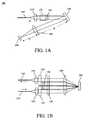
- FIG. 1 ( a )is a schematic top view of one embodiment of an optical system of the present invention that is utilized for dynamic spectral shaping.
- FIG. 1 ( b )is a schematic side view of the FIG. 1 ( a ) optical system.
- FIG. 2 ( a )is a schematic top view of a deformable grating, modulator array utilized in one embodiment of the present invention.
- FIG. 2 ( b )is a schematic side view of the FIG. 2 ( a ) deformable grating, modulator array.
- FIG. 3 ( a )is a schematic top view of a modified FIG. 1 ( a ) optical system that includes a circulator to extract the output light.
- FIG. 3 ( b )is a schematic side view of the FIG. 3 ( a ) optical system with circulator.
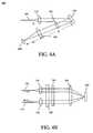
- FIG. 4 ( a )is a schematic top view of a modified FIG. 1 ( a ) optical system that includes of a quarter-wave plate to minimize PDL.
- FIG. 4 ( b )is a schematic side view of the FIG. 4 ( a ) optical system.
- FIG. 5is a schematic top view of one embodiment of an optical system of the present invention that is utilized for dynamic spectral shaping and incorporates an array waveguide grating.
- FIG. 1illustrates one embodiment of an optical system 100 of the present invention for the dynamic spectral shaping. Its comprised of an input optical fiber 105 , an output optical fiber 115 , an input collimating lens 110 of focal length f 1 , an output collimating lens 120 of focal length f 1 , a walkoff birefringent plate 130 on the input side, a walkoff birefringent plate 135 on the output side, a half wave plate 140 , a grating 150 to diffract the light onto a focusing lens 160 of focal length f 2 , and then onto the device array 200 .
- the broadband light from the input optical fiber 105is collimated by lens 110 which may be a GRIN lens, spherical lens or any other suitable lens.
- lens 110which may be a GRIN lens, spherical lens or any other suitable lens.
- the collimated lightpasses through a walkoff birefringent plate 130 such as YVO4, calcite or LiNbO3.
- the ordinary polarizationgoes straight through while the extraordinary polarization is displaced downwards by an amount, which if designed properly, should be greater than the beam size.
- the polarization of one of the displaced beamsis rotated by using a half wave plate (HWP) 140 and made the same as the other beam. Now both beams are either vertically or horizontally polarized.
- HWPhalf wave plate
- the polarization directionis chosen to maximize the diffraction efficiency of the grating 150 which may be a holographic grating or a blazed grating.
- Two parallel beamsimpinge on the grating which diffracts the light towards the upper half of a focusing lens 160 of focal length f 2 which is placed a distance f 2 away from the grating.
- This telecentric usewalks the focused beam across the device array 200 as a function of wavelength.
- the two polarization pathscome together on the device array which is segmented to cover different spectral slices.
- the reflected light from the devicegoes through the bottom half of the lens 160 and impinges on the grating which puts all the wavelengths back to gather.
- the polarizationis combined again using the HWP and the output birefringent plate 135 which is oriented opposite from the input birefringent plate.
- the beamis focused into the output fiber 115 using another collimating lens 120 .
- the device array 200may be an array of LCD elements, a suitable MEMS device array such as micro mirrors or cantilevers, an array of electro-optic modulators, an array of acousto-optic modulators or any light controlling device array.
- the preferred embodimentis based on using a deformable grating modulator array invented by Bloom et. al. (U.S. Pat. No. 5,311,360) as shown in FIGS. 2 A,B.
- the deviceis comprised of ribbons 199 of width w suspended above the substrate 198 .
- the top surface of the ribbonis a height d above the substrate. Ribbons are electrically connected and driven in pairs. Each pair controls a spectral slice.
- 201controls ⁇ 1 , 202 controls ⁇ 2 , and so on till 20 n controls ⁇ n.
- the gap between the ribbonsis also w. All ribbons and gaps are covered with a reflective layer which may be aluminum or gold.
- a reflective layerwhich may be aluminum or gold.
- dm ⁇ /2 where m is an integer.
- Now light reflected from the ribbons and the gapsis in phase and device looks like a mirror.
- the electrostatic forcestarts pulling the ribbons downwards and light starts diffracting.
- ⁇ /4all the light is diffracted out and the element is effectively off.
- Two pairs of ribbon/gapprovides enough isolation for a single-mode fiber. However more pairs can also be used.
- the shorter wavelength elementswill start out with the ribbons already slightly pulled in.
- the spectral resolution of the systemis determined by f 1 , f 2 , grating pitch and the grating incident angle. The resolution should be such that going from ⁇ 1 to ⁇ 2 moves the spot across the device array by w.
- FIGS. 3 A,BAn alternate embodiment of the optical system 300 is shown in FIGS. 3 A,B, which is the same as system 100 in FIG. 1, except a circulator 103 is used to separate out the light in the input fiber 101 from the output fiber 102 .
- FIGS. 4 A,BYet another embodiment of the optical system 400 is shown in FIGS. 4 A,B. This is again similar to system 100 shown in FIG. 1 except that polarization splitting is not employed. Since both polarizations are impinging on the grating 150 , it is desirable that the grating have high diffraction efficiency for both polarizations.
- a quarter wave plate (QWP) 140is employed to flip the vertical and horizontal polarizations on the return path. This reduces the polarization dependent loss (PDL) for the overall system assuming the device array 200 does not have any significant PDL. If PDL from the device array needs to be minimized further, the polarization independent grating modulator invention of Godil et. al. (include by cross-reference) can be used here configured as an array of elements. Another variation of this embodiment would be to use a circulator on the input side to separate out the output fiber from the input without creating a separate path.
- dispersive element 150is an arrayed waveguide grading (“AWG”).
- a suitable AWG 150is manufactured by Lightwave Microsystems, San Jose, Calif.
- device array 200which can be a controllable, deformable grating modulator, can be placed in close proximity to the dispersed output at AWG 150 . This proximity is selected to provide good coupling efficiency back into the waveguides of AWG 150 .
- the maximum distancedepends on the size of the waveguides of AWG 150 . In a preferred embodiment, the distance is 10 microns or less and can be butt-coupled.
- AWG 150disperses the light from the input optical fiber 105 and spreads the input beam in at least one dimension as a function of wavelength where it impinges on device array 200 .
- the spatially dispersed lightis reflected back into AWG 150 which subsequently recombines the light into optical fiber 105 but in a counterpropagating direction to the input.
- the output lightcan be extracted by circulator 103 .
- Other embodimentscan include a separate output port and do not require the circulator.
Landscapes
- Physics & Mathematics (AREA)
- General Physics & Mathematics (AREA)
- Optics & Photonics (AREA)
- Optical Modulation, Optical Deflection, Nonlinear Optics, Optical Demodulation, Optical Logic Elements (AREA)
Abstract
Description
Claims (15)
Priority Applications (6)
| Application Number | Priority Date | Filing Date | Title |
|---|---|---|---|
| US09/549,781US6826330B1 (en) | 1999-08-11 | 2000-04-14 | Dynamic spectral shaping for fiber-optic application |
| JP2001516015AJP2003506988A (en) | 1999-08-11 | 2000-08-08 | Dynamic spectral shaping for application to optical fibers |
| EP00979122AEP1203463A2 (en) | 1999-08-11 | 2000-08-08 | Dynamic spectral shaping in optical fibre communication |
| AU16537/01AAU1653701A (en) | 1999-08-11 | 2000-08-08 | Dynamic spectral shaping for fiber-optic application |
| PCT/US2000/021662WO2001011419A2 (en) | 1999-08-11 | 2000-08-08 | Dynamic spectral shaping in optical fibre communication |
| US09/900,753US6888983B2 (en) | 2000-04-14 | 2001-07-06 | Dynamic gain and channel equalizers |
Applications Claiming Priority (5)
| Application Number | Priority Date | Filing Date | Title |
|---|---|---|---|
| US37271299A | 1999-08-11 | 1999-08-11 | |
| US09/372,649US6169624B1 (en) | 1999-08-11 | 1999-08-11 | Achromatic optical modulators |
| US17168599P | 1999-12-21 | 1999-12-21 | |
| US09/548,788US6501600B1 (en) | 1999-08-11 | 2000-04-13 | Polarization independent grating modulator |
| US09/549,781US6826330B1 (en) | 1999-08-11 | 2000-04-14 | Dynamic spectral shaping for fiber-optic application |
Related Parent Applications (1)
| Application Number | Title | Priority Date | Filing Date |
|---|---|---|---|
| US09/548,788Continuation-In-PartUS6501600B1 (en) | 1999-08-11 | 2000-04-13 | Polarization independent grating modulator |
Related Child Applications (1)
| Application Number | Title | Priority Date | Filing Date |
|---|---|---|---|
| US09/900,753Continuation-In-PartUS6888983B2 (en) | 2000-04-14 | 2001-07-06 | Dynamic gain and channel equalizers |
Publications (1)
| Publication Number | Publication Date |
|---|---|
| US6826330B1true US6826330B1 (en) | 2004-11-30 |
Family
ID=33459063
Family Applications (1)
| Application Number | Title | Priority Date | Filing Date |
|---|---|---|---|
| US09/549,781Expired - LifetimeUS6826330B1 (en) | 1999-08-11 | 2000-04-14 | Dynamic spectral shaping for fiber-optic application |
Country Status (1)
| Country | Link |
|---|---|
| US (1) | US6826330B1 (en) |
Cited By (21)
| Publication number | Priority date | Publication date | Assignee | Title |
|---|---|---|---|---|
| US20020196496A1 (en)* | 2000-11-03 | 2002-12-26 | Network Photonics, Inc. | Reduction of polarization-dependent loss in double-pass grating configurations |
| US20050099692A1 (en)* | 2001-02-02 | 2005-05-12 | Cheetah Omni, Inc., A Texas Limited Liability Company | Variable blazed grating |
| US20060061731A1 (en)* | 2004-08-31 | 2006-03-23 | Tobias Kuhn | Systems and methods for shaping wavefronts in polychromatic light using phase shifting elements |
| US7116862B1 (en) | 2000-12-22 | 2006-10-03 | Cheetah Omni, Llc | Apparatus and method for providing gain equalization |
| US20060292828A1 (en)* | 2005-06-22 | 2006-12-28 | Advanced Semiconductor Engineering, Inc. | Wafer and method of cutting the same |
| US20070138149A1 (en)* | 2004-04-08 | 2007-06-21 | Ion Systems, Inc., A California Corporation | Multi-frequency static neutralization |
| US7339714B1 (en) | 2001-02-02 | 2008-03-04 | Cheetah Omni, Llc | Variable blazed grating based signal processing |
| US7429983B2 (en) | 2005-11-01 | 2008-09-30 | Cheetah Omni, Llc | Packet-based digital display system |
| US20090028502A1 (en)* | 2006-11-07 | 2009-01-29 | Harry Wayne Presley | Segmented prism element and associated methods for manifold fiberoptic switches |
| US7522836B2 (en) | 2001-02-02 | 2009-04-21 | Cheetah Omni, Llc | Optical logic gate based optical router |
| US20090103861A1 (en)* | 2006-11-07 | 2009-04-23 | Olympus Microsystems America, Inc. | Beam steering element and associated methods for manifold fiberoptic switches |
| US20090110349A1 (en)* | 2006-11-07 | 2009-04-30 | Olympus Microsystems America, Inc | Beam steering element and associated methods for mixed manifold fiberoptic switches |
| US20090220192A1 (en)* | 2008-02-28 | 2009-09-03 | Olympus Corporation | Wavelength selective switch with reduced chromatic dispersion and polarization-dependent loss |
| US20090231580A1 (en)* | 2006-11-07 | 2009-09-17 | Olympus Corporation | Beam steering element and associated methods for manifold fiberoptic switches and monitoring |
| US20090304328A1 (en)* | 2006-11-07 | 2009-12-10 | Olympus Microsystems America, Inc. | Beam steering element and associated methods for manifold fiberoptic switches and monitoring |
| US20100141857A1 (en)* | 2007-06-15 | 2010-06-10 | National Institute Of Information And Communications Technology | Optical waveform shaping device |
| US7769255B2 (en) | 2006-11-07 | 2010-08-03 | Olympus Corporation | High port count instantiated wavelength selective switch |
| US8937759B2 (en) | 2001-09-03 | 2015-01-20 | Thomas Swan & Co. Ltd. | Optical processing |
| EP2875393A4 (en)* | 2012-07-19 | 2016-03-16 | Finisar Corp | POLARIZATION DIVERSITY WAVE LENGTH SWITCH |
| US10257594B2 (en) | 2012-08-15 | 2019-04-09 | Thomas Swan And Co., Ltd. | Optical device and methods |
| US12334702B2 (en) | 2017-08-11 | 2025-06-17 | Molex, Llc | Optical module and erbium-doped fiber amplifier |
Citations (45)
| Publication number | Priority date | Publication date | Assignee | Title |
|---|---|---|---|---|
| US3904295A (en)* | 1972-07-31 | 1975-09-09 | Leitz Ernst Gmbh | Method and apparatus for the no-contact measurement of velocities, changes in relative position, or displacement paths |
| US4973159A (en)* | 1986-12-01 | 1990-11-27 | Hitachi, Ltd. | Spectroscope apparatus and reaction apparatus using the same |
| EP0555778A2 (en) | 1992-02-14 | 1993-08-18 | Matsushita Electric Industrial Co., Ltd. | Optical filter and optical amplifier employing said optical filters |
| US5311360A (en) | 1992-04-28 | 1994-05-10 | The Board Of Trustees Of The Leland Stanford, Junior University | Method and apparatus for modulating a light beam |
| US5414540A (en)* | 1993-06-01 | 1995-05-09 | Bell Communications Research, Inc. | Frequency-selective optical switch employing a frequency dispersive element, polarization dispersive element and polarization modulating elements |
| EP0654917A2 (en) | 1993-11-12 | 1995-05-24 | AT&T Corp. | High-density optical wavelength division multiplexing |
| US5629801A (en) | 1995-06-07 | 1997-05-13 | Silicon Light Machines | Diffraction grating light doubling collection system |
| US5661592A (en) | 1995-06-07 | 1997-08-26 | Silicon Light Machines | Method of making and an apparatus for a flat diffraction grating light valve |
| US5701005A (en)* | 1995-06-19 | 1997-12-23 | Eastman Kodak Company | Color separating diffractive optical array and image sensor |
| US5731802A (en) | 1996-04-22 | 1998-03-24 | Silicon Light Machines | Time-interleaved bit-plane, pulse-width-modulation digital display system |
| US5745271A (en) | 1996-07-31 | 1998-04-28 | Lucent Technologies, Inc. | Attenuation device for wavelength multiplexed optical fiber communications |
| US5764280A (en) | 1997-03-20 | 1998-06-09 | Silicon Light Machines Inc. | Display system including an image generator and movable scanner for same |
| US5793912A (en) | 1994-06-09 | 1998-08-11 | Apa Optics, Inc. | Tunable receiver for a wavelength division multiplexing optical apparatus and method |
| US5798743A (en) | 1995-06-07 | 1998-08-25 | Silicon Light Machines | Clear-behind matrix addressing for display systems |
| US5805759A (en) | 1996-03-27 | 1998-09-08 | Fujitsu Limited | Optical equalizer having variable transmittance versus wavelength characteristics for attenuating light |
| US5808797A (en) | 1992-04-28 | 1998-09-15 | Silicon Light Machines | Method and apparatus for modulating a light beam |
| US5841579A (en) | 1995-06-07 | 1998-11-24 | Silicon Light Machines | Flat diffraction grating light valve |
| US5847863A (en)* | 1996-04-25 | 1998-12-08 | Imra America, Inc. | Hybrid short-pulse amplifiers with phase-mismatch compensated pulse stretchers and compressors |
| WO1999038348A1 (en) | 1998-01-27 | 1999-07-29 | Tellium, Inc. | Wavelength-selective optical add/drop using tilting micro-mirrors |
| US5943158A (en) | 1998-05-05 | 1999-08-24 | Lucent Technologies Inc. | Micro-mechanical, anti-reflection, switched optical modulator array and fabrication method |
| US5946128A (en)* | 1997-08-15 | 1999-08-31 | The United States Of America As Represented By The Secretary Of Commerce | Grating assisted acousto-optic tunable filter and method |
| US5982553A (en) | 1997-03-20 | 1999-11-09 | Silicon Light Machines | Display device incorporating one-dimensional grating light-valve array |
| US5986634A (en) | 1996-12-11 | 1999-11-16 | Silicon Light Machines | Display/monitor with orientation dependent rotatable image |
| US5987200A (en)* | 1997-10-27 | 1999-11-16 | Lucent Technologies Inc. | Device for tuning wavelength response of an optical fiber grating |
| US5995281A (en)* | 1997-04-09 | 1999-11-30 | Carl Zeiss Jena Gmbh | Device for coupling the radiation of short-pulse lasers in an optical beam path of a microscope |
| US6004912A (en) | 1998-06-05 | 1999-12-21 | Silicon Light Machines | Vapor phase low molecular weight lubricants |
| US6038057A (en)* | 1998-12-18 | 2000-03-14 | Eastman Kodak Company | Method and system for actuating electro-mechanical ribbon elements in accordance to a data stream |
| US6064404A (en) | 1996-11-05 | 2000-05-16 | Silicon Light Machines | Bandwidth and frame buffer size reduction in a digital pulse-width-modulated display system |
| US6069576A (en) | 1998-04-02 | 2000-05-30 | The United States Of America As Represented By The Secretary Of The Navy | Synchro-to-digital converter |
| US6088102A (en) | 1997-10-31 | 2000-07-11 | Silicon Light Machines | Display apparatus including grating light-valve array and interferometric optical system |
| US6101036A (en) | 1998-06-23 | 2000-08-08 | Silicon Light Machines | Embossed diffraction grating alone and in combination with changeable image display |
| US6130770A (en) | 1998-06-23 | 2000-10-10 | Silicon Light Machines | Electron gun activated grating light valve |
| US6141361A (en)* | 1994-09-30 | 2000-10-31 | British Technology Group Limited | Wavelength selective filter |
| US6147341A (en)* | 1998-02-13 | 2000-11-14 | Lucent Technologies Inc. | Temperature compensating device for fiber gratings |
| US6178284B1 (en) | 1998-09-30 | 2001-01-23 | Lucent Technologies, Inc. | Variable single-mode attenuators by spatial interference |
| US6215579B1 (en) | 1998-06-24 | 2001-04-10 | Silicon Light Machines | Method and apparatus for modulating an incident light beam for forming a two-dimensional image |
| US6268952B1 (en)* | 1998-07-14 | 2001-07-31 | Lightconnect, Inc. | Micromechanical light steering optical switch |
| US6268948B1 (en)* | 1999-06-11 | 2001-07-31 | Creo Products Inc. | Micromachined reflective light valve |
| US6271808B1 (en) | 1998-06-05 | 2001-08-07 | Silicon Light Machines | Stereo head mounted display using a single display device |
| US6275623B1 (en)* | 1999-07-12 | 2001-08-14 | Corning Incorporated | Dynamically configurable spectral filter |
| US6285500B1 (en)* | 1999-06-29 | 2001-09-04 | Corning Incorporated | Wavelength selective switch |
| US6327398B1 (en)* | 1997-02-13 | 2001-12-04 | The Regents Of The University Of California | Multi-wavelength cross-connect optical switch |
| US6342966B1 (en)* | 1996-11-06 | 2002-01-29 | Corning Incorporated | Crosstalk suppression in a multipath optical amplifier |
| US6357913B1 (en)* | 1998-02-12 | 2002-03-19 | Novera Optics, Inc. | Add/drop acousto-optic filter |
| US6453095B2 (en)* | 1997-12-15 | 2002-09-17 | University Of Southern California | Tuning of optical dispersion by using a tunable fiber bragg grating |
- 2000
- 2000-04-14USUS09/549,781patent/US6826330B1/ennot_activeExpired - Lifetime
Patent Citations (47)
| Publication number | Priority date | Publication date | Assignee | Title |
|---|---|---|---|---|
| US3904295A (en)* | 1972-07-31 | 1975-09-09 | Leitz Ernst Gmbh | Method and apparatus for the no-contact measurement of velocities, changes in relative position, or displacement paths |
| US4973159A (en)* | 1986-12-01 | 1990-11-27 | Hitachi, Ltd. | Spectroscope apparatus and reaction apparatus using the same |
| EP0555778A2 (en) | 1992-02-14 | 1993-08-18 | Matsushita Electric Industrial Co., Ltd. | Optical filter and optical amplifier employing said optical filters |
| US5311360A (en) | 1992-04-28 | 1994-05-10 | The Board Of Trustees Of The Leland Stanford, Junior University | Method and apparatus for modulating a light beam |
| US5808797A (en) | 1992-04-28 | 1998-09-15 | Silicon Light Machines | Method and apparatus for modulating a light beam |
| US5414540A (en)* | 1993-06-01 | 1995-05-09 | Bell Communications Research, Inc. | Frequency-selective optical switch employing a frequency dispersive element, polarization dispersive element and polarization modulating elements |
| EP0654917A2 (en) | 1993-11-12 | 1995-05-24 | AT&T Corp. | High-density optical wavelength division multiplexing |
| US5526155A (en)* | 1993-11-12 | 1996-06-11 | At&T Corp. | High-density optical wavelength division multiplexing |
| US5793912A (en) | 1994-06-09 | 1998-08-11 | Apa Optics, Inc. | Tunable receiver for a wavelength division multiplexing optical apparatus and method |
| US6141361A (en)* | 1994-09-30 | 2000-10-31 | British Technology Group Limited | Wavelength selective filter |
| US5661592A (en) | 1995-06-07 | 1997-08-26 | Silicon Light Machines | Method of making and an apparatus for a flat diffraction grating light valve |
| US5798743A (en) | 1995-06-07 | 1998-08-25 | Silicon Light Machines | Clear-behind matrix addressing for display systems |
| US5629801A (en) | 1995-06-07 | 1997-05-13 | Silicon Light Machines | Diffraction grating light doubling collection system |
| US5841579A (en) | 1995-06-07 | 1998-11-24 | Silicon Light Machines | Flat diffraction grating light valve |
| US5701005A (en)* | 1995-06-19 | 1997-12-23 | Eastman Kodak Company | Color separating diffractive optical array and image sensor |
| US5805759A (en) | 1996-03-27 | 1998-09-08 | Fujitsu Limited | Optical equalizer having variable transmittance versus wavelength characteristics for attenuating light |
| US5731802A (en) | 1996-04-22 | 1998-03-24 | Silicon Light Machines | Time-interleaved bit-plane, pulse-width-modulation digital display system |
| US5847863A (en)* | 1996-04-25 | 1998-12-08 | Imra America, Inc. | Hybrid short-pulse amplifiers with phase-mismatch compensated pulse stretchers and compressors |
| US5745271A (en) | 1996-07-31 | 1998-04-28 | Lucent Technologies, Inc. | Attenuation device for wavelength multiplexed optical fiber communications |
| US6064404A (en) | 1996-11-05 | 2000-05-16 | Silicon Light Machines | Bandwidth and frame buffer size reduction in a digital pulse-width-modulated display system |
| US6342966B1 (en)* | 1996-11-06 | 2002-01-29 | Corning Incorporated | Crosstalk suppression in a multipath optical amplifier |
| US5986634A (en) | 1996-12-11 | 1999-11-16 | Silicon Light Machines | Display/monitor with orientation dependent rotatable image |
| US6327398B1 (en)* | 1997-02-13 | 2001-12-04 | The Regents Of The University Of California | Multi-wavelength cross-connect optical switch |
| US5764280A (en) | 1997-03-20 | 1998-06-09 | Silicon Light Machines Inc. | Display system including an image generator and movable scanner for same |
| US5982553A (en) | 1997-03-20 | 1999-11-09 | Silicon Light Machines | Display device incorporating one-dimensional grating light-valve array |
| US5995281A (en)* | 1997-04-09 | 1999-11-30 | Carl Zeiss Jena Gmbh | Device for coupling the radiation of short-pulse lasers in an optical beam path of a microscope |
| US5946128A (en)* | 1997-08-15 | 1999-08-31 | The United States Of America As Represented By The Secretary Of Commerce | Grating assisted acousto-optic tunable filter and method |
| US5987200A (en)* | 1997-10-27 | 1999-11-16 | Lucent Technologies Inc. | Device for tuning wavelength response of an optical fiber grating |
| US6088102A (en) | 1997-10-31 | 2000-07-11 | Silicon Light Machines | Display apparatus including grating light-valve array and interferometric optical system |
| US6453095B2 (en)* | 1997-12-15 | 2002-09-17 | University Of Southern California | Tuning of optical dispersion by using a tunable fiber bragg grating |
| WO1999038348A1 (en) | 1998-01-27 | 1999-07-29 | Tellium, Inc. | Wavelength-selective optical add/drop using tilting micro-mirrors |
| US6357913B1 (en)* | 1998-02-12 | 2002-03-19 | Novera Optics, Inc. | Add/drop acousto-optic filter |
| US6147341A (en)* | 1998-02-13 | 2000-11-14 | Lucent Technologies Inc. | Temperature compensating device for fiber gratings |
| US6069576A (en) | 1998-04-02 | 2000-05-30 | The United States Of America As Represented By The Secretary Of The Navy | Synchro-to-digital converter |
| US5943158A (en) | 1998-05-05 | 1999-08-24 | Lucent Technologies Inc. | Micro-mechanical, anti-reflection, switched optical modulator array and fabrication method |
| US6004912A (en) | 1998-06-05 | 1999-12-21 | Silicon Light Machines | Vapor phase low molecular weight lubricants |
| US6251842B1 (en) | 1998-06-05 | 2001-06-26 | Silicon Light Machines | Vapor phase low molecular weight lubricants |
| US6271808B1 (en) | 1998-06-05 | 2001-08-07 | Silicon Light Machines | Stereo head mounted display using a single display device |
| US6130770A (en) | 1998-06-23 | 2000-10-10 | Silicon Light Machines | Electron gun activated grating light valve |
| US6101036A (en) | 1998-06-23 | 2000-08-08 | Silicon Light Machines | Embossed diffraction grating alone and in combination with changeable image display |
| US6215579B1 (en) | 1998-06-24 | 2001-04-10 | Silicon Light Machines | Method and apparatus for modulating an incident light beam for forming a two-dimensional image |
| US6268952B1 (en)* | 1998-07-14 | 2001-07-31 | Lightconnect, Inc. | Micromechanical light steering optical switch |
| US6178284B1 (en) | 1998-09-30 | 2001-01-23 | Lucent Technologies, Inc. | Variable single-mode attenuators by spatial interference |
| US6038057A (en)* | 1998-12-18 | 2000-03-14 | Eastman Kodak Company | Method and system for actuating electro-mechanical ribbon elements in accordance to a data stream |
| US6268948B1 (en)* | 1999-06-11 | 2001-07-31 | Creo Products Inc. | Micromachined reflective light valve |
| US6285500B1 (en)* | 1999-06-29 | 2001-09-04 | Corning Incorporated | Wavelength selective switch |
| US6275623B1 (en)* | 1999-07-12 | 2001-08-14 | Corning Incorporated | Dynamically configurable spectral filter |
Non-Patent Citations (3)
| Title |
|---|
| Ford, Joseph E. and Walker, James A. "Dynamic Spectral Power Equalization Using Micro-Opto-Mechanics", IEEE Photonics Technology Letters, vol. 10, No. 10, Oct. 1998. |
| Parker, Michael C. "Dynamic Digital Holographic Wavelength Filtering", Journal of Lightwave Technology, vol. 16, No. 7, Jul. 1998. |
| Wang, Lei and Weiner, A.M. "Programmable Spectral Phase Coding of an Amplified Spontaneous Emission Light Source", Optics Communications, 167 (1999) 211-224, Aug. 15, 1999. |
Cited By (40)
| Publication number | Priority date | Publication date | Assignee | Title |
|---|---|---|---|---|
| US8457501B2 (en)* | 2000-11-03 | 2013-06-04 | Altera Corporation | Reduction of polarization-dependent loss in double-pass grating configurations |
| US20020196496A1 (en)* | 2000-11-03 | 2002-12-26 | Network Photonics, Inc. | Reduction of polarization-dependent loss in double-pass grating configurations |
| US7116862B1 (en) | 2000-12-22 | 2006-10-03 | Cheetah Omni, Llc | Apparatus and method for providing gain equalization |
| US7339714B1 (en) | 2001-02-02 | 2008-03-04 | Cheetah Omni, Llc | Variable blazed grating based signal processing |
| US20050099692A1 (en)* | 2001-02-02 | 2005-05-12 | Cheetah Omni, Inc., A Texas Limited Liability Company | Variable blazed grating |
| US6972886B2 (en)* | 2001-02-02 | 2005-12-06 | Cheetah Omni, Llc | Variable blazed grating |
| US7522836B2 (en) | 2001-02-02 | 2009-04-21 | Cheetah Omni, Llc | Optical logic gate based optical router |
| US11073739B2 (en) | 2001-09-03 | 2021-07-27 | Thomas Swan & Co. Ltd. | Optical processing |
| US10642126B2 (en) | 2001-09-03 | 2020-05-05 | Thomas Swan & Co. Ltd. | Optical processing |
| US10180616B2 (en) | 2001-09-03 | 2019-01-15 | Thomas Swan & Co. Ltd. | Optical processing |
| US9529325B2 (en) | 2001-09-03 | 2016-12-27 | Thomas Swan & Co. Ltd | Optical processing |
| US8937759B2 (en) | 2001-09-03 | 2015-01-20 | Thomas Swan & Co. Ltd. | Optical processing |
| US20070138149A1 (en)* | 2004-04-08 | 2007-06-21 | Ion Systems, Inc., A California Corporation | Multi-frequency static neutralization |
| US7360893B2 (en)* | 2004-08-31 | 2008-04-22 | 20/10 Perfect Vision Optische Geraete Gmbh | Systems and methods for shaping wavefronts in polychromatic light using phase shifting elements |
| US20060061731A1 (en)* | 2004-08-31 | 2006-03-23 | Tobias Kuhn | Systems and methods for shaping wavefronts in polychromatic light using phase shifting elements |
| US20060292828A1 (en)* | 2005-06-22 | 2006-12-28 | Advanced Semiconductor Engineering, Inc. | Wafer and method of cutting the same |
| US7429983B2 (en) | 2005-11-01 | 2008-09-30 | Cheetah Omni, Llc | Packet-based digital display system |
| US8379061B2 (en) | 2005-11-01 | 2013-02-19 | Gopala Solutions Limited Liability Company | Packet-based digital display system |
| US20090028502A1 (en)* | 2006-11-07 | 2009-01-29 | Harry Wayne Presley | Segmented prism element and associated methods for manifold fiberoptic switches |
| US7720329B2 (en) | 2006-11-07 | 2010-05-18 | Olympus Corporation | Segmented prism element and associated methods for manifold fiberoptic switches |
| US20090103861A1 (en)* | 2006-11-07 | 2009-04-23 | Olympus Microsystems America, Inc. | Beam steering element and associated methods for manifold fiberoptic switches |
| US7769255B2 (en) | 2006-11-07 | 2010-08-03 | Olympus Corporation | High port count instantiated wavelength selective switch |
| US7873246B2 (en) | 2006-11-07 | 2011-01-18 | Olympus Corporation | Beam steering element and associated methods for manifold fiberoptic switches and monitoring |
| US8000568B2 (en) | 2006-11-07 | 2011-08-16 | Olympus Corporation | Beam steering element and associated methods for mixed manifold fiberoptic switches |
| US8131123B2 (en) | 2006-11-07 | 2012-03-06 | Olympus Corporation | Beam steering element and associated methods for manifold fiberoptic switches and monitoring |
| US20090110349A1 (en)* | 2006-11-07 | 2009-04-30 | Olympus Microsystems America, Inc | Beam steering element and associated methods for mixed manifold fiberoptic switches |
| US20090231580A1 (en)* | 2006-11-07 | 2009-09-17 | Olympus Corporation | Beam steering element and associated methods for manifold fiberoptic switches and monitoring |
| US7702194B2 (en) | 2006-11-07 | 2010-04-20 | Olympus Corporation | Beam steering element and associated methods for manifold fiberoptic switches |
| US20090304328A1 (en)* | 2006-11-07 | 2009-12-10 | Olympus Microsystems America, Inc. | Beam steering element and associated methods for manifold fiberoptic switches and monitoring |
| US8571418B2 (en) | 2007-06-15 | 2013-10-29 | National Institute Of Information And Communications Technology | High resolution optical waveform shaping device having phase shift compensation associated with optical intensity modulation |
| EP2169448A4 (en)* | 2007-06-15 | 2012-05-30 | Nat Inst Inf & Comm Tech | OPTICAL WAVEFORM SHAPING DEVICE |
| US20100141857A1 (en)* | 2007-06-15 | 2010-06-10 | National Institute Of Information And Communications Technology | Optical waveform shaping device |
| US20090220233A1 (en)* | 2008-02-28 | 2009-09-03 | Olympus Corporation | Wavelength selective switch having distinct planes of operation |
| US20090220192A1 (en)* | 2008-02-28 | 2009-09-03 | Olympus Corporation | Wavelength selective switch with reduced chromatic dispersion and polarization-dependent loss |
| US8190025B2 (en) | 2008-02-28 | 2012-05-29 | Olympus Corporation | Wavelength selective switch having distinct planes of operation |
| EP2875393A4 (en)* | 2012-07-19 | 2016-03-16 | Finisar Corp | POLARIZATION DIVERSITY WAVE LENGTH SWITCH |
| US9654848B2 (en) | 2012-07-19 | 2017-05-16 | Finisar Corporation | Polarization diverse wavelength selective switch |
| US10461878B2 (en) | 2012-07-19 | 2019-10-29 | Finisar Corporation | Polarization diverse wavelength selective switch |
| US10257594B2 (en) | 2012-08-15 | 2019-04-09 | Thomas Swan And Co., Ltd. | Optical device and methods |
| US12334702B2 (en) | 2017-08-11 | 2025-06-17 | Molex, Llc | Optical module and erbium-doped fiber amplifier |
Similar Documents
| Publication | Publication Date | Title |
|---|---|---|
| US6826330B1 (en) | Dynamic spectral shaping for fiber-optic application | |
| US7013064B2 (en) | Freespace tunable optoelectronic device and method | |
| Ford et al. | Wavelength add-drop switching using tilting micromirrors | |
| EP1203463A2 (en) | Dynamic spectral shaping in optical fibre communication | |
| EP1292857B1 (en) | Dynamically variable diffractive optical devices | |
| US6678445B2 (en) | Dynamic gain flattening filter | |
| US7019883B2 (en) | Dynamic optical filter having a spatial light modulator | |
| US5579420A (en) | Optical filter | |
| US6239891B1 (en) | Optical demultiplexer and method of assembling same | |
| US7634165B2 (en) | Monolithic tunable lasers and reflectors | |
| US7126250B2 (en) | Apparatus comprising an array of tightly spaced rotatable optical elements with two axes of rotation | |
| JPH10300976A (en) | Optical fiber wavelength multiplexer and demultiplexer | |
| EP1386193A2 (en) | Variable optical source | |
| US6983090B2 (en) | High resolution tunable optical filter | |
| US6937627B2 (en) | Stable and high speed full range laser wavelength tuning with reduced group delay and temperature variation compensation | |
| US6496622B1 (en) | Diffractive structure for high-dispersion WDM applications | |
| JP2005525604A (en) | Method and device for variable optical attenuator | |
| JP2004500589A (en) | Polarization independent grating modulator | |
| JP4409320B2 (en) | Variable optical gain equalizer and optical gain equalizer | |
| US7286764B1 (en) | Reconfigurable modulator-based optical add-and-drop multiplexer | |
| US6888983B2 (en) | Dynamic gain and channel equalizers | |
| JP3460960B2 (en) | Broadband spatial light phase modulator | |
| Neukermans | MEMS devices for all optical networks | |
| Yaqoob et al. | Low-loss wavelength-multiplexed optical scanners using volume Bragg gratings for transmit-receive lasercom systems | |
| US20030206701A1 (en) | Polarization independent grating modulator |
Legal Events
| Date | Code | Title | Description |
|---|---|---|---|
| AS | Assignment | Owner name:LIGHTCONNECT, CALIFORNIA Free format text:ASSIGNMENT OF ASSIGNORS INTEREST;ASSIGNOR:GODIL, ASIF;REEL/FRAME:010997/0580 Effective date:20000607 | |
| AS | Assignment | Owner name:LIGHTCONNECT, INC., CALIFORNIA Free format text:ASSIGNMENT OF ASSIGNORS INTEREST;ASSIGNORS:GODIL, ASIF A.;BLOOM, DAVID M.;REEL/FRAME:011399/0466 Effective date:20001211 | |
| STCF | Information on status: patent grant | Free format text:PATENTED CASE | |
| FEPP | Fee payment procedure | Free format text:PAYOR NUMBER ASSIGNED (ORIGINAL EVENT CODE: ASPN); ENTITY STATUS OF PATENT OWNER: LARGE ENTITY | |
| FEPP | Fee payment procedure | Free format text:PAT HOLDER NO LONGER CLAIMS SMALL ENTITY STATUS, ENTITY STATUS SET TO UNDISCOUNTED (ORIGINAL EVENT CODE: STOL); ENTITY STATUS OF PATENT OWNER: LARGE ENTITY | |
| FPAY | Fee payment | Year of fee payment:4 | |
| AS | Assignment | Owner name:NEOPHOTONICS CORPORATION,CALIFORNIA Free format text:ASSIGNMENT OF ASSIGNORS INTEREST;ASSIGNOR:LIGHTCONNECT, INC.;REEL/FRAME:024066/0420 Effective date:20100311 | |
| FPAY | Fee payment | Year of fee payment:8 | |
| FPAY | Fee payment | Year of fee payment:12 |