US6824915B1 - Air managing systems and methods for gas depolarized power supplies utilizing a diaphragm - Google Patents
Air managing systems and methods for gas depolarized power supplies utilizing a diaphragmDownload PDFInfo
- Publication number
- US6824915B1 US6824915B1US09/602,187US60218700AUS6824915B1US 6824915 B1US6824915 B1US 6824915B1US 60218700 AUS60218700 AUS 60218700AUS 6824915 B1US6824915 B1US 6824915B1
- Authority
- US
- United States
- Prior art keywords
- diaphragm
- air
- coil
- resilient
- current
- Prior art date
- Legal status (The legal status is an assumption and is not a legal conclusion. Google has not performed a legal analysis and makes no representation as to the accuracy of the status listed.)
- Expired - Lifetime, expires
Links
- 238000000034methodMethods0.000titleclaimsdescription16
- 239000000446fuelSubstances0.000claimsabstractdescription12
- 230000005294ferromagnetic effectEffects0.000claimsdescription72
- 239000000463materialSubstances0.000claimsdescription20
- 230000005291magnetic effectEffects0.000claimsdescription14
- 230000010355oscillationEffects0.000claimsdescription8
- 239000003302ferromagnetic materialSubstances0.000claimsdescription7
- 239000003570airSubstances0.000description261
- 210000004027cellAnatomy0.000description101
- 238000009423ventilationMethods0.000description42
- 238000005096rolling processMethods0.000description40
- 238000002955isolationMethods0.000description25
- 238000009792diffusion processMethods0.000description24
- 239000007789gasSubstances0.000description20
- 230000001413cellular effectEffects0.000description18
- 239000012080ambient airSubstances0.000description14
- QVGXLLKOCUKJST-UHFFFAOYSA-Natomic oxygenChemical compound[O]QVGXLLKOCUKJST-UHFFFAOYSA-N0.000description11
- 239000001301oxygenSubstances0.000description11
- 229910052760oxygenInorganic materials0.000description11
- OKKJLVBELUTLKV-UHFFFAOYSA-NMethanolChemical compoundOCOKKJLVBELUTLKV-UHFFFAOYSA-N0.000description9
- 230000009977dual effectEffects0.000description9
- 229920001746electroactive polymerPolymers0.000description8
- 230000005672electromagnetic fieldEffects0.000description8
- 230000008901benefitEffects0.000description7
- XLYOFNOQVPJJNP-UHFFFAOYSA-NwaterSubstancesOXLYOFNOQVPJJNP-UHFFFAOYSA-N0.000description7
- 230000000977initiatory effectEffects0.000description5
- 229910052751metalInorganic materials0.000description5
- 239000002184metalSubstances0.000description5
- 230000007704transitionEffects0.000description4
- UFHFLCQGNIYNRP-UHFFFAOYSA-NHydrogenChemical compound[H][H]UFHFLCQGNIYNRP-UHFFFAOYSA-N0.000description3
- 239000010405anode materialSubstances0.000description3
- 230000001419dependent effectEffects0.000description3
- 230000006870functionEffects0.000description3
- 239000001257hydrogenSubstances0.000description3
- 229910052739hydrogenInorganic materials0.000description3
- 239000012212insulatorSubstances0.000description3
- 239000004033plasticSubstances0.000description3
- 230000008569processEffects0.000description3
- 229920002725thermoplastic elastomerPolymers0.000description3
- HCHKCACWOHOZIP-UHFFFAOYSA-NZincChemical compound[Zn]HCHKCACWOHOZIP-UHFFFAOYSA-N0.000description2
- 238000005452bendingMethods0.000description2
- 230000008859changeEffects0.000description2
- 230000001010compromised effectEffects0.000description2
- 238000001514detection methodMethods0.000description2
- 238000010586diagramMethods0.000description2
- 238000001035dryingMethods0.000description2
- 238000003487electrochemical reactionMethods0.000description2
- 239000003792electrolyteSubstances0.000description2
- -1hydroxide ionsChemical class0.000description2
- 229920000554ionomerPolymers0.000description2
- 239000007788liquidSubstances0.000description2
- 238000004519manufacturing processMethods0.000description2
- 239000000376reactantSubstances0.000description2
- 230000004044responseEffects0.000description2
- 229910052725zincInorganic materials0.000description2
- 239000011701zincSubstances0.000description2
- 229920000557Nafion®Polymers0.000description1
- 230000003213activating effectEffects0.000description1
- 230000004913activationEffects0.000description1
- 210000003850cellular structureAnatomy0.000description1
- 229920001971elastomerPolymers0.000description1
- 239000000806elastomerSubstances0.000description1
- 239000008151electrolyte solutionSubstances0.000description1
- 229940021013electrolyte solutionDrugs0.000description1
- 230000007613environmental effectEffects0.000description1
- 230000036571hydrationEffects0.000description1
- 238000006703hydration reactionMethods0.000description1
- 239000003014ion exchange membraneSubstances0.000description1
- 230000013011matingEffects0.000description1
- 230000007246mechanismEffects0.000description1
- 239000012528membraneSubstances0.000description1
- 239000000203mixtureSubstances0.000description1
- 230000004048modificationEffects0.000description1
- 238000012986modificationMethods0.000description1
- 238000012544monitoring processMethods0.000description1
- 230000002093peripheral effectEffects0.000description1
- 150000003057platinumChemical class0.000description1
- 229920000642polymerPolymers0.000description1
- 239000005518polymer electrolyteSubstances0.000description1
- 230000002028prematureEffects0.000description1
- 239000012858resilient materialSubstances0.000description1
- 229920003031santoprenePolymers0.000description1
- 239000007787solidSubstances0.000description1
Images


Classifications
- H—ELECTRICITY
- H01—ELECTRIC ELEMENTS
- H01M—PROCESSES OR MEANS, e.g. BATTERIES, FOR THE DIRECT CONVERSION OF CHEMICAL ENERGY INTO ELECTRICAL ENERGY
- H01M8/00—Fuel cells; Manufacture thereof
- H01M8/04—Auxiliary arrangements, e.g. for control of pressure or for circulation of fluids
- H01M8/04298—Processes for controlling fuel cells or fuel cell systems
- H01M8/04694—Processes for controlling fuel cells or fuel cell systems characterised by variables to be controlled
- H01M8/04746—Pressure; Flow
- H01M8/04753—Pressure; Flow of fuel cell reactants
- H—ELECTRICITY
- H01—ELECTRIC ELEMENTS
- H01M—PROCESSES OR MEANS, e.g. BATTERIES, FOR THE DIRECT CONVERSION OF CHEMICAL ENERGY INTO ELECTRICAL ENERGY
- H01M12/00—Hybrid cells; Manufacture thereof
- H01M12/04—Hybrid cells; Manufacture thereof composed of a half-cell of the fuel-cell type and of a half-cell of the primary-cell type
- H01M12/06—Hybrid cells; Manufacture thereof composed of a half-cell of the fuel-cell type and of a half-cell of the primary-cell type with one metallic and one gaseous electrode
- H—ELECTRICITY
- H01—ELECTRIC ELEMENTS
- H01M—PROCESSES OR MEANS, e.g. BATTERIES, FOR THE DIRECT CONVERSION OF CHEMICAL ENERGY INTO ELECTRICAL ENERGY
- H01M6/00—Primary cells; Manufacture thereof
- H01M6/50—Methods or arrangements for servicing or maintenance, e.g. for maintaining operating temperature
- H—ELECTRICITY
- H01—ELECTRIC ELEMENTS
- H01M—PROCESSES OR MEANS, e.g. BATTERIES, FOR THE DIRECT CONVERSION OF CHEMICAL ENERGY INTO ELECTRICAL ENERGY
- H01M8/00—Fuel cells; Manufacture thereof
- H01M8/04—Auxiliary arrangements, e.g. for control of pressure or for circulation of fluids
- H01M8/04082—Arrangements for control of reactant parameters, e.g. pressure or concentration
- H01M8/04089—Arrangements for control of reactant parameters, e.g. pressure or concentration of gaseous reactants
- H—ELECTRICITY
- H01—ELECTRIC ELEMENTS
- H01M—PROCESSES OR MEANS, e.g. BATTERIES, FOR THE DIRECT CONVERSION OF CHEMICAL ENERGY INTO ELECTRICAL ENERGY
- H01M8/00—Fuel cells; Manufacture thereof
- H01M8/04—Auxiliary arrangements, e.g. for control of pressure or for circulation of fluids
- H01M8/04298—Processes for controlling fuel cells or fuel cell systems
- H01M8/04694—Processes for controlling fuel cells or fuel cell systems characterised by variables to be controlled
- H01M8/04746—Pressure; Flow
- H01M8/04783—Pressure differences, e.g. between anode and cathode
- Y—GENERAL TAGGING OF NEW TECHNOLOGICAL DEVELOPMENTS; GENERAL TAGGING OF CROSS-SECTIONAL TECHNOLOGIES SPANNING OVER SEVERAL SECTIONS OF THE IPC; TECHNICAL SUBJECTS COVERED BY FORMER USPC CROSS-REFERENCE ART COLLECTIONS [XRACs] AND DIGESTS
- Y02—TECHNOLOGIES OR APPLICATIONS FOR MITIGATION OR ADAPTATION AGAINST CLIMATE CHANGE
- Y02E—REDUCTION OF GREENHOUSE GAS [GHG] EMISSIONS, RELATED TO ENERGY GENERATION, TRANSMISSION OR DISTRIBUTION
- Y02E60/00—Enabling technologies; Technologies with a potential or indirect contribution to GHG emissions mitigation
- Y02E60/30—Hydrogen technology
- Y02E60/50—Fuel cells
Definitions
- the present inventionrelates to gas depolarized electrochemical power sources, such as metal-air batteries or fuel cells of the type that are supplied with reactive gas by an active air moving device, and more particularly relates to an air mover mechanism that utilizes a diaphragm or bellows to move air in and out of one or more air openings or to move air from an inlet to an outlet.
- a metal-air cellsuch as a zinc-air cell
- oxygen from the ambient airis converted at the one or more cathodes to produce hydroxide ions.
- the metallic zinc anodeis then oxidized by the hydroxide ions. Water and electrons are released in this electrochemical reaction to provide electrical power.
- metal-air cellsfound limited commercial use in devices, such as hearing aids, which required a low level of power.
- the air openings which admitted air to the air cathodewere so small that the cells could operate for some time without flooding or drying out as a result of the typical difference between the outside relative humidity and the water vapor pressure within the cell.
- the power output of such cellswas too low to operate devices such as camcorders, cellular phones, or laptop computers.
- enlarging the air openings of a typical “button cell”was not practical because it would lead to premature failure as a result of flooding or drying out.
- metal-air cells containing air managersprovide relatively high power output and long lifetime with relatively low weight. These advantages are due in part to the fact that metal-air cells utilize oxygen from the ambient air as the reactant in the electrochemical process as opposed to a heavier material such as a metal or a metallic composition. Examples of air managers are shown in U.S. Pat. Nos. 4,913,983, 5,356,729, 5,691,074 and 5,919,582.
- a disadvantage of most air managersis that they utilize an air moving device, typically a fan or an air pump, that occupies space that could otherwise be used for battery chemistry to prolong the life of the battery. This loss of space presents a particular challenge in attempts to provide a practical metal-air cell in small enclosures such as the “AA” cylindrical size now used as a standard in many electronic devices.
- air moving devices used in metal-air batteriesalso consume energy stored in the metal-air cells that might otherwise be delivered as power output to a load. Complicated electronics for controlling an air manager can increase this use of stored energy; in addition they add considerable expense. Also, as most air moving devices used in metal-air cells distribute air to a cathode plenum at low pressure, a flow path must be defined passing over all regions of the cathode surface to evenly distribute air to the entire cathode surface. Thus, the function of bringing in make up air and the function of mixing and distributing air within the battery have been separate. A further disadvantage of fans used as air moving devices in metal-air cells is that they may create noise at a level disruptive to users of devices such as cellular telephones.
- metal-air cellsare their high energy density resulting from the low weight of the air electrode, this advantage has been compromised by the cost, space and power required for an effective air manager, and the noise it may produce. In addition, the operation of the air manager may not be necessary for all levels of power draw from the metal-air cell.
- an air manager incorporating an air moving devicethat occupies less of the volume available for battery chemistry, is usable with advanced systems for isolating the air electrodes when power is not being drawn from the metal-air cell, is quiet, needs relatively simple controls, consumes power at a relatively low rate, and provides similar advantages for fuel cells.
- a control means for the air managerthat operates the air manager when necessary during high current draw modes and causes the air manager not to operate during low current draw modes.
- the present inventionseeks to provide an improved gas moving device for gas depolarized cells that occupies a minimal amount of the volume available for other cell components, is usable with advanced systems for isolating the air electrodes when power is not being drawn from the cell, requires either simple or no control logic circuitry, is quiet, and consumes power at a relatively low rate.
- this objectis accomplished by placing the cell or battery of cells in a casing with at least one ventilation passageway extending from the gas electrodes to an outside gas supply.
- a resilient diaphragmis placed within the casing and caused to reciprocate, moving in one direction by an electrically induced force an electromagnetic field and in the opposite direction by the resiliency of the diaphragm. The movement of the diaphragm causes gas to be exchanged between the interior of the casing adjacent to the gas electrode and exterior of the casing through the ventilation passageway.
- the present inventionprovides a resilient ferromagnetic diaphragm having two sides.
- a coilis positioned near the diaphragm in order to attract the resilient ferromagnetic diaphragm when an electromagnetic field is created by an electrical current passing through the coil.
- the resilient ferromagnetic diaphragmmay be constructed of a resilient diaphragm with a ferromagnetic plate attached to one side or may be formed from a resilient ferromagnetic material.
- the present inventionprovides a resilient ferromagnetic diaphragm with two sides and a coil positioned near the diaphragm.
- An electrical circuit with an electrical current sourceis used to direct an electrical current through the coil.
- the current through the coilcreates an electromagnetic magnetic field which attracts the diaphragm and causes it to move when a predetermined level of electrical current passes through the coil.
- the electrical circuitalso contains a pair of contacts with one of the contacts connected to the diaphragm.
- the contactsare closed when the current flow through the coil is less than a predetermined level. However, when the current flow through the coil is greater than a predetermined level, the diaphragm moves. As the diaphragm moves, the contacts are opened, thus breaking the circuit, de-energizing the coil, and allowing the resiliency of the diaphragm to return it to the original position and remaking the circuit.
- the de-energizing and re-energizing of the coilmay be repeated to cause the diaphragm to oscillate.
- the resilient ferromagnetic diaphragmmay be constructed of a resilient diaphragm with a ferromagnetic plate attached to one side or may be formed from a resilient ferromagnetic material.
- the present inventionprovides an electrically activated diaphragm with two sides.
- An electrical circuit with an electrical current sourceis used to direct an electrical current through the electrically activated diaphragm.
- the current through the electrically activated diaphragmcauses the diaphragm to deform when a predetermined level of electrical current passes through it.
- the electrical circuitalso contains a pair of contacts with one of the contacts connected to the diaphragm.
- the contactsare closed when the current flow through the electrically activated diaphragm is less than a predetermined level. However, when the current flow through the electrically activated diaphragm is greater than a predetermined level, the diaphragm deforms. As the diaphragm deforms, the contacts are opened, thus breaking the circuit, and allowing the diaphragm to return it to the original position and remaking the circuit.
- the de-energizing and re-energizing of the diaphragmmay be repeated to cause the diaphragm to oscillate.
- the electrically activated diaphragmmay be constructed of a piezoelectric or EAPS material, or a resilient diaphragm with a strip of piezoelectric material attached to one side.
- Another aspect of the inventionis a method for moving air in gas depolarized cell or battery of cells by encasing the cell or battery of cells in a body having at least one ventilation passageway and reciprocating a resilient diaphragm contained in the body in one direction with an electromagnetic field and in the other direction by the resiliency of the diaphragm.
- the gas depolarized cellmay be either a metal-air cell or a fuel cell of the type that provide a gaseous or liquid fuel, such as hydrogen or methanol.
- the resilient diaphragmis manipulated by positioning a coil near the diaphragm and moving the diaphragm when an electromagnetic field is created by an electrical current passing through the coil. When the electrical current through the coil is switched off, the diaphragm returns to its original position due to the resiliency of the diaphragm.
- the manipulation of the diaphragmis controlled by positioning a coil in proximity to the resilient ferromagnetic diaphragm; providing an electrical circuit having an electrical current source; and directing electrical current from the electrical current source through the coil to create an electromagnetic magnetic field to attract the diaphragm and cause it to move when a predetermined level of electrical current passes through the coil.
- the diaphragmis manipulated by providing a pair of contacts with one of the contacts connected to the diaphragm and closed when current flow through the coil is less than a predetermined level; and moving the diaphragm when the presence of current flow through the coil is greater than a predetermined level. When the diaphragm moves, the contacts open thus breaking the circuit, de-energizing the coil, and allowing the resiliency of the diaphragm to return it to the original position.
- the electrical circuitmay be reestablished when the contacts are closed after the diaphragm has returned to its original position. When this is done, the electromagnetic magnetic field is recreated and attracts the diaphragm, thus causing the oscillation of the diaphragm while the electrical current available to the coil is greater than a predetermined level.
- Another aspect of the inventionis an gas mover system for an gas depolarized power supply associated with a load having at least two modes of operation drawing different levels of current from the power supply.
- a casing having at least one ventilation passagewayis utilized to contain one or more cells.
- the gasmay be, for example, air containing oxygen.
- An air moveris positioned to move air from the exterior to the interior of the casing adjacent to an air electrode of the cell and from the interior adjacent to an air electrode of the cell to the exterior of the casing.
- the passagewaypermits a predetermined low flow rate of air from the exterior to the interior of the casing adjacent to an air electrode of the cell during a low current draw mode of operation while the air mover is inoperative.
- the air moverbecomes operative responsive to the initiation of a high current draw mode of operation in a preferred embodiment.
- a fan or a resilient reciprocating diaphragmmay be used as the air mover and may be powered by the power supply.
- the operation of the air movermay be determined by a controller which monitors the load on the power supply. This controller can determine if the load on the power supply corresponds to the high current draw mode of operation and operate the air mover if this condition is found. Also, the controller may be a current divider circuit designed to restrict current to an electric air pump to a magnitude sufficient not to operate the air pump during the low current draw mode and yet direct a magnitude of current to the air pump sufficient to operate during the high current draw mode. Such a circuit can operate on the breaking and remaking principle described above.
- the low current draw mode of the systemcan correspond to the stand-by mode of a cellular telephone and the high current draw mode of operation can correspond to the transmit/receive mode.
- Another aspect of the inventionis a method of admitting air to an gas depolarized power supply associated with a load having at least two modes of operation drawing different levels of current from the power supply.
- thisis accomplished by enclosing the power supply in a casing with at least one ventilation passageway extending through the casing; initiating the operation of an air mover responsive to the initiation of a high current draw mode of operation of the load on the power supply; and terminating the operation of the air mover during a low current draw mode of operation of the load.
- the ventilation passagewaypermits a predetermined low flow rate of air from the exterior to the interior of the casing while the air mover is inoperative.
- the operation of the air movermay be determined by monitoring the load on the power supply; determining if the load corresponds to the high current draw mode of operation; and operating the air mover if the load corresponds to the high current draw mode of operation.
- an electric air movermay be employed by restricting current to the electric air pump to a magnitude sufficient not to operate during the low current draw mode of operation and directing a magnitude of current to the electric air pump sufficient to operate during the high current draw mode of operation.
- this methodmay be employed in a cellular telephone environment by utilizing the low current draw mode of operation during the stand-by mode of a cellular telephone and utilizing the high current draw mode of operation during the transmit/receive mode of the cellular telephone.
- Yet another aspect of the inventionis an air mover system for an gas depolarized cell or battery of cells where the cell or battery of cells is to provide energy for an electrical device.
- a casing removable from the electrical deviceis utilized to contain the cell or battery of cells.
- the casingcontains at least one ventilation passageway extending through the casing that mates with the electronic device.
- a resilient diaphragmis placed within the electronic device and caused to reciprocate, moving in one direction by the force of an electromagnetic field and in the opposite direction by the resiliency of the diaphragm. The movement of the diaphragm causes air to be exchanged through the ventilation passageway thus moving air between the interior of the casing adjacent to the air electrode and exterior of the casing.
- FIG. 1is a diagrammatic axial cross-sectional view of a cylindrical battery according to a preferred embodiment of the present invention.
- FIG. 2is a graphical representation of the dual mode feature of the present innovation.
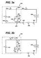
- FIG. 3 a and FIG. 3 bare schematic diagrams of the operation of the diaphragm air moving system of the present invention.
- FIG. 4is a diagrammatic axial cross-sectional view of a battery according to a second embodiment of the present invention.
- FIG. 5is a diagrammatic axial view of a battery according to a third embodiment of the present invention.
- FIG. 6is a schematic diagrams of the operation of the diaphragm air moving system of the present invention utilizing a piezoelectric diaphragm.
- the inventionmay be embodied in a metal-air battery or other type of fuel cell. It is well understood that many types of electrical devices may be powered by a metal-air battery.
- the cells of the metal-air batterymay be similar to those disclosed in commonly owned Ser. No. 08/299,997 or in commonly owned U.S. Pat. Nos. 5,356,729 or 5,641,588 or 5,569,551, which are incorporated herein by reference.
- the metal-air batterymay include one or more metal-air cells enclosed within a casing. Although the use of the invention with specific types of metal-air cells is disclosed, this invention should be understood as being applicable to any type of metal-air cell, whether primary or secondary, and to other types of fuel cells.
- FIG. 1is a preferred embodiment of the present invention illustrating a cylindrical battery 100 with a diaphragm air moving system 102 between an upper axial air chamber 104 a and a lower axial air chamber 104 b .
- the diaphragm air moving system 102 and a metal-air cell 106are enclosed within a conductive cylindrical casing 108 .
- the metal-air cell 106is composed of an anode material 110 in contact with the casing 108 , and a cylindrical air cathode 112 with a separator 113 between the anode material 110 and the air cathode 112 .
- the air cathode 112is electrically isolated from the casing 108 by annular cathode insulators 114 .
- the diameter of the chambers 104 a and 104 bis exaggerated to show detail. In practice, the diameter is minimized.
- One side of the air cathodes 112faces the upper and lower axial air chambers 104 a and 104 b .
- the opposing side of the air cathode 112faces the separator 113 which in turn faces the anode material 110 .
- a diaphragm air moving system 102is positioned in the casing 108 between an upper axial air chamber 104 a and a lower axial air chamber 104 b .
- the upper axial air chamber 104 a and a lower axial air chamber 104 btogether provide an interior air plenum.
- Arrows 115 , 116 , 118 , and 125represent a typical circulation of air or other gaseous oxygen source into, within, and out of the casing 108 to provide reactant air flow to the air cathodes 112 as a result of operation of the air moving system or in a manner described below.
- the casing 108isolates the metal-air cell 106 from the ambient air with the exception of a plurality of ventilation openings 128 and 130 .
- the casingpreferably is a conductive metal can.
- the casingmay be made of plastic, and the cell may be provided with an anode current collector and an anode terminal extending to the exterior of the casing.
- upper and lower ventilation openings 130 and 128permit the ambient air to communicate with the upper and lower axial air chambers 104 a and 104 b respectively. Both the upper axial air chamber 104 a and the lower axial air chamber 104 b must have at least one ventilation open per passageway.
- the number of ventilation openings 128 and 130is not as important as the aggregate size of the ventilation openings 128 and 130 in connection with their shape.
- the lower ventilation opening 128 through the casing 108is located on bottom of the battery 100 .
- a lower diffusion isolation tube 132connects to the lower ventilation opening 128 and extends from the lower ventilation opening 128 into the lower axial air chamber 104 b of the battery 100 .
- the upper ventilation opening 130 through the casing 108is located at the top of the battery 100 .
- An upper diffusion isolation tube 136connects to the upper ventilation opening 130 , and extends from the casing 108 into the upper axial air chamber 104 a of the battery 100 .
- the size, number, shape, or arrangement of the lower diffusion isolation tube 132 corresponding to the lower ventilation opening 128 and the upper diffusion isolation tube 136 corresponding to upper ventilation opening 130may be selected to further optimize the air flow to the metal-air cell 106 .
- the lower ventilation opening 128 and the upper ventilation opening 130are of sufficient size to admit and expel a quantity of air into and out of the casing 108 dependent upon the metal-air cell 106 power requirements.
- the diaphragm air moving system 102provides an increased air flow into and out of the upper and lower axial air chambers 104 a and 104 b adjacent to the air cathode 112 .
- the operation of the diaphragm air moving system 102occurs during certain high current draw modes of operation of the metal-air cell 106 and ceases during low current draw modes of operation. A detailed discussion of these two modes of operation in conjunction with the initiation of the air moving system 102 is provided below.
- a ferromagnetic rolling diaphragm 150is placed across the interior of the battery 100 perpendicular to air cathode 112 , and between the upper axial air chamber 104 a and the lower axial air chamber 104 b .
- the circular ferromagnetic rolling diaphragm 150is attached to the air cathode 112 through an annular diaphragm insulator 155 , thus electrically isolating the ferromagnetic rolling diaphragm 150 from the air cathode 112 at the point where it fastens to the air cathode 112 .
- the ferromagnetic rolling diaphragm 150may be made of a resilient material diaphragm with a ferromagnetic plate attached or may be formed of a resilient ferromagnetic material.
- the diaphragmmay be made of various flexible materials including a thermoplastic elastomer (TPE) such as Santoprene® thermoplastic rubber available from Advanced Elastomer Systems.
- TPEthermoplastic elastomer
- a perforated circular plate 160is placed across the interior of the battery 100 .
- the perforated plate 160is located within the lower axial air chamber 104 b , perpendicular to air cathode 112 , and parallel to the ferromagnetic rolling diaphragm 150 .
- the perforated plate 160is not insulated from the air cathode 112 , but rather is conductive and is connected to a cylindrical cathode current collector 111 placed longitudinally within the air cathode 112 .
- the perforations in the perforated plate 160allow air flow 116 to flow through the perforated plate and into and out of the lower axial air chamber 104 b.
- a coil 165is positioned between the ferromagnetic rolling diaphragm 150 and the perforated plate 160 .
- One end of the coil 165is electrically connected to the ferromagnetic diaphragm 150 through a flexible coil lead 170 .
- the opposite end of the coilis electrically connected to the perforated plate 160 .
- a terminal projection 138which is insulated from the conductive cylindrical casing 108 through the use of a terminal projection insulator 140 .
- a contact lead 180provides a connection between the terminal projection 138 and contacts 185 positioned to make electrical contact with the diaphragm 150 when the diaphragm is in a relaxed, upper position as shown in FIGS. 1 and 3 a .
- a resistor 175is placed between the cathode current collector 111 and the contact lead 180 .
- the load current (I L ) 192is drawn through two parallel paths comprising a resistor path corresponding to a resistor current (I R ) 194 and a coil path corresponding to a coil current (I C ) 196. However, if the contacts 185 are open, then there is no current in the coil path. Both currents originate from the cathode current collector 111 and sum together at the contact lead 180 to equal load current (I L ) 192.
- the resistor current (I R ) 194originates from the cathode current collector 111 , continues through the resistor 175 and then to contact lead 180 .
- the coil current (I C ) 196also originates with the cathode connector 111 , but continues through the perforated plate 160 , through coil 165 and then through the flexible coil lead 170 . From the flexible coil lead 170 , the coil current (I C ) 196 continues through the ferromagnetic rolling diaphragm 150 . With the contacts 185 closed, the coil current (I C ) 196 continues through the contacts 185 and then to the contact lead 180 .
- the resistor current (I R ) 194 and the coil current (I C ) 196sum together in the contact lead 180 to create the load current (I L ) 192 .
- the load current (I L ) 192continues out of the battery 100 from the contact lead 180 , through the terminal projection 138 and into the load 190 .
- the load current (I L ) 192will vary depending upon the demand placed upon the metal-air cell 106 by the load 190 .
- the magnitude of the load current (I L ) 192can be characterized as having two levels, herein described as a low current draw mode and a high current draw mode.
- the upper diffusion isolation tube 136 along with the lower diffusion isolation tube 132permit a predetermined low flow rate of air into the upper and lower axial air chambers 104 a and 104 b .
- This predetermined low flow rate of airis sufficient to service the needs of the air cathode 112 at a level which enables the battery 100 to provide energy to the load 190 , when the load 190 demands a load current 192 corresponding to a low current draw mode. Since the upper diffusion isolation tube 136 along with the lower diffusion isolation tube 132 are sufficient to provide air to the air cathode 112 , the operation of the diaphragm air moving system 102 is not necessary during the low current draw mode.
- the upper diffusion isolation tube 136 along with the lower diffusion isolation tube 132are not sufficient alone to service the needs of the air cathode 112 .
- the diaphragm air moving system 102In order to provide the necessary flow rate of air sufficient to service the needs of the air cathode 112 during the high current draw mode, the diaphragm air moving system 102 must be engaged.
- FIG. 2illustrates the dual mode feature of the battery 100 and the initiation of the diaphragm air mover 102 .
- I SWITCHis the level of load current 192 at which the operation of the diaphragm air moving system 102 is initiated.
- I HIGHis of a greater magnitude than I SWITCH .
- the diaphragm air moving system 102operates since the load current 192 is greater than I SWITCH .
- the load current 192 (I L ) during the stand-by modecorresponds to the I LOW level illustrated in FIG. 2 .
- the cellular telephoneeither receives a call or a user places a call using the cellular telephone.
- the energy needbegins at a low current draw mode corresponding to the stand-by mode and transitions to a high current draw mode corresponding to the transmit mode of the cellular telephone.
- the load current 192(I L ) passes through a level I SWITCH which is the level of load current 192 at which the operation of the diaphragm air moving system 102 is initiated. Therefore, the diaphragm air moving system 102 is engaged to provide the necessary flow rate of air sufficient to service the needs of the air cathode 112 during the transmit mode of the cellular telephone.
- a resulting coil current (I C ) 196will be drawn which is less than a predetermined level and will not create sufficient electromagnetic force to move the diaphragm 150 and thus will not cause the oscillation of the ferromagnetic rolling diaphragm 150 . If, however, the load 190 is greater than a specified magnitude corresponding to a high current draw mode, a resulting coil current (I C ) 196 will be drawn which is greater than a predetermined level and sufficient to oscillate the ferromagnetic rolling diaphragm 150 .
- the predetermined level of coil current (I C ) 196 capable of causing the oscillation of the ferromagnetic rolling diaphragm 150 , and below which the ferromagnetic rolling diaphragm 150 , does not oscillate,can be determined by the size of resistor 175 in coordination with load 190 .
- the size of the coil 165can be determined by the coil size necessary to create a magnetic field large enough to sufficiently pull the ferromagnetic rolling diaphragm 150 .
- the resistor 175is sized in order to cause a sufficient coil current (I C ) 196 for the high current draw mode.
- the coil current (I C ) 196 for the high current draw modemust be of sufficient magnitude to create a magnetic field large enough to sufficiently pull the ferromagnetic rolling diaphragm 150 .
- the load current (I L ) 192falls sufficiently below this level, the corresponding coil current (I C ) 196 must not be of sufficient magnitude to create a magnetic field large enough to sufficiently pull the ferromagnetic rolling diaphragm 150 .
- load current (I L ) 192is drawn from the cell 306 when load 190 is connected to battery 100 .
- the cell 306may be comprised of an gas depolarized electrochemical power source, such as a metal-air battery, or may be comprised of fuel cells of the type that are supplied with reactive gas such as hydrogen or methanol by an active air moving device.
- Load current (I L ) 192divides at node 210 into the coil current (I C ) 196 and the resistor current (I R ) 194 .
- load current (I L ) 192the load current (I L ) 192 continues to serve load 190 and then returns to the cell 306 , thus completing the electrical circuit.
- FIG. 3 bis an illustration of the system with the contacts 185 open.
- the coil current (I C ) 196will go to zero, though not instantaneously.
- the coil current (I C ) 196is at zero, the magnetic field attracting the ferromagnetic rolling diaphragm 150 will cease. With the magnetic field no longer present, the resiliency of the ferromagnetic rolling diaphragm 150 will return the ferromagnetic rolling diaphragm 150 to its original position.
- the contacts 185which were open will now re-close. With the contacts 185 now in the closed position, the coil current (I C ) 196 will be reestablished thus reestablishing the magnetic field and once again attracting the ferromagnetic rolling diaphragm 150 .
- This processwill repeat and cause the ferromagnetic rolling diaphragm 150 to oscillate as long as the coil current (I C ) 196 is available to the coil 165 and is greater or equal to a predetermined level sufficient to attract the ferromagnetic rolling diaphragm 150 .
- the coil and resistorcan be tuned to cause the ferromagnetic rolling diaphragm 150 to oscillate at a frequency not within the audible range of the human ear. This will allow the air mover to operate quietly with respect to human detection.
- the air moving system of the present inventioncan be applied to an electrical device having a single mode of operation.
- the low current draw modeoccurs when the device is “off” and draws no current.
- FIG. 4illustrating a second embodiment of the present invention comprising a battery 400 with a diaphragm air moving system 402 between an upper chamber 404 a and a lower chamber 404 b .
- the diaphragm air moving system 402 and a metal-air battery of cells 406are enclosed within a prismatic casing 408 .
- the metal-air battery of cells 406 having a cathode terminal 412 and an anode terminal 414includes a plurality of metal-air cells 410 .
- the diaphragm air moving system 402is positioned in the casing 408 between the upper chamber 404 a and the lower chamber 404 b.
- the casing 408isolates the metal-air battery of cells 406 from the ambient air with the exception of a ventilation opening 428 .
- the casingpreferably is a plastic material, or a metal can insulated from the interior components.
- the ventilation opening 428permits the ambient air to communicate with the lower chamber 404 b .
- the lower chamber 404 bmust have at least one ventilation opening 428 ; the number of ventilation openings is not as important as the aggregate size of the ventilation openings in connection with their shape.
- the lower ventilation opening 428is of sufficient size to admit and expel a quantity of air into and out of the casing 408 dependent upon the metal-air battery of cell's 406 power requirements.
- the ventilation opening 428 through the casing 408is located on bottom of the battery 400 .
- a diffusion isolation tube 432connects to the ventilation opening 428 and extends from the lower ventilation opening 428 into the lower chamber 404 b of the battery 400 .
- the diaphragm air moving system 402provides an increased air flow into and out of the lower chamber 404 b adjacent to the air cathodes of the metal-air cells 410 .
- the operation of the diaphragm air moving system 402occurs during certain high current draw modes of operation of the metal-air battery of cells 406 and ceases during low current draw modes of operation. A detailed discussion of these two modes of operation has been discussed previously.
- a conductive ferromagnetic rolling diaphragm 150is placed across the interior of the battery 400 above the lower chamber 404 b .
- the ferromagnetic rolling diaphragm 150is attached to the casing 408 .
- the diaphragmmay be formed in a rectangular shape, or may be a circular or ellipse mounted in a rectangular frame.
- a perforated plate 160is placed across the interior of the battery 400 .
- the perforated plate 160is located within the lower chamber 404 b and parallel to the ferromagnetic rolling diaphragm 150 .
- the perforated plate 160 and the ferromagnetic rolling diaphragm 150are not electrically connected to the casing 408 .
- the perforations in the perforated plate 160allow air to flow through the perforated plate and into and out of the lower chamber 404 b.
- a coil 165is positioned between the ferromagnetic rolling diaphragm 150 and the perforated plate 160 .
- One end of the coil 165is electrically connected to the ferromagnetic diaphragm 150 through a flexible coil lead 170 .
- the opposite end of the coilis electrically connected to the perforated plate 160 .
- a cathode terminal projection 415 and an anode terminal projection 420which are insulated form the casing 408 .
- a load current (I L ) 192is drawn from the metal-air battery of cells 406 .
- the load current (I L ) 192is drawn through two parallel paths comprising a resistor path corresponding to a resistor current (I R ) 194 and a coil path corresponding to a coil current (I C ) 196 . Both currents originate from the cathode terminal 412 and sum together at the cathode terminal projection 415 to equal load current (I L ) 192 .
- the resistor current (I R ) 194originates from the cathode terminal 412 , continues through the resistor 175 and then to the cathode terminal projection 415 .
- the coil current (I C ) 196also originates with the cathode terminal 412 , but continues through the perforated plate 160 , through coil 165 and then through the flexible coil lead 170 . From the flexible coil lead 170 , the coil current (I C ) 196 continues through the ferromagnetic rolling diaphragm 150 . If the contacts 185 are closed, the coil current (I C ) 196 continues through the contacts 185 and then to the contact lead 180 .
- the resistor current (I R ) 194 and the coil current (I C ) 196sum together in the cathode terminal projection 415 to create the load current (I L ) 192 .
- the load current (I L ) 192continues out of the battery 400 from the cathode terminal projection 415 , and into the load 190 .
- the diaphragm air moving system 402operates in similar fashion to the system discussed in the sections on the operation of the air mover and the dual mode feature above.
- FIG. 5illustrates a third embodiment of the present invention comprising an electrical device 500 .
- an air moving system 502is contained within the electrical device 500 and not within a metal-air battery.
- the electrical device casing 508defines a load chamber 501 for the electrical components of the device and a diaphragm air moving system 502 which comprises an upper chamber 504 a and a lower chamber 504 b separated by a diaphragm 150 .
- the chamber 504 bis atmospherically isolated from the other chambers.
- the diaphragm air moving system 502is enclosed within the electrical device casing 508 .
- a metal-air battery 506is contained in a cylindrical or prismatic battery casing 509 which is mateably received within a battery chamber 511 defined in to the electrical device casing 508 adjacent to the lower air mover chamber 504 b .
- the battery casing 509includes one or more metal-air cells 510 , and defines a projection 513 that is tightly but moveably received within a mating opening 515 of the chamber 504 b when the battery casing 509 is inserted into the chamber 511 .
- the projection 513includes a battery cathode terminal 512 and a battery anode terminal 514 positioned and spaced apart on the sides of the projection.
- the battery cathode terminal 512makes electrical contact with an air mover cathode terminal 516 and the battery anode terminal 514 makes electrical contact with an air mover cathode terminal 518 positioned within the opening 515 .
- the projection 519defines an isolation passageway 514 into the battery housing 509 .
- the casings 508 and 509are preferably made of a plastic material, or are made of metal insulated from the interior components.
- the battery casing 509optionally may be held in chamber 511 by a door, latch, detent, or the like (not shown).
- the ventilation opening 528permits the ambient air to communicate with a battery chamber 504 c .
- the ventilation opening 528 through the battery casing 509is located on on a surface exposed to the ambient air.
- a diffusion isolation tube 532connects to the ventilation opening 528 and extends from the lower ventilation opening 528 into the batter chamber 504 c of the battery casing 509 .
- the battery chamber 504 cmust have at least one ventilation opening 528 ; and associated isolation passageway 532 the number of ventilation openings is not as important as the aggregate size of the ventilation openings in connection with their shape.
- the lower ventilation opening 528 and associated isolation tube 532are of sufficient size to admit and expel a quantity of air into and out of the casing 509 dependent upon the metal-air battery of cell's 506 power requirements. Air is caused to communicate between lower air mover chamber 504 b and the battery chamber 504 c through the passageway 519 when the air mover is operating.
- the diaphragm air moving system 502provides an increased air flow into and out of the battery chamber 504 c adjacent to the air cathodes of the metal-air cells 510 .
- the operation of the diaphragm air moving system 502occurs during certain high current draw modes of operation of the metal-air battery of cells 506 and ceases during low current draw modes of operation. These two modes of operation have been discussed previously.
- the conductive ferromagnetic rolling diaphragm 150is placed within the electrical device 500 to separate the upper and lower chambers 504 a and 504 b .
- the ferromagnetic rolling diaphragm 150is attached to the casing 508 . If the chambers are prismatic, the diaphragm may be formed in a rectangular shape, or may be a circular or ellipse mounted in a rectangular frame. If the chambers are cylindrical, the diaphragm is preferably circular.
- the ferromagnetic rolling diaphragm 150is not electrically connected to the casing 508 .
- a vent 529equalizes pressure in the upper chamber 504 a . The vent 529 can lead either to the outside of the device casing 508 as shown, or to the load chamber 501 of the casing 508 .
- a coil 165is positioned in proximity to the ferromagnetic rolling diaphragm 150 .
- One end of the coil 165is electrically connected to the ferromagnetic diaphragm 150 through a flexible coil lead 170 .
- the opposite end of the coilis electrically connected to the air mover cathode terminal 516 . It should be understood that the coil can be placed on either side of the diaphragm, in this as well as previous embodiments.
- a cathode terminal projection 520 and an anode terminal projection 522which are insulated from the casing 508 .
- a load current (I L ) 192is drawn from the metal-air battery of cells 506 .
- the load current (I L ) 192is drawn through two parallel paths comprising a resistor path corresponding to a resistor current (I R ) 194 and a coil path corresponding to a coil current (I C ) 196 . Both currents originate from the battery cathode terminal 512 and sum together at the cathode terminal projection 520 to equal load current (I L ) 192 .
- the resistor current (I R ) 194originates from the battery cathode terminal 512 , continues through the resistor 175 and then to the cathode terminal projection 520 .
- the coil current (I C ) 196also originates with the cathode terminal 512 , but continues through the coil 165 and then through the flexible coil lead 170 . From the flexible coil lead 170 , the coil current (I C ) 196 continues through the ferromagnetic rolling diaphragm 150 . If the contacts 185 are closed, the coil current (I C ) 196 continues through the contacts 185 and then to the contact lead 180 .
- the resistor current (I R ) 194 and the coil current (I C ) 196sum together in the cathode terminal projection 520 to create the load current (I L ) 192 .
- the load current (I L ) 192continues out of the the cathode terminal projection 520 and into the load 190 .
- the diaphragm air moving system 502operates in similar fashion to the system discussed in the sections on the operation of the air mover and the dual mode feature above.
- FIG. 6illustrates an alternative to the diaphragm 150 , namely, a electrically activated diaphragm 650 , and the operation of the diaphragm 650 in the air moving system 102 .
- the electrically activated diaphragm 650can be made of flexible piezoelectric material, electrostatic material, or electroactive polymers (EAPS). Examples of EAPS include bending actuators or ionomers and longitudinal electrostatically driven polymers. Bending actuators or ionomers can include perfluorinated ion exchange membrane platinum composites (IMPC) based on a processed Nafion® film manufactured by DuPont. EAPS can bend, stretch, extend, or displace in a predetermined direction in response to an applied electrical current or voltage.
- IMPCperfluorinated ion exchange membrane platinum composites
- EAPSprovide greater response time, lower material density, lower power consumption, improved fatigue characteristics, mass production capabilities, and the lack of poling needed when compared to conventional piezoelectric materials, as well as cost and space savings advantages over other conventional materials.
- the load current (I L ) 192is drawn from metal-air cell 106 when load 190 is connected to battery 100 .
- Load current (I L ) 192divides at node 210 into the diaphragm current (I D ) 696 and the resistor current (I R ) 194 . Once the two currents pass through their respective parallel paths, they sum together at node 220 to a magnitude equal to load current (I L ) 192 . After node 220 , the load current (I L ) 192 continues to serve load 190 and then returns to the metal-air cell 106 , thus completing the electrical circuit.
- the diaphragm current (I D ) 696must be of a magnitude to cause the electrically activated diaphragm 650 to deform.
- the electrically activated diaphragm 650is deformed in such a way as to pull the electrically activated diaphragm 650 away from the contacts 185 into a position shown in dashed lines as 650 ′, thus causing the contacts to open.
- the flexible diaphragm lead 670allows the electrically activated diaphragm 650 to remain electrically connected to the node 210 during movement of the electrically activated diaphragm 650 .
- the diaphragm current (I D ) 696will go to zero.
- the electric current causing the diaphragm to deformwill cease. With this current no longer present, the electrically activated diaphragm 650 will return to its original position.
- the contacts 185When the electrically activated diaphragm 650 returns to its original position, the contacts 185 will now re-close. With the contacts 185 now in the closed position, the diaphragm current (I D ) 696 will be reestablished thus reestablishing the current through the electrically activated diaphragm 650 and once again deforming the electrically activated diaphragm 650 . This process will repeat and cause the electrically activated diaphragm to oscillate between the solid and dashed line positions as long as the diaphragm current (I D ) 696 is available to the electrically activated diaphragm 650 and is greater or equal to a predetermined level sufficient to deform the electrically activated diaphragm 650 .
- the circuitcan be tuned to cause the electrically activated diaphragm 650 to oscillate at a frequency not within the audible range of the human ear. This will allow the air mover to operate quietly with respect to human detection.
- the air moving system of the present inventioncan be applied to an electrical device having a single mode of operation.
- the deviceeither is “off” and draws no current, or is in a high current draw mode.
- the coil current I C 196 needed to oscillate the conductive ferromagnetic diaphragm 150may typically be less than or equal to 50 mA, and preferably about 20 mA.
- the voltage across the coil necessary for oscillationis approximately 1 V when taken in conjunction with the aforementioned currents, but may vary depending on the characteristics of the coil.
- the minimum diaphragm current I D 696 needed to oscillate an electrically activated diaphragm 650 when the diaphragm is made of a piezoelectric materialmay typically be less than or equal to about 1 mA, and preferably about 0.1 to 0.2 mA.
- the minimum current I D needed to oscillate an EAPS type diaphragmmay typically fall within a range between about 50 mA and 1 mA, and preferably within a range between about 20 mA and 0.1 mA.
- the voltage across these types diaphragms necessary for oscillationis approximately 5 V when taken in conjunction with the aforementioned currents, again depending on the characteristics of the diaphragm.
- the isolation passagewaysare sized to allow a selected level of air flow when the air mover is off.
- the threshold current necessary to oscillate the diaphragmcan be approximately 20 mA.
- the diffusion tubesshould be designed to allow enough air into the air chamber to maintain approximately a 10% 02 content within the air chamber. In order to maintain this 02 content with two diffusion tubes, the diffusion tubes should be designed to have a cross sectional area to length ratio of approximately 0.03.
- the ratio for each tubewould change if only one diffusion tube is used or if more than one cell is being isolated by the tube or tubes.
- the diffusion tubessupply sufficient oxygen without an air mover.
- the current drawpasses through the threshold and the air mover becomes operational.
- the isolating passageways 132 , 136 , 432 , 532 , and 519 described aboveare preferably constructed and arranged to allow a sufficient amount of airflow therethrough while the air moving device is operating so that a sufficient output current, typically at least 50 ma, and preferably at least 130 ma can be obtained from the metal-air cells.
- the isolating passagewaysare preferably constructed to limit the airflow and diffusion therethrough to a level consistent with the needs of the battery-powered product to which the cells are connected.
- the isolation passagewayis sized such that the drain current that the metal-air cells are capable of providing to a load while the air moving device is not forcing airflow through the isolating passageways is smaller than the output current by a factor of about 50 or greater.
- the isolating passagewaysare preferably constructed to provide an “isolation ratio” of more than 50 to 1.
- the “isolation ratio”is the ratio of the rate of water loss or gain by a cell while its oxygen electrodes are fully exposed to the ambient air, as compared to the rate of the water loss or gain of the cell while its oxygen electrodes are isolated from the ambient air, except through one or more limited openings.
- the water loss from a cell having an oxygen electrode fully exposed to the ambient airshould be more than 100 times greater than the water loss from a cell having an oxygen electrode that is isolated from the ambient air, except through one or more isolating passageways of the type described above. In this example, an isolation ratio of more than 100 to 1 should be obtained.
- each of the isolating passagewayspreferably has a width that is generally perpendicular to the direction of flow therethrough, and a length that is generally parallel to the direction of flow therethrough.
- the length and the widthare selected to substantially eliminate airflow and diffusion through the isolating passageways while the air moving device is not forcing airflow through the isolating passageways.
- the lengthis greater than the width, and more preferably the length is greater than about twice the width.
- the use of larger ratios between length and widthare preferred. Depending upon the nature of the metal-air cells, the ratio can be more than 200 to 1. However, the preferred ratio of length to width is about 10 to 1.
- the isolating passagewayscould form only a portion of the path air must take between the ambient environment and the oxygen electrodes.
- Each of the isolating passagewaysmay be defined through the thickness of the battery housing or cell case, but preferably they are in the form of tubes as described above. In either case, the isolating passageways may be cylindrical, and for some applications each can have a length of about 0.3 to 2.5 inches or longer, with about 0.88 to 1.0 inches preferred, and an inside diameter of about 0.03 to 0.3 inches, with about 0.09 to 0.19 inches preferred.
- the total open area of each isolating passageway for such applications, measured perpendicular to the direction of flow therethrough,is therefore about 0.0007 to 0.5 square inches.
- the isolating passagewayseach can have a length of about 0.1 to 0.3 inches or longer, with about 0.1 to 0.2 inches preferred, and an inside diameter of about 0.01 to 0.05 inches, with about 0.015 inches preferred.
- the diffusion tubesare opened somewhat, to a larger ratio of cross sectional area to length.
- the isolation ratiopreferably may be as low as about 20:1. In this way, some cell life is compromised in order to provide the dual mode operation of the cells.
- the needed ratio of cross sectional area to length for each diffusion tubedepends on the amount of current desired in the stand-by mode, the number of tubes, and amount of air cathode area of the one or more cells within a battery housing isolated by the tubes, and can be calculated based on the laws or gas diffusion and the electrochemical reactions at the cathode, known to those skilled in the art. These laws can be used to demonstrate that 107.2 amp-hours can be produced per mole of oxygen in the air admitted through the tubes to the cathode.
- the preferred dimensions for a particular applicationwill be related to the geometry of the passageways and the cathode plenums, the particular air mover utilized, and the volume or air needed to operate the cells at a desired level.
- the isolating passagewaysare not necessarily cylindrical, as any cross-sectional shape that provides the desired isolation is suitable.
- the isolating passagewaysneed not be uniform along their length, so long as at least a portion of each isolating passageway is operative to provided the desired isolation. Further, the isolating passageways may be straight or curved along their length.
- the inventionprovides an improved air moving device for metal-air cells that occupies a minimal amount of the volume available for battery chemistry, is usable with advanced systems for isolating the air electrodes when power is not being drawn from the metal air cell, requires either simple or no control logic circuitry, is quiet, and consumes power at a relatively low rate. Further, the system is responsive to a dual level load, detecting the change in the load level and activating the air mover during the high current draw mode and de-activating the air mover during the low current draw mode. It will be understood that the preferred embodiment has been disclosed by way of example, and that other modifications may occur to those skilled in the art without departing from the scope and spirit of the appended claims.
Landscapes
- Engineering & Computer Science (AREA)
- Manufacturing & Machinery (AREA)
- Chemical & Material Sciences (AREA)
- Chemical Kinetics & Catalysis (AREA)
- Electrochemistry (AREA)
- General Chemical & Material Sciences (AREA)
- Life Sciences & Earth Sciences (AREA)
- Sustainable Development (AREA)
- Sustainable Energy (AREA)
- Hybrid Cells (AREA)
Abstract
Description
Claims (22)
Priority Applications (4)
| Application Number | Priority Date | Filing Date | Title |
|---|---|---|---|
| US09/602,187US6824915B1 (en) | 2000-06-12 | 2000-06-12 | Air managing systems and methods for gas depolarized power supplies utilizing a diaphragm |
| PCT/US2001/018643WO2001097318A1 (en) | 2000-06-12 | 2001-06-11 | Air managing systems and methods for gas depolarized power supplies utilizing a diaphragm |
| AU2001266801AAU2001266801A1 (en) | 2000-06-12 | 2001-06-11 | Air managing systems and methods for gas depolarized power supplies utilizing a diaphragm |
| TW090113467ATW531930B (en) | 2000-06-12 | 2001-06-21 | Air managing systems and methods for gas depolarized power supplies utilizing a diaphragm |
Applications Claiming Priority (1)
| Application Number | Priority Date | Filing Date | Title |
|---|---|---|---|
| US09/602,187US6824915B1 (en) | 2000-06-12 | 2000-06-12 | Air managing systems and methods for gas depolarized power supplies utilizing a diaphragm |
Publications (1)
| Publication Number | Publication Date |
|---|---|
| US6824915B1true US6824915B1 (en) | 2004-11-30 |
Family
ID=24410328
Family Applications (1)
| Application Number | Title | Priority Date | Filing Date |
|---|---|---|---|
| US09/602,187Expired - LifetimeUS6824915B1 (en) | 2000-06-12 | 2000-06-12 | Air managing systems and methods for gas depolarized power supplies utilizing a diaphragm |
Country Status (4)
| Country | Link |
|---|---|
| US (1) | US6824915B1 (en) |
| AU (1) | AU2001266801A1 (en) |
| TW (1) | TW531930B (en) |
| WO (1) | WO2001097318A1 (en) |
Cited By (10)
| Publication number | Priority date | Publication date | Assignee | Title |
|---|---|---|---|---|
| US7607470B2 (en) | 2005-11-14 | 2009-10-27 | Nuventix, Inc. | Synthetic jet heat pipe thermal management system |
| US20100124687A1 (en)* | 2008-11-18 | 2010-05-20 | Eveready Battery Company, Inc. | Fluid Manager Having Fluid Injection Primer for a Fluid Consuming Battery |
| US20100150753A1 (en)* | 2008-12-15 | 2010-06-17 | Siemens Ag | Oscillating Diaphragm Fan Having Coupled Subunits and a Housing Having an Oscillating Diaphragm Fan of this Type |
| US8030886B2 (en) | 2005-12-21 | 2011-10-04 | Nuventix, Inc. | Thermal management of batteries using synthetic jets |
| WO2019222704A1 (en)* | 2018-05-17 | 2019-11-21 | Giner Life Sciences, Inc. | Electrolytic gas generator with combined lead and gas port terminals |
| US10557691B2 (en) | 2016-11-15 | 2020-02-11 | Giner Life Sciences, Inc. | Self-regulating electrolytic gas generator and implant system comprising the same |
| US11033666B2 (en) | 2016-11-15 | 2021-06-15 | Giner Life Sciences, Inc. | Percutaneous gas diffusion device suitable for use with a subcutaneous implant |
| US11047508B2 (en) | 2017-03-30 | 2021-06-29 | Donaldson Company, Inc. | Vent with relief valve |
| US11642501B2 (en) | 2017-05-04 | 2023-05-09 | Giner, Inc. | Robust, implantable gas delivery device and methods, systems and devices including same |
| US11701215B2 (en) | 2013-09-24 | 2023-07-18 | Giner, Inc. | System for gas treatment of a cell implant |
Families Citing this family (3)
| Publication number | Priority date | Publication date | Assignee | Title |
|---|---|---|---|---|
| US7332238B2 (en) | 2002-09-06 | 2008-02-19 | The Gillette Company | Electrochemical cells and systems |
| TWI416791B (en)* | 2007-07-04 | 2013-11-21 | Wistron Corp | A coupling structure of fuel cells is disclosed |
| US10763528B2 (en)* | 2017-09-18 | 2020-09-01 | GM Global Technology Operations LLC | Operation of a fuel cell stack to prevent low oxygen concentrations in a surrounding enclosed space |
Citations (134)
| Publication number | Priority date | Publication date | Assignee | Title |
|---|---|---|---|---|
| US737613A (en) | 1902-12-06 | 1903-09-01 | Halsey Electric Generator Company | Electric battery. |
| US1112861A (en) | 1912-08-15 | 1914-10-06 | Gould Storage Battery Co | Storage battery. |
| US1285659A (en) | 1916-03-20 | 1918-11-26 | Bruce Ford | Storage-battery ventilation for submarines. |
| US2273244A (en) | 1940-04-03 | 1942-02-17 | Electric Storage Battery Co | Storage battery cell |
| US2275281A (en) | 1936-12-16 | 1942-03-03 | Berl Ernst | Depolarization means |
| US2468430A (en) | 1943-04-12 | 1949-04-26 | Hartford Nat Bank & Trust Co | Casing with pushbutton valve for air depolarized cells |
| US3072284A (en) | 1960-06-09 | 1963-01-08 | Dairy Equipment Co | Vent |
| US3160528A (en) | 1961-11-30 | 1964-12-08 | Exxon Research Engineering Co | Portable power plant |
| US3395047A (en) | 1965-08-30 | 1968-07-30 | Monsanto Res Corp | Gasketed electrode fuel cell |
| FR1575640A (en) | 1967-03-30 | 1969-07-25 | ||
| US3473963A (en) | 1967-02-23 | 1969-10-21 | United Aircraft Corp | Fuel cell system with automatic control means |
| US3523830A (en) | 1966-09-26 | 1970-08-11 | Inst Gas Technology | Fuel cell and method of controlling the temperature of said cell |
| US3554810A (en) | 1967-04-12 | 1971-01-12 | Solomon Zaromb | Metal-oxygen power source |
| US3576677A (en) | 1967-05-23 | 1971-04-27 | United Aircraft Corp | Fuel cell process air control |
| US3613732A (en) | 1969-07-17 | 1971-10-19 | Robertshaw Controls Co | Temperature-responsive valve operators |
| US3615839A (en) | 1968-07-12 | 1971-10-26 | United Aircraft Corp | Fuel cell system with recycle stream |
| US3629009A (en) | 1969-05-07 | 1971-12-21 | Union Carbide Corp | Auxiliary component package for oxygen-metal batteries |
| US3632449A (en) | 1969-06-30 | 1972-01-04 | Michel N Yardney | Method of making and operating a gas-depolarized cell |
| US3666562A (en) | 1968-03-15 | 1972-05-30 | Varta Ag | Fuel cell with control system and method |
| US3740636A (en) | 1971-11-05 | 1973-06-19 | Us Navy | Charge regulator and monitor for spacecraft solar cell/battery system control |
| US3744516A (en) | 1970-03-04 | 1973-07-10 | R Rowe | Combined filling device and vent cut-off valve for electric storage cells |
| US3801372A (en) | 1971-08-18 | 1974-04-02 | United Aircraft Corp | Fuel cell system comprising separate coolant loop and sensing means |
| US3850695A (en) | 1972-02-05 | 1974-11-26 | Bosch Gmbh Robert | Voltage regulator system for use with fuel cell battery |
| US3871920A (en) | 1972-08-25 | 1975-03-18 | Accumulateurs Fixes | Air depolarized cell |
| US3909302A (en) | 1973-06-21 | 1975-09-30 | Tyco Laboratories Inc | Vent cap for batteries |
| US4052534A (en) | 1973-05-03 | 1977-10-04 | General Battery Corporation | Battery vent plug |
| US4063826A (en) | 1975-05-20 | 1977-12-20 | Waldemar Riepe | Flexible, oscillating blade liquid pump |
| US4118544A (en) | 1977-09-28 | 1978-10-03 | P.R. Mallory & Co. Inc. | Metal-air depolarized cell having restricted gas passageway |
| US4139846A (en) | 1977-06-30 | 1979-02-13 | Pittway Corporation | Method and apparatus for supervising battery energy level |
| US4177327A (en) | 1978-11-20 | 1979-12-04 | P. R. Mallory & Co. Inc. | Metal-air battery having electrically operated air access vent cover |
| US4207514A (en) | 1977-11-21 | 1980-06-10 | Energy Research Corporation | System and apparatus for monitoring or controlling secondary battery operation |
| FR2353142B1 (en) | 1976-05-26 | 1980-09-05 | Comp Generale Electricite | |
| US4221644A (en) | 1979-08-14 | 1980-09-09 | Diamond Shamrock Corporation | Air-depolarized chlor-alkali cell operation methods |
| US4246324A (en) | 1979-04-09 | 1981-01-20 | Diamond Shamrock Technologies S.A. | Consumable replaceable anodes for batteries |
| US4254190A (en) | 1979-10-01 | 1981-03-03 | Solomon Zaromb | Electrochemical power generation apparatus and methods |
| US4262062A (en) | 1980-03-24 | 1981-04-14 | Timex Corporation | Metal-air battery with environment control for intermittent high current demand |
| US4269906A (en) | 1977-09-12 | 1981-05-26 | Aktiebolaget Tudor | Pump device |
| US4310604A (en) | 1980-07-14 | 1982-01-12 | Energy Research Corporation | Fuel cell system and temperature control therefore |
| US4316185A (en) | 1980-07-17 | 1982-02-16 | General Electric Company | Battery monitor circuit |
| US4318092A (en) | 1978-06-08 | 1982-03-02 | Minnesota Mining And Manufacturing Company | Means for checking battery voltage level |
| US4399200A (en) | 1981-11-05 | 1983-08-16 | Energy Development Associates, Inc. | Device for controlling a pump in a storage battery |
| US4405387A (en) | 1982-02-05 | 1983-09-20 | Bbc Brown, Boveri & Company Limited | Process to produce a reversible two-way shape memory effect in a component made from a material showing a one-way shape memory effect |
| US4448858A (en) | 1982-03-26 | 1984-05-15 | California Institute Of Technology | Chemically rechargeable battery |
| US4484691A (en) | 1975-11-03 | 1984-11-27 | Duracell Inc. | Pressure release device |
| US4490443A (en) | 1982-10-25 | 1984-12-25 | Accumulatorenwerke Hoppecke Carl Zoellner & Sohn Gmbh & Co. Kg | Battery having electrolyte supply reservoir and activation tank disposed in a battery housing |
| US4493880A (en) | 1983-12-19 | 1985-01-15 | Gould Inc. | Battery switch |
| US4521497A (en) | 1984-05-18 | 1985-06-04 | Lth Associates, Ltd. | Electrochemical generators and method for the operation thereof |
| US4560626A (en) | 1982-09-20 | 1985-12-24 | The United States Of America As Represented By The United States Department Of Energy | Rapidly refuelable fuel cell |
| US4642273A (en) | 1983-05-19 | 1987-02-10 | Mitsubishi Denki Kabushiki Kaisha | Reformer reaction control apparatus for a fuel cell |
| US4648807A (en) | 1985-05-14 | 1987-03-10 | The Garrett Corporation | Compact piezoelectric fluidic air supply pump |
| US4687714A (en) | 1986-02-04 | 1987-08-18 | Rayovac Corporation | Case for metal/air electrochemical cells, and cells and lantern batteries thereof |
| US4729930A (en) | 1987-05-29 | 1988-03-08 | International Fuel Cells Corporation | Augmented air supply for fuel cell power plant during transient load increases |
| US4745038A (en) | 1983-11-10 | 1988-05-17 | Westinghouse Electric Corp. | Integrated gasification iron-air electrical system |
| US4855195A (en) | 1988-07-11 | 1989-08-08 | Eveready Battery Company, Inc. | Electrochemical cell with internal circuit interrupter |
| US4857885A (en) | 1987-03-26 | 1989-08-15 | Celaya, Emparanza Y Galdos, S.A. (Cegasa) | Battery couplings to portable signals with long periods out of service |
| US4859545A (en) | 1988-05-05 | 1989-08-22 | International Fuel Cells Corporation | Cathode flow control for fuel cell power plant |
| US4894295A (en) | 1988-09-14 | 1990-01-16 | Cheiky Michael C | Metal-alloy air battery |
| US4904548A (en) | 1987-08-03 | 1990-02-27 | Fuji Electric Co., Ltd. | Method for controlling a fuel cell |
| US4908281A (en) | 1987-09-25 | 1990-03-13 | Alcan International Limited | Metal/air battery with recirculating electrolyte |
| US4913983A (en) | 1988-09-13 | 1990-04-03 | Dreisbach Electromotive, Inc. | Metal-air battery power supply |
| US4938742A (en) | 1988-02-04 | 1990-07-03 | Smits Johannes G | Piezoelectric micropump with microvalves |
| US4943750A (en) | 1987-05-20 | 1990-07-24 | Massachusetts Institute Of Technology | Electrostatic micromotor |
| US4957826A (en) | 1989-04-25 | 1990-09-18 | Dreisbach Electromotive, Inc. | Rechargeable metal-air battery |
| WO1990011625A1 (en) | 1989-03-23 | 1990-10-04 | Alcan International Limited | Metal/air battery with seeded recirculating electrolyte |
| US5011380A (en) | 1989-01-23 | 1991-04-30 | University Of South Florida | Magnetically actuated positive displacement pump |
| US5047961A (en) | 1988-05-31 | 1991-09-10 | Simonsen Bent P | Automatic battery monitoring system |
| US5066204A (en) | 1989-07-07 | 1991-11-19 | Rena S.A. | Diaphragm pump |
| US5069986A (en) | 1989-10-26 | 1991-12-03 | Motorola, Inc. | Selective discharge limiting seal for a battery |
| US5085562A (en) | 1989-04-11 | 1992-02-04 | Westonbridge International Limited | Micropump having a constant output |
| US5141826A (en) | 1990-09-21 | 1992-08-25 | Licentia Patent-Verwaltungs Gmbh | High-energy battery with a temperature regulating medium |
| US5183222A (en) | 1991-08-12 | 1993-02-02 | Tacticon Corp. | Electric powered tip-driven fan with metal/air battery assembly therefor |
| US5185549A (en)* | 1988-12-21 | 1993-02-09 | Steven L. Sullivan | Dipole horn piezoelectric electro-acoustic transducer design |
| US5191274A (en) | 1989-10-26 | 1993-03-02 | Motorola, Inc. | Method and apparatus for controlling the self-discharge rate of a battery |
| US5196275A (en) | 1990-07-19 | 1993-03-23 | Electric Fuel Limited | Electrical power storage apparatus |
| US5208526A (en) | 1990-07-19 | 1993-05-04 | Luz Electric Fuel Israel Ltd. | Electrical power storage apparatus |
| US5211371A (en) | 1991-07-22 | 1993-05-18 | Advanced Control Technologies, Inc. | Linearly actuated valve |
| WO1993018556A1 (en) | 1992-03-13 | 1993-09-16 | Ballard Power Systems Inc. | Constant voltage fuel cell with improved reactant supply and control system |
| WO1993019495A1 (en) | 1992-03-16 | 1993-09-30 | Aer Energy Resources, Inc. | Metal-air power supply and air-manager system, and metal-air cell for use therein |
| US5258239A (en) | 1992-04-22 | 1993-11-02 | Brother Kogyo Kabushiki Kaisha | Metal-air cell having a piezoelectric air-supply pump |
| WO1994002966A2 (en) | 1992-07-17 | 1994-02-03 | Cheiky Michael C | Air manager system for metal-air battery |
| WO1994008358A1 (en) | 1992-10-02 | 1994-04-14 | Voltek, Inc. | Electrochemical power generating system |
| US5304431A (en) | 1992-05-20 | 1994-04-19 | Schumm Jr Brooke | Fluid depolarized electrochemical battery with automatic valve |
| US5306579A (en) | 1992-10-30 | 1994-04-26 | Aer Energy Resources, Inc. | Bifunctional metal-air electrode |
| US5325880A (en) | 1993-04-19 | 1994-07-05 | Tini Alloy Company | Shape memory alloy film actuated microvalve |
| US5328777A (en) | 1992-07-14 | 1994-07-12 | Aer Energy Resources, Inc. | Cathode cover for metal-air cell |
| US5356729A (en) | 1993-06-15 | 1994-10-18 | Aer Energy Resources, Inc. | Diffusion controlled air manager for metal-air battery |
| US5362577A (en) | 1993-06-04 | 1994-11-08 | Aer Energy Resources, Inc. | Diffusion vent for a rechargeable metal-air cell |
| WO1994025991A2 (en) | 1993-04-30 | 1994-11-10 | Aer Energy Resources, Inc. | Cathode air recirculation and moisture control |
| US5398011A (en) | 1992-06-01 | 1995-03-14 | Sharp Kabushiki Kaisha | Microrelay and a method for producing the same |
| US5411644A (en) | 1993-11-03 | 1995-05-02 | Neukermans; Armand P. | Method of operated dual pump getter and oxidant sensor and regulator |
| US5417235A (en) | 1993-07-28 | 1995-05-23 | Regents Of The University Of Michigan | Integrated microvalve structures with monolithic microflow controller |
| US5434016A (en) | 1993-06-07 | 1995-07-18 | Daimler-Benz Ag | Process and apparatus for supplying air to a fuel cell system |
| US5449569A (en) | 1992-05-20 | 1995-09-12 | Schumm, Jr.; Brooke | Fluid depolarized battery with improved automatic valve |
| US5466932A (en) | 1993-09-22 | 1995-11-14 | Westinghouse Electric Corp. | Micro-miniature piezoelectric diaphragm pump for the low pressure pumping of gases |
| US5486429A (en) | 1995-04-24 | 1996-01-23 | Aer Energy Resources, Inc. | Diffusion vent for a rechargeable metal-air cell |
| US5506067A (en) | 1995-04-04 | 1996-04-09 | Aer Energy Resources, Inc. | Rechargeable electrochemical cell and cell case therefor with vent for use in internal recombination of hydrogen and oxygen |
| US5522712A (en) | 1993-12-08 | 1996-06-04 | Winn; Ray | Low-powered cooling fan for dissipating heat |
| US5529465A (en) | 1991-09-11 | 1996-06-25 | Fraunhofer-Gesellschaft Zur Forderung Der Angewandten Forschung E.V. | Micro-miniaturized, electrostatically driven diaphragm micropump |
| US5536590A (en) | 1994-09-30 | 1996-07-16 | Dreisbach Electromotive, Inc. | Portable battery for use externally of an electronic device |
| US5554452A (en) | 1994-09-22 | 1996-09-10 | Matsi, Inc. | Metal-air batteries having improved air access valves |
| US5560999A (en) | 1993-04-30 | 1996-10-01 | Aer Energy Resources, Inc. | Air manager system for recirculating reactant air in a metal-air battery |
| US5563004A (en) | 1995-03-21 | 1996-10-08 | Aer Energy Resources, Inc. | Rechargeable metal-air electrochemical cell with hydrogen recombination and end-of-charge indicator |
| US5567284A (en) | 1993-09-18 | 1996-10-22 | Friwo Silberkraft Gesellschaft Fuer Batterietechnik Mbh | Electrochemical actuator |
| US5569551A (en) | 1995-04-24 | 1996-10-29 | Aer Energy Resources Inc. | Dual air elecrtrode cell |
| US5599174A (en) | 1994-05-18 | 1997-02-04 | Huntleigh Technology Plc. | Diaphragm pump with magnetic actuator |
| US5607292A (en)* | 1995-07-19 | 1997-03-04 | Rao; Dantam K. | Electromagnetic disk pump |
| US5619177A (en) | 1995-01-27 | 1997-04-08 | Mjb Company | Shape memory alloy microactuator having an electrostatic force and heating means |
| US5622482A (en) | 1994-10-31 | 1997-04-22 | Daewood Electronics, Co., Ltd. | Pump using shape memory alloys |
| WO1997015090A2 (en) | 1995-10-18 | 1997-04-24 | Aer Energy Resources, Inc. | Diffusion controlled air vent and recirculation air manager for a metal-air battery |
| US5639568A (en) | 1995-10-16 | 1997-06-17 | Aer Energy Resources, Inc. | Split anode for a dual air electrode cell |
| US5641588A (en) | 1994-09-01 | 1997-06-24 | Aer Energy Resources, Inc. | Portable battery with a retrofitting projection and wrist rest for use externally of an electronic device |
| US5641585A (en) | 1995-03-21 | 1997-06-24 | Lockheed Idaho Technologies Company | Miniature ceramic fuel cell |
| US5678647A (en) | 1994-09-07 | 1997-10-21 | Westinghouse Electric Corporation | Fuel cell powered propulsion system |
| US5691075A (en) | 1995-06-13 | 1997-11-25 | Sulzer Innotec Ag | High temperature fuel cell |
| US5691074A (en) | 1995-10-18 | 1997-11-25 | Aer Energy Resources, Inc. | Diffusion controlled air vent for a metal-air battery |
| US5712052A (en) | 1994-11-02 | 1998-01-27 | Toyota Jidosha Kabushiki Kaisha | Fuel cell generator and method of the same |
| US5721064A (en) | 1993-04-30 | 1998-02-24 | Aer Energy Resources Inc. | Air manager system for reducing gas concentrations in a metal-air battery |
| US5730587A (en) | 1996-07-17 | 1998-03-24 | Apollo Enterprises, Inc. | Band drive dual diaphragm pump |
| US5747187A (en) | 1995-07-28 | 1998-05-05 | Daewoo Electronics Co., Ltd. | Lithium battery having an over-loading preventing device |
| US5753384A (en) | 1995-05-25 | 1998-05-19 | Electric Fuel (E.F.L.) Ltd. | Air-cooled metal-air battery |
| US5758823A (en) | 1995-06-12 | 1998-06-02 | Georgia Tech Research Corporation | Synthetic jet actuator and applications thereof |
| JPH10148181A (en) | 1996-11-19 | 1998-06-02 | Shinten Sangyo Kk | Air pump |
| US5759014A (en) | 1994-01-14 | 1998-06-02 | Westonbridge International Limited | Micropump |
| US5778513A (en) | 1996-02-09 | 1998-07-14 | Denny K. Miu | Bulk fabricated electromagnetic micro-relays/micro-switches and method of making same |
| US5786980A (en) | 1996-02-02 | 1998-07-28 | Evans Capacitor Company, Incorporated | Electrical component package and packaged electrical component |
| US5853910A (en) | 1996-03-29 | 1998-12-29 | Kabushikikaisha Equos Research | Fuel cell power generating apparatus and operation method therefor |
| US5861703A (en) | 1997-05-30 | 1999-01-19 | Motorola Inc. | Low-profile axial-flow single-blade piezoelectric fan |
| WO1999016145A1 (en) | 1997-09-24 | 1999-04-01 | Aer Energy Resources, Inc. | Air manager control using cell voltage as auto-reference |
| US5914507A (en) | 1994-05-11 | 1999-06-22 | Regents Of The University Of Minnesota | PZT microdevice |
| US5916704A (en) | 1997-10-10 | 1999-06-29 | Ultralife Batteries | Low pressure battery vent |
| US6033191A (en) | 1997-05-16 | 2000-03-07 | Institut Fur Mikrotechnik Mainz Gmbh | Micromembrane pump |
| WO2000036696A1 (en) | 1998-12-18 | 2000-06-22 | Aer Energy Resources, Inc. | Air manager systems for metal-air batteries utilizing a diaphragm or bellows |
| WO2000038266A1 (en) | 1998-12-18 | 2000-06-29 | Aer Energy Resources, Inc. | Cylindrical metal-air battery with a cylindrical peripheral air cathode |
| US6359374B1 (en)* | 1999-11-23 | 2002-03-19 | Mcnc | Miniature electrical relays using a piezoelectric thin film as an actuating element |
- 2000
- 2000-06-12USUS09/602,187patent/US6824915B1/ennot_activeExpired - Lifetime
- 2001
- 2001-06-11AUAU2001266801Apatent/AU2001266801A1/ennot_activeAbandoned
- 2001-06-11WOPCT/US2001/018643patent/WO2001097318A1/enactiveApplication Filing
- 2001-06-21TWTW090113467Apatent/TW531930B/enactive
Patent Citations (147)
| Publication number | Priority date | Publication date | Assignee | Title |
|---|---|---|---|---|
| US737613A (en) | 1902-12-06 | 1903-09-01 | Halsey Electric Generator Company | Electric battery. |
| US1112861A (en) | 1912-08-15 | 1914-10-06 | Gould Storage Battery Co | Storage battery. |
| US1285659A (en) | 1916-03-20 | 1918-11-26 | Bruce Ford | Storage-battery ventilation for submarines. |
| US2275281A (en) | 1936-12-16 | 1942-03-03 | Berl Ernst | Depolarization means |
| US2273244A (en) | 1940-04-03 | 1942-02-17 | Electric Storage Battery Co | Storage battery cell |
| US2468430A (en) | 1943-04-12 | 1949-04-26 | Hartford Nat Bank & Trust Co | Casing with pushbutton valve for air depolarized cells |
| US3072284A (en) | 1960-06-09 | 1963-01-08 | Dairy Equipment Co | Vent |
| US3160528A (en) | 1961-11-30 | 1964-12-08 | Exxon Research Engineering Co | Portable power plant |
| US3395047A (en) | 1965-08-30 | 1968-07-30 | Monsanto Res Corp | Gasketed electrode fuel cell |
| US3523830A (en) | 1966-09-26 | 1970-08-11 | Inst Gas Technology | Fuel cell and method of controlling the temperature of said cell |
| US3473963A (en) | 1967-02-23 | 1969-10-21 | United Aircraft Corp | Fuel cell system with automatic control means |
| GB1221196A (en) | 1967-03-30 | 1971-02-03 | Leesona Corporaiton | High capacity metal/air battery |
| FR1575640A (en) | 1967-03-30 | 1969-07-25 | ||
| US3554810A (en) | 1967-04-12 | 1971-01-12 | Solomon Zaromb | Metal-oxygen power source |
| US3576677A (en) | 1967-05-23 | 1971-04-27 | United Aircraft Corp | Fuel cell process air control |
| US3666562A (en) | 1968-03-15 | 1972-05-30 | Varta Ag | Fuel cell with control system and method |
| US3615839A (en) | 1968-07-12 | 1971-10-26 | United Aircraft Corp | Fuel cell system with recycle stream |
| US3629009A (en) | 1969-05-07 | 1971-12-21 | Union Carbide Corp | Auxiliary component package for oxygen-metal batteries |
| US3632449A (en) | 1969-06-30 | 1972-01-04 | Michel N Yardney | Method of making and operating a gas-depolarized cell |
| US3613732A (en) | 1969-07-17 | 1971-10-19 | Robertshaw Controls Co | Temperature-responsive valve operators |
| US3744516A (en) | 1970-03-04 | 1973-07-10 | R Rowe | Combined filling device and vent cut-off valve for electric storage cells |
| US3801372A (en) | 1971-08-18 | 1974-04-02 | United Aircraft Corp | Fuel cell system comprising separate coolant loop and sensing means |
| US3740636A (en) | 1971-11-05 | 1973-06-19 | Us Navy | Charge regulator and monitor for spacecraft solar cell/battery system control |
| US3850695A (en) | 1972-02-05 | 1974-11-26 | Bosch Gmbh Robert | Voltage regulator system for use with fuel cell battery |
| US3871920A (en) | 1972-08-25 | 1975-03-18 | Accumulateurs Fixes | Air depolarized cell |
| US4052534A (en) | 1973-05-03 | 1977-10-04 | General Battery Corporation | Battery vent plug |
| US3909302A (en) | 1973-06-21 | 1975-09-30 | Tyco Laboratories Inc | Vent cap for batteries |
| US4063826A (en) | 1975-05-20 | 1977-12-20 | Waldemar Riepe | Flexible, oscillating blade liquid pump |
| US4484691A (en) | 1975-11-03 | 1984-11-27 | Duracell Inc. | Pressure release device |
| FR2353142B1 (en) | 1976-05-26 | 1980-09-05 | Comp Generale Electricite | |
| US4139846A (en) | 1977-06-30 | 1979-02-13 | Pittway Corporation | Method and apparatus for supervising battery energy level |
| US4269906A (en) | 1977-09-12 | 1981-05-26 | Aktiebolaget Tudor | Pump device |
| US4118544A (en) | 1977-09-28 | 1978-10-03 | P.R. Mallory & Co. Inc. | Metal-air depolarized cell having restricted gas passageway |
| US4207514A (en) | 1977-11-21 | 1980-06-10 | Energy Research Corporation | System and apparatus for monitoring or controlling secondary battery operation |
| US4318092A (en) | 1978-06-08 | 1982-03-02 | Minnesota Mining And Manufacturing Company | Means for checking battery voltage level |
| US4177327A (en) | 1978-11-20 | 1979-12-04 | P. R. Mallory & Co. Inc. | Metal-air battery having electrically operated air access vent cover |
| US4246324A (en) | 1979-04-09 | 1981-01-20 | Diamond Shamrock Technologies S.A. | Consumable replaceable anodes for batteries |
| US4221644A (en) | 1979-08-14 | 1980-09-09 | Diamond Shamrock Corporation | Air-depolarized chlor-alkali cell operation methods |
| US4254190A (en) | 1979-10-01 | 1981-03-03 | Solomon Zaromb | Electrochemical power generation apparatus and methods |
| US4262062A (en) | 1980-03-24 | 1981-04-14 | Timex Corporation | Metal-air battery with environment control for intermittent high current demand |
| US4310604A (en) | 1980-07-14 | 1982-01-12 | Energy Research Corporation | Fuel cell system and temperature control therefore |
| EP0044060A2 (en) | 1980-07-14 | 1982-01-20 | Energy Research Corporation | Electrochemical cell and method of producing electrical energy through electrochemical reaction in a fuel cell |
| US4316185A (en) | 1980-07-17 | 1982-02-16 | General Electric Company | Battery monitor circuit |
| US4399200A (en) | 1981-11-05 | 1983-08-16 | Energy Development Associates, Inc. | Device for controlling a pump in a storage battery |
| US4405387A (en) | 1982-02-05 | 1983-09-20 | Bbc Brown, Boveri & Company Limited | Process to produce a reversible two-way shape memory effect in a component made from a material showing a one-way shape memory effect |
| US4448858A (en) | 1982-03-26 | 1984-05-15 | California Institute Of Technology | Chemically rechargeable battery |
| US4560626A (en) | 1982-09-20 | 1985-12-24 | The United States Of America As Represented By The United States Department Of Energy | Rapidly refuelable fuel cell |
| US4490443A (en) | 1982-10-25 | 1984-12-25 | Accumulatorenwerke Hoppecke Carl Zoellner & Sohn Gmbh & Co. Kg | Battery having electrolyte supply reservoir and activation tank disposed in a battery housing |
| US4642273A (en) | 1983-05-19 | 1987-02-10 | Mitsubishi Denki Kabushiki Kaisha | Reformer reaction control apparatus for a fuel cell |
| US4745038A (en) | 1983-11-10 | 1988-05-17 | Westinghouse Electric Corp. | Integrated gasification iron-air electrical system |
| US4493880A (en) | 1983-12-19 | 1985-01-15 | Gould Inc. | Battery switch |
| US4521497A (en) | 1984-05-18 | 1985-06-04 | Lth Associates, Ltd. | Electrochemical generators and method for the operation thereof |
| US4648807A (en) | 1985-05-14 | 1987-03-10 | The Garrett Corporation | Compact piezoelectric fluidic air supply pump |
| US4687714A (en) | 1986-02-04 | 1987-08-18 | Rayovac Corporation | Case for metal/air electrochemical cells, and cells and lantern batteries thereof |
| US4857885A (en) | 1987-03-26 | 1989-08-15 | Celaya, Emparanza Y Galdos, S.A. (Cegasa) | Battery couplings to portable signals with long periods out of service |
| US4943750A (en) | 1987-05-20 | 1990-07-24 | Massachusetts Institute Of Technology | Electrostatic micromotor |
| US4729930A (en) | 1987-05-29 | 1988-03-08 | International Fuel Cells Corporation | Augmented air supply for fuel cell power plant during transient load increases |
| EP0293007A2 (en) | 1987-05-29 | 1988-11-30 | International Fuel Cells Corporation | Augmented air supply for fuel cells power plant during transient load increases |
| US4904548A (en) | 1987-08-03 | 1990-02-27 | Fuji Electric Co., Ltd. | Method for controlling a fuel cell |
| US4908281A (en) | 1987-09-25 | 1990-03-13 | Alcan International Limited | Metal/air battery with recirculating electrolyte |
| US4938742A (en) | 1988-02-04 | 1990-07-03 | Smits Johannes G | Piezoelectric micropump with microvalves |
| EP0341189B1 (en) | 1988-05-05 | 1993-07-07 | International Fuel Cells Corporation | Cathode flow control for fuel cell power plant |
| US4859545A (en) | 1988-05-05 | 1989-08-22 | International Fuel Cells Corporation | Cathode flow control for fuel cell power plant |
| US5047961A (en) | 1988-05-31 | 1991-09-10 | Simonsen Bent P | Automatic battery monitoring system |
| US4855195A (en) | 1988-07-11 | 1989-08-08 | Eveready Battery Company, Inc. | Electrochemical cell with internal circuit interrupter |
| US4913983A (en) | 1988-09-13 | 1990-04-03 | Dreisbach Electromotive, Inc. | Metal-air battery power supply |
| US4894295A (en) | 1988-09-14 | 1990-01-16 | Cheiky Michael C | Metal-alloy air battery |
| US5185549A (en)* | 1988-12-21 | 1993-02-09 | Steven L. Sullivan | Dipole horn piezoelectric electro-acoustic transducer design |
| US5011380A (en) | 1989-01-23 | 1991-04-30 | University Of South Florida | Magnetically actuated positive displacement pump |
| WO1990011625A1 (en) | 1989-03-23 | 1990-10-04 | Alcan International Limited | Metal/air battery with seeded recirculating electrolyte |
| US5085562A (en) | 1989-04-11 | 1992-02-04 | Westonbridge International Limited | Micropump having a constant output |
| US4957826A (en) | 1989-04-25 | 1990-09-18 | Dreisbach Electromotive, Inc. | Rechargeable metal-air battery |
| US5066204A (en) | 1989-07-07 | 1991-11-19 | Rena S.A. | Diaphragm pump |
| US5069986A (en) | 1989-10-26 | 1991-12-03 | Motorola, Inc. | Selective discharge limiting seal for a battery |
| US5191274A (en) | 1989-10-26 | 1993-03-02 | Motorola, Inc. | Method and apparatus for controlling the self-discharge rate of a battery |
| US5208526A (en) | 1990-07-19 | 1993-05-04 | Luz Electric Fuel Israel Ltd. | Electrical power storage apparatus |
| US5196275A (en) | 1990-07-19 | 1993-03-23 | Electric Fuel Limited | Electrical power storage apparatus |
| US5141826A (en) | 1990-09-21 | 1992-08-25 | Licentia Patent-Verwaltungs Gmbh | High-energy battery with a temperature regulating medium |
| US5211371A (en) | 1991-07-22 | 1993-05-18 | Advanced Control Technologies, Inc. | Linearly actuated valve |
| US5183222A (en) | 1991-08-12 | 1993-02-02 | Tacticon Corp. | Electric powered tip-driven fan with metal/air battery assembly therefor |
| US5529465A (en) | 1991-09-11 | 1996-06-25 | Fraunhofer-Gesellschaft Zur Forderung Der Angewandten Forschung E.V. | Micro-miniaturized, electrostatically driven diaphragm micropump |
| WO1993018556A1 (en) | 1992-03-13 | 1993-09-16 | Ballard Power Systems Inc. | Constant voltage fuel cell with improved reactant supply and control system |
| US5354625A (en) | 1992-03-16 | 1994-10-11 | Aer Energy Resources, Inc. | Metal-air power supply and air-manager system, and metal-air cell for use therein |
| WO1993019495A1 (en) | 1992-03-16 | 1993-09-30 | Aer Energy Resources, Inc. | Metal-air power supply and air-manager system, and metal-air cell for use therein |
| US5258239A (en) | 1992-04-22 | 1993-11-02 | Brother Kogyo Kabushiki Kaisha | Metal-air cell having a piezoelectric air-supply pump |
| US5449569A (en) | 1992-05-20 | 1995-09-12 | Schumm, Jr.; Brooke | Fluid depolarized battery with improved automatic valve |
| US5304431A (en) | 1992-05-20 | 1994-04-19 | Schumm Jr Brooke | Fluid depolarized electrochemical battery with automatic valve |
| US5398011A (en) | 1992-06-01 | 1995-03-14 | Sharp Kabushiki Kaisha | Microrelay and a method for producing the same |
| US5328777A (en) | 1992-07-14 | 1994-07-12 | Aer Energy Resources, Inc. | Cathode cover for metal-air cell |
| US5387477A (en) | 1992-07-17 | 1995-02-07 | Dreisbach Electromotive Inc. | Air manager system for metal-air battery |
| WO1994002966A2 (en) | 1992-07-17 | 1994-02-03 | Cheiky Michael C | Air manager system for metal-air battery |
| US5571630A (en) | 1992-07-17 | 1996-11-05 | Dreisbach Electromotive, Inc. | Air manager system for metal-air battery |
| US5439758A (en) | 1992-10-02 | 1995-08-08 | Voltek, Inc. | Electrochemical power generating system |
| WO1994008358A1 (en) | 1992-10-02 | 1994-04-14 | Voltek, Inc. | Electrochemical power generating system |
| US5306579A (en) | 1992-10-30 | 1994-04-26 | Aer Energy Resources, Inc. | Bifunctional metal-air electrode |
| US5325880A (en) | 1993-04-19 | 1994-07-05 | Tini Alloy Company | Shape memory alloy film actuated microvalve |
| WO1994025991A2 (en) | 1993-04-30 | 1994-11-10 | Aer Energy Resources, Inc. | Cathode air recirculation and moisture control |
| US5560999A (en) | 1993-04-30 | 1996-10-01 | Aer Energy Resources, Inc. | Air manager system for recirculating reactant air in a metal-air battery |
| US5721064A (en) | 1993-04-30 | 1998-02-24 | Aer Energy Resources Inc. | Air manager system for reducing gas concentrations in a metal-air battery |
| US5362577A (en) | 1993-06-04 | 1994-11-08 | Aer Energy Resources, Inc. | Diffusion vent for a rechargeable metal-air cell |
| US5434016A (en) | 1993-06-07 | 1995-07-18 | Daimler-Benz Ag | Process and apparatus for supplying air to a fuel cell system |
| US5356729A (en) | 1993-06-15 | 1994-10-18 | Aer Energy Resources, Inc. | Diffusion controlled air manager for metal-air battery |
| US5417235A (en) | 1993-07-28 | 1995-05-23 | Regents Of The University Of Michigan | Integrated microvalve structures with monolithic microflow controller |
| US5567284A (en) | 1993-09-18 | 1996-10-22 | Friwo Silberkraft Gesellschaft Fuer Batterietechnik Mbh | Electrochemical actuator |
| US5466932A (en) | 1993-09-22 | 1995-11-14 | Westinghouse Electric Corp. | Micro-miniature piezoelectric diaphragm pump for the low pressure pumping of gases |
| US5411644A (en) | 1993-11-03 | 1995-05-02 | Neukermans; Armand P. | Method of operated dual pump getter and oxidant sensor and regulator |
| US5522712A (en) | 1993-12-08 | 1996-06-04 | Winn; Ray | Low-powered cooling fan for dissipating heat |
| US5759014A (en) | 1994-01-14 | 1998-06-02 | Westonbridge International Limited | Micropump |
| US5914507A (en) | 1994-05-11 | 1999-06-22 | Regents Of The University Of Minnesota | PZT microdevice |
| US5599174A (en) | 1994-05-18 | 1997-02-04 | Huntleigh Technology Plc. | Diaphragm pump with magnetic actuator |
| US5641588A (en) | 1994-09-01 | 1997-06-24 | Aer Energy Resources, Inc. | Portable battery with a retrofitting projection and wrist rest for use externally of an electronic device |
| US5678647A (en) | 1994-09-07 | 1997-10-21 | Westinghouse Electric Corporation | Fuel cell powered propulsion system |
| US5554452A (en) | 1994-09-22 | 1996-09-10 | Matsi, Inc. | Metal-air batteries having improved air access valves |
| US5536590A (en) | 1994-09-30 | 1996-07-16 | Dreisbach Electromotive, Inc. | Portable battery for use externally of an electronic device |
| US5622482A (en) | 1994-10-31 | 1997-04-22 | Daewood Electronics, Co., Ltd. | Pump using shape memory alloys |
| US5712052A (en) | 1994-11-02 | 1998-01-27 | Toyota Jidosha Kabushiki Kaisha | Fuel cell generator and method of the same |
| US5619177A (en) | 1995-01-27 | 1997-04-08 | Mjb Company | Shape memory alloy microactuator having an electrostatic force and heating means |
| US5641585A (en) | 1995-03-21 | 1997-06-24 | Lockheed Idaho Technologies Company | Miniature ceramic fuel cell |
| US5563004A (en) | 1995-03-21 | 1996-10-08 | Aer Energy Resources, Inc. | Rechargeable metal-air electrochemical cell with hydrogen recombination and end-of-charge indicator |
| US5506067A (en) | 1995-04-04 | 1996-04-09 | Aer Energy Resources, Inc. | Rechargeable electrochemical cell and cell case therefor with vent for use in internal recombination of hydrogen and oxygen |
| US5569551A (en) | 1995-04-24 | 1996-10-29 | Aer Energy Resources Inc. | Dual air elecrtrode cell |
| US5486429A (en) | 1995-04-24 | 1996-01-23 | Aer Energy Resources, Inc. | Diffusion vent for a rechargeable metal-air cell |
| US5753384A (en) | 1995-05-25 | 1998-05-19 | Electric Fuel (E.F.L.) Ltd. | Air-cooled metal-air battery |
| US5758823A (en) | 1995-06-12 | 1998-06-02 | Georgia Tech Research Corporation | Synthetic jet actuator and applications thereof |
| US5691075A (en) | 1995-06-13 | 1997-11-25 | Sulzer Innotec Ag | High temperature fuel cell |
| US5607292A (en)* | 1995-07-19 | 1997-03-04 | Rao; Dantam K. | Electromagnetic disk pump |
| US5747187A (en) | 1995-07-28 | 1998-05-05 | Daewoo Electronics Co., Ltd. | Lithium battery having an over-loading preventing device |
| US5639568A (en) | 1995-10-16 | 1997-06-17 | Aer Energy Resources, Inc. | Split anode for a dual air electrode cell |
| WO1997015090A2 (en) | 1995-10-18 | 1997-04-24 | Aer Energy Resources, Inc. | Diffusion controlled air vent and recirculation air manager for a metal-air battery |
| US5919582A (en) | 1995-10-18 | 1999-07-06 | Aer Energy Resources, Inc. | Diffusion controlled air vent and recirculation air manager for a metal-air battery |
| US6361294B1 (en)* | 1995-10-18 | 2002-03-26 | Air Energy Resources Inc. | Ventilation system for an enclosure |
| US5691074A (en) | 1995-10-18 | 1997-11-25 | Aer Energy Resources, Inc. | Diffusion controlled air vent for a metal-air battery |
| US5786980A (en) | 1996-02-02 | 1998-07-28 | Evans Capacitor Company, Incorporated | Electrical component package and packaged electrical component |
| US5778513A (en) | 1996-02-09 | 1998-07-14 | Denny K. Miu | Bulk fabricated electromagnetic micro-relays/micro-switches and method of making same |
| US5853910A (en) | 1996-03-29 | 1998-12-29 | Kabushikikaisha Equos Research | Fuel cell power generating apparatus and operation method therefor |
| US5730587A (en) | 1996-07-17 | 1998-03-24 | Apollo Enterprises, Inc. | Band drive dual diaphragm pump |
| JPH10148181A (en) | 1996-11-19 | 1998-06-02 | Shinten Sangyo Kk | Air pump |
| US6033191A (en) | 1997-05-16 | 2000-03-07 | Institut Fur Mikrotechnik Mainz Gmbh | Micromembrane pump |
| US5861703A (en) | 1997-05-30 | 1999-01-19 | Motorola Inc. | Low-profile axial-flow single-blade piezoelectric fan |
| WO1999016145A1 (en) | 1997-09-24 | 1999-04-01 | Aer Energy Resources, Inc. | Air manager control using cell voltage as auto-reference |
| US6106962A (en) | 1997-09-24 | 2000-08-22 | Aer Energy Resources Inc. | Air manager control using cell voltage as auto-reference |
| US5916704A (en) | 1997-10-10 | 1999-06-29 | Ultralife Batteries | Low pressure battery vent |
| WO2000036696A1 (en) | 1998-12-18 | 2000-06-22 | Aer Energy Resources, Inc. | Air manager systems for metal-air batteries utilizing a diaphragm or bellows |
| WO2000038266A1 (en) | 1998-12-18 | 2000-06-29 | Aer Energy Resources, Inc. | Cylindrical metal-air battery with a cylindrical peripheral air cathode |
| US6274261B1 (en) | 1998-12-18 | 2001-08-14 | Aer Energy Resources, Inc. | Cylindrical metal-air battery with a cylindrical peripheral air cathode |
| US6475658B1 (en)* | 1998-12-18 | 2002-11-05 | Aer Energy Resources, Inc. | Air manager systems for batteries utilizing a diaphragm or bellows |
| US6359374B1 (en)* | 1999-11-23 | 2002-03-19 | Mcnc | Miniature electrical relays using a piezoelectric thin film as an actuating element |
Non-Patent Citations (5)
| Title |
|---|
| "Actuator Wire-A Solid State Actuator That Moves By Molecular Restructuring", 3 pages. [Retrieved on Feb. 13, 2004.] Retrieved from the Internet: <URL: http://www.ehag.ch/PDF-Files/Dynalloy/HP-Dynalloy.pdf>. |
| Microprocessor Voltage Monitors with Programmable Voltage Detection, Maxim, MAX8211/MAX8212, pp. 1-2, May 1999. |
| Riezenman, M.J., "The Search for Better Batteries", IEEE Spectrum, May 1995. |
| U.S. application Ser. No. 09/216,026, Inventor: Pedicini et al., Filed Dec. 18, 1998 entitled Air Manager Systems for Metal-Air Batteries Utilizing a Diaphragm or Bellows. |
| Using Shape Memory Wires (Part Two), Mondo-tronics, Inc., pp. 2-1-2-12, Gilbertson. |
Cited By (14)
| Publication number | Priority date | Publication date | Assignee | Title |
|---|---|---|---|---|
| US7607470B2 (en) | 2005-11-14 | 2009-10-27 | Nuventix, Inc. | Synthetic jet heat pipe thermal management system |
| US8030886B2 (en) | 2005-12-21 | 2011-10-04 | Nuventix, Inc. | Thermal management of batteries using synthetic jets |
| US20100124687A1 (en)* | 2008-11-18 | 2010-05-20 | Eveready Battery Company, Inc. | Fluid Manager Having Fluid Injection Primer for a Fluid Consuming Battery |
| US20100150753A1 (en)* | 2008-12-15 | 2010-06-17 | Siemens Ag | Oscillating Diaphragm Fan Having Coupled Subunits and a Housing Having an Oscillating Diaphragm Fan of this Type |
| US8696329B2 (en)* | 2008-12-15 | 2014-04-15 | Siemens Ag | Oscillating diaphragm fan having coupled subunits and a housing having an oscillating diaphragm fan of this type |
| US11701215B2 (en) | 2013-09-24 | 2023-07-18 | Giner, Inc. | System for gas treatment of a cell implant |
| US10557691B2 (en) | 2016-11-15 | 2020-02-11 | Giner Life Sciences, Inc. | Self-regulating electrolytic gas generator and implant system comprising the same |
| US11033666B2 (en) | 2016-11-15 | 2021-06-15 | Giner Life Sciences, Inc. | Percutaneous gas diffusion device suitable for use with a subcutaneous implant |
| US11047508B2 (en) | 2017-03-30 | 2021-06-29 | Donaldson Company, Inc. | Vent with relief valve |
| US11692644B2 (en) | 2017-03-30 | 2023-07-04 | Donaldson Company, Inc. | Vent with relief valve |
| US12078265B2 (en) | 2017-03-30 | 2024-09-03 | Donaldson Company, Inc. | Vent with relief valve |
| US11642501B2 (en) | 2017-05-04 | 2023-05-09 | Giner, Inc. | Robust, implantable gas delivery device and methods, systems and devices including same |
| WO2019222704A1 (en)* | 2018-05-17 | 2019-11-21 | Giner Life Sciences, Inc. | Electrolytic gas generator with combined lead and gas port terminals |
| US11773496B2 (en) | 2018-05-17 | 2023-10-03 | Giner, Inc. | Combined electrical lead and gas port terminals and electrolytic gas generator comprising same |
Also Published As
| Publication number | Publication date |
|---|---|
| TW531930B (en) | 2003-05-11 |
| WO2001097318A1 (en) | 2001-12-20 |
| AU2001266801A1 (en) | 2001-12-24 |
Similar Documents
| Publication | Publication Date | Title |
|---|---|---|
| US6759159B1 (en) | Synthetic jet for admitting and expelling reactant air | |
| US6475658B1 (en) | Air manager systems for batteries utilizing a diaphragm or bellows | |
| US6274261B1 (en) | Cylindrical metal-air battery with a cylindrical peripheral air cathode | |
| US6824915B1 (en) | Air managing systems and methods for gas depolarized power supplies utilizing a diaphragm | |
| US6361294B1 (en) | Ventilation system for an enclosure | |
| US5258239A (en) | Metal-air cell having a piezoelectric air-supply pump | |
| US6972160B2 (en) | Fuel cell | |
| US5541016A (en) | Electrical appliance with automatic valve especially for fluid depolarized electrochemical battery | |
| US7306869B2 (en) | Electrostatically actuated shutter and array for use in a direct oxidation fuel cell | |
| CA2255700A1 (en) | Air manager system for reducing gas concentrations in a metal-air battery | |
| JP2005538513A (en) | Metal-air battery with internal air feeder and pressure sensing valve to regulate air flow | |
| US20060210859A1 (en) | Pump having noise-proof and vibration-proof structure and fuel cell system using the same | |
| CN100429815C (en) | Fluid Consuming Battery Pack with Fluid Regulation System | |
| KR20120137460A (en) | Oxygen-consuming battery with improved high rate capability | |
| US6436564B1 (en) | Air mover for a battery utilizing a variable volume enclosure | |
| JP3356721B2 (en) | Fuel cell device | |
| CN102217117A (en) | Push-type cylindrical metal-air battery | |
| TW502470B (en) | Electrically activated sheet air mover | |
| JP2005317436A (en) | Fuel cell system and equipment | |
| JP2005228506A (en) | Fuel cell and device provided with the fuel cell | |
| TW451515B (en) | Cylindrical metal-air battery with a cylindrical peripheral air cathode | |
| KR102090865B1 (en) | Mg-Air Cell | |
| US20190044204A1 (en) | Zinc-air secondary battery | |
| JP4304575B2 (en) | Fuel cell | |
| WO2010075163A2 (en) | Device having fluid consuming battery and fluid manager |
Legal Events
| Date | Code | Title | Description |
|---|---|---|---|
| AS | Assignment | Owner name:AER ENERGY RESOURCES, INC., GEORGIA Free format text:ASSIGNMENT OF ASSIGNORS INTEREST;ASSIGNOR:PEDICINI, CHRISTOPHER S.;REEL/FRAME:012085/0310 Effective date:20000609 Owner name:AER ENERGY RESOURCE, INC., GEORGIA Free format text:ASSIGNMENT OF ASSIGNORS INTEREST;ASSIGNOR:PEDICINI, CHRISTOPHER S.;REEL/FRAME:012077/0785 Effective date:20000609 Owner name:AER ENERGY RESOURCES, INC., GEORGIA Free format text:INVALID RECORDING;ASSIGNOR:PEDICINI, CHRISTOPHER S.;REEL/FRAME:010890/0836 Effective date:20000609 | |
| AS | Assignment | Owner name:GILLETTE COMPANY, THE, MASSACHUSETTS Free format text:ASSIGNMENT OF ASSIGNORS INTEREST;ASSIGNOR:AER ENERGY RESOURCES, INC.;REEL/FRAME:014097/0901 Effective date:20031014 | |
| STCF | Information on status: patent grant | Free format text:PATENTED CASE | |
| CC | Certificate of correction | ||
| FPAY | Fee payment | Year of fee payment:4 | |
| FPAY | Fee payment | Year of fee payment:8 | |
| AS | Assignment | Owner name:DURACELL U.S. OPERATIONS, INC., DELAWARE Free format text:ASSIGNMENT OF ASSIGNORS INTEREST;ASSIGNOR:THE GILLETTE COMPANY;REEL/FRAME:037931/0489 Effective date:20160225 | |
| FPAY | Fee payment | Year of fee payment:12 |