US6824564B2 - Two-part intersomatic implant - Google Patents
Two-part intersomatic implantDownload PDFInfo
- Publication number
- US6824564B2 US6824564B2US10/172,111US17211102AUS6824564B2US 6824564 B2US6824564 B2US 6824564B2US 17211102 AUS17211102 AUS 17211102AUS 6824564 B2US6824564 B2US 6824564B2
- Authority
- US
- United States
- Prior art keywords
- implant
- hollow body
- anchoring member
- lateral walls
- proximal end
- Prior art date
- Legal status (The legal status is an assumption and is not a legal conclusion. Google has not performed a legal analysis and makes no representation as to the accuracy of the status listed.)
- Expired - Fee Related, expires
Links
Images


Classifications
- A—HUMAN NECESSITIES
- A61—MEDICAL OR VETERINARY SCIENCE; HYGIENE
- A61F—FILTERS IMPLANTABLE INTO BLOOD VESSELS; PROSTHESES; DEVICES PROVIDING PATENCY TO, OR PREVENTING COLLAPSING OF, TUBULAR STRUCTURES OF THE BODY, e.g. STENTS; ORTHOPAEDIC, NURSING OR CONTRACEPTIVE DEVICES; FOMENTATION; TREATMENT OR PROTECTION OF EYES OR EARS; BANDAGES, DRESSINGS OR ABSORBENT PADS; FIRST-AID KITS
- A61F2/00—Filters implantable into blood vessels; Prostheses, i.e. artificial substitutes or replacements for parts of the body; Appliances for connecting them with the body; Devices providing patency to, or preventing collapsing of, tubular structures of the body, e.g. stents
- A61F2/02—Prostheses implantable into the body
- A61F2/30—Joints
- A61F2/44—Joints for the spine, e.g. vertebrae, spinal discs
- A61F2/4455—Joints for the spine, e.g. vertebrae, spinal discs for the fusion of spinal bodies, e.g. intervertebral fusion of adjacent spinal bodies, e.g. fusion cages
- A—HUMAN NECESSITIES
- A61—MEDICAL OR VETERINARY SCIENCE; HYGIENE
- A61B—DIAGNOSIS; SURGERY; IDENTIFICATION
- A61B17/00—Surgical instruments, devices or methods
- A61B17/56—Surgical instruments or methods for treatment of bones or joints; Devices specially adapted therefor
- A61B17/58—Surgical instruments or methods for treatment of bones or joints; Devices specially adapted therefor for osteosynthesis, e.g. bone plates, screws or setting implements
- A61B17/68—Internal fixation devices, including fasteners and spinal fixators, even if a part thereof projects from the skin
- A61B17/84—Fasteners therefor or fasteners being internal fixation devices
- A61B17/86—Pins or screws or threaded wires; nuts therefor
- A61B17/8605—Heads, i.e. proximal ends projecting from bone
- A61B17/861—Heads, i.e. proximal ends projecting from bone specially shaped for gripping driver
- A—HUMAN NECESSITIES
- A61—MEDICAL OR VETERINARY SCIENCE; HYGIENE
- A61F—FILTERS IMPLANTABLE INTO BLOOD VESSELS; PROSTHESES; DEVICES PROVIDING PATENCY TO, OR PREVENTING COLLAPSING OF, TUBULAR STRUCTURES OF THE BODY, e.g. STENTS; ORTHOPAEDIC, NURSING OR CONTRACEPTIVE DEVICES; FOMENTATION; TREATMENT OR PROTECTION OF EYES OR EARS; BANDAGES, DRESSINGS OR ABSORBENT PADS; FIRST-AID KITS
- A61F2/00—Filters implantable into blood vessels; Prostheses, i.e. artificial substitutes or replacements for parts of the body; Appliances for connecting them with the body; Devices providing patency to, or preventing collapsing of, tubular structures of the body, e.g. stents
- A61F2/02—Prostheses implantable into the body
- A61F2/30—Joints
- A61F2/44—Joints for the spine, e.g. vertebrae, spinal discs
- A61F2/442—Intervertebral or spinal discs, e.g. resilient
- A—HUMAN NECESSITIES
- A61—MEDICAL OR VETERINARY SCIENCE; HYGIENE
- A61F—FILTERS IMPLANTABLE INTO BLOOD VESSELS; PROSTHESES; DEVICES PROVIDING PATENCY TO, OR PREVENTING COLLAPSING OF, TUBULAR STRUCTURES OF THE BODY, e.g. STENTS; ORTHOPAEDIC, NURSING OR CONTRACEPTIVE DEVICES; FOMENTATION; TREATMENT OR PROTECTION OF EYES OR EARS; BANDAGES, DRESSINGS OR ABSORBENT PADS; FIRST-AID KITS
- A61F2/00—Filters implantable into blood vessels; Prostheses, i.e. artificial substitutes or replacements for parts of the body; Appliances for connecting them with the body; Devices providing patency to, or preventing collapsing of, tubular structures of the body, e.g. stents
- A61F2/02—Prostheses implantable into the body
- A61F2/30—Joints
- A61F2/44—Joints for the spine, e.g. vertebrae, spinal discs
- A61F2/4455—Joints for the spine, e.g. vertebrae, spinal discs for the fusion of spinal bodies, e.g. intervertebral fusion of adjacent spinal bodies, e.g. fusion cages
- A61F2/446—Joints for the spine, e.g. vertebrae, spinal discs for the fusion of spinal bodies, e.g. intervertebral fusion of adjacent spinal bodies, e.g. fusion cages having a circular or elliptical cross-section substantially parallel to the axis of the spine, e.g. cylinders or frustocones
- A—HUMAN NECESSITIES
- A61—MEDICAL OR VETERINARY SCIENCE; HYGIENE
- A61F—FILTERS IMPLANTABLE INTO BLOOD VESSELS; PROSTHESES; DEVICES PROVIDING PATENCY TO, OR PREVENTING COLLAPSING OF, TUBULAR STRUCTURES OF THE BODY, e.g. STENTS; ORTHOPAEDIC, NURSING OR CONTRACEPTIVE DEVICES; FOMENTATION; TREATMENT OR PROTECTION OF EYES OR EARS; BANDAGES, DRESSINGS OR ABSORBENT PADS; FIRST-AID KITS
- A61F2/00—Filters implantable into blood vessels; Prostheses, i.e. artificial substitutes or replacements for parts of the body; Appliances for connecting them with the body; Devices providing patency to, or preventing collapsing of, tubular structures of the body, e.g. stents
- A61F2/02—Prostheses implantable into the body
- A61F2/30—Joints
- A61F2/44—Joints for the spine, e.g. vertebrae, spinal discs
- A61F2/4455—Joints for the spine, e.g. vertebrae, spinal discs for the fusion of spinal bodies, e.g. intervertebral fusion of adjacent spinal bodies, e.g. fusion cages
- A61F2/447—Joints for the spine, e.g. vertebrae, spinal discs for the fusion of spinal bodies, e.g. intervertebral fusion of adjacent spinal bodies, e.g. fusion cages substantially parallelepipedal, e.g. having a rectangular or trapezoidal cross-section
- A—HUMAN NECESSITIES
- A61—MEDICAL OR VETERINARY SCIENCE; HYGIENE
- A61B—DIAGNOSIS; SURGERY; IDENTIFICATION
- A61B17/00—Surgical instruments, devices or methods
- A61B17/56—Surgical instruments or methods for treatment of bones or joints; Devices specially adapted therefor
- A61B17/58—Surgical instruments or methods for treatment of bones or joints; Devices specially adapted therefor for osteosynthesis, e.g. bone plates, screws or setting implements
- A61B17/68—Internal fixation devices, including fasteners and spinal fixators, even if a part thereof projects from the skin
- A61B17/84—Fasteners therefor or fasteners being internal fixation devices
- A61B17/86—Pins or screws or threaded wires; nuts therefor
- A61B17/8625—Shanks, i.e. parts contacting bone tissue
- A—HUMAN NECESSITIES
- A61—MEDICAL OR VETERINARY SCIENCE; HYGIENE
- A61B—DIAGNOSIS; SURGERY; IDENTIFICATION
- A61B17/00—Surgical instruments, devices or methods
- A61B17/56—Surgical instruments or methods for treatment of bones or joints; Devices specially adapted therefor
- A61B17/58—Surgical instruments or methods for treatment of bones or joints; Devices specially adapted therefor for osteosynthesis, e.g. bone plates, screws or setting implements
- A61B17/68—Internal fixation devices, including fasteners and spinal fixators, even if a part thereof projects from the skin
- A61B17/84—Fasteners therefor or fasteners being internal fixation devices
- A61B17/86—Pins or screws or threaded wires; nuts therefor
- A61B17/864—Pins or screws or threaded wires; nuts therefor hollow, e.g. with socket or cannulated
- A—HUMAN NECESSITIES
- A61—MEDICAL OR VETERINARY SCIENCE; HYGIENE
- A61B—DIAGNOSIS; SURGERY; IDENTIFICATION
- A61B17/00—Surgical instruments, devices or methods
- A61B17/56—Surgical instruments or methods for treatment of bones or joints; Devices specially adapted therefor
- A61B17/58—Surgical instruments or methods for treatment of bones or joints; Devices specially adapted therefor for osteosynthesis, e.g. bone plates, screws or setting implements
- A61B17/68—Internal fixation devices, including fasteners and spinal fixators, even if a part thereof projects from the skin
- A61B17/84—Fasteners therefor or fasteners being internal fixation devices
- A61B17/86—Pins or screws or threaded wires; nuts therefor
- A61B17/8645—Headless screws, e.g. ligament interference screws
- A—HUMAN NECESSITIES
- A61—MEDICAL OR VETERINARY SCIENCE; HYGIENE
- A61B—DIAGNOSIS; SURGERY; IDENTIFICATION
- A61B17/00—Surgical instruments, devices or methods
- A61B17/56—Surgical instruments or methods for treatment of bones or joints; Devices specially adapted therefor
- A61B17/58—Surgical instruments or methods for treatment of bones or joints; Devices specially adapted therefor for osteosynthesis, e.g. bone plates, screws or setting implements
- A61B17/88—Osteosynthesis instruments; Methods or means for implanting or extracting internal or external fixation devices
- A61B17/8875—Screwdrivers, spanners or wrenches
- A—HUMAN NECESSITIES
- A61—MEDICAL OR VETERINARY SCIENCE; HYGIENE
- A61F—FILTERS IMPLANTABLE INTO BLOOD VESSELS; PROSTHESES; DEVICES PROVIDING PATENCY TO, OR PREVENTING COLLAPSING OF, TUBULAR STRUCTURES OF THE BODY, e.g. STENTS; ORTHOPAEDIC, NURSING OR CONTRACEPTIVE DEVICES; FOMENTATION; TREATMENT OR PROTECTION OF EYES OR EARS; BANDAGES, DRESSINGS OR ABSORBENT PADS; FIRST-AID KITS
- A61F2/00—Filters implantable into blood vessels; Prostheses, i.e. artificial substitutes or replacements for parts of the body; Appliances for connecting them with the body; Devices providing patency to, or preventing collapsing of, tubular structures of the body, e.g. stents
- A61F2/02—Prostheses implantable into the body
- A61F2/30—Joints
- A61F2/30721—Accessories
- A61F2/30744—End caps, e.g. for closing an endoprosthetic cavity
- A—HUMAN NECESSITIES
- A61—MEDICAL OR VETERINARY SCIENCE; HYGIENE
- A61F—FILTERS IMPLANTABLE INTO BLOOD VESSELS; PROSTHESES; DEVICES PROVIDING PATENCY TO, OR PREVENTING COLLAPSING OF, TUBULAR STRUCTURES OF THE BODY, e.g. STENTS; ORTHOPAEDIC, NURSING OR CONTRACEPTIVE DEVICES; FOMENTATION; TREATMENT OR PROTECTION OF EYES OR EARS; BANDAGES, DRESSINGS OR ABSORBENT PADS; FIRST-AID KITS
- A61F2/00—Filters implantable into blood vessels; Prostheses, i.e. artificial substitutes or replacements for parts of the body; Appliances for connecting them with the body; Devices providing patency to, or preventing collapsing of, tubular structures of the body, e.g. stents
- A61F2/02—Prostheses implantable into the body
- A61F2/30—Joints
- A61F2/30767—Special external or bone-contacting surface, e.g. coating for improving bone ingrowth
- A—HUMAN NECESSITIES
- A61—MEDICAL OR VETERINARY SCIENCE; HYGIENE
- A61F—FILTERS IMPLANTABLE INTO BLOOD VESSELS; PROSTHESES; DEVICES PROVIDING PATENCY TO, OR PREVENTING COLLAPSING OF, TUBULAR STRUCTURES OF THE BODY, e.g. STENTS; ORTHOPAEDIC, NURSING OR CONTRACEPTIVE DEVICES; FOMENTATION; TREATMENT OR PROTECTION OF EYES OR EARS; BANDAGES, DRESSINGS OR ABSORBENT PADS; FIRST-AID KITS
- A61F2/00—Filters implantable into blood vessels; Prostheses, i.e. artificial substitutes or replacements for parts of the body; Appliances for connecting them with the body; Devices providing patency to, or preventing collapsing of, tubular structures of the body, e.g. stents
- A61F2/02—Prostheses implantable into the body
- A61F2/30—Joints
- A61F2/46—Special tools for implanting artificial joints
- A61F2/4603—Special tools for implanting artificial joints for insertion or extraction of endoprosthetic joints or of accessories thereof
- A61F2/4611—Special tools for implanting artificial joints for insertion or extraction of endoprosthetic joints or of accessories thereof of spinal prostheses
- A—HUMAN NECESSITIES
- A61—MEDICAL OR VETERINARY SCIENCE; HYGIENE
- A61F—FILTERS IMPLANTABLE INTO BLOOD VESSELS; PROSTHESES; DEVICES PROVIDING PATENCY TO, OR PREVENTING COLLAPSING OF, TUBULAR STRUCTURES OF THE BODY, e.g. STENTS; ORTHOPAEDIC, NURSING OR CONTRACEPTIVE DEVICES; FOMENTATION; TREATMENT OR PROTECTION OF EYES OR EARS; BANDAGES, DRESSINGS OR ABSORBENT PADS; FIRST-AID KITS
- A61F2/00—Filters implantable into blood vessels; Prostheses, i.e. artificial substitutes or replacements for parts of the body; Appliances for connecting them with the body; Devices providing patency to, or preventing collapsing of, tubular structures of the body, e.g. stents
- A61F2/02—Prostheses implantable into the body
- A61F2/28—Bones
- A61F2002/2835—Bone graft implants for filling a bony defect or an endoprosthesis cavity, e.g. by synthetic material or biological material
- A—HUMAN NECESSITIES
- A61—MEDICAL OR VETERINARY SCIENCE; HYGIENE
- A61F—FILTERS IMPLANTABLE INTO BLOOD VESSELS; PROSTHESES; DEVICES PROVIDING PATENCY TO, OR PREVENTING COLLAPSING OF, TUBULAR STRUCTURES OF THE BODY, e.g. STENTS; ORTHOPAEDIC, NURSING OR CONTRACEPTIVE DEVICES; FOMENTATION; TREATMENT OR PROTECTION OF EYES OR EARS; BANDAGES, DRESSINGS OR ABSORBENT PADS; FIRST-AID KITS
- A61F2/00—Filters implantable into blood vessels; Prostheses, i.e. artificial substitutes or replacements for parts of the body; Appliances for connecting them with the body; Devices providing patency to, or preventing collapsing of, tubular structures of the body, e.g. stents
- A61F2/02—Prostheses implantable into the body
- A61F2/30—Joints
- A61F2002/30001—Additional features of subject-matter classified in A61F2/28, A61F2/30 and subgroups thereof
- A61F2002/30108—Shapes
- A61F2002/3011—Cross-sections or two-dimensional shapes
- A61F2002/30112—Rounded shapes, e.g. with rounded corners
- A61F2002/30113—Rounded shapes, e.g. with rounded corners circular
- A61F2002/30118—Rounded shapes, e.g. with rounded corners circular concentric circles
- A—HUMAN NECESSITIES
- A61—MEDICAL OR VETERINARY SCIENCE; HYGIENE
- A61F—FILTERS IMPLANTABLE INTO BLOOD VESSELS; PROSTHESES; DEVICES PROVIDING PATENCY TO, OR PREVENTING COLLAPSING OF, TUBULAR STRUCTURES OF THE BODY, e.g. STENTS; ORTHOPAEDIC, NURSING OR CONTRACEPTIVE DEVICES; FOMENTATION; TREATMENT OR PROTECTION OF EYES OR EARS; BANDAGES, DRESSINGS OR ABSORBENT PADS; FIRST-AID KITS
- A61F2/00—Filters implantable into blood vessels; Prostheses, i.e. artificial substitutes or replacements for parts of the body; Appliances for connecting them with the body; Devices providing patency to, or preventing collapsing of, tubular structures of the body, e.g. stents
- A61F2/02—Prostheses implantable into the body
- A61F2/30—Joints
- A61F2002/30001—Additional features of subject-matter classified in A61F2/28, A61F2/30 and subgroups thereof
- A61F2002/30108—Shapes
- A61F2002/3011—Cross-sections or two-dimensional shapes
- A61F2002/30112—Rounded shapes, e.g. with rounded corners
- A61F2002/30131—Rounded shapes, e.g. with rounded corners horseshoe- or crescent- or C-shaped or U-shaped
- A—HUMAN NECESSITIES
- A61—MEDICAL OR VETERINARY SCIENCE; HYGIENE
- A61F—FILTERS IMPLANTABLE INTO BLOOD VESSELS; PROSTHESES; DEVICES PROVIDING PATENCY TO, OR PREVENTING COLLAPSING OF, TUBULAR STRUCTURES OF THE BODY, e.g. STENTS; ORTHOPAEDIC, NURSING OR CONTRACEPTIVE DEVICES; FOMENTATION; TREATMENT OR PROTECTION OF EYES OR EARS; BANDAGES, DRESSINGS OR ABSORBENT PADS; FIRST-AID KITS
- A61F2/00—Filters implantable into blood vessels; Prostheses, i.e. artificial substitutes or replacements for parts of the body; Appliances for connecting them with the body; Devices providing patency to, or preventing collapsing of, tubular structures of the body, e.g. stents
- A61F2/02—Prostheses implantable into the body
- A61F2/30—Joints
- A61F2002/30001—Additional features of subject-matter classified in A61F2/28, A61F2/30 and subgroups thereof
- A61F2002/30108—Shapes
- A61F2002/3011—Cross-sections or two-dimensional shapes
- A61F2002/30138—Convex polygonal shapes
- A61F2002/30143—Convex polygonal shapes hexagonal
- A—HUMAN NECESSITIES
- A61—MEDICAL OR VETERINARY SCIENCE; HYGIENE
- A61F—FILTERS IMPLANTABLE INTO BLOOD VESSELS; PROSTHESES; DEVICES PROVIDING PATENCY TO, OR PREVENTING COLLAPSING OF, TUBULAR STRUCTURES OF THE BODY, e.g. STENTS; ORTHOPAEDIC, NURSING OR CONTRACEPTIVE DEVICES; FOMENTATION; TREATMENT OR PROTECTION OF EYES OR EARS; BANDAGES, DRESSINGS OR ABSORBENT PADS; FIRST-AID KITS
- A61F2/00—Filters implantable into blood vessels; Prostheses, i.e. artificial substitutes or replacements for parts of the body; Appliances for connecting them with the body; Devices providing patency to, or preventing collapsing of, tubular structures of the body, e.g. stents
- A61F2/02—Prostheses implantable into the body
- A61F2/30—Joints
- A61F2002/30001—Additional features of subject-matter classified in A61F2/28, A61F2/30 and subgroups thereof
- A61F2002/30108—Shapes
- A61F2002/3011—Cross-sections or two-dimensional shapes
- A61F2002/30159—Concave polygonal shapes
- A61F2002/30169—Pi-shaped
- A—HUMAN NECESSITIES
- A61—MEDICAL OR VETERINARY SCIENCE; HYGIENE
- A61F—FILTERS IMPLANTABLE INTO BLOOD VESSELS; PROSTHESES; DEVICES PROVIDING PATENCY TO, OR PREVENTING COLLAPSING OF, TUBULAR STRUCTURES OF THE BODY, e.g. STENTS; ORTHOPAEDIC, NURSING OR CONTRACEPTIVE DEVICES; FOMENTATION; TREATMENT OR PROTECTION OF EYES OR EARS; BANDAGES, DRESSINGS OR ABSORBENT PADS; FIRST-AID KITS
- A61F2/00—Filters implantable into blood vessels; Prostheses, i.e. artificial substitutes or replacements for parts of the body; Appliances for connecting them with the body; Devices providing patency to, or preventing collapsing of, tubular structures of the body, e.g. stents
- A61F2/02—Prostheses implantable into the body
- A61F2/30—Joints
- A61F2002/30001—Additional features of subject-matter classified in A61F2/28, A61F2/30 and subgroups thereof
- A61F2002/30108—Shapes
- A61F2002/3011—Cross-sections or two-dimensional shapes
- A61F2002/30182—Other shapes
- A61F2002/30187—D-shaped or half-disc-shaped
- A—HUMAN NECESSITIES
- A61—MEDICAL OR VETERINARY SCIENCE; HYGIENE
- A61F—FILTERS IMPLANTABLE INTO BLOOD VESSELS; PROSTHESES; DEVICES PROVIDING PATENCY TO, OR PREVENTING COLLAPSING OF, TUBULAR STRUCTURES OF THE BODY, e.g. STENTS; ORTHOPAEDIC, NURSING OR CONTRACEPTIVE DEVICES; FOMENTATION; TREATMENT OR PROTECTION OF EYES OR EARS; BANDAGES, DRESSINGS OR ABSORBENT PADS; FIRST-AID KITS
- A61F2/00—Filters implantable into blood vessels; Prostheses, i.e. artificial substitutes or replacements for parts of the body; Appliances for connecting them with the body; Devices providing patency to, or preventing collapsing of, tubular structures of the body, e.g. stents
- A61F2/02—Prostheses implantable into the body
- A61F2/30—Joints
- A61F2002/30001—Additional features of subject-matter classified in A61F2/28, A61F2/30 and subgroups thereof
- A61F2002/30108—Shapes
- A61F2002/30199—Three-dimensional shapes
- A61F2002/30205—Three-dimensional shapes conical
- A61F2002/30217—Three-dimensional shapes conical hollow cones, e.g. tubular-like cones
- A—HUMAN NECESSITIES
- A61—MEDICAL OR VETERINARY SCIENCE; HYGIENE
- A61F—FILTERS IMPLANTABLE INTO BLOOD VESSELS; PROSTHESES; DEVICES PROVIDING PATENCY TO, OR PREVENTING COLLAPSING OF, TUBULAR STRUCTURES OF THE BODY, e.g. STENTS; ORTHOPAEDIC, NURSING OR CONTRACEPTIVE DEVICES; FOMENTATION; TREATMENT OR PROTECTION OF EYES OR EARS; BANDAGES, DRESSINGS OR ABSORBENT PADS; FIRST-AID KITS
- A61F2/00—Filters implantable into blood vessels; Prostheses, i.e. artificial substitutes or replacements for parts of the body; Appliances for connecting them with the body; Devices providing patency to, or preventing collapsing of, tubular structures of the body, e.g. stents
- A61F2/02—Prostheses implantable into the body
- A61F2/30—Joints
- A61F2002/30001—Additional features of subject-matter classified in A61F2/28, A61F2/30 and subgroups thereof
- A61F2002/30108—Shapes
- A61F2002/30199—Three-dimensional shapes
- A61F2002/30224—Three-dimensional shapes cylindrical
- A61F2002/30233—Stepped cylinders, i.e. having discrete diameter changes
- A—HUMAN NECESSITIES
- A61—MEDICAL OR VETERINARY SCIENCE; HYGIENE
- A61F—FILTERS IMPLANTABLE INTO BLOOD VESSELS; PROSTHESES; DEVICES PROVIDING PATENCY TO, OR PREVENTING COLLAPSING OF, TUBULAR STRUCTURES OF THE BODY, e.g. STENTS; ORTHOPAEDIC, NURSING OR CONTRACEPTIVE DEVICES; FOMENTATION; TREATMENT OR PROTECTION OF EYES OR EARS; BANDAGES, DRESSINGS OR ABSORBENT PADS; FIRST-AID KITS
- A61F2/00—Filters implantable into blood vessels; Prostheses, i.e. artificial substitutes or replacements for parts of the body; Appliances for connecting them with the body; Devices providing patency to, or preventing collapsing of, tubular structures of the body, e.g. stents
- A61F2/02—Prostheses implantable into the body
- A61F2/30—Joints
- A61F2002/30001—Additional features of subject-matter classified in A61F2/28, A61F2/30 and subgroups thereof
- A61F2002/30108—Shapes
- A61F2002/30199—Three-dimensional shapes
- A61F2002/30224—Three-dimensional shapes cylindrical
- A61F2002/30235—Three-dimensional shapes cylindrical tubular, e.g. sleeves
- A—HUMAN NECESSITIES
- A61—MEDICAL OR VETERINARY SCIENCE; HYGIENE
- A61F—FILTERS IMPLANTABLE INTO BLOOD VESSELS; PROSTHESES; DEVICES PROVIDING PATENCY TO, OR PREVENTING COLLAPSING OF, TUBULAR STRUCTURES OF THE BODY, e.g. STENTS; ORTHOPAEDIC, NURSING OR CONTRACEPTIVE DEVICES; FOMENTATION; TREATMENT OR PROTECTION OF EYES OR EARS; BANDAGES, DRESSINGS OR ABSORBENT PADS; FIRST-AID KITS
- A61F2/00—Filters implantable into blood vessels; Prostheses, i.e. artificial substitutes or replacements for parts of the body; Appliances for connecting them with the body; Devices providing patency to, or preventing collapsing of, tubular structures of the body, e.g. stents
- A61F2/02—Prostheses implantable into the body
- A61F2/30—Joints
- A61F2002/30001—Additional features of subject-matter classified in A61F2/28, A61F2/30 and subgroups thereof
- A61F2002/30108—Shapes
- A61F2002/30199—Three-dimensional shapes
- A61F2002/30261—Three-dimensional shapes parallelepipedal
- A—HUMAN NECESSITIES
- A61—MEDICAL OR VETERINARY SCIENCE; HYGIENE
- A61F—FILTERS IMPLANTABLE INTO BLOOD VESSELS; PROSTHESES; DEVICES PROVIDING PATENCY TO, OR PREVENTING COLLAPSING OF, TUBULAR STRUCTURES OF THE BODY, e.g. STENTS; ORTHOPAEDIC, NURSING OR CONTRACEPTIVE DEVICES; FOMENTATION; TREATMENT OR PROTECTION OF EYES OR EARS; BANDAGES, DRESSINGS OR ABSORBENT PADS; FIRST-AID KITS
- A61F2/00—Filters implantable into blood vessels; Prostheses, i.e. artificial substitutes or replacements for parts of the body; Appliances for connecting them with the body; Devices providing patency to, or preventing collapsing of, tubular structures of the body, e.g. stents
- A61F2/02—Prostheses implantable into the body
- A61F2/30—Joints
- A61F2002/30001—Additional features of subject-matter classified in A61F2/28, A61F2/30 and subgroups thereof
- A61F2002/30316—The prosthesis having different structural features at different locations within the same prosthesis; Connections between prosthetic parts; Special structural features of bone or joint prostheses not otherwise provided for
- A61F2002/30329—Connections or couplings between prosthetic parts, e.g. between modular parts; Connecting elements
- A61F2002/30331—Connections or couplings between prosthetic parts, e.g. between modular parts; Connecting elements made by longitudinally pushing a protrusion into a complementarily-shaped recess, e.g. held by friction fit
- A61F2002/30354—Cylindrically-shaped protrusion and recess, e.g. cylinder of circular basis
- A—HUMAN NECESSITIES
- A61—MEDICAL OR VETERINARY SCIENCE; HYGIENE
- A61F—FILTERS IMPLANTABLE INTO BLOOD VESSELS; PROSTHESES; DEVICES PROVIDING PATENCY TO, OR PREVENTING COLLAPSING OF, TUBULAR STRUCTURES OF THE BODY, e.g. STENTS; ORTHOPAEDIC, NURSING OR CONTRACEPTIVE DEVICES; FOMENTATION; TREATMENT OR PROTECTION OF EYES OR EARS; BANDAGES, DRESSINGS OR ABSORBENT PADS; FIRST-AID KITS
- A61F2/00—Filters implantable into blood vessels; Prostheses, i.e. artificial substitutes or replacements for parts of the body; Appliances for connecting them with the body; Devices providing patency to, or preventing collapsing of, tubular structures of the body, e.g. stents
- A61F2/02—Prostheses implantable into the body
- A61F2/30—Joints
- A61F2002/30001—Additional features of subject-matter classified in A61F2/28, A61F2/30 and subgroups thereof
- A61F2002/30316—The prosthesis having different structural features at different locations within the same prosthesis; Connections between prosthetic parts; Special structural features of bone or joint prostheses not otherwise provided for
- A61F2002/30329—Connections or couplings between prosthetic parts, e.g. between modular parts; Connecting elements
- A61F2002/30331—Connections or couplings between prosthetic parts, e.g. between modular parts; Connecting elements made by longitudinally pushing a protrusion into a complementarily-shaped recess, e.g. held by friction fit
- A61F2002/30362—Connections or couplings between prosthetic parts, e.g. between modular parts; Connecting elements made by longitudinally pushing a protrusion into a complementarily-shaped recess, e.g. held by friction fit with possibility of relative movement between the protrusion and the recess
- A61F2002/30364—Rotation about the common longitudinal axis
- A61F2002/30367—Rotation about the common longitudinal axis with additional means for preventing said rotation
- A—HUMAN NECESSITIES
- A61—MEDICAL OR VETERINARY SCIENCE; HYGIENE
- A61F—FILTERS IMPLANTABLE INTO BLOOD VESSELS; PROSTHESES; DEVICES PROVIDING PATENCY TO, OR PREVENTING COLLAPSING OF, TUBULAR STRUCTURES OF THE BODY, e.g. STENTS; ORTHOPAEDIC, NURSING OR CONTRACEPTIVE DEVICES; FOMENTATION; TREATMENT OR PROTECTION OF EYES OR EARS; BANDAGES, DRESSINGS OR ABSORBENT PADS; FIRST-AID KITS
- A61F2/00—Filters implantable into blood vessels; Prostheses, i.e. artificial substitutes or replacements for parts of the body; Appliances for connecting them with the body; Devices providing patency to, or preventing collapsing of, tubular structures of the body, e.g. stents
- A61F2/02—Prostheses implantable into the body
- A61F2/30—Joints
- A61F2002/30001—Additional features of subject-matter classified in A61F2/28, A61F2/30 and subgroups thereof
- A61F2002/30316—The prosthesis having different structural features at different locations within the same prosthesis; Connections between prosthetic parts; Special structural features of bone or joint prostheses not otherwise provided for
- A61F2002/30329—Connections or couplings between prosthetic parts, e.g. between modular parts; Connecting elements
- A61F2002/30331—Connections or couplings between prosthetic parts, e.g. between modular parts; Connecting elements made by longitudinally pushing a protrusion into a complementarily-shaped recess, e.g. held by friction fit
- A61F2002/30362—Connections or couplings between prosthetic parts, e.g. between modular parts; Connecting elements made by longitudinally pushing a protrusion into a complementarily-shaped recess, e.g. held by friction fit with possibility of relative movement between the protrusion and the recess
- A61F2002/3037—Translation along the common longitudinal axis, e.g. piston
- A61F2002/30373—Translation along the common longitudinal axis, e.g. piston with additional means for preventing said translation
- A—HUMAN NECESSITIES
- A61—MEDICAL OR VETERINARY SCIENCE; HYGIENE
- A61F—FILTERS IMPLANTABLE INTO BLOOD VESSELS; PROSTHESES; DEVICES PROVIDING PATENCY TO, OR PREVENTING COLLAPSING OF, TUBULAR STRUCTURES OF THE BODY, e.g. STENTS; ORTHOPAEDIC, NURSING OR CONTRACEPTIVE DEVICES; FOMENTATION; TREATMENT OR PROTECTION OF EYES OR EARS; BANDAGES, DRESSINGS OR ABSORBENT PADS; FIRST-AID KITS
- A61F2/00—Filters implantable into blood vessels; Prostheses, i.e. artificial substitutes or replacements for parts of the body; Appliances for connecting them with the body; Devices providing patency to, or preventing collapsing of, tubular structures of the body, e.g. stents
- A61F2/02—Prostheses implantable into the body
- A61F2/30—Joints
- A61F2002/30001—Additional features of subject-matter classified in A61F2/28, A61F2/30 and subgroups thereof
- A61F2002/30316—The prosthesis having different structural features at different locations within the same prosthesis; Connections between prosthetic parts; Special structural features of bone or joint prostheses not otherwise provided for
- A61F2002/30329—Connections or couplings between prosthetic parts, e.g. between modular parts; Connecting elements
- A61F2002/30405—Connections or couplings between prosthetic parts, e.g. between modular parts; Connecting elements made by screwing complementary threads machined on the parts themselves
- A—HUMAN NECESSITIES
- A61—MEDICAL OR VETERINARY SCIENCE; HYGIENE
- A61F—FILTERS IMPLANTABLE INTO BLOOD VESSELS; PROSTHESES; DEVICES PROVIDING PATENCY TO, OR PREVENTING COLLAPSING OF, TUBULAR STRUCTURES OF THE BODY, e.g. STENTS; ORTHOPAEDIC, NURSING OR CONTRACEPTIVE DEVICES; FOMENTATION; TREATMENT OR PROTECTION OF EYES OR EARS; BANDAGES, DRESSINGS OR ABSORBENT PADS; FIRST-AID KITS
- A61F2/00—Filters implantable into blood vessels; Prostheses, i.e. artificial substitutes or replacements for parts of the body; Appliances for connecting them with the body; Devices providing patency to, or preventing collapsing of, tubular structures of the body, e.g. stents
- A61F2/02—Prostheses implantable into the body
- A61F2/30—Joints
- A61F2002/30001—Additional features of subject-matter classified in A61F2/28, A61F2/30 and subgroups thereof
- A61F2002/30316—The prosthesis having different structural features at different locations within the same prosthesis; Connections between prosthetic parts; Special structural features of bone or joint prostheses not otherwise provided for
- A61F2002/30329—Connections or couplings between prosthetic parts, e.g. between modular parts; Connecting elements
- A61F2002/30476—Connections or couplings between prosthetic parts, e.g. between modular parts; Connecting elements locked by an additional locking mechanism
- A61F2002/305—Snap connection
- A—HUMAN NECESSITIES
- A61—MEDICAL OR VETERINARY SCIENCE; HYGIENE
- A61F—FILTERS IMPLANTABLE INTO BLOOD VESSELS; PROSTHESES; DEVICES PROVIDING PATENCY TO, OR PREVENTING COLLAPSING OF, TUBULAR STRUCTURES OF THE BODY, e.g. STENTS; ORTHOPAEDIC, NURSING OR CONTRACEPTIVE DEVICES; FOMENTATION; TREATMENT OR PROTECTION OF EYES OR EARS; BANDAGES, DRESSINGS OR ABSORBENT PADS; FIRST-AID KITS
- A61F2/00—Filters implantable into blood vessels; Prostheses, i.e. artificial substitutes or replacements for parts of the body; Appliances for connecting them with the body; Devices providing patency to, or preventing collapsing of, tubular structures of the body, e.g. stents
- A61F2/02—Prostheses implantable into the body
- A61F2/30—Joints
- A61F2002/30001—Additional features of subject-matter classified in A61F2/28, A61F2/30 and subgroups thereof
- A61F2002/30316—The prosthesis having different structural features at different locations within the same prosthesis; Connections between prosthetic parts; Special structural features of bone or joint prostheses not otherwise provided for
- A61F2002/30535—Special structural features of bone or joint prostheses not otherwise provided for
- A61F2002/30593—Special structural features of bone or joint prostheses not otherwise provided for hollow
- A—HUMAN NECESSITIES
- A61—MEDICAL OR VETERINARY SCIENCE; HYGIENE
- A61F—FILTERS IMPLANTABLE INTO BLOOD VESSELS; PROSTHESES; DEVICES PROVIDING PATENCY TO, OR PREVENTING COLLAPSING OF, TUBULAR STRUCTURES OF THE BODY, e.g. STENTS; ORTHOPAEDIC, NURSING OR CONTRACEPTIVE DEVICES; FOMENTATION; TREATMENT OR PROTECTION OF EYES OR EARS; BANDAGES, DRESSINGS OR ABSORBENT PADS; FIRST-AID KITS
- A61F2/00—Filters implantable into blood vessels; Prostheses, i.e. artificial substitutes or replacements for parts of the body; Appliances for connecting them with the body; Devices providing patency to, or preventing collapsing of, tubular structures of the body, e.g. stents
- A61F2/02—Prostheses implantable into the body
- A61F2/30—Joints
- A61F2002/30001—Additional features of subject-matter classified in A61F2/28, A61F2/30 and subgroups thereof
- A61F2002/30316—The prosthesis having different structural features at different locations within the same prosthesis; Connections between prosthetic parts; Special structural features of bone or joint prostheses not otherwise provided for
- A61F2002/30535—Special structural features of bone or joint prostheses not otherwise provided for
- A61F2002/30604—Special structural features of bone or joint prostheses not otherwise provided for modular
- A61F2002/30616—Sets comprising a plurality of prosthetic parts of different sizes or orientations
- A—HUMAN NECESSITIES
- A61—MEDICAL OR VETERINARY SCIENCE; HYGIENE
- A61F—FILTERS IMPLANTABLE INTO BLOOD VESSELS; PROSTHESES; DEVICES PROVIDING PATENCY TO, OR PREVENTING COLLAPSING OF, TUBULAR STRUCTURES OF THE BODY, e.g. STENTS; ORTHOPAEDIC, NURSING OR CONTRACEPTIVE DEVICES; FOMENTATION; TREATMENT OR PROTECTION OF EYES OR EARS; BANDAGES, DRESSINGS OR ABSORBENT PADS; FIRST-AID KITS
- A61F2/00—Filters implantable into blood vessels; Prostheses, i.e. artificial substitutes or replacements for parts of the body; Appliances for connecting them with the body; Devices providing patency to, or preventing collapsing of, tubular structures of the body, e.g. stents
- A61F2/02—Prostheses implantable into the body
- A61F2/30—Joints
- A61F2/30767—Special external or bone-contacting surface, e.g. coating for improving bone ingrowth
- A61F2/30771—Special external or bone-contacting surface, e.g. coating for improving bone ingrowth applied in original prostheses, e.g. holes or grooves
- A61F2002/30772—Apertures or holes, e.g. of circular cross section
- A61F2002/30774—Apertures or holes, e.g. of circular cross section internally-threaded
- A—HUMAN NECESSITIES
- A61—MEDICAL OR VETERINARY SCIENCE; HYGIENE
- A61F—FILTERS IMPLANTABLE INTO BLOOD VESSELS; PROSTHESES; DEVICES PROVIDING PATENCY TO, OR PREVENTING COLLAPSING OF, TUBULAR STRUCTURES OF THE BODY, e.g. STENTS; ORTHOPAEDIC, NURSING OR CONTRACEPTIVE DEVICES; FOMENTATION; TREATMENT OR PROTECTION OF EYES OR EARS; BANDAGES, DRESSINGS OR ABSORBENT PADS; FIRST-AID KITS
- A61F2/00—Filters implantable into blood vessels; Prostheses, i.e. artificial substitutes or replacements for parts of the body; Appliances for connecting them with the body; Devices providing patency to, or preventing collapsing of, tubular structures of the body, e.g. stents
- A61F2/02—Prostheses implantable into the body
- A61F2/30—Joints
- A61F2/30767—Special external or bone-contacting surface, e.g. coating for improving bone ingrowth
- A61F2/30771—Special external or bone-contacting surface, e.g. coating for improving bone ingrowth applied in original prostheses, e.g. holes or grooves
- A61F2002/30772—Apertures or holes, e.g. of circular cross section
- A61F2002/30777—Oblong apertures
- A—HUMAN NECESSITIES
- A61—MEDICAL OR VETERINARY SCIENCE; HYGIENE
- A61F—FILTERS IMPLANTABLE INTO BLOOD VESSELS; PROSTHESES; DEVICES PROVIDING PATENCY TO, OR PREVENTING COLLAPSING OF, TUBULAR STRUCTURES OF THE BODY, e.g. STENTS; ORTHOPAEDIC, NURSING OR CONTRACEPTIVE DEVICES; FOMENTATION; TREATMENT OR PROTECTION OF EYES OR EARS; BANDAGES, DRESSINGS OR ABSORBENT PADS; FIRST-AID KITS
- A61F2/00—Filters implantable into blood vessels; Prostheses, i.e. artificial substitutes or replacements for parts of the body; Appliances for connecting them with the body; Devices providing patency to, or preventing collapsing of, tubular structures of the body, e.g. stents
- A61F2/02—Prostheses implantable into the body
- A61F2/30—Joints
- A61F2/30767—Special external or bone-contacting surface, e.g. coating for improving bone ingrowth
- A61F2/30771—Special external or bone-contacting surface, e.g. coating for improving bone ingrowth applied in original prostheses, e.g. holes or grooves
- A61F2002/30795—Blind bores, e.g. of circular cross-section
- A61F2002/30797—Blind bores, e.g. of circular cross-section internally-threaded
- A—HUMAN NECESSITIES
- A61—MEDICAL OR VETERINARY SCIENCE; HYGIENE
- A61F—FILTERS IMPLANTABLE INTO BLOOD VESSELS; PROSTHESES; DEVICES PROVIDING PATENCY TO, OR PREVENTING COLLAPSING OF, TUBULAR STRUCTURES OF THE BODY, e.g. STENTS; ORTHOPAEDIC, NURSING OR CONTRACEPTIVE DEVICES; FOMENTATION; TREATMENT OR PROTECTION OF EYES OR EARS; BANDAGES, DRESSINGS OR ABSORBENT PADS; FIRST-AID KITS
- A61F2/00—Filters implantable into blood vessels; Prostheses, i.e. artificial substitutes or replacements for parts of the body; Appliances for connecting them with the body; Devices providing patency to, or preventing collapsing of, tubular structures of the body, e.g. stents
- A61F2/02—Prostheses implantable into the body
- A61F2/30—Joints
- A61F2/30767—Special external or bone-contacting surface, e.g. coating for improving bone ingrowth
- A61F2/30771—Special external or bone-contacting surface, e.g. coating for improving bone ingrowth applied in original prostheses, e.g. holes or grooves
- A61F2002/30841—Sharp anchoring protrusions for impaction into the bone, e.g. sharp pins, spikes
- A61F2002/30845—Sharp anchoring protrusions for impaction into the bone, e.g. sharp pins, spikes with cutting edges
- A—HUMAN NECESSITIES
- A61—MEDICAL OR VETERINARY SCIENCE; HYGIENE
- A61F—FILTERS IMPLANTABLE INTO BLOOD VESSELS; PROSTHESES; DEVICES PROVIDING PATENCY TO, OR PREVENTING COLLAPSING OF, TUBULAR STRUCTURES OF THE BODY, e.g. STENTS; ORTHOPAEDIC, NURSING OR CONTRACEPTIVE DEVICES; FOMENTATION; TREATMENT OR PROTECTION OF EYES OR EARS; BANDAGES, DRESSINGS OR ABSORBENT PADS; FIRST-AID KITS
- A61F2/00—Filters implantable into blood vessels; Prostheses, i.e. artificial substitutes or replacements for parts of the body; Appliances for connecting them with the body; Devices providing patency to, or preventing collapsing of, tubular structures of the body, e.g. stents
- A61F2/02—Prostheses implantable into the body
- A61F2/30—Joints
- A61F2/30767—Special external or bone-contacting surface, e.g. coating for improving bone ingrowth
- A61F2/30771—Special external or bone-contacting surface, e.g. coating for improving bone ingrowth applied in original prostheses, e.g. holes or grooves
- A61F2002/3085—Special external or bone-contacting surface, e.g. coating for improving bone ingrowth applied in original prostheses, e.g. holes or grooves with a threaded, e.g. self-tapping, bone-engaging surface, e.g. external surface
- A—HUMAN NECESSITIES
- A61—MEDICAL OR VETERINARY SCIENCE; HYGIENE
- A61F—FILTERS IMPLANTABLE INTO BLOOD VESSELS; PROSTHESES; DEVICES PROVIDING PATENCY TO, OR PREVENTING COLLAPSING OF, TUBULAR STRUCTURES OF THE BODY, e.g. STENTS; ORTHOPAEDIC, NURSING OR CONTRACEPTIVE DEVICES; FOMENTATION; TREATMENT OR PROTECTION OF EYES OR EARS; BANDAGES, DRESSINGS OR ABSORBENT PADS; FIRST-AID KITS
- A61F2/00—Filters implantable into blood vessels; Prostheses, i.e. artificial substitutes or replacements for parts of the body; Appliances for connecting them with the body; Devices providing patency to, or preventing collapsing of, tubular structures of the body, e.g. stents
- A61F2/02—Prostheses implantable into the body
- A61F2/30—Joints
- A61F2/30767—Special external or bone-contacting surface, e.g. coating for improving bone ingrowth
- A61F2/30771—Special external or bone-contacting surface, e.g. coating for improving bone ingrowth applied in original prostheses, e.g. holes or grooves
- A61F2002/30878—Special external or bone-contacting surface, e.g. coating for improving bone ingrowth applied in original prostheses, e.g. holes or grooves with non-sharp protrusions, for instance contacting the bone for anchoring, e.g. keels, pegs, pins, posts, shanks, stems, struts
- A61F2002/30879—Ribs
- A—HUMAN NECESSITIES
- A61—MEDICAL OR VETERINARY SCIENCE; HYGIENE
- A61F—FILTERS IMPLANTABLE INTO BLOOD VESSELS; PROSTHESES; DEVICES PROVIDING PATENCY TO, OR PREVENTING COLLAPSING OF, TUBULAR STRUCTURES OF THE BODY, e.g. STENTS; ORTHOPAEDIC, NURSING OR CONTRACEPTIVE DEVICES; FOMENTATION; TREATMENT OR PROTECTION OF EYES OR EARS; BANDAGES, DRESSINGS OR ABSORBENT PADS; FIRST-AID KITS
- A61F2/00—Filters implantable into blood vessels; Prostheses, i.e. artificial substitutes or replacements for parts of the body; Appliances for connecting them with the body; Devices providing patency to, or preventing collapsing of, tubular structures of the body, e.g. stents
- A61F2/02—Prostheses implantable into the body
- A61F2/30—Joints
- A61F2/30767—Special external or bone-contacting surface, e.g. coating for improving bone ingrowth
- A61F2/30771—Special external or bone-contacting surface, e.g. coating for improving bone ingrowth applied in original prostheses, e.g. holes or grooves
- A61F2002/30904—Special external or bone-contacting surface, e.g. coating for improving bone ingrowth applied in original prostheses, e.g. holes or grooves serrated profile, i.e. saw-toothed
- A—HUMAN NECESSITIES
- A61—MEDICAL OR VETERINARY SCIENCE; HYGIENE
- A61F—FILTERS IMPLANTABLE INTO BLOOD VESSELS; PROSTHESES; DEVICES PROVIDING PATENCY TO, OR PREVENTING COLLAPSING OF, TUBULAR STRUCTURES OF THE BODY, e.g. STENTS; ORTHOPAEDIC, NURSING OR CONTRACEPTIVE DEVICES; FOMENTATION; TREATMENT OR PROTECTION OF EYES OR EARS; BANDAGES, DRESSINGS OR ABSORBENT PADS; FIRST-AID KITS
- A61F2/00—Filters implantable into blood vessels; Prostheses, i.e. artificial substitutes or replacements for parts of the body; Appliances for connecting them with the body; Devices providing patency to, or preventing collapsing of, tubular structures of the body, e.g. stents
- A61F2/02—Prostheses implantable into the body
- A61F2/30—Joints
- A61F2/44—Joints for the spine, e.g. vertebrae, spinal discs
- A61F2002/448—Joints for the spine, e.g. vertebrae, spinal discs comprising multiple adjacent spinal implants within the same intervertebral space or within the same vertebra, e.g. comprising two adjacent spinal implants
- A—HUMAN NECESSITIES
- A61—MEDICAL OR VETERINARY SCIENCE; HYGIENE
- A61F—FILTERS IMPLANTABLE INTO BLOOD VESSELS; PROSTHESES; DEVICES PROVIDING PATENCY TO, OR PREVENTING COLLAPSING OF, TUBULAR STRUCTURES OF THE BODY, e.g. STENTS; ORTHOPAEDIC, NURSING OR CONTRACEPTIVE DEVICES; FOMENTATION; TREATMENT OR PROTECTION OF EYES OR EARS; BANDAGES, DRESSINGS OR ABSORBENT PADS; FIRST-AID KITS
- A61F2220/00—Fixations or connections for prostheses classified in groups A61F2/00 - A61F2/26 or A61F2/82 or A61F9/00 or A61F11/00 or subgroups thereof
- A61F2220/0025—Connections or couplings between prosthetic parts, e.g. between modular parts; Connecting elements
- A61F2220/0033—Connections or couplings between prosthetic parts, e.g. between modular parts; Connecting elements made by longitudinally pushing a protrusion into a complementary-shaped recess, e.g. held by friction fit
- A—HUMAN NECESSITIES
- A61—MEDICAL OR VETERINARY SCIENCE; HYGIENE
- A61F—FILTERS IMPLANTABLE INTO BLOOD VESSELS; PROSTHESES; DEVICES PROVIDING PATENCY TO, OR PREVENTING COLLAPSING OF, TUBULAR STRUCTURES OF THE BODY, e.g. STENTS; ORTHOPAEDIC, NURSING OR CONTRACEPTIVE DEVICES; FOMENTATION; TREATMENT OR PROTECTION OF EYES OR EARS; BANDAGES, DRESSINGS OR ABSORBENT PADS; FIRST-AID KITS
- A61F2230/00—Geometry of prostheses classified in groups A61F2/00 - A61F2/26 or A61F2/82 or A61F9/00 or A61F11/00 or subgroups thereof
- A61F2230/0002—Two-dimensional shapes, e.g. cross-sections
- A61F2230/0004—Rounded shapes, e.g. with rounded corners
- A61F2230/0006—Rounded shapes, e.g. with rounded corners circular
- A—HUMAN NECESSITIES
- A61—MEDICAL OR VETERINARY SCIENCE; HYGIENE
- A61F—FILTERS IMPLANTABLE INTO BLOOD VESSELS; PROSTHESES; DEVICES PROVIDING PATENCY TO, OR PREVENTING COLLAPSING OF, TUBULAR STRUCTURES OF THE BODY, e.g. STENTS; ORTHOPAEDIC, NURSING OR CONTRACEPTIVE DEVICES; FOMENTATION; TREATMENT OR PROTECTION OF EYES OR EARS; BANDAGES, DRESSINGS OR ABSORBENT PADS; FIRST-AID KITS
- A61F2230/00—Geometry of prostheses classified in groups A61F2/00 - A61F2/26 or A61F2/82 or A61F9/00 or A61F11/00 or subgroups thereof
- A61F2230/0002—Two-dimensional shapes, e.g. cross-sections
- A61F2230/0004—Rounded shapes, e.g. with rounded corners
- A61F2230/0013—Horseshoe-shaped, e.g. crescent-shaped, C-shaped, U-shaped
- A—HUMAN NECESSITIES
- A61—MEDICAL OR VETERINARY SCIENCE; HYGIENE
- A61F—FILTERS IMPLANTABLE INTO BLOOD VESSELS; PROSTHESES; DEVICES PROVIDING PATENCY TO, OR PREVENTING COLLAPSING OF, TUBULAR STRUCTURES OF THE BODY, e.g. STENTS; ORTHOPAEDIC, NURSING OR CONTRACEPTIVE DEVICES; FOMENTATION; TREATMENT OR PROTECTION OF EYES OR EARS; BANDAGES, DRESSINGS OR ABSORBENT PADS; FIRST-AID KITS
- A61F2230/00—Geometry of prostheses classified in groups A61F2/00 - A61F2/26 or A61F2/82 or A61F9/00 or A61F11/00 or subgroups thereof
- A61F2230/0002—Two-dimensional shapes, e.g. cross-sections
- A61F2230/0017—Angular shapes
- A—HUMAN NECESSITIES
- A61—MEDICAL OR VETERINARY SCIENCE; HYGIENE
- A61F—FILTERS IMPLANTABLE INTO BLOOD VESSELS; PROSTHESES; DEVICES PROVIDING PATENCY TO, OR PREVENTING COLLAPSING OF, TUBULAR STRUCTURES OF THE BODY, e.g. STENTS; ORTHOPAEDIC, NURSING OR CONTRACEPTIVE DEVICES; FOMENTATION; TREATMENT OR PROTECTION OF EYES OR EARS; BANDAGES, DRESSINGS OR ABSORBENT PADS; FIRST-AID KITS
- A61F2230/00—Geometry of prostheses classified in groups A61F2/00 - A61F2/26 or A61F2/82 or A61F9/00 or A61F11/00 or subgroups thereof
- A61F2230/0002—Two-dimensional shapes, e.g. cross-sections
- A61F2230/0028—Shapes in the form of latin or greek characters
- A61F2230/0034—D-shaped
- A—HUMAN NECESSITIES
- A61—MEDICAL OR VETERINARY SCIENCE; HYGIENE
- A61F—FILTERS IMPLANTABLE INTO BLOOD VESSELS; PROSTHESES; DEVICES PROVIDING PATENCY TO, OR PREVENTING COLLAPSING OF, TUBULAR STRUCTURES OF THE BODY, e.g. STENTS; ORTHOPAEDIC, NURSING OR CONTRACEPTIVE DEVICES; FOMENTATION; TREATMENT OR PROTECTION OF EYES OR EARS; BANDAGES, DRESSINGS OR ABSORBENT PADS; FIRST-AID KITS
- A61F2230/00—Geometry of prostheses classified in groups A61F2/00 - A61F2/26 or A61F2/82 or A61F9/00 or A61F11/00 or subgroups thereof
- A61F2230/0002—Two-dimensional shapes, e.g. cross-sections
- A61F2230/0028—Shapes in the form of latin or greek characters
- A61F2230/0047—Pi-shaped
- A—HUMAN NECESSITIES
- A61—MEDICAL OR VETERINARY SCIENCE; HYGIENE
- A61F—FILTERS IMPLANTABLE INTO BLOOD VESSELS; PROSTHESES; DEVICES PROVIDING PATENCY TO, OR PREVENTING COLLAPSING OF, TUBULAR STRUCTURES OF THE BODY, e.g. STENTS; ORTHOPAEDIC, NURSING OR CONTRACEPTIVE DEVICES; FOMENTATION; TREATMENT OR PROTECTION OF EYES OR EARS; BANDAGES, DRESSINGS OR ABSORBENT PADS; FIRST-AID KITS
- A61F2230/00—Geometry of prostheses classified in groups A61F2/00 - A61F2/26 or A61F2/82 or A61F9/00 or A61F11/00 or subgroups thereof
- A61F2230/0063—Three-dimensional shapes
- A61F2230/0067—Three-dimensional shapes conical
- A—HUMAN NECESSITIES
- A61—MEDICAL OR VETERINARY SCIENCE; HYGIENE
- A61F—FILTERS IMPLANTABLE INTO BLOOD VESSELS; PROSTHESES; DEVICES PROVIDING PATENCY TO, OR PREVENTING COLLAPSING OF, TUBULAR STRUCTURES OF THE BODY, e.g. STENTS; ORTHOPAEDIC, NURSING OR CONTRACEPTIVE DEVICES; FOMENTATION; TREATMENT OR PROTECTION OF EYES OR EARS; BANDAGES, DRESSINGS OR ABSORBENT PADS; FIRST-AID KITS
- A61F2230/00—Geometry of prostheses classified in groups A61F2/00 - A61F2/26 or A61F2/82 or A61F9/00 or A61F11/00 or subgroups thereof
- A61F2230/0063—Three-dimensional shapes
- A61F2230/0069—Three-dimensional shapes cylindrical
- A—HUMAN NECESSITIES
- A61—MEDICAL OR VETERINARY SCIENCE; HYGIENE
- A61F—FILTERS IMPLANTABLE INTO BLOOD VESSELS; PROSTHESES; DEVICES PROVIDING PATENCY TO, OR PREVENTING COLLAPSING OF, TUBULAR STRUCTURES OF THE BODY, e.g. STENTS; ORTHOPAEDIC, NURSING OR CONTRACEPTIVE DEVICES; FOMENTATION; TREATMENT OR PROTECTION OF EYES OR EARS; BANDAGES, DRESSINGS OR ABSORBENT PADS; FIRST-AID KITS
- A61F2230/00—Geometry of prostheses classified in groups A61F2/00 - A61F2/26 or A61F2/82 or A61F9/00 or A61F11/00 or subgroups thereof
- A61F2230/0063—Three-dimensional shapes
- A61F2230/0082—Three-dimensional shapes parallelepipedal
- A—HUMAN NECESSITIES
- A61—MEDICAL OR VETERINARY SCIENCE; HYGIENE
- A61F—FILTERS IMPLANTABLE INTO BLOOD VESSELS; PROSTHESES; DEVICES PROVIDING PATENCY TO, OR PREVENTING COLLAPSING OF, TUBULAR STRUCTURES OF THE BODY, e.g. STENTS; ORTHOPAEDIC, NURSING OR CONTRACEPTIVE DEVICES; FOMENTATION; TREATMENT OR PROTECTION OF EYES OR EARS; BANDAGES, DRESSINGS OR ABSORBENT PADS; FIRST-AID KITS
- A61F2310/00—Prostheses classified in A61F2/28 or A61F2/30 - A61F2/44 being constructed from or coated with a particular material
- A61F2310/00005—The prosthesis being constructed from a particular material
- A61F2310/00011—Metals or alloys
- A61F2310/00017—Iron- or Fe-based alloys, e.g. stainless steel
- A—HUMAN NECESSITIES
- A61—MEDICAL OR VETERINARY SCIENCE; HYGIENE
- A61F—FILTERS IMPLANTABLE INTO BLOOD VESSELS; PROSTHESES; DEVICES PROVIDING PATENCY TO, OR PREVENTING COLLAPSING OF, TUBULAR STRUCTURES OF THE BODY, e.g. STENTS; ORTHOPAEDIC, NURSING OR CONTRACEPTIVE DEVICES; FOMENTATION; TREATMENT OR PROTECTION OF EYES OR EARS; BANDAGES, DRESSINGS OR ABSORBENT PADS; FIRST-AID KITS
- A61F2310/00—Prostheses classified in A61F2/28 or A61F2/30 - A61F2/44 being constructed from or coated with a particular material
- A61F2310/00005—The prosthesis being constructed from a particular material
- A61F2310/00011—Metals or alloys
- A61F2310/00023—Titanium or titanium-based alloys, e.g. Ti-Ni alloys
- A—HUMAN NECESSITIES
- A61—MEDICAL OR VETERINARY SCIENCE; HYGIENE
- A61F—FILTERS IMPLANTABLE INTO BLOOD VESSELS; PROSTHESES; DEVICES PROVIDING PATENCY TO, OR PREVENTING COLLAPSING OF, TUBULAR STRUCTURES OF THE BODY, e.g. STENTS; ORTHOPAEDIC, NURSING OR CONTRACEPTIVE DEVICES; FOMENTATION; TREATMENT OR PROTECTION OF EYES OR EARS; BANDAGES, DRESSINGS OR ABSORBENT PADS; FIRST-AID KITS
- A61F2310/00—Prostheses classified in A61F2/28 or A61F2/30 - A61F2/44 being constructed from or coated with a particular material
- A61F2310/00389—The prosthesis being coated or covered with a particular material
- A61F2310/00592—Coating or prosthesis-covering structure made of ceramics or of ceramic-like compounds
- A61F2310/00796—Coating or prosthesis-covering structure made of a phosphorus-containing compound, e.g. hydroxy(l)apatite
Definitions
- the present inventionrelates generally to intersomatic implants which can be used in the surgical treatment of the spine.
- intersomatic implantsare already known. These include, in particular, implants made up of several parts, particularly to give the implants certain deformability characteristics. These known implants have the disadvantage of being more expensive and difficult to manufacture, and more awkward to fit. These implants can also suffer from long-term reliability problems.
- certain implantsare provided in the form of one-piece hollow bodies, or cages, having roughened areas on their upper and lower faces in order to ensure good initial immobilization relative to the overlying and underlying vertebral plates.
- the hollow bodiespermit bone to grow through the implant for fusing the implant to vertebral bone.
- One such implant having a hollow bodyis disclosed in FR-A-2,703,580.
- Other implantshave an outer body and an inner anchorage reinforcement element that is screwed into the outer body.
- the threads of the anchorage reinforcement elementproject above and below the upper and lower faces of the outer body.
- One object of the present inventionis to improve this type of known implant.
- An implant for surgery of the spineincludes an essentially hollow body insertable into an intervertebral space defined by opposing vertebrae.
- the bodyhas a pair of lateral walls enclosing an internal space exposed to the overlying and underlying vertebrae.
- the implantalso includes an anchorage reinforcement member that is screwed into the internal space of the hollow body.
- the anchorage reinforcement memberhas external threads or bone anchoring projections having a diameter greater than the overall height of the body.
- the external threadsmay be self-tapping screw threads or have a generally square radial cross-section.
- the hollow bodyhas upper and lower surfaces provided with sharp-edged teeth which can be anchored in the vertebrae.
- the teethpreferably have a triangular cross-section.
- the lateral walls of the hollow bodyare partially cylindrical and coaxial with an axis of the anchorage reinforcement member.
- the lateral wallshave through-openings permitting bone to grow through them.
- These through-openingspreferably include elongate slots extending substantially parallel to the direction of insertion of the anchorage reinforcement member into the hollow body.
- the first through-openingspreferably bring the internal space into communication with the second through-openings.
- the hollow bodyhas a distal end wall connecting the lateral walls.
- the distal end wallis rounded to facilitate insertion of the hollow body into the intervertebral space.
- the inventionalso preferably includes an implant as described above, in which the hollow body has a distal end wall connecting the lateral walls.
- the distal end wallhas a tapped hole for temporarily fixing the hollow body to an instrument for facilitating insertion of the body.
- This screw thread of the anchorage reinforcement memberpreferably has a radial cross-section which changes progressively from an essentially triangular radial cross-section to the generally square radial cross-section starting from the distal end of the thread, whereby the diameter of the screw thread increases progressively, starting from its distal end, up to a part of essentially constant diameter.
- an implantis also proposed in which the projections for bone anchorage comprise a screw thread in the form of a helical band encircling an internal space of the anchorage reinforcement member.
- the helical bandis advantageously connected to a fork extending inside the band in an axial direction of the member, and this fork preferably comprises two branches extending from a proximal end wall of the anchorage reinforcement member.
- the forkmay also include branches having a frustoconical external surface, the diameter of which decreases from the proximal end towards the distal end of the member. This makes it possible to compress a substance promoting bone growth, placed beforehand in the anchorage reinforcement member, when the latter is being screwed in.
- the forkincludes at least two branches, each having a cutting edge for cutting or biting into bone, in order thereby to accumulate bone chips inside the member 20 and facilitate bone fusion. It is preferable for the fork and the helical band to be made in one piece.
- the inventionalso proposes an implant in which the projections for bone anchorage include a screw thread, whereby the anchorage reinforcement member has structure for immobilizing the latter against reverse rotation.
- the immobilizing structurepreferably includes a deformed part of the thread in the region of its proximal end, which improves the stability of the implant until fusion has taken place.
- the projections for bone anchorageinclude a screw thread having an external diameter which decreases from the proximal end toward the distal end in order to make it easier for the screw thread to penetrate the vertebral plates.
- the anchorage reinforcement memberhas a proximal end wall which is able to essentially close a frontal opening of the hollow body in such a way that a substance for promoting bone growth, placed inside the member, is compressed during the insertion of the member into the hollow body.
- the anchorage reinforcement memberhas at least one part whose external surface belongs to a truncated cone.
- the anchorage reinforcement memberis substantially shorter than the body and has a generally conical point directed towards the distal end wall of the body.
- the proximal end wall of the memberhas a tapped opening for temporarily fixing the member to an instrument for inserting the member.
- the anchorage reinforcement memberhas indexing means for fixing the member to an instrument for inserting the member in a given angular relationship.
- the anchorage reinforcement memberhas a plug attached at its proximal end.
- the plugcan, for example, be screwed into a tapped frontal opening of the anchorage reinforcement member, or else can be engaged by being clipped elastically into a frontal opening of the anchorage reinforcement member.
- the plugpreferably has an arrangement which can cooperate with an instrument allowing the member to be driven in rotation, and/or arrangements for angular indexing of the anchorage reinforcement member with an instrument for positioning the member.
- the projections for bone anchorageinclude a screw thread, and that at least one of the lateral branches of the body has a reentrant part forming a threading which is able to cooperate with the thread.
- This reentrant partcan be provided only on one of the branches and can constitute the only part of the body cooperating, by screwing, with the screw thread.
- this reentrant partcan have an essentially rectilinear free end edge.
- the inventionproposes an implant in which the member is oriented obliquely, for example at about 45°, in relation to a plane of the body corresponding to the sagittal plane.
- the anchoring memberhas through-openings provided in the member between the interior and the exterior thereof.
- the openingsare elongate in an essentially circumferential direction of the member.
- the bodyhas a distal end wall
- the anchorage reinforcement memberhas a distal end part which can be screwed into an opening of the distal end wall.
- the bodycan also have a proximal end wall including an opening which is wider than the external dimension of the anchorage reinforcement member and in which the member can be engaged freely.
- the inventionfurthermore proposes an implant in which the body has a proximal wall, a distal wall and two lateral walls, the walls defining therebetween an internal space which is larger than the anchorage reinforcement member.
- This assemblyincreases the space designated for bone growth between the overlying and underlying vertebral plates.
- the anchorage reinforcement membermay have a threaded part for screwing it into the proximal wall of the body.
- the anchorage reinforcement member and the distal wall of the bodymay have threaded structure cooperating with each other for fixing the member to the body.
- the projections for bone anchoragecan comprise a screw thread having the same pitch as the threaded part or the threaded means for fixing to the body.
- the shape of the bodyis preferably such that the lateral walls and the proximal wall of the body extend essentially on the same arc of a circle, and that the distal wall is essentially rectilinear.
- the upper and lower faces of the bodyhave projections for bone anchorage which extend along its walls.
- an implantis provided with mounting structure for mounting the anchorage reinforcement member so that it can rotate in the internal space of the body, while at the same time preventing relative translational movement between the hollow body and the anchorage reinforcement member.
- the mounting structurepreferably includes a cylindrical opening formed in a distal end wall of the body, and a shaft provided on the member and able to be engaged, by elastic deformation, in the opening.
- the anchorage reinforcement memberpreferably has the shape of a screw having two diametrically opposite flats, with the projections for bone anchorage being defined between the flats, and cutting edges being provided at the transitions between the thread of the screw and the flats in order to promote bone fusion once the implant has been put into place.
- the distance between the opposite flatsis not greater than the distance between the upper and lower faces of the body.
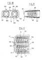
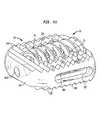
- an implant for surgery of the spineincludes an essentially hollow body which can be inserted into an intervertebral space, the body having a group of generally parallel walls defining at least two internal spaces situated side by side and exposed to the overlying and underlying vertebrae which define the intervertebral space.
- the implantadditionally has at least two anchorage reinforcement members having, on their external surface, projections for bone anchorage having a diameter greater than the overall height of the body, the said anchorage reinforcement members being adapted to be threaded into respective internal spaces of the body.
- the anchorage reinforcement membersare preferably identical.
- the hollow bodycan have different geometries.
- the upper and lower surfaces of the hollow bodyare inclined in relation to one another, with a distance between them which decreases from the proximal end towards the distal end of the body.
- the upper and lower surfaces of the hollow bodyare inclined in relation to one another, with a distance between them which decreases from a first lateral side of the body towards the opposite lateral side.
- the inventionfurthermore proposes a set of implants for forming a spinal implant intended to be inserted into an intervertebral space of the human vertebral column by being adapted to the geometry of the intervertebral space.
- This set of implantsincludes a plurality of hollow bodies, each having a pair of lateral walls defining an internal space and each able to be inserted into an intervertebral space in such a way that the internal space is exposed to the overlying and underlying vertebrae which define the intervertebral space.
- Each of the hollow bodiespreferably has a specific size and shape, at least one anchorage reinforcement member having, on its external surface, projections for bone anchorage having a diameter greater than the overall height of the bodies.
- the anchorage reinforcement memberis able to be driven in rotation in the internal space of any one of the bodies, in such a way that a specific hollow body appropriate to the particular configuration of a given intervertebral space can be chosen from among the plurality of hollow bodies.
- the specific sizes and shapes of the bodiesmay vary. Certain preferred bodies have different angles of inclination between their upper and lower surfaces. Other preferred bodies have different widths.
- the widest hollow bodiespreferably have lateral walls in which through-openings are formed which extend between the upper and lower faces of the bodies.
- the hollow bodiesmay also have different heights and different lengths.
- the hollow bodiesare preferably adapted to receive the same type of anchorage reinforcement member.
- the inventionalso proposes a method for positioning, in an intervertebral space of a human vertebral column, an implant including an essentially hollow body having a pair of lateral walls enclosing an internal space, and an anchorage reinforcement member having, on its external surface, projections for bone anchorage having a diameter greater than the overall height of the body, and adapted to be driven in rotation in the internal space of the body.
- the methodpreferably includes selecting a hollow body from a set of hollow bodies having different shapes and dimensions. The selected hollow body is preferably adapted to fit with the configuration of the intervertebral space.
- the methodalso includes filling the selected hollow body with a substance which promotes bone growth, pushing the hollow body into the intervertebral space in such a way that the internal space thereof is exposed to the overlying and underlying vertebrae which define the intervertebral space, and inserting the anchorage reinforcement member into the hollow body in such a way that the projections of the bone anchorage member anchor in the overlying and underlying vertebrae.
- the methodcan additionally include, before the step of pushing the hollow body into the intervertebral space, a step in which the through-openings are filled with a substance which promotes bone growth.
- FIG. 1is a perspective view of an implant according to a first embodiment of the invention.
- FIG. 2is a side view of the implant of FIG. 1, placed between two vertebral plates.
- FIG. 3is a front view of the implant of FIG. 1 .
- FIG. 4is a plan view of the implant of FIGS. 1 and 3.
- FIG. 5is a side view of an element of the implant of FIG. 1 .
- FIG. 6is an end view in the direction of arrow VI in FIG. 5 .
- FIG. 7is an end view in the direction of arrow VII in FIG. 5 .
- FIG. 8is a perspective view of the element of FIGS. 5 to 7 .
- FIG. 9is a perspective view of an implant according to a second embodiment of the invention.
- FIG. 10is a front view of the implant of FIG. 9 .
- FIG. 11is a plan view of the implant of FIGS. 9 and 10.
- FIG. 12is a plan view of a first element of the implant of FIGS. 9 to 11 .
- FIG. 13is a side view of a second element of the implant of FIGS. 9 to 11 .
- FIG. 14is an end view in the direction of arrow XIV in FIG. 13 .
- FIG. 15is an end view in the direction of arrow XV in FIG. 13 .
- FIG. 16is an exploded perspective view of an implant according to a third embodiment of the invention.
- FIG. 17is a side view of the implant of FIG. 16, when the implant is assembled.
- FIG. 18is a plan view in the direction of arrow XVIII in FIG. 17 .
- FIG. 19is a view in the direction of arrow XIX in FIG. 17 .
- FIG. 20is an exploded perspective view of an implant according to a fourth embodiment of the invention.
- FIG. 21is a side view of the implant of FIG. 20, when the implant is assembled.
- FIG. 22is a view in the direction of arrow XXII in FIG. 21 .
- FIG. 23is a view in the direction of arrow XXIII in FIG. 21 .
- FIG. 24is an exploded perspective view of an implant according to a fifth embodiment of the invention.
- FIG. 25is a side view of the implant of FIG. 24, when the implant is assembled.
- FIG. 26is a view in the direction of arrow XXVI in FIG. 25 .
- FIG. 27is a view in the direction of arrow XXVII in FIG. 25 .
- FIG. 28is an exploded perspective view of an implant according to a variant of the third embodiment of the invention.
- FIG. 29is a perspective view of the implant of FIG. 28 . in the assembled state.
- FIG. 30is a view of the rear of the implant of FIG. 29 .
- FIG. 31is a side view of the implant of FIG. 29 .
- FIG. 32is a plan view of the implant of FIG. 29 .
- FIG. 33is a perspective view, before assembly, of an alternative design of the third embodiment of the invention.
- FIGS. 34 to 36are three perspective views of the body of the alternative design shown in FIG. 33 .
- FIG. 37is an end view, from the distal direction, of the body of FIGS. 34-36.
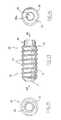
- FIG. 38is a perspective view of the anchorage reinforcement member of FIG. 33 .
- FIG. 39is a side elevational view of the anchorage reinforcement member of FIG. 33 .
- FIGS. 40 and 41show two perspective views of the implant of FIG. 33 in the assembled state.
- FIG. 42is a plan view of the implant of FIG. 40 .
- FIG. 43is a side elevational view of the implant of FIG. 40 .
- FIG. 44is an end view, from the proximal direction, of the implant of FIG. 40 .
- proximal and distalused throughout the present description correspond, respectively, to that end of the implant nearest the surgeon during a fitting operation and the end of the implant furthest from the surgeon.
- a cage-type intersomatic implantwhich is made up of two parts, namely a body 10 and an anchorage reinforcement member 20 .
- the body 10has the general shape of a ring, with an upper face 11 , a lower face 12 , an inner face 13 and an outer face 14 .
- the contour of the body 10has a circular shape truncated by a part of rectilinear contour, its width being equal, for example, to about four-thirds of its depth.
- the roughened areasare in the form of three upper ribs 11 b and three lower ribs 12 b, of triangular cross-section and of circular trajectories concentric with the circular contour part of the body.
- the bodyOpposite the rectilinear contour part, the body has a thicker wall, produced by an upper land and a lower land.
- a tapped-through orifice 18Formed in this wall part there is a tapped-through orifice 18 whose axis extends obliquely, and preferably at about 45°, relative to the vertical plane perpendicular to the plane distal wall of the implant, which vertical plane corresponds to the sagittal plane.
- this orifice 18which extends essentially horizontally, passes substantially through the center of the circular contour part, going towards the opposite region situated at the transition between the circular contour part and the rectilinear contour part.
- the implant according to the inventionadditionally includes the anchorage reinforcement member 20 adapted to reinforce the anchoring on the vertebral plateaus.
- the member 20includes a hollow cylindrical core 21 having a helical thread 22 on the outer surface thereof that is threadable into the internal thread formed in the orifice 18 .
- the member 20is closed by a solid wall 25 .
- the member 20includes a solid part 24 in which there is formed a hollow recess 24 a, for example of hexagonal cross-section, for introduction of a screwing instrument (not shown).
- the length of the member 20is such that it can be screwed into the orifice 18 of the body 10 until the outer face of its proximal solid part 24 is substantially aligned with the outer face 14 of the body 10 adjoining the orifice.
- the implantis positioned between vertebrae after the vertebrae have been distracted and a portion of the intervertebral disc has been removed.
- the body 10 of the implantwithout its member 20 , is put into the disc space, by an anterior or posterior approach.
- the internal space of the bodyis preferably first filled with bone graft material in order to ensure eventual intervertebral fusion by osteogenesis.
- the contour of the body 10is such that it is easily inscribed within the surface area of a vertebral plateau. If necessary, it is possible to offer the surgeon bodies 10 having different sizes, the particular size being selected as a function of the spinal anatomy of the patient, as will be seen in greater detail below.
- the two vertebraeare then released, and an initial immobilization of the body between the vertebral plateaus V 1 and V 2 is ensured with the aid of the ribs 11 b, 12 b.
- the member 20is then screwed into the orifice 18 with the aid of an instrument.
- the crest of the thread 22which projects slightly upwards and downwards in relation to the crest parts of the ribs 11 b, 12 b, cuts into the opposing faces of the overlying and underlying vertebral plateaus in the manner of a self-tapping screw, and thus affords a supplementary anchoring which will firmly immobilize the implant relative to these plateaus.
- the rotation of the member 20 as it penetrates the internal space of the body 10ensures that some of the bone graft material packed in the internal space will migrate through the openings 23 and into the internal space of the hollow member 20 .
- bone growthwill also be obtained through the member 20 , and this will advantageously immobilize the member 20 in terms of any rotation, particularly reverse rotation, that risks affecting the stability of the implant in the long term.
- the member 20it is also possible for the member 20 to be filled beforehand with bone graft material.
- FIGS. 9 to 15illustrate a second embodiment of the present invention.
- the body 10which has the same contour as in the case of FIGS. 1 to 8 , has a wall of essentially constant thickness over its whole periphery.
- this bodyincludes a smooth-through orifice 19 .
- a cylindrical rod 16 provided with a thread 16 aextends along the axis of the orifice 19 starting from the opposite region of the body 10 , situated essentially at the transition between its circular contour and straight contour parts.
- the member 20which has substantially the same external contour as in the case of the first embodiment, is solid, except for a central bore 28 which opens out on its rear face and in which there is formed an internal thread 28 a complementary to the thread 16 a formed on the protruding rod 16 of the body.
- the helical pitch of the thread 16 a and of the associated internal thread 28 ais chosen substantially or exactly equal to the helical pitch of the thread 22 which is still present on the outer surface of the member 20 .
- a frustoconical part 27is provided around the mouth of the bore 28 .
- the member 20has, on its front face, a screwing arrangement which preferably includes a projecting head 26 , such as a head having a hexagonal cross-section.
- the implant according to this second embodimentis used essentially in the same way as that explained above.
- the essential differencelies in the fact that the member 20 is screwed onto the rod 16 in the manner of a nut, the size of the orifice 19 being chosen so as not to form an obstacle to this screwing. In this respect it suffices to choose an orifice 19 with a diameter slightly greater than the overall diameter of the thread 22 .
- the frustoconical part 27 of the member 20makes it easier to introduce the rear end of the member into the orifice 19 prior to screwing.
- the advance of the member 20 into the body 10is such that the thread 22 here once again bites into the vertebral plateaus in the manner of a self-tapping screw.
- the upper and lower annular faces 11 and 12 of the body 10extend in planes which are slightly oblique in relation to each other, so as to adapt to the shape of the intervertebral space in question.
- the surgeonmay be provided with bodies 10 having different inclinations in order to adapt to the anatomy of the vertebrae which are to be treated.
- FIGS. 9 to 15is advantageous in that the external contour of the member 20 can be given a slightly frustoconical shape in such a way that the amount by which the thread 22 projects relative to the crests of the ribs 11 a and 11 b remains essentially constant from the front to the rear of the implant, and because the vertebral faces concerned are substantially parallel to the upper and lower faces of the body 10 , the anchoring afforded via the thread is essentially of the same magnitude from the proximal end to the distal end.
- an implantincludes a body 10 which, in horizontal section, has the general shape of a U, with a bottom 101 , or distal wall, and two essentially parallel lateral walls or branches 102 , 103 .
- the bodyincludes upper and lower U-shaped faces 104 and 104 ′, respectively, on which there are formed bone anchorage teeth 105 , 105 ′, respectively.
- the bone anchorage teethare sharp-edged teeth of triangular profile, which fulfill a role analogous to that of the ribs 11 b in the preceding embodiments.
- the upper and lower faces 104 , 104 ′converge slightly towards one another from the trailing end to the leading end 10 of the hollow body.
- the distal wall 101has a tapped bore that permits temporary fixing of an instrument (not shown) for fitting the body in the intervertebral space.
- the branches 102 , 103define a generally cylindrical internal space, for reasons explained below.
- the two lateral branches 102 , 103 of the bodyeach include a respective longitudinal through-slot 106 and 107 for permitting lateral bone growth.
- the proximal end of the body 10remote from its distal end 101 , has a generally circular opening delimited by a reentrant thread 108 provided at the proximal free ends of the two branches 102 , 103 .
- the implantincludes an anchorage reinforcement member 20 provided with a hollow core whose outer surface is slightly frustoconical, tapering from its proximal end towards its distal end.
- a continuous thread 22is formed on the outer surface of the core 21 .
- the thread 22in the form of a helically configured flat band, cooperates with the reentrant thread 10 B of the body 10 to allow the member 20 to be screwed inside the body.
- the core 21is made up of three angularly offset longitudinal branches which are separated by longitudinal empty spaces 23 .
- Each of the branchesincludes a leading edge including a cutting edge 21 a.
- the cutting edge 21 ascrapes the bone material from the overlying and underlying vertebrae. In this way, screwing in the member 20 will allow the internal space of the implant to be filled with bone chips, something which will help the graft to take and which will finally fuse the two vertebrae by means of bone growth.
- the external diameter of the thread 22is preferably very similar to the internal diameter of the body 10 , so that when the member 20 is being screwed in, it is guided inside the body.
- the member 20includes a proximal part 24 forming a bushing, the member 20 including an opening which is delimited by a plurality of bosses 24 b separated by recessed zones 24 c.
- the bosses 24 bwhich constitute the start of the branches 21 of the core, have an internal thread on their inner surface.
- the implantalso includes a generally cylindrical plug 30 having, on its outer surface, a thread 31 which is able to cooperate with the internal thread defined by the bosses 24 b.
- the rear face 32 of the plugis provided with a recessed socket 32 a for a screwing instrument.
- the body 10When inserting the implant into a disc space, the body 10 , without the member 20 , is positioned between vertebrae.
- the member 20without its plug 30 , is filled with bone graft material via its rear opening.
- the plug 30is then put into place in the rear opening to prevent the bone graft material from escaping.
- the member 20provided with its plug, is then screwed into body 10 with the aid of a screwing instrument engaged in the socket 32 a.
- the thread 22 of the member 20anchors in the opposing surfaces of the overlying and underlying vertebrae, possibly cutting off bone chips.
- the cutting edges 21 a of the three branches 21 of the core of the member 20attack the vertebrae so as to cut off chips which will complete the filling of the internal space of the member 20 .
- its frustoconical shapeensures compression of some of this bone material against the walls of the vertebrae, in order to assist the grafting.
- FIGS. 20 to 23illustrate a fourth embodiment of the invention in which the body 10 is similar to that described in FIGS. 16 to 19 .
- only branch 102 of the bodyis provided with a through-slot 106 , while the other branch 103 does not have one.
- This type of bodyis advantageously used when two implants are placed in the same intervertebral space.
- the implantsare arranged side by side in such a way that the respective slots of the two bodies are situated on the inside, in order to promote fusion with bone graft material placed in the region of the intervertebral space situated between the two implants.
- the anchorage reinforcement member 20includes a threaded plug that is substantially shorter than the body 10 in the axial direction.
- the memberhas a solid cylindrical core 21 provided with a thread 22 which is able to cooperate with the thread 103 of the body 10 .
- the rear face of the member 20has a recessed socket 24 a for a screwing instrument, and its front face 25 includes a cone with a rounded apex.
- the implant according to this embodimentis intended to be used when the body 10 is filled relatively densely with bone grafts.
- the member 20As the member 20 is being screwed into the body 10 , in addition to reinforcing the anchorage obtained with the aid of the thread 22 , the member compresses the bone grafts situated in the body 10 so as to stress these bone grafts in particular in the direction of the overlying and underlying vertebral plateaus and for improving fusion.
- FIGS. 24 to 27illustrate a fifth embodiment of the invention.
- the body 10 of the implanthas a cylindrical through-opening 101 a at the distal end 101 that is arranged on the axis of the body.
- the proximal end of the bodyhas an opening that is not threaded.
- the anchorage reinforcement member 20is a screw having a wide thread. At its front end the screw, has a shaft-like extension made up of two essentially semicylindrical axial lugs 29 a, 29 b which, at their respective free ends, have an added thickness 291 a, 291 b.
- the two lugs 29 a, 29 bhave an external diameter which is slightly smaller than the diameter of the opening 101 a of the body 10 .
- the lugsare also thinner so that their elastic deformability allows the member 20 to be snapped into the body 10 before it is fitted by the surgeon.
- the member 20is immobilized against translation, but is free in rotation.
- the member 20is guided, on the one hand, by the opening 101 a and on the other hand, by the inner faces of the two branches 102 , 103 of the body 10 .
- the member 20is delimited by two flats 201 , 201 ′, respectively, which confer upon the member a thickness which is substantially equal to the thickness of the body 10 , all along the length of the body 10 .
- the threadsform a sharp angle at the transition between the thread 22 (of square cross-section) and the flats 201 , 201 ′.
- the proximal part 24 of the member 20is provided with a recessed socket 24 a for a screwing instrument.
- the complete implantthat is to say the body 10 enclosing the member 20 which has first been clipped on, and which has been given the angular orientation in FIG. 24, is engaged by impaction into the intervertebral space. This operation is facilitated by the fact that the member 20 does not protrude beyond the limits of the body 10 .
- the member 20is turned about its axis with the aid of an appropriate instrument engaged in the socket 24 a, so that the sharp edges of the threads 22 attack the bone material of the overlying and underlying vertebral plateaus, in this way tearing off bone chips that will fill the free spaces existing between the body 10 and the member 20 , so as to contribute to the bone fusion.
- the threads 22are advantageously given a wide helical pitch so that the screwing action favors a reciprocal sliding of the threads 22 relative to the vertebral plateaus, without inducing an axial force sufficient to displace the implant in this direction.
- an implantin another preferred embodiment of the present invention, includes a wide body 10 that is designed to receive two anchorage reinforcement members, 20 a and 20 b, respectively.
- the body 10is widened and has two lateral branches 102 and 103 as well as an intermediate middle branch 109 extending between the branches 102 and 103 .
- the branches 102 and 109define a first seat for the member 20 a, while the branches 103 and 109 define a second seat for the member 20 b.
- the axes of the two seatsare mutually parallel, but being able, if appropriate, to adopt a certain inclination.
- These two seatspreferably have the same configuration as the single seat of the third embodiment, and the members 20 a and 20 b are preferably similar to the member 20 of this same embodiment.
- the body 10is provided with bone anchorage teeth 105 , 105 ′.
- the upper and lower faces 104 and 104 ′ of the body 10have a dual inclination, one corresponding to the faces coming closer together in the direction towards the distal ends of the seats, and the other corresponding to the faces coming closer together in a lateral direction (from right to left in FIG. 30 ).
- An opposite inclinationcan be obtained by turning the body 10 around.
- This dual inclinationallows the body 10 to be implanted at a slant while re-establishing the lumbar lordosis in the sagittal plane.
- the increased width of the implantensures a more stable support between the two vertebral plateaus, while the presence of two anchorage reinforcement members 20 a and 20 b reinforces the resistance to slipping relative to these plateaus.
- this variant of the inventioncan be applied to all the other implants described in the present document, with a simple adaptation of the body 10 .
- FIGS. 33 to 44a description will be given of another variant of the implant which was described with reference to FIGS. 16 to 19 .
- the outer body 10 of the implantcomprises, in the same way as before, a general U shape with two lateral branches 102 and 103 connected via a distal end wall 101 , with rounded transitions.
- the lateral branches 102 and 103have, in the lateral direction, a thickness which is substantially greater than that of the branches 102 and 103 described with reference to FIGS. 16 to 19 .
- This thicknessis preferably chosen in such a way as to give the overall width of the implant a value which is, for example, equal to about 1.5 to 2.5 times the diameter of the anchorage reinforcement member 20 .
- oblong through-openings 110 and 111are provided which extend, for example, vertically between the upper face 104 and the lower face 104 ′ of the body, in such a way that the lateral branches 102 and 103 each have a double wall. Also formed in each of these walls are generally horizontal oblong openings 106 , 106 ′, and 107 , 107 ′, respectively, which allow the internal space of the body 10 to open laterally to the outside of the body, by passing through the two double walls and the through-openings 110 , 111 , respectively.
- the upper and lower faces 104 and 104 ′ of the bodyhave a dual inclination relative to each other, in the lateral direction and from the proximal end towards the distal end.
- the anchorage reinforcement member 20has a construction similar to that which was described with reference to FIGS. 16 to 19 . It has an internal fork having two branches 21 and a helical band 22 forming a bone anchorage thread attached to the branches.
- the parts 21 and 22are preferably made in one piece.
- the thread 22is preferably a self-tapping thread, which makes it possible to screw directly into the overlying and underlying vertebral plateaus without having to form a tapping in these vertebral plateaus prior to fitting.
- the thread 22has, in its distal end region, a radial section 22 b in the form of an outwardly turned point, and this section varies progressively, for example by about a fraction of a turn, up to a rectangular radial section 22 c.
- the diameter of the thread 22increases progressively from its distal end up to the part of rectangular section, which is here of constant diameter.
- the outer faces of the branches 21are tapered, the diameter decreasing from the proximal end towards the distal end.
- the two branchesare joined at the area of a bushing 24 which is in the form of a cylindrical ring, formed preferably in one piece with the branches.
- a plug 30 having a series of flexible locking tabs 33can be mounted in this bushing 24 by being clipped in elastically from the outside.
- the tabsengage in the central opening of the bushing 24 , and the ends of which tabs, in the form of teeth 33 a, can catch onto the internal edge of the bushing 24 .
- the member 20 and its plug 30are made integral in terms of rotation by means of the fact that each pair of tabs 33 tightly encloses the start of a respective branch 21 of the fork.
- the plug 30also has a centrally arranged tapped bore 34 adapted to receive a threaded rod-shaped end of an instrument (not shown) for fitting the member 20 .
- two diametrically opposite notches 35are formed on either side of the tapped bore 34 , to permit angular indexing of the abovementioned instrument, in this case equipped with complementary arrangements, relative to the plug 30 and, thus, to the whole of the anchorage reinforcement member 20 .
- the thread 108 permitting screwing cooperation between the outer body 10 and the member 20is provided only on one of the lateral branches of the body, in the form of a reentrant flange ending in a generally rectilinear edge 108 a.
- the end of the thread 22 on the proximal sideis deformed, as indicated at 22 d.
- the deformationis formed in the direction of the adjacent thread turn, that is to say towards the distal end.
- This deformationmakes it possible to give the thread 22 an immobilizing function against reverse rotation, and thus to prevent any risk of the anchorage reinforcement member 20 coming loose from the body 10 after fitting, but before bone fusion.
- the implantis fitted in place by filling the openings 110 and 111 of the body 10 with material promoting bone growth, such as bone grafts.
- material promoting bone growthsuch as bone grafts.
- the bodyis then inserted into the intervertebral space, if necessary after distraction.
- the anchorage reinforcement member 20is filled with a material promoting bone growth, and this member 20 is then closed at its proximal end by the plug 30 being clipped in. By means of screwing, the member is engaged in the already fitted body.
- the tapered shape of the two branches 21 of the forkmakes it possible, as the member 20 advances, to compress the bone growth material and thus to ensure good contact with the overlying and underlying vertebral plateaus and with the bone growth material placed in the openings 110 and 111 , via the openings 108 and 109 .
- the implants of the present inventionare preferably made of a biocompatible material of suitable strength, such as a titanium alloy or stainless steel.
- the surgeonis preferably offered implants according to the invention in the form of a set of implants of different shapes and dimensions, making it possible for a surgeon to choose an implant, and in particular the body 10 , best suited to the anatomy of the implantation site.
- Implantscan be provided in which the bodies 10 have different heights. Because of the different body heights, the diameter of the member 20 may vary so that it works effectively with the selected body 10 . Implants can also be provided in which the bodies have different widths. Thus, in the particular case of the third embodiment, it is possible to provide a range of implants whose widths vary progressively between a minimum width (e.g. FIGS. 16 to 19 ) and a maximum width.(e.g. FIGS. 33 to 44 ), by varying the thickness, in the lateral direction, of the lateral branches 102 and 103 of the body, while at the same time maintaining the same size of internal space and also being able to use the same member 20 in all cases.
- a minimum widthe.g. FIGS. 16 to 19
- a maximum widthe.g. FIGS. 33 to 44
- These lateral branches 102 , 103preferably vary from a single wall (FIGS. 16 to 19 ) to a double wall (FIGS. 33 to 44 ) once the thickness of the branches 102 , 103 has become sufficient to allow the vertical through-openings 110 and 111 to be made.
- Implantsmay also be provided whereby the bodies have upper and lower faces of different mutual inclinations, both from the front towards the rear and also laterally, with members 20 of identical or different diameters. Implants may also be provided whereby the bodies 10 and/or the anchorage reinforcement members 20 have different lengths, and in which the anchorage reinforcement members have different anchorage projections, and in particular of greater or lesser depth and greater or lesser spacing, depending on the mechanical characteristics encountered in the vertebral plateaus, etc.
- the bone anchorage projectionscan include any structure permitting mechanical anchorage and/or bone connection with the overlying and underlying vertebral plateaus.
- thiscan be a porous coating or hydroxyapatite.
Landscapes
- Health & Medical Sciences (AREA)
- Orthopedic Medicine & Surgery (AREA)
- Engineering & Computer Science (AREA)
- Biomedical Technology (AREA)
- Neurology (AREA)
- Life Sciences & Earth Sciences (AREA)
- General Health & Medical Sciences (AREA)
- Veterinary Medicine (AREA)
- Heart & Thoracic Surgery (AREA)
- Public Health (AREA)
- Animal Behavior & Ethology (AREA)
- Surgery (AREA)
- Cardiology (AREA)
- Vascular Medicine (AREA)
- Transplantation (AREA)
- Oral & Maxillofacial Surgery (AREA)
- Nuclear Medicine, Radiotherapy & Molecular Imaging (AREA)
- Medical Informatics (AREA)
- Molecular Biology (AREA)
- Prostheses (AREA)
Abstract
Description
Claims (19)
Priority Applications (1)
| Application Number | Priority Date | Filing Date | Title |
|---|---|---|---|
| US10/172,111US6824564B2 (en) | 1997-04-25 | 2002-06-14 | Two-part intersomatic implant |
Applications Claiming Priority (6)
| Application Number | Priority Date | Filing Date | Title |
|---|---|---|---|
| FR9705137 | 1997-04-25 | ||
| FR9705137 | 1997-04-25 | ||
| FR9714150 | 1997-11-12 | ||
| FR9714150 | 1997-11-12 | ||
| US40339600A | 2000-02-15 | 2000-02-15 | |
| US10/172,111US6824564B2 (en) | 1997-04-25 | 2002-06-14 | Two-part intersomatic implant |
Related Parent Applications (2)
| Application Number | Title | Priority Date | Filing Date |
|---|---|---|---|
| PCT/FR1998/000825DivisionWO1998048738A1 (en) | 1997-04-25 | 1998-04-24 | Two-part intersomatic implant |
| US40339600ADivision | 1997-04-25 | 2000-02-15 |
Publications (2)
| Publication Number | Publication Date |
|---|---|
| US20020161445A1 US20020161445A1 (en) | 2002-10-31 |
| US6824564B2true US6824564B2 (en) | 2004-11-30 |
Family
ID=26233487
Family Applications (7)
| Application Number | Title | Priority Date | Filing Date |
|---|---|---|---|
| US10/131,741Expired - Fee RelatedUS6855168B2 (en) | 1997-04-25 | 2002-04-23 | Intersomatic implants in two parts |
| US10/172,111Expired - Fee RelatedUS6824564B2 (en) | 1997-04-25 | 2002-06-14 | Two-part intersomatic implant |
| US10/192,457Expired - Fee RelatedUS7056341B2 (en) | 1997-04-25 | 2002-07-10 | Two part intersomatic implant |
| US10/990,019Expired - Fee RelatedUS10792164B2 (en) | 1997-04-25 | 2004-11-16 | Intersomatic implants |
| US11/192,578Expired - Fee RelatedUS8840666B2 (en) | 1997-04-25 | 2005-07-29 | Two part intersomatic implant |
| US11/192,881Expired - Fee RelatedUS8449613B2 (en) | 1997-04-25 | 2005-07-29 | Two part intersomatic implant |
| US14/053,113AbandonedUS20140058520A1 (en) | 1997-04-25 | 2013-10-14 | Spinal implants |
Family Applications Before (1)
| Application Number | Title | Priority Date | Filing Date |
|---|---|---|---|
| US10/131,741Expired - Fee RelatedUS6855168B2 (en) | 1997-04-25 | 2002-04-23 | Intersomatic implants in two parts |
Family Applications After (5)
| Application Number | Title | Priority Date | Filing Date |
|---|---|---|---|
| US10/192,457Expired - Fee RelatedUS7056341B2 (en) | 1997-04-25 | 2002-07-10 | Two part intersomatic implant |
| US10/990,019Expired - Fee RelatedUS10792164B2 (en) | 1997-04-25 | 2004-11-16 | Intersomatic implants |
| US11/192,578Expired - Fee RelatedUS8840666B2 (en) | 1997-04-25 | 2005-07-29 | Two part intersomatic implant |
| US11/192,881Expired - Fee RelatedUS8449613B2 (en) | 1997-04-25 | 2005-07-29 | Two part intersomatic implant |
| US14/053,113AbandonedUS20140058520A1 (en) | 1997-04-25 | 2013-10-14 | Spinal implants |
Country Status (10)
| Country | Link |
|---|---|
| US (7) | US6855168B2 (en) |
| EP (4) | EP1769777A1 (en) |
| JP (1) | JP2001523129A (en) |
| KR (1) | KR100553297B1 (en) |
| AT (1) | ATE395016T1 (en) |
| AU (1) | AU744371B2 (en) |
| CA (1) | CA2287523C (en) |
| DE (2) | DE69839482D1 (en) |
| ES (1) | ES2150405T1 (en) |
| WO (1) | WO1998048738A1 (en) |
Cited By (111)
| Publication number | Priority date | Publication date | Assignee | Title |
|---|---|---|---|---|
| US20050071010A1 (en)* | 1997-04-25 | 2005-03-31 | Yves Crozet | Intersomatic implants in two parts |
| US20060079961A1 (en)* | 2001-01-23 | 2006-04-13 | Michelson Gary K | Implant with trailing end adapted to receive bone screws |
| USD524443S1 (en)* | 2005-11-04 | 2006-07-04 | Quantum Orthopedics, Inc. | Interbody fusion device |
| USD530423S1 (en)* | 2005-03-29 | 2006-10-17 | Nuvasive, Inc. | Intervertebral implant |
| USD533277S1 (en)* | 2005-11-04 | 2006-12-05 | Quantum Orthopedics, Inc. | Interbody fusion device |
| USD556906S1 (en)* | 2005-06-10 | 2007-12-04 | Japan Medical Materials Corporation | Dental implant |
| USD565181S1 (en)* | 2005-12-27 | 2008-03-25 | Bti, I+D, S.L. | Dental implant |
| US20080132949A1 (en)* | 2005-12-29 | 2008-06-05 | Joseph Aferzon | Apparatus and method for anterior intervertebral spinal fixation and fusion |
| US20080177307A1 (en)* | 2005-04-12 | 2008-07-24 | Moskowitz Ahmnon D | Bi-directional fixating/locking transvertebral body screw/intervertebral cage stand-alone constructs and posterior cervical and lumbar interarticulating joint stapling guns and devices for spinal fusion |
| US20080249629A1 (en)* | 2002-01-17 | 2008-10-09 | Concept Matrix Llc | Vertebral defect device |
| USD588699S1 (en) | 2005-12-27 | 2009-03-17 | Bti, I+D, S.L. | Dental implant |
| US20090125071A1 (en)* | 2007-10-23 | 2009-05-14 | Skinlo David M | Shape-changing anatomical anchor |
| USD595855S1 (en)* | 2008-11-25 | 2009-07-07 | Orthopedic Development Corporation | Bone plug |
| USD599019S1 (en) | 2008-03-07 | 2009-08-25 | Nuvasive, Inc. | Spinal fusion implant |
| US20100100140A1 (en)* | 2002-01-17 | 2010-04-22 | Concept Matrix, Llc | Insertion tool for a vertebral defect device |
| US20100249935A1 (en)* | 2009-03-30 | 2010-09-30 | Slivka Michael A | Zero Profile Spinal Fusion Cage |
| US20100305702A1 (en)* | 2002-02-02 | 2010-12-02 | Michelson Gary K | Spinal implant having deployable bone engaging projections and method for installation thereof |
| US20110029081A1 (en)* | 2000-12-14 | 2011-02-03 | Depuy Spine, Inc. | Devices and methods for facilitating controlled bone growth or repair |
| US7918891B1 (en) | 2004-03-29 | 2011-04-05 | Nuvasive Inc. | Systems and methods for spinal fusion |
| US20110137349A1 (en)* | 2005-04-12 | 2011-06-09 | Moskowitz Nathan C | Horizontal-transvertebral curvilinear nail-screws with inter-locking rigid or jointed flexible rods for spinal fusion |
| US20110295371A1 (en)* | 2005-04-12 | 2011-12-01 | Moskowitz Ahmnon D | Bi-directional fixating transvertebral body screws and posterior cervical and lumbar interarticulating joint calibrated stapling devices for spinal fusion |
| US8147521B1 (en) | 2005-07-20 | 2012-04-03 | Nuvasive, Inc. | Systems and methods for treating spinal deformities |
| US8287597B1 (en) | 2009-04-16 | 2012-10-16 | Nuvasive, Inc. | Method and apparatus for performing spine surgery |
| USD671645S1 (en) | 2007-09-18 | 2012-11-27 | Nuvasive, Inc. | Intervertebral implant |
| US8328851B2 (en) | 2005-07-28 | 2012-12-11 | Nuvasive, Inc. | Total disc replacement system and related methods |
| USD674092S1 (en) | 2008-10-15 | 2013-01-08 | Nuvasive, Inc. | Intervertebral implant |
| US8623088B1 (en) | 2005-07-15 | 2014-01-07 | Nuvasive, Inc. | Spinal fusion implant and related methods |
| US8673005B1 (en) | 2007-03-07 | 2014-03-18 | Nuvasive, Inc. | System and methods for spinal fusion |
| US20140114418A1 (en)* | 2012-10-23 | 2014-04-24 | Spinesmith Partners, L.P. | Facet fixation device |
| US8709085B2 (en) | 2003-02-06 | 2014-04-29 | DePuy Synthes Products, LLC | Intervertebral implant |
| US8747476B2 (en) | 1999-03-07 | 2014-06-10 | Nuvasive, Inc. | Spinal implant system |
| US8808377B2 (en) | 2010-01-13 | 2014-08-19 | Jcbd, Llc | Sacroiliac joint fixation system |
| US8814912B2 (en) | 2012-07-27 | 2014-08-26 | Zimmer Spine, Inc. | Bone stabilization member with bone screw retention mechanism |
| US8900310B2 (en) | 2012-04-05 | 2014-12-02 | Zimmer Spine, Inc. | Interbody spacer |
| USD721808S1 (en) | 2011-11-03 | 2015-01-27 | Nuvasive, Inc. | Intervertebral implant |
| US9005295B2 (en) | 2007-11-16 | 2015-04-14 | DePuy Synthes Products, LLC | Low profile intervertebral implant |
| US9039775B2 (en) | 2003-03-31 | 2015-05-26 | DePuy Synthes Products, Inc. | Spinal fixation plates |
| USD731063S1 (en) | 2009-10-13 | 2015-06-02 | Nuvasive, Inc. | Spinal fusion implant |
| US9101491B2 (en) | 2007-12-28 | 2015-08-11 | Nuvasive, Inc. | Spinal surgical implant and related methods |
| US9155580B2 (en) | 2011-08-25 | 2015-10-13 | Medos International Sarl | Multi-threaded cannulated bone anchors |
| USD741488S1 (en) | 2006-07-17 | 2015-10-20 | Nuvasive, Inc. | Spinal fusion implant |
| US9168152B2 (en) | 2008-02-29 | 2015-10-27 | Nuvasive, Inc. | Implants and methods for spinal fusion |
| US9192419B2 (en) | 2008-11-07 | 2015-11-24 | DePuy Synthes Products, Inc. | Zero-profile interbody spacer and coupled plate assembly |
| US9198765B1 (en) | 2011-10-31 | 2015-12-01 | Nuvasive, Inc. | Expandable spinal fusion implants and related methods |
| USD745159S1 (en) | 2013-10-10 | 2015-12-08 | Nuvasive, Inc. | Intervertebral implant |
| US9216096B2 (en) | 2010-03-16 | 2015-12-22 | Pinnacle Spine Group, Llc | Intervertebral implants and related tools |
| US9220604B2 (en) | 2010-12-21 | 2015-12-29 | DePuy Synthes Products, Inc. | Intervertebral implants, systems, and methods of use |
| USD747485S1 (en) | 2011-11-03 | 2016-01-12 | Nuvasive, Inc. | Intervertebral implant |
| US9241809B2 (en) | 2010-12-21 | 2016-01-26 | DePuy Synthes Products, Inc. | Intervertebral implants, systems, and methods of use |
| US9248028B2 (en) | 2011-09-16 | 2016-02-02 | DePuy Synthes Products, Inc. | Removable, bone-securing cover plate for intervertebral fusion cage |
| US9265548B2 (en) | 2008-10-30 | 2016-02-23 | DePuy Synthes Products, Inc. | Systems and methods for delivering bone cement to a bone anchor |
| US20160100870A1 (en)* | 2014-08-01 | 2016-04-14 | Ldr Medical | Bone Implants |
| USD754346S1 (en) | 2009-03-02 | 2016-04-19 | Nuvasive, Inc. | Spinal fusion implant |
| US9333090B2 (en) | 2010-01-13 | 2016-05-10 | Jcbd, Llc | Systems for and methods of fusing a sacroiliac joint |
| US9351845B1 (en) | 2009-04-16 | 2016-05-31 | Nuvasive, Inc. | Method and apparatus for performing spine surgery |
| US9381045B2 (en) | 2010-01-13 | 2016-07-05 | Jcbd, Llc | Sacroiliac joint implant and sacroiliac joint instrument for fusing a sacroiliac joint |
| US9380932B1 (en) | 2011-11-02 | 2016-07-05 | Pinnacle Spine Group, Llc | Retractor devices for minimally invasive access to the spine |
| US9387090B2 (en) | 2009-03-12 | 2016-07-12 | Nuvasive, Inc. | Vertebral body replacement |
| US9421109B2 (en) | 2010-01-13 | 2016-08-23 | Jcbd, Llc | Systems and methods of fusing a sacroiliac joint |
| US9445918B1 (en) | 2012-10-22 | 2016-09-20 | Nuvasive, Inc. | Expandable spinal fusion implants and related instruments and methods |
| US9510872B2 (en) | 2013-03-15 | 2016-12-06 | Jcbd, Llc | Spinal stabilization system |
| US20160374794A1 (en)* | 2006-08-16 | 2016-12-29 | Smith & Nephew, Inc. | Helicoil Interference Fixation System For Attaching a Graft Ligament to a Bone |
| US9532821B2 (en) | 2005-04-12 | 2017-01-03 | Nathan C. Moskowitz | Bi-directional fixating/locking transvertebral body screw/intervertebral cage stand-alone constructs with vertical hemi-bracket screw locking mechanism |
| US9554909B2 (en) | 2012-07-20 | 2017-01-31 | Jcbd, Llc | Orthopedic anchoring system and methods |
| US9572681B2 (en) | 2002-02-19 | 2017-02-21 | DePuy Synthes Products, Inc. | Intervertebral implant |
| US9662225B2 (en) | 2012-03-06 | 2017-05-30 | DePuy Synthes Products, Inc. | Nubbed plate |
| US9675385B2 (en) | 2005-04-12 | 2017-06-13 | Nathan C. Moskowitz | Spinous process staple with interdigitating-interlocking hemi-spacers for adjacent spinous process separation and distraction |
| US9687357B2 (en) | 2009-03-12 | 2017-06-27 | Nuvasive, Inc. | Vertebral body replacement |
| US9687354B2 (en) | 2008-03-26 | 2017-06-27 | DePuy Synthes Products, Inc. | Posterior intervertebral disc inserter and expansion techniques |
| US9693876B1 (en) | 2012-03-30 | 2017-07-04 | Ali H. MESIWALA | Spinal fusion implant and related methods |
| US9700356B2 (en) | 2013-07-30 | 2017-07-11 | Jcbd, Llc | Systems for and methods of fusing a sacroiliac joint |
| US9717539B2 (en) | 2013-07-30 | 2017-08-01 | Jcbd, Llc | Implants, systems, and methods for fusing a sacroiliac joint |
| US9744052B2 (en) | 2005-04-12 | 2017-08-29 | Nathan C. Moskowitz | Bi-directional fixating/locking transvertebral body screw/intervertebral cage stand-alone constructs |
| US9750490B2 (en) | 2002-06-26 | 2017-09-05 | Nuvasive, Inc. | Surgical access system and related methods |
| US9788961B2 (en) | 2010-01-13 | 2017-10-17 | Jcbd, Llc | Sacroiliac joint implant system |
| US9788822B2 (en) | 2003-09-25 | 2017-10-17 | Nuvasive, Inc. | Surgical access system and related methods |
| US9795371B2 (en) | 2003-01-16 | 2017-10-24 | Nuvasive, Inc. | Surgical access system and related methods |
| US9801546B2 (en) | 2014-05-27 | 2017-10-31 | Jcbd, Llc | Systems for and methods of diagnosing and treating a sacroiliac joint disorder |
| US9814601B2 (en) | 2005-04-12 | 2017-11-14 | Nathan C. Moskowitz | Bi-directional fixating/locking transvertebral body screw/intervertebral cage stand-alone constructs |
| US9820729B2 (en) | 2002-10-08 | 2017-11-21 | Nuvasive, Inc. | Surgical access system and related methods |
| US9826986B2 (en) | 2013-07-30 | 2017-11-28 | Jcbd, Llc | Systems for and methods of preparing a sacroiliac joint for fusion |
| US9848993B2 (en) | 2005-04-12 | 2017-12-26 | Nathan C. Moskowitz | Zero-profile expandable intervertebral spacer devices for distraction and spinal fusion and a universal tool for their placement and expansion |
| US9867718B2 (en) | 2014-10-22 | 2018-01-16 | DePuy Synthes Products, Inc. | Intervertebral implants, systems, and methods of use |
| US9931077B2 (en) | 2001-07-11 | 2018-04-03 | Nuvasive, Inc. | System and methods for determining nerve proximity, direction and pathology during surgery |
| US9949840B1 (en) | 2011-04-01 | 2018-04-24 | William D. Smith | Systems and methods for performing spine surgery |
| US10016225B2 (en) | 2005-04-12 | 2018-07-10 | Moskowitz Family Llc | Bi-directional fixating transvertebral body screws, zero-profile horizontal intervertebral miniplates, total intervertebral body fusion devices, and posterior motion-calibrating interarticulating joint stapling device for spinal fusion |
| US10070970B2 (en) | 2013-03-14 | 2018-09-11 | Pinnacle Spine Group, Llc | Interbody implants and graft delivery systems |
| US10182921B2 (en) | 2012-11-09 | 2019-01-22 | DePuy Synthes Products, Inc. | Interbody device with opening to allow packing graft and other biologics |
| US10206787B2 (en) | 2006-12-22 | 2019-02-19 | Medos International Sarl | Composite vertebral spacers and instrument |
| US20190090922A1 (en)* | 2017-09-22 | 2019-03-28 | Howmedica Osteonics Corp. | Distal Radius Wedge Screw |
| US10245087B2 (en) | 2013-03-15 | 2019-04-02 | Jcbd, Llc | Systems and methods for fusing a sacroiliac joint and anchoring an orthopedic appliance |
| US10335289B2 (en) | 2010-09-23 | 2019-07-02 | DePuy Synthes Products, Inc. | Stand alone intervertebral fusion device |
| US10369015B2 (en) | 2010-09-23 | 2019-08-06 | DePuy Synthes Products, Inc. | Implant inserter having a laterally-extending dovetail engagement feature |
| USD858769S1 (en) | 2014-11-20 | 2019-09-03 | Nuvasive, Inc. | Intervertebral implant |
| US10500062B2 (en) | 2009-12-10 | 2019-12-10 | DePuy Synthes Products, Inc. | Bellows-like expandable interbody fusion cage |
| US10507120B2 (en) | 2001-09-25 | 2019-12-17 | Nuvasive, Inc. | Systems and methods for performing surgical procedures and assessments |
| US10512548B2 (en) | 2006-02-27 | 2019-12-24 | DePuy Synthes Products, Inc. | Intervertebral implant with fixation geometry |
| US10603055B2 (en) | 2017-09-15 | 2020-03-31 | Jcbd, Llc | Systems for and methods of preparing and fusing a sacroiliac joint |
| US10653308B2 (en) | 2003-10-17 | 2020-05-19 | Nuvasive, Inc. | Surgical access system and related methods |
| US10772738B2 (en) | 2017-07-18 | 2020-09-15 | Blue Sky Technologies, LLC | Joint arthrodesis system |
| US10940016B2 (en) | 2017-07-05 | 2021-03-09 | Medos International Sarl | Expandable intervertebral fusion cage |
| US11419736B2 (en) | 2017-07-18 | 2022-08-23 | Blue Sky Technologies, LLC | Joint implant |
| US11497619B2 (en) | 2013-03-07 | 2022-11-15 | DePuy Synthes Products, Inc. | Intervertebral implant |
| US11529241B2 (en) | 2010-09-23 | 2022-12-20 | DePuy Synthes Products, Inc. | Fusion cage with in-line single piece fixation |
| US20230277332A1 (en)* | 2021-10-12 | 2023-09-07 | Randall F. Lee | System and method for a medical implant with integrated propulsors |
| US11903849B2 (en) | 2005-04-12 | 2024-02-20 | Moskowitz Family Llc | Intervertebral implant and tool assembly |
| US12023255B2 (en) | 2008-04-05 | 2024-07-02 | DePuy Synthes Products, Inc. | Expandable inter vertebral implant |
| US12023258B2 (en) | 2021-04-06 | 2024-07-02 | Medos International Sarl | Expandable intervertebral fusion cage |
| US12036131B2 (en) | 2019-05-24 | 2024-07-16 | Blue Sky Technologies, LLC | Joint implant |
| US12433757B2 (en) | 2016-06-28 | 2025-10-07 | Eit Emerging Implant Technologies Gmbh | Expandable, angularly adjustable and articulating intervertebral cages |
| US12440346B2 (en) | 2023-03-31 | 2025-10-14 | DePuy Synthes Products, Inc. | Expandable intervertebral implant |
Families Citing this family (152)
| Publication number | Priority date | Publication date | Assignee | Title |
|---|---|---|---|---|
| DE19753685C1 (en)* | 1997-12-03 | 1999-09-16 | Biedermann Motech Gmbh | Intravertebral surgical implant |
| DE19903764B4 (en)* | 1998-01-23 | 2005-03-31 | Aesculap Ag & Co. Kg | Intervertebral implant |
| US6224631B1 (en) | 1998-03-20 | 2001-05-01 | Sulzer Spine-Tech Inc. | Intervertebral implant with reduced contact area and method |
| FR2782632B1 (en) | 1998-08-28 | 2000-12-29 | Materiel Orthopedique En Abreg | EXPANSIBLE INTERSOMATIC FUSION CAGE |
| BR9805340B1 (en) | 1998-12-14 | 2009-01-13 | variable expansion insert for spinal stabilization. | |
| US5989256A (en)* | 1999-01-19 | 1999-11-23 | Spineology, Inc. | Bone fixation cable ferrule |
| US6241770B1 (en)* | 1999-03-05 | 2001-06-05 | Gary K. Michelson | Interbody spinal fusion implant having an anatomically conformed trailing end |
| EP1043002A3 (en)* | 1999-04-07 | 2001-11-28 | Christos Kalaitzis | Intervertebral disc replacement prosthesis |
| EP1198208B1 (en) | 1999-05-05 | 2013-07-10 | Warsaw Orthopedic, Inc. | Nested interbody spinal fusion implants |
| FR2795945B1 (en) | 1999-07-09 | 2001-10-26 | Scient X | ANATOMICAL INTERSOMATIC IMPLANT AND GRIPPER FOR SUCH AN IMPLANT |
| FR2799639B1 (en)* | 1999-10-18 | 2002-07-19 | Dimso Sa | TOOTHED FACED INTERVERTEBRAL DISC PROSTHESIS |
| US6530929B1 (en) | 1999-10-20 | 2003-03-11 | Sdgi Holdings, Inc. | Instruments for stabilization of bony structures |
| US20010032017A1 (en) | 1999-12-30 | 2001-10-18 | Alfaro Arthur A. | Intervertebral implants |
| TW431172U (en) | 2000-02-02 | 2001-04-21 | Lin Jr Yi | Device with side plate for fastening and restoring spine |
| WO2001066048A1 (en)* | 2000-03-09 | 2001-09-13 | Osteotech, Inc. | Anterior lumbar spacer |
| US7462195B1 (en) | 2000-04-19 | 2008-12-09 | Warsaw Orthopedic, Inc. | Artificial lumbar interbody spinal implant having an asymmetrical leading end |
| US6350283B1 (en) | 2000-04-19 | 2002-02-26 | Gary K. Michelson | Bone hemi-lumbar interbody spinal implant having an asymmetrical leading end and method of installation thereof |
| US7018416B2 (en) | 2000-07-06 | 2006-03-28 | Zimmer Spine, Inc. | Bone implants and methods |
| US6626905B1 (en) | 2000-08-02 | 2003-09-30 | Sulzer Spine-Tech Inc. | Posterior oblique lumbar arthrodesis |
| US20030120274A1 (en) | 2000-10-20 | 2003-06-26 | Morris John W. | Implant retaining device |
| GR20000100414A (en) | 2000-11-22 | 2002-09-26 | Χρηστος Καλαιτζης | Implant for the arthrodesis of the intrervertebral margin by anterior or posterior approach |
| US6890355B2 (en) | 2001-04-02 | 2005-05-10 | Gary K. Michelson | Artificial contoured spinal fusion implants made of a material other than bone |
| US6989031B2 (en) | 2001-04-02 | 2006-01-24 | Sdgi Holdings, Inc. | Hemi-interbody spinal implant manufactured from a major long bone ring or a bone composite |
| US6558424B2 (en)* | 2001-06-28 | 2003-05-06 | Depuy Acromed | Modular anatomic fusion device |
| FR2829689B1 (en)* | 2001-09-14 | 2004-06-25 | Frederic Fortin | NUCLEUS PROSTHESIS AND ITS INSERTION DEVICE AND ITS POSITIONING METHOD |
| US6855167B2 (en) | 2001-12-05 | 2005-02-15 | Osteotech, Inc. | Spinal intervertebral implant, interconnections for such implant and processes for making |
| FR2835739B1 (en)* | 2002-02-11 | 2004-05-14 | Spinevision | SYSTEM FOR FIXING A WORKPIECE ON A BONE BODY |
| US7309358B2 (en)* | 2002-03-21 | 2007-12-18 | Warsaw Orthopedic, Inc. | Vertebral body and disc space replacement devices |
| US6758862B2 (en)* | 2002-03-21 | 2004-07-06 | Sdgi Holdings, Inc. | Vertebral body and disc space replacement devices |
| US8388684B2 (en) | 2002-05-23 | 2013-03-05 | Pioneer Signal Technology, Inc. | Artificial disc device |
| US7001433B2 (en) | 2002-05-23 | 2006-02-21 | Pioneer Laboratories, Inc. | Artificial intervertebral disc device |
| WO2003105673A2 (en)* | 2002-06-17 | 2003-12-24 | Trimedyne, Inc. | Devices and methods for minimally invasive treatment of degenerated spinal discs |
| US7018414B2 (en)* | 2002-07-30 | 2006-03-28 | Brau Salvador A | Support device for vertebral fusion |
| US20060173543A1 (en)* | 2002-07-30 | 2006-08-03 | Brau Salvador A | Support device for vertebral fusion |
| US7967851B2 (en) | 2003-05-08 | 2011-06-28 | Bickley Barry T | Method and apparatus for securing an object to bone |
| WO2004100809A1 (en)* | 2003-05-08 | 2004-11-25 | Bickley Barry T | Fixation augmentation device and related techniques |
| US8506605B2 (en) | 2002-09-18 | 2013-08-13 | Simplicity Orthopedics, Inc. | Method and apparatus for securing an object to bone and/or for stabilizing bone |
| DE10246177A1 (en) | 2002-10-02 | 2004-04-22 | Biedermann Motech Gmbh | Anchor element consists of screw with head, bone-thread section on shank and holder joining rod-shaped part to screw. with cavities in wall, and thread-free end of shank |
| DE10260222B4 (en)* | 2002-12-20 | 2008-01-03 | Biedermann Motech Gmbh | Tubular element for an implant and implant to be used in spine or bone surgery with such an element |
| US7828849B2 (en) | 2003-02-03 | 2010-11-09 | Warsaw Orthopedic, Inc. | Expanding interbody implant and articulating inserter and method |
| WO2004084742A1 (en)* | 2003-03-24 | 2004-10-07 | Theken Surgical Llc | Spinal implant adjustment device |
| US8012212B2 (en)* | 2003-04-07 | 2011-09-06 | Nuvasive, Inc. | Cervical intervertebral disk prosthesis |
| BRPI0409091A (en)* | 2003-04-07 | 2006-04-11 | Cervitech Inc | intervertebral joint prosthesis for the cervical spine |
| DE202004021289U1 (en)* | 2003-05-14 | 2007-06-06 | Kraus, Kilian | Height-adjustable implant for insertion between vertebral bodies and handling tool |
| DE10357926B3 (en) | 2003-12-11 | 2005-09-01 | Deltacor Gmbh | Length adjustable spinal implant |
| US8333985B2 (en) | 2004-01-27 | 2012-12-18 | Warsaw Orthopedic, Inc. | Non-glycerol stabilized bone graft |
| US7544208B1 (en) | 2004-05-03 | 2009-06-09 | Theken Spine, Llc | Adjustable corpectomy apparatus |
| US7678148B2 (en)* | 2004-07-23 | 2010-03-16 | Warsaw Orthopedic, Inc. | Expandable spinal implant having interlocking geometry for structural support |
| US8262713B2 (en) | 2005-09-26 | 2012-09-11 | Depuy Spine, Inc. | Red light implant for treating osteoporosis |
| US7465313B2 (en)* | 2005-09-26 | 2008-12-16 | Depuy Spine, Inc. | Red light implant for treating degenerative disc disease |
| US7935148B2 (en)* | 2006-01-09 | 2011-05-03 | Warsaw Orthopedic, Inc. | Adjustable insertion device for a vertebral implant |
| DE102006010116A1 (en)* | 2006-02-27 | 2007-08-30 | Karl Storz Gmbh & Co.Kg | Anchor element for knot-free fixation of tissue to a bone |
| US8066714B2 (en)* | 2006-03-17 | 2011-11-29 | Warsaw Orthopedic Inc. | Instrumentation for distraction and insertion of implants in a spinal disc space |
| US7615077B2 (en)* | 2006-03-31 | 2009-11-10 | Warsaw Orthopedic, Inc. | Intervertebral implants with radial teeth and methods of use |
| US7850736B2 (en)* | 2006-04-13 | 2010-12-14 | Warsaw Orthopedic, Inc. | Vertebral fusion implants and methods of use |
| US8353962B2 (en)* | 2006-04-28 | 2013-01-15 | Concept Matrix, Llc | Dual composition vertebral defect device |
| US20080154314A1 (en)* | 2006-08-16 | 2008-06-26 | Mcdevitt Dennis M | Composite interference screw for attaching a graft ligament to a bone, and other apparatus for making attachments to bone |
| WO2008034140A2 (en)* | 2006-09-15 | 2008-03-20 | Pioneer Surgical Technology, Inc. | Systems and methods for sizing, inserting and securing an implant intervertebral space |
| US8715350B2 (en)* | 2006-09-15 | 2014-05-06 | Pioneer Surgical Technology, Inc. | Systems and methods for securing an implant in intervertebral space |
| WO2008034135A2 (en) | 2006-09-15 | 2008-03-20 | Pioneer Surgical Technology, Inc. | Joint arthroplasty devices having articulating members |
| US8377133B2 (en)* | 2006-09-15 | 2013-02-19 | Pioneer Surgical Technology, Inc. | Systems and methods for sizing, inserting and securing an implant in intervertebral space |
| US8372157B2 (en) | 2007-02-12 | 2013-02-12 | Warsaw Orthopedic, Inc. | Joint revision implant |
| US8133261B2 (en)* | 2007-02-26 | 2012-03-13 | Depuy Spine, Inc. | Intra-facet fixation device and method of use |
| KR101453961B1 (en) | 2007-03-13 | 2014-10-21 | 신세스 게엠바하 | adjustable intervertebral implant |
| US8043334B2 (en)* | 2007-04-13 | 2011-10-25 | Depuy Spine, Inc. | Articulating facet fusion screw |
| US8894685B2 (en) | 2007-04-13 | 2014-11-25 | DePuy Synthes Products, LLC | Facet fixation and fusion screw and washer assembly and method of use |
| US8197513B2 (en) | 2007-04-13 | 2012-06-12 | Depuy Spine, Inc. | Facet fixation and fusion wedge and method of use |
| US8273127B2 (en)* | 2007-06-06 | 2012-09-25 | Spinesmith Partners, L.P. | Interbody fusion device and associated methods |
| US8231676B2 (en)* | 2007-09-17 | 2012-07-31 | Pioneer Surgical Technology, Inc. | Motion preserving artificial intervertebral disc device |
| WO2009076526A1 (en) | 2007-12-13 | 2009-06-18 | Smith & Nephew, Inc. | Anchoring system |
| CA2735001A1 (en)* | 2008-09-02 | 2010-03-11 | Synthes Usa, Llc | Implant with spiral anchor |
| JP5602739B2 (en) | 2008-09-02 | 2014-10-08 | ジンテス ゲゼルシャフト ミット ベシュレンクテル ハフツング | Intervertebral implant having blades for connection to adjacent vertebral bodies |
| BRPI0822953A2 (en) | 2008-09-04 | 2015-06-23 | Synthes Gmbh | Adjustable intervertebral implant |
| US8814937B2 (en) | 2008-09-18 | 2014-08-26 | Peter L. Mayer | Intervertebral disc prosthesis, method for assembling, method for implanting prosthesis, and method for explanting |
| US8187333B2 (en)* | 2008-09-18 | 2012-05-29 | Mayer Peter L | Intervertebral disc prosthesis and method for implanting and explanting |
| US9204886B2 (en)* | 2009-05-15 | 2015-12-08 | Zimmer, Inc. | Threaded, flexible implant and method for threading a curved hole |
| USD629104S1 (en)* | 2009-06-05 | 2010-12-14 | Globus Medical, Inc. | Lordotic lateral fusion implant |
| USD625820S1 (en)* | 2009-06-05 | 2010-10-19 | Globus Medical, Inc. | Lateral fusion implant |
| US8617244B2 (en)* | 2009-06-17 | 2013-12-31 | DePuy Synthes Products, LLC | Intervertebral implant |
| US20110106179A1 (en)* | 2009-10-30 | 2011-05-05 | Warsaw Orthopedic, Inc. | Set Screw Having Variable Pitch Thread for Use With Spinal Implant Systems |
| WO2011098634A1 (en)* | 2010-02-12 | 2011-08-18 | Alonso Abajo Antonio Magin | Device for the treatment of spine pathologies |
| US9775702B2 (en) | 2010-03-10 | 2017-10-03 | Smith & Nephew, Inc. | Composite interference screws and drivers |
| US9308080B2 (en) | 2010-03-10 | 2016-04-12 | Smith & Nephew Inc. | Composite interference screws and drivers |
| US8979865B2 (en) | 2010-03-10 | 2015-03-17 | Smith & Nephew, Inc. | Composite interference screws and drivers |
| US9579188B2 (en) | 2010-03-10 | 2017-02-28 | Smith & Nephew, Inc. | Anchor having a controlled driver orientation |
| FR2960419B1 (en)* | 2010-05-25 | 2013-03-15 | Prosteel | SYSTEM FOR REALIZING ARTHRODESIS BETWEEN TWO VERTEBRATES |
| US8377139B2 (en) | 2010-06-17 | 2013-02-19 | Aesculap Implant Systems, Llc | Standalone interbody fusion device with locking and release mechanism |
| US9089372B2 (en) | 2010-07-12 | 2015-07-28 | DePuy Synthes Products, Inc. | Pedicular facet fusion screw with plate |
| EP2455014B1 (en)* | 2010-11-17 | 2015-08-12 | Hyprevention | Implantable device for preventive or interventive treatment of femur fractures, associated ancillary device |
| US9579214B1 (en) | 2011-03-01 | 2017-02-28 | John W. McClellan | Peripheral vertebral body spacer implant and insertion tool |
| MX344606B (en) | 2011-03-11 | 2016-12-20 | Smith & Nephew Inc | Trephine. |
| WO2012148838A1 (en) | 2011-04-26 | 2012-11-01 | Alphatec Spine, Inc. | Stand alone interbody fixation system |
| US20120283836A1 (en)* | 2011-05-06 | 2012-11-08 | The 175Th Hospital Of Pla | Interbody fusion device |
| PL218347B1 (en) | 2011-05-12 | 2014-11-28 | Lfc Spółka Z Ograniczoną Odpowiedzialnością | Intervertebral implant for positioning of adjacent vertebrae |
| AU2012267924B2 (en) | 2011-06-07 | 2016-08-11 | Smith & Nephew, Inc. | Surgical anchor delivery system |
| US9237957B2 (en)* | 2011-09-16 | 2016-01-19 | Globus Medical, Inc. | Low profile plate |
| US9539102B2 (en) | 2011-09-16 | 2017-01-10 | Globus Medical, Inc. | Multi-piece intervertebral implants |
| US9204975B2 (en) | 2011-09-16 | 2015-12-08 | Globus Medical, Inc. | Multi-piece intervertebral implants |
| US8961606B2 (en)* | 2011-09-16 | 2015-02-24 | Globus Medical, Inc. | Multi-piece intervertebral implants |
| US9539109B2 (en) | 2011-09-16 | 2017-01-10 | Globus Medical, Inc. | Low profile plate |
| US9149365B2 (en)* | 2013-03-05 | 2015-10-06 | Globus Medical, Inc. | Low profile plate |
| US9398960B2 (en) | 2011-09-16 | 2016-07-26 | Globus Medical, Inc. | Multi-piece intervertebral implants |
| KR101326054B1 (en)* | 2011-09-23 | 2013-11-07 | 서울대학교산학협력단 | Spinal implant |
| KR101225006B1 (en)* | 2011-09-28 | 2013-01-22 | 주식회사 코렌텍 | Porous cage for intervertebral body fusion and the method preparing thereof |
| US20140058446A1 (en)* | 2011-09-28 | 2014-02-27 | Avi Bernstein | Spinal implant system |
| FR2981262B1 (en)* | 2011-10-14 | 2014-09-19 | Pierre Roussouly | INTERSOMATIC IMPLANT |
| EP2596758A1 (en)* | 2011-11-24 | 2013-05-29 | Sysorb GmbH | Bone screw |
| US9198769B2 (en) | 2011-12-23 | 2015-12-01 | Pioneer Surgical Technology, Inc. | Bone anchor assembly, bone plate system, and method |
| US9750616B2 (en) | 2012-02-17 | 2017-09-05 | Spinal Elements, Inc. | Interbody fusion device |
| US9393126B2 (en) | 2012-04-20 | 2016-07-19 | Peter L. Mayer | Bilaterally placed disc prosthesis for spinal implant and method of bilateral placement |
| US9364339B2 (en) | 2012-04-30 | 2016-06-14 | Peter L. Mayer | Unilaterally placed expansile spinal prosthesis |
| US9387021B2 (en)* | 2012-08-20 | 2016-07-12 | Ebi, Llc | Implant with semi-enclosed screws |
| WO2014085870A1 (en) | 2012-12-08 | 2014-06-12 | Kevin Seex | Surgical tool |
| KR20150128684A (en)* | 2013-03-06 | 2015-11-18 | 스미스 앤드 네퓨, 인크. | Composite interference screws and drivers |
| CN105188562B (en) | 2013-03-06 | 2019-02-26 | 史密夫和内修有限公司 | Micro Anchor |
| US9155531B2 (en) | 2013-03-15 | 2015-10-13 | Smith & Nephew, Inc. | Miniaturized dual drive open architecture suture anchor |
| US9526488B2 (en) | 2013-03-15 | 2016-12-27 | Smith & Nephew, Inc. | Fenestrated locking suture anchor assembly |
| WO2014169058A1 (en) | 2013-04-09 | 2014-10-16 | Smith & Nephew, Inc | Open-architecture interference screw |
| FR3005569B1 (en)* | 2013-05-16 | 2021-09-03 | Ldr Medical | VERTEBRAL IMPLANT, VERTEBRAL IMPLANT FIXATION DEVICE AND IMPLANTATION INSTRUMENTATION |
| US8932358B1 (en)* | 2013-10-07 | 2015-01-13 | Daniel Nehls | Anterior intervertebral spacer and integrated plate assembly and methods of use |
| US9364341B2 (en)* | 2014-01-09 | 2016-06-14 | Warsaw Orthopedic, Inc. | Spinal implant system and method |
| US10478313B1 (en) | 2014-01-10 | 2019-11-19 | Nuvasive, Inc. | Spinal fusion implant and related methods |
| KR101647453B1 (en)* | 2014-12-03 | 2016-08-10 | 주식회사 메드릭스 | Band fixing spacer device for spinous process |
| US20160213405A1 (en)* | 2015-01-27 | 2016-07-28 | K2M, Inc. | Vertebral plate systems and methods of use |
| US10028841B2 (en) | 2015-01-27 | 2018-07-24 | K2M, Inc. | Interbody spacer |
| US10342678B2 (en) | 2015-02-02 | 2019-07-09 | Spinal Elements, Inc. | Interbody implant inserter |
| US10117752B2 (en)* | 2015-02-26 | 2018-11-06 | Uncinate Joint, Llc | Uncinate joint stabilizers and associated systems and methods |
| US10449051B2 (en) | 2015-04-29 | 2019-10-22 | Institute for Musculoskeletal Science and Education, Ltd. | Implant with curved bone contacting elements |
| JP6768001B2 (en) | 2015-04-29 | 2020-10-14 | インスティテュート フォー マスキュロスケレタル サイエンス アンド エジュケイション,リミテッド | Coiled implants and systems and how to make them |
| US10492921B2 (en) | 2015-04-29 | 2019-12-03 | Institute for Musculoskeletal Science and Education, Ltd. | Implant with arched bone contacting elements |
| US10166116B2 (en) | 2015-12-02 | 2019-01-01 | Brian Patrick Janowski | Helical lock spacer, instruments and methods |
| US10034699B2 (en) | 2016-01-14 | 2018-07-31 | DePuy Synthes Products, Inc. | Stand-alone fusion implant secured by in-line fixation |
| CN105662569A (en)* | 2016-02-22 | 2016-06-15 | 运怡(北京)医疗器械有限公司 | Combined interface nail |
| US11033394B2 (en) | 2016-10-25 | 2021-06-15 | Institute for Musculoskeletal Science and Education, Ltd. | Implant with multi-layer bone interfacing lattice |
| US10478312B2 (en)* | 2016-10-25 | 2019-11-19 | Institute for Musculoskeletal Science and Education, Ltd. | Implant with protected fusion zones |
| US10111755B2 (en) | 2017-02-24 | 2018-10-30 | Warsaw, Orthopedic, Inc. | Expanding interbody implant and articulating inserter and methods of use |
| US10667924B2 (en)* | 2017-03-13 | 2020-06-02 | Institute for Musculoskeletal Science and Education, Ltd. | Corpectomy implant |
| US10512549B2 (en) | 2017-03-13 | 2019-12-24 | Institute for Musculoskeletal Science and Education, Ltd. | Implant with structural members arranged around a ring |
| US10470894B2 (en) | 2017-04-06 | 2019-11-12 | Warsaw Orthopedic, Inc. | Expanding interbody implant and articulating inserter and methods of use |
| WO2019051260A1 (en) | 2017-09-08 | 2019-03-14 | Pioneer Surgical Technology, Inc. | Intervertebral implants, instruments, and methods |
| USD907771S1 (en) | 2017-10-09 | 2021-01-12 | Pioneer Surgical Technology, Inc. | Intervertebral implant |
| US10940015B2 (en) | 2017-11-21 | 2021-03-09 | Institute for Musculoskeletal Science and Education, Ltd. | Implant with improved flow characteristics |
| US10744001B2 (en) | 2017-11-21 | 2020-08-18 | Institute for Musculoskeletal Science and Education, Ltd. | Implant with improved bone contact |
| JP6979051B2 (en)* | 2018-08-27 | 2021-12-08 | グローバス メディカル インコーポレイティッド | Screw implants for bone fixation |
| US11141262B2 (en)* | 2018-12-21 | 2021-10-12 | Industrial Technology Research Institute | Bone implant |
| EP3669824B1 (en)* | 2018-12-21 | 2025-09-10 | Industrial Technology Research Institute | Bone implant |
| JP2022531020A (en) | 2019-05-07 | 2022-07-05 | スパイナル・エレメンツ・インコーポレーテッド | Neck plate and inserter |
| US11246631B2 (en) | 2020-02-12 | 2022-02-15 | Blue Sky Technologies, LLC | Surgical fastener |
| US11883302B2 (en)* | 2021-11-22 | 2024-01-30 | Warsaw Orthopedic, Inc. | Spinal implant having a compressible insert |
| US20250025310A1 (en)* | 2021-12-10 | 2025-01-23 | Surgentec, Llc | Joint stabilization system |
| FR3132625B1 (en) | 2022-02-17 | 2024-04-12 | Sc Medica | IMPLANT DEVICE FOR PERFORMING A POSTERIOR SPINAL ARTHRODESIS AT THE LEVEL OF A FACET JOINT, AND SYSTEM COMPRISING SAID IMPLANT AND ITS PLACEMENT TOOL. |
| CN117323069A (en)* | 2023-09-28 | 2024-01-02 | 中国人民解放军南部战区总医院 | Screw-in side block fusion device and matched instrument thereof |
Citations (26)
| Publication number | Priority date | Publication date | Assignee | Title |
|---|---|---|---|---|
| US2677369A (en) | 1952-03-26 | 1954-05-04 | Fred L Knowles | Apparatus for treatment of the spinal column |
| US4834757A (en) | 1987-01-22 | 1989-05-30 | Brantigan John W | Prosthetic implant |
| WO1990011740A1 (en) | 1989-04-08 | 1990-10-18 | Robert Bosch Gmbh | Artificial spinal disc |
| FR2703580A1 (en) | 1993-03-03 | 1994-10-14 | Robert Gilles | Intersomatic cervical cage |
| FR2710519A1 (en) | 1993-09-29 | 1995-04-07 | Robine Dominique | Intervertebral lumbar cage (CH) |
| EP0664994A1 (en) | 1994-01-26 | 1995-08-02 | BIOMAT(S.a.r.l.) | Interbody vertebral cage |
| DE4409392A1 (en) | 1994-03-18 | 1995-09-21 | Biedermann Motech Gmbh | Adjustable vertebral body |
| US5458638A (en) | 1989-07-06 | 1995-10-17 | Spine-Tech, Inc. | Non-threaded spinal implant |
| DE29519419U1 (en) | 1994-12-09 | 1996-02-29 | Armbrust, Helmut, 66679 Losheim | Handle with leash for leading pets |
| FR2724312A1 (en) | 1995-04-21 | 1996-03-15 | Alby Albert | Inter-somatic dorsal-lumber spacer |
| WO1996014809A1 (en) | 1994-11-16 | 1996-05-23 | Atlas Implants | Implant for the fusion of two adjacent bony bodies, particularly two consecutive vertebrae |
| DE29519418U1 (en) | 1995-12-07 | 1996-05-23 | Diehl, Klaus, Prof. Dr., 66123 Saarbrücken | Self-tapping banjo bolt |
| FR2727003A1 (en) | 1994-11-18 | 1996-05-24 | Euros Sa | Lumbar-sacral vertebrae anterior stabiliser |
| FR2727004A1 (en) | 1994-11-18 | 1996-05-24 | Euros Sa | Lumbar and lumbar-sacral posterior stabiliser |
| EP0716840A2 (en) | 1994-12-12 | 1996-06-19 | Surgical Dynamics, Inc. | Conically-shaped fusion cage and method of implantation |
| WO1996027339A1 (en) | 1995-03-08 | 1996-09-12 | Advanced Microbotics Corporation | Spinal disc implant |
| DE29612269U1 (en) | 1996-07-15 | 1996-09-12 | Aesculap Ag, 78532 Tuttlingen | Vertebral fusion implant |
| EP0732093A2 (en) | 1995-02-17 | 1996-09-18 | Sofamor Danek Group, Inc. | Interbody spinal fusion implants |
| WO1996040016A2 (en) | 1994-03-18 | 1996-12-19 | Madhavan Pisharodi | Intervertebral disk stabilizer and instrument for reduction of spondylolisthesis |
| US5609635A (en) | 1988-06-28 | 1997-03-11 | Michelson; Gary K. | Lordotic interbody spinal fusion implants |
| WO1997015246A1 (en) | 1995-10-20 | 1997-05-01 | Synthes Ag Chur | Intervertebral implant with cage and rotating element |
| US5776199A (en) | 1988-06-28 | 1998-07-07 | Sofamor Danek Properties | Artificial spinal fusion implants |
| US5800550A (en) | 1996-03-13 | 1998-09-01 | Sertich; Mario M. | Interbody fusion cage |
| US5860973A (en) | 1995-02-27 | 1999-01-19 | Michelson; Gary Karlin | Translateral spinal implant |
| US5865845A (en) | 1996-03-05 | 1999-02-02 | Thalgott; John S. | Prosthetic intervertebral disc |
| US6129763A (en) | 1996-09-13 | 2000-10-10 | Chauvin; Jean-Luc | Expandable osteosynthesis cage |
Family Cites Families (35)
| Publication number | Priority date | Publication date | Assignee | Title |
|---|---|---|---|---|
| US1282538A (en)* | 1917-03-07 | 1918-10-22 | Harry Cadwallader Jr | Machine-bolt. |
| GB8620937D0 (en)* | 1986-08-29 | 1986-10-08 | Shepperd J A N | Spinal implant |
| US4936851A (en)* | 1988-08-26 | 1990-06-26 | Colin Electronics Co., Ltd. | Analytic bone implant |
| FR2659225B1 (en)* | 1990-03-08 | 1995-09-08 | Sofamor | TRANSVERSE FIXING DEVICE FOR PROVIDING A RIGID CROSS-LINK BETWEEN TWO RODS OF A SPINAL OSTEOSYNTHESIS SYSTEM. |
| DE4012622C1 (en)* | 1990-04-20 | 1991-07-18 | Eska Medical Luebeck Medizintechnik Gmbh & Co, 2400 Luebeck, De | Two-part metal vertebra implant - has parts locked by two toothed racks, pre-stressed by elastic cushion between both implant parts |
| GB9014817D0 (en)* | 1990-07-04 | 1990-08-22 | Mehdian Seyed M H | Improvements in or relating to apparatus for use in the treatment of spinal disorders |
| US5192327A (en)* | 1991-03-22 | 1993-03-09 | Brantigan John W | Surgical prosthetic implant for vertebrae |
| US5306307A (en)* | 1991-07-22 | 1994-04-26 | Calcitek, Inc. | Spinal disk implant |
| US5258031A (en)* | 1992-01-06 | 1993-11-02 | Danek Medical | Intervertebral disk arthroplasty |
| US5766251A (en)* | 1992-03-13 | 1998-06-16 | Tomihisa Koshino | Wedge-shaped spacer for correction of deformed extremities |
| FR2703850B1 (en) | 1993-04-09 | 1995-06-30 | Sgs Thomson Microelectronics | PROTECTION OF AN AUTOMOTIVE THREE-PHASE ALTERNATOR. |
| FR2708461B1 (en)* | 1993-08-06 | 1995-09-29 | Advanced Technical Fabrication | Interbody implant for spine. |
| US5885845A (en)* | 1993-12-22 | 1999-03-23 | Nippon Sanso Corporation | Method for detecting inorganic hydrides, inorganic halides and organometallic compounds in a gas using copper hydroxide |
| FR2717068B1 (en)* | 1994-03-14 | 1996-04-26 | Biomat | Vertebral interbody fusion cage. |
| FR2718955B1 (en)* | 1994-04-25 | 1996-08-02 | Soprane Sa | Inter-somatic cage for lumbar intervertebral arthrodesis of a spine. |
| DE9407806U1 (en)* | 1994-05-11 | 1994-07-14 | Aesculap AG & Co. KG, 78532 Tuttlingen | Intervertebral implant |
| JP3509103B2 (en) | 1994-05-23 | 2004-03-22 | スルザー スパイン−テック インコーポレイテッド | Intervertebral fusion implant |
| TW316844B (en)* | 1994-12-09 | 1997-10-01 | Sofamor Danek Group Inc | |
| US5665122A (en)* | 1995-01-31 | 1997-09-09 | Kambin; Parviz | Expandable intervertebral cage and surgical method |
| EP0758874B1 (en) | 1995-03-08 | 2001-08-22 | Synthes AG, Chur | Intervertebral implant |
| US5656089A (en)* | 1995-06-13 | 1997-08-12 | Behr Systems | Paint spray booth controller |
| US5683394A (en)* | 1995-09-29 | 1997-11-04 | Advanced Spine Fixation Systems, Inc. | Fusion mass constrainer |
| US6143031A (en)* | 1995-10-20 | 2000-11-07 | Synthes (U.S.A.) | Intervertebral implant with compressible shaped hollow element |
| KR100415064B1 (en) | 1995-10-20 | 2005-04-06 | 신테스 아게 츄어 | Intervertebral implant |
| CA2242645A1 (en)* | 1995-12-08 | 1997-06-12 | Robert S. Bray, Jr. | Anterior stabilization device |
| US5782832A (en) | 1996-10-01 | 1998-07-21 | Surgical Dynamics, Inc. | Spinal fusion implant and method of insertion thereof |
| FR2754170B1 (en)* | 1996-10-03 | 1998-12-24 | Medinov Amp | INTERSOMATIC VERTEBRAL ARTHRODESIS PROSTHESIS |
| US5880973A (en)* | 1996-11-20 | 1999-03-09 | Graychip Inc. | Signal processing system and method for enhanced cascaded integrator-comb interpolation filter stabilization |
| US5861041A (en)* | 1997-04-07 | 1999-01-19 | Arthit Sitiso | Intervertebral disk prosthesis and method of making the same |
| AU723279B2 (en)* | 1997-04-15 | 2000-08-24 | Synthes Gmbh | Telescopic vertebral prosthesis |
| AU744371B2 (en)* | 1997-04-25 | 2002-02-21 | Stryker European Holdings I, Llc | Two-part intersomatic implant |
| US6045579A (en) | 1997-05-01 | 2000-04-04 | Spinal Concepts, Inc. | Adjustable height fusion device |
| US5951553A (en)* | 1997-07-14 | 1999-09-14 | Sdgi Holdings, Inc. | Methods and apparatus for fusionless treatment of spinal deformities |
| US6224631B1 (en)* | 1998-03-20 | 2001-05-01 | Sulzer Spine-Tech Inc. | Intervertebral implant with reduced contact area and method |
| US6059820A (en)* | 1998-10-16 | 2000-05-09 | Paradigm Medical Corporation | Tissue cooling rod for laser surgery |
- 1998
- 1998-04-24AUAU75351/98Apatent/AU744371B2/ennot_activeCeased
- 1998-04-24EPEP06127377Apatent/EP1769777A1/ennot_activeWithdrawn
- 1998-04-24EPEP10184617Apatent/EP2308426A1/ennot_activeWithdrawn
- 1998-04-24DEDE69839482Tpatent/DE69839482D1/ennot_activeExpired - Lifetime
- 1998-04-24EPEP06127379Apatent/EP1772119A3/ennot_activeWithdrawn
- 1998-04-24KRKR1019997009897Apatent/KR100553297B1/ennot_activeExpired - Fee Related
- 1998-04-24DEDE0977527Tpatent/DE977527T1/enactivePending
- 1998-04-24WOPCT/FR1998/000825patent/WO1998048738A1/enactiveIP Right Grant
- 1998-04-24ESES98922863Tpatent/ES2150405T1/enactivePending
- 1998-04-24CACA002287523Apatent/CA2287523C/ennot_activeExpired - Lifetime
- 1998-04-24JPJP54665798Apatent/JP2001523129A/enactivePending
- 1998-04-24EPEP98922863Apatent/EP0977527B1/ennot_activeExpired - Lifetime
- 1998-04-24ATAT98922863Tpatent/ATE395016T1/ennot_activeIP Right Cessation
- 2002
- 2002-04-23USUS10/131,741patent/US6855168B2/ennot_activeExpired - Fee Related
- 2002-06-14USUS10/172,111patent/US6824564B2/ennot_activeExpired - Fee Related
- 2002-07-10USUS10/192,457patent/US7056341B2/ennot_activeExpired - Fee Related
- 2004
- 2004-11-16USUS10/990,019patent/US10792164B2/ennot_activeExpired - Fee Related
- 2005
- 2005-07-29USUS11/192,578patent/US8840666B2/ennot_activeExpired - Fee Related
- 2005-07-29USUS11/192,881patent/US8449613B2/ennot_activeExpired - Fee Related
- 2013
- 2013-10-14USUS14/053,113patent/US20140058520A1/ennot_activeAbandoned
Patent Citations (26)
| Publication number | Priority date | Publication date | Assignee | Title |
|---|---|---|---|---|
| US2677369A (en) | 1952-03-26 | 1954-05-04 | Fred L Knowles | Apparatus for treatment of the spinal column |
| US4834757A (en) | 1987-01-22 | 1989-05-30 | Brantigan John W | Prosthetic implant |
| US5776199A (en) | 1988-06-28 | 1998-07-07 | Sofamor Danek Properties | Artificial spinal fusion implants |
| US5609635A (en) | 1988-06-28 | 1997-03-11 | Michelson; Gary K. | Lordotic interbody spinal fusion implants |
| WO1990011740A1 (en) | 1989-04-08 | 1990-10-18 | Robert Bosch Gmbh | Artificial spinal disc |
| US5458638A (en) | 1989-07-06 | 1995-10-17 | Spine-Tech, Inc. | Non-threaded spinal implant |
| FR2703580A1 (en) | 1993-03-03 | 1994-10-14 | Robert Gilles | Intersomatic cervical cage |
| FR2710519A1 (en) | 1993-09-29 | 1995-04-07 | Robine Dominique | Intervertebral lumbar cage (CH) |
| EP0664994A1 (en) | 1994-01-26 | 1995-08-02 | BIOMAT(S.a.r.l.) | Interbody vertebral cage |
| WO1996040016A2 (en) | 1994-03-18 | 1996-12-19 | Madhavan Pisharodi | Intervertebral disk stabilizer and instrument for reduction of spondylolisthesis |
| DE4409392A1 (en) | 1994-03-18 | 1995-09-21 | Biedermann Motech Gmbh | Adjustable vertebral body |
| WO1996014809A1 (en) | 1994-11-16 | 1996-05-23 | Atlas Implants | Implant for the fusion of two adjacent bony bodies, particularly two consecutive vertebrae |
| FR2727003A1 (en) | 1994-11-18 | 1996-05-24 | Euros Sa | Lumbar-sacral vertebrae anterior stabiliser |
| FR2727004A1 (en) | 1994-11-18 | 1996-05-24 | Euros Sa | Lumbar and lumbar-sacral posterior stabiliser |
| DE29519419U1 (en) | 1994-12-09 | 1996-02-29 | Armbrust, Helmut, 66679 Losheim | Handle with leash for leading pets |
| EP0716840A2 (en) | 1994-12-12 | 1996-06-19 | Surgical Dynamics, Inc. | Conically-shaped fusion cage and method of implantation |
| EP0732093A2 (en) | 1995-02-17 | 1996-09-18 | Sofamor Danek Group, Inc. | Interbody spinal fusion implants |
| US5860973A (en) | 1995-02-27 | 1999-01-19 | Michelson; Gary Karlin | Translateral spinal implant |
| WO1996027339A1 (en) | 1995-03-08 | 1996-09-12 | Advanced Microbotics Corporation | Spinal disc implant |
| FR2724312A1 (en) | 1995-04-21 | 1996-03-15 | Alby Albert | Inter-somatic dorsal-lumber spacer |
| WO1997015246A1 (en) | 1995-10-20 | 1997-05-01 | Synthes Ag Chur | Intervertebral implant with cage and rotating element |
| DE29519418U1 (en) | 1995-12-07 | 1996-05-23 | Diehl, Klaus, Prof. Dr., 66123 Saarbrücken | Self-tapping banjo bolt |
| US5865845A (en) | 1996-03-05 | 1999-02-02 | Thalgott; John S. | Prosthetic intervertebral disc |
| US5800550A (en) | 1996-03-13 | 1998-09-01 | Sertich; Mario M. | Interbody fusion cage |
| DE29612269U1 (en) | 1996-07-15 | 1996-09-12 | Aesculap Ag, 78532 Tuttlingen | Vertebral fusion implant |
| US6129763A (en) | 1996-09-13 | 2000-10-10 | Chauvin; Jean-Luc | Expandable osteosynthesis cage |
Cited By (322)
| Publication number | Priority date | Publication date | Assignee | Title |
|---|---|---|---|---|
| US20050273168A1 (en)* | 1997-04-25 | 2005-12-08 | Stryker France | Two part intersomatic implant |
| US20050283239A1 (en)* | 1997-04-25 | 2005-12-22 | Stryker France | Two part intersomatic implant |
| US10792164B2 (en)* | 1997-04-25 | 2020-10-06 | Stryker European Operations Holdings Llc | Intersomatic implants |
| US8449613B2 (en) | 1997-04-25 | 2013-05-28 | Stryker France | Two part intersomatic implant |
| US20050071010A1 (en)* | 1997-04-25 | 2005-03-31 | Yves Crozet | Intersomatic implants in two parts |
| US8840666B2 (en) | 1997-04-25 | 2014-09-23 | Stryker France | Two part intersomatic implant |
| US8747476B2 (en) | 1999-03-07 | 2014-06-10 | Nuvasive, Inc. | Spinal implant system |
| US9398962B2 (en) | 1999-03-07 | 2016-07-26 | Nuvasive, Inc. | Spinal implant system |
| US8906093B2 (en) | 2000-12-14 | 2014-12-09 | DePuy Synthes Products, LLC | Devices and methods for facilitating controlled bone growth or repair |
| US20110029081A1 (en)* | 2000-12-14 | 2011-02-03 | Depuy Spine, Inc. | Devices and methods for facilitating controlled bone growth or repair |
| US8142503B2 (en) | 2000-12-14 | 2012-03-27 | Depuy Spine, Inc. | Devices and methods for facilitating controlled bone growth or repair |
| US8523908B2 (en) | 2000-12-14 | 2013-09-03 | Depuy Synthes Products Llc | Devices and methods for facilitating controlled bone growth or repair |
| US8617246B2 (en)* | 2000-12-14 | 2013-12-31 | Depuy Spine, Inc. | Devices and methods for facilitating controlled bone growth or repair |
| US20120215318A1 (en)* | 2001-01-23 | 2012-08-23 | Michelson Gary K | Implant with openings adapted to receive bone screws |
| US20110009966A1 (en)* | 2001-01-23 | 2011-01-13 | Michelson Gary K | Implant with openings adapted to receive bone screws |
| US7794502B2 (en)* | 2001-01-23 | 2010-09-14 | Warsaw Orthopedic, Inc. | Implant with openings adapted to receive bone screws |
| US8668741B2 (en)* | 2001-01-23 | 2014-03-11 | Warsaw Orthopedic, Inc. | Implant with openings adapted to receive bone screws |
| US7442209B2 (en) | 2001-01-23 | 2008-10-28 | Warsaw Orthopedic, Inc. | Implant with trailing end adapted to receive bone screws |
| US20090062921A1 (en)* | 2001-01-23 | 2009-03-05 | Michelson Gary K | Implant with openings adapted to receive bone screws |
| US20060079961A1 (en)* | 2001-01-23 | 2006-04-13 | Michelson Gary K | Implant with trailing end adapted to receive bone screws |
| US8167946B2 (en)* | 2001-01-23 | 2012-05-01 | Warsaw Orthopedic, Inc. | Implant with openings adapted to receive bone screws |
| US9931077B2 (en) | 2001-07-11 | 2018-04-03 | Nuvasive, Inc. | System and methods for determining nerve proximity, direction and pathology during surgery |
| US10507120B2 (en) | 2001-09-25 | 2019-12-17 | Nuvasive, Inc. | Systems and methods for performing surgical procedures and assessments |
| US20080249629A1 (en)* | 2002-01-17 | 2008-10-09 | Concept Matrix Llc | Vertebral defect device |
| US8137402B2 (en)* | 2002-01-17 | 2012-03-20 | Concept Matrix Llc | Vertebral defect device |
| US20100100140A1 (en)* | 2002-01-17 | 2010-04-22 | Concept Matrix, Llc | Insertion tool for a vertebral defect device |
| US8167886B2 (en) | 2002-01-17 | 2012-05-01 | Concept Matrix, Llc | Insertion tool for a vertebral defect device |
| US8579982B2 (en) | 2002-02-02 | 2013-11-12 | Warsaw Orthopedic, Inc. | Spinal implant having deployable bone engaging projections |
| US20110166655A1 (en)* | 2002-02-02 | 2011-07-07 | Michelson Gary K | Spinal implant having deployable bone engaging projections |
| US8845738B2 (en) | 2002-02-02 | 2014-09-30 | Warsaw Orthopedic, Inc. | Spinal implant having deployable bone engaging projections |
| US20100305702A1 (en)* | 2002-02-02 | 2010-12-02 | Michelson Gary K | Spinal implant having deployable bone engaging projections and method for installation thereof |
| US7972365B2 (en) | 2002-02-02 | 2011-07-05 | Warsaw Orthopedic, Inc. | Spinal implant having deployable bone engaging projections and method for installation thereof |
| US9572681B2 (en) | 2002-02-19 | 2017-02-21 | DePuy Synthes Products, Inc. | Intervertebral implant |
| US10492922B2 (en) | 2002-02-19 | 2019-12-03 | DePuy Synthes Products, Inc. | Intervertebral implant |
| US9750490B2 (en) | 2002-06-26 | 2017-09-05 | Nuvasive, Inc. | Surgical access system and related methods |
| US9833227B2 (en) | 2002-06-26 | 2017-12-05 | Nuvasive, Inc. | Surgical access system and related methods |
| US9848861B2 (en) | 2002-06-26 | 2017-12-26 | Nuvasive, Inc. | Surgical access system and related methods |
| US9826968B2 (en) | 2002-06-26 | 2017-11-28 | Nuvasive, Inc. | Surgical access system and related methods |
| US10251633B2 (en) | 2002-06-26 | 2019-04-09 | Nuvasive, Inc. | Surgical access system and related methods |
| US10695044B2 (en) | 2002-10-08 | 2020-06-30 | Nuvasive, Inc. | Surgical access system and related methods |
| US9820729B2 (en) | 2002-10-08 | 2017-11-21 | Nuvasive, Inc. | Surgical access system and related methods |
| US10357238B2 (en) | 2003-01-16 | 2019-07-23 | Nuvasive, Inc. | Surgical access system and related methods |
| US9795371B2 (en) | 2003-01-16 | 2017-10-24 | Nuvasive, Inc. | Surgical access system and related methods |
| US11219440B2 (en) | 2003-01-16 | 2022-01-11 | Nuvasive, Inc. | Surgical access system and related methods |
| US9463097B2 (en) | 2003-02-06 | 2016-10-11 | DePuy Synthes Products, Inc. | Intervertebral implant |
| US10064740B2 (en) | 2003-02-06 | 2018-09-04 | DePuy Synthes Products, LLC | Intervertebral implant |
| US10660765B2 (en) | 2003-02-06 | 2020-05-26 | DePuy Synthes Products, Inc. | Intervertebral implant |
| US8764831B2 (en) | 2003-02-06 | 2014-07-01 | DePuy Synthes Products, LLC | Intervertebral implant |
| US8715354B2 (en) | 2003-02-06 | 2014-05-06 | DePuy Synthes Products, LLC | Intervertebral implant |
| US8709085B2 (en) | 2003-02-06 | 2014-04-29 | DePuy Synthes Products, LLC | Intervertebral implant |
| US9320549B2 (en) | 2003-03-31 | 2016-04-26 | DePuy Synthes Products, Inc. | Spinal fixation plates |
| US9039775B2 (en) | 2003-03-31 | 2015-05-26 | DePuy Synthes Products, Inc. | Spinal fixation plates |
| US11064934B2 (en) | 2003-09-25 | 2021-07-20 | Nuvasive, Inc. | Surgical access system and related methods |
| US10357233B2 (en) | 2003-09-25 | 2019-07-23 | Nuvasive, Inc. | Surgical access system and related methods |
| US9974531B2 (en) | 2003-09-25 | 2018-05-22 | Nuvasive, Inc. | Surgical access system and related methods |
| US9788822B2 (en) | 2003-09-25 | 2017-10-17 | Nuvasive, Inc. | Surgical access system and related methods |
| US10653308B2 (en) | 2003-10-17 | 2020-05-19 | Nuvasive, Inc. | Surgical access system and related methods |
| US9180021B2 (en) | 2004-03-29 | 2015-11-10 | Nuvasive, Inc. | Systems and methods for spinal fusion |
| US8361156B2 (en) | 2004-03-29 | 2013-01-29 | Nuvasive, Inc. | Systems and methods for spinal fusion |
| US8608804B2 (en) | 2004-03-29 | 2013-12-17 | Nuvasive, Inc. | Systems and methods for spinal fusion |
| US8246686B1 (en) | 2004-03-29 | 2012-08-21 | Nuvasive, Inc. | Systems and methods for spinal fusion |
| US8574301B2 (en)* | 2004-03-29 | 2013-11-05 | Nuvasive, Inc. | Systems and methods for spinal fusion |
| US8685105B2 (en) | 2004-03-29 | 2014-04-01 | Nuvasive, Inc. | Systems and methods for spinal fusion |
| US9474627B2 (en) | 2004-03-29 | 2016-10-25 | Nuvasive, Inc. | Systems and methods for spinal fusion |
| US20170007421A1 (en)* | 2004-03-29 | 2017-01-12 | Nuvasive, Inc. | Systems and methods for spinal fusion |
| US8187334B2 (en) | 2004-03-29 | 2012-05-29 | Nuvasive, Inc. | System and methods for spinal fusion |
| US9744053B2 (en)* | 2004-03-29 | 2017-08-29 | Nuvasive, Inc. | Systems and methods for spinal fusion |
| US7918891B1 (en) | 2004-03-29 | 2011-04-05 | Nuvasive Inc. | Systems and methods for spinal fusion |
| US8814940B2 (en) | 2004-03-29 | 2014-08-26 | Nuvasive, Inc. | Systems and methods for spinal fusion |
| USD530423S1 (en)* | 2005-03-29 | 2006-10-17 | Nuvasive, Inc. | Intervertebral implant |
| USD594986S1 (en) | 2005-03-29 | 2009-06-23 | Nuvasive, Inc. | Intervertebral implant |
| US11141288B2 (en) | 2005-04-12 | 2021-10-12 | Moskowitz Family Llc | Bi-directional fixating/locking transvertebral body screw/intervertebral cage stand-alone constructs |
| US9301854B2 (en) | 2005-04-12 | 2016-04-05 | Ahmnon D. Moskowitz | Bi-directional fixating transvertebral body screws and posterior cervical and lumbar interarticulating joint calibrated stapling devices for spinal fusion |
| US9814601B2 (en) | 2005-04-12 | 2017-11-14 | Nathan C. Moskowitz | Bi-directional fixating/locking transvertebral body screw/intervertebral cage stand-alone constructs |
| US11376136B2 (en) | 2005-04-12 | 2022-07-05 | Moskowitz Family Llc | Expandable spinal implant and tool system |
| US10076367B2 (en) | 2005-04-12 | 2018-09-18 | Moskowitz Family Llc | Bi-directional fixating transvertebral body screws, zero-profile horizontal intervertebral miniplates, total intervertebral body fusion devices, and posterior motion-calibrating interarticulating joint stapling device for spinal fusion |
| US11357551B2 (en) | 2005-04-12 | 2022-06-14 | Moskowitz Family Llc | Bi-directional fixating transvertebral body screws, zero-profile horizontal intervertebral miniplates, total intervertebral body fusion devices, and posterior motion-calibrating interarticulating joint stapling device for spinal fusion |
| US11229525B2 (en) | 2005-04-12 | 2022-01-25 | Moskowitz Family Llc | Bi-directional fixating/locking transvertebral body screw/intervertebral cage stand-alone constructs having a central screw locking lever, and pliers and devices for spinal fusion |
| US11759243B2 (en) | 2005-04-12 | 2023-09-19 | Moskowitz Family Llc | Spinal bone fusion system |
| US9744052B2 (en) | 2005-04-12 | 2017-08-29 | Nathan C. Moskowitz | Bi-directional fixating/locking transvertebral body screw/intervertebral cage stand-alone constructs |
| US9005293B2 (en)* | 2005-04-12 | 2015-04-14 | Ahmnon D. Moskowitz | Bi-directional fixating transvertebral body screws and posterior cervical and lumbar interarticulating joint calibrated stapling devices for spinal fusion |
| US10064738B2 (en) | 2005-04-12 | 2018-09-04 | Moskowitz Family Llc | Bi-directional fixating/locking transvertebral body screw/intervertebral cage stand-alone constructs having a central screw locking lever, and pliers and devices for spinal fusion |
| US9532821B2 (en) | 2005-04-12 | 2017-01-03 | Nathan C. Moskowitz | Bi-directional fixating/locking transvertebral body screw/intervertebral cage stand-alone constructs with vertical hemi-bracket screw locking mechanism |
| US11096797B2 (en) | 2005-04-12 | 2021-08-24 | Moskowitz Family Llc | Zero-profile expandable intervertebral spacer devices for distraction and spinal fusion and a universal tool for their placement and expansion |
| US20130053962A1 (en)* | 2005-04-12 | 2013-02-28 | Ahmnon D. Moskowitz | Bi-directional fixating transvertebral body screws and posterior cervical and lumbar interarticulating joint calibrated stapling devices for spinal fusion |
| US9848998B2 (en) | 2005-04-12 | 2017-12-26 | Nathan C. Moskowitz | Bi-directional fixating transvertebral body screws and posterior cervical and lumbar interarticulating joint calibrated stapling devices for spinal fusion |
| US9603713B2 (en)* | 2005-04-12 | 2017-03-28 | Nathan C. Moskowitz | Bi-directional fixating/locking transvertebral body screw/intervertebral cage stand-alone constructs and posterior cervical and lumbar interarticulating joint stapling guns and devices for spinal fusion |
| US9848993B2 (en) | 2005-04-12 | 2017-12-26 | Nathan C. Moskowitz | Zero-profile expandable intervertebral spacer devices for distraction and spinal fusion and a universal tool for their placement and expansion |
| US9867719B2 (en)* | 2005-04-12 | 2018-01-16 | Nathan C. Moskowitz | Bi-directional fixating transvertebral body screws and posterior cervical and lumbar interarticulating joint calibrated stapling devices for spinal fusion |
| US10925753B2 (en) | 2005-04-12 | 2021-02-23 | Moskowitz Family Llc | Bi-directional fixating/locking transvertebral body screw/intervertebral cage stand-alone constructs |
| US20130018468A1 (en)* | 2005-04-12 | 2013-01-17 | Moskowitz Ahmnon D | Bi-directional fixating transvertebral body screws and posterior cervical and lumbar interarticulating joint calibrated stapling devices for spinal fusion |
| US9888918B2 (en) | 2005-04-12 | 2018-02-13 | Nathan C. Moskowitz | Horizontal-transvertebral curvilinear nail-screws with inter-locking rigid or jointed flexible rods for spinal fusion |
| US10842542B2 (en) | 2005-04-12 | 2020-11-24 | Moskowitz Family Llc | Spinal bone fusion system |
| US11903849B2 (en) | 2005-04-12 | 2024-02-20 | Moskowitz Family Llc | Intervertebral implant and tool assembly |
| US10722274B2 (en) | 2005-04-12 | 2020-07-28 | Moskowitz Family Llc | Cervical spinous process staple |
| US9889022B2 (en)* | 2005-04-12 | 2018-02-13 | Nathan C. Moskowitz | Bi-directional fixating transvertebral body screws and posterior cervical and lumbar interarticulating joint calibrated stapling devices for spinal fusion |
| US9895238B2 (en)* | 2005-04-12 | 2018-02-20 | Nathan C. Moskowitz | Bi-directional fixating transvertebral body screws and posterior cervical and lumbar interarticulating joint calibrated stapling devices for spinal fusion |
| US11918207B2 (en) | 2005-04-12 | 2024-03-05 | Moskowitz Family Llc | Spinal fusion implant |
| US10603183B2 (en) | 2005-04-12 | 2020-03-31 | Moskowitz Family Llc | Bi-directional fixating/locking transvertebral body screw/intervertebral cage stand-alone constructs having a central screw locking lever, and pliers and devices for spinal fusion |
| US10537367B2 (en) | 2005-04-12 | 2020-01-21 | Moskowitz Family Llc | Bidirectional fixating intervertebral implant system |
| US10537442B2 (en) | 2005-04-12 | 2020-01-21 | Moskowitz Family Llc | Bidirectional fixating intervertebral implant system |
| US9675385B2 (en) | 2005-04-12 | 2017-06-13 | Nathan C. Moskowitz | Spinous process staple with interdigitating-interlocking hemi-spacers for adjacent spinous process separation and distraction |
| US10098678B2 (en) | 2005-04-12 | 2018-10-16 | Moskowitz Family Llc | Bi-directional fixating/locking transvertebral body screw/intervertebral cage stand-alone constructs with vertical hemi-bracket screw locking mechanism |
| US10098672B2 (en) | 2005-04-12 | 2018-10-16 | Moskowitz Family Llc | Cervical spinous process staple |
| US20120010714A1 (en)* | 2005-04-12 | 2012-01-12 | Ahmnon D Moskowitz | Bi-directional fixating/locking transvertebral body screw/intervertebral cage stand-alone constructs and posterior cervical and lumbar interarticulating joint stapling guns and devices for spinal fusion |
| US10478319B2 (en) | 2005-04-12 | 2019-11-19 | Moskowitz Family Llc | System with tool assembly and expandable spinal implant |
| US20110295371A1 (en)* | 2005-04-12 | 2011-12-01 | Moskowitz Ahmnon D | Bi-directional fixating transvertebral body screws and posterior cervical and lumbar interarticulating joint calibrated stapling devices for spinal fusion |
| US10426633B2 (en) | 2005-04-12 | 2019-10-01 | Moskowitz Family Llc | Zero-profile expandable intervertebral spacer devices for distraction and spinal fusion and a universal tool for their placement and expansion |
| US10390969B2 (en) | 2005-04-12 | 2019-08-27 | Moskowitz Family Llc | Bi-directional fixating transvertebral body screws and posterior cervical and lumbar interarticulating joint calibrated stapling devices for spinal fusion |
| US10376383B2 (en) | 2005-04-12 | 2019-08-13 | Moskowitz Family Llc | Bi-directional fixating/locking transvertebral body screw/intervertebral cage stand-alone constructs |
| US10376386B2 (en) | 2005-04-12 | 2019-08-13 | Moskowitz Family Llc | Spinal staple |
| US7972363B2 (en)* | 2005-04-12 | 2011-07-05 | Moskowitz Ahmnon D | Bi-directional fixating/locking transvertebral body screw/intervertebral cage stand-alone constructs and posterior cervical and lumbar interarticulating joint stapling guns and devices for spinal fusion |
| US20110137349A1 (en)* | 2005-04-12 | 2011-06-09 | Moskowitz Nathan C | Horizontal-transvertebral curvilinear nail-screws with inter-locking rigid or jointed flexible rods for spinal fusion |
| US12011367B2 (en) | 2005-04-12 | 2024-06-18 | Moskowitz Family Llc | Expandable intervertebral device |
| US10307268B2 (en) | 2005-04-12 | 2019-06-04 | Moskowitz Family Llc | Intervertebral expandable implant |
| US9907674B2 (en)* | 2005-04-12 | 2018-03-06 | Nathan C. Moskowitz | Bi-directional fixating transvertebral body screws and posterior cervical and lumbar interarticulating joint calibrated stapling devices for spinal fusion |
| US10258329B2 (en) | 2005-04-12 | 2019-04-16 | Moskowitz Family Llc | Spinal fusion implant with curvilinear nail-screws |
| US20080177307A1 (en)* | 2005-04-12 | 2008-07-24 | Moskowitz Ahmnon D | Bi-directional fixating/locking transvertebral body screw/intervertebral cage stand-alone constructs and posterior cervical and lumbar interarticulating joint stapling guns and devices for spinal fusion |
| US10238505B2 (en) | 2005-04-12 | 2019-03-26 | Moskowitz Family Llc | Bi-directional fixating/locking transvertebral body screw/intervertebral cage stand-alone constructs |
| US10016284B2 (en) | 2005-04-12 | 2018-07-10 | Moskowitz Family Llc | Zero-profile expandable intervertebral spacer devices for distraction and spinal fusion and a universal tool for their placement and expansion |
| US9622875B2 (en) | 2005-04-12 | 2017-04-18 | Nathan C. Moskowitz | Bi-directional fixating/locking transvertebral body screw/intervertebral cage stand-alone constructs having a central screw locking lever, and pliers and devices for spinal fusion |
| US10149703B2 (en) | 2005-04-12 | 2018-12-11 | Moskowitz Family Llc | Cervical spinous process staple |
| US12144743B2 (en) | 2005-04-12 | 2024-11-19 | Moskowitz Family Llc | Intervertebral implant |
| US10016225B2 (en) | 2005-04-12 | 2018-07-10 | Moskowitz Family Llc | Bi-directional fixating transvertebral body screws, zero-profile horizontal intervertebral miniplates, total intervertebral body fusion devices, and posterior motion-calibrating interarticulating joint stapling device for spinal fusion |
| US10028740B2 (en) | 2005-04-12 | 2018-07-24 | Moskowitz Family Llc | Spinal fusion implant with curvilinear nail-screws |
| US12232973B2 (en) | 2005-04-12 | 2025-02-25 | Moskowitz Family Llc | Intervertebral internal screw guide and fixation apparatus including screw lock |
| USD556906S1 (en)* | 2005-06-10 | 2007-12-04 | Japan Medical Materials Corporation | Dental implant |
| US8623088B1 (en) | 2005-07-15 | 2014-01-07 | Nuvasive, Inc. | Spinal fusion implant and related methods |
| US10195047B2 (en) | 2005-07-20 | 2019-02-05 | Nuvasive, Inc. | Systems and methods for treating spinal deformities |
| US9566090B1 (en) | 2005-07-20 | 2017-02-14 | Nuvasive, Inc. | Systems and methods for treating spinal deformities |
| US8147521B1 (en) | 2005-07-20 | 2012-04-03 | Nuvasive, Inc. | Systems and methods for treating spinal deformities |
| US11013611B2 (en) | 2005-07-20 | 2021-05-25 | Nuvasive, Inc. | Systems and methods for treating spinal deformities |
| US8652177B1 (en) | 2005-07-20 | 2014-02-18 | Nuvasive, Inc. | Systems and methods for treating spinal deformities |
| US8328851B2 (en) | 2005-07-28 | 2012-12-11 | Nuvasive, Inc. | Total disc replacement system and related methods |
| US9168149B2 (en) | 2005-07-28 | 2015-10-27 | NaVasive, Inc. | Total disc replacement system and related methods |
| US8870960B2 (en) | 2005-07-28 | 2014-10-28 | Nuvasive, Inc. | Total disc replacement system and related methods |
| US9610171B2 (en) | 2005-07-28 | 2017-04-04 | Nuvasive, Inc. | Total disc replacement system and related methods |
| USD524443S1 (en)* | 2005-11-04 | 2006-07-04 | Quantum Orthopedics, Inc. | Interbody fusion device |
| USD533277S1 (en)* | 2005-11-04 | 2006-12-05 | Quantum Orthopedics, Inc. | Interbody fusion device |
| USD539934S1 (en)* | 2005-11-04 | 2007-04-03 | Spinal Elements, Inc. | Interbody fusion device |
| USD564095S1 (en) | 2005-11-04 | 2008-03-11 | Spinal Elements, Inc. | Interbody fusion device |
| USD566276S1 (en)* | 2005-11-04 | 2008-04-08 | Spinal Elements, Inc. | Interbody fusion device |
| USD577122S1 (en) | 2005-12-27 | 2008-09-16 | Biotechnology Institute, I Mas D, S.L. | Dental implant |
| USD588699S1 (en) | 2005-12-27 | 2009-03-17 | Bti, I+D, S.L. | Dental implant |
| USD565181S1 (en)* | 2005-12-27 | 2008-03-25 | Bti, I+D, S.L. | Dental implant |
| US9463096B2 (en)* | 2005-12-29 | 2016-10-11 | International Spinal Innovations LLC | Apparatus for anterior intervertebral spinal fixation and fusion |
| US10292829B2 (en) | 2005-12-29 | 2019-05-21 | International Spinal Innovations, Llc | Apparatus and method for anterior intervertebral spinal fixation and fusion |
| US7594932B2 (en)* | 2005-12-29 | 2009-09-29 | International Spinal Innovations, Llc | Apparatus for anterior intervertebral spinal fixation and fusion |
| US20080132949A1 (en)* | 2005-12-29 | 2008-06-05 | Joseph Aferzon | Apparatus and method for anterior intervertebral spinal fixation and fusion |
| US10512548B2 (en) | 2006-02-27 | 2019-12-24 | DePuy Synthes Products, Inc. | Intervertebral implant with fixation geometry |
| US11696837B2 (en) | 2006-02-27 | 2023-07-11 | DePuy Synthes Products, Inc. | Intervertebral implant with fixation geometry |
| USD741488S1 (en) | 2006-07-17 | 2015-10-20 | Nuvasive, Inc. | Spinal fusion implant |
| US20160374794A1 (en)* | 2006-08-16 | 2016-12-29 | Smith & Nephew, Inc. | Helicoil Interference Fixation System For Attaching a Graft Ligament to a Bone |
| US10206787B2 (en) | 2006-12-22 | 2019-02-19 | Medos International Sarl | Composite vertebral spacers and instrument |
| US11020237B2 (en) | 2006-12-22 | 2021-06-01 | Medos International Sarl | Composite vertebral spacers and instrument |
| US8673005B1 (en) | 2007-03-07 | 2014-03-18 | Nuvasive, Inc. | System and methods for spinal fusion |
| US9186261B2 (en) | 2007-03-07 | 2015-11-17 | Nuvasive, Inc. | System and methods for spinal fusion |
| US9918852B2 (en) | 2007-03-07 | 2018-03-20 | Nuvasive, Inc. | System and methods for spinal fusion |
| US11638652B2 (en) | 2007-03-07 | 2023-05-02 | Nuvasive, Inc. | Systems and methods for spinal fusion |
| US9486329B2 (en) | 2007-03-07 | 2016-11-08 | Nuvasive, Inc. | System and methods for spinal fusion |
| USD788308S1 (en) | 2007-09-18 | 2017-05-30 | Nuvasive, Inc. | Intervertebral implant |
| USD770045S1 (en) | 2007-09-18 | 2016-10-25 | Nuvasive, Inc. | Intervertebral implant |
| USD671645S1 (en) | 2007-09-18 | 2012-11-27 | Nuvasive, Inc. | Intervertebral implant |
| US20090125071A1 (en)* | 2007-10-23 | 2009-05-14 | Skinlo David M | Shape-changing anatomical anchor |
| US9005295B2 (en) | 2007-11-16 | 2015-04-14 | DePuy Synthes Products, LLC | Low profile intervertebral implant |
| US10137003B2 (en) | 2007-11-16 | 2018-11-27 | DePuy Synthes Products, Inc. | Low profile intervertebral implant |
| US9744049B2 (en) | 2007-11-16 | 2017-08-29 | DePuy Synthes Products, Inc. | Low profile intervertebral implant |
| US10543102B2 (en) | 2007-11-16 | 2020-01-28 | DePuy Synthes Products, Inc. | Low profile intervertebral implant |
| US10898339B2 (en) | 2007-12-28 | 2021-01-26 | Nuvasive, Inc. | Spinal surgical implant and related methods |
| US9101491B2 (en) | 2007-12-28 | 2015-08-11 | Nuvasive, Inc. | Spinal surgical implant and related methods |
| US9943415B2 (en) | 2007-12-28 | 2018-04-17 | Nuvasive, Inc. | Spinal surgical implant and related methods |
| US12016783B2 (en) | 2008-02-29 | 2024-06-25 | Nuvasive, Inc. | Implants and methods for spinal fusion |
| US9168152B2 (en) | 2008-02-29 | 2015-10-27 | Nuvasive, Inc. | Implants and methods for spinal fusion |
| US9907672B1 (en) | 2008-02-29 | 2018-03-06 | Nuvasive, Inc. | Implants and methods for spinal fusion |
| US10842646B2 (en) | 2008-02-29 | 2020-11-24 | Nuvasive, In.C | Implants and methods for spinal fusion |
| USD599019S1 (en) | 2008-03-07 | 2009-08-25 | Nuvasive, Inc. | Spinal fusion implant |
| US9687354B2 (en) | 2008-03-26 | 2017-06-27 | DePuy Synthes Products, Inc. | Posterior intervertebral disc inserter and expansion techniques |
| US10206784B2 (en) | 2008-03-26 | 2019-02-19 | DePuy Synthes Products, Inc. | Posterior intervertebral disc inserter and expansion techniques |
| US12023255B2 (en) | 2008-04-05 | 2024-07-02 | DePuy Synthes Products, Inc. | Expandable inter vertebral implant |
| USD735336S1 (en) | 2008-10-15 | 2015-07-28 | Nuvasive, Inc. | Intervertebral implant |
| USD750252S1 (en) | 2008-10-15 | 2016-02-23 | Nuvasive, Inc. | Intervertebral implant |
| USD781423S1 (en) | 2008-10-15 | 2017-03-14 | Nuvasive, Inc. | Intervertebral implant |
| USD674092S1 (en) | 2008-10-15 | 2013-01-08 | Nuvasive, Inc. | Intervertebral implant |
| USRE48870E1 (en) | 2008-10-30 | 2022-01-04 | DePuy Synthes Products, Inc. | Systems and methods for delivering bone cement to a bone anchor |
| USRE50403E1 (en) | 2008-10-30 | 2025-04-29 | DePuy Synthes Products, Inc. | Systems and methods for delivering bone cement to a bone anchor |
| USRE47871E1 (en) | 2008-10-30 | 2020-02-25 | DePuy Synthes Products, Inc. | Systems and methods for delivering bone cement to a bone anchor |
| US9265548B2 (en) | 2008-10-30 | 2016-02-23 | DePuy Synthes Products, Inc. | Systems and methods for delivering bone cement to a bone anchor |
| US12263096B2 (en) | 2008-11-07 | 2025-04-01 | DePuy Synthes Products, Inc. | Zero-profile interbody spacer and coupled plate assembly |
| US9402735B2 (en) | 2008-11-07 | 2016-08-02 | DePuy Synthes Products, Inc. | Zero-profile interbody spacer and coupled plate assembly |
| US9192419B2 (en) | 2008-11-07 | 2015-11-24 | DePuy Synthes Products, Inc. | Zero-profile interbody spacer and coupled plate assembly |
| US9414935B2 (en) | 2008-11-07 | 2016-08-16 | DePuy Synthes Products, Inc. | Zero-profile interbody spacer and coupled plate assembly |
| US11612492B2 (en) | 2008-11-07 | 2023-03-28 | DePuy Synthes Products, Inc. | Zero-profile interbody spacer and coupled plate assembly |
| US10433976B2 (en) | 2008-11-07 | 2019-10-08 | DePuy Synthes Products, Inc. | Zero-profile interbody spacer and coupled plate assembly |
| US11517444B2 (en) | 2008-11-07 | 2022-12-06 | DePuy Synthes Products, Inc. | Zero-profile interbody spacer and coupled plate assembly |
| US10531960B2 (en) | 2008-11-07 | 2020-01-14 | DePuy Synthes Products, Inc. | Zero-profile interbody spacer and coupled plate assembly |
| USD595855S1 (en)* | 2008-11-25 | 2009-07-07 | Orthopedic Development Corporation | Bone plug |
| USD754346S1 (en) | 2009-03-02 | 2016-04-19 | Nuvasive, Inc. | Spinal fusion implant |
| USD797934S1 (en) | 2009-03-02 | 2017-09-19 | Nuvasive, Inc. | Spinal fusion implant |
| US11458025B2 (en) | 2009-03-12 | 2022-10-04 | Nuvasive, Inc. | Vertebral body replacement |
| US10390960B2 (en) | 2009-03-12 | 2019-08-27 | Nuvasive, Inc. | Vertebral body replacement |
| US12350169B2 (en) | 2009-03-12 | 2025-07-08 | Nuvasive, Inc. | Vertebral body replacement |
| US9636233B2 (en) | 2009-03-12 | 2017-05-02 | Nuvasive, Inc. | Vertebral body replacement |
| US11712344B2 (en) | 2009-03-12 | 2023-08-01 | Nuvasive, Inc. | Vertebral body replacement |
| US9387090B2 (en) | 2009-03-12 | 2016-07-12 | Nuvasive, Inc. | Vertebral body replacement |
| US9687357B2 (en) | 2009-03-12 | 2017-06-27 | Nuvasive, Inc. | Vertebral body replacement |
| US10413421B2 (en) | 2009-03-12 | 2019-09-17 | Nuvasive, Inc. | Vertebral body replacement |
| US11612491B2 (en) | 2009-03-30 | 2023-03-28 | DePuy Synthes Products, Inc. | Zero profile spinal fusion cage |
| US12097124B2 (en) | 2009-03-30 | 2024-09-24 | DePuy Synthes Products, Inc. | Zero profile spinal fusion cage |
| US20100249935A1 (en)* | 2009-03-30 | 2010-09-30 | Slivka Michael A | Zero Profile Spinal Fusion Cage |
| US9592129B2 (en) | 2009-03-30 | 2017-03-14 | DePuy Synthes Products, Inc. | Zero profile spinal fusion cage |
| US10624758B2 (en) | 2009-03-30 | 2020-04-21 | DePuy Synthes Products, Inc. | Zero profile spinal fusion cage |
| US9526620B2 (en)* | 2009-03-30 | 2016-12-27 | DePuy Synthes Products, Inc. | Zero profile spinal fusion cage |
| US10327750B1 (en) | 2009-04-16 | 2019-06-25 | Nuvasive, Inc. | Method and apparatus for performing spine surgery |
| US11246713B2 (en) | 2009-04-16 | 2022-02-15 | Nuvasive, Inc. | Methods and apparatus for performing spine surgery |
| US12396863B2 (en) | 2009-04-16 | 2025-08-26 | Globus Medical Inc. | Methods and apparatus for performing spine surgery |
| US11647999B1 (en) | 2009-04-16 | 2023-05-16 | Nuvasive, Inc. | Method and apparatus for performing spine surgery |
| US9757246B1 (en) | 2009-04-16 | 2017-09-12 | Nuvasive, Inc. | Methods and apparatus for performing spine surgery |
| US10426627B2 (en) | 2009-04-16 | 2019-10-01 | Nuvasive, Inc. | Methods and apparatus for performing spine surgery |
| US8920500B1 (en) | 2009-04-16 | 2014-12-30 | Nuvasive, Inc. | Methods and apparatus for performing spine surgery |
| US9351845B1 (en) | 2009-04-16 | 2016-05-31 | Nuvasive, Inc. | Method and apparatus for performing spine surgery |
| US8287597B1 (en) | 2009-04-16 | 2012-10-16 | Nuvasive, Inc. | Method and apparatus for performing spine surgery |
| US9192482B1 (en) | 2009-04-16 | 2015-11-24 | Nuvasive, Inc. | Methods and apparatus for performing spine surgery |
| USD731063S1 (en) | 2009-10-13 | 2015-06-02 | Nuvasive, Inc. | Spinal fusion implant |
| US10500062B2 (en) | 2009-12-10 | 2019-12-10 | DePuy Synthes Products, Inc. | Bellows-like expandable interbody fusion cage |
| US11607321B2 (en) | 2009-12-10 | 2023-03-21 | DePuy Synthes Products, Inc. | Bellows-like expandable interbody fusion cage |
| US8808377B2 (en) | 2010-01-13 | 2014-08-19 | Jcbd, Llc | Sacroiliac joint fixation system |
| US9333090B2 (en) | 2010-01-13 | 2016-05-10 | Jcbd, Llc | Systems for and methods of fusing a sacroiliac joint |
| US9421109B2 (en) | 2010-01-13 | 2016-08-23 | Jcbd, Llc | Systems and methods of fusing a sacroiliac joint |
| US9017407B2 (en) | 2010-01-13 | 2015-04-28 | Jcbd, Llc | Systems for and methods of fusing a sacroiliac joint |
| US9788961B2 (en) | 2010-01-13 | 2017-10-17 | Jcbd, Llc | Sacroiliac joint implant system |
| US10034676B2 (en) | 2010-01-13 | 2018-07-31 | Jcbd, Llc | Systems for and methods of fusing a sacroiliac joint |
| US8979928B2 (en) | 2010-01-13 | 2015-03-17 | Jcbd, Llc | Sacroiliac joint fixation fusion system |
| US9381045B2 (en) | 2010-01-13 | 2016-07-05 | Jcbd, Llc | Sacroiliac joint implant and sacroiliac joint instrument for fusing a sacroiliac joint |
| US9788973B2 (en) | 2010-03-16 | 2017-10-17 | Pinnacle Spine Group, Llc | Spinal implant |
| US9216096B2 (en) | 2010-03-16 | 2015-12-22 | Pinnacle Spine Group, Llc | Intervertebral implants and related tools |
| US9649203B2 (en) | 2010-03-16 | 2017-05-16 | Pinnacle Spine Group, Llc | Methods of post-filling an intervertebral implant |
| US10335289B2 (en) | 2010-09-23 | 2019-07-02 | DePuy Synthes Products, Inc. | Stand alone intervertebral fusion device |
| US12109127B2 (en) | 2010-09-23 | 2024-10-08 | DePuy Synthes Products, Inc. | Implant inserter having a laterally-extending dovetail engagement feature |
| US11382768B2 (en) | 2010-09-23 | 2022-07-12 | DePuy Synthes Products, Inc. | Implant inserter having a laterally-extending dovetail engagement feature |
| US11678996B2 (en) | 2010-09-23 | 2023-06-20 | DePuy Synthes Products, Inc. | Stand alone intervertebral fusion device |
| US11529241B2 (en) | 2010-09-23 | 2022-12-20 | DePuy Synthes Products, Inc. | Fusion cage with in-line single piece fixation |
| US10369015B2 (en) | 2010-09-23 | 2019-08-06 | DePuy Synthes Products, Inc. | Implant inserter having a laterally-extending dovetail engagement feature |
| US11458027B2 (en) | 2010-12-21 | 2022-10-04 | DePuy Synthes Products, Inc. | Intervertebral implants, systems, and methods of use |
| US9220604B2 (en) | 2010-12-21 | 2015-12-29 | DePuy Synthes Products, Inc. | Intervertebral implants, systems, and methods of use |
| US10507117B2 (en) | 2010-12-21 | 2019-12-17 | DePuy Synthes Products, Inc. | Intervertebral implants, systems, and methods of use |
| US9241809B2 (en) | 2010-12-21 | 2016-01-26 | DePuy Synthes Products, Inc. | Intervertebral implants, systems, and methods of use |
| US9848992B2 (en) | 2010-12-21 | 2017-12-26 | DePuy Synthes Products, Inc. | Intervertebral implants, systems, and methods of use |
| US9949840B1 (en) | 2011-04-01 | 2018-04-24 | William D. Smith | Systems and methods for performing spine surgery |
| US12185999B2 (en) | 2011-08-25 | 2025-01-07 | Medos International Sàrl | Bone anchors |
| US9155580B2 (en) | 2011-08-25 | 2015-10-13 | Medos International Sarl | Multi-threaded cannulated bone anchors |
| US11202659B2 (en) | 2011-08-25 | 2021-12-21 | Medos International Sarl | Bone anchors |
| US10321937B2 (en) | 2011-08-25 | 2019-06-18 | Medos International Sarl | Bone anchors |
| US10159582B2 (en) | 2011-09-16 | 2018-12-25 | DePuy Synthes Products, Inc. | Removable, bone-securing cover plate for intervertebral fusion cage |
| US9248028B2 (en) | 2011-09-16 | 2016-02-02 | DePuy Synthes Products, Inc. | Removable, bone-securing cover plate for intervertebral fusion cage |
| US10813773B2 (en) | 2011-09-16 | 2020-10-27 | DePuy Synthes Products, Inc. | Removable, bone-securing cover plate for intervertebral fusion cage |
| US9655744B1 (en) | 2011-10-31 | 2017-05-23 | Nuvasive, Inc. | Expandable spinal fusion implants and related methods |
| US9198765B1 (en) | 2011-10-31 | 2015-12-01 | Nuvasive, Inc. | Expandable spinal fusion implants and related methods |
| US9380932B1 (en) | 2011-11-02 | 2016-07-05 | Pinnacle Spine Group, Llc | Retractor devices for minimally invasive access to the spine |
| USD759248S1 (en) | 2011-11-03 | 2016-06-14 | Nuvasive, Inc. | Intervertebral implant |
| USD747485S1 (en) | 2011-11-03 | 2016-01-12 | Nuvasive, Inc. | Intervertebral implant |
| USD767762S1 (en) | 2011-11-03 | 2016-09-27 | Nuvasive, Inc. | Intervertebral implant |
| USD721808S1 (en) | 2011-11-03 | 2015-01-27 | Nuvasive, Inc. | Intervertebral implant |
| USD788307S1 (en) | 2011-11-03 | 2017-05-30 | Nuvasive, Inc. | Intervertebral implant |
| USD791949S1 (en) | 2011-11-03 | 2017-07-11 | Nuvasive, Inc. | Intervertebral implant |
| US11844702B2 (en) | 2012-03-06 | 2023-12-19 | DePuy Synthes Products, Inc. | Nubbed plate |
| US9668877B2 (en) | 2012-03-06 | 2017-06-06 | DePuy Synthes Products, Inc. | Nubbed plate |
| US11071634B2 (en) | 2012-03-06 | 2021-07-27 | DePuy Synthes Products, Inc. | Nubbed plate |
| US9662225B2 (en) | 2012-03-06 | 2017-05-30 | DePuy Synthes Products, Inc. | Nubbed plate |
| US10327915B2 (en) | 2012-03-06 | 2019-06-25 | DePuy Synthes Products, Inc. | Nubbed plate |
| US9872781B2 (en) | 2012-03-06 | 2018-01-23 | DePuy Synthes Products, Inc. | Nubbed plate |
| US10238504B2 (en) | 2012-03-30 | 2019-03-26 | Ali H. MESIWALA | Spinal fusion implant and related methods |
| US9693876B1 (en) | 2012-03-30 | 2017-07-04 | Ali H. MESIWALA | Spinal fusion implant and related methods |
| US8900310B2 (en) | 2012-04-05 | 2014-12-02 | Zimmer Spine, Inc. | Interbody spacer |
| US9554909B2 (en) | 2012-07-20 | 2017-01-31 | Jcbd, Llc | Orthopedic anchoring system and methods |
| US9414937B2 (en) | 2012-07-27 | 2016-08-16 | Zimmer Spine, Inc. | Bone stabilization member with bone screw retention mechanism |
| US9937056B2 (en) | 2012-07-27 | 2018-04-10 | Zimmer Spine, Inc. | Bone stabilization member with bone screw retention mechanism |
| US8814912B2 (en) | 2012-07-27 | 2014-08-26 | Zimmer Spine, Inc. | Bone stabilization member with bone screw retention mechanism |
| US10350084B1 (en) | 2012-10-22 | 2019-07-16 | Nuvasive, Inc. | Expandable spinal fusion implant, related instruments and methods |
| US11399954B2 (en) | 2012-10-22 | 2022-08-02 | Nuvasive, Inc. | Expandable spinal fusion implant, related instruments and methods |
| US12048635B2 (en) | 2012-10-22 | 2024-07-30 | Nuvasive, Inc. | Expandable spinal fusion implant, related instruments and methods |
| US9445918B1 (en) | 2012-10-22 | 2016-09-20 | Nuvasive, Inc. | Expandable spinal fusion implants and related instruments and methods |
| US9456904B2 (en)* | 2012-10-23 | 2016-10-04 | Spinesmith Partners, L.P. | Facet fixation device |
| US20140114418A1 (en)* | 2012-10-23 | 2014-04-24 | Spinesmith Partners, L.P. | Facet fixation device |
| US10182921B2 (en) | 2012-11-09 | 2019-01-22 | DePuy Synthes Products, Inc. | Interbody device with opening to allow packing graft and other biologics |
| US11497616B2 (en) | 2012-11-09 | 2022-11-15 | DePuy Synthes Products, Inc. | Interbody device with opening to allow packing graft and other biologics |
| US11497619B2 (en) | 2013-03-07 | 2022-11-15 | DePuy Synthes Products, Inc. | Intervertebral implant |
| US10070970B2 (en) | 2013-03-14 | 2018-09-11 | Pinnacle Spine Group, Llc | Interbody implants and graft delivery systems |
| US10245087B2 (en) | 2013-03-15 | 2019-04-02 | Jcbd, Llc | Systems and methods for fusing a sacroiliac joint and anchoring an orthopedic appliance |
| US9510872B2 (en) | 2013-03-15 | 2016-12-06 | Jcbd, Llc | Spinal stabilization system |
| US9717539B2 (en) | 2013-07-30 | 2017-08-01 | Jcbd, Llc | Implants, systems, and methods for fusing a sacroiliac joint |
| US9700356B2 (en) | 2013-07-30 | 2017-07-11 | Jcbd, Llc | Systems for and methods of fusing a sacroiliac joint |
| US9826986B2 (en) | 2013-07-30 | 2017-11-28 | Jcbd, Llc | Systems for and methods of preparing a sacroiliac joint for fusion |
| USD794796S1 (en) | 2013-10-10 | 2017-08-15 | Nuvasive, Inc. | Intervertebral implant |
| USD745159S1 (en) | 2013-10-10 | 2015-12-08 | Nuvasive, Inc. | Intervertebral implant |
| USD767137S1 (en) | 2013-10-10 | 2016-09-20 | Nuvasive, Inc. | Intervertebral implant |
| US9801546B2 (en) | 2014-05-27 | 2017-10-31 | Jcbd, Llc | Systems for and methods of diagnosing and treating a sacroiliac joint disorder |
| CN106687056A (en)* | 2014-08-01 | 2017-05-17 | Ldr医疗公司 | bone implant |
| US12383321B2 (en) | 2014-08-01 | 2025-08-12 | Ldr Medical | Bone implants |
| US11717333B2 (en) | 2014-08-01 | 2023-08-08 | Ldr Medical | Bone implants |
| US10179015B2 (en)* | 2014-08-01 | 2019-01-15 | Ldr Medical | Bone implants |
| US20160100870A1 (en)* | 2014-08-01 | 2016-04-14 | Ldr Medical | Bone Implants |
| US10687877B2 (en) | 2014-08-01 | 2020-06-23 | Ldr Medical | Bone implants |
| US10702394B2 (en) | 2014-10-22 | 2020-07-07 | DePuy Synthes Products, Inc. | Intervertebral implants, systems, and methods of use |
| US11540927B2 (en) | 2014-10-22 | 2023-01-03 | DePuy Synthes Products, Inc. | Intervertebral implants, systems, and methods of use |
| US10130492B2 (en) | 2014-10-22 | 2018-11-20 | DePuy Synthes Products, Inc. | Intervertebral implants, systems, and methods of use |
| US9867718B2 (en) | 2014-10-22 | 2018-01-16 | DePuy Synthes Products, Inc. | Intervertebral implants, systems, and methods of use |
| US10010432B2 (en) | 2014-10-22 | 2018-07-03 | DePuy Synthes Products, Inc. | Intervertebral implants, systems, and methods of use |
| USD858769S1 (en) | 2014-11-20 | 2019-09-03 | Nuvasive, Inc. | Intervertebral implant |
| US12433757B2 (en) | 2016-06-28 | 2025-10-07 | Eit Emerging Implant Technologies Gmbh | Expandable, angularly adjustable and articulating intervertebral cages |
| US10940016B2 (en) | 2017-07-05 | 2021-03-09 | Medos International Sarl | Expandable intervertebral fusion cage |
| US10980643B2 (en) | 2017-07-18 | 2021-04-20 | Blue Sky Technologies, LLC | Joint implant |
| US11419736B2 (en) | 2017-07-18 | 2022-08-23 | Blue Sky Technologies, LLC | Joint implant |
| US10772738B2 (en) | 2017-07-18 | 2020-09-15 | Blue Sky Technologies, LLC | Joint arthrodesis system |
| US10603055B2 (en) | 2017-09-15 | 2020-03-31 | Jcbd, Llc | Systems for and methods of preparing and fusing a sacroiliac joint |
| US10828077B2 (en)* | 2017-09-22 | 2020-11-10 | Howmedica Osteonics Corp. | Distal radius wedge screw |
| US20190090922A1 (en)* | 2017-09-22 | 2019-03-28 | Howmedica Osteonics Corp. | Distal Radius Wedge Screw |
| US12036131B2 (en) | 2019-05-24 | 2024-07-16 | Blue Sky Technologies, LLC | Joint implant |
| US12023258B2 (en) | 2021-04-06 | 2024-07-02 | Medos International Sarl | Expandable intervertebral fusion cage |
| US20240122725A1 (en)* | 2021-10-12 | 2024-04-18 | Randall F. Lee | System and method for a medical implant with integrated propulsors |
| US20230277332A1 (en)* | 2021-10-12 | 2023-09-07 | Randall F. Lee | System and method for a medical implant with integrated propulsors |
| US11872141B2 (en)* | 2021-10-12 | 2024-01-16 | Randall F. Lee | System and method for a medical implant with integrated propulsors |
| US12440346B2 (en) | 2023-03-31 | 2025-10-14 | DePuy Synthes Products, Inc. | Expandable intervertebral implant |
Also Published As
| Publication number | Publication date |
|---|---|
| AU744371B2 (en) | 2002-02-21 |
| DE69839482D1 (en) | 2008-06-26 |
| US20050071010A1 (en) | 2005-03-31 |
| ES2150405T1 (en) | 2000-12-01 |
| US20140058520A1 (en) | 2014-02-27 |
| ATE395016T1 (en) | 2008-05-15 |
| EP0977527A1 (en) | 2000-02-09 |
| EP1769777A1 (en) | 2007-04-04 |
| US20020120334A1 (en) | 2002-08-29 |
| AU7535198A (en) | 1998-11-24 |
| CA2287523C (en) | 2006-04-18 |
| EP0977527B1 (en) | 2008-05-14 |
| KR100553297B1 (en) | 2006-02-20 |
| US7056341B2 (en) | 2006-06-06 |
| CA2287523A1 (en) | 1998-11-05 |
| US20020177898A1 (en) | 2002-11-28 |
| US20050283239A1 (en) | 2005-12-22 |
| US10792164B2 (en) | 2020-10-06 |
| JP2001523129A (en) | 2001-11-20 |
| US8449613B2 (en) | 2013-05-28 |
| US20050273168A1 (en) | 2005-12-08 |
| KR20010020293A (en) | 2001-03-15 |
| WO1998048738A1 (en) | 1998-11-05 |
| EP1772119A2 (en) | 2007-04-11 |
| EP1772119A3 (en) | 2007-12-05 |
| US6855168B2 (en) | 2005-02-15 |
| US20020161445A1 (en) | 2002-10-31 |
| US8840666B2 (en) | 2014-09-23 |
| DE977527T1 (en) | 2001-07-05 |
| EP2308426A1 (en) | 2011-04-13 |
Similar Documents
| Publication | Publication Date | Title |
|---|---|---|
| US6824564B2 (en) | Two-part intersomatic implant | |
| AU2001296380B2 (en) | Method and apparatus for stabilizing adjacent bones | |
| US7192446B2 (en) | Interbody fusion device with anti-rotation features | |
| AU668654B2 (en) | Intersomatic vertebral column implant | |
| AU2002213014B2 (en) | Apparatus for implantation into bone | |
| US8142504B2 (en) | System for fixing a part to a bone element | |
| AU715937B2 (en) | Spine implant | |
| US6953462B2 (en) | Apparatus for implantation into bone | |
| AU2001296380A1 (en) | Method and apparatus for stabilizing adjacent bones | |
| US20020111680A1 (en) | Ratcheted bone dowel | |
| JPH08252265A (en) | Detachable connection screw device for bone connection | |
| AU2002245390A1 (en) | Apparatus for implantation into bone | |
| EP1377200A2 (en) | Apparatus for implantation into bone | |
| JP2004508888A (en) | Bone formation fusion device | |
| EP4132394B1 (en) | Fenestrated bone anchor | |
| RU2112451C1 (en) | Fastening element implantable into body tissue for fixing prostheses, artificial joints, etc |
Legal Events
| Date | Code | Title | Description |
|---|---|---|---|
| CC | Certificate of correction | ||
| AS | Assignment | Owner name:STRYKER FRANCE, FRANCE Free format text:CHANGE OF ORGANIZATION (MINUTES OF THE DECISION AND COMMERICAL REGISTER ATTACHED);ASSIGNOR:STRYKER FRANCE S.A.;REEL/FRAME:017537/0354 Effective date:20030919 | |
| FPAY | Fee payment | Year of fee payment:4 | |
| FPAY | Fee payment | Year of fee payment:8 | |
| AS | Assignment | Owner name:STRYKER FRANCE S.A., FRANCE Free format text:ASSIGNMENT OF ASSIGNORS INTEREST;ASSIGNOR:CROZET, YVES;REEL/FRAME:030083/0013 Effective date:19991108 | |
| AS | Assignment | Owner name:STRYKER SPINE, FRANCE Free format text:ASSIGNMENT OF ASSIGNORS INTEREST;ASSIGNOR:STRYKER FRANCE;REEL/FRAME:037119/0785 Effective date:20151030 | |
| AS | Assignment | Owner name:STRYKER EUROPEAN HOLDINGS I, LLC, MICHIGAN Free format text:ASSIGNMENT OF ASSIGNORS INTEREST;ASSIGNOR:STRYKER SPINE;REEL/FRAME:037232/0001 Effective date:20151125 | |
| REMI | Maintenance fee reminder mailed | ||
| LAPS | Lapse for failure to pay maintenance fees | ||
| STCH | Information on status: patent discontinuation | Free format text:PATENT EXPIRED DUE TO NONPAYMENT OF MAINTENANCE FEES UNDER 37 CFR 1.362 | |
| FP | Lapsed due to failure to pay maintenance fee | Effective date:20161130 | |
| AS | Assignment | Owner name:STRYKER EUROPEAN OPERATIONS HOLDINGS LLC, MICHIGAN Free format text:CHANGE OF NAME;ASSIGNOR:STRYKER EUROPEAN HOLDINGS III, LLC;REEL/FRAME:052860/0716 Effective date:20190226 Owner name:STRYKER EUROPEAN HOLDINGS III, LLC, DELAWARE Free format text:NUNC PRO TUNC ASSIGNMENT;ASSIGNOR:STRYKER EUROPEAN HOLDINGS I, LLC;REEL/FRAME:052861/0001 Effective date:20200519 |