US6824547B2 - Endoscopic clip applier and method - Google Patents
Endoscopic clip applier and methodDownload PDFInfo
- Publication number
- US6824547B2 US6824547B2US09/905,679US90567901AUS6824547B2US 6824547 B2US6824547 B2US 6824547B2US 90567901 AUS90567901 AUS 90567901AUS 6824547 B2US6824547 B2US 6824547B2
- Authority
- US
- United States
- Prior art keywords
- clip
- assembly
- jaw
- distal end
- clips
- Prior art date
- Legal status (The legal status is an assumption and is not a legal conclusion. Google has not performed a legal analysis and makes no representation as to the accuracy of the status listed.)
- Expired - Lifetime
Links
- 238000000034methodMethods0.000titledescription16
- 238000012976endoscopic surgical procedureMethods0.000claimsdescription14
- 230000008878couplingEffects0.000claimsdescription2
- 238000010168coupling processMethods0.000claimsdescription2
- 238000005859coupling reactionMethods0.000claimsdescription2
- 230000004044responseEffects0.000claimsdescription2
- 239000000463materialSubstances0.000description10
- 229920000642polymerPolymers0.000description9
- 238000001356surgical procedureMethods0.000description9
- 239000002184metalSubstances0.000description7
- 230000000717retained effectEffects0.000description6
- 210000000078clawAnatomy0.000description5
- 230000006835compressionEffects0.000description5
- 238000007906compressionMethods0.000description5
- 230000008569processEffects0.000description5
- 230000000712assemblyEffects0.000description4
- 238000000429assemblyMethods0.000description4
- 230000007246mechanismEffects0.000description4
- 210000004204blood vesselAnatomy0.000description2
- 238000013461designMethods0.000description2
- 238000012986modificationMethods0.000description2
- 230000004048modificationEffects0.000description2
- 238000012546transferMethods0.000description2
- 230000007704transitionEffects0.000description2
- 241001631457CannulaSpecies0.000description1
- 210000001015abdomenAnatomy0.000description1
- 239000000853adhesiveSubstances0.000description1
- 230000001070adhesive effectEffects0.000description1
- 210000001367arteryAnatomy0.000description1
- 230000000740bleeding effectEffects0.000description1
- 230000017531blood circulationEffects0.000description1
- 230000007812deficiencyEffects0.000description1
- 238000002405diagnostic procedureMethods0.000description1
- 230000000694effectsEffects0.000description1
- 230000008030eliminationEffects0.000description1
- 238000003379elimination reactionMethods0.000description1
- 238000011846endoscopic investigationMethods0.000description1
- 238000002674endoscopic surgeryMethods0.000description1
- 230000002708enhancing effectEffects0.000description1
- 230000002439hemostatic effectEffects0.000description1
- 208000015181infectious diseaseDiseases0.000description1
- 208000014674injuryDiseases0.000description1
- 230000003993interactionEffects0.000description1
- 230000014759maintenance of locationEffects0.000description1
- 210000004872soft tissueAnatomy0.000description1
- 239000007787solidSubstances0.000description1
- 239000003356suture materialSubstances0.000description1
- 238000002560therapeutic procedureMethods0.000description1
- 230000008733traumaEffects0.000description1
- 210000003462veinAnatomy0.000description1
- 238000013022ventingMethods0.000description1
- 238000011179visual inspectionMethods0.000description1
Images


Classifications
- A—HUMAN NECESSITIES
- A61—MEDICAL OR VETERINARY SCIENCE; HYGIENE
- A61B—DIAGNOSIS; SURGERY; IDENTIFICATION
- A61B17/00—Surgical instruments, devices or methods
- A61B17/12—Surgical instruments, devices or methods for ligaturing or otherwise compressing tubular parts of the body, e.g. blood vessels or umbilical cord
- A61B17/128—Surgical instruments, devices or methods for ligaturing or otherwise compressing tubular parts of the body, e.g. blood vessels or umbilical cord for applying or removing clamps or clips
- A61B17/1285—Surgical instruments, devices or methods for ligaturing or otherwise compressing tubular parts of the body, e.g. blood vessels or umbilical cord for applying or removing clamps or clips for minimally invasive surgery
Definitions
- the subject matter disclosed hereingenerally relates to an applier for surgical clips. More particularly, the subject matter disclosed herein relates to a ligating clip applier capable of sequentially delivering a number of clips stored in a clip channel.
- Laparoscopic, endoscopic, and other minimally invasive surgical techniquesenable surgeons to perform fairly complicated procedures through relatively small entry points in the body.
- the term “laparoscopic”refers to surgical procedures performed on the interior of the abdomen, while the term “endoscopic” refers more generally to procedures performed in any portion of the body.
- Endoscopic surgeryinvolves the use of an endoscope, which is an instrument permitting the visual inspection and magnification of a body cavity.
- the endoscopeis inserted into a body cavity through a cannula extending through a hole in the soft tissue protecting the body cavity.
- the holeis made with a trocar, which includes a cutting instrument slidably and removably disposed within a trocar cannula.
- the cutting instrumentcan be withdrawn from the trocar cannula.
- a surgeoncan then perform diagnostic and/or therapeutic procedures at the surgical site with the aid of specialized medical instruments adapted to fit through the trocar cannula and additional trocar cannulas providing openings into the desired body cavity.
- minimally invasive surgical techniquesSome known advantages of minimally invasive surgical techniques include reduced trauma to the patient, reduced likelihood of infection at the surgical site, and lower overall medical costs. Accordingly, minimally invasive surgical techniques are being applied to an increasingly wider array of medical procedures.
- Many surgical proceduresrequire body vessels to be ligated during the surgical process. For example, many surgical procedures require cutting blood vessels (e.g., veins or arteries), and these blood vessels may require ligation to reduce bleeding. In some instances a surgeon may wish to ligate the vessel temporarily to reduce blood flow to the surgical site during the surgical procedure. In other instances a surgeon may wish to permanently ligate a vessel.
- blood vesselse.g., veins or arteries
- a surgeonmay wish to ligate the vessel temporarily to reduce blood flow to the surgical site during the surgical procedure.
- a surgeonmay wish to permanently ligate a vessel.
- Vessel ligationmay be performed by closing the vessel with a ligating clip, or by suturing the vessel with surgical thread.
- Performing vessel ligation using surgical threadrequires complex manipulations of the needle and suture material to form the knots required to secure the vessel.
- Such complex manipulationsare time-consuming and difficult to perform, particularly in endoscopic surgical procedures, which are characterized by limited space and visibility.
- ligating clipsare relatively easy and quick to apply. Accordingly, the use of ligating clips in endoscopic surgical procedures has grown dramatically.
- Ligating clipsmay be classified according to their geometric configuration as either symmetric clips or asymmetric clips, and according to the material from which they are manufactured.
- Symmetric clipsare generally “U” or “V” shaped metallic clips that are substantially symmetrical about a central, longitudinal axis extending between the legs of the clip.
- asymmetric clipslack an axis of symmetry.
- U.S. Pat. No. 4,834,096 to Oh et al.describes a polymeric, asymmetric surgical clip in which a first leg member includes a lip that mates with the second leg member to lock the clip in place.
- Asymmetric clipshave certain advantages over symmetric clips.
- asymmetric clipsare formed from polymeric materials
- the mouths of asymmetric clipscan be opened wider than the mouths of symmetric clips. This allows a surgeon to position the clip about the desired vessel with greater accuracy.
- a clip of the type described in U.S. Pat. No. 4,834,096can be repositioned before locking or latching the clip on the vessel, a process referred to as “approximating” the clip, or to be removed from the vessel.
- Surgical clip appliersadapted for endoscopic surgical techniques include a shaft adapted to be inserted through an endoscopic cannula to access a surgical site in a body cavity and a jaw assembly disposed at the distal end of the shaft for retaining a surgical clip.
- the clipis positioned over the desired vessel and the jaw is actuated, typically using a mechanism disposed in the handle of the device, to close the clip about the vessel.
- the jaws of the applierwhich are typically used to close a clip around a vessel, may exert unequal pressure on the clip, resulting in a “scissoring” effect and damage to the vessel.
- the clipmay not be properly oriented when it is placed within the jaws or may slip out of alignment during application. This may result in the loss or misapplication of the clip.
- the appliermay jam or may simply fail to deploy a clip.
- symmetric clipscan be retained in clip jaws by holding opposing surfaces of the clip's legs in opposing channels.
- asymmetric clipscannot easily be retained in opposing channels because the clip's legs deform when the clip is closed.
- the opposing legs of the clipapply substantially even pressure to the opposing sides of the vessel.
- the opposing legs of an asymmetric clipmay apply varying pressure to opposing sides of a vessel when the asymmetric clip is closed.
- 4,834,096function best when force is applied at or near the distal ends of the clip legs. Still further, asymmetric clips of the type described in U.S. Pat. No. 4,834,096 may need to be placed under compression to be retained in the clip channel. Thus, conventional clip advancing mechanisms designed for symmetric clips may not reliably advance asymmetric clips. In addition, conventional clip advancing mechanisms designed for symmetric clips may not provide the ability to approximate a clip.
- an apparatusfor applying polymeric latching clips in an endoscopic surgical procedure.
- the apparatuscomprises an elongate assembly for containing polymeric latching clips, and a jaw assembly for receiving a clip from the elongate assembly.
- the elongate assemblycomprises a distal end.
- the jaw assemblycomprises first, second, third and fourth jaw legs spaced apart from each other for substantially simultaneously engaging at least four portions of the clip. Each leg extends from the distal end and is actuatable toward at least one other opposing leg for compressing the clip.
- an apparatusfor applying polymeric latching clips in an endoscopic surgical procedure.
- the apparatuscomprises an elongate assembly for containing polymeric latching clips, a jaw assembly, and an actuator assembly.
- the elongate assemblycomprises an axially movable distal end section.
- the distal end sectioncomprises a plurality of distal cam surfaces generally spaced around a cross-section of the distal end section.
- the jaw assemblycomprises first and second opposing jaws for compressing a clip therebetween.
- the jaw assemblyextends from the elongate assembly.
- the actuator assemblycommunicates with the distal end section for actuating the distal cam surfaces into contact with the jaw assembly to cam the first and second jaws toward each other.
- an apparatusfor applying polymeric latching clips in an endoscopic surgical procedure.
- the apparatuscomprises an elongate assembly for containing polymeric latching clips, a jaw assembly, and an actuator assembly.
- the elongate assemblycomprises a distal end, an axially movable clip feeding member, and an axially movable jaw actuating member.
- the jaw assemblyextends from the distal end and comprises first and second opposing jaws for compressing a clip therebetween.
- the actuator assemblyis actuatable through a first stage and a subsequent second stage of a forward stroke.
- the actuator assemblyis coupled with the clip feeding member for moving the clip feeding member into contact with the clip to feed the clip into the jaw assembly during the first stage.
- the actuator assemblycommunicates with the jaw actuating member for moving the jaw actuating member into contact with the jaw assembly to close the clip during the second stage.
- the clip feeding memberremains coupled with the actuator assembly for maintaining contact with the clip during the second stage.
- an apparatusfor applying polymer latching clips in an endoscopic surgical procedure.
- the apparatuscomprises an elongate assembly for containing polymeric latching clips, a jaw assembly, and an actuator assembly.
- the elongate assemblycomprises a distal end and an axially movable clip feeding device.
- the jaw assemblyextends from the distal end and comprises first and second opposing jaws for compressing a clip therebetween.
- the first and second jawscomprise respective first and second hook structures.
- the actuator assemblyis coupled with the clip feeding device for moving the clip feeding device toward the jaw assembly during a clip feeding stroke and a subsequent clip opening stroke.
- the actuator assemblymoves the clip feeding device into contact with the clip for feeding the clip from the elongate assembly into the jaw assembly.
- the actuator assembly through the clip feeding deviceurges the clip against the first and second hook structures for forcing the clip and the first and second jaws into a fully open position.
- an apparatusfor applying polymeric latching clips in an endoscopic surgical procedure.
- the apparatuscomprises an elongate assembly for containing polymeric latching clips, a jaw assembly, and a clip feeding member.
- the elongate assemblycomprises an elongate assembly distal end.
- the jaw assemblyextends from the elongate assembly distal end for receiving a clip from the elongate assembly.
- the clip feeding memberis axially movable along a length of the elongate assembly for feeding the clip into the jaw assembly.
- the clip feeding membercomprises a feeding member proximal end for coupling with an actuator, and an opposing feeding member distal end.
- the feeding member distal endcomprises a feeder tab.
- the feeder tabcomprises a concave surface for contacting a convex proximal hinge portion of the clip.
- an apparatusfor applying polymeric latching clips in an endoscopic surgical procedure.
- the apparatuscomprises an elongate assembly for containing polymeric latching clips, a jaw assembly for receiving clips from the elongate assembly, an actuator assembly, and a ratchet member.
- the elongate assemblycomprises a clip feeding member and a jaw actuating member.
- the actuator assemblycomprises a ratchet surface. The actuator assembly is coupled to the clip feeding member for moving the clip feeding member in a distal direction during a first stroke portion for feeding a clip into the jaw assembly and forcing said clip to an open position once in the jaw assembly.
- the actuator assemblycommunicates with the jaw actuating member for moving the jaw actuating member into engagement with the jaw assembly during a second stroke portion for closing the jaw assembly and allowing the jaw assembly to reopen.
- the ratchet memberis coupled to the actuator assembly.
- the ratchet memberis actuatable into engagement with the ratchet surface during the first stroke portion for preventing movement of the clip feeding member in a proximal direction.
- the ratchet memberis actuatable out of engagement with the ratchet surface during the second stroke portion for enabling movement of the jaw actuating member in both the distal and proximal directions.
- an apparatusfor applying polymeric latching clips in an endoscopic surgical procedure.
- the apparatuscomprises an elongate assembly for containing polymeric latching clips, a jaw assembly, a clip feeding member, an actuator assembly, and a clip rotating member.
- the elongate assemblycomprises a distal end.
- the jaw assemblyextends from the distal end for receiving clips from the elongate assembly.
- the clip feeding memberis axially movable along a length of the elongate assembly for feeding a clip into the jaw assembly.
- the actuator assemblyis actuatable through a forward stroke and a return stroke.
- the actuator assemblyis coupled to the clip feeding member for moving the clip feeding member toward the jaw assembly during the forward stroke to feed a clip therein, and for moving the clip feeding member away from the jaw assembly during the return stroke.
- the clip rotating memberis disposed in the distal end and is contactable with the clip for rotating the clip in response to movement of the clip feeding member.
- a clip disposed in a clip applying apparatusis fed into a jaw assembly thereof.
- the jaw assemblycomprises at least four jaw legs substantially simultaneously engaging at least four respective portions of the clip.
- the jaw assemblyis actuated to compress the clip while the at least four clip portions remain respectively engaged with the at least four jaw legs to stabilize the clip during compression.
- a clip disposed in a clip applying apparatusis fed into a jaw assembly thereof.
- the jaw assemblycomprises first and second opposing jaws.
- the first and second jawsare cammed together to compress the clip.
- the cammingis accomplished by moving at least first and second jaw actuating surfaces into contact with the first jaw, and moving at least third and fourth jaw actuating surfaces into contact with the second jaw.
- the clipis thereby compressed in a stable manner and is subjected to forces distributed among the at least first, second, third and fourth jaw actuating surfaces.
- a clip disposed in a clip applying apparatusis fed into a jaw assembly thereof.
- the jaw assemblyis actuated to compress the clip by moving first and second opposing legs of the clip toward each other. A rear portion of the clip adjoining the first and second clip legs is engaged while actuating the jaw assembly to stabilize the clip during compression thereof.
- a clip disposed in a clip applying apparatusis fed into first and second opposing jaws of a jaw assembly of the apparatus.
- the first jawcomprises a first hook structure
- the second jawcomprises a second hook structure.
- Feeding the clipcauses the first and second opposing legs of the clip to engage the first and second hook structures, respectively.
- the first and second clip legsare urged against the respective first and second hook structures to urge the clip and the jaw assembly into a fully open state for facilitating positioning the clip at a surgical site in preparation for applying the clip.
- a clip feeding device of a clip applying apparatusis actuated in a distal direction to feed a clip into a jaw assembly of the apparatus during a first stage of a forward stroke of the apparatus.
- the clipis prevented from moving in a proximal direction away from the jaw assembly during the first stage.
- the jaw assemblyis enabled to be selectively actuated between alternate open and closed positions for controllably manipulating the clip during the second stage in preparation for applying the clip.
- a clip disposed in a clip applying apparatusis rotated to align a rear portion of the clip adjoining two opposing legs thereof with a feeder tab of the apparatus.
- the clipis fed into a jaw assembly of the apparatus by actuating the feeder tab into contact with the rear clip portion.
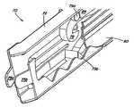
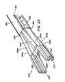
- FIG. 1is a perspective view of a clip applier constructed in accordance with the subject matter disclosed herein;
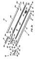
- FIG. 2 ais a perspective view of a shaft assembly of a clip applier in accordance with the subject matter disclosed herein;
- FIG. 2 bis an assembly view of the shaft assembly depicted in FIG. 2 a;
- FIG. 2 cis an enlarged assembly view of portions of the shaft assembly depicted in FIG. 2 b;
- FIG. 3 ais a cross-sectional view, taken in a plane parallel to the jaw members, of a shaft assembly of a clip applier in accordance with the subject matter disclosed herein;
- FIG. 3 bis a cross-sectional view, taken in a plane perpendicular to the jaw members, of a shaft assembly of a clip applier in accordance with the subject matter disclosed herein;
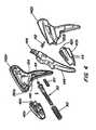
- FIG. 4is an assembly view of a handle assembly in accordance with the subject matter disclosed herein;
- FIG. 5is a perspective view of the interior of a handle assembly in accordance with the subject matter disclosed herein;
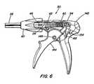
- FIG. 6is a partial cut-away view of a handle assembly in accordance with the subject matter disclosed herein;
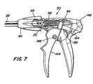
- FIG. 7is a partial cut-away view of a handle assembly in accordance with the subject matter disclosed herein;
- FIGS. 8-10are partial cut-away views of a clip channel during a clip advancing process
- FIG. 11is a partial cut-away view of a handle assembly in accordance with an embodiment of the subject matter disclosed herein;
- FIGS. 12-14are perspective views of the jaw assembly during the process of closing a clip
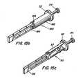
- FIGS. 15 a - 15 care a perspective views of alternate embodiments of yokes in accordance with the subject matter disclosed herein;
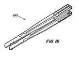
- FIGS. 16-17are perspective views of jaw assemblies in accordance with the subject matter disclosed herein;
- FIG. 18is a perspective view of a collar in accordance with an embodiment of the subject matter disclosed herein;
- FIG. 19is a perspective view of the distal end of a feeder bar in accordance with an embodiment of the subject matter disclosed herein;
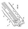
- FIG. 20is a perspective view of the distal end of a clip channel in accordance with an embodiment of the subject matter disclosed herein;
- FIGS. 21-24are perspective views of an alternate embodiment of a jaw assembly in accordance with the subject matter disclosed herein.
- FIG. 25is a perspective view of an alternate embodiment of a collar in accordance with the subject matter disclosed herein.
- an exemplary embodiment of an endoscopic clip applier 10 in accordance with the subject matter disclosed hereinincludes an elongate or shaft assembly, generally designated 20 , a jaw assembly generally designated 90 disposed at a distal end thereof, and a handle assembly generally designated 140 disposed at a proximal end thereof.
- the handle assembly 140includes a stationary grip 142 and a moveable trigger 144 for actuating the clip applier 10 .
- the jaw assembly 90may be positioned inside a body cavity, for example by passing the shaft assembly 20 through an endoscopic cannula, to apply a ligating clip to a body vessel.
- FIG. 2 ais a perspective view and FIGS. 2 b and 2 c are exploded assembly views of an exemplary embodiment of shaft assembly 20 and jaw assembly 90 .
- Shaft assembly 20includes an elongate member such as a cylindrical outer shaft member 22 , which may be formed from two semi-cylindrical outer shaft members 22 a and 22 b , respectively. It will be appreciated that outer shaft member 22 may be formed from a single tubular member, or may be of a rectangular or polygonal cross-section.
- Outer shaft member 22includes a proximal flange, indicated by proximal flange half sections 24 a , 24 b extending from the cylindrical surface of shaft members 22 a and 22 , respectively.
- Outer shaft member 22further includes pin slots 28 a , 28 b formed in the cylindrical surface.
- the cylindrical surface of outer shaft members 22 a , 22 binclude opposing channels 26 a , 26 b that define opposing slots when shaft member 22 is assembled.
- Outer shaft 22may be formed from a suitably rigid material, e.g., a suitable polymer or metal.
- shaft 22may taper from a cylindrical cross-section to a substantially rectangular cross-section.
- shaft assembly 20can include a collar 32 serving as a distal end section or interface between the main portion of outer shaft 22 and jaw assembly 90 .
- Collar 32has keys 34 a , 34 b that interlock with key slots 30 a , 30 b for connecting the collar 32 to outer shaft member 22 .
- collar 32preferably is substantially rectangular in cross-section and includes four cam surfaces 38 a , 38 b , 38 c , 38 d and opposing keys 36 a , 36 b at its distal end.
- Collar 32may be formed from suitably rigid material, e.g., a suitable polymer or metal.
- a clip feed assembly 70is disposed within the shaft 22 and collar 32 .
- Clip feed assembly 70includes a channel 72 for housing clips 78 (FIG. 2 b ), and feeder bar 80 that is moveable along the longitudinal axis of shaft 22 for moving clips disposed in channel 72 toward the distal end of the applier 10 .
- Channel 72includes a pin hole 74 near the proximal end and a plurality of tabs 76 near its base.
- Channel 72may be formed from suitably rigid material, e.g., a suitable polymer or metal.
- Feeder bar 80includes a pin slot 82 and a plurality of tabs 84 which act as clip advancing elements to move the clips 78 in channel 72 toward the distal end of the applier 10 .
- Each tab 84may be formed by stamping or cutting a portion of the body of the feeder bar 80 .
- the tab 84remains attached to the body of the feeder bar 80 at the proximal end of the tab 84 .
- Each tab 84may be bent or otherwise directed toward the interior of the clip channel 72 .
- the tabs 84may have a substantially uniform length, which may be determined by the length and geometry of the endoscopic clip, and by the rigidity of the material from which the feeder bar 80 is manufactured.
- the tabs 84may be located along either the top or bottom (or both) edges of the side of the clip channel.
- Feeder bar 80may be formed from suitably rigid material, e.g., a suitable polymer or metal.
- shaft assembly 20further includes a yoke, generally designated 50 , a portion of which is disposed within the handle assembly 140 (FIG. 1 ), for translating longitudinal motion to feeder bar 80 and outer shaft 22 .
- Feeder bar 80includes a tab 86 that rests adjacent an interior distal edge 57 of yoke 50 (see also FIG. 15 c ).
- a portion of the yoke body 56extends along a portion of the length of feeder bar 80 and has a slot 58 that aligns with pin slot 82 when yoke 50 is connected to feeder bar 80 .
- Yoke 50further includes a flange 52 and pin 54 on its proximal end.
- Yoke 50may be formed from suitably rigid material, e.g., a suitable polymer or metal.
- a feeder spring 60is positioned within the body 56 of yoke 50 for biasing the feeder bar 80 toward the distal end of yoke 50 .
- a tube spring 62is positioned between flange 52 and a flange (shown as flange halves 42 a and 42 b ) on knob 40 for biasing the yoke 50 toward the proximal end of the shaft assembly 20 .
- a knob spring 64is disposed within knob 40 and biases the outer shaft 22 in a proximal direction.
- jaw assembly 90is connected to the distal end of clip channel 72 .
- Jaw assembly 90includes a first jaw member 92 having a first leg 94 and a second leg 99 connected by a bridge member 104 .
- First leg 94includes a first cam surface 96 and a first jaw arm 98
- second leg 99includes a second cam surface 100 and a second jaw arm 102 .
- Bridge member 104includes a slot 106 for receiving a conventional fastener (e.g., rivets, pins, screws, tabs, etc.) to connect first jaw member 92 to channel 72 .
- Jaw assembly 90further includes a second jaw member 110 having a third leg 112 and a fourth leg 118 connected by a bridge member 124 .
- Third leg 112includes a third cam surface 114 and a third jaw arm 116
- fourth leg 118includes a fourth cam surface 120 and a fourth jaw arm 122
- Bridge member 124includes a slot 126 for receiving a conventional fastener (e.g., rivets, pins, screws, tabs, etc.) to connect second jaw member 110 to channel 72
- Jaw assembly 90further includes a first guide 130 adapted to clip over first jaw arm 98 and third jaw arm 116 and a second guide 132 adapted to clip over second jaw arm 102 and fourth jaw arm 122 .
- Jaw assembly 90may be formed from suitably rigid material, e.g., a suitable polymer or metal.
- FIGS. 3 a and 3 bare cross-sectional views of an assembled shaft assembly 20 of a clip applier 10 in accordance with the subject matter disclosed herein.
- the jaw assembly 90 , clip feed assembly 70 , and yoke 50are connected as described herein and extend through outer shaft 22 .
- Knob 40is mounted to the exterior of shaft 22 and secured using conventional fasteners (e.g., pins, rivets, screws, adhesives, etc.).
- a pin 46 extending through knob 40 and through pin hole 74 (FIG. 2 c ) in channel 72retains channel 72 in a fixed position with respect to knob 40 .
- 3 aillustrates a clip channel 72 having a single clip 78 , but it will be appreciated that the clip channel 72 may be filled with a plurality (e.g., 2-100) clips.
- the diameter of shaft 22is determined by the diameter of the cannula through which the shaft 22 must pass to enter a body cavity. Many existing surgical procedures use a cannula having an inner diameter measuring approximately 10 millimeters. Accordingly, in one embodiment of the invention, the shaft 22 has an outer diameter slightly less than 10 millimeters. In an alternate embodiment, the shaft 22 may be dimensioned to fit within a cannula having a diameter of 5 millimeters. It will be appreciated, however, that the diameter of the shaft 22 is not critical to the invention; any other diameter may be used as desired.
- a handle assembly 140includes a fixed grip 142 , which may be manufactured in two substantially symmetrical parts 142 a , 142 b .
- a trigger 144is pivotally mounted to fixed grip 142 about a pivot point 146 .
- trigger 144includes a grooved claw 148 that impinges on flange 52 to translate the rotary motion of trigger 144 about pivot point 146 to linear motion of yoke 50 relative to fixed grip 142 in the distal direction.
- Grooved claw 148also receives the pin 54 of yoke 50 . This arrangement enables a user to force yoke 50 in a proximal direction if necessary, which provides a safety feature.
- Fixed grip 142further includes a rim 150 that secures the flange 42 of knob 40 , such that knob 40 and channel 72 are maintained in a substantially fixed longitudinal position relative to fixed grip 142 .
- the entire shaft assembly 20is rotatable about its longitudinal axis, and knob 40 includes fins 44 (FIG. 4) that facilitate rotating the shaft assembly 20 .
- a ratchet key 152extends from the rear of trigger 144 and contacts ratchet guide 154 to inhibit backward motion of trigger 144 through a portion of the actuation stroke.
- the toothed surface portion of ratchet guide 154corresponds to the range of motion trigger claw 148 covers while the feeder bar 80 is moved forward to advance the clips in clip channel 72 (i.e., the feed stroke).
- the smooth surface portion of ratchet guide 154preferably corresponds to the range of motion trigger claw 148 covers during the portion of the actuation stroke that closes the jaw assembly 90 .
- the transition of the ratchet key 152 from the ratchet surface portion to the smooth surface portionprovides the user with tactile feedback indicating that the feed stroke is complete and a clip 78 has been fed to the jaw assembly 90 .
- the smooth surface portionpermits a user to approximate a clip.
- FIGS. 1-5Basic structural elements of one embodiment of a clip applier 10 have been described with reference to FIGS. 1-5. The interaction of the structural elements and the operation of the device will be explained with reference to FIGS. 6-24.
- FIG. 6is a partial cut-away, side view of the proximal end of clip applier 10 with the device in an unactuated state.
- yoke 50is biased to its most proximal position by tube spring 62 .
- jaw assembly 90is partially open, as depicted in FIG. 1 .
- Trigger 144 and yoke 50in combination, may be considered an actuation assembly for actuating the clip feed assembly 70 and the jaw assembly 90 .
- FIG. 7is a side cut-away view of the proximal end of clip applier 10 with the device in a partially actuated state.
- Forward motion of yoke 50places tube spring 62 under compression.
- the spring coefficient of feeder spring 60(FIG. 6) is higher than the amount of force required to advance the feeder bar 80 . Therefore, the feeder spring 60 effectively functions as a solid piece of material during the feed stroke.
- the first portion of the stroke of trigger 144is a feed stroke that advances yoke 50 and feeder bar 80 relative to the fixed channel 72 .
- the tabs 84engage the clips 78 in channel 72 and advance the clips 78 toward the distal end of applier 10 .
- the most distal clip 78is fed into the jaw assembly 90 (FIG. 1 ).
- FIGS. 8-10are partial cut-away views of the clip feeder assembly 70 illustrating the advancement or indexing of clip 78 to the most distal position during the feed stroke. For clarity of illustration, the distal end of feed bar 80 has been cut-away in FIGS. 8-10.
- FIGS. 8-10illustrate the advance of a single clip 78 toward the distal end of applier 10 , but it will be appreciated that the clip channel 72 may include a plurality (e.g., 2-100) of clips 78 , each of which is advanced by a tab 84 of feeder bar 80 . In one embodiment, channel 72 holds twenty (20) clips.
- the distal end of channel 72 and feeder bar 80include structural features adapted to feed the most distal clip into the jaw assembly 90 .
- the distal end of feeder bar 80includes a feeder tab 88 adapted to contact the central, rear portion of the most distal clip 78 to push the clip 78 into the jaw assembly 90 .
- feeder bar 80includes a foot member 89 that rotates the rear of the most distal clip 78 during the return stroke so the rear portion of the clip 78 is positioned to contact feeder tab 88 . The resulting alignment of the rear portion of clip 78 with feeder tab 88 is shown, for example, in FIG. 12 .
- FIG. 12generally corresponds to the time at which clip 78 has been loaded into jaw assembly 90 and jaw assembly 90 and clip 78 have been opened wider (as described below) during the forward stroke.
- the rear portion of clip 78is rotated by foot member 89 into alignment with feeder tab 88 during the return stroke that precedes the forward (clip feeding and clip opening) stroke.
- the interior surfaces of the jaw assembly 90 that receive the clips 78are of substantially the same width as the channel 72 to provide a smooth transition between the channel 72 and the jaw assembly 90 .
- the distal end of channel 72includes a tab 71 that catches the boss 79 b (shown, e.g., in FIGS. 8-10 and 12 - 14 ) on the most distal clip 78 when the foot member 89 (FIG. 19) of feeder bar 80 rotates the clip 78 during the return stroke, thereby limiting the rotation of the clip 78 .
- opposing ribs 73 a , 73 bfacilitate centering the rear of the most distal clip 78 (in the lateral direction) so the rear portion of the clip 78 is positioned to contact feeder tab 88 (FIG. 19 ).
- the distal end of channel 72further includes upper and lower tabs 77 a , 77 b to provide a surface that facilitates the transfer of the clip 78 into the jaw assembly 90 .
- opposing lateral tabs 75 a , 75 bserve to guide the clip 78 into the jaw assembly 90 and to inhibit lateral motion of the rear portion of the clip 78 when the clip 78 is in the jaw assembly 90 .
- FIG. 20also provides a view of tabs 76 that inhibit clips 78 from sliding in a proximal direction during the return stroke of feeder bar 80 , and of tabs 179 a - 179 d for securing a jaw member to clip channel 72 .
- the applier 10is configured such that further actuation of the trigger 144 (FIGS. 6 and 7) functions to open a clip 78 disposed in the jaw assembly 90 .
- the clips 78are fed through channel 72 in a compressed configuration, which reduces the required diameter of the shaft assembly 22 .
- the most distal clip 78is fed into the jaw assembly 90 in the same compressed configuration.
- first arm 98 , second arm 102 , third arm 116 and fourth arm 122 of respective first leg 94 , second leg 99 , third leg 112 and fourth leg 118 of jaw assembly 90include respective catch structures such as first hook 98 a , second hook 102 a , third hook 116 a and fourth hook 122 a .
- Hooks 98 a , 102 a , 116 a , 122 alimit the forward motion of clip 78 in jaw assembly 90 . Therefore, when further pressure is applied to the rear of clip 78 via the feeder tab 88 of feeder bar 80 , the force is translated through the legs of clip 78 , which causes the jaw assembly 90 (and the clip 78 contained therein) to open wider.
- the width to which the jaw assembly 90may be limited by the cam surfaces 38 a - 38 d of collar 32 .
- FIG. 11is a side cut-away view of the proximal end of clip applier 10 with the device in a fully actuated state.
- Pin 46is always in clearance with the channel 26 in shaft member 22 .
- a rib 149 in handle body 142limits the forward motion of the claw 148 portion of trigger 144 , and hence limits the forward motion of yoke 50 .
- FIGS. 12-14are perspective views of distal end of applier 10 illustrating the jaw assembly 90 while it is being closed.
- a clip 78is positioned in the jaw assembly 90 , which is in an open configuration.
- the second portion of the stroke of trigger 144closes the jaw assembly 90 . More particularly, referring to FIGS. 13-14, the second portion of the stroke moves outer shaft 22 in a distal direction relative to the fixed grip 142 (FIG. 1 ), knob 40 (FIG. 1 ), and clip channel 72 (FIGS. 2 b and 2 c ).
- cam surfaces 38 a - 38 d of collar 32impinge on cam surfaces 96 , 100 , 114 , 120 , closing the jaw assembly 90 .
- the use of four separate camsreduces the likelihood of scissoring as the jaw assembly 90 is closed.
- Each jaw arm 98 , 102 , 116 , 122terminates in a hook 98 a , 102 a , 116 a , 122 a , respectively.
- Hooks 98 a and 116 a of first jaw arm 98 and third jaw arm 116cooperate to retain boss 79 a of clip 78 in jaw assembly 90 .
- hooks 102 a and 122 a of second jaw arm 102 and fourth jaw arm 122cooperate to retain boss 79 b of clip 78 in jaw assembly 90 .
- jaw assembly 90provides four distinct points of contact between jaw assembly 90 and clip 78 , which reduces the likelihood of the jaw assembly 90 scissoring while it is closing. In addition, this configuration permits the force applied by the jaw assembly 90 to be applied to the distal end of the clip 78 , which facilitates locking the clip 78 .
- the rear (i.e., proximal) portion of clip 78is retained between tabs 75 a , 75 b extending from the distal end of clip channel 72 , which limits the range of lateral motion available to clip 78 .
- the feed tab 88(FIG.
- feed bar 80prevents the rear (i.e., proximal) portion of clip 78 from being pushed back into the clip channel 72 when the clip 78 is being applied. Accordingly, the clip 78 is maintained stable in three dimensions while retained in the jaw assembly 90 .
- only a portion of the ratchet guide 154includes ratchet teeth.
- the length of ratchet guide 154 having teethcorresponds to the feed portion of the actuation stroke of trigger 144 . Reversing the direction of feeder bar 80 during the feed stroke may cause the clip to become unstable, or even to fall out of the jaw assembly 90 .
- the teeth on ratchet guide 154inhibit feeder bar 80 from being moved in a proximal direction during the feed stroke.
- a second portion of ratchet guide 154which preferably corresponds to the portion of the stroke during which the jaw assembly 90 is closed, permits the yoke 50 and the outer shaft 22 to move freely in the distal direction and the proximal direction. This allows a user to “approximate” a clip 78 during the closing process, i.e., to partially close a clip 78 then to re-open jaw assembly 90 to reposition a clip 78 , if necessary.
- the distal collar keys 36 a , 36 bprovide a stop to prevent jaw assembly 90 from unintended closings during use, e.g., under compression as may be incurred during use in the body.
- the distal portion of collar keys 36 a , 36 binclude an inwardly-turned segment positioned to block the legs 112 and 118 from closing.
- the leg members 94 , 99 , 112 , and 118taper inwardly near the distal end of jaw assembly 90 . Therefore, as illustrated in FIG.
- the keys 36 a , 36 badvance past the respective tapers in leg members 94 , 99 and 112 , 118 , allowing jaw assembly 90 to close. Additionally, the collar keys 36 a , 36 b function as cams to facilitate re-opening jaw assembly 90 after the device is actuated and outer shaft 22 retracts.
- FIG. 14illustrates the jaw assembly 90 in a substantially closed configuration. Further actuation of the jaw assembly 90 will lock the clip 78 .
- the distal motion of outer shaft 22compresses the knob spring 64 (FIGS. 2 b and 2 c ) between the flange 24 a , 24 b (FIGS. 2 b and 2 c ) and the interior distal edge of knob 40 (FIGS. 2 b and 2 c ), which provides the bias force to return trigger 144 and outer shaft 22 to their unactuated states (FIG. 6 ).
- the usermay release the trigger 144 , and the bias force provided by knob spring 64 urges shaft 22 and feeder bar 80 in a proximal direction. This “resets” the applier 10 back to an unactuated state so that another clip may be fed to the jaw assembly 90 .
- the tabs 76(FIG. 20) on clip channel 72 inhibit the clips 78 in channel 72 from moving in the proximal direction.
- the tabs 84(FIG. 19) on the feeder bar 80 move across the clips 78 in channel 72 and snap into position behind the bosses of the clips 78 .
- the foot member 89 of the feeder bar 80contacts the boss 79 b (FIG. 12) of the most distal clip 78 in the clip channel 72 , causing the clip 78 to rotate. Rotation of the most distal clip 78 stops when the boss 79 a (FIG. 12) contacts the most distal tab 71 (FIG.
- clip channel 72which preferably positions the rear of clip 78 substantially in the center of the channel 72 .
- the feed tab 88is positioned adjacent the rear of the most distal clip 78 , ready for the next actuation cycle.
- FIGS. 15 a - 15 billustrate alternate embodiments of a yoke in accordance with the subject matter disclosed herein.
- FIG. 15 ais a perspective view of an alternate embodiment of a two-part yoke, generally designated 180 , prior to assembly
- FIG. 15 bis a perspective view of yoke 180 after assembly.
- Yoke 180includes a first body portion 182 and a second body portion 184 connected by a pin 186 .
- the feeder spring 60(FIG. 6) may be disposed entirely within the first body portion 182 of yoke 180 .
- yoke 180is substantially similar to yoke 50 . Advantages of a two-piece yoke 180 as depicted in FIGS.
- FIG. 15 a - 15 binclude better retention of feeder spring 60 within the body of the yoke 180 and ease of assembly.
- FIG. 15 cis a perspective view of yoke 50 depicted in FIG. 2, but from the opposite side to illustrate the interior distal edge 57 that receives the tab 86 (FIGS. 2 b and 2 c ) of feeder bar 80 .
- FIGS. 16-17are perspective views of alternate embodiments of jaw assemblies, generally designated 190 and 195 , respectively, in accordance with the subject matter disclosed herein.
- the jaw assemblies 190 and 195 depicted in FIGS. 16-17are substantially similar to jaw assembly 90 , but are particularly advantageous when used with an applier 10 having a shaft assembly 20 with a smaller diameter, e.g., 5 millimeters.
- the principal distinction between the jaw assemblies 190 and 195 depicted in FIGS. 16-17 and jaw assembly 90is the elimination of bridge members 104 , 124 (FIG. 2 c ) in favor of making each jaw member a discrete component.
- FIGS. 21-24are perspective views of the distal end of a clip applier 10 illustrating an alternate embodiment of a jaw assembly, generally designated 200 .
- FIG. 21illustrates the distal end of the applier 10 with the collar 32 removed to better illustrate the jaw assembly 200 .
- the jaw assembly 200includes a first jaw member 210 including leg member 212 a connected to the clip channel 72 at a pivot point 216 a , and leg member 212 b connected to the clip channel 72 at a pivot point (not visible) on the opposite side of clip channel 72 .
- Each leg member 212 a , 212 bhas a respective cam surface 214 a , 214 b .
- the distal end of the jaw assembly 200forms a first jaw 218 .
- the second jaw member 220may be substantially identical to the first jaw member 210 .
- Second jaw member 220includes leg member 222 a connected to the clip channel 72 at a pivot point 226 a , and leg member 222 b (FIG. 23) connected to clip channel 72 at a pivot point (not visible) on the opposite side of clip channel 72 .
- Leg member 222 ahas a cam surface 224 a
- leg member 222 b(FIG. 23) has a similar cam surface (not visible).
- the distal end of the jaw assembly 200forms a second jaw 228 .
- Tabs 240 , 242extend from the surface of clip cartridge 72 and function as cams to bias the proximal ends of jaw legs 212 a and 222 a , respectively, outwardly.
- a corresponding pair of tabs(not visible) extending from the opposite surface of clip cartridge 72 can be provided as cams to bias the proximal ends of jaw legs 212 b and 222 b outwardly. This tends to bias the jaw assembly 200 toward a closed configuration.
- FIGS. 22-24are sequence views of the distal end of the applier 10 that illustrate closing the jaw assembly 200 .
- FIG. 22depicts the jaw assembly 200 in the clip feed position, in which the jaws 218 , 228 preferably are substantially aligned with surfaces of the clip channel 72 to facilitate the smooth transfer of a clip 78 from the clip channel 72 into the jaw assembly 200 .
- tabse.g., tabs 240 , 242 shown in FIG.
- jaw legs 212 a , 212 b , 222 a , 222 bbias the proximal ends of jaw legs 212 a , 212 b , 222 a , 222 b , respectively outwardly.
- Collar 32limits the outward motion of the proximal ends of jaw legs 212 a , 212 b , 222 a , 222 b , respectively, which preferably are dimensioned such that the jaw assembly 200 is at rest as depicted in FIG. 22 .
- FIG. 23depicts the jaw assembly 200 in an open configuration. As discussed above, driving a clip 78 in the jaw assembly 200 forward will open the jaw assembly 200 (the clip 78 is omitted in FIG. 23 for clarity of illustration). The opening of the jaw assembly 200 is limited by contact between the cam surfaces 214 a , 214 b , 224 a (as well as the cam surface for leg member 222 b , not visible) of the jaw members 210 and 220 and the corresponding cam surfaces 38 a - 38 d of the collar 32 .
- FIG. 24depicts the jaw assembly 200 in a closed configuration.
- cams 38 a - 38 dimpinge on the cam surfaces 214 a , 214 b , 224 a (as well as the cam surface of leg member 222 b , not visible), which closes the jaw assembly 200 .
- Collar 32includes slots (e.g., slots 35 a and 35 c and opposing slots not visible) that allow the respective rear portions of jaw legs 212 a , 212 b , 222 a , 222 b to extend outwardly so that the jaws 218 , 228 can close.
- FIG. 25depicts an alternate embodiment of a collar 250 adapted for use with the jaw assembly 200 depicted in FIGS. 21-24.
- Collar 250is substantially similar to the collar 32 depicted in FIGS. 21-24, and includes a tab 252 that extends into the chamber defined by the collar 250 to prevent jaw members 210 , 220 from unintended closing, e.g., due to pressure inside the body cavity.
- tab 252fits between leg members 212 a , 222 a to prevent jaw assembly 200 from closing.
- the tab 252moves distally, allowing the jaw assembly 200 to close.
- the clip cartridge 72is retained substantially in a fixed spatial relationship with the fixed grip 142 , and the actuation assembly moves the feeder bar 80 to advance clips 78 in the clip channel 72 and outer shaft assembly 20 to close the jaw assembly 90 .
- the shaft assembly 20could remain fixed, and the actuation assembly could move the clip channel 72 relative to the fixed shaft 22 to close the jaw assembly 90 .
- the clip channel 72could be biased in a distal direction and the pivot point 146 of trigger 144 could be repositioned such that actuating the trigger 144 retracts clip channel 72 in a proximal direction.
- feeder bar 80could be fixed, such that retracting clip channel 72 in a proximal direction advances clips 78 in the clip channel 72 .
Landscapes
- Health & Medical Sciences (AREA)
- Surgery (AREA)
- Life Sciences & Earth Sciences (AREA)
- Heart & Thoracic Surgery (AREA)
- Nuclear Medicine, Radiotherapy & Molecular Imaging (AREA)
- Vascular Medicine (AREA)
- Engineering & Computer Science (AREA)
- Biomedical Technology (AREA)
- Reproductive Health (AREA)
- Medical Informatics (AREA)
- Molecular Biology (AREA)
- Animal Behavior & Ethology (AREA)
- General Health & Medical Sciences (AREA)
- Public Health (AREA)
- Veterinary Medicine (AREA)
- Surgical Instruments (AREA)
Abstract
Description
Claims (9)
Priority Applications (6)
| Application Number | Priority Date | Filing Date | Title |
|---|---|---|---|
| US09/905,679US6824547B2 (en) | 2001-07-13 | 2001-07-13 | Endoscopic clip applier and method |
| JP2003511691AJP4263594B2 (en) | 2001-07-13 | 2002-07-02 | Endoscopic clip applier and application method |
| EP12004149.6AEP2548521B1 (en) | 2001-07-13 | 2002-07-02 | Endoscopic clip applier |
| EP02752137AEP1416860A4 (en) | 2001-07-13 | 2002-07-02 | Endoscopic clip applier and method |
| PCT/US2002/020866WO2003005878A2 (en) | 2001-07-13 | 2002-07-02 | Endoscopic clip applier and method |
| ES12004149.6TES2676875T3 (en) | 2001-07-13 | 2002-07-02 | Endoscopic stapler applicator |
Applications Claiming Priority (1)
| Application Number | Priority Date | Filing Date | Title |
|---|---|---|---|
| US09/905,679US6824547B2 (en) | 2001-07-13 | 2001-07-13 | Endoscopic clip applier and method |
Publications (2)
| Publication Number | Publication Date |
|---|---|
| US20030014060A1 US20030014060A1 (en) | 2003-01-16 |
| US6824547B2true US6824547B2 (en) | 2004-11-30 |
Family
ID=25421262
Family Applications (1)
| Application Number | Title | Priority Date | Filing Date |
|---|---|---|---|
| US09/905,679Expired - LifetimeUS6824547B2 (en) | 2001-07-13 | 2001-07-13 | Endoscopic clip applier and method |
Country Status (5)
| Country | Link |
|---|---|
| US (1) | US6824547B2 (en) |
| EP (2) | EP2548521B1 (en) |
| JP (1) | JP4263594B2 (en) |
| ES (1) | ES2676875T3 (en) |
| WO (1) | WO2003005878A2 (en) |
Cited By (163)
| Publication number | Priority date | Publication date | Assignee | Title |
|---|---|---|---|---|
| US20030229360A1 (en)* | 2002-05-31 | 2003-12-11 | Gayton John F. | Tissue fastener having a shaft with a reduced cross-section |
| US20040097970A1 (en)* | 2002-11-19 | 2004-05-20 | Hughett J. David | Automated-feed surgical clip applier and related methods |
| US20050021061A1 (en)* | 2003-07-25 | 2005-01-27 | Dennis William G. | Occlusion clip and method of applying same |
| US20070049949A1 (en)* | 2005-08-25 | 2007-03-01 | Microline Pentax Inc | Clip feeder mechanism for clip applying device |
| US20070185504A1 (en)* | 2005-08-25 | 2007-08-09 | Microline Pentax, Inc. | Medical clip feeding mechanism |
| US20080065118A1 (en)* | 2001-10-24 | 2008-03-13 | Damarati John J | Multiple hemoclip system for an endoscope |
| US20080188872A1 (en)* | 2006-12-13 | 2008-08-07 | Michael Duff | Multi-mode clip applier, and associated method |
| US7637917B2 (en) | 2004-10-08 | 2009-12-29 | Tyco Healthcare Group Lp | Endoscopic surgical clip applier |
| US7819886B2 (en) | 2004-10-08 | 2010-10-26 | Tyco Healthcare Group Lp | Endoscopic surgical clip applier |
| US7887553B2 (en)* | 2001-07-09 | 2011-02-15 | Tyco Healthcare Group Lp | Right angle clip applier apparatus and method |
| US8056565B2 (en) | 2008-08-25 | 2011-11-15 | Tyco Healthcare Group Lp | Surgical clip applier and method of assembly |
| US8128643B2 (en) | 2006-10-17 | 2012-03-06 | Tyco Healthcare Group Lp | Apparatus for applying surgical clips |
| US8147489B2 (en) | 2005-01-14 | 2012-04-03 | Covidien Ag | Open vessel sealing instrument |
| US8197633B2 (en) | 2005-09-30 | 2012-06-12 | Covidien Ag | Method for manufacturing an end effector assembly |
| US8267944B2 (en) | 2008-08-29 | 2012-09-18 | Tyco Healthcare Group Lp | Endoscopic surgical clip applier with lock out |
| US8382773B2 (en) | 2007-03-26 | 2013-02-26 | Covidien Lp | Endoscopic surgical clip applier |
| US8403946B2 (en) | 2010-07-28 | 2013-03-26 | Covidien Lp | Articulating clip applier cartridge |
| US8403945B2 (en) | 2010-02-25 | 2013-03-26 | Covidien Lp | Articulating endoscopic surgical clip applier |
| US8409223B2 (en) | 2008-08-29 | 2013-04-02 | Covidien Lp | Endoscopic surgical clip applier with clip retention |
| US8409222B2 (en) | 2004-10-08 | 2013-04-02 | Covidien Lp | Endoscopic surgical clip applier |
| USD680220S1 (en) | 2012-01-12 | 2013-04-16 | Coviden IP | Slider handle for laparoscopic device |
| US8454602B2 (en) | 2009-05-07 | 2013-06-04 | Covidien Lp | Apparatus, system, and method for performing an electrosurgical procedure |
| US8465502B2 (en) | 2008-08-25 | 2013-06-18 | Covidien Lp | Surgical clip applier and method of assembly |
| US8506580B2 (en) | 2007-04-11 | 2013-08-13 | Covidien Lp | Surgical clip applier |
| US8523898B2 (en) | 2009-07-08 | 2013-09-03 | Covidien Lp | Endoscopic electrosurgical jaws with offset knife |
| US8545486B2 (en) | 2009-12-15 | 2013-10-01 | Covidien Lp | Surgical clip applier |
| US8551091B2 (en) | 2002-10-04 | 2013-10-08 | Covidien Ag | Vessel sealing instrument with electrical cutting mechanism |
| US8568444B2 (en) | 2008-10-03 | 2013-10-29 | Covidien Lp | Method of transferring rotational motion in an articulating surgical instrument |
| US8585717B2 (en) | 2008-08-29 | 2013-11-19 | Covidien Lp | Single stroke endoscopic surgical clip applier |
| US8591506B2 (en) | 1998-10-23 | 2013-11-26 | Covidien Ag | Vessel sealing system |
| US8597296B2 (en) | 2003-11-17 | 2013-12-03 | Covidien Ag | Bipolar forceps having monopolar extension |
| US8679140B2 (en) | 2012-05-30 | 2014-03-25 | Covidien Lp | Surgical clamping device with ratcheting grip lock |
| US8734469B2 (en) | 2009-10-13 | 2014-05-27 | Covidien Lp | Suture clip applier |
| US8852228B2 (en) | 2009-01-13 | 2014-10-07 | Covidien Lp | Apparatus, system, and method for performing an electrosurgical procedure |
| US8898888B2 (en) | 2009-09-28 | 2014-12-02 | Covidien Lp | System for manufacturing electrosurgical seal plates |
| US8968337B2 (en) | 2010-07-28 | 2015-03-03 | Covidien Lp | Articulating clip applier |
| US9011464B2 (en) | 2010-11-02 | 2015-04-21 | Covidien Lp | Self-centering clip and jaw |
| US9028493B2 (en) | 2009-09-18 | 2015-05-12 | Covidien Lp | In vivo attachable and detachable end effector assembly and laparoscopic surgical instrument and methods therefor |
| US9113940B2 (en) | 2011-01-14 | 2015-08-25 | Covidien Lp | Trigger lockout and kickback mechanism for surgical instruments |
| US9113898B2 (en) | 2008-10-09 | 2015-08-25 | Covidien Lp | Apparatus, system, and method for performing an electrosurgical procedure |
| US9113892B2 (en) | 2013-01-08 | 2015-08-25 | Covidien Lp | Surgical clip applier |
| US9186136B2 (en) | 2009-12-09 | 2015-11-17 | Covidien Lp | Surgical clip applier |
| US9186153B2 (en) | 2011-01-31 | 2015-11-17 | Covidien Lp | Locking cam driver and jaw assembly for clip applier |
| US9326776B2 (en) | 2005-09-29 | 2016-05-03 | Applied Medical Resources Corporation | Manually actuated surgical clip applier |
| US9358015B2 (en) | 2008-08-29 | 2016-06-07 | Covidien Lp | Endoscopic surgical clip applier with wedge plate |
| US9364216B2 (en) | 2011-12-29 | 2016-06-14 | Covidien Lp | Surgical clip applier with integrated clip counter |
| US9364239B2 (en) | 2011-12-19 | 2016-06-14 | Covidien Lp | Jaw closure mechanism for a surgical clip applier |
| US9408610B2 (en) | 2012-05-04 | 2016-08-09 | Covidien Lp | Surgical clip applier with dissector |
| US9414844B2 (en) | 2008-08-25 | 2016-08-16 | Covidien Lp | Surgical clip appliers |
| US9445820B2 (en) | 2007-12-31 | 2016-09-20 | Teleflex Medical Incorporated | Ligation clip with flexible clamping feature |
| US9532787B2 (en) | 2012-05-31 | 2017-01-03 | Covidien Lp | Endoscopic clip applier |
| US9597089B2 (en) | 2010-03-10 | 2017-03-21 | Conmed Corporation | Surgical clips for laparoscopic procedures |
| US9687247B2 (en) | 2004-10-08 | 2017-06-27 | Covidien Lp | Apparatus for applying surgical clips |
| US9717504B2 (en) | 2005-04-14 | 2017-08-01 | Ethicon Llc | Clip applier with migrational resistance features |
| US9750500B2 (en) | 2013-01-18 | 2017-09-05 | Covidien Lp | Surgical clip applier |
| US9763668B2 (en) | 2004-10-08 | 2017-09-19 | Covidien Lp | Endoscopic surgical clip applier |
| US9775624B2 (en) | 2013-08-27 | 2017-10-03 | Covidien Lp | Surgical clip applier |
| US9775623B2 (en) | 2011-04-29 | 2017-10-03 | Covidien Lp | Surgical clip applier including clip relief feature |
| US9855053B2 (en) | 2011-10-20 | 2018-01-02 | Teleflex Life Sciences Unlimited Copmany | Ligation clip |
| US9931124B2 (en) | 2015-01-07 | 2018-04-03 | Covidien Lp | Reposable clip applier |
| US9968362B2 (en) | 2013-01-08 | 2018-05-15 | Covidien Lp | Surgical clip applier |
| US10136898B2 (en) | 2010-03-09 | 2018-11-27 | Teleflex Medical Incorporated | Narrow profile surgical ligation clip |
| US10159491B2 (en) | 2015-03-10 | 2018-12-25 | Covidien Lp | Endoscopic reposable surgical clip applier |
| EP3441013A1 (en)* | 2017-08-10 | 2019-02-13 | Ethicon LLC | Jaw for clip applier |
| US10213250B2 (en) | 2015-11-05 | 2019-02-26 | Covidien Lp | Deployment and safety mechanisms for surgical instruments |
| US10251696B2 (en) | 2001-04-06 | 2019-04-09 | Covidien Ag | Vessel sealer and divider with stop members |
| US10292712B2 (en) | 2015-01-28 | 2019-05-21 | Covidien Lp | Surgical clip applier with integrated cutter |
| US10307166B2 (en) | 2011-09-15 | 2019-06-04 | Teleflex Medical Incorporated | Manual surgical ligation clip applier |
| US10390831B2 (en) | 2015-11-10 | 2019-08-27 | Covidien Lp | Endoscopic reposable surgical clip applier |
| US10426489B2 (en) | 2016-11-01 | 2019-10-01 | Covidien Lp | Endoscopic reposable surgical clip applier |
| US10492795B2 (en) | 2016-11-01 | 2019-12-03 | Covidien Lp | Endoscopic surgical clip applier |
| US10548609B2 (en) | 2016-08-03 | 2020-02-04 | Teleflex Medical Incorporated | Surgical ligation clip |
| US10548602B2 (en) | 2017-02-23 | 2020-02-04 | Covidien Lp | Endoscopic surgical clip applier |
| US10582931B2 (en) | 2016-02-24 | 2020-03-10 | Covidien Lp | Endoscopic reposable surgical clip applier |
| US10603038B2 (en) | 2017-02-22 | 2020-03-31 | Covidien Lp | Surgical clip applier including inserts for jaw assembly |
| US10610236B2 (en) | 2016-11-01 | 2020-04-07 | Covidien Lp | Endoscopic reposable surgical clip applier |
| US10639044B2 (en) | 2016-10-31 | 2020-05-05 | Covidien Lp | Ligation clip module and clip applier |
| US10639032B2 (en) | 2017-06-30 | 2020-05-05 | Covidien Lp | Endoscopic surgical clip applier including counter assembly |
| US10653429B2 (en) | 2017-09-13 | 2020-05-19 | Covidien Lp | Endoscopic surgical clip applier |
| US10660723B2 (en) | 2017-06-30 | 2020-05-26 | Covidien Lp | Endoscopic reposable surgical clip applier |
| US10660651B2 (en) | 2016-10-31 | 2020-05-26 | Covidien Lp | Endoscopic reposable surgical clip applier |
| US10660652B2 (en) | 2015-10-10 | 2020-05-26 | Covidien Lp | Endoscopic surgical clip applier |
| US10660725B2 (en) | 2017-02-14 | 2020-05-26 | Covidien Lp | Endoscopic surgical clip applier including counter assembly |
| US10667824B2 (en) | 2005-04-14 | 2020-06-02 | Ethicon Llc | Surgical clip applier methods |
| US10675112B2 (en) | 2017-08-07 | 2020-06-09 | Covidien Lp | Endoscopic surgical clip applier including counter assembly |
| US10675043B2 (en) | 2017-05-04 | 2020-06-09 | Covidien Lp | Reposable multi-fire surgical clip applier |
| US10675031B2 (en) | 2017-08-10 | 2020-06-09 | Ethicon Llc | Clip retention for surgical clip applier |
| US10702280B2 (en) | 2015-11-10 | 2020-07-07 | Covidien Lp | Endoscopic reposable surgical clip applier |
| US10702279B2 (en) | 2015-11-03 | 2020-07-07 | Covidien Lp | Endoscopic surgical clip applier |
| US10702278B2 (en) | 2014-12-02 | 2020-07-07 | Covidien Lp | Laparoscopic surgical ligation clip applier |
| US10709455B2 (en) | 2017-02-02 | 2020-07-14 | Covidien Lp | Endoscopic surgical clip applier |
| US10722235B2 (en) | 2017-05-11 | 2020-07-28 | Covidien Lp | Spring-release surgical clip |
| US10722236B2 (en) | 2017-12-12 | 2020-07-28 | Covidien Lp | Endoscopic reposable surgical clip applier |
| US10743887B2 (en) | 2017-12-13 | 2020-08-18 | Covidien Lp | Reposable multi-fire surgical clip applier |
| EP3673837A3 (en)* | 2018-12-31 | 2020-08-19 | Ethicon LLC | Multi-piece jaw assembly for surgical clip applier |
| US10758244B2 (en) | 2017-02-06 | 2020-09-01 | Covidien Lp | Endoscopic surgical clip applier |
| US10758245B2 (en) | 2017-09-13 | 2020-09-01 | Covidien Lp | Clip counting mechanism for surgical clip applier |
| US10765431B2 (en) | 2016-01-18 | 2020-09-08 | Covidien Lp | Endoscopic surgical clip applier |
| US10786262B2 (en) | 2017-08-09 | 2020-09-29 | Covidien Lp | Endoscopic reposable surgical clip applier |
| US10786263B2 (en) | 2017-08-15 | 2020-09-29 | Covidien Lp | Endoscopic reposable surgical clip applier |
| US10786273B2 (en) | 2018-07-13 | 2020-09-29 | Covidien Lp | Rotation knob assemblies for handle assemblies |
| US10806463B2 (en) | 2011-11-21 | 2020-10-20 | Covidien Lp | Surgical clip applier |
| US10806464B2 (en) | 2016-08-11 | 2020-10-20 | Covidien Lp | Endoscopic surgical clip applier and clip applying systems |
| US10828036B2 (en) | 2017-11-03 | 2020-11-10 | Covidien Lp | Endoscopic surgical clip applier and handle assemblies for use therewith |
| US10835341B2 (en) | 2017-09-12 | 2020-11-17 | Covidien Lp | Endoscopic surgical clip applier and handle assemblies for use therewith |
| US10835260B2 (en) | 2017-09-13 | 2020-11-17 | Covidien Lp | Endoscopic surgical clip applier and handle assemblies for use therewith |
| US10849630B2 (en) | 2017-12-13 | 2020-12-01 | Covidien Lp | Reposable multi-fire surgical clip applier |
| US10863992B2 (en) | 2017-08-08 | 2020-12-15 | Covidien Lp | Endoscopic surgical clip applier |
| USD907200S1 (en) | 2019-08-05 | 2021-01-05 | Covidien Lp | Ligation clip |
| USD907203S1 (en) | 2019-08-02 | 2021-01-05 | Covidien Lp | Ligation clip |
| USD907204S1 (en) | 2019-08-02 | 2021-01-05 | Covidien Lp | Ligation clip |
| US10905425B2 (en) | 2015-11-10 | 2021-02-02 | Covidien Lp | Endoscopic reposable surgical clip applier |
| US10925616B2 (en) | 2017-03-21 | 2021-02-23 | Teleflex Medical Incorporated | Clip applier with replaceable tips |
| US10932789B2 (en) | 2018-04-11 | 2021-03-02 | Covidien Lp | Ligation clip with latching and retention features |
| US10932790B2 (en) | 2017-08-08 | 2021-03-02 | Covidien Lp | Geared actuation mechanism and surgical clip applier including the same |
| US10932793B2 (en) | 2016-01-11 | 2021-03-02 | Covidien Lp | Endoscopic reposable surgical clip applier |
| US10932791B2 (en) | 2017-11-03 | 2021-03-02 | Covidien Lp | Reposable multi-fire surgical clip applier |
| US10932788B2 (en) | 2018-04-11 | 2021-03-02 | Covidien Lp | Ligation clip with latching and retention features |
| US10945734B2 (en) | 2017-11-03 | 2021-03-16 | Covidien Lp | Rotation knob assemblies and surgical instruments including the same |
| US10945740B2 (en) | 2017-06-22 | 2021-03-16 | Teleflex Medical Incorporated | Surgical clip |
| US10959737B2 (en) | 2017-12-13 | 2021-03-30 | Covidien Lp | Reposable multi-fire surgical clip applier |
| US10987159B2 (en) | 2015-08-26 | 2021-04-27 | Covidien Lp | Electrosurgical end effector assemblies and electrosurgical forceps configured to reduce thermal spread |
| US10993721B2 (en) | 2018-04-25 | 2021-05-04 | Covidien Lp | Surgical clip applier |
| US11033256B2 (en) | 2018-08-13 | 2021-06-15 | Covidien Lp | Linkage assembly for reusable surgical handle assemblies |
| US11033279B2 (en) | 2018-04-24 | 2021-06-15 | Covidien Lp | Ligation clip with retention features |
| US11051827B2 (en) | 2018-01-16 | 2021-07-06 | Covidien Lp | Endoscopic surgical instrument and handle assemblies for use therewith |
| US11051828B2 (en) | 2018-08-13 | 2021-07-06 | Covidien Lp | Rotation knob assemblies and surgical instruments including same |
| US11058432B2 (en) | 2015-01-15 | 2021-07-13 | Covidien Lp | Endoscopic reposable surgical clip applier |
| US11071553B2 (en) | 2016-08-25 | 2021-07-27 | Covidien Lp | Endoscopic surgical clip applier and clip applying systems |
| US11116513B2 (en) | 2017-11-03 | 2021-09-14 | Covidien Lp | Modular surgical clip cartridge |
| US11116514B2 (en) | 2017-02-06 | 2021-09-14 | Covidien Lp | Surgical clip applier with user feedback feature |
| US11147566B2 (en) | 2018-10-01 | 2021-10-19 | Covidien Lp | Endoscopic surgical clip applier |
| US11160559B2 (en) | 2017-03-21 | 2021-11-02 | Teleflex Medical Incorporated | Clip applier with stabilizing member |
| US11219463B2 (en) | 2018-08-13 | 2022-01-11 | Covidien Lp | Bilateral spring for surgical instruments and surgical instruments including the same |
| US11246601B2 (en) | 2018-08-13 | 2022-02-15 | Covidien Lp | Elongated assemblies for surgical clip appliers and surgical clip appliers incorporating the same |
| US11253267B2 (en) | 2018-08-13 | 2022-02-22 | Covidien Lp | Friction reduction mechanisms for handle assemblies |
| US11259887B2 (en) | 2018-08-10 | 2022-03-01 | Covidien Lp | Feedback mechanisms for handle assemblies |
| US11266408B2 (en) | 2017-03-21 | 2022-03-08 | Teleflex Medical Incorporated | Clip applier having stabilizing member |
| US11278267B2 (en) | 2018-08-13 | 2022-03-22 | Covidien Lp | Latch assemblies and surgical instruments including the same |
| US11304704B2 (en) | 2018-08-22 | 2022-04-19 | Covidien Lp | Surgical clip applier and ligation clips |
| US11304703B2 (en) | 2018-05-25 | 2022-04-19 | Covidien Lp | Ligation clip removal device |
| US11317923B2 (en) | 2018-08-13 | 2022-05-03 | Covidien Lp | Ligation clip with improved hinge |
| US11344316B2 (en) | 2018-08-13 | 2022-05-31 | Covidien Lp | Elongated assemblies for surgical clip appliers and surgical clip appliers incorporating the same |
| US11376015B2 (en) | 2017-11-03 | 2022-07-05 | Covidien Lp | Endoscopic surgical clip applier and handle assemblies for use therewith |
| US11395660B2 (en) | 2019-08-05 | 2022-07-26 | Covidien Lp | Stackable ligation clip |
| US11471165B2 (en) | 2019-05-08 | 2022-10-18 | Covidien Lp | Ligation clip cartridge |
| US11524398B2 (en) | 2019-03-19 | 2022-12-13 | Covidien Lp | Gear drive mechanisms for surgical instruments |
| US11534177B2 (en)* | 2017-03-21 | 2022-12-27 | Teleflex Medical Incorporated | Flexible stabilizing member for a clip applier |
| CN115670571A (en)* | 2021-07-30 | 2023-02-03 | 苏州英途康医疗科技有限公司 | Press from both sides storehouse device and execute and press from both sides ware |
| US11583291B2 (en) | 2017-02-23 | 2023-02-21 | Covidien Lp | Endoscopic surgical clip applier |
| US11607227B2 (en) | 2017-03-21 | 2023-03-21 | Teleflex Medical Incorporated | Surgical clip and clip applier |
| US11648014B2 (en) | 2017-11-14 | 2023-05-16 | Teleflex Medical Incorporated | Surgical clip |
| US11696764B2 (en) | 2020-01-31 | 2023-07-11 | Covidien Lp | Ligation clip with controlled tissue compression |
| US11707282B2 (en) | 2019-07-02 | 2023-07-25 | Covidien Lp | Multi-piece ligation clip |
| USD993411S1 (en) | 2017-11-03 | 2023-07-25 | Covidien Lp | Ligation clip with controlled tissue compression |
| US11723669B2 (en) | 2020-01-08 | 2023-08-15 | Covidien Lp | Clip applier with clip cartridge interface |
| US11779340B2 (en) | 2020-01-02 | 2023-10-10 | Covidien Lp | Ligation clip loading device |
| US11992222B2 (en) | 2019-12-19 | 2024-05-28 | Teleflex Medical Incorporated | Surgical clip |
| US12023041B2 (en) | 2017-03-21 | 2024-07-02 | Teleflex Medical Incorporated | Clip applier |
| US12114866B2 (en) | 2020-03-26 | 2024-10-15 | Covidien Lp | Interoperative clip loading device |
| US12279774B2 (en) | 2018-09-26 | 2025-04-22 | Teleflex Medical Incorporated | Clip applier with stabilizing member |
| US12318094B2 (en) | 2019-09-26 | 2025-06-03 | Teleflex Medical Incorporated | Clip applier |
| US12419648B2 (en) | 2022-09-26 | 2025-09-23 | Covidien Lp | Two-part fasteners for surgical clip appliers and surgical clip appliers for deploying the same |
Families Citing this family (44)
| Publication number | Priority date | Publication date | Assignee | Title |
|---|---|---|---|---|
| US7331968B2 (en)* | 2004-06-14 | 2008-02-19 | Ethicon Endo-Surgery, Inc. | Endoscopic clip applier with threaded clip |
| WO2003105670A2 (en)* | 2002-01-10 | 2003-12-24 | Guided Delivery Systems, Inc. | Devices and methods for heart valve repair |
| US9949829B2 (en) | 2002-06-13 | 2018-04-24 | Ancora Heart, Inc. | Delivery devices and methods for heart valve repair |
| US8641727B2 (en) | 2002-06-13 | 2014-02-04 | Guided Delivery Systems, Inc. | Devices and methods for heart valve repair |
| EP1608272B1 (en)* | 2003-03-11 | 2017-01-25 | Covidien LP | Clip applying apparatus with angled jaw |
| US7150749B2 (en)* | 2003-06-13 | 2006-12-19 | Sherwood Services Ag | Vessel sealer and divider having elongated knife stroke and safety cutting mechanism |
| US7156846B2 (en) | 2003-06-13 | 2007-01-02 | Sherwood Services Ag | Vessel sealer and divider for use with small trocars and cannulas |
| USD956973S1 (en) | 2003-06-13 | 2022-07-05 | Covidien Ag | Movable handle for endoscopic vessel sealer and divider |
| US7837740B2 (en) | 2007-01-24 | 2010-11-23 | Musculoskeletal Transplant Foundation | Two piece cancellous construct for cartilage repair |
| US7288098B2 (en)* | 2005-04-14 | 2007-10-30 | Ethicon Endo-Surgery, Inc. | Force limiting mechanism for medical instrument |
| US8038686B2 (en)* | 2005-04-14 | 2011-10-18 | Ethicon Endo-Surgery, Inc. | Clip applier configured to prevent clip fallout |
| US7261724B2 (en)* | 2005-04-14 | 2007-08-28 | Ethicon Endo-Surgery, Inc. | Surgical clip advancement mechanism |
| US7686820B2 (en)* | 2005-04-14 | 2010-03-30 | Ethicon Endo-Surgery, Inc. | Surgical clip applier ratchet mechanism |
| US8523882B2 (en)* | 2005-04-14 | 2013-09-03 | Ethicon Endo-Surgery, Inc. | Clip advancer mechanism with alignment features |
| US7896895B2 (en)* | 2005-11-23 | 2011-03-01 | Ethicon Endo-Surgery, Inc. | Surgical clip and applier device and method of use |
| US8790367B2 (en) | 2008-02-06 | 2014-07-29 | Guided Delivery Systems Inc. | Multi-window guide tunnel |
| WO2010085456A1 (en) | 2009-01-20 | 2010-07-29 | Guided Delivery Systems Inc. | Anchor deployment devices and related methods |
| US8267945B2 (en)* | 2009-10-09 | 2012-09-18 | Ethicon Endo-Surgery, Inc. | Clip advancer with lockout mechanism |
| US8262679B2 (en)* | 2009-10-09 | 2012-09-11 | Ethicon Endo-Surgery, Inc. | Clip advancer |
| WO2012031204A2 (en) | 2010-09-03 | 2012-03-08 | Guided Delivery Systems Inc. | Devices and methods for anchoring tissue |
| EP2755576B1 (en) | 2011-09-15 | 2019-05-22 | Teleflex Medical Incorporated | Automatic surgical ligation clip applier |
| EP2768418B1 (en) | 2011-10-19 | 2017-07-19 | Ethicon Endo-Surgery, Inc. | Clip applier adapted for use with a surgical robot |
| US9474530B2 (en)* | 2013-03-14 | 2016-10-25 | C.R. Bard, Inc. | Handling of fasteners within a surgical instrument |
| US9427230B2 (en) | 2013-03-14 | 2016-08-30 | C.R. Bard, Inc. | Handling of fasteners within a surgical instrument |
| US10779838B1 (en) | 2013-11-13 | 2020-09-22 | Joseph W Blake, III | Instrument for serially applying clips to a surgical site |
| US10098641B1 (en) | 2014-08-21 | 2018-10-16 | Joseph W Blake, III | Jaws and cams for clip applying instruments |
| US9968363B2 (en) | 2014-10-20 | 2018-05-15 | Joseph W. Blake, III | Multi-clip applier |
| US10058321B2 (en) | 2015-03-05 | 2018-08-28 | Ancora Heart, Inc. | Devices and methods of visualizing and determining depth of penetration in cardiac tissue |
| AU2016260305B2 (en) | 2015-05-12 | 2022-01-06 | Ancora Heart, Inc. | Device and method for releasing catheters from cardiac structures |
| KR101781403B1 (en)* | 2016-04-27 | 2017-09-25 | 주식회사 엔도비전 | Hemostatic clip applier |
| KR101965936B1 (en)* | 2016-11-15 | 2019-04-04 | 한준모 | A Jaw Module for Preventing a Clip from Slipping in a Clip Applier and the Clip Applier for the Same |
| KR20180105783A (en)* | 2017-03-16 | 2018-10-01 | 한준모 | A Clip Jaw Unit Having a Structure of Preventing a Clip From Slipping and Deforming and An Applier Having the Same |
| WO2019031620A1 (en)* | 2017-08-08 | 2019-02-14 | 주식회사 엔도비전 | Hemostatic clip providing device |
| KR102036055B1 (en)* | 2018-01-17 | 2019-10-24 | (주)엘에이치코리아 | An Applier for a Medical Clip |
| KR102647625B1 (en)* | 2018-07-18 | 2024-03-14 | 텔리플렉스 메디컬 인코포레이티드 | Clip Appliers and Cartridges |
| AU2020253238B2 (en) | 2019-03-29 | 2025-03-06 | Gyrus Acmi, Inc. D/B/A Olympus Surgical Technologies America | Forceps motion transfer assembly |
| US11672524B2 (en) | 2019-07-15 | 2023-06-13 | Ancora Heart, Inc. | Devices and methods for tether cutting |
| CN112603451A (en)* | 2020-12-25 | 2021-04-06 | 江苏诺瑞思医疗器械有限公司 | Repeating clip applier |
| KR102315685B1 (en)* | 2021-02-09 | 2021-10-21 | (주)유원메디텍 | Automatic Polymer Clip Applier |
| CA3234122A1 (en)* | 2021-10-14 | 2023-04-20 | Jessica BOYERS | Asymmetric clip applier and cartridge |
| CN114469240B (en)* | 2022-01-25 | 2023-07-14 | 常州市康蒂娜医疗科技有限公司 | Continuous hair clip applier with detachable ligature clip assembly |
| CN115337069B (en)* | 2022-10-18 | 2023-01-10 | 苏州英途康医疗科技有限公司 | Clamping mechanism and clamping device thereof |
| CN115337067B (en)* | 2022-10-18 | 2022-12-20 | 苏州英途康医疗科技有限公司 | Clamping mechanism and clamping device thereof |
| CN115486893B (en)* | 2022-11-21 | 2023-01-31 | 苏州英途康医疗科技有限公司 | A clip applier shaft assembly and clip applier |
Citations (17)
| Publication number | Priority date | Publication date | Assignee | Title |
|---|---|---|---|---|
| US4509518A (en)* | 1982-02-17 | 1985-04-09 | United States Surgical Corporation | Apparatus for applying surgical clips |
| US4662373A (en)* | 1981-06-29 | 1987-05-05 | American Cyanamid Company | Surgical ligating instrument |
| US4834096A (en) | 1987-10-26 | 1989-05-30 | Edward Weck Incorporated | Plastic ligating clips |
| EP0409569A1 (en) | 1989-07-18 | 1991-01-23 | United States Surgical Corporation | Apparatus for applying surgical clips in laparoscopic or endoscopic procedures |
| US5100420A (en) | 1989-07-18 | 1992-03-31 | United States Surgical Corporation | Apparatus and method for applying surgical clips in laparoscopic or endoscopic procedures |
| US5156609A (en) | 1989-12-26 | 1992-10-20 | Nakao Naomi L | Endoscopic stapling device and method |
| EP0510826A1 (en) | 1991-04-04 | 1992-10-28 | Ethicon, Inc. | Endoscopic multiple ligating clip applier |
| US5207691A (en)* | 1991-11-01 | 1993-05-04 | Medical Scientific, Inc. | Electrosurgical clip applicator |
| EP0596429A1 (en) | 1992-10-30 | 1994-05-11 | United States Surgical Corporation | Apparatus and method for applying surgical clips in laparoscopic or endoscopic procedures |
| US5403327A (en) | 1992-12-31 | 1995-04-04 | Pilling Weck Incorporated | Surgical clip applier |
| US5573541A (en)* | 1990-09-13 | 1996-11-12 | United States Surgical Corporation | Apparatus and method for subcuticular stapling of body tissue |
| US5607436A (en)* | 1993-10-08 | 1997-03-04 | United States Surgical Corporation | Apparatus for applying surgical clips |
| US5626585A (en) | 1994-09-16 | 1997-05-06 | United States Surgical Corporation | Ligating clip advance |
| US5700271A (en) | 1995-10-20 | 1997-12-23 | United States Surgical Corporation | Apparatus for applying surgical clips |
| US5772673A (en)* | 1996-03-07 | 1998-06-30 | United States Surgical Corporation | Apparatus for applying surgical clips |
| US5938667A (en)* | 1995-10-20 | 1999-08-17 | United States Surgical Corporation | Surgical clip applier |
| US20020198549A1 (en)* | 2001-06-25 | 2002-12-26 | Syntheon, Llc | Surgical clip |
Family Cites Families (13)
| Publication number | Priority date | Publication date | Assignee | Title |
|---|---|---|---|---|
| US4509548A (en)* | 1982-07-01 | 1985-04-09 | The United States Of America As Represented By The Administrator Of The National Aeronautics And Space Administration | Reactant pressure differential control for fuel cell gases |
| US4598711A (en)* | 1984-08-09 | 1986-07-08 | American Cyanamid Company | Surgical instrument |
| DE9018151U1 (en)* | 1989-07-18 | 1996-11-07 | United States Surgical Corp., Norwalk, Conn. | Device for attaching surgical clips in laparoscopic or endoscopic procedures |
| US5893863A (en)* | 1989-12-05 | 1999-04-13 | Yoon; Inbae | Surgical instrument with jaws and movable internal hook member for use thereof |
| US5171247A (en)* | 1991-04-04 | 1992-12-15 | Ethicon, Inc. | Endoscopic multiple ligating clip applier with rotating shaft |
| US5112343A (en)* | 1991-04-05 | 1992-05-12 | Edward Weck Incorporated | Endoscopic clip appliers |
| CA2088883A1 (en)* | 1992-02-13 | 1993-08-14 | David T. Green | Endoscopic ligating instrument |
| US5464416A (en)* | 1992-11-10 | 1995-11-07 | Ethicon, Inc. | Ligating clip |
| DE9304003U1 (en)* | 1993-03-18 | 1994-04-07 | Eisold, Wolfgang, 78582 Balgheim | Medical endoscopic instruments with sliding mechanisms for opening and closing the jaw parts, in particular designed as tubular shaft instruments for surgical instruments for endoscopic intervention |
| US5501698A (en)* | 1994-02-14 | 1996-03-26 | Heartport, Inc. | Endoscopic microsurgical instruments and methods |
| PT732078E (en)* | 1995-03-15 | 2000-11-30 | Ethicon Endo Surgery Inc | INSTRUMENT FOR APPLICATION OF SURGICAL PINS |
| DE19643073A1 (en)* | 1995-10-18 | 1997-04-24 | Hermann Schilling | Medical instrument for ligation of vessels by clips |
| US6099537A (en)* | 1996-02-26 | 2000-08-08 | Olympus Optical Co., Ltd. | Medical treatment instrument |
- 2001
- 2001-07-13USUS09/905,679patent/US6824547B2/ennot_activeExpired - Lifetime
- 2002
- 2002-07-02JPJP2003511691Apatent/JP4263594B2/ennot_activeExpired - Lifetime
- 2002-07-02ESES12004149.6Tpatent/ES2676875T3/ennot_activeExpired - Lifetime
- 2002-07-02EPEP12004149.6Apatent/EP2548521B1/ennot_activeExpired - Lifetime
- 2002-07-02WOPCT/US2002/020866patent/WO2003005878A2/enactiveApplication Filing
- 2002-07-02EPEP02752137Apatent/EP1416860A4/ennot_activeCeased
Patent Citations (20)
| Publication number | Priority date | Publication date | Assignee | Title |
|---|---|---|---|---|
| US4662373A (en)* | 1981-06-29 | 1987-05-05 | American Cyanamid Company | Surgical ligating instrument |
| US4509518A (en)* | 1982-02-17 | 1985-04-09 | United States Surgical Corporation | Apparatus for applying surgical clips |
| US4834096A (en) | 1987-10-26 | 1989-05-30 | Edward Weck Incorporated | Plastic ligating clips |
| US5645551A (en) | 1989-07-18 | 1997-07-08 | United States Surgical Corporation | Apparatus and method for applying surgical clips |
| EP0409569A1 (en) | 1989-07-18 | 1991-01-23 | United States Surgical Corporation | Apparatus for applying surgical clips in laparoscopic or endoscopic procedures |
| US5100420A (en) | 1989-07-18 | 1992-03-31 | United States Surgical Corporation | Apparatus and method for applying surgical clips in laparoscopic or endoscopic procedures |
| US5156609A (en) | 1989-12-26 | 1992-10-20 | Nakao Naomi L | Endoscopic stapling device and method |
| US5573541A (en)* | 1990-09-13 | 1996-11-12 | United States Surgical Corporation | Apparatus and method for subcuticular stapling of body tissue |
| EP0510826A1 (en) | 1991-04-04 | 1992-10-28 | Ethicon, Inc. | Endoscopic multiple ligating clip applier |
| US5171249A (en) | 1991-04-04 | 1992-12-15 | Ethicon, Inc. | Endoscopic multiple ligating clip applier |
| USRE35525E (en) | 1991-04-04 | 1997-06-03 | Ethicon Endo-Surgery, Inc. | Endoscopic multiple ligating clip applier |
| US5207691A (en)* | 1991-11-01 | 1993-05-04 | Medical Scientific, Inc. | Electrosurgical clip applicator |
| EP0596429A1 (en) | 1992-10-30 | 1994-05-11 | United States Surgical Corporation | Apparatus and method for applying surgical clips in laparoscopic or endoscopic procedures |
| US5403327A (en) | 1992-12-31 | 1995-04-04 | Pilling Weck Incorporated | Surgical clip applier |
| US5607436A (en)* | 1993-10-08 | 1997-03-04 | United States Surgical Corporation | Apparatus for applying surgical clips |
| US5626585A (en) | 1994-09-16 | 1997-05-06 | United States Surgical Corporation | Ligating clip advance |
| US5700271A (en) | 1995-10-20 | 1997-12-23 | United States Surgical Corporation | Apparatus for applying surgical clips |
| US5938667A (en)* | 1995-10-20 | 1999-08-17 | United States Surgical Corporation | Surgical clip applier |
| US5772673A (en)* | 1996-03-07 | 1998-06-30 | United States Surgical Corporation | Apparatus for applying surgical clips |
| US20020198549A1 (en)* | 2001-06-25 | 2002-12-26 | Syntheon, Llc | Surgical clip |
Cited By (280)
| Publication number | Priority date | Publication date | Assignee | Title |
|---|---|---|---|---|
| US9463067B2 (en) | 1998-10-23 | 2016-10-11 | Covidien Ag | Vessel sealing system |
| US9375270B2 (en) | 1998-10-23 | 2016-06-28 | Covidien Ag | Vessel sealing system |
| US8591506B2 (en) | 1998-10-23 | 2013-11-26 | Covidien Ag | Vessel sealing system |
| US9375271B2 (en) | 1998-10-23 | 2016-06-28 | Covidien Ag | Vessel sealing system |
| US10687887B2 (en) | 2001-04-06 | 2020-06-23 | Covidien Ag | Vessel sealer and divider |
| US10251696B2 (en) | 2001-04-06 | 2019-04-09 | Covidien Ag | Vessel sealer and divider with stop members |
| US10265121B2 (en) | 2001-04-06 | 2019-04-23 | Covidien Ag | Vessel sealer and divider |
| US8652151B2 (en) | 2001-07-09 | 2014-02-18 | Covidien Lp | Right angle clip applier apparatus and method |
| US7887553B2 (en)* | 2001-07-09 | 2011-02-15 | Tyco Healthcare Group Lp | Right angle clip applier apparatus and method |
| US8133240B2 (en)* | 2001-10-24 | 2012-03-13 | Boston Scientific Scimed, Inc. | Multiple hemoclip system for an endoscope |
| US20080065118A1 (en)* | 2001-10-24 | 2008-03-13 | Damarati John J | Multiple hemoclip system for an endoscope |
| US8936610B2 (en)* | 2001-10-24 | 2015-01-20 | Boston Scientific Scimed, Inc. | Multiple hemoclip system for an endoscope |
| US20030229360A1 (en)* | 2002-05-31 | 2003-12-11 | Gayton John F. | Tissue fastener having a shaft with a reduced cross-section |
| US8551091B2 (en) | 2002-10-04 | 2013-10-08 | Covidien Ag | Vessel sealing instrument with electrical cutting mechanism |
| US7052504B2 (en)* | 2002-11-19 | 2006-05-30 | Teleflex Incorporated | Automated-feed surgical clip applier and related methods |
| US20040097970A1 (en)* | 2002-11-19 | 2004-05-20 | Hughett J. David | Automated-feed surgical clip applier and related methods |
| US7713276B2 (en) | 2003-07-25 | 2010-05-11 | Microline Surgical, Inc. | Occlusion clip |
| US7862571B2 (en) | 2003-07-25 | 2011-01-04 | Microline Surgical, Inc. | Occlusion clip and method of applying same |
| US20050021062A1 (en)* | 2003-07-25 | 2005-01-27 | Daisy Medical Corporation | Occlusion clip and applicator |
| US20050021061A1 (en)* | 2003-07-25 | 2005-01-27 | Dennis William G. | Occlusion clip and method of applying same |
| US10441350B2 (en) | 2003-11-17 | 2019-10-15 | Covidien Ag | Bipolar forceps having monopolar extension |
| US8597296B2 (en) | 2003-11-17 | 2013-12-03 | Covidien Ag | Bipolar forceps having monopolar extension |
| US8282655B2 (en) | 2004-10-08 | 2012-10-09 | Tyco Healthcare Group Lp | Endoscopic surgical clip applier |
| US10349950B2 (en) | 2004-10-08 | 2019-07-16 | Covidien Lp | Apparatus for applying surgical clips |
| US8357171B2 (en) | 2004-10-08 | 2013-01-22 | Covidien Lp | Endoscopic surgical clip applier |
| US8267946B2 (en) | 2004-10-08 | 2012-09-18 | Tyco Healthcare Group Lp | Endoscopic surgical clip applier |
| US8579918B2 (en) | 2004-10-08 | 2013-11-12 | Covidien Lp | Endoscopic surgical clip applier |
| US7637917B2 (en) | 2004-10-08 | 2009-12-29 | Tyco Healthcare Group Lp | Endoscopic surgical clip applier |
| US7819886B2 (en) | 2004-10-08 | 2010-10-26 | Tyco Healthcare Group Lp | Endoscopic surgical clip applier |
| US8409222B2 (en) | 2004-10-08 | 2013-04-02 | Covidien Lp | Endoscopic surgical clip applier |
| US9011465B2 (en) | 2004-10-08 | 2015-04-21 | Covidien Lp | Endoscopic surgical clip applier |
| US9687247B2 (en) | 2004-10-08 | 2017-06-27 | Covidien Lp | Apparatus for applying surgical clips |
| US7905890B2 (en) | 2004-10-08 | 2011-03-15 | Tyco Healthcare Group Lp | Endoscopic surgical clip applier |
| US9763668B2 (en) | 2004-10-08 | 2017-09-19 | Covidien Lp | Endoscopic surgical clip applier |
| US10485538B2 (en) | 2004-10-08 | 2019-11-26 | Covidien Lp | Endoscopic surgical clip applier |
| US9364240B2 (en) | 2004-10-08 | 2016-06-14 | Covidien Lp | Endoscopic surgical clip applier |
| US8147489B2 (en) | 2005-01-14 | 2012-04-03 | Covidien Ag | Open vessel sealing instrument |
| US9717504B2 (en) | 2005-04-14 | 2017-08-01 | Ethicon Llc | Clip applier with migrational resistance features |
| US10639045B2 (en) | 2005-04-14 | 2020-05-05 | Ethicon Llc | Clip applier with clip follower |
| US10667824B2 (en) | 2005-04-14 | 2020-06-02 | Ethicon Llc | Surgical clip applier methods |
| US20070185504A1 (en)* | 2005-08-25 | 2007-08-09 | Microline Pentax, Inc. | Medical clip feeding mechanism |
| US20070049949A1 (en)* | 2005-08-25 | 2007-03-01 | Microline Pentax Inc | Clip feeder mechanism for clip applying device |
| US9326776B2 (en) | 2005-09-29 | 2016-05-03 | Applied Medical Resources Corporation | Manually actuated surgical clip applier |
| US8197633B2 (en) | 2005-09-30 | 2012-06-12 | Covidien Ag | Method for manufacturing an end effector assembly |
| US10166027B2 (en) | 2006-10-17 | 2019-01-01 | Covidien Lp | Apparatus for applying surgical clips |
| US8603109B2 (en) | 2006-10-17 | 2013-12-10 | Covidien Lp | Apparatus for applying surgical clips |
| US8128643B2 (en) | 2006-10-17 | 2012-03-06 | Tyco Healthcare Group Lp | Apparatus for applying surgical clips |
| US9480477B2 (en) | 2006-10-17 | 2016-11-01 | Covidien Lp | Apparatus for applying surgical clips |
| US20080188872A1 (en)* | 2006-12-13 | 2008-08-07 | Michael Duff | Multi-mode clip applier, and associated method |
| US9398917B2 (en) | 2007-03-26 | 2016-07-26 | Covidien Lp | Endoscopic surgical clip applier |
| US10363045B2 (en) | 2007-03-26 | 2019-07-30 | Covidien Lp | Endoscopic surgical clip applier |
| US8382773B2 (en) | 2007-03-26 | 2013-02-26 | Covidien Lp | Endoscopic surgical clip applier |
| US8747423B2 (en) | 2007-03-26 | 2014-06-10 | Covidien Lp | Endoscopic surgical clip applier |
| US8506580B2 (en) | 2007-04-11 | 2013-08-13 | Covidien Lp | Surgical clip applier |
| US9498227B2 (en) | 2007-04-11 | 2016-11-22 | Covidien Lp | Surgical clip applier |
| US10258346B2 (en) | 2007-04-11 | 2019-04-16 | Covidien Lp | Surgical clip applier |
| US12193679B2 (en) | 2007-12-31 | 2025-01-14 | Teleflex Medical Incorporated | Ligation clip with flexible clamping feature |
| US10542998B2 (en) | 2007-12-31 | 2020-01-28 | Teleflex Medical Incorporated | Ligation clip with flexible clamping feature |
| US9445820B2 (en) | 2007-12-31 | 2016-09-20 | Teleflex Medical Incorporated | Ligation clip with flexible clamping feature |
| US11510682B2 (en) | 2008-08-25 | 2022-11-29 | Covidien Lp | Surgical clip applier and method of assembly |
| US9414844B2 (en) | 2008-08-25 | 2016-08-16 | Covidien Lp | Surgical clip appliers |
| US8336556B2 (en) | 2008-08-25 | 2012-12-25 | Covidien Lp | Surgical clip applier and method of assembly |
| US9549741B2 (en) | 2008-08-25 | 2017-01-24 | Covidien Lp | Surgical clip applier and method of assembly |
| US10542999B2 (en) | 2008-08-25 | 2020-01-28 | Covidien Lp | Surgical clip applier and method of assembly |
| US8056565B2 (en) | 2008-08-25 | 2011-11-15 | Tyco Healthcare Group Lp | Surgical clip applier and method of assembly |
| US8465502B2 (en) | 2008-08-25 | 2013-06-18 | Covidien Lp | Surgical clip applier and method of assembly |
| US9358011B2 (en) | 2008-08-29 | 2016-06-07 | Covidien Lp | Endoscopic surgical clip applier with connector plate |
| US8486091B2 (en) | 2008-08-29 | 2013-07-16 | Covidien Lp | Endoscopic surgical clip applier |
| US8267944B2 (en) | 2008-08-29 | 2012-09-18 | Tyco Healthcare Group Lp | Endoscopic surgical clip applier with lock out |
| US10682135B2 (en) | 2008-08-29 | 2020-06-16 | Covidien Lp | Endoscopic surgical clip applier |
| US8409223B2 (en) | 2008-08-29 | 2013-04-02 | Covidien Lp | Endoscopic surgical clip applier with clip retention |
| US11213298B2 (en) | 2008-08-29 | 2022-01-04 | Covidien Lp | Endoscopic surgical clip applier with wedge plate |
| US9358015B2 (en) | 2008-08-29 | 2016-06-07 | Covidien Lp | Endoscopic surgical clip applier with wedge plate |
| US8419752B2 (en) | 2008-08-29 | 2013-04-16 | Covidien Lp | Endoscopic surgical clip applier with connector plate |
| US8894665B2 (en) | 2008-08-29 | 2014-11-25 | Covidien Lp | Endoscopic surgical clip applier |
| US11806021B2 (en) | 2008-08-29 | 2023-11-07 | Covidien Lp | Endoscopic surgical clip applier with wedge plate |
| US9113893B2 (en) | 2008-08-29 | 2015-08-25 | Covidien Lp | Endoscopic surgical clip applier with clip retention |
| US9545254B2 (en) | 2008-08-29 | 2017-01-17 | Covidien Lp | Endoscopic surgical clip applier with connector plate |
| US8491608B2 (en) | 2008-08-29 | 2013-07-23 | Covidien Lp | Endoscopic surgical clip applier with clip retention |
| US9089334B2 (en) | 2008-08-29 | 2015-07-28 | Covidien Lp | Endoscopic surgical clip applier with connector plate |
| US10159484B2 (en) | 2008-08-29 | 2018-12-25 | Covidien Lp | Endoscopic surgical clip applier with connector plate |
| US8585717B2 (en) | 2008-08-29 | 2013-11-19 | Covidien Lp | Single stroke endoscopic surgical clip applier |
| US9439654B2 (en) | 2008-08-29 | 2016-09-13 | Covidien Lp | Endoscopic surgical clip applier |
| US10231738B2 (en) | 2008-08-29 | 2019-03-19 | Covidien Lp | Endoscopic surgical clip applier with wedge plate |
| US10231735B2 (en) | 2008-08-29 | 2019-03-19 | Covidien Lp | Endoscopic surgical clip applier |
| US8568444B2 (en) | 2008-10-03 | 2013-10-29 | Covidien Lp | Method of transferring rotational motion in an articulating surgical instrument |
| US9113898B2 (en) | 2008-10-09 | 2015-08-25 | Covidien Lp | Apparatus, system, and method for performing an electrosurgical procedure |
| US8852228B2 (en) | 2009-01-13 | 2014-10-07 | Covidien Lp | Apparatus, system, and method for performing an electrosurgical procedure |
| US9655674B2 (en) | 2009-01-13 | 2017-05-23 | Covidien Lp | Apparatus, system and method for performing an electrosurgical procedure |
| US8858554B2 (en) | 2009-05-07 | 2014-10-14 | Covidien Lp | Apparatus, system, and method for performing an electrosurgical procedure |
| US9345535B2 (en) | 2009-05-07 | 2016-05-24 | Covidien Lp | Apparatus, system and method for performing an electrosurgical procedure |
| US10085794B2 (en) | 2009-05-07 | 2018-10-02 | Covidien Lp | Apparatus, system and method for performing an electrosurgical procedure |
| US8454602B2 (en) | 2009-05-07 | 2013-06-04 | Covidien Lp | Apparatus, system, and method for performing an electrosurgical procedure |
| US8523898B2 (en) | 2009-07-08 | 2013-09-03 | Covidien Lp | Endoscopic electrosurgical jaws with offset knife |
| US9931131B2 (en) | 2009-09-18 | 2018-04-03 | Covidien Lp | In vivo attachable and detachable end effector assembly and laparoscopic surgical instrument and methods therefor |
| US9028493B2 (en) | 2009-09-18 | 2015-05-12 | Covidien Lp | In vivo attachable and detachable end effector assembly and laparoscopic surgical instrument and methods therefor |
| US11026741B2 (en) | 2009-09-28 | 2021-06-08 | Covidien Lp | Electrosurgical seal plates |
| US8898888B2 (en) | 2009-09-28 | 2014-12-02 | Covidien Lp | System for manufacturing electrosurgical seal plates |
| US9750561B2 (en) | 2009-09-28 | 2017-09-05 | Covidien Lp | System for manufacturing electrosurgical seal plates |
| US11490955B2 (en) | 2009-09-28 | 2022-11-08 | Covidien Lp | Electrosurgical seal plates |
| US10188454B2 (en) | 2009-09-28 | 2019-01-29 | Covidien Lp | System for manufacturing electrosurgical seal plates |
| US9265552B2 (en) | 2009-09-28 | 2016-02-23 | Covidien Lp | Method of manufacturing electrosurgical seal plates |
| US8734469B2 (en) | 2009-10-13 | 2014-05-27 | Covidien Lp | Suture clip applier |
| US9186136B2 (en) | 2009-12-09 | 2015-11-17 | Covidien Lp | Surgical clip applier |
| US10004502B2 (en) | 2009-12-09 | 2018-06-26 | Covidien Lp | Surgical clip applier |
| US10758234B2 (en) | 2009-12-09 | 2020-09-01 | Covidien Lp | Surgical clip applier |
| US10470765B2 (en) | 2009-12-15 | 2019-11-12 | Covidien Lp | Surgical clip applier |
| US8545486B2 (en) | 2009-12-15 | 2013-10-01 | Covidien Lp | Surgical clip applier |
| US9526501B2 (en) | 2009-12-15 | 2016-12-27 | Covidien Lp | Surgical clip applier |
| US11918231B2 (en) | 2010-02-25 | 2024-03-05 | Covidien Lp | Articulating endoscopic surgical clip applier |
| US8403945B2 (en) | 2010-02-25 | 2013-03-26 | Covidien Lp | Articulating endoscopic surgical clip applier |
| US11213299B2 (en) | 2010-02-25 | 2022-01-04 | Covidien Lp | Articulating endoscopic surgical clip applier |
| US9393024B2 (en) | 2010-02-25 | 2016-07-19 | Covidien Lp | Articulating endoscopic surgical clip applier |
| US8845659B2 (en) | 2010-02-25 | 2014-09-30 | Covidien Lp | Articulating endoscopic surgical clip applier |
| US10271854B2 (en) | 2010-02-25 | 2019-04-30 | Covidien Lp | Articulating endoscopic surgical clip applier |
| US10136898B2 (en) | 2010-03-09 | 2018-11-27 | Teleflex Medical Incorporated | Narrow profile surgical ligation clip |
| US9597089B2 (en) | 2010-03-10 | 2017-03-21 | Conmed Corporation | Surgical clips for laparoscopic procedures |
| US10702277B2 (en) | 2010-03-10 | 2020-07-07 | Conmed Corporation | Surgical clip for laparoscopic procedures |
| US10568635B2 (en) | 2010-07-28 | 2020-02-25 | Covidien Lp | Articulating clip applier |
| US9717505B2 (en) | 2010-07-28 | 2017-08-01 | Covidien Lp | Articulating clip applier cartridge |
| US8968337B2 (en) | 2010-07-28 | 2015-03-03 | Covidien Lp | Articulating clip applier |
| US8403946B2 (en) | 2010-07-28 | 2013-03-26 | Covidien Lp | Articulating clip applier cartridge |
| US11517322B2 (en) | 2010-07-28 | 2022-12-06 | Covidien Lp | Articulating clip applier |
| US8961542B2 (en) | 2010-07-28 | 2015-02-24 | Covidien Lp | Articulating clip applier cartridge |
| US9737310B2 (en) | 2010-07-28 | 2017-08-22 | Covidien Lp | Articulating clip applier |
| US9011464B2 (en) | 2010-11-02 | 2015-04-21 | Covidien Lp | Self-centering clip and jaw |
| US9642627B2 (en) | 2010-11-02 | 2017-05-09 | Covidien Lp | Self-centering clip and jaw |
| US9113940B2 (en) | 2011-01-14 | 2015-08-25 | Covidien Lp | Trigger lockout and kickback mechanism for surgical instruments |
| US10383649B2 (en) | 2011-01-14 | 2019-08-20 | Covidien Lp | Trigger lockout and kickback mechanism for surgical instruments |
| US11660108B2 (en) | 2011-01-14 | 2023-05-30 | Covidien Lp | Trigger lockout and kickback mechanism for surgical instruments |
| US10357250B2 (en) | 2011-01-31 | 2019-07-23 | Covidien Lp | Locking cam driver and jaw assembly for clip applier |
| US9186153B2 (en) | 2011-01-31 | 2015-11-17 | Covidien Lp | Locking cam driver and jaw assembly for clip applier |
| US9775623B2 (en) | 2011-04-29 | 2017-10-03 | Covidien Lp | Surgical clip applier including clip relief feature |
| US10307166B2 (en) | 2011-09-15 | 2019-06-04 | Teleflex Medical Incorporated | Manual surgical ligation clip applier |
| US9855053B2 (en) | 2011-10-20 | 2018-01-02 | Teleflex Life Sciences Unlimited Copmany | Ligation clip |
| US10820909B2 (en) | 2011-10-20 | 2020-11-03 | Teleflex Life Sciences Pte. Ltd. | Ligation clip |
| US10806463B2 (en) | 2011-11-21 | 2020-10-20 | Covidien Lp | Surgical clip applier |
| US9855043B2 (en) | 2011-12-19 | 2018-01-02 | Covidien Lp | Jaw closure mechanism for a surgical clip applier |
| US9364239B2 (en) | 2011-12-19 | 2016-06-14 | Covidien Lp | Jaw closure mechanism for a surgical clip applier |
| US9364216B2 (en) | 2011-12-29 | 2016-06-14 | Covidien Lp | Surgical clip applier with integrated clip counter |
| US10349936B2 (en) | 2011-12-29 | 2019-07-16 | Covidien Lp | Surgical clip applier with integrated clip counter |
| US11278287B2 (en) | 2011-12-29 | 2022-03-22 | Covidien Lp | Surgical clip applier with integrated clip counter |
| USD680220S1 (en) | 2012-01-12 | 2013-04-16 | Coviden IP | Slider handle for laparoscopic device |
| US9408610B2 (en) | 2012-05-04 | 2016-08-09 | Covidien Lp | Surgical clip applier with dissector |
| US10660639B2 (en) | 2012-05-04 | 2020-05-26 | Covidien Lp | Surgical clip applier with dissector |
| US8679140B2 (en) | 2012-05-30 | 2014-03-25 | Covidien Lp | Surgical clamping device with ratcheting grip lock |
| US10159492B2 (en) | 2012-05-31 | 2018-12-25 | Covidien Lp | Endoscopic clip applier |
| US9532787B2 (en) | 2012-05-31 | 2017-01-03 | Covidien Lp | Endoscopic clip applier |
| US11026696B2 (en) | 2012-05-31 | 2021-06-08 | Covidien Lp | Endoscopic clip applier |
| US10743886B2 (en) | 2013-01-08 | 2020-08-18 | Covidien Lp | Surgical clip applier |
| US9968362B2 (en) | 2013-01-08 | 2018-05-15 | Covidien Lp | Surgical clip applier |
| US9848886B2 (en) | 2013-01-08 | 2017-12-26 | Covidien Lp | Surgical clip applier |
| US9113892B2 (en) | 2013-01-08 | 2015-08-25 | Covidien Lp | Surgical clip applier |
| US9750500B2 (en) | 2013-01-18 | 2017-09-05 | Covidien Lp | Surgical clip applier |
| US10537329B2 (en) | 2013-01-18 | 2020-01-21 | Covidien Lp | Surgical clip applier |
| US10682146B2 (en) | 2013-08-27 | 2020-06-16 | Covidien Lp | Surgical clip applier |
| US9775624B2 (en) | 2013-08-27 | 2017-10-03 | Covidien Lp | Surgical clip applier |
| US10702278B2 (en) | 2014-12-02 | 2020-07-07 | Covidien Lp | Laparoscopic surgical ligation clip applier |
| US10765435B2 (en) | 2015-01-07 | 2020-09-08 | Covidien Lp | Reposable clip applier |
| US9931124B2 (en) | 2015-01-07 | 2018-04-03 | Covidien Lp | Reposable clip applier |
| US11058432B2 (en) | 2015-01-15 | 2021-07-13 | Covidien Lp | Endoscopic reposable surgical clip applier |
| US11134956B2 (en) | 2015-01-28 | 2021-10-05 | Covidien Lp | Surgical clip applier with integrated cutter |
| US10292712B2 (en) | 2015-01-28 | 2019-05-21 | Covidien Lp | Surgical clip applier with integrated cutter |
| US10159491B2 (en) | 2015-03-10 | 2018-12-25 | Covidien Lp | Endoscopic reposable surgical clip applier |
| US10828044B2 (en) | 2015-03-10 | 2020-11-10 | Covidien Lp | Endoscopic reposable surgical clip applier |
| US10987159B2 (en) | 2015-08-26 | 2021-04-27 | Covidien Lp | Electrosurgical end effector assemblies and electrosurgical forceps configured to reduce thermal spread |
| US10660652B2 (en) | 2015-10-10 | 2020-05-26 | Covidien Lp | Endoscopic surgical clip applier |
| US10702279B2 (en) | 2015-11-03 | 2020-07-07 | Covidien Lp | Endoscopic surgical clip applier |
| US10213250B2 (en) | 2015-11-05 | 2019-02-26 | Covidien Lp | Deployment and safety mechanisms for surgical instruments |
| US10390831B2 (en) | 2015-11-10 | 2019-08-27 | Covidien Lp | Endoscopic reposable surgical clip applier |
| US10702280B2 (en) | 2015-11-10 | 2020-07-07 | Covidien Lp | Endoscopic reposable surgical clip applier |
| US10905425B2 (en) | 2015-11-10 | 2021-02-02 | Covidien Lp | Endoscopic reposable surgical clip applier |
| US11298135B2 (en) | 2015-11-10 | 2022-04-12 | Covidien Lp | Endoscopic reposable surgical clip applier |
| US10932793B2 (en) | 2016-01-11 | 2021-03-02 | Covidien Lp | Endoscopic reposable surgical clip applier |
| US10765431B2 (en) | 2016-01-18 | 2020-09-08 | Covidien Lp | Endoscopic surgical clip applier |
| US11478252B2 (en) | 2016-02-24 | 2022-10-25 | Covidien Lp | Endoscopic reposable surgical clip applier |
| US10582931B2 (en) | 2016-02-24 | 2020-03-10 | Covidien Lp | Endoscopic reposable surgical clip applier |
| US10548609B2 (en) | 2016-08-03 | 2020-02-04 | Teleflex Medical Incorporated | Surgical ligation clip |
| US11576680B2 (en) | 2016-08-03 | 2023-02-14 | Teleflex Medical Incorporated | Surgical ligation clip |
| US10806464B2 (en) | 2016-08-11 | 2020-10-20 | Covidien Lp | Endoscopic surgical clip applier and clip applying systems |
| US11071553B2 (en) | 2016-08-25 | 2021-07-27 | Covidien Lp | Endoscopic surgical clip applier and clip applying systems |
| US10660651B2 (en) | 2016-10-31 | 2020-05-26 | Covidien Lp | Endoscopic reposable surgical clip applier |
| US10639044B2 (en) | 2016-10-31 | 2020-05-05 | Covidien Lp | Ligation clip module and clip applier |
| US10426489B2 (en) | 2016-11-01 | 2019-10-01 | Covidien Lp | Endoscopic reposable surgical clip applier |
| US10492795B2 (en) | 2016-11-01 | 2019-12-03 | Covidien Lp | Endoscopic surgical clip applier |
| US11399846B2 (en) | 2016-11-01 | 2022-08-02 | Covidien Lp | Endoscopic surgical clip applier |
| US10610236B2 (en) | 2016-11-01 | 2020-04-07 | Covidien Lp | Endoscopic reposable surgical clip applier |
| US10709455B2 (en) | 2017-02-02 | 2020-07-14 | Covidien Lp | Endoscopic surgical clip applier |
| US11116514B2 (en) | 2017-02-06 | 2021-09-14 | Covidien Lp | Surgical clip applier with user feedback feature |
| US10758244B2 (en) | 2017-02-06 | 2020-09-01 | Covidien Lp | Endoscopic surgical clip applier |
| US10660725B2 (en) | 2017-02-14 | 2020-05-26 | Covidien Lp | Endoscopic surgical clip applier including counter assembly |
| US10603038B2 (en) | 2017-02-22 | 2020-03-31 | Covidien Lp | Surgical clip applier including inserts for jaw assembly |
| US10548602B2 (en) | 2017-02-23 | 2020-02-04 | Covidien Lp | Endoscopic surgical clip applier |
| US11583291B2 (en) | 2017-02-23 | 2023-02-21 | Covidien Lp | Endoscopic surgical clip applier |
| US11534177B2 (en)* | 2017-03-21 | 2022-12-27 | Teleflex Medical Incorporated | Flexible stabilizing member for a clip applier |
| US11160559B2 (en) | 2017-03-21 | 2021-11-02 | Teleflex Medical Incorporated | Clip applier with stabilizing member |
| US10925616B2 (en) | 2017-03-21 | 2021-02-23 | Teleflex Medical Incorporated | Clip applier with replaceable tips |
| US12064115B2 (en) | 2017-03-21 | 2024-08-20 | Teleflex Medical Incorporated | Clip applier having stabilizing member |
| US12023041B2 (en) | 2017-03-21 | 2024-07-02 | Teleflex Medical Incorporated | Clip applier |
| US12102334B2 (en) | 2017-03-21 | 2024-10-01 | Teleflex Medical Incorporated | Clip applier with stabilizing member |
| US11607227B2 (en) | 2017-03-21 | 2023-03-21 | Teleflex Medical Incorporated | Surgical clip and clip applier |
| US11266408B2 (en) | 2017-03-21 | 2022-03-08 | Teleflex Medical Incorporated | Clip applier having stabilizing member |
| US12433603B2 (en) | 2017-03-21 | 2025-10-07 | Teleflex Medical Incorporated | Flexible stabilizing member for a clip applier |
| US10675043B2 (en) | 2017-05-04 | 2020-06-09 | Covidien Lp | Reposable multi-fire surgical clip applier |
| US11464521B2 (en) | 2017-05-04 | 2022-10-11 | Covidien Lp | Reposable multi-fire surgical clip applier |
| US10722235B2 (en) | 2017-05-11 | 2020-07-28 | Covidien Lp | Spring-release surgical clip |
| US10945740B2 (en) | 2017-06-22 | 2021-03-16 | Teleflex Medical Incorporated | Surgical clip |
| US11911043B2 (en) | 2017-06-22 | 2024-02-27 | Teleflex Medical Incorporated | Surgical clip |
| US10660723B2 (en) | 2017-06-30 | 2020-05-26 | Covidien Lp | Endoscopic reposable surgical clip applier |
| US10639032B2 (en) | 2017-06-30 | 2020-05-05 | Covidien Lp | Endoscopic surgical clip applier including counter assembly |
| US10675112B2 (en) | 2017-08-07 | 2020-06-09 | Covidien Lp | Endoscopic surgical clip applier including counter assembly |
| US10863992B2 (en) | 2017-08-08 | 2020-12-15 | Covidien Lp | Endoscopic surgical clip applier |
| US10932790B2 (en) | 2017-08-08 | 2021-03-02 | Covidien Lp | Geared actuation mechanism and surgical clip applier including the same |
| US10786262B2 (en) | 2017-08-09 | 2020-09-29 | Covidien Lp | Endoscopic reposable surgical clip applier |
| US10675031B2 (en) | 2017-08-10 | 2020-06-09 | Ethicon Llc | Clip retention for surgical clip applier |
| US10959732B2 (en)* | 2017-08-10 | 2021-03-30 | Ethicon Llc | Jaw for clip applier |
| US11937820B2 (en) | 2017-08-10 | 2024-03-26 | Cilag Gmbh International | Jaw for clip applier |
| EP3441013A1 (en)* | 2017-08-10 | 2019-02-13 | Ethicon LLC | Jaw for clip applier |
| US11918221B2 (en) | 2017-08-10 | 2024-03-05 | Cilag Gmbh International | Clip retention for surgical clip applier |
| WO2019030673A1 (en)* | 2017-08-10 | 2019-02-14 | Ethicon Llc | Jaw for clip applier |
| US10786263B2 (en) | 2017-08-15 | 2020-09-29 | Covidien Lp | Endoscopic reposable surgical clip applier |
| US10835341B2 (en) | 2017-09-12 | 2020-11-17 | Covidien Lp | Endoscopic surgical clip applier and handle assemblies for use therewith |
| US10758245B2 (en) | 2017-09-13 | 2020-09-01 | Covidien Lp | Clip counting mechanism for surgical clip applier |
| US10835260B2 (en) | 2017-09-13 | 2020-11-17 | Covidien Lp | Endoscopic surgical clip applier and handle assemblies for use therewith |
| US10653429B2 (en) | 2017-09-13 | 2020-05-19 | Covidien Lp | Endoscopic surgical clip applier |
| US10945734B2 (en) | 2017-11-03 | 2021-03-16 | Covidien Lp | Rotation knob assemblies and surgical instruments including the same |
| USD993411S1 (en) | 2017-11-03 | 2023-07-25 | Covidien Lp | Ligation clip with controlled tissue compression |
| US11376015B2 (en) | 2017-11-03 | 2022-07-05 | Covidien Lp | Endoscopic surgical clip applier and handle assemblies for use therewith |
| US11116513B2 (en) | 2017-11-03 | 2021-09-14 | Covidien Lp | Modular surgical clip cartridge |
| US10828036B2 (en) | 2017-11-03 | 2020-11-10 | Covidien Lp | Endoscopic surgical clip applier and handle assemblies for use therewith |
| US10932791B2 (en) | 2017-11-03 | 2021-03-02 | Covidien Lp | Reposable multi-fire surgical clip applier |
| US11648014B2 (en) | 2017-11-14 | 2023-05-16 | Teleflex Medical Incorporated | Surgical clip |
| US11998215B2 (en) | 2017-11-14 | 2024-06-04 | Teleflex Medical Incorporated | Surgical clip |
| US12426889B2 (en) | 2017-11-14 | 2025-09-30 | Teleflex Medical Incorporated | Surgical clip |
| US10722236B2 (en) | 2017-12-12 | 2020-07-28 | Covidien Lp | Endoscopic reposable surgical clip applier |
| US10743887B2 (en) | 2017-12-13 | 2020-08-18 | Covidien Lp | Reposable multi-fire surgical clip applier |
| US10959737B2 (en) | 2017-12-13 | 2021-03-30 | Covidien Lp | Reposable multi-fire surgical clip applier |
| US10849630B2 (en) | 2017-12-13 | 2020-12-01 | Covidien Lp | Reposable multi-fire surgical clip applier |
| US11051827B2 (en) | 2018-01-16 | 2021-07-06 | Covidien Lp | Endoscopic surgical instrument and handle assemblies for use therewith |
| US10932788B2 (en) | 2018-04-11 | 2021-03-02 | Covidien Lp | Ligation clip with latching and retention features |
| US10932789B2 (en) | 2018-04-11 | 2021-03-02 | Covidien Lp | Ligation clip with latching and retention features |
| US11033279B2 (en) | 2018-04-24 | 2021-06-15 | Covidien Lp | Ligation clip with retention features |
| US10993721B2 (en) | 2018-04-25 | 2021-05-04 | Covidien Lp | Surgical clip applier |
| US11304703B2 (en) | 2018-05-25 | 2022-04-19 | Covidien Lp | Ligation clip removal device |
| US10786273B2 (en) | 2018-07-13 | 2020-09-29 | Covidien Lp | Rotation knob assemblies for handle assemblies |
| US11259887B2 (en) | 2018-08-10 | 2022-03-01 | Covidien Lp | Feedback mechanisms for handle assemblies |
| US11246601B2 (en) | 2018-08-13 | 2022-02-15 | Covidien Lp | Elongated assemblies for surgical clip appliers and surgical clip appliers incorporating the same |
| US11033256B2 (en) | 2018-08-13 | 2021-06-15 | Covidien Lp | Linkage assembly for reusable surgical handle assemblies |
| US11219463B2 (en) | 2018-08-13 | 2022-01-11 | Covidien Lp | Bilateral spring for surgical instruments and surgical instruments including the same |
| US11253267B2 (en) | 2018-08-13 | 2022-02-22 | Covidien Lp | Friction reduction mechanisms for handle assemblies |
| US11051828B2 (en) | 2018-08-13 | 2021-07-06 | Covidien Lp | Rotation knob assemblies and surgical instruments including same |
| US11344316B2 (en) | 2018-08-13 | 2022-05-31 | Covidien Lp | Elongated assemblies for surgical clip appliers and surgical clip appliers incorporating the same |
| US11317923B2 (en) | 2018-08-13 | 2022-05-03 | Covidien Lp | Ligation clip with improved hinge |
| US11278267B2 (en) | 2018-08-13 | 2022-03-22 | Covidien Lp | Latch assemblies and surgical instruments including the same |
| US11304704B2 (en) | 2018-08-22 | 2022-04-19 | Covidien Lp | Surgical clip applier and ligation clips |
| US12279774B2 (en) | 2018-09-26 | 2025-04-22 | Teleflex Medical Incorporated | Clip applier with stabilizing member |
| US12303137B2 (en) | 2018-10-01 | 2025-05-20 | Covidien Lp | Endoscopic surgical clip applier |
| US11812972B2 (en) | 2018-10-01 | 2023-11-14 | Covidien Lp | Endoscopic surgical clip applier |
| US11147566B2 (en) | 2018-10-01 | 2021-10-19 | Covidien Lp | Endoscopic surgical clip applier |
| CN113507894B (en)* | 2018-12-31 | 2023-08-25 | 西拉格国际有限公司 | Multi-piece jaw assembly for a surgical clip applier |
| WO2020141399A3 (en)* | 2018-12-31 | 2020-08-20 | Ethicon Llc | Multi-piece jaw assembly for surgical clip applier |
| EP3673837A3 (en)* | 2018-12-31 | 2020-08-19 | Ethicon LLC | Multi-piece jaw assembly for surgical clip applier |
| CN113507894A (en)* | 2018-12-31 | 2021-10-15 | 西拉格国际有限公司 | Multi-piece jaw assembly for a surgical clip applier |
| US11141777B2 (en) | 2018-12-31 | 2021-10-12 | Cilag Gmbh International | Multi-piece jaw assembly for surgical clip applier |
| US11524398B2 (en) | 2019-03-19 | 2022-12-13 | Covidien Lp | Gear drive mechanisms for surgical instruments |
| US11471165B2 (en) | 2019-05-08 | 2022-10-18 | Covidien Lp | Ligation clip cartridge |
| US11707282B2 (en) | 2019-07-02 | 2023-07-25 | Covidien Lp | Multi-piece ligation clip |
| US12285176B2 (en) | 2019-07-02 | 2025-04-29 | Covidien Lp | Multi-piece ligation clip |
| USD907204S1 (en) | 2019-08-02 | 2021-01-05 | Covidien Lp | Ligation clip |
| USD907203S1 (en) | 2019-08-02 | 2021-01-05 | Covidien Lp | Ligation clip |
| USD907200S1 (en) | 2019-08-05 | 2021-01-05 | Covidien Lp | Ligation clip |
| US11395660B2 (en) | 2019-08-05 | 2022-07-26 | Covidien Lp | Stackable ligation clip |
| US12318094B2 (en) | 2019-09-26 | 2025-06-03 | Teleflex Medical Incorporated | Clip applier |
| US11992222B2 (en) | 2019-12-19 | 2024-05-28 | Teleflex Medical Incorporated | Surgical clip |
| US11779340B2 (en) | 2020-01-02 | 2023-10-10 | Covidien Lp | Ligation clip loading device |
| US11723669B2 (en) | 2020-01-08 | 2023-08-15 | Covidien Lp | Clip applier with clip cartridge interface |
| US11696764B2 (en) | 2020-01-31 | 2023-07-11 | Covidien Lp | Ligation clip with controlled tissue compression |
| US12114866B2 (en) | 2020-03-26 | 2024-10-15 | Covidien Lp | Interoperative clip loading device |
| CN115670571A (en)* | 2021-07-30 | 2023-02-03 | 苏州英途康医疗科技有限公司 | Press from both sides storehouse device and execute and press from both sides ware |
| US12419648B2 (en) | 2022-09-26 | 2025-09-23 | Covidien Lp | Two-part fasteners for surgical clip appliers and surgical clip appliers for deploying the same |
Also Published As
| Publication number | Publication date |
|---|---|
| WO2003005878A2 (en) | 2003-01-23 |
| JP4263594B2 (en) | 2009-05-13 |
| EP1416860A4 (en) | 2009-08-19 |
| WO2003005878A3 (en) | 2003-05-08 |
| EP1416860A2 (en) | 2004-05-12 |
| US20030014060A1 (en) | 2003-01-16 |
| EP2548521B1 (en) | 2018-05-02 |
| EP2548521A2 (en) | 2013-01-23 |
| EP2548521A3 (en) | 2014-01-22 |
| ES2676875T3 (en) | 2018-07-25 |
| JP2004535236A (en) | 2004-11-25 |
Similar Documents
| Publication | Publication Date | Title |
|---|---|---|
| US6824547B2 (en) | Endoscopic clip applier and method | |
| US7585304B2 (en) | Endoscopic clip applying apparatus with improved aperture for clip release and related method | |
| US10130373B2 (en) | Automatic surgical ligation clip applier | |
| US10307166B2 (en) | Manual surgical ligation clip applier | |
| US7131977B2 (en) | Apparatus and method for removing a clip | |
| EP2263571B1 (en) | Surgical clip applier ratchet mechanism | |
| CA2171677C (en) | Compact sterile occlusion fastener instrument | |
| US9968361B2 (en) | Clip applying apparatus with angled jaw | |
| EP2263570B1 (en) | Surgical clip applier | |
| AU2006201316B2 (en) | Surgical clip applier methods | |
| AU2006201384B2 (en) | Surgical clip advancement mechanism | |
| US8968337B2 (en) | Articulating clip applier | |
| US8403946B2 (en) | Articulating clip applier cartridge | |
| CN110856662A (en) | Surgical clip applier and ligating clip | |
| AU2006213958A1 (en) | Clip advancer mechanism with alignment features | |
| JP4220385B2 (en) | Tube pinch fasteners and appliers | |
| US12336716B2 (en) | Surgical clip applier | |
| US20250318841A1 (en) | Surgical Clip Applier | |
| HK1177671A (en) | Endoscopic clip applier | |
| HK1177671B (en) | Endoscopic clip applier |
Legal Events
| Date | Code | Title | Description |
|---|---|---|---|
| AS | Assignment | Owner name:WECK CLOSURE SYSTEMS, INC., NORTH CAROLINA Free format text:ASSIGNMENT OF ASSIGNORS INTEREST;ASSIGNORS:WILSON, DON, JR.;KNODEL, BRYAN D.;REEL/FRAME:012507/0510 Effective date:20011010 | |
| AS | Assignment | Owner name:WECK CLOSURE SYSTEMS, INC., NORTH CAROLINA Free format text:NUNC PRO TUNC ASSIGNMENT;ASSIGNORS:WILSON, JR., DON;KNODEL, BRYAN D.;REEL/FRAME:014209/0612 Effective date:20011010 | |
| STCF | Information on status: patent grant | Free format text:PATENTED CASE | |
| AS | Assignment | Owner name:TECHNOLOGY HOLDING COMPANY II, DELAWARE Free format text:ASSIGNMENT OF ASSIGNORS INTEREST;ASSIGNOR:PILLING WECK INCORPORATED;REEL/FRAME:017353/0423 Effective date:20051212 | |
| FPAY | Fee payment | Year of fee payment:4 | |
| FPAY | Fee payment | Year of fee payment:8 | |
| FPAY | Fee payment | Year of fee payment:12 | |
| AS | Assignment | Owner name:PILLING WECK INCORPORATED, PENNSYLVANIA Free format text:CERTIFICATE OF CANCELLATION;ASSIGNOR:WECK CLOSURE SYSTEMS, LLC;REEL/FRAME:041638/0422 Effective date:20030521 | |
| AS | Assignment | Owner name:JPMORGAN CHASE BANK, N.A., AS ADMINISTRATIVE AGENT Free format text:SECURITY INTEREST;ASSIGNOR:TECHNOLOGY HOLDING COMPANY II;REEL/FRAME:041760/0414 Effective date:20170217 | |
| AS | Assignment | Owner name:TECHNOLOGY HOLDING COMPANY II, DELAWARE Free format text:ASSIGNMENT OF ASSIGNORS INTEREST;ASSIGNOR:WECK CLOSURE SYSTEMS, LLC;REEL/FRAME:046800/0365 Effective date:20180809 | |
| AS | Assignment | Owner name:TELEFLEX MEDICAL INCORPORATED, PENNSYLVANIA Free format text:MERGER;ASSIGNOR:TECHNOLOGY HOLDING COMPANY II;REEL/FRAME:049342/0541 Effective date:20190503 | |
| AS | Assignment | Owner name:JPMORGAN CHASE BANK, N.A., AS ADMINISTRATIVE AGENT Free format text:SECURITY INTEREST;ASSIGNOR:TELEFLEX MEDICAL INCORPORATED;REEL/FRAME:050620/0904 Effective date:20190925 Owner name:JPMORGAN CHASE BANK, N.A., AS ADMINISTRATIVE AGENT, ILLINOIS Free format text:SECURITY INTEREST;ASSIGNOR:TELEFLEX MEDICAL INCORPORATED;REEL/FRAME:050620/0904 Effective date:20190925 |