US6822576B1 - Microprocessor controlled fault detector with circuit overload condition detection - Google Patents
Microprocessor controlled fault detector with circuit overload condition detectionDownload PDFInfo
- Publication number
- US6822576B1 US6822576B1US10/280,328US28032802AUS6822576B1US 6822576 B1US6822576 B1US 6822576B1US 28032802 AUS28032802 AUS 28032802AUS 6822576 B1US6822576 B1US 6822576B1
- Authority
- US
- United States
- Prior art keywords
- fault
- indicator
- overload
- electrical conductor
- current
- Prior art date
- Legal status (The legal status is an assumption and is not a legal conclusion. Google has not performed a legal analysis and makes no representation as to the accuracy of the status listed.)
- Expired - Lifetime
Links
- 238000001514detection methodMethods0.000titledescription4
- 239000004020conductorSubstances0.000claimsabstractdescription62
- 238000004891communicationMethods0.000claimsdescription3
- 230000003213activating effectEffects0.000claims6
- 230000004913activationEffects0.000claims2
- 238000012544monitoring processMethods0.000abstractdescription3
- 239000003990capacitorSubstances0.000description10
- 238000004804windingMethods0.000description8
- 235000014676Phragmites communisNutrition0.000description6
- 238000010586diagramMethods0.000description5
- 238000005192partitionMethods0.000description4
- 230000008878couplingEffects0.000description3
- 238000010168coupling processMethods0.000description3
- 238000005859coupling reactionMethods0.000description3
- 238000010276constructionMethods0.000description2
- 230000005684electric fieldEffects0.000description2
- 239000000696magnetic materialSubstances0.000description2
- 230000008439repair processEffects0.000description2
- 230000004044responseEffects0.000description2
- 238000012360testing methodMethods0.000description2
- 229910001369BrassInorganic materials0.000description1
- 229910000669Chrome steelInorganic materials0.000description1
- 229910000831SteelInorganic materials0.000description1
- 230000000903blocking effectEffects0.000description1
- 239000010951brassSubstances0.000description1
- 239000000919ceramicSubstances0.000description1
- 230000008859changeEffects0.000description1
- 239000003086colorantSubstances0.000description1
- 238000011109contaminationMethods0.000description1
- 239000013078crystalSubstances0.000description1
- 230000000694effectsEffects0.000description1
- 238000005286illuminationMethods0.000description1
- 230000001939inductive effectEffects0.000description1
- 238000009434installationMethods0.000description1
- 238000004519manufacturing processMethods0.000description1
- 238000000034methodMethods0.000description1
- 238000012986modificationMethods0.000description1
- 230000004048modificationEffects0.000description1
- 230000010355oscillationEffects0.000description1
- 230000000737periodic effectEffects0.000description1
- 230000008569processEffects0.000description1
- 230000005417remagnetizationEffects0.000description1
- 238000012552reviewMethods0.000description1
- 238000005070samplingMethods0.000description1
- 239000010959steelSubstances0.000description1
Images


Classifications
- G—PHYSICS
- G01—MEASURING; TESTING
- G01R—MEASURING ELECTRIC VARIABLES; MEASURING MAGNETIC VARIABLES
- G01R19/00—Arrangements for measuring currents or voltages or for indicating presence or sign thereof
- G01R19/165—Indicating that current or voltage is either above or below a predetermined value or within or outside a predetermined range of values
- G01R19/16566—Circuits and arrangements for comparing voltage or current with one or several thresholds and for indicating the result not covered by subgroups G01R19/16504, G01R19/16528, G01R19/16533
- G01R19/16571—Circuits and arrangements for comparing voltage or current with one or several thresholds and for indicating the result not covered by subgroups G01R19/16504, G01R19/16528, G01R19/16533 comparing AC or DC current with one threshold, e.g. load current, over-current, surge current or fault current
- G—PHYSICS
- G01—MEASURING; TESTING
- G01R—MEASURING ELECTRIC VARIABLES; MEASURING MAGNETIC VARIABLES
- G01R19/00—Arrangements for measuring currents or voltages or for indicating presence or sign thereof
- G01R19/25—Arrangements for measuring currents or voltages or for indicating presence or sign thereof using digital measurement techniques
- G01R19/2513—Arrangements for monitoring electric power systems, e.g. power lines or loads; Logging
Definitions
- the present inventionrelates generally to current sensing devices for electrical systems, and more particularly to timed reset fault indicators for alternating current power systems.
- fault indicatorsfor detecting electrical faults in power distribution systems, including clamp-on type fault indicators, which clamp directly over cables in the systems and derive their operating power from inductive coupling to the monitored conductor, and test point type fault indicators, which are mounted over test points on cables or associated connectors of the systems and derive their operating power from capacitive coupling to the monitored conductor.
- Such fault indicatorsmay be either of the manually resetting type, wherein it is necessary that the indicators be physically reset, or of the self-resetting type, wherein the indicators are reset upon restoration of line current. Examples of such fault indicators are found in products manufactured by E.O. Schweitzer Manufacturing Company of Mundelein, Ill., and in U.S. Pat. Nos.
- Detection of fault currents in a monitored conductor by a fault indicatoris typically accomplished by magnetic switch means, such as a magnetic reed switch, in close proximity to the conductor being monitored.
- magnetic switch meanssuch as a magnetic reed switch
- the magnetic switchUpon occurrence of an abnormally high fault-associated magnetic field around the conductor, the magnetic switch actuates a trip circuit that produces current flow in a trip winding to position an indicator flag visible from the exterior of the indicator to a trip or fault indicating position.
- a reset circuitis actuated to produce current flow in a reset winding to reposition the target indicator to a reset or non-fault indicating position.
- LEDslight emitting diodes
- LEDsrequire a source of power, such as an internal battery. Even if the LEDs are controlled to flash intermittently, the intermittent current drain from the internal battery is not insubstantial, and periodic replacement of the battery is required.
- the fault indicatorshould be capable of self-resetting after termination of the predetermined time.
- Some of these applicationsalso require voltage in-rush restraint and/or current in-rush restraint to prevent false tripping due to voltage and/or current surges, such as when a reclosing relay of a power distribution system closes.
- auxiliary contacts in the fault indicatorfor indicating or recording the detection of a fault current at a location remote from the fault indicator.
- fault indicatorsare installed in each of multiple distribution circuits fed from a common source, it may be desirable to monitor the fault indicators at a central monitoring facility to enable a fault to be quickly isolated. Repair crews can then be efficiently dispatched to the known location of the fault.
- the desired functions of the fault indicatorbe accomplished with minimal structure and with internal circuitry that has minimal current drain on a high capacity battery.
- the fault indicatormust also provide highly reliable and extended operation over a number of years.
- fault indicatorsonly trip when some high current level, such as 600 or 800 amperes, is exceeded, there is a need for a fault indicator that can forewarn of overload conditions, such as greater than 500 to 600 amperes, on a monitored conductor.
- overload conditionscould cause the fault indicator to indicate a fault on the conductor if the overload increases to the trip point of the fault indicator, when in fact, no fault condition exists.
- Another object of the present inventionis to provide a fault indicator with an overload indicator that provides a first indication for a predetermined time after an overload threshold has been exceeded.
- a further object of the present inventionis to provide a fault indicator with an overload indicator that provides a second indication for a predetermined time after the current load on the monitored conductor fall below the overload threshold.
- Yet another object of the present inventionis to provide such a fault indicator with in-rush restraint to avoid false tripping on line surges.
- a further object of the present inventionis to provide such a fault indicator with auxiliary contacts to provide contact closure indicative of fault occurrence and overload occurrence.
- This inventionis directed to a fault indicator for indicating the occurrence of a fault current in an electrical conductor.
- the fault indicatorhas a housing, an indicator flag or a light emitting diode (LED) that becomes visible from the exterior of the fault indicator upon the occurrence of a fault and which may be reset to a non-fault indicating condition after the occurrence of the fault, and electronic circuitry for sensing a fault, for actuating the indicator flag or LED to a fault indicating position and for resetting the indicator flag or LED to a non-fault indicating position a predetermined time after the fault has occurred.
- LEDlight emitting diode
- An overload indicatorprovides an overload indication, such as a fast flash rate, when an overload threshold is exceeded, and provides a different overload indication, such as a slow flash rate, when the line current in the monitored conductor falls below the threshold.
- the electronic circuitrymay also include voltage in-rush restraint and/or current in-rush restraint to avoid false tripping of the fault indicator during voltage and/or current surges.
- Auxiliary contactsalso provide an indication of This invention is directed to a fault indicator for indicating the occurrence of a fault current in an electrical conductor.
- the fault indicatorhas a housing, an indicator flag or a light emitting diode (LED) that becomes visible from the exterior of the fault indicator upon the occurrence of a fault and which may be reset to a non-fault indicating condition after the occurrence of the fault, and electronic circuitry for sensing a fault, for actuating the indicator flag or LED to a fault indicating position and for resetting the indicator flag or LED to a non-fault indicating position a predetermined time after the fault has occurred.
- An overload indicatorprovides an overload indication, such as a fast flash rate, when an overload threshold is exceeded, and provides a different overload indication, such as a slow flash rate, when the line current in the monitored conductor falls below the threshold.
- the electronic circuitrymay also include voltage in-rush restraint and/or current in-rush restraint to avoid false tripping of the fault indicator during voltage and/or current surges.
- Auxiliary contactsalso provide an indication of any fault, such as to a remote location.
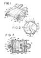
- FIG. 1is a perspective view of an electric field powered clamp-on fault indicator constructed in accordance with the invention and installed on a cable within a power distribution system with an indicator flag in the fault position.
- FIG. 2is a front view of the fault indicator of FIG. 1 showing the indicator flag reset from the fault position to show a light emitting diode indicator for indicating an overload condition in accordance with the invention.
- FIG. 3is a cross-sectional view of the fault indicator of FIGS. 1 and 2 taken along the sectional line 3 — 3 of FIG. 2 .
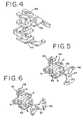
- FIG. 4is a perspective view of the assembled magnetic actuator of the indicator flag assembly.
- FIG. 5is a diagrammatic view of the principal components of the indicator flag assembly in a reset indicating position.
- FIG. 6is a diagrammatic view of the principal components of the indicator flag assembly in a fault indicating position.
- FIG. 7is a perspective view of an alternate embodiment of an electric field powered clamp-on fault indicator that is constructed in accordance with the present invention and that may be installed on a cable within a power distribution system.
- FIG. 8is a front view of the fault indicator of FIG. 7 showing an illuminated LED to indicate the occurrence of an overload condition, and an LED that is not illuminated and that may be used to indicate a fault condition.
- FIG. 9is a cross-sectional view of the fault indicator of FIGS. 7 and 8 taken along the sectional line 9 — 9 of FIG. 8
- FIG. 10is a functional block diagram of the electronic circuitry for use in the fault indicators shown in FIGS. 1-3 and 6 - 9 .
- FIG. 11is an electrical circuit diagram of the circuitry of the fault indicators shown in FIGS. 1-3 and 6 - 9 .
- FIG. 12is an example of a current profile on a monitored conductor that represents an overload condition and a timing diagram of the response of the electronic circuitry of FIG. 11 to this overload condition.
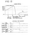
- FIG. 13is an example of a current profile on a monitored conductor that represents a fault condition and a timing diagram of the response of the electronic circuitry of FIG. 11 to this fault condition.
- FIG. 14is a flow chart illustrating typical steps that may be employed by a microprocessor during the various operational modes of the fault indicators with an overload indicator.
- a clamp-on timed reset fault indicatoris constructed in accordance with the invention.
- Fault indicator 20indicates fault currents in an electrical feeder or distribution cable, generally designated 21 , and includes a circuit module, generally designated 22 .
- circuit module 22is attached to the outer surface of the cable 21 , which may include a central conductor 25 , a concentric insulating layer 26 and an electrically grounded rubber outer sheath 27 .
- Circuit module 22includes a housing 30 (FIG. 2) that contains electronic circuitry for sensing and responding to fault currents, such as on a printed circuit board 49 . The structure and operation of this circuitry will be discussed below.
- a clamp assembly 31is suited for attaching module 22 to a monitored conductor, such as cable 21 .
- An eye 36 on an end cap 53may be provided to allow use of a conventional hotstick during installation or removal of fault indicator 20 about cable 21 .
- End cap 53forms part of the housing 30 , and may be sonically welded to housing 30 to seal the interior of fault indicator 20 against contamination.
- circuit module 22also includes a status indicating flag 40 to indicate whether a fault has occurred on cable 21 .
- the flag 40may be viewed from the exterior of fault indicator 20 through one or more generally transparent windows 41 disposed on the front of the end cap 53 of the fault indicator.
- Indicator flag 40includes two indicator segments on either side of the axis of rotation which preferably each extend less than 90 degrees around the axis of rotation. Thus, when in the reset condition, such as in FIG. 2, no portion of indicator flag 40 is visible through windows 41 .
- windows 41may also extend into the sides of end cap 53 for better viewing of indicator flag 40 .
- indicator flag 40is positioned by circuitry in circuit module 22 to be out of view.
- portions 54 of end cap 53are generally opaque to conceal the indicator flag 40 from view when in the reset condition.
- the indicator flag 40is repositioned by the circuitry to present a red or fault-indicating surface that may be viewed through the windows 41 on the front face of module 22 .
- the red or other highly visible colored surface of indicator flag 40is only visible following occurrence of a fault.
- a partition 55may be integral to housing 30 for rotatably supporting the indicator flag assembly including flag 40 and a flag actuator magnet 58 .
- End cap 53may be provided with a pivot point 57 for flag 40 to rotate about a generally horizontal axis, as seen in FIG. 3 .
- Actuation of indicator flag 40 between reset and fault indicating positionsis accomplished by flag actuator magnet 58 which is rotatably coupled to the flag by a shaft coupled to the flag 40 .
- the shaftis maintained in alignment with the axis of the housing 30 by means of bearing surfaces disposed in partition 55 and pivot point 57 .
- Partition 55also serves as a background for the windows 41 when flag 40 is in the reset position, and partition 55 may, for example, have a white surface to differentiate or contrast from the red color of flag 40 to clearly indicate a reset condition.
- Flag actuator magnet 58(FIG. 5) is secured to and rotates with indicator flag 40 .
- Flag actuator magnet 58is formed of a magnetic material having a high coercive force, such as ceramic, and is magnetically polarized to form four magnetic poles of opposite polarity, as indicated in FIGS. 5 and 6, with like magnetic polarities along diameters of the magnet. That is, actuator magnet 58 has four poles of opposite polarity spaced at 90 degrees about the circumference of the magnet.
- a four pole piece, generally designated 59 in FIGS. 3-6is preferably formed of a magnetic material having a relatively low coercive force, such as chrome steel.
- the four poles of pole piece 59are positioned to be in magnetic communication with flag actuator magnet 58 .
- a wire winding 42is wound on a bobbin 43 of pole piece 59 .
- FIGS. 5 and 6Operation of the indicator flag assembly is illustrated in FIGS. 5 and 6.
- the indicator flag assemblymay be substantially identical in construction and operation to that described in U.S. Pat. Nos. 4,495,489 and 6,016,105.
- Actuator magnet 58 and hence indicator flag 40are biased to the position and to the magnetic polarities shown in FIG. 5 when the fault indicator 20 is in a non-trip or reset condition by means of the generally cross-shaped magnetic pole piece 59 .
- the segments of the indicator flag 40are vertically disposed as shown in FIG. 5, the flag segments are masked by the generally opaque segments 54 of the end cap 53 in FIG. 1 .
- indicator flag 40is not visible to the observer through windows 41 .
- circuitry in circuit module 22causes winding 42 of pole piece 59 to be momentarily energized which causes pole piece 59 to be remagnetized to the polarities shown in FIG. 6 .
- the poles of flag actuator magnet 58are repelled by adjacent like-polarity poles of the pole piece 59 , and the indicator flag 40 is caused to rotate 90 degrees to the indicating position shown in FIG. 6 . In this position, the red indicator segments of indicator flag 40 are visible through windows 41 and a lineman viewing the fault indicator is advised that a fault current has occurred in conductor 21 .
- the indicator flag 40remains in the fault-indicating position shown in FIG. 6 until the poles of pole piece 59 are subsequently remagnetized back to the polarity shown in FIG. 5.
- a momentary reset currentis applied to winding 42 after the lapse of a predetermined time, for example, a couple to several hours.
- the momentary reset current applied to winding 42is in an opposite direction to that applied upon detecting the fault condition.
- This reset remagnetization of pole piece 59causes flag actuator magnet 58 to again be repelled by the adjacent poles of pole piece 59 which causes actuator magnet 58 and indicator flag 40 to rotate and to resume the vertical position shown in FIG. 5 .
- fault indicator 20is reset and indicator flag 40 is no longer visible.
- Magnetic shielding for the pole piece 59 and the indicator flag assembly, including actuator magnet 58may be provided by a band 51 disposed on a significant portion of the inside circumference of the housing 30 . If band 51 is formed from brass or steel, a significant degree of magnetic shielding may be provided to the internal components.
- the fault indicator 20preferably has a timed reset to reset some hours after a fault occurs.
- fault indicators 20 and 20 a(FIGS. 7-9) continue to display the fault indicating flag 40 or a fault indicating LED 35 after a reclosing relay restores current to the main line.
- Thisenables a lineman to easily trace the fault by following the tripped fault indicators to a section of the line that has faulted. The point of the fault may then be located and repaired, or the line may be replaced.
- the length of the timed resetmay be in the range of 1 to 24 or more hours, and is preferably about 4 hours. Four hours normally provides sufficient time for a lineman or repair crew to review the tripped fault indicators to determine the part of the distribution system that has caused the fault.
- Fault indicator 20 ais an alternate embodiment of fault indicator 20 shown in FIGS. 1-3.
- Fault indicator 20 aoperates the similarly to fault indicator 20 except that fault indicator 20 a displays a fault condition by illuminating an LED 35 instead of using the electromechanical arrangement of fault indicator 20 , including flag 40 .
- both fault indicators 20 and 20 ainclude a sensor to sense an overload condition and a display, such as LED 33 in FIG. or LED 34 in FIGS. 7-9, to display the overload condition.
- LED 33 or 34may be selected from any color commercially available. However, a color that is traditionally used for a warning, such as yellow is preferred. In the embodiment shown in FIGS. 6-9 with a fault indicating LED 35 , it is preferable to have different colors for the different conditions. Since LED 35 is likely to be of a red color, it is preferable that LED 34 not also be red.
- This overload conditionis below a fault condition that would cause fault indicators 20 or 20 a to indicate a fault.
- the overload conditionmay be defined to be any load above 500 A.
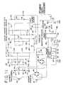
- FIG. 10A block diagram of the electronic circuitry for fault indicators 20 or 20 a is shown in FIG. 10.
- a transformer 60is disposed in an end of fault indicators 20 (FIG. 3) and 20 a (FIG. 9) in relatively close proximity to conductor 21 to derive operating power for the electronic circuitry, generally designated 100 , including that circuitry contained within blocks 62 and 63 .
- a current sensor 61which may be disposed adjacently to transformer 60 in close proximity to conductor 21 , provides a signal to circuitry block 63 that is representative of the current load in conductor 21 .
- the circuitry 100is shown in greater detail in FIG. 11.
- a pair of Zener diodes 61 and 62is arranged back-to-back, with a resistor 63 in between the Zener diodes, across the terminals of transformer 60 .
- a pair of lines 64 and 65provide the potential developed across resistor 63 to a full-wave rectification diode bridge 66 .
- Capacitors 67 - 70filter the DC voltage from bridge 66
- a voltage regulator 71provides further regulation of the voltage supplied to a microprocessor 75 .
- this power circuit for microprocessormay be designed such that microprocessor 75 begins to be powered up when the current on monitored conductor 21 is about 50 A.
- Microprocessor 75has an oscillation circuit, generally designated 73 , including a frequency crystal, to set the clock speed of the microprocessor.
- One output of microprocessor 75is connected to LED 33 or 34 through a resistor 77 , back to the supply voltage Vcc from voltage regulator 71 .
- Vccsupply voltage
- any signals developed in current sensor 61are full-wave rectified by a diode bridge 83 .
- Resistor 84 and capacitor 85filter this current sense signal before it is provided to microprocessor 75 on input line 86 .
- This portion of the electronic circuitry 100is preferably designed to cause microprocessor 75 to activate the overload indicating LED 33 or 34 when the desired overload threshold is reached, such as 600 A.
- Capacitors 93 - 95 and diodes 96 - 99operate to quadruple the voltage across transformer 60 to a voltage in the range of 40 to 70 volts. Capacitor 104 charges up toward this potential. A diode 102 keeps a negative bias of about 0.7 volts across capacitor 108 and the source to gate junction to keep FET 110 normally in a non-conductive condition. When an inrush condition occurs, some of the energy of capacitor 104 is transferred to capacitor 108 causing the source to gate of FET 110 to be forward biased. FET 110 then conducts and discharges capacitor 104 through the path consisting of resistor 107 , resistor 106 and Zener diode 105 . At this time, capacitor 103 assists in keeping a positive bias on the gate of FET 110 to keep it in conduction. The low charge on capacitor 104 , when in the inrush condition, will disable the fault sensing circuit.
- Thyristors 115 and 116are used to supply the currents necessary for the electromagnetic circuitry to set and reset indicator flag 40 in the fault indicator 20 of FIGS. 1-3.
- Such circuitryis known to the prior art.
- U.S. Pat. No. 6,016,105is incorporated by reference herein, in its entirety.
- a magnetic reed switch 45is provided in the fault sensing circuitry. As seen in FIG. 1, magnetic reed switch 45 is positioned with its axis perpendicular to and spaced from the axis of conductor 21 to respond to fault currents in the conductor in a manner well known to the art. When magnetic reed switch 45 closes upon the occurrence of a fault current, relay 90 is energized to close its contacts thereby providing a fault signal at fault terminal 89 .
- curve 150represents a profile over time of the current in a monitored conductor.
- 600 Ais the overload current threshold and 800 A is the fault trip threshold.
- microprocessorpreferably does not immediately cause LED 33 or 34 to indicate an overload condition, since such conditions may often be temporary. However, if the overload condition persists for about 20 minutes, in this example, LED 33 or 34 is activated to begin flashing at a first rate indicative of a present overload condition, as shown in the timing sequence by signal 153 changing to the on mode at time T 2 .
- the overload contact signal 155will also change to the closed mode, indicating that overload relay 79 has been activated by microprocessor 75 to cause overcurrent output 80 to provide an overload signal.
- the load currentdrops below the 600 A threshold to about 550 A before microprocessor 75 determines that the overload condition is no longer in effect.
- microprocessorcauses LED 33 or 34 to flash at a second rate, as indicated by signal 152 . This second rate of flashing may continue for about 8 hours, to indicate that an overload condition has occurred in the recent past.
- the contacts on the overload relay 79are opened and an overload signal is no longer present at output terminal 80 . Note that since the fault threshold of 800 A was never exceeded, the target signal 151 was not tripped and the fault relay 90 was not energized to provide a fault signal on fault terminal 89 .
- FIG. 13Another example is provided in FIG. 13 .
- load currentquickly rises past the overload threshold of 600 A at time T 1 to the fault threshold of 800 A at time T 3 . If the time between T 1 and T 3 is less than 20 minutes, fault indicators 20 and 20 a will go into the fault mode.
- fault indicator 20will have its flag 40 blocking view of overload indicating LED 33 .
- LED 33 or 34will not signal any overload condition, as shown in signals 152 and 153 , nor will overload relay 79 be actuated to close its contacts, as represented by signal 155 .
- the fault indicator, flag 40 or LED 35will be actuated to the fault indicating condition.
- Fault relay 90will be actuated to provide a fault signal at fault terminal 89 .
- fault indicators 40 and 35will continue to display the fault condition for a predetermined time, such as to time T 4 .
- a flow chart for microprocessor 75is shown in FIG. 14 .
- the timersare reset at block 170 .
- Decision block 171determines if the load current is less than 600 A. If yes, it returns to continue sampling the load current. If the load current is greater than 600 A, a 20 minute timer is started at block 172 . The load current is again sampled at decision block 173 . If less than 600 A, the timer is reset at block 174 and returns to the start point. If the load current is greater than 600 A, decision block 175 determines if 20 minutes has expired. If not, the load current continues to be monitored at block 173 .
- microprocessor 75turns on LED 33 or 34 at block 176 .
- LED 33 or 34is pulsed at a first faster rate, such as 3 ⁇ 4 second on, followed by 3 ⁇ 4 second off. Of course, a variety of different time intervals could be selected for the first faster rate.
- Overload relay 79is also closed to provide the overload signal at terminal 80 .
- Load currentcontinues to be monitored at block 177 to see if it has fallen below 550 A. If not, monitoring continues. If the load current is below 550 A, microprocessor 75 initiates pulsing LED 33 or 34 at a second slower rate, such as 3 ⁇ 4 second on, followed by 21 ⁇ 2 seconds off, as at block 178 .
- Microprocessor 75determines if load current again exceeds 600 A at block 179 . If so, the 20 minute timer is started again at block 180 . The load current is then monitored at block 181 . If the current falls below 600 A, the 20 minute timer is reset at block 182 and the process returns to the start position. However, if 20 minutes expires with the load current above 600 A. at block 183 , the LED 33 or 34 are again turned on at the faster rate at block 176 to indicate that the overload condition persists.
- block 184decides whether 8 hours has expired. If not, LED 33 or 34 continues to be illuminated at the slower rate, indicative of a recent overload condition. If 8 hours has expired, block 185 terminates illumination of LED 33 or 34 , clears the 8 hour timer and returns to the start position.
- fault indicator 20may be manually reset at any time.
- a reset magnetic reed switch 120is disposed in the housing 30 in FIG. 3, preferably at a generally perpendicular angle to conductor 21 . Magnetic reed switch 120 may be manually closed with a permanent magnet tool in a manner known to the art.
Landscapes
- Engineering & Computer Science (AREA)
- Power Engineering (AREA)
- Physics & Mathematics (AREA)
- General Physics & Mathematics (AREA)
- Emergency Protection Circuit Devices (AREA)
Abstract
Description
Claims (18)
Priority Applications (6)
| Application Number | Priority Date | Filing Date | Title |
|---|---|---|---|
| US10/280,328US6822576B1 (en) | 2001-10-26 | 2002-10-25 | Microprocessor controlled fault detector with circuit overload condition detection |
| US10/454,847US6949921B1 (en) | 2001-10-26 | 2003-06-04 | Auto-calibration of multiple trip settings in a fault indicator |
| US10/454,850US7023691B1 (en) | 2001-10-26 | 2003-06-04 | Fault Indicator with permanent and temporary fault indication |
| US10/454,851US6894478B1 (en) | 2001-10-26 | 2003-06-04 | Fault indicator with automatically configured trip settings |
| US10/455,670US7106048B1 (en) | 2001-10-26 | 2003-06-04 | Fault indicator with auto-configuration for overhead or underground application |
| US10/988,007US7271580B1 (en) | 2001-10-26 | 2004-11-12 | Apparatus and method for programmable trip settings in a faulted circuit indicator |
Applications Claiming Priority (2)
| Application Number | Priority Date | Filing Date | Title |
|---|---|---|---|
| US33763201P | 2001-10-26 | 2001-10-26 | |
| US10/280,328US6822576B1 (en) | 2001-10-26 | 2002-10-25 | Microprocessor controlled fault detector with circuit overload condition detection |
Related Parent Applications (2)
| Application Number | Title | Priority Date | Filing Date |
|---|---|---|---|
| US10/280,329Continuation-In-PartUS7315169B1 (en) | 2001-10-26 | 2002-10-25 | Microprocessor controlled fault indicator having inrush restraint circuit |
| US28032202AContinuation-In-Part | 2001-10-26 | 2002-10-25 |
Related Child Applications (4)
| Application Number | Title | Priority Date | Filing Date |
|---|---|---|---|
| US28019502AContinuation-In-Part | 2001-10-26 | 2002-10-25 | |
| US10/280,219Continuation-In-PartUS6734662B1 (en) | 2001-10-26 | 2002-10-25 | Microprocessor controlled fault indicator having led fault indication circuit with battery conservation mode |
| US10/280,329Continuation-In-PartUS7315169B1 (en) | 2001-10-26 | 2002-10-25 | Microprocessor controlled fault indicator having inrush restraint circuit |
| US10/454,847Continuation-In-PartUS6949921B1 (en) | 2001-10-26 | 2003-06-04 | Auto-calibration of multiple trip settings in a fault indicator |
Publications (1)
| Publication Number | Publication Date |
|---|---|
| US6822576B1true US6822576B1 (en) | 2004-11-23 |
Family
ID=33436632
Family Applications (1)
| Application Number | Title | Priority Date | Filing Date |
|---|---|---|---|
| US10/280,328Expired - LifetimeUS6822576B1 (en) | 2001-10-26 | 2002-10-25 | Microprocessor controlled fault detector with circuit overload condition detection |
Country Status (1)
| Country | Link |
|---|---|
| US (1) | US6822576B1 (en) |
Cited By (29)
| Publication number | Priority date | Publication date | Assignee | Title |
|---|---|---|---|---|
| US20050057259A1 (en)* | 2003-09-16 | 2005-03-17 | The Boeing Company | System and method for remotely detecting and locating damaged conductors in a power system |
| US20070085693A1 (en)* | 2005-10-19 | 2007-04-19 | E.O. Schweitzer Manufacturing Company, Llc | System, a tool and method for communicating with a faulted circuit indicator using a remote display |
| US20070086135A1 (en)* | 2005-10-18 | 2007-04-19 | Schweitzer Engineering Laboratories, Inc. | Method of detecting faults using graduated fault detection levels |
| US20080231463A1 (en)* | 2005-10-19 | 2008-09-25 | Feight Laurence V | System, a Tool and a Method for Communicating with a Faulted Circuit Indicator Using a Display |
| US20080312856A1 (en)* | 2007-06-15 | 2008-12-18 | Feight Laurence V | Self-Calibrating Voltage Sensor |
| US20090219163A1 (en)* | 2008-02-29 | 2009-09-03 | Feight Laurence V | Faulted circuit indicator with fault characteristic detection & display |
| US20090231150A1 (en)* | 2008-03-17 | 2009-09-17 | Feight Laurence V | Faulted circuit indicator with end-of-life display and discharge |
| US7626794B2 (en) | 2005-10-18 | 2009-12-01 | Schweitzer Engineering Laboratories, Inc. | Systems, methods, and apparatus for indicating faults within a power circuit utilizing dynamically modified inrush restraint |
| US20100176960A1 (en)* | 2008-11-21 | 2010-07-15 | Michael Bitsch | Branch current monitor with an alarm |
| US8526156B2 (en) | 2011-12-21 | 2013-09-03 | Schweitzer Engineering Laboratories Inc | High speed signaling of power system conditions |
| US8665102B2 (en) | 2008-07-18 | 2014-03-04 | Schweitzer Engineering Laboratories Inc | Transceiver interface for power system monitoring |
| US9182429B2 (en) | 2012-01-04 | 2015-11-10 | Sentient Energy, Inc. | Distribution line clamp force using DC bias on coil |
| US9229036B2 (en) | 2012-01-03 | 2016-01-05 | Sentient Energy, Inc. | Energy harvest split core design elements for ease of installation, high performance, and long term reliability |
| EP2280900A4 (en)* | 2008-05-15 | 2017-04-05 | Warn Industries, Inc. | Integrated overload and low voltage interrupt module |
| US9954354B2 (en) | 2015-01-06 | 2018-04-24 | Sentient Energy, Inc. | Methods and apparatus for mitigation of damage of power line assets from traveling electrical arcs |
| US9984818B2 (en) | 2015-12-04 | 2018-05-29 | Sentient Energy, Inc. | Current harvesting transformer with protection from high currents |
| US10161986B2 (en) | 2016-10-17 | 2018-12-25 | Schweitzer Engineering Laboratories, Inc. | Electric power system monitoring using distributed conductor-mounted devices |
| US10634733B2 (en) | 2016-11-18 | 2020-04-28 | Sentient Energy, Inc. | Overhead power line sensor |
| US11041915B2 (en) | 2018-09-18 | 2021-06-22 | Sentient Technology Holdings, LLC | Disturbance detecting current sensor |
| US11114858B2 (en) | 2019-09-16 | 2021-09-07 | Schweitzer Engineering Laboratories, Inc. | Bidirectional capacitor bank control |
| US11125832B2 (en) | 2018-12-13 | 2021-09-21 | Sentient Technology Holdings, LLC | Multi-phase simulation environment |
| US11397198B2 (en) | 2019-08-23 | 2022-07-26 | Schweitzer Engineering Laboratories, Inc. | Wireless current sensor |
| US11435403B2 (en) | 2019-09-19 | 2022-09-06 | Schweitzer Engineering Laboratories, Inc. | Determining the size of a capacitor bank |
| US11476674B2 (en) | 2018-09-18 | 2022-10-18 | Sentient Technology Holdings, LLC | Systems and methods to maximize power from multiple power line energy harvesting devices |
| US11549996B1 (en) | 2021-11-09 | 2023-01-10 | Schweitzer Engineering Laboratories, Inc. | Automatically determining the size of a capacitor bank using wireless current sensors (WCS) |
| US11567109B2 (en) | 2019-10-11 | 2023-01-31 | Schweitzer Engineering Laboratories, Inc. | Capacitor bank control using wireless electrical measurement sensors away from capacitor bank |
| US11609590B2 (en) | 2019-02-04 | 2023-03-21 | Sentient Technology Holdings, LLC | Power supply for electric utility underground equipment |
| US11750026B2 (en) | 2020-05-05 | 2023-09-05 | Novinium, Llc | System for harvesting power from a current transformer |
| US12050241B2 (en) | 2018-10-15 | 2024-07-30 | Sentient Technology Holdings, Llc. | Power line sensors with automatic phase identification |
Citations (12)
| Publication number | Priority date | Publication date | Assignee | Title |
|---|---|---|---|---|
| US3676740A (en) | 1971-06-01 | 1972-07-11 | Schweitzer Mfg Co E | Automatically resettable fault indicator |
| US3906477A (en) | 1974-09-06 | 1975-09-16 | Schweitzer Edmund O Jun | Fault indicator in test point cap |
| US4063171A (en) | 1976-11-04 | 1977-12-13 | Schweitzer Edmund O Jun | Fault indicator responsive to flow of fault current in a conductor when power flow is in one direction only |
| US4234847A (en) | 1978-11-06 | 1980-11-18 | Schweitzer Edmund O | Fault indicator |
| US4438403A (en) | 1981-08-04 | 1984-03-20 | Schweitzer Edmund O Jun | Fault indicator with combined trip and reset winding |
| US4456873A (en)* | 1981-08-04 | 1984-06-26 | Schweitzer Edmund O Jun | Cable mounted magnetic core assembly |
| US4495489A (en)* | 1982-07-20 | 1985-01-22 | Schweitzer Edmund O Jun | Fault indicator with improved flag indicator assembly |
| US4788619A (en)* | 1987-04-24 | 1988-11-29 | Basler Electric Company | Protective relays and methods |
| US5677678A (en)* | 1996-04-08 | 1997-10-14 | Schweitzer, Jr.; Edmund O. | Fault indicator having auxiliary fault sensing winding |
| US6016105A (en)* | 1998-04-30 | 2000-01-18 | E.O. Schweitzer Manufacturing Co., Inc. | Fault indicator providing contact closure and light indication on fault detection |
| US6133723A (en)* | 1998-06-29 | 2000-10-17 | E. O. Schweitzer Manufacturing Co. | Fault indicator having remote light indication of fault detection |
| US6133724A (en)* | 1998-06-29 | 2000-10-17 | E. O. Schweitzer Manufacturing Co. | Remote light indication fault indicator with a timed reset circuit and a manual reset circuit |
- 2002
- 2002-10-25USUS10/280,328patent/US6822576B1/ennot_activeExpired - Lifetime
Patent Citations (12)
| Publication number | Priority date | Publication date | Assignee | Title |
|---|---|---|---|---|
| US3676740A (en) | 1971-06-01 | 1972-07-11 | Schweitzer Mfg Co E | Automatically resettable fault indicator |
| US3906477A (en) | 1974-09-06 | 1975-09-16 | Schweitzer Edmund O Jun | Fault indicator in test point cap |
| US4063171A (en) | 1976-11-04 | 1977-12-13 | Schweitzer Edmund O Jun | Fault indicator responsive to flow of fault current in a conductor when power flow is in one direction only |
| US4234847A (en) | 1978-11-06 | 1980-11-18 | Schweitzer Edmund O | Fault indicator |
| US4438403A (en) | 1981-08-04 | 1984-03-20 | Schweitzer Edmund O Jun | Fault indicator with combined trip and reset winding |
| US4456873A (en)* | 1981-08-04 | 1984-06-26 | Schweitzer Edmund O Jun | Cable mounted magnetic core assembly |
| US4495489A (en)* | 1982-07-20 | 1985-01-22 | Schweitzer Edmund O Jun | Fault indicator with improved flag indicator assembly |
| US4788619A (en)* | 1987-04-24 | 1988-11-29 | Basler Electric Company | Protective relays and methods |
| US5677678A (en)* | 1996-04-08 | 1997-10-14 | Schweitzer, Jr.; Edmund O. | Fault indicator having auxiliary fault sensing winding |
| US6016105A (en)* | 1998-04-30 | 2000-01-18 | E.O. Schweitzer Manufacturing Co., Inc. | Fault indicator providing contact closure and light indication on fault detection |
| US6133723A (en)* | 1998-06-29 | 2000-10-17 | E. O. Schweitzer Manufacturing Co. | Fault indicator having remote light indication of fault detection |
| US6133724A (en)* | 1998-06-29 | 2000-10-17 | E. O. Schweitzer Manufacturing Co. | Remote light indication fault indicator with a timed reset circuit and a manual reset circuit |
Cited By (47)
| Publication number | Priority date | Publication date | Assignee | Title |
|---|---|---|---|---|
| US7005995B2 (en)* | 2003-09-16 | 2006-02-28 | The Boeing Company | System and method for remotely detecting and locating damaged conductors in a power system |
| US20050057259A1 (en)* | 2003-09-16 | 2005-03-17 | The Boeing Company | System and method for remotely detecting and locating damaged conductors in a power system |
| US7626794B2 (en) | 2005-10-18 | 2009-12-01 | Schweitzer Engineering Laboratories, Inc. | Systems, methods, and apparatus for indicating faults within a power circuit utilizing dynamically modified inrush restraint |
| US20070086135A1 (en)* | 2005-10-18 | 2007-04-19 | Schweitzer Engineering Laboratories, Inc. | Method of detecting faults using graduated fault detection levels |
| US8159362B2 (en) | 2005-10-18 | 2012-04-17 | Schweitzer Engineering Laboratories, Inc. | Method of detecting faults using graduated fault detection levels |
| US20070085693A1 (en)* | 2005-10-19 | 2007-04-19 | E.O. Schweitzer Manufacturing Company, Llc | System, a tool and method for communicating with a faulted circuit indicator using a remote display |
| US7382272B2 (en) | 2005-10-19 | 2008-06-03 | Schweitzer Engineering Laboratories, Inc. | System, a tool and method for communicating with a faulted circuit indicator using a remote display |
| US20080231463A1 (en)* | 2005-10-19 | 2008-09-25 | Feight Laurence V | System, a Tool and a Method for Communicating with a Faulted Circuit Indicator Using a Display |
| US7719436B2 (en) | 2005-10-19 | 2010-05-18 | Schweitzer Engineering Laboratories, Inc. | System, a tool and a method for communicating with a faulted circuit indicator using a display |
| US20080312856A1 (en)* | 2007-06-15 | 2008-12-18 | Feight Laurence V | Self-Calibrating Voltage Sensor |
| US8510066B2 (en) | 2007-06-15 | 2013-08-13 | Schweitzer Engineering Laboratories Inc | Self-calibrating voltage sensor |
| WO2009111318A1 (en)* | 2008-02-29 | 2009-09-11 | Schweitzer Engineering Laboratories, Inc. | Faulted circuit indicator with fault characteristic detection and display |
| US20090219164A1 (en)* | 2008-02-29 | 2009-09-03 | Feight Laurence V | Faulted circuit indicator with fault characteristic detection and display |
| US8159360B2 (en) | 2008-02-29 | 2012-04-17 | Schweitzer Engineering Laboratories, Inc. | Faulted circuit indicator with fault characteristic detection and display |
| US20090219163A1 (en)* | 2008-02-29 | 2009-09-03 | Feight Laurence V | Faulted circuit indicator with fault characteristic detection & display |
| US8179273B2 (en) | 2008-02-29 | 2012-05-15 | Schweitzer Engineering Laboratories, Inc. | Faulted circuit indicator with fault characteristic detection and display |
| US8274394B2 (en) | 2008-03-17 | 2012-09-25 | Schweitzer Engineering Laboratories, Inc. | Faulted circuit indicator with end-of-life display and discharge |
| US20090231150A1 (en)* | 2008-03-17 | 2009-09-17 | Feight Laurence V | Faulted circuit indicator with end-of-life display and discharge |
| EP2280900A4 (en)* | 2008-05-15 | 2017-04-05 | Warn Industries, Inc. | Integrated overload and low voltage interrupt module |
| US8665102B2 (en) | 2008-07-18 | 2014-03-04 | Schweitzer Engineering Laboratories Inc | Transceiver interface for power system monitoring |
| US8421639B2 (en)* | 2008-11-21 | 2013-04-16 | Veris Industries, Llc | Branch current monitor with an alarm |
| US20100176960A1 (en)* | 2008-11-21 | 2010-07-15 | Michael Bitsch | Branch current monitor with an alarm |
| US8526156B2 (en) | 2011-12-21 | 2013-09-03 | Schweitzer Engineering Laboratories Inc | High speed signaling of power system conditions |
| US10901008B2 (en) | 2012-01-03 | 2021-01-26 | Sentient Technology Holdings, LLC | Energy harvest split core design elements for ease of installation, high performance, and long term reliability |
| US9229036B2 (en) | 2012-01-03 | 2016-01-05 | Sentient Energy, Inc. | Energy harvest split core design elements for ease of installation, high performance, and long term reliability |
| US11789042B2 (en) | 2012-01-03 | 2023-10-17 | Sentient Technology Holdings, LLC | Energy harvest split core design elements for ease of installation, high performance, and long term reliability |
| US9182429B2 (en) | 2012-01-04 | 2015-11-10 | Sentient Energy, Inc. | Distribution line clamp force using DC bias on coil |
| US9448257B2 (en) | 2012-01-04 | 2016-09-20 | Sentient Energy, Inc. | Distribution line clamp force using DC bias on coil |
| US9954354B2 (en) | 2015-01-06 | 2018-04-24 | Sentient Energy, Inc. | Methods and apparatus for mitigation of damage of power line assets from traveling electrical arcs |
| US9984818B2 (en) | 2015-12-04 | 2018-05-29 | Sentient Energy, Inc. | Current harvesting transformer with protection from high currents |
| US10161986B2 (en) | 2016-10-17 | 2018-12-25 | Schweitzer Engineering Laboratories, Inc. | Electric power system monitoring using distributed conductor-mounted devices |
| US11442114B2 (en) | 2016-11-18 | 2022-09-13 | Sentient Technology Holdings, LLC | Overhead power line sensor |
| US10634733B2 (en) | 2016-11-18 | 2020-04-28 | Sentient Energy, Inc. | Overhead power line sensor |
| US11041915B2 (en) | 2018-09-18 | 2021-06-22 | Sentient Technology Holdings, LLC | Disturbance detecting current sensor |
| US11476674B2 (en) | 2018-09-18 | 2022-10-18 | Sentient Technology Holdings, LLC | Systems and methods to maximize power from multiple power line energy harvesting devices |
| US12050241B2 (en) | 2018-10-15 | 2024-07-30 | Sentient Technology Holdings, Llc. | Power line sensors with automatic phase identification |
| US11125832B2 (en) | 2018-12-13 | 2021-09-21 | Sentient Technology Holdings, LLC | Multi-phase simulation environment |
| US11549997B2 (en) | 2018-12-13 | 2023-01-10 | Sentient Technology Holdings, LLC | Multi-phase simulation environment |
| US11835593B2 (en) | 2018-12-13 | 2023-12-05 | Sentient Technology Holdings, LLC | Multi-phase simulation environment |
| US11947374B2 (en) | 2019-02-04 | 2024-04-02 | Sentient Technology Holdings, LLC | Power supply for electric utility underground equipment |
| US11609590B2 (en) | 2019-02-04 | 2023-03-21 | Sentient Technology Holdings, LLC | Power supply for electric utility underground equipment |
| US11397198B2 (en) | 2019-08-23 | 2022-07-26 | Schweitzer Engineering Laboratories, Inc. | Wireless current sensor |
| US11114858B2 (en) | 2019-09-16 | 2021-09-07 | Schweitzer Engineering Laboratories, Inc. | Bidirectional capacitor bank control |
| US11435403B2 (en) | 2019-09-19 | 2022-09-06 | Schweitzer Engineering Laboratories, Inc. | Determining the size of a capacitor bank |
| US11567109B2 (en) | 2019-10-11 | 2023-01-31 | Schweitzer Engineering Laboratories, Inc. | Capacitor bank control using wireless electrical measurement sensors away from capacitor bank |
| US11750026B2 (en) | 2020-05-05 | 2023-09-05 | Novinium, Llc | System for harvesting power from a current transformer |
| US11549996B1 (en) | 2021-11-09 | 2023-01-10 | Schweitzer Engineering Laboratories, Inc. | Automatically determining the size of a capacitor bank using wireless current sensors (WCS) |
Similar Documents
| Publication | Publication Date | Title |
|---|---|---|
| US6822576B1 (en) | Microprocessor controlled fault detector with circuit overload condition detection | |
| US6963197B1 (en) | Targeted timed reset fault indicator | |
| US6016105A (en) | Fault indicator providing contact closure and light indication on fault detection | |
| US6734662B1 (en) | Microprocessor controlled fault indicator having led fault indication circuit with battery conservation mode | |
| US7053601B1 (en) | Microprocessor controlled fault indicator having high visibility LED fault indication | |
| US6433698B1 (en) | Fault indicator providing light indication on fault detection | |
| US6479981B2 (en) | Remote light indication fault indicator with a timed reset circuit and a manual reset circuit | |
| CA2271537C (en) | Fault indicator having remote light indication of fault detection | |
| US4458198A (en) | Fault indicator having a remote test point at which fault occurrence is indicated by change in magnetic state | |
| US4495489A (en) | Fault indicator with improved flag indicator assembly | |
| US4438403A (en) | Fault indicator with combined trip and reset winding | |
| CA2265228C (en) | Fault indicator providing contact closure on fault detection | |
| US6894478B1 (en) | Fault indicator with automatically configured trip settings | |
| US4234847A (en) | Fault indicator | |
| US7315169B1 (en) | Microprocessor controlled fault indicator having inrush restraint circuit | |
| US5677678A (en) | Fault indicator having auxiliary fault sensing winding | |
| US6949921B1 (en) | Auto-calibration of multiple trip settings in a fault indicator | |
| US7023691B1 (en) | Fault Indicator with permanent and temporary fault indication | |
| US5220311A (en) | Direction indicating fault indicators | |
| US4686518A (en) | Fault indicator having trip inhibit circuit | |
| US4795982A (en) | Fault indicator having delayed trip circuit | |
| CA2217278C (en) | Test-point mounted fault indicator having immunity to fault currents in adjacent conductors | |
| CA1266703A (en) | Fault indicator having improved trip inhibit circuit | |
| US4375617A (en) | Fault indicator with flux concentrating means | |
| US4414543A (en) | Ground fault indicator |
Legal Events
| Date | Code | Title | Description |
|---|---|---|---|
| AS | Assignment | Owner name:E.O. SCHWEITZER MANUFACTURING COMPANY, INC., ILLIN Free format text:ASSIGNMENT OF ASSIGNORS INTEREST;ASSIGNORS:FEIGHT, LAURENCE VIRGIL;FENSKE, KURT JAMES;REEL/FRAME:015716/0500;SIGNING DATES FROM 20040727 TO 20040809 | |
| STCF | Information on status: patent grant | Free format text:PATENTED CASE | |
| AS | Assignment | Owner name:SCHWEITZER ENGINEERING LABORATORIES, INC., WASHING Free format text:MERGER;ASSIGNOR:E.O. SCHWEITZER MANUFACTURING COMPAY, LLC;REEL/FRAME:017164/0812 Effective date:20051221 | |
| FEPP | Fee payment procedure | Free format text:PAT HOLDER NO LONGER CLAIMS SMALL ENTITY STATUS, ENTITY STATUS SET TO UNDISCOUNTED (ORIGINAL EVENT CODE: STOL); ENTITY STATUS OF PATENT OWNER: LARGE ENTITY | |
| REFU | Refund | Free format text:REFUND - SURCHARGE, PETITION TO ACCEPT PYMT AFTER EXP, UNINTENTIONAL (ORIGINAL EVENT CODE: R2551); ENTITY STATUS OF PATENT OWNER: LARGE ENTITY | |
| FPAY | Fee payment | Year of fee payment:4 | |
| SULP | Surcharge for late payment | ||
| FPAY | Fee payment | Year of fee payment:8 | |
| FPAY | Fee payment | Year of fee payment:12 | |
| AS | Assignment | Owner name:CITIBANK, N.A., AS ADMINISTRATIVE AGENT, TEXAS Free format text:NOTICE OF GRANT OF SECURITY INTEREST IN PATENTS;ASSIGNOR:SCHWEITZER ENGINEERING LABORATORIES, INC.;REEL/FRAME:047231/0253 Effective date:20180601 |