US6822562B2 - Method of differentiating tires in a vehicle - Google Patents
Method of differentiating tires in a vehicleDownload PDFInfo
- Publication number
- US6822562B2 US6822562B2US10/134,032US13403202AUS6822562B2US 6822562 B2US6822562 B2US 6822562B2US 13403202 AUS13403202 AUS 13403202AUS 6822562 B2US6822562 B2US 6822562B2
- Authority
- US
- United States
- Prior art keywords
- tire
- tires
- receiver
- signal
- sensor
- Prior art date
- Legal status (The legal status is an assumption and is not a legal conclusion. Google has not performed a legal analysis and makes no representation as to the accuracy of the status listed.)
- Expired - Fee Related, expires
Links
Images

Classifications
- B—PERFORMING OPERATIONS; TRANSPORTING
- B60—VEHICLES IN GENERAL
- B60C—VEHICLE TYRES; TYRE INFLATION; TYRE CHANGING; CONNECTING VALVES TO INFLATABLE ELASTIC BODIES IN GENERAL; DEVICES OR ARRANGEMENTS RELATED TO TYRES
- B60C23/00—Devices for measuring, signalling, controlling, or distributing tyre pressure or temperature, specially adapted for mounting on vehicles; Arrangement of tyre inflating devices on vehicles, e.g. of pumps or of tanks; Tyre cooling arrangements
- B60C23/02—Signalling devices actuated by tyre pressure
- B60C23/04—Signalling devices actuated by tyre pressure mounted on the wheel or tyre
- B60C23/0408—Signalling devices actuated by tyre pressure mounted on the wheel or tyre transmitting the signals by non-mechanical means from the wheel or tyre to a vehicle body mounted receiver
- B60C23/0415—Automatically identifying wheel mounted units, e.g. after replacement or exchange of wheels
- B60C23/0416—Automatically identifying wheel mounted units, e.g. after replacement or exchange of wheels allocating a corresponding wheel position on vehicle, e.g. front/left or rear/right
Definitions
- the present inventionrelates generally to a method of differentiating tires in a vehicle including a tire pressure monitoring system by communicating tire identification information in a sensor to a receiver to identify the location of the tires.
- the front tiresgenerally are at a pressure of about 35 psi.
- the desired pressure of the rear tiresvaries depending on the load of the vehicle, but is generally in the range of 60-75 psi. As the rear tires are at a higher pressure, it is important to monitor them to ensure that the high pressure is maintained.
- Tire pressure monitoring systemshave been employed to monitor the pressure in the tires.
- the vehicle operatoris alerted when a sensor in the tire detects that the pressure in the tire drops below a predetermined level.
- Each sensorincludes an electronic code identifier.
- the sensordetects that the pressure in the tire drops below the predetermined level, the sensor sends a signal to a receiver, displaying the electronic code identifier and alerting the operator of the problem.
- a drawback to this prior systemis that even if the identity of the problem tire is known, the location of the problem tire is not as the electronic code identifier only identifies the tire, not the tire location. Commonly, after being alerted to a problem, the operator determines the location of the problem tire by manual inspection.
- each tireincludes a sensor which communicates with a receiver to differentiate the front tires from the rear tires.
- a flag bitis stored in the sensor.
- the rear tiresare inflated to a pressure greater than the high threshold pressure, only the rear tires have a flag bit.
- a warning algorithmis initiated to warn the driver of the low pressure condition.
- a pressure drop below the low pressure threshold in the front tireswill not initiate the warning algorithm.
- the flag bitis permanently retained in the sensor until reset by reducing the pressure in the tire to zero.
- the receiversends a RF signal to one of the RF transmitters in a tire in a known location. After receiving the signal, the RF transmitter generates a RF signal which is sent to the corresponding transceiver in the tire. As the transmitter is proximate to the transceiver, only the desired transceiver will receive the RF signal. After receiving the signal, the transceiver then sends a return signal including the identification code to the receiver. After recognizing the identification code, the receiver relates the identification code to the location. This process is repeated for each tire location to identify the tire in each location.
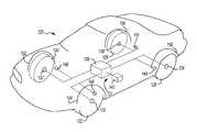
- FIG. 1illustrates a top schematic view of a first example of a tire differentiating system of the present invention
- FIG. 2illustrates a top schematic view of a second example of a tire differentiating system of the present invention.
- FIG. 1schematically illustrates a top view of a vehicle 20 including a first example of a tire differentiating system 21 which differentiates the rear tires 26 and 28 .
- the vehicle 20includes a set of front tires 22 and 24 and a set of rear tires 26 and 28 , each including a sensor 30 , 32 , 34 and 36 , respectively, and each having an identification code.
- the sensors 30 , 32 , 34 and 36communicate with a receiver 38 powered by an external energy source 40 .
- the external energy source 40is a battery.
- the rear tires 26 and 28are inflated to a pressure greater than the pressure of the front tires 22 and 24 .
- the front tires 22 and 24are inflated to 35 psi
- the rear tires 26 and 28are inflated to a pressure between 60 psi and 75 psi.
- the pressure of the rear tires 26 and 28varies as the load of the vehicle 20 varies. Although specific pressures are described, it is to be understood other pressures can be employed.
- the tires 26 and 28When the tires 26 and 28 are inflated to a pressure above a high threshold pressure, a flag bit is triggered and stored in the respective sensors 34 and 36 , and the identification code is communicated to the receiver 38 .
- the receiver 38then associates the identification codes of the tires 26 and 28 with the flag bits as rear tires.
- the high threshold pressureis greater than the pressure of the front tires 22 and 24 , and therefore only the rear tires 26 and 28 will have a flag bit retained in the sensor 34 and 36 .
- the high threshold pressureis between 40 and 50 psi.
- the sensors 34 and 36communicate with the receiver 38 and which identifies the tires 26 and 28 as rear tires.
- the flag bit in the sensors 34 and 36is triggered by the receiver 38 , which then associates the flag bit with rear tires 34 and 36 .
- a warning algorithmis initiated to warn the driver of the low pressure condition.
- the low pressure thresholdis 25 psi. Only a drop in pressure in the tires with a flag bit will initiate the warning algorithm. As the front tires 22 and 24 never reach a pressure great enough to trigger the flag bit, a pressure drop below the low pressure threshold in the front tires 22 and 24 will not initiate the warning algorithm 42 .
- the warning algorithmgenerates a warning signal 42 which indicates to the driver that the pressure in the rear tires 26 and 28 has dropped below the low pressure threshold.
- the warning signal 42can be audio or visual, such as a flashing or solid light in the vehicle cab.
- the warning algorithmcan be generated either if there is a rapid or a gradual change in pressure the tires rear 26 or 28 .
- the flag bitis permanently retained in the sensors 34 and 36 . If the tires 22 , 24 , 26 and 28 are rotated, the flag bits in the sensors 34 and 36 must be reset. Preferably, the sensors 34 and 36 are reset by reducing the pressure in the rear tires 26 and 28 to zero. Once the sensors 34 and 36 sense zero pressure and are reset, the sensors 30 , 32 , 34 and 36 can re-learn the type of tire the sensors 30 , 32 , 34 and 36 are mounted in.
- FIG. 2illustrates a second example of a tire differentiating system 121 employing a tire pressure monitoring system.
- Each tire 122 , 124 , 126 and 128 on the vehicle 120includes a respective transceiver 130 , 132 , 134 and 136 with a RF detector circuit.
- Each transceiver 130 , 132 , 134 and 136includes an identification code and information regarding tire size, material, and rim size.
- a RF transmitter 144 , 146 , 148 and 150 having an antennais located in the wheel well 152 , 154 , 156 and 158 proximate to each of the respective transceivers 130 , 132 , 134 and 136 .
- the RF transmitters 144 , 146 , 148 and 150communicate with a receiver 138 which is powered by an external energy source 140 , such as a battery.
- the receiver 138sends a signal to a RF transmitter 144 in a known location, such as the front driver's wheel well 152 .
- the RF transmitter 144After receiving the signal, the RF transmitter 144 generates a RF signal which is received by the transceiver 130 .
- the transceiver 130After receiving the RF signal, the transceiver 130 then sends a return signal including the identification code to the receiver 138 .
- the receiver 138then relates the identification code of the tire 122 with the front driver's wheel well 152 .
- the RF signal from the RF transmitter 144will only be received by the desired transceiver 130 and will be not received by the other transceivers 132 , 134 and 136 , reducing identification errors. Therefore, when a signal is sent to a specific RF transmitter 144 , 146 , 148 and 150 , only the transceiver 130 , 132 , 134 and 136 , respectively, associated with that RF transmitter 144 , 146 , 148 and 150 , respectively, will respond.
- the receiver 138can determine which tire 130 , 132 , 134 and 136 is in each wheel well 152 , 154 , 156 and 158 .
- the receiver 138sends a signal to the RF transmitter 146 in the front passenger's wheel well 154 .
- the RF transmitter 146sends a signal to the transceiver 132 , which sends a return signal to the receiver 138 with the identification code of the front passenger tire 124 .
- the receiver 138then interrogates the remaining transceivers 134 and 136 to determine the identification codes associated with the tires 126 and 128 in these wheel wells 156 and 158 .
- the tire differentiating system 121can be employed to locate a specific tire 122 , 124 , 126 and 128 and then report to the receiver 138 where the specific tire 122 , 124 , 126 and 128 is located.
- the receiver 138sends a signal to each RF transmitter 130 , 132 , 134 , and 136 , searching for a specific identification code.
- the receiver 138determines where the specific tire 122 , 124 , 126 and 128 is located.
- the transceivers 144 , 146 , 148 and 150are activated only when the receiver 138 sends a signal, increasing the life of the external energy source 140 .
- the external energy source 140can further be increased by decreasing the number of times the transceivers 144 , 146 , 148 and 150 are interrogated and by controlling the rate of information reporting. Additionally, if the tires are rotated, the receiver 138 can re-learn the position of each tire 130 , 132 , 134 and 136 by repeating the interrogation process.
Landscapes
- Engineering & Computer Science (AREA)
- Mechanical Engineering (AREA)
- Arrangements For Transmission Of Measured Signals (AREA)
- Measuring Fluid Pressure (AREA)
Abstract
Description
Claims (6)
Priority Applications (1)
| Application Number | Priority Date | Filing Date | Title |
|---|---|---|---|
| US10/134,032US6822562B2 (en) | 2001-04-26 | 2002-04-26 | Method of differentiating tires in a vehicle |
Applications Claiming Priority (3)
| Application Number | Priority Date | Filing Date | Title |
|---|---|---|---|
| US28686801P | 2001-04-26 | 2001-04-26 | |
| US34102701P | 2001-10-30 | 2001-10-30 | |
| US10/134,032US6822562B2 (en) | 2001-04-26 | 2002-04-26 | Method of differentiating tires in a vehicle |
Publications (2)
| Publication Number | Publication Date |
|---|---|
| US20020196137A1 US20020196137A1 (en) | 2002-12-26 |
| US6822562B2true US6822562B2 (en) | 2004-11-23 |
Family
ID=26964113
Family Applications (1)
| Application Number | Title | Priority Date | Filing Date |
|---|---|---|---|
| US10/134,032Expired - Fee RelatedUS6822562B2 (en) | 2001-04-26 | 2002-04-26 | Method of differentiating tires in a vehicle |
Country Status (3)
| Country | Link |
|---|---|
| US (1) | US6822562B2 (en) |
| EP (1) | EP1289780A1 (en) |
| WO (1) | WO2002087905A1 (en) |
Cited By (2)
| Publication number | Priority date | Publication date | Assignee | Title |
|---|---|---|---|---|
| US20040243352A1 (en)* | 2001-09-13 | 2004-12-02 | Akio Morozumi | Data collection method |
| US20100073208A1 (en)* | 2008-09-25 | 2010-03-25 | Udo Karthaus | Apparatus and method for the calibration of delta-sigma modulators |
Families Citing this family (5)
| Publication number | Priority date | Publication date | Assignee | Title |
|---|---|---|---|---|
| US8266465B2 (en) | 2000-07-26 | 2012-09-11 | Bridgestone Americas Tire Operation, LLC | System for conserving battery life in a battery operated device |
| US7161476B2 (en) | 2000-07-26 | 2007-01-09 | Bridgestone Firestone North American Tire, Llc | Electronic tire management system |
| JP2004299448A (en)* | 2003-03-28 | 2004-10-28 | Pacific Ind Co Ltd | Receiver for tire condition monitoring device and tire condition monitoring device |
| GB2427497B (en)* | 2005-06-23 | 2009-08-05 | Ford Global Tech Llc | Motor vehicle equipped with a tyre pressure monitoring system |
| JP5359233B2 (en)* | 2008-12-08 | 2013-12-04 | 横浜ゴム株式会社 | Tire condition monitoring method and monitoring system |
Citations (13)
| Publication number | Priority date | Publication date | Assignee | Title |
|---|---|---|---|---|
| US4301442A (en) | 1980-09-24 | 1981-11-17 | Croissant Robert E | Vehicular anti-theft device |
| US4450431A (en)* | 1981-05-26 | 1984-05-22 | Hochstein Peter A | Condition monitoring system (tire pressure) |
| WO1988009976A1 (en) | 1987-06-02 | 1988-12-15 | Christoph Breit | Device for protecting the systems and load of motor vehicles |
| DE19652365C1 (en) | 1996-12-17 | 1998-04-02 | Albert Thorp Gmbh | Tyre identifying method for road vehicle |
| US5900808A (en) | 1997-02-21 | 1999-05-04 | Lebo; Michael E. | Low pressure warning system |
| EP0933236A1 (en) | 1998-02-02 | 1999-08-04 | Tien-Tsai Huang | Apparatus for detecting pressure condition in a pneumatic tyre |
| US6018993A (en) | 1995-11-17 | 2000-02-01 | Doduco Gmbh | Method for monitoring tire pressure |
| US6034596A (en) | 1998-09-15 | 2000-03-07 | Smith; Julian | Motor vehicle tire pressure and temperature sensing system |
| US6369703B1 (en)* | 2000-06-30 | 2002-04-09 | Eaton Corporation | Tire pressure monitor and location identification system |
| US6414592B1 (en)* | 2001-01-02 | 2002-07-02 | Trw Inc. | Tire condition sensor communication with tire location provided via manually inputted update |
| US6441728B1 (en)* | 2001-01-02 | 2002-08-27 | Trw Inc. | Tire condition sensor communication with tire location provided via vehicle-mounted identification units |
| US6489888B1 (en)* | 2001-06-29 | 2002-12-03 | Johnson Controls Technology Company | Using signal strength to identify tire position |
| US6518876B1 (en)* | 2000-04-25 | 2003-02-11 | Schrader-Bridgeport International, Inc. | Determination of wheel sensor position using radio frequency detectors in an automotive remote tire monitor system |
- 2002
- 2002-04-26EPEP02731534Apatent/EP1289780A1/ennot_activeWithdrawn
- 2002-04-26USUS10/134,032patent/US6822562B2/ennot_activeExpired - Fee Related
- 2002-04-26WOPCT/US2002/013297patent/WO2002087905A1/ennot_activeApplication Discontinuation
Patent Citations (14)
| Publication number | Priority date | Publication date | Assignee | Title |
|---|---|---|---|---|
| US4301442A (en) | 1980-09-24 | 1981-11-17 | Croissant Robert E | Vehicular anti-theft device |
| US4450431A (en)* | 1981-05-26 | 1984-05-22 | Hochstein Peter A | Condition monitoring system (tire pressure) |
| WO1988009976A1 (en) | 1987-06-02 | 1988-12-15 | Christoph Breit | Device for protecting the systems and load of motor vehicles |
| EP0373170A1 (en) | 1987-06-02 | 1990-06-20 | Christoph Breit | Device for protecting the systems and load of motor vehicles. |
| US6018993A (en) | 1995-11-17 | 2000-02-01 | Doduco Gmbh | Method for monitoring tire pressure |
| DE19652365C1 (en) | 1996-12-17 | 1998-04-02 | Albert Thorp Gmbh | Tyre identifying method for road vehicle |
| US5900808A (en) | 1997-02-21 | 1999-05-04 | Lebo; Michael E. | Low pressure warning system |
| EP0933236A1 (en) | 1998-02-02 | 1999-08-04 | Tien-Tsai Huang | Apparatus for detecting pressure condition in a pneumatic tyre |
| US6034596A (en) | 1998-09-15 | 2000-03-07 | Smith; Julian | Motor vehicle tire pressure and temperature sensing system |
| US6518876B1 (en)* | 2000-04-25 | 2003-02-11 | Schrader-Bridgeport International, Inc. | Determination of wheel sensor position using radio frequency detectors in an automotive remote tire monitor system |
| US6369703B1 (en)* | 2000-06-30 | 2002-04-09 | Eaton Corporation | Tire pressure monitor and location identification system |
| US6414592B1 (en)* | 2001-01-02 | 2002-07-02 | Trw Inc. | Tire condition sensor communication with tire location provided via manually inputted update |
| US6441728B1 (en)* | 2001-01-02 | 2002-08-27 | Trw Inc. | Tire condition sensor communication with tire location provided via vehicle-mounted identification units |
| US6489888B1 (en)* | 2001-06-29 | 2002-12-03 | Johnson Controls Technology Company | Using signal strength to identify tire position |
Non-Patent Citations (2)
| Title |
|---|
| PCT International Search Report for Application No. PCT/US02/13297 dated Aug. 13, 2002. |
| Smartire Systems, Inc., "Wireless Pressure Monitor System", Owner's Manual, 1998, pps 42-46; printed in Canada. |
Cited By (4)
| Publication number | Priority date | Publication date | Assignee | Title |
|---|---|---|---|---|
| US20040243352A1 (en)* | 2001-09-13 | 2004-12-02 | Akio Morozumi | Data collection method |
| US6978217B2 (en)* | 2001-09-13 | 2005-12-20 | T&D Corporation | Data collection method and devices therefor |
| US20100073208A1 (en)* | 2008-09-25 | 2010-03-25 | Udo Karthaus | Apparatus and method for the calibration of delta-sigma modulators |
| US8179294B2 (en)* | 2008-09-25 | 2012-05-15 | Ubidyne, Inc. | Apparatus and method for the calibration of delta-sigma modulators |
Also Published As
| Publication number | Publication date |
|---|---|
| EP1289780A1 (en) | 2003-03-12 |
| WO2002087905A1 (en) | 2002-11-07 |
| US20020196137A1 (en) | 2002-12-26 |
Similar Documents
| Publication | Publication Date | Title |
|---|---|---|
| EP1388439B1 (en) | A Method and system for preventing false alarms in a tyre pressure monitoring system | |
| JP4213580B2 (en) | System and method for monitoring automobile tire pressure | |
| US6828905B2 (en) | System for monitoring and for signaling by radio the pressure in pneumatic tires on motor vehicles | |
| EP1419908B1 (en) | Method and apparatus for associating tires with tire locations of a vehicle | |
| US7239948B2 (en) | Tyre pressure monitoring system | |
| US8144023B2 (en) | Tire inflation pressure detecting apparatus capable of triggering only selected transceiver to perform task | |
| US20030107481A1 (en) | Tire condition monitoring apparatus and method | |
| US8106758B2 (en) | Tire localization system | |
| US20060090558A1 (en) | Tire wear sensor | |
| JP2005138826A (en) | Method and system for reporting theft and towing of vehicle | |
| CN101505979A (en) | Method and apparatus for determining identifiable tire position location in a tire pressure monitoring system | |
| EP2287018A1 (en) | Vehicle tire monitoring system and method | |
| US6998974B2 (en) | Method and system for monitoring the wheels of motor vehicle | |
| CN103112321A (en) | Tire monitoring system based on radio frequency identification technology | |
| US20090184814A1 (en) | Wireless tire pressure monitoring system with interactive multiple frequency channel | |
| US20040193340A1 (en) | Tire status monitoring apparatus | |
| US6822562B2 (en) | Method of differentiating tires in a vehicle | |
| EP1359029B1 (en) | System and method for tire inflation monitoring system | |
| US6999861B2 (en) | Tire status monitoring apparatus and receiver therefor | |
| US20040140887A1 (en) | System and method of facilitating training of a tire pressure monitoring system on a vehicle | |
| US6897769B2 (en) | Tire pressure monitoring system and method for registering identification code in the same | |
| US6810727B1 (en) | Tire pressure monitoring system algorithm for dual placard applications | |
| US20050109092A1 (en) | System and method for determining tire position | |
| GB2382205A (en) | System for detecting theft of vehicle wheels | |
| US20050109093A1 (en) | System and method for detecting low tire pressure |
Legal Events
| Date | Code | Title | Description |
|---|---|---|---|
| AS | Assignment | Owner name:SIEMENS VDO AUTOMOTIVE CORPORATION, MICHIGAN Free format text:ASSIGNMENT OF ASSIGNORS INTEREST;ASSIGNORS:POIRIER, JAMES ANTHONY;O'CONNOR, STEVE;REEL/FRAME:013214/0566;SIGNING DATES FROM 20020531 TO 20020801 | |
| FEPP | Fee payment procedure | Free format text:PAYER NUMBER DE-ASSIGNED (ORIGINAL EVENT CODE: RMPN); ENTITY STATUS OF PATENT OWNER: LARGE ENTITY Free format text:PAYOR NUMBER ASSIGNED (ORIGINAL EVENT CODE: ASPN); ENTITY STATUS OF PATENT OWNER: LARGE ENTITY | |
| FPAY | Fee payment | Year of fee payment:4 | |
| FPAY | Fee payment | Year of fee payment:8 | |
| AS | Assignment | Owner name:CONTINENTAL AUTOMOTIVE SYSTEMS US, INC., MICHIGAN Free format text:CHANGE OF NAME;ASSIGNOR:SIEMENS VDO AUTOMOTIVE CORPORATION;REEL/FRAME:034979/0865 Effective date:20071203 | |
| AS | Assignment | Owner name:CONTINENTAL AUTOMOTIVE SYSTEMS, INC., MICHIGAN Free format text:MERGER;ASSIGNOR:CONTINENTAL AUTOMOTIVE SYSTEMS US, INC.;REEL/FRAME:035091/0577 Effective date:20121212 | |
| REMI | Maintenance fee reminder mailed | ||
| LAPS | Lapse for failure to pay maintenance fees | ||
| STCH | Information on status: patent discontinuation | Free format text:PATENT EXPIRED DUE TO NONPAYMENT OF MAINTENANCE FEES UNDER 37 CFR 1.362 | |
| FP | Lapsed due to failure to pay maintenance fee | Effective date:20161123 |