US6822225B2 - Pulsed discharge ionization source for miniature ion mobility spectrometers - Google Patents
Pulsed discharge ionization source for miniature ion mobility spectrometersDownload PDFInfo
- Publication number
- US6822225B2 US6822225B2US10/254,749US25474902AUS6822225B2US 6822225 B2US6822225 B2US 6822225B2US 25474902 AUS25474902 AUS 25474902AUS 6822225 B2US6822225 B2US 6822225B2
- Authority
- US
- United States
- Prior art keywords
- chamber
- drift
- corona discharge
- ions
- ion
- Prior art date
- Legal status (The legal status is an assumption and is not a legal conclusion. Google has not performed a legal analysis and makes no representation as to the accuracy of the status listed.)
- Expired - Lifetime, expires
Links
Images


Classifications
- H—ELECTRICITY
- H01—ELECTRIC ELEMENTS
- H01J—ELECTRIC DISCHARGE TUBES OR DISCHARGE LAMPS
- H01J49/00—Particle spectrometers or separator tubes
- H01J49/02—Details
- H01J49/10—Ion sources; Ion guns
- H01J49/16—Ion sources; Ion guns using surface ionisation, e.g. field-, thermionic- or photo-emission
- H01J49/168—Ion sources; Ion guns using surface ionisation, e.g. field-, thermionic- or photo-emission field ionisation, e.g. corona discharge
- G—PHYSICS
- G01—MEASURING; TESTING
- G01N—INVESTIGATING OR ANALYSING MATERIALS BY DETERMINING THEIR CHEMICAL OR PHYSICAL PROPERTIES
- G01N27/00—Investigating or analysing materials by the use of electric, electrochemical, or magnetic means
- G01N27/62—Investigating or analysing materials by the use of electric, electrochemical, or magnetic means by investigating the ionisation of gases, e.g. aerosols; by investigating electric discharges, e.g. emission of cathode
- G01N27/622—Ion mobility spectrometry
Definitions
- IMSIon mobility spectrometry
- VOCschemical warfare agents
- CW agentschemical warfare agents
- IMSion mobility spectrometry
- IMSion mobility spectrometry
- Explosivesgenerally have high electron affinities and drugs and chemical warfare (CW) agents have high proton affinities.
- IMSion mobility spectrometer
- negative and positive ions of these sampleswill be preferentially formed.
- IMSion mobility spectrometer
- Some commercial ion mobility spectrometersare available for detecting the above chemicals.
- a typical problem for commercial hand-held IMSis loss of sensitivity.
- the sensitivity of a desktop size IMS detector now used in airportsis about 1 nanogram for explosives.
- the sensitivity of a smaller, handheld versionwould be reduced more than 100 times.
- the main reason for the reduced sensitivityis the use of a nickel-63 (Ni 63 ) radioactive source for ionization.
- Nickel-63emits electrons with 67 keV kinetic energy.
- the low stopping power of the high-energy electrons in gasesgenerates less ions in the small volume of the miniature IMS ionization chamber, resulting in the low sensitivity.
- a nickel-63 sourcehas potential hazards due to its radioactive nature.
- pulses with various polarities, amplitudes, and widthsare generated by a RF oscillator and are used to produce ions through a corona discharge. Certain features of these pulses are undefined, which tends to limit the performance of this kind of spectrometer.
- An ion gateis used to control ions entering an ion mobility channel and the electronics require that the device have extra size.
- the inventionis a method and apparatus for providing a pulsed discharge ionization source particularly designed for miniature ion mobility spectrometers (IMS), but also usable in other analytical instruments.
- the inventionuses a pulse to generate a corona around a tip of non-radioactive (non-doped) material to generate ions from a sample gas and to signal the start of ion motion.
- the applied potentialcomprises a pulse component and a dc base voltage component, which reduces the pulse component. This reduces noise and power consumption.
- Miniaturized ion mobility spectrometers equipped with the pulsed discharge ionization source of the present inventionhave the following advantages: (1) high sensitivity because the ions are concentrated in a very small volume, (2) the use of an ion gate and its associated electronics is unnecessary, and (3) a high dynamic range is available because the ionization rate can be adjusted.
- the present inventionprovides a method and an apparatus in which ions are generated in a highly confined space and time, which results in high sensitivity for miniature IMS detectors.
- a processor-based electronic controlenables timing of the initial ion motion with the ionization pulse. This provides a device without the need for an ion extract gate for ions entering a drift chamber. This reduces the size of the drift chamber body, the electronics control package, and power consumption.
- the inventionalso provides for increased dynamic range by adjusting the pulse height or by adjusting the DC bias.
- FIG. 1is a schematic view of a first embodiment of an apparatus for practicing the method of the present invention
- FIG. 2is a schematic view of a second embodiment of an apparatus for practicing the method of the present invention.
- FIG. 3is a graph of ion detection current vs. time vs. dc bias voltage
- FIG. 4is a graph of ion detection current vs. drift time for moist air and for nitrogen supplied to the drift chamber;
- FIG. 5is a graph of arcing threshold voltage vs. distance between two electrodes for generating an ion-producing corona
- FIG. 6is a graph of arcing threshold voltage vs. pulse height for generating an ion-producing corona.
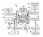
- the present inventionis practiced in a miniature ion mobility spectrometer (IMS) 10 employing a pulsed corona discharge ion source as shown in FIG. 1 .
- IMSion mobility spectrometer
- FIG. 2shows a second miniaturized embodiment of the apparatus featuring a microelectronic CPU 51 .
- the devicehas a cylindrical body 11 comprised of ten ( 10 ) stacked, annular metal electrodes 12 - 19 , 22 and 23 which are separated by annular spacers 21 (5-mm thick and 8 mm ID) of a dielectric material such as Teflon.
- Thisforms a drift channel 24 which can be in the range from 1.7 mm-2.5 mm in diameter and 35-50 mm in effective length. In FIG. 1, the drift channel is specifically 2.5 mm in diameter and 47 mm in length, respectively.
- the first electrode 12is biased with a power supply 20 to provide an ion drift voltage, with the voltage being distributed to the intermediate electrodes 13 - 19 , 22 and 23 through these resistors.
- the last electrode 23is connected to an electrical ground 40 .
- the next to the last electrode 22is connected to a 470-pf capacitor 39 to suppress transients.
- An ion detector electrode 25is located in the drift chamber 24 between the last electrode 23 and the next to last electrode 22 . Positive or negative potentials can be applied to the detection electrode 25 for detecting positive and negative ions, respectively.
- a nickel-tipped electrode 26 of non-radioactive (non-doped) material with an end radius of curvature of approximately 25 ⁇ mis mounted at the entrance of the drift chamber 24 .
- the second drift channel electrode 13is used as the counter electrode for corona discharge with the distance to the tip 26 being larger than the threshold distance for discharge zone as illustrated in FIG. 5 .
- the corona-producing tip 26together with the second electrode 13 of the IMS channel, formed a tip-ring corona discharge element.
- a sample gasis supplied from reservoir 38 in FIG. 1 through a flow meter 37 to an inlet into the corona discharge end of the drift chamber 24 .
- a carrier gasin this case, nitrogen, is supplied from a source 35 through a filter 34 and a second flow meter 33 to an inlet into the detection end of the drift chamber 24 .
- These gasesexit the drift chamber through valve 41 and outlet 42 .
- a sample gasis received from a source 43 , while dry air enters from a supply 53 into an entrance at the opposite end of the drift chamber 24 .
- the dry airincludes both drift gas and reactant gas. All of these gases exit from exit 42 .
- a coronais produced at the electrode 26 by applying an electrical pulse having a width of from 40 ns to 100 ⁇ s, a pulse height varying from 0.2-3.3 kV and a repetition rate (frequency) of 20 Hz.
- the pulseis generated as a base dc voltage component originating at a high voltage source 36 and a varying pulse component generated by a pulse generator comprising high voltage source 29 , amplifier 28 and pulse generator 27 , which generates pulses on the order of 5 volts before they are amplified. These pulses are summed with a base dc voltage through capacitor C 1 .
- the resulting amplified high-voltage pulseis applied to the corona tip electrode 26 , which is seen in FIG. 1 .
- ionsare generated in the vicinity of the tip 26 . After the pulse, the ions move along the drift channel 24 through the carrier gases under the influence of the drift field bias provided by voltage supply 20 .
- the corona discharge pulsealso provides a start signal for timing the ion mobility movements. For each pulse, ions are separated according to their travel time to reach the ion detector 25 located at the end of the channel 24 . There, an ion current is produced and is transmitted to a current amplifier 30 connected to electrode 25 . The time difference between the start signal and arrival of ions is detected by a time-to-digital converter (TDC) 31 and is transmitted to a computer 32 for analysis. If a digital oscilloscope 31 is used instead of time-to-digital converter 31 , the start pulse triggers the oscilloscope. The ion arrival signal is recorded by the scope and sent to the computer 32 .
- TDCtime-to-digital converter
- the detector 25is connected to an amplifier 30 in FIG. 1 which amplifies the signals.
- the oscilloscopeis connected to an Apple Macintosh computer 32 running a Labview application program in FIG. 1 . This is a lab prototype embodiment for demonstrating the operation of the invention. In FIG. 2, the components in FIG. 1 are designed for reduced size in a commercial embodiment.
- Ion mobility spectra of both positive and negative ionswere measured as a function of pulse width. For positive ions, the ion current increased with pulse width and saturated. For negative ions, the ion current peaked rapidly and then decayed with increased pulse width.
- Ion mobility spectra of negative ions produced by pulsed corona discharge and by ionization of airwere measured as a function of drift bias voltage from ⁇ 600 VDC to ⁇ 1700 VDC as seen in FIG. 3 .
- the pulseshad 1.08 ⁇ s width and +2600V amplitude.
- the sample airwas at atmospheric pressure and room temperature.
- the drift gaswas N 2 , which was fed from a source 35 through a filter 34 and flow meter 33 at the detector end of the IMS channel 24 with a flow rate of 20 sccm (standard cubic centimeter per minute).
- FIG. 4A typical mobility spectrum of positive ions generated by pulsed corona discharge ionization of air is shown in FIG. 4 .
- the pulse potential applied to the tip 26was also positive, the same polarity as used for generating negative ions, with a height of 3100 VDC and a width of 14.5 ⁇ s.
- the corona discharge propertiesdepend on the distance between the tip 26 and the counter electrode 13 .
- the counter electrodecan be either a ring or a tip. This is illustrated in FIG. 5 .
- a threshold of potentialabout 1900 VDC was reached.
- spark breakdownoccurred, which preceded the establishment of a stable corona.
- the voltage thresholdwas found to increase as a function of distance, as shown in FIG. 5, up to 2400 volts at 1.96 mm. Stable corona discharge conditions could not be found in this distance range.
- corona dischargeoccurred at a threshold that was a function of the drift bias.
- Corona dischargewas also generated by a combination of a base dc potential in combination with a pulsed voltage potential.
- a dc voltage supply 36is connected to a dc pulse generator 27 , an amplifier 28 and a second dc supply 29 through capacitor C 1 .
- dc voltage supply 45is connected to a pulse amplifier 47 and a pulse height control circuit 48 through a capacitor 46 .
- the pulseis commanded by the microelectronic CPU 51 through a digital-to-analog converter 49 .
- the base dc potentialwhich varied from 0 to 3000 volts, was superimposed on the pulsed potential.
- the combined potentialspermit independent variation of the dc potential, pulse height, and pulse width to the corona tip.
- the ion mobility spectrum currentcan be measured as a function of dc bias voltage.
- the currentexhibited a threshold for the dc bias and increased to a saturation level.
- the dc thresholdwas found to linearly decrease from 3000 VDC to 200 VDC as the pulse height was increased from 200 VDC to 3000 VDC, as shown in FIG. 6 . Therefore, ions could be generated with lower voltage pulses if the dc base voltage were raised.
- the detector 25 in FIG. 2is connected in close proximity to an amplifier 44 which amplified the small signal.
- This signalis then digitized by digitizer 50 to filter noise, and is then read by the microelectronic CPU 51 .
- thresholdsare set, and if a threshold is exceeded, a visual indication is provided to a user through an alarm display 52 , such as by illuminating an icon or changing the color of an object on a display screen.
- the electronic circuits 20 and 44 - 52 in FIG. 2can be made quite compact and can be mounted on circuit boards. These can be packaged with the drift chamber body 11 in a package the size of a lightweight notebook computer of the type having a titanium case.
- the pulsed corona ionization source of the present inventioneliminates the need for the ion gate of the prior art near the ion source. It also provides for a smaller drift chamber and a smaller body for housing the drift chamber. The invention also provides a method for timing the movement of the ions between the source and the detector. The use of a dc voltage comprising a pulse element and a base voltage element reduces the pulse component, which reduces noise and power consumption.
Landscapes
- Physics & Mathematics (AREA)
- Chemical & Material Sciences (AREA)
- Analytical Chemistry (AREA)
- Plasma & Fusion (AREA)
- Engineering & Computer Science (AREA)
- Biochemistry (AREA)
- Life Sciences & Earth Sciences (AREA)
- Health & Medical Sciences (AREA)
- Electrochemistry (AREA)
- General Health & Medical Sciences (AREA)
- General Physics & Mathematics (AREA)
- Immunology (AREA)
- Pathology (AREA)
- Chemical Kinetics & Catalysis (AREA)
- Spectroscopy & Molecular Physics (AREA)
- Other Investigation Or Analysis Of Materials By Electrical Means (AREA)
- Electron Tubes For Measurement (AREA)
Abstract
Description
Claims (16)
Priority Applications (6)
| Application Number | Priority Date | Filing Date | Title |
|---|---|---|---|
| US10/254,749US6822225B2 (en) | 2002-09-25 | 2002-09-25 | Pulsed discharge ionization source for miniature ion mobility spectrometers |
| CA002500171ACA2500171A1 (en) | 2002-09-25 | 2003-09-10 | Pulsed discharge ionization source for miniature ion mobility spectrometers |
| JP2004569412AJP4522866B2 (en) | 2002-09-25 | 2003-09-10 | A pulsed discharge ion source for a compact ion mobility spectrometer. |
| PCT/US2003/028269WO2004081556A2 (en) | 2002-09-25 | 2003-09-10 | Pulsed discharge ionization source for miniature ion mobility spectrometers |
| EP03816115.4AEP1546699B1 (en) | 2002-09-25 | 2003-09-10 | Pulsed discharge ionization source for miniature ion mobility spectrometers |
| AU2003303952AAU2003303952A1 (en) | 2002-09-25 | 2003-09-10 | Pulsed discharge ionization source for miniature ion mobility spectrometers |
Applications Claiming Priority (1)
| Application Number | Priority Date | Filing Date | Title |
|---|---|---|---|
| US10/254,749US6822225B2 (en) | 2002-09-25 | 2002-09-25 | Pulsed discharge ionization source for miniature ion mobility spectrometers |
Publications (2)
| Publication Number | Publication Date |
|---|---|
| US20040164238A1 US20040164238A1 (en) | 2004-08-26 |
| US6822225B2true US6822225B2 (en) | 2004-11-23 |
Family
ID=32867829
Family Applications (1)
| Application Number | Title | Priority Date | Filing Date |
|---|---|---|---|
| US10/254,749Expired - LifetimeUS6822225B2 (en) | 2002-09-25 | 2002-09-25 | Pulsed discharge ionization source for miniature ion mobility spectrometers |
Country Status (6)
| Country | Link |
|---|---|
| US (1) | US6822225B2 (en) |
| EP (1) | EP1546699B1 (en) |
| JP (1) | JP4522866B2 (en) |
| AU (1) | AU2003303952A1 (en) |
| CA (1) | CA2500171A1 (en) |
| WO (1) | WO2004081556A2 (en) |
Cited By (21)
| Publication number | Priority date | Publication date | Assignee | Title |
|---|---|---|---|---|
| US7429731B1 (en) | 2005-05-05 | 2008-09-30 | Science Applications International Corporation | Method and device for non-contact sampling and detection |
| US20090050799A1 (en)* | 2007-08-24 | 2009-02-26 | Carter Roger G | Transition molding |
| US7569812B1 (en) | 2003-05-30 | 2009-08-04 | Science Applications International Corporation | Remote reagent ion generator |
| US7568401B1 (en) | 2005-06-20 | 2009-08-04 | Science Applications International Corporation | Sample tube holder |
| US7576322B2 (en) | 2005-11-08 | 2009-08-18 | Science Applications International Corporation | Non-contact detector system with plasma ion source |
| US20110068264A1 (en)* | 2009-09-23 | 2011-03-24 | Jun Xu | Ion mobility sensor system |
| US8008617B1 (en) | 2007-12-28 | 2011-08-30 | Science Applications International Corporation | Ion transfer device |
| US20110265653A1 (en)* | 2008-11-26 | 2011-11-03 | Eads Deutschland Gmbh | Device for collecting particles that have a strong electron affinity |
| US8071957B1 (en) | 2009-03-10 | 2011-12-06 | Science Applications International Corporation | Soft chemical ionization source |
| US8123396B1 (en) | 2007-05-16 | 2012-02-28 | Science Applications International Corporation | Method and means for precision mixing |
| US8525111B1 (en) | 2012-12-31 | 2013-09-03 | 908 Devices Inc. | High pressure mass spectrometry systems and methods |
| US8816272B1 (en) | 2014-05-02 | 2014-08-26 | 908 Devices Inc. | High pressure mass spectrometry systems and methods |
| US8878127B2 (en) | 2013-03-15 | 2014-11-04 | The University Of North Carolina Of Chapel Hill | Miniature charged particle trap with elongated trapping region for mass spectrometry |
| US8921774B1 (en) | 2014-05-02 | 2014-12-30 | 908 Devices Inc. | High pressure mass spectrometry systems and methods |
| US9093253B2 (en) | 2012-12-31 | 2015-07-28 | 908 Devices Inc. | High pressure mass spectrometry systems and methods |
| US9099286B2 (en) | 2012-12-31 | 2015-08-04 | 908 Devices Inc. | Compact mass spectrometer |
| CN105632872A (en)* | 2016-03-11 | 2016-06-01 | 北京理工大学 | Novel corona discharge-based ion mobility spectrometry device |
| US9502226B2 (en) | 2014-01-14 | 2016-11-22 | 908 Devices Inc. | Sample collection in compact mass spectrometry systems |
| US9711341B2 (en) | 2014-06-10 | 2017-07-18 | The University Of North Carolina At Chapel Hill | Mass spectrometry systems with convective flow of buffer gas for enhanced signals and related methods |
| US10242857B2 (en) | 2017-08-31 | 2019-03-26 | The University Of North Carolina At Chapel Hill | Ion traps with Y-directional ion manipulation for mass spectrometry and related mass spectrometry systems and methods |
| KR20230164774A (en)* | 2015-07-30 | 2023-12-04 | 스미스 디텍션-워트포드 리미티드 | Apparatus And Methods For Ion Separation, Especially IMS, Using An Ion Sutter |
Families Citing this family (56)
| Publication number | Priority date | Publication date | Assignee | Title |
|---|---|---|---|---|
| US7940716B2 (en) | 2005-07-01 | 2011-05-10 | Terahop Networks, Inc. | Maintaining information facilitating deterministic network routing |
| US7142107B2 (en) | 2004-05-27 | 2006-11-28 | Lawrence Kates | Wireless sensor unit |
| US8033479B2 (en) | 2004-10-06 | 2011-10-11 | Lawrence Kates | Electronically-controlled register vent for zone heating and cooling |
| GB0501940D0 (en)* | 2005-01-29 | 2005-03-09 | Smiths Group Plc | Analytical apparatus |
| GB0612042D0 (en)* | 2006-06-19 | 2006-07-26 | Owlstone Ltd | Pulsed flow ion mobility spectrometer |
| CN106885838B (en)* | 2007-02-05 | 2021-01-12 | 卓漂仪谱公司 | Ion mobility spectrometer and method |
| WO2009151877A2 (en) | 2008-05-16 | 2009-12-17 | Terahop Networks, Inc. | Systems and apparatus for securing a container |
| DE102008029555A1 (en)* | 2008-06-21 | 2010-01-14 | Dräger Safety AG & Co. KGaA | Method for determining charged analytes in sample gas to be examined using ion mobility spectrometer, involves selecting analytes according to recombination characteristics by temporal distance between ionization and transferring processes |
| US8754775B2 (en) | 2009-03-20 | 2014-06-17 | Nest Labs, Inc. | Use of optical reflectance proximity detector for nuisance mitigation in smoke alarms |
| DE102009051069A1 (en)* | 2009-10-28 | 2011-05-05 | Drägerwerk AG & Co. KGaA | Gas detector and method for monitoring the concentration of a gas |
| US8918219B2 (en) | 2010-11-19 | 2014-12-23 | Google Inc. | User friendly interface for control unit |
| US9104211B2 (en) | 2010-11-19 | 2015-08-11 | Google Inc. | Temperature controller with model-based time to target calculation and display |
| US8727611B2 (en) | 2010-11-19 | 2014-05-20 | Nest Labs, Inc. | System and method for integrating sensors in thermostats |
| US8850348B2 (en) | 2010-12-31 | 2014-09-30 | Google Inc. | Dynamic device-associated feedback indicative of responsible device usage |
| US9268344B2 (en) | 2010-11-19 | 2016-02-23 | Google Inc. | Installation of thermostat powered by rechargeable battery |
| US9448567B2 (en) | 2010-11-19 | 2016-09-20 | Google Inc. | Power management in single circuit HVAC systems and in multiple circuit HVAC systems |
| US9046898B2 (en) | 2011-02-24 | 2015-06-02 | Google Inc. | Power-preserving communications architecture with long-polling persistent cloud channel for wireless network-connected thermostat |
| US9092039B2 (en) | 2010-11-19 | 2015-07-28 | Google Inc. | HVAC controller with user-friendly installation features with wire insertion detection |
| US9453655B2 (en) | 2011-10-07 | 2016-09-27 | Google Inc. | Methods and graphical user interfaces for reporting performance information for an HVAC system controlled by a self-programming network-connected thermostat |
| US9459018B2 (en) | 2010-11-19 | 2016-10-04 | Google Inc. | Systems and methods for energy-efficient control of an energy-consuming system |
| US11334034B2 (en) | 2010-11-19 | 2022-05-17 | Google Llc | Energy efficiency promoting schedule learning algorithms for intelligent thermostat |
| US10346275B2 (en) | 2010-11-19 | 2019-07-09 | Google Llc | Attributing causation for energy usage and setpoint changes with a network-connected thermostat |
| US8195313B1 (en) | 2010-11-19 | 2012-06-05 | Nest Labs, Inc. | Thermostat user interface |
| US9075419B2 (en) | 2010-11-19 | 2015-07-07 | Google Inc. | Systems and methods for a graphical user interface of a controller for an energy-consuming system having spatially related discrete display elements |
| US9256230B2 (en) | 2010-11-19 | 2016-02-09 | Google Inc. | HVAC schedule establishment in an intelligent, network-connected thermostat |
| CN107065961B (en) | 2010-12-31 | 2020-06-16 | 谷歌有限责任公司 | Flexible functional partitioning of intelligent thermostat controlled HVAC systems |
| WO2012092622A2 (en) | 2010-12-31 | 2012-07-05 | Nest Labs, Inc. | Inhibiting deleterious control coupling in an enclosure having multiple hvac regions |
| US8944338B2 (en) | 2011-02-24 | 2015-02-03 | Google Inc. | Thermostat with self-configuring connections to facilitate do-it-yourself installation |
| RU2601231C2 (en)* | 2011-06-16 | 2016-10-27 | Смитс Детекшен Монреаль Инк. | Looped ionisation source |
| US8893032B2 (en) | 2012-03-29 | 2014-11-18 | Google Inc. | User interfaces for HVAC schedule display and modification on smartphone or other space-limited touchscreen device |
| CA3044757C (en) | 2011-10-21 | 2021-11-09 | Google Llc | User-friendly, network connected learning thermostat and related systems and methods |
| CN106440187A (en) | 2011-10-21 | 2017-02-22 | 谷歌公司 | Energy efficiency promoting schedule learning algorithms for intelligent thermostat |
| WO2013144679A2 (en)* | 2011-11-16 | 2013-10-03 | Owlstone Limited | Corona ionization device and method |
| US10026600B2 (en) | 2011-11-16 | 2018-07-17 | Owlstone Medical Limited | Corona ionization apparatus and method |
| EP2791962A4 (en)* | 2011-12-14 | 2015-12-09 | Waters Technologies Corp | Atmospheric pressure chemical ionization detection |
| CN106288191B (en) | 2012-03-29 | 2020-08-25 | 谷歌有限责任公司 | Processing and reporting usage information for a network-connected thermostat-controlled HVAC system |
| US9208676B2 (en) | 2013-03-14 | 2015-12-08 | Google Inc. | Devices, methods, and associated information processing for security in a smart-sensored home |
| US8659302B1 (en) | 2012-09-21 | 2014-02-25 | Nest Labs, Inc. | Monitoring and recoverable protection of thermostat switching circuitry |
| PL2898321T3 (en)* | 2012-09-21 | 2020-02-28 | Smiths Detection-Watford Limited | Cleaning of corona dischage ion source |
| US9581342B2 (en) | 2014-03-28 | 2017-02-28 | Google Inc. | Mounting stand for multi-sensing environmental control device |
| US9609462B2 (en) | 2014-03-28 | 2017-03-28 | Google Inc. | Facilitating radio frequency communications among environmental control system components |
| US9791839B2 (en) | 2014-03-28 | 2017-10-17 | Google Inc. | User-relocatable self-learning environmental control device capable of adapting previous learnings to current location in controlled environment |
| US9568201B2 (en) | 2014-03-28 | 2017-02-14 | Google Inc. | Environmental control system retrofittable with multiple types of boiler-based heating systems |
| US9612031B2 (en) | 2015-01-07 | 2017-04-04 | Google Inc. | Thermostat switching circuitry robust against anomalous HVAC control line conditions |
| CN105655228B (en)* | 2015-12-31 | 2017-07-28 | 同方威视技术股份有限公司 | A corona discharge assembly, ion mobility spectrometer and corona discharge method |
| US9607819B1 (en)* | 2016-02-03 | 2017-03-28 | The Charles Stark Draper Laboratory Inc. | Non-radioactive, capacitive discharge plasma ion source and method |
| JP6972519B2 (en)* | 2016-08-05 | 2021-11-24 | 株式会社リコー | Ion detector |
| CN106783506B (en)* | 2016-12-08 | 2018-05-11 | 中国科学院合肥物质科学研究院 | It is a kind of to utilize dipulse, the ionic migration spectrometer and detection method of the voltage-controlled ion gate processed of Asymmetric Electric |
| CN106783504B (en)* | 2016-12-26 | 2018-12-28 | 同方威视技术股份有限公司 | Ionic migration spectrometer |
| CN110770577A (en)* | 2017-07-04 | 2020-02-07 | 株式会社岛津制作所 | Ion Mobility Analyzer |
| CN107941897B (en)* | 2017-11-30 | 2024-01-02 | 北京市北分仪器技术有限责任公司 | Bipolar controllable pulse corona discharge ionization source and ion mobility spectrometer thereof |
| US10992175B2 (en) | 2018-06-15 | 2021-04-27 | Google Llc | Communication circuit for 2-wire protocols between HVAC systems and smart-home devices |
| US11020042B2 (en)* | 2019-05-15 | 2021-06-01 | Know Biological, Inc. | Seizure detection device |
| CN110289203B (en)* | 2019-06-03 | 2021-03-09 | 清华大学深圳研究生院 | Corona discharge ionization source structure and ion mobility spectrometer |
| DE102019125482B4 (en)* | 2019-09-23 | 2023-02-09 | Gottfried Wilhelm Leibniz Universität Hannover | Ion-mobility spectrometer |
| JP2023150632A (en)* | 2022-03-31 | 2023-10-16 | シャープ株式会社 | IMS analyzer and IMS analysis method |
Citations (6)
| Publication number | Priority date | Publication date | Assignee | Title |
|---|---|---|---|---|
| US4283291A (en)* | 1977-01-24 | 1981-08-11 | Union Carbide Corporation | Corona reaction method and apparatus |
| WO1993011554A1 (en) | 1991-12-03 | 1993-06-10 | Graseby Dynamics Limited | Corona discharge ionisation source |
| US5304797A (en)* | 1992-02-27 | 1994-04-19 | Hitachi, Ltd. | Gas analyzer for determining impurity concentration of highly-purified gas |
| US5405781A (en)* | 1993-09-21 | 1995-04-11 | Barringer Research Limited | Ion mobility spectrometer apparatus and method, incorporating air drying |
| US5789745A (en)* | 1997-10-28 | 1998-08-04 | Sandia Corporation | Ion mobility spectrometer using frequency-domain separation |
| US6225623B1 (en) | 1996-02-02 | 2001-05-01 | Graseby Dynamics Limited | Corona discharge ion source for analytical instruments |
Family Cites Families (5)
| Publication number | Priority date | Publication date | Assignee | Title |
|---|---|---|---|---|
| US5371364A (en)* | 1993-02-18 | 1994-12-06 | Thermo King Corporation | Practical implementations for ion mobility sensor |
| IL115984A (en)* | 1995-11-14 | 1998-08-16 | Yeda Res & Dev | Low-vacuum mass spectrometer |
| DE60141455D1 (en)* | 2000-03-14 | 2010-04-15 | Ca Nat Research Council | FAIMS APPARATUS AND METHOD USING A CARRIER GAS OF MIXED COMPOSITION |
| US6690005B2 (en)* | 2000-08-02 | 2004-02-10 | General Electric Company | Ion mobility spectrometer |
| GB0107311D0 (en)* | 2001-03-23 | 2001-05-16 | Secr Defence | Corona ionisation source |
- 2002
- 2002-09-25USUS10/254,749patent/US6822225B2/ennot_activeExpired - Lifetime
- 2003
- 2003-09-10EPEP03816115.4Apatent/EP1546699B1/ennot_activeExpired - Lifetime
- 2003-09-10WOPCT/US2003/028269patent/WO2004081556A2/enactiveApplication Filing
- 2003-09-10CACA002500171Apatent/CA2500171A1/ennot_activeAbandoned
- 2003-09-10JPJP2004569412Apatent/JP4522866B2/ennot_activeExpired - Lifetime
- 2003-09-10AUAU2003303952Apatent/AU2003303952A1/ennot_activeAbandoned
Patent Citations (7)
| Publication number | Priority date | Publication date | Assignee | Title |
|---|---|---|---|---|
| US4283291A (en)* | 1977-01-24 | 1981-08-11 | Union Carbide Corporation | Corona reaction method and apparatus |
| WO1993011554A1 (en) | 1991-12-03 | 1993-06-10 | Graseby Dynamics Limited | Corona discharge ionisation source |
| US5684300A (en) | 1991-12-03 | 1997-11-04 | Taylor; Stephen John | Corona discharge ionization source |
| US5304797A (en)* | 1992-02-27 | 1994-04-19 | Hitachi, Ltd. | Gas analyzer for determining impurity concentration of highly-purified gas |
| US5405781A (en)* | 1993-09-21 | 1995-04-11 | Barringer Research Limited | Ion mobility spectrometer apparatus and method, incorporating air drying |
| US6225623B1 (en) | 1996-02-02 | 2001-05-01 | Graseby Dynamics Limited | Corona discharge ion source for analytical instruments |
| US5789745A (en)* | 1997-10-28 | 1998-08-04 | Sandia Corporation | Ion mobility spectrometer using frequency-domain separation |
Cited By (34)
| Publication number | Priority date | Publication date | Assignee | Title |
|---|---|---|---|---|
| US7569812B1 (en) | 2003-05-30 | 2009-08-04 | Science Applications International Corporation | Remote reagent ion generator |
| US7586092B1 (en) | 2005-05-05 | 2009-09-08 | Science Applications International Corporation | Method and device for non-contact sampling and detection |
| US7429731B1 (en) | 2005-05-05 | 2008-09-30 | Science Applications International Corporation | Method and device for non-contact sampling and detection |
| US7568401B1 (en) | 2005-06-20 | 2009-08-04 | Science Applications International Corporation | Sample tube holder |
| US7576322B2 (en) | 2005-11-08 | 2009-08-18 | Science Applications International Corporation | Non-contact detector system with plasma ion source |
| US8123396B1 (en) | 2007-05-16 | 2012-02-28 | Science Applications International Corporation | Method and means for precision mixing |
| US8308339B2 (en) | 2007-05-16 | 2012-11-13 | Science Applications International Corporation | Method and means for precision mixing |
| US20090050799A1 (en)* | 2007-08-24 | 2009-02-26 | Carter Roger G | Transition molding |
| US7709787B2 (en) | 2007-08-24 | 2010-05-04 | The United States Of America As Represented By The Secretary Of The Department Of Commerce | Stepped electric field detector |
| US8008617B1 (en) | 2007-12-28 | 2011-08-30 | Science Applications International Corporation | Ion transfer device |
| US8852325B2 (en)* | 2008-11-26 | 2014-10-07 | Eads Deutschland Gmbh | Device for collecting particles that have a strong electron affinity |
| US20110265653A1 (en)* | 2008-11-26 | 2011-11-03 | Eads Deutschland Gmbh | Device for collecting particles that have a strong electron affinity |
| US8071957B1 (en) | 2009-03-10 | 2011-12-06 | Science Applications International Corporation | Soft chemical ionization source |
| US8357893B2 (en) | 2009-09-23 | 2013-01-22 | Ut-Battelle, Llc | Ion mobility sensor system |
| US20110068264A1 (en)* | 2009-09-23 | 2011-03-24 | Jun Xu | Ion mobility sensor system |
| US9093253B2 (en) | 2012-12-31 | 2015-07-28 | 908 Devices Inc. | High pressure mass spectrometry systems and methods |
| US8525111B1 (en) | 2012-12-31 | 2013-09-03 | 908 Devices Inc. | High pressure mass spectrometry systems and methods |
| US9099286B2 (en) | 2012-12-31 | 2015-08-04 | 908 Devices Inc. | Compact mass spectrometer |
| US9252005B2 (en) | 2013-03-15 | 2016-02-02 | The University Of North Carolina At Chapel Hill | Miniature charged particle trap with elongated trapping region for mass spectrometry |
| US8878127B2 (en) | 2013-03-15 | 2014-11-04 | The University Of North Carolina Of Chapel Hill | Miniature charged particle trap with elongated trapping region for mass spectrometry |
| US11158496B2 (en) | 2013-03-15 | 2021-10-26 | The University Of North Carolina At Chapel Hill | Miniature charged particle trap with elongated trapping region for mass spectrometry |
| US10141178B2 (en) | 2013-03-15 | 2018-11-27 | The University Of North Carolina At Chapel Hill | Miniature charged particle trap with elongated trapping region for mass spectrometry |
| US9978574B2 (en) | 2014-01-14 | 2018-05-22 | 908 Devices Inc. | Sample collection in compact mass spectrometry systems |
| US9502226B2 (en) | 2014-01-14 | 2016-11-22 | 908 Devices Inc. | Sample collection in compact mass spectrometry systems |
| US10204775B2 (en) | 2014-05-02 | 2019-02-12 | 908 Devices Inc. | High pressure mass spectrometry systems and methods |
| US8921774B1 (en) | 2014-05-02 | 2014-12-30 | 908 Devices Inc. | High pressure mass spectrometry systems and methods |
| US8816272B1 (en) | 2014-05-02 | 2014-08-26 | 908 Devices Inc. | High pressure mass spectrometry systems and methods |
| US9711341B2 (en) | 2014-06-10 | 2017-07-18 | The University Of North Carolina At Chapel Hill | Mass spectrometry systems with convective flow of buffer gas for enhanced signals and related methods |
| US10068759B2 (en) | 2014-06-10 | 2018-09-04 | The University Of North Carolina At Chapel Hill | Mass spectrometry systems with convective flow of buffer gas for enhanced signals and related methods |
| KR20230164774A (en)* | 2015-07-30 | 2023-12-04 | 스미스 디텍션-워트포드 리미티드 | Apparatus And Methods For Ion Separation, Especially IMS, Using An Ion Sutter |
| CN105632872A (en)* | 2016-03-11 | 2016-06-01 | 北京理工大学 | Novel corona discharge-based ion mobility spectrometry device |
| US10242857B2 (en) | 2017-08-31 | 2019-03-26 | The University Of North Carolina At Chapel Hill | Ion traps with Y-directional ion manipulation for mass spectrometry and related mass spectrometry systems and methods |
| US10937640B2 (en) | 2017-08-31 | 2021-03-02 | The University Of North Carolina At Chapel Hill | Ion traps with y-directional ion manipulation for mass spectrometry and related mass spectrometry systems and methods |
| US12014915B2 (en) | 2017-08-31 | 2024-06-18 | The University Of North Carolina At Chapel Hill | Ion traps with y-directional ion manipulation for mass spectrometry and related mass spectrometry systems and methods |
Also Published As
| Publication number | Publication date |
|---|---|
| JP4522866B2 (en) | 2010-08-11 |
| US20040164238A1 (en) | 2004-08-26 |
| EP1546699B1 (en) | 2015-02-18 |
| WO2004081556A3 (en) | 2004-12-29 |
| CA2500171A1 (en) | 2004-09-23 |
| AU2003303952A8 (en) | 2004-09-30 |
| JP2006507508A (en) | 2006-03-02 |
| WO2004081556A2 (en) | 2004-09-23 |
| AU2003303952A1 (en) | 2004-09-30 |
| EP1546699A2 (en) | 2005-06-29 |
Similar Documents
| Publication | Publication Date | Title |
|---|---|---|
| US6822225B2 (en) | Pulsed discharge ionization source for miniature ion mobility spectrometers | |
| US5684300A (en) | Corona discharge ionization source | |
| US9972482B2 (en) | Concentric APCI surface ionization ion source, ion guide, and method of use | |
| US8829913B2 (en) | Discharge ionization current detector | |
| US6831271B1 (en) | Method for separation and enrichment of isotopes in gaseous phase | |
| US7326926B2 (en) | Corona discharge ionization sources for mass spectrometric and ion mobility spectrometric analysis of gas-phase chemical species | |
| CA2076507C (en) | Simple compact ion mobility spectrometer | |
| US8797041B2 (en) | Discharge ionization current detector | |
| US7309992B2 (en) | Gas analysis method and ionisation detector for carrying out said method | |
| US20110168881A1 (en) | Plasma-based direct sampling of molecules for mass spectrometric analysis | |
| Latif et al. | Flowing atmospheric-pressure afterglow drift tube ion mobility spectrometry | |
| Drees et al. | Stepwise optimization of a Flexible Microtube Plasma (FµTP) as an ionization source for Ion Mobility Spectrometry | |
| Habib et al. | Alternating current corona discharge/atmospheric pressure chemical ionization for mass spectrometry | |
| US7026611B2 (en) | Analytical instruments, ionization sources, and ionization methods | |
| Shelley et al. | Time-resolved mass-spectral characterization of ion formation from a low-frequency, low-temperature plasma probe ambient ionization source | |
| US11692968B2 (en) | Method and apparatus for interfacing ion and molecular selecting devices with an ion counter | |
| US20170053789A1 (en) | Corona ionization apparatus and method | |
| Ismaili et al. | Analysis of liquid samples by Low-Temperature Plasma Ionization Source-ion mobility spectrometry | |
| Latif | Flowing atmospheric pressure afterglow drift tube ion mobility spectrometry evidence discrimination | |
| CN110662486A (en) | Electrode arrangement for drift tube |
Legal Events
| Date | Code | Title | Description |
|---|---|---|---|
| AS | Assignment | Owner name:UT-BATTELLE LLC, TENNESSEE Free format text:ASSIGNMENT OF ASSIGNORS INTEREST;ASSIGNORS:XU, JUN;RAMSEY, J. MICHAEL;WHITTEN, WILLIAM B.;REEL/FRAME:013337/0602 Effective date:20020919 | |
| AS | Assignment | Owner name:U.S. DEPARTMENT OF ENERGY, DISTRICT OF COLUMBIA Free format text:CONFIRMATORY LICENSE;ASSIGNOR:UT-BATTELLE, LLC;REEL/FRAME:014000/0311 Effective date:20030225 | |
| STCF | Information on status: patent grant | Free format text:PATENTED CASE | |
| CC | Certificate of correction | ||
| FEPP | Fee payment procedure | Free format text:PAYOR NUMBER ASSIGNED (ORIGINAL EVENT CODE: ASPN); ENTITY STATUS OF PATENT OWNER: SMALL ENTITY | |
| FPAY | Fee payment | Year of fee payment:4 | |
| FEPP | Fee payment procedure | Free format text:PAYER NUMBER DE-ASSIGNED (ORIGINAL EVENT CODE: RMPN); ENTITY STATUS OF PATENT OWNER: SMALL ENTITY Free format text:PAYOR NUMBER ASSIGNED (ORIGINAL EVENT CODE: ASPN); ENTITY STATUS OF PATENT OWNER: SMALL ENTITY | |
| FEPP | Fee payment procedure | Free format text:PAT HOLDER CLAIMS SMALL ENTITY STATUS, ENTITY STATUS SET TO SMALL (ORIGINAL EVENT CODE: LTOS); ENTITY STATUS OF PATENT OWNER: SMALL ENTITY | |
| FPAY | Fee payment | Year of fee payment:8 | |
| FPAY | Fee payment | Year of fee payment:12 |