US6821261B2 - Orthopedic brace having length-adjustable supports - Google Patents
Orthopedic brace having length-adjustable supportsDownload PDFInfo
- Publication number
- US6821261B2 US6821261B2US10/020,319US2031901AUS6821261B2US 6821261 B2US6821261 B2US 6821261B2US 2031901 AUS2031901 AUS 2031901AUS 6821261 B2US6821261 B2US 6821261B2
- Authority
- US
- United States
- Prior art keywords
- channel
- support
- upright
- brace
- supports
- Prior art date
- Legal status (The legal status is an assumption and is not a legal conclusion. Google has not performed a legal analysis and makes no representation as to the accuracy of the status listed.)
- Expired - Lifetime, expires
Links
Images


Classifications
- A—HUMAN NECESSITIES
- A61—MEDICAL OR VETERINARY SCIENCE; HYGIENE
- A61F—FILTERS IMPLANTABLE INTO BLOOD VESSELS; PROSTHESES; DEVICES PROVIDING PATENCY TO, OR PREVENTING COLLAPSING OF, TUBULAR STRUCTURES OF THE BODY, e.g. STENTS; ORTHOPAEDIC, NURSING OR CONTRACEPTIVE DEVICES; FOMENTATION; TREATMENT OR PROTECTION OF EYES OR EARS; BANDAGES, DRESSINGS OR ABSORBENT PADS; FIRST-AID KITS
- A61F5/00—Orthopaedic methods or devices for non-surgical treatment of bones or joints; Nursing devices ; Anti-rape devices
- A61F5/01—Orthopaedic devices, e.g. long-term immobilising or pressure directing devices for treating broken or deformed bones such as splints, casts or braces
- A61F5/0102—Orthopaedic devices, e.g. long-term immobilising or pressure directing devices for treating broken or deformed bones such as splints, casts or braces specially adapted for correcting deformities of the limbs or for supporting them; Ortheses, e.g. with articulations
- A61F5/0123—Orthopaedic devices, e.g. long-term immobilising or pressure directing devices for treating broken or deformed bones such as splints, casts or braces specially adapted for correcting deformities of the limbs or for supporting them; Ortheses, e.g. with articulations for the knees
- A61F5/0125—Orthopaedic devices, e.g. long-term immobilising or pressure directing devices for treating broken or deformed bones such as splints, casts or braces specially adapted for correcting deformities of the limbs or for supporting them; Ortheses, e.g. with articulations for the knees the device articulating around a single pivot-point
- A—HUMAN NECESSITIES
- A61—MEDICAL OR VETERINARY SCIENCE; HYGIENE
- A61F—FILTERS IMPLANTABLE INTO BLOOD VESSELS; PROSTHESES; DEVICES PROVIDING PATENCY TO, OR PREVENTING COLLAPSING OF, TUBULAR STRUCTURES OF THE BODY, e.g. STENTS; ORTHOPAEDIC, NURSING OR CONTRACEPTIVE DEVICES; FOMENTATION; TREATMENT OR PROTECTION OF EYES OR EARS; BANDAGES, DRESSINGS OR ABSORBENT PADS; FIRST-AID KITS
- A61F5/00—Orthopaedic methods or devices for non-surgical treatment of bones or joints; Nursing devices ; Anti-rape devices
- A61F5/01—Orthopaedic devices, e.g. long-term immobilising or pressure directing devices for treating broken or deformed bones such as splints, casts or braces
- A61F5/0102—Orthopaedic devices, e.g. long-term immobilising or pressure directing devices for treating broken or deformed bones such as splints, casts or braces specially adapted for correcting deformities of the limbs or for supporting them; Ortheses, e.g. with articulations
- A61F5/0123—Orthopaedic devices, e.g. long-term immobilising or pressure directing devices for treating broken or deformed bones such as splints, casts or braces specially adapted for correcting deformities of the limbs or for supporting them; Ortheses, e.g. with articulations for the knees
- A—HUMAN NECESSITIES
- A61—MEDICAL OR VETERINARY SCIENCE; HYGIENE
- A61F—FILTERS IMPLANTABLE INTO BLOOD VESSELS; PROSTHESES; DEVICES PROVIDING PATENCY TO, OR PREVENTING COLLAPSING OF, TUBULAR STRUCTURES OF THE BODY, e.g. STENTS; ORTHOPAEDIC, NURSING OR CONTRACEPTIVE DEVICES; FOMENTATION; TREATMENT OR PROTECTION OF EYES OR EARS; BANDAGES, DRESSINGS OR ABSORBENT PADS; FIRST-AID KITS
- A61F5/00—Orthopaedic methods or devices for non-surgical treatment of bones or joints; Nursing devices ; Anti-rape devices
- A61F5/01—Orthopaedic devices, e.g. long-term immobilising or pressure directing devices for treating broken or deformed bones such as splints, casts or braces
- A61F5/0102—Orthopaedic devices, e.g. long-term immobilising or pressure directing devices for treating broken or deformed bones such as splints, casts or braces specially adapted for correcting deformities of the limbs or for supporting them; Ortheses, e.g. with articulations
- A61F2005/0132—Additional features of the articulation
- A61F2005/0172—Additional features of the articulation with cushions
- A61F2005/0174—Additional features of the articulation with cushions laterally placed
Definitions
- the present inventionrelates to orthopedic braces and, more particularly, to orthopedic braces having length adjustment capability.
- Orthopedic bracesare commonly employed after surgery or for treatment of injury to a joint. Such braces generally serve to stabilize the joint. In certain cases orthopedic braces limit joint flexion and/or extension in a controllable and adjustable manner to prevent re-injury of the joint and to promote rehabilitation.
- Some prior art orthopedic bracesinclude length-adjustable support members. However, these braces typically comprise sidebar components that are merely sandwiched together. This configuration makes them susceptible to prying forces that tend to separate the components.
- bracesuse threaded fasteners to connect the sidebar components. Adjusting these braces requires a screwdriver or turning a manual thumbscrew, both of which are inconvenient and time consuming. Such braces are also typically prone to failure due to stripped fastener threads. Other braces rely upon friction, as from tightening a lead screw, to hold the components of the brace in the desired position. These braces, however, do not provide a positive lock, and are thus prone to disadvantageous slippage.
- bracesuse an all-aluminum construction. Machining and forming aluminum, however, is relatively expensive and has certain physical limitations. Aluminum thus limits the range of features and style that may be incorporated into the brace.
- the preferred embodiments of the orthopedic bracehave several features, no single one of which is solely responsible for their desirable attributes. Without limiting the scope of this orthopedic brace as expressed by the claims that follow, its more prominent features will now be discussed briefly. However, not all of the following features are necessary to achieve the advantages of the orthopedic brace. Therefore, none of the following features should be viewed as limiting. After considering this discussion, and particularly after reading the section entitled “Detailed Description of the Preferred Embodiments,” one will understand how the features of the preferred embodiments provide advantages over prior braces. One such advantage is length adjustability so that the amount of restraint offered by the brace may be altered during a course of treatment and so that one brace may fit differently sized patients.
- the braceincludes a low profile that prevents the brace from snagging objects as the wearer moves about.
- the bracemay be manufactured from a combination of thermoplastic composite and metal that enables the brace to harness the advantages of both materials. Further, the brace may have a length adjustment mechanism that is recessed to prevent accidental activation.
- One preferred embodiment of the orthopedic bracecomprises a first support, a second support, and a hinge assembly rotatably connecting the first and second supports. At least one of the first and second supports comprises an outer portion defining a longitudinal channel and a telescoping upright movable in the channel to adjust a length of the support.
- At least one strapis provided to wrap around the brace and a patient's leg to secure the brace to the leg.
- At least one padded cuffis disposed between the patient's leg and the brace to increase patient comfort.
- the uprightis removable from the at least one of the first and second supports to shorten the overall length of the brace.
- a plurality of engagement surfacesare provided along a length of the telescoping upright, and the outer portion includes an engagement member selectively engageable with the engagement surfaces to lock the telescoping portion in place in the channel.
- the engagement memberis recessed within the upright when the engagement member engages one of the engagement surfaces.
- the engagement membercomprises a button disposed within a recess in the channel and biased toward a configuration wherein a portion of the button protrudes from a surface of the channel.
- the buttonhas an oval shape in plan aspect.
- the engagement surfacescomprise holes.
- the holeshave an oval shape in plan aspect.
- first and second supportsare curved about an axis that is parallel to a longitudinal axis of the brace.
- a cross-section of the first and second supportsincludes a first region having a first radius of curvature and a second region having a second radius of curvature longer than the first radius of curvature.
- the first regionis located between the second region and a third region having the second radius of curvature.
- first and second supportsfurther comprise at least a first generally D-shaped ring on a first side and a second generally D-shaped ring on a second side opposite the first side.
- first and second ringsare adjacent the hinge assembly.
- the uprightcomprises at least a first generally D-shaped ring on a first side and a second generally D-shaped ring on a second side opposite the first side.
- first and second ringsare located at an end of the upright opposite the hinge assembly.
- the hinge assemblycomprises flexion-limiting stops.
- the hinge assemblycomprises extension-limiting stops.
- the orthopedic bracecomprises a first support, a second support, and a hinge assembly rotatably connecting the first and second supports.
- At least one of the first and second supportscomprises a first portion constructed of a thermoplastic composite and a second portion constructed of a metal.
- the first portioncomprises an outer portion defining a longitudinal channel.
- the second portioncomprises a telescoping upright movable in the channel to adjust the length of the support.
- the first portionis connected to a metal hinge plate.
- the hinge plateis insert molded within the first portion.
- a portion of the hinge plateis bendable about an axis that is perpendicular to an axis of rotation of the hinge assembly.
- the orthopedic bracecomprises a first length-adjustable support and a second length-adjustable support.
- Each supportincludes a longitudinal channel and a sliding upright within the channel.
- a hinge assemblyrotatably connects the first and second supports.
- Each sliding uprightincludes a plurality of through holes, and a floor of each channel includes a spring-biased button. The button is engageable with each hole such that the button positively locks a position of the upright with respect to the channel. The upright is slidable within the channel when the button is depressed.
- each supportincludes a curvature about a longitudinal axis thereof such that substantially all of a surface of each support that faces a patient's leg contacts the leg.
- each supportfurther comprises a plurality of brackets that are adapted to receive flexible straps for securing the brace to a patient's leg.
- FIG. 1is a perspective view of a preferred embodiment of the orthopedic brace of the present invention including a right support and a left support, padded cuffs and straps;
- FIG. 2is a partially exploded perspective view of the brace and padded cuffs of FIG. 1;
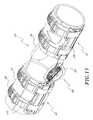
- FIG. 3is a perspective view of another preferred embodiment of the orthopedic brace including a right support;
- FIG. 4is an exploded perspective view of a calf portion of the brace of FIG. 3;
- FIG. 4Ais a partially exploded perspective view of the calf portion of FIG. 4;
- FIG. 5Ais a top plan view of a link bar of a thigh portion the brace of FIG. 3;
- FIG. 5Bis a bottom plan view of the link bar of FIG. 5A;
- FIG. 5Cis a right-side elevation view of the link bar of FIG. 5A;
- FIG. 5Dis a front elevation view of the link bar of FIG. 5A;
- FIG. 5Eis a detail view of a recess portion of the link bar of FIG. 5A;
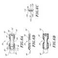
- FIG. 6Ais a top plan view of a link bar of a calf portion the brace of FIG. 3;
- FIG. 6Bis a bottom plan view of the link bar of FIG. 6A;
- FIG. 6Cis a right-side elevation view of the link bar of FIG. 6A;
- FIG. 6Dis a front elevation view of the link bar of FIG. 6A;
- FIG. 7Ais a top plan view of a hinge plate of the link bar of FIG. 5A;
- FIG. 7Bis a right-side elevation view of the hinge plate of FIG. 7A;
- FIG. 8Ais a top plan view of a hinge plate of the link bar of FIG. 6A;
- FIG. 8Bis a right-side elevation view of the hinge plate of FIG. 8A;
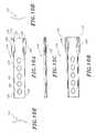
- FIG. 9Ais a top plan view of a sliding upright of a calf portion of the brace of FIG. 3;
- FIG. 9Bis a bottom plan view of the sliding upright of FIG. 9A;
- FIG. 9Cis a front elevation view of the sliding upright of FIG. 9A;
- FIG. 9Dis a right-side elevation view of the sliding upright of FIG. 9A;
- FIG. 9Eis a left-side elevation view of the sliding upright of FIG. 9A;
- FIG. 10Ais a top plan view of a sliding upright of a thigh portion of the brace of FIG. 3;
- FIG. 10Bis a bottom plan view of the sliding upright of FIG. 10A;
- FIG. 10Cis a front elevation view of the sliding upright of FIG. 10A;
- FIG. 10Dis a right-side elevation view of the sliding upright of FIG. 10A;
- FIG. 10Eis a left-side elevation view of the sliding upright of FIG. 10A;
- FIG. 11is a perspective view of a preferred embodiment of the orthopedic brace including a right support and a left support, padded cuffs and straps, wherein sliding uprights of each support have been removed; and
- FIG. 12is a partially exploded perspective view of the brace and padded cuffs of FIG. 11 .
- FIGS. 1 and 2illustrate a preferred embodiment of an orthopedic brace 20 .
- the orthopedic brace 20is a knee brace.
- certain features of the orthopedic brace 20are applicable to other types of braces as well, such as arm braces, ankle braces, neck braces, and the like.
- FIGS. 1 and 2which is adaptable for use on either the left or the right leg of a patient, comprises a first elongate support 22 for positioning along the right side of the patient's leg, and a second elongate support 24 , for positioning along the left side. If desired, only one support may be used for particular applications. In the two support configuration, however, the two supports 22 , 24 preferably are mirror images of one another.
- the supports 22 , 24are secured to a patient's leg with straps 26 that wrap around the circumference of the leg. In the embodiment illustrated in FIG. 1, six straps 26 are provided. Those of skill in the art will appreciate, however, that fewer or more straps may be used.
- a plurality of padded cuffs 28 disposed between the supports 22 , 24 and the legprovide padding and increase patient comfort. Those of skill in the art will also appreciate that the cuffs 28 merely enhance the wearability of the brace 20 , and are not an essential component of the brace 20 .
- a pad 30may be secured to an inside surface of each support 22 , 24 near a midpoint of each support 22 , 24 .
- the cuffs 28 and pads 30each comprise a layer of foam padding and a layer of a loop portion of a hook-and-loop fastener.
- an inside surface of the cuffs 28 and/or pads 30comprises a fabric.
- This surfacecontacts the patient's leg. Therefore, the fabric is preferably any material that is comfortable for wear against the skin. A preferred material is nylon.
- the cuffsneed not include a fabric layer on an inside surface. Preferably, however, the cuffs do not irritate the patient's skin.
- the loop portion of a hook-and-loop fastenerforms an outside surface of the cuffs 28 and pads 30 .
- the outside surfacecontacts a plurality of inserts 32 which may be disposed between the cuffs 28 and pads 30 and the supports 22 , 24 .
- a first face of each insertcomprises a hook portion of a hook-and-loop fastener and faces the outside surface of the cuffs 28 and pads 30 .
- the inserts 32thus removably secure the supports 22 , 24 to the cuffs 28 and pads 30 to prevent migration of the brace 20 relative to the cuffs 28 and pads 30 .
- a variety of other configurationscould be used to maintain the relative positions of the brace 20 and cuffs 28 .
- fastenersother than hook-and-loop could be used.
- the cuffscould be manufactured from neoprene, or another material that has a high coefficient of static friction.
- FIG. 3illustrates the right support 22 in detail.
- the support 22includes a thigh portion 34 and a calf portion 36 .
- a hinge portion 38rotatably connects the thigh portion 34 and calf portion 36 .
- the hinge portion 38may comprise any of a variety of well-known hinges. However, examples of preferred hinge types are described in U.S. Pat. Nos. 5,921,946 to Tillinghast, and 5,443,444 to Pruyssers, the entirety of which are incorporated herein by reference.
- FIG. 4is an exploded perspective view of the calf portion 36 of the right support 22 .
- the thigh portion 34is substantially identical to the calf portion 36 , with a few exceptions.
- the calf portion 36preferably comprises a link bar 39 , a sliding upright 40 , and a button 42 . When assembled, the button 42 nests inside the link bar 39 , as described below.
- the link bar 39in turn is constructed of two pieces, as shown in FIGS. 5A-5E and 6 A- 6 D.
- a first piece, or hinge plate 44 , 48is fixedly connected at a first end to a second piece, or channel member 46 .
- Each of the thigh portion 34 and calf portion 36includes an identical channel member 46 .
- a second end of the hinge plate 44 , 48is rotatably connected to the hinge portion 38 (FIG. 3 ).
- the shape of the hinge plate 44 comprising the thigh portion 34differs from the shape of the hinge plate 48 comprising the calf portion 36 .
- the shapes and functions of the hinge plates 44 , 48are described in detail in the above-referenced patent to Tillinghast.
- FIGS. 7A-8Billustrate preferred embodiments of the hinge plates 44 , 48 .
- Each hinge plate 44 , 48includes a base portion 50 that is secured to the corresponding channel member 46 , and an extended portion 52 , 54 that is disposed adjacent the channel member 46 .
- the base portion 50may be embedded within the channel member 46 , or may be secured to the channel member 46 in another appropriate fashion, such as with bolts or rivets.
- the base portion 50 of each hinge plate 44 , 48is a flat, substantially rectangular plate preferably having at least one through hole 56 and at least one notch 58 along a side 60 thereof.
- the extended portion 52 of the calf hinge plate 48includes a ramp portion 62 that extends at an angle from the base portion 50 , and a second flat, substantially rectangular plate 64 that lies in a plane that is substantially parallel to that of the base portion 50 .
- the extended portion 54 of the thigh hinge plate 44(FIGS. 7A and 7B) comprises an oblong flat plate 66 extending at an angle from the base portion 50 .
- the plate 66preferably has a multi-contoured edge 68 that includes a plurality of cammed surfaces 70 , extension limiting lands 72 , and flexion limiting lands 74 .
- the surface of the plate 66includes a through bore 76 near an end of the plate 66 opposite the base portion 50 , at least one elongate trough 78 extending substantially in the lengthwise direction of the plate 66 , and a stepped slot 80 extending in substantially the same direction.
- the surface features of the hinge plates 44 , 48facilitate the operation of the hinge 38 , which is described in detail in the above-referenced patent to Tillinghast.
- the hinge plates 44 , 48are preferably constructed of aluminum or other pliable metal. Because of the wide variety of shapes and sizes of human legs, it is advantageous for a treating physician to be able to readily bend the knee brace 20 to more comfortably and effectively fit the contours of the leg. Aluminum and other pliable metals are relatively easy to bend by hand. These metals thus advantageously provide formability to the knee brace 20 .
- the channel member 46is shaped as an elongate bar, having an integral, substantially D-shaped bracket 82 near each corner thereof.
- the brackets 82project outwardly from the sides 84 of the channel member 46 .
- Each bracket 82defines a central slot 86 that is adapted to receive one of the straps 26 .
- the straps 26cooperate with the brackets to secure the brace 20 to the patient's leg.
- a recess 88elliptical in plan aspect, is provided in a floor 90 of each channel member 46 near an end 92 of the channel member 46 opposite the hinge plate 44 , 48 .
- the recess 88houses the button 42 (FIG. 4 ), which is sized and shaped to fit within the interior of the recess 88 .
- a spring 94is disposed around a post 96 within the recess 88 . A first end of the spring 94 abuts a lower surface of the button 42 , and a second end of the spring 94 abuts a floor of the recess 88 .
- the spring 94thus biases the button 42 outwardly from the interior of the recess 88 , such that an upper portion of the button 42 protrudes from the recess 88 (FIG. 4 A).
- Retaining tabs 98 on the lower end of the button 42extend through holes 100 (FIG. 5E) in the channel member 46 and prevent the button 42 from being completely expelled from the recess 88 .
- An inner surface 102(FIGS. 5B and 6B) of the channel members 46 rests against the padded cuffs 28 when the brace 20 is worn.
- the inner surface 102is preferably curved in cross-section to more closely fit the curved surface of the leg. The curvature helps to prevent the supports 22 , 24 from shifting relative to the cuffs 28 .
- An outer surface 103(FIG. 5C and 6C) is also preferably curved in cross-section.
- the curved outer surface 103gives the supports 22 , 24 a more streamlined appearance, thereby reducing the risk that the supports 22 , 24 will snag objects when the patient engages in physical activity.
- the supports 22 , 24need not include any curvature. Supports having substantially flat cross-sections do not depart from the spirit of the brace 20 .
- the inner surface 102 of the channel member 46includes portions having different radii of curvature.
- the center portion 104 of the inner surfaceas viewed from the side (FIGS. 5 C and 6 C), has a relatively short radius of curvature, while the outer portions 106 on either side of the center portion 104 each have a longer radius of curvature.
- the larger radiusis selected to conform to the curved surface of the leg in order to increase patient comfort and provide a streamlined profile for the brace 20 .
- the smaller radius of curvature of the center portion 104increases the rigidity, or bending strength, of the channel member 46 without adding additional material. Additional material would tend to increase the weight of the channel member 46 and compromise its low profile.
- the small-radius center portion 104also creates a gap between the center portion 104 of the inner surface 102 and the outer surface of the cuffs 28 .
- This gapprovides room for the inserts 32 and enables the button 42 to be depressed more easily while the brace 20 is worn. Without the gap, the retaining tabs 98 (FIG. 4) may interfere with the cuffs 28 when the button 42 is depressed.
- each channel member 46is preferably similarly curved, and includes a pair of oppositely disposed flanges 108 at the sides thereof.
- the flanges 108extend along most of the length of the channel member 46 , creating a channel 110 that is substantially C-shaped in an end view (FIGS. 5 C and 6 C).
- the channel 110has an open top.
- a first end 112 (FIGS. 5A and 5C) of the channel 110 near the hinge plate 44 , 48is closed, while a second end 92 of the channel 110 opposite the first end 112 is open.
- the channel members 46are preferably constructed of a composite material, and are formed by an insert molding process.
- a compositeconsisting of 83% thermoplastic nylon and 17% glass is a particularly preferred material for the channel members 46 .
- the base portions 50 of the hinge plates 44 , 48are placed in an insert mold, after which a liquid composite is injected into the mold.
- the liquid compositesurrounds the base portions 50 , filling the holes 56 and notches 58 .
- the composite that fills the holes 56 and notches 58greatly strengthens the connection between the hinge plates 44 , 48 and channel members 46 by increasing the pull-out strength of the hinge plates 44 , 48 .
- other conventional methods of attachmentcould be used. For example, screws or rivets may be used to secure the hinge plates 44 , 48 to the channel members 46 .
- the combination of metal and composite in the supports 22 , 24imparts several advantages to the brace 20 .
- insert moldingis a relatively inexpensive process that enables complicated geometries to be formed with ease.
- the complex shape of the channel members 46which have contoured surfaces, ridges and tight interior comers, can be manufactured at relatively low cost. Surfaces and shapes such as these could not reasonably be formed from metal, at least not without undesirable additional cost.
- the use of a bendable metalallows the brace 20 to be custom formed by a physician to fit the exact contours of the patient's leg.
- providing a link bar 39(FIGS. 5A and 6A) that is formed from both metal and thermoplastic composite allows preferred embodiments of the brace 20 to include both of these advantages, rather than just one or the other.
- a preferred embodiment of the sliding upright 40is illustrated in detail in FIGS. 9A-9E.
- a second sliding upright 114illustrated in detail in FIGS. 10A-10E, is substantially identical to the upright 40 , except that the upright 40 includes an extension section 116 such that the upright 40 is longer than the upright 114 .
- the difference in lengths between the upright 40 and upright 114enables the brace 20 to better fit the patient's leg.
- uprights of any suitable length, including uprights having equal lengthsare within the scope of the present orthopedic brace 20 .
- the uprights 40 , 114comprise an elongate bar with a pair of brackets 118 at one end thereof.
- the uprights 40 , 114nest within the channel members 46 of the calf portion 36 and thigh portion 34 , respectively.
- the brackets 114are similar in size, shape and orientation to the brackets 82 of the channel members 46 , and are designed to receive the straps 26 within a central slot 120 for securing the brace 20 to the patient's leg.
- a center of an end 119 of each upright 40 , 114 adjacent the bracketsincludes an indentation 121 .
- the indentations 121increase patient comfort by preventing interference between the sliding uprights 40 , 114 and the patient's malleoli. Those of skill in the art will appreciate that the indentations are not necessary to achieve the objects of the orthopedic brace 20 .
- Each of the uprights 40 , 114has a curved cross-section (FIGS. 9D-9E and 10 D- 10 E) of substantially the same radius as the floor 90 of the channel member 46 .
- the curved contournot only allows the uprights 40 , 114 to fit within the channels 110 , but it also provides the uprights 40 , 114 with greater rigidity.
- the uprights 40 , 114need not be curved in cross-section.
- the uprightshave appropriate cross-sectional shapes to fit within the channels in the channel members.
- the uprights 40 , 114may also be provided with a cross-section of variable thickness, if desired, to further increase the stiffness of the uprights 40 , 114 .
- the thickness of the uprights 40 , 114 near the edges 122 thereofallows the uprights 40 , 114 to fit beneath the flanges 108 of the channel members 46 .
- the uprights 40 , 114are thus configured to enter the open ends 92 of the channels 110 and slide longitudinally within the channels 110 .
- the flanges 108extend over the edges 122 of the uprights 40 , 114 to prevent lateral separation of the uprights 40 , 114 from the channel members 46 .
- the slidability of the uprights 40 , 114 within the channels 110allows the length of the brace 20 to be adjusted.
- Each of the uprights 40 , 114contains a plurality of spaced-apart elliptical holes 124 along a longitudinal axis thereof.
- the holes 124desirably have substantially the same size, shape and orientation as the button 42 .
- the holes 124consecutively pass over the button 42 .
- the biasing spring 94forces the button 42 into the hole 124 .
- the button 42prevents further translation of the uprights 40 , 114 through the channels 110 , until an operator depresses the button 42 and holds it down while translating the uprights 40 , 114 within the channels 110 .
- the button 42 and corresponding holes 124may be of any suitable shape.
- the relatively large size and elliptical shape of the holes 110 and the button 42allow the button 42 to be easily actuated by a finger or thumb of the operator. This configuration greatly reduces the difficulty of adjusting the brace 20 , because the operator has one hand free to manipulate the uprights 40 , 114 while holding down the button 42 with the finger or thumb.
- a top surface 126(FIG. 4) of the button 42 is preferably flush with, or recessed below, the outer surface of the uprights 40 , 114 as in FIG. 3 . This arrangement reduces the risk that the button 42 will be accidentally activated if the wearer, for example, bumps into a table or chair.
- the length adjustability of the brace 20provides the brace 20 with a number of advantages.
- the brace 20is adapted to fit a wide variety of patients without the need for complicated adjustments.
- a physicianindividually adjusts the length of the thigh portion 34 and calf portion 36 .
- the adjustment procedure for each portion 34 , 36is substantially identical, and the physician may adjust the portions 34 , 36 in any order. To illustrate, however, adjustment of the thigh portion 34 will be described.
- the physiciandepresses the button 42 by applying pressure to the button top surface 126 (FIG. 3) with his or her thumb or finger.
- the button top surface 126(FIG. 3) with his or her thumb or finger.
- the upright 114is freely translatable within the channel 110 (FIG. 5C) in either direction.
- the button 42is biased outwardly by the spring 94 (FIG. 4 )
- the physicianwill automatically pop into each successive hole 124 as each passes over the button 42 , thereby locking the upright 114 in place with respect to the channel member 46 .
- the physicianpushes it back in and continues translating the upright 114 until the button 42 pops into the desired hole 124 .
- the upright 114is securely locked with respect to the channel member 46 .
- the uprights 40 , 114may be retracted to decrease the overall length of the brace 20 .
- one or both uprights 40 , 114may be completely removed from their respective channels 110 .
- the remaining length of the supports 22 , 24which consists of the link bars 39 and the hinge portion 38 , may then be used in isolation, as shown in FIGS. 11 and 12. Removal of the uprights 40 , 114 is quick and easy, requiring only that the button 42 be depressed while the uprights 40 , 114 are drawn completely out of the channels 110 .
- the brace 20is thus far more versatile than prior art designs.
- the embodiment of the brace 20 depicted in FIGS. 11 and 12includes shells 128 disposed between the supports 22 , 24 and the cuffs 28 .
- the shells 128comprise semi-rigid members that aid in providing even compression about the patient's leg.
- the shells 128are constructed of a plastic. However, any semi-rigid material could be used.
- each shell 128is shaped substantially as a half-cylinder.
- two shells 128comprise a thigh-encircling portion
- two shells 128comprise a calf-encircling portion.
- the shells 128may be constructed in a variety of alternative ways.
- the thigh-or calf-encircling portioncould be shaped as a complete cylinder with a longitudinal split so that the cylinder may be wrapped around the patient's leg.
- the shells 128may be used with the embodiment of the brace 20 depicted in FIGS. 1 and 2.
- the shells 128are not necessary to achieve the objects of the orthopedic brace 20 .
Landscapes
- Health & Medical Sciences (AREA)
- Nursing (AREA)
- Orthopedic Medicine & Surgery (AREA)
- Engineering & Computer Science (AREA)
- Biomedical Technology (AREA)
- Heart & Thoracic Surgery (AREA)
- Vascular Medicine (AREA)
- Life Sciences & Earth Sciences (AREA)
- Animal Behavior & Ethology (AREA)
- General Health & Medical Sciences (AREA)
- Public Health (AREA)
- Veterinary Medicine (AREA)
- Orthopedics, Nursing, And Contraception (AREA)
Abstract
Description
Claims (16)
Priority Applications (9)
| Application Number | Priority Date | Filing Date | Title |
|---|---|---|---|
| US10/020,319US6821261B2 (en) | 2000-12-12 | 2001-12-11 | Orthopedic brace having length-adjustable supports |
| AU3258302AAU3258302A (en) | 2000-12-12 | 2001-12-12 | Orthopedic brace having length-adjustable supports |
| AU2002232583AAU2002232583B2 (en) | 2000-12-12 | 2001-12-12 | Orthopedic brace having length-adjustable supports |
| CA002431228ACA2431228A1 (en) | 2000-12-12 | 2001-12-12 | Orthopedic brace having length-adjustable supports |
| EP01992110AEP1355594A2 (en) | 2000-12-12 | 2001-12-12 | Orthopedic brace having length-adjustable supports |
| JP2002549165AJP2004515312A (en) | 2000-12-12 | 2001-12-12 | Orthopedic brace with adjustable length support |
| PCT/US2001/048344WO2002047588A2 (en) | 2000-12-12 | 2001-12-12 | Orthopedic brace having length-adjustable supports |
| US10/949,818US7128723B2 (en) | 2000-12-12 | 2004-09-24 | Orthopedic brace having length-adjustable supports |
| US11/274,492US8517965B2 (en) | 2000-12-12 | 2005-11-15 | Orthopedic brace having length-adjustable supports |
Applications Claiming Priority (2)
| Application Number | Priority Date | Filing Date | Title |
|---|---|---|---|
| US25552100P | 2000-12-12 | 2000-12-12 | |
| US10/020,319US6821261B2 (en) | 2000-12-12 | 2001-12-11 | Orthopedic brace having length-adjustable supports |
Related Child Applications (1)
| Application Number | Title | Priority Date | Filing Date |
|---|---|---|---|
| US10/949,818ContinuationUS7128723B2 (en) | 2000-12-12 | 2004-09-24 | Orthopedic brace having length-adjustable supports |
Publications (2)
| Publication Number | Publication Date |
|---|---|
| US20020072695A1 US20020072695A1 (en) | 2002-06-13 |
| US6821261B2true US6821261B2 (en) | 2004-11-23 |
Family
ID=26693312
Family Applications (3)
| Application Number | Title | Priority Date | Filing Date |
|---|---|---|---|
| US10/020,319Expired - LifetimeUS6821261B2 (en) | 2000-12-12 | 2001-12-11 | Orthopedic brace having length-adjustable supports |
| US10/949,818Expired - LifetimeUS7128723B2 (en) | 2000-12-12 | 2004-09-24 | Orthopedic brace having length-adjustable supports |
| US11/274,492Expired - Fee RelatedUS8517965B2 (en) | 2000-12-12 | 2005-11-15 | Orthopedic brace having length-adjustable supports |
Family Applications After (2)
| Application Number | Title | Priority Date | Filing Date |
|---|---|---|---|
| US10/949,818Expired - LifetimeUS7128723B2 (en) | 2000-12-12 | 2004-09-24 | Orthopedic brace having length-adjustable supports |
| US11/274,492Expired - Fee RelatedUS8517965B2 (en) | 2000-12-12 | 2005-11-15 | Orthopedic brace having length-adjustable supports |
Country Status (6)
| Country | Link |
|---|---|
| US (3) | US6821261B2 (en) |
| EP (1) | EP1355594A2 (en) |
| JP (1) | JP2004515312A (en) |
| AU (2) | AU2002232583B2 (en) |
| CA (1) | CA2431228A1 (en) |
| WO (1) | WO2002047588A2 (en) |
Cited By (22)
| Publication number | Priority date | Publication date | Assignee | Title |
|---|---|---|---|---|
| US20020183672A1 (en)* | 1999-09-27 | 2002-12-05 | Robert-Jan Enzerink | Orthopaedic brace having a range of motion hinge with an adjustable-length strut |
| US6936020B2 (en)* | 2003-01-16 | 2005-08-30 | Perry H. Davis | Orthopedic splint |
| US7011641B1 (en)* | 2003-10-29 | 2006-03-14 | Anatomical Concepts, Inc. | Knee brace immobilizer |
| US20060241540A1 (en)* | 2000-12-12 | 2006-10-26 | Doty Del R | Orthopedic brace having length-adjustable supports |
| US20070083136A1 (en)* | 2005-10-12 | 2007-04-12 | Ossur Hf | Knee brace |
| CN100384392C (en)* | 2005-07-29 | 2008-04-30 | 温燕章 | Leg and toggle fixing device |
| US20080139985A1 (en)* | 2004-03-10 | 2008-06-12 | Robert Gilmour | Patella Femoral Brace |
| US7513881B1 (en) | 2005-01-12 | 2009-04-07 | Ossur Hf | Knee immobilizer |
| US20100016773A1 (en)* | 2008-07-21 | 2010-01-21 | Anatomical Concepts, Inc. | Coordinated Cuff Displacement in an Orthotic Device |
| US20100016772A1 (en)* | 2008-07-21 | 2010-01-21 | Anatomical Concepts, Inc. | Multiple function ratcheting orthotic device |
| US20100174220A1 (en)* | 2009-01-08 | 2010-07-08 | Breg, Inc. | Orthopedic Elbow Brace Having a Length-Adjustable Support Assembly |
| US20100256543A1 (en)* | 2009-03-31 | 2010-10-07 | Top Shelf, Inc | Post operative hinge brace |
| US20110082402A1 (en)* | 2005-01-12 | 2011-04-07 | Paul Oddou | Orthopedic Brace Having a Length-Adjusting Mechanism and a Lockable Rotation Hinge |
| US20140207038A1 (en)* | 2013-01-22 | 2014-07-24 | Corflex, Inc. | Micro-adjustable telescoping arms for orthopedic braces |
| US9622900B2 (en) | 2011-09-16 | 2017-04-18 | Townsend Industries, Inc. | Knee brace with tool less length adjuster |
| US20170224519A1 (en)* | 2016-02-08 | 2017-08-10 | Townsend Industries, Inc. d/b/a Townsend Design | Knee brace with a mechanism enabling changing of cuff shells |
| USD813089S1 (en) | 2016-11-08 | 2018-03-20 | Ossur Iceland Ehf | D-ring |
| US9925082B2 (en) | 2012-03-20 | 2018-03-27 | Ossur Hf | Orthopedic device |
| USD835289S1 (en) | 2016-11-08 | 2018-12-04 | Ossur Iceland Ehf | Orthopedic device |
| US20190117433A1 (en)* | 2017-10-19 | 2019-04-25 | Leona E LLC | Wearable Device to Reduce Pain and Promote Healing of Lower Back Problems |
| US10617549B2 (en) | 2016-04-04 | 2020-04-14 | Ossur Iceland Ehf | Orthopedic device |
| CN115252260A (en)* | 2022-06-22 | 2022-11-01 | 东莞永胜医疗制品有限公司 | Support arm telescopic adjusting structure and knee joint brace |
Families Citing this family (37)
| Publication number | Priority date | Publication date | Assignee | Title |
|---|---|---|---|---|
| US7235059B2 (en)* | 2005-01-12 | 2007-06-26 | Breg, Inc. | Releasably locking hinge for an orthopedic brace having adjustable rotation limits |
| US8273045B2 (en)* | 2005-01-12 | 2012-09-25 | Breg, Inc. | Method for fitting an orthopedic brace to the body |
| EP1852108A1 (en) | 2006-05-04 | 2007-11-07 | Boehringer Ingelheim Pharma GmbH & Co.KG | DPP IV inhibitor formulations |
| PE20080251A1 (en) | 2006-05-04 | 2008-04-25 | Boehringer Ingelheim Int | USES OF DPP IV INHIBITORS |
| BRPI0711558A2 (en) | 2006-05-04 | 2011-11-08 | Boeringer Ingelheim Internat Gmbh | polymorphs |
| PE20140960A1 (en) | 2008-04-03 | 2014-08-15 | Boehringer Ingelheim Int | FORMULATIONS INVOLVING A DPP4 INHIBITOR |
| US20200155558A1 (en) | 2018-11-20 | 2020-05-21 | Boehringer Ingelheim International Gmbh | Treatment for diabetes in patients with insufficient glycemic control despite therapy with an oral antidiabetic drug |
| KR101117480B1 (en) | 2009-12-01 | 2012-02-24 | (주)트리플씨메디칼 | Hinge assembly including power-transmission member and knee brace including the hinge assembly |
| EP2364610A1 (en)* | 2010-03-11 | 2011-09-14 | Andreas Still | Pinch clamp |
| US9034883B2 (en) | 2010-11-15 | 2015-05-19 | Boehringer Ingelheim International Gmbh | Vasoprotective and cardioprotective antidiabetic therapy |
| US9615955B2 (en)* | 2011-04-21 | 2017-04-11 | Breg, Inc. | Orthopedic knee brace with dynamically changing medial and lateral hinges |
| ES2929025T3 (en) | 2012-05-14 | 2022-11-24 | Boehringer Ingelheim Int | Linagliptin, a xanthine derivative as a dpp-4 inhibitor, for use in the treatment of SIRS and/or sepsis |
| CN105307603B (en)* | 2013-03-15 | 2017-12-19 | 汤森工业公司D/B/A/ 汤森设计公司 | Dynamic force hinge joint for knee brace and knee brace equipped with the dynamic force hinge joint |
| US10278881B1 (en) | 2013-12-12 | 2019-05-07 | Ermi, Inc. | Devices and methods for assisting pronation and/or supination |
| WO2016007496A1 (en)* | 2014-07-10 | 2016-01-14 | Ossur Hf | Versatile orthopedic device |
| US10478368B2 (en) | 2014-09-19 | 2019-11-19 | Samsung Electronics Co., Ltd. | Force transmitting frames and motion assistance apparatuses including the same |
| US9993362B2 (en) | 2015-06-30 | 2018-06-12 | Deroyal Global Healthcare Solutions Limited | Adjustable knee brace |
| ITUB20153886A1 (en)* | 2015-09-25 | 2017-03-25 | Fgp Srl | MEANS FOR THE ADJUSTMENT OF THROTTLE STRETCHERS OF ORTHOPEDIC OR SIMILAR GUYS |
| WO2017062507A1 (en) | 2015-10-05 | 2017-04-13 | Tactile Systems Technology, Inc. | Adjustable compression garment |
| JP6572413B2 (en)* | 2015-10-09 | 2019-09-11 | スポーツ 40 40 エルエルシー | Swing training device |
| EP3405152B1 (en) | 2016-01-21 | 2022-03-30 | Tactile Systems Technology, Inc. | Compression garment system |
| US10427023B2 (en)* | 2016-04-15 | 2019-10-01 | Bsn Sports, Llc | Shoulder pads and method of manufacturing the same |
| DE202016102830U1 (en)* | 2016-05-27 | 2016-06-28 | Swift Design Gmbh | Loop holder for a camera |
| KR102391564B1 (en) | 2016-06-10 | 2022-04-29 | 베링거 인겔하임 인터내셔날 게엠베하 | Combination of Linagliptin and Metformin |
| CN106073966B (en)* | 2016-08-26 | 2019-12-17 | 上海高博医疗器械有限公司 | Orthopedic ware of bone joint |
| US11135046B2 (en)* | 2016-09-19 | 2021-10-05 | Wheels For Pets, Llc | Animal splint |
| USD834208S1 (en) | 2017-03-10 | 2018-11-20 | Tactile Systems Technology, Inc. | Chest and arm garment |
| WO2019090339A1 (en) | 2017-11-06 | 2019-05-09 | Tactile Systems Technology, Inc. | Compression garment systems |
| CN107744446A (en)* | 2017-12-04 | 2018-03-02 | 陈彩飞 | A kind of hip joint protection support frame for being used to treat caput femoris necrosis |
| US11617670B2 (en)* | 2018-01-10 | 2023-04-04 | Grd Innovations, Llc | Variable radius spring assembly |
| KR101916033B1 (en)* | 2018-02-06 | 2018-11-07 | 윤홍섭 | Medical splint |
| US11684504B2 (en)* | 2018-10-15 | 2023-06-27 | Bryan E. Kilbey | Hip orthotic with a removable rigid brace assembly |
| WO2021076700A1 (en)* | 2019-10-18 | 2021-04-22 | Kilbey Bryan E | Hip orthotic with a removable rigid brace assembly |
| CN112869927B (en)* | 2019-11-29 | 2024-11-19 | 百安健康复医疗(深圳)有限公司 | Orthotics for treating knee osteoarthritis |
| CN112773589A (en)* | 2020-09-14 | 2021-05-11 | 江苏强圣医疗科技有限公司 | Novel combined external fixation skeleton correction support |
| CN117731497B (en)* | 2024-01-29 | 2024-05-14 | 南京林业大学 | A rehabilitation repositioning device |
| CN118058889B (en)* | 2024-04-18 | 2024-06-25 | 南方医科大学南方医院 | Wound orthopedics is equipment of wrapping fast |
Citations (28)
| Publication number | Priority date | Publication date | Assignee | Title |
|---|---|---|---|---|
| NL12997C (en) | ||||
| US649237A (en) | 1899-11-29 | 1900-05-08 | Charles F Dyson | Fracture apparatus. |
| GB190219736A (en) | 1902-09-09 | 1902-11-20 | Edward Max Sello | An Extensible Surgical Splint or Binding Rail. |
| US1018452A (en) | 1910-05-10 | 1912-02-27 | Samuel G Slaughter | Emergency package and splint. |
| DE367369C (en) | 1923-01-20 | Arnoldt Van Emden | Bandage splint for the treatment of broken bones or the like. | |
| US1780959A (en) | 1927-12-01 | 1930-11-11 | Thomas S Wilkes | Surgical splint |
| FR730670A (en) | 1932-01-29 | 1932-08-19 | Henri Thomas | Adjustable surgical splints for fractures |
| US2958325A (en) | 1956-10-10 | 1960-11-01 | Connecticut Bandage Mills Inc | Surgical splint |
| US3913570A (en) | 1974-08-22 | 1975-10-21 | Mine Safety Appliances Co | Surgical splint assembly |
| FR2414325A1 (en) | 1978-01-12 | 1979-08-10 | Perot Francois | Splint for veterinary use - has elastic bandage to hold flat metal bar bent to fit around body and also to support injured member |
| USD265248S (en) | 1979-12-17 | 1982-06-29 | Grigorieff Paul P | Post operative knee orthosis |
| US4381768A (en) | 1981-05-18 | 1983-05-03 | Stainless Mfg., Inc. | Knee orthosis |
| US4531515A (en)* | 1983-03-07 | 1985-07-30 | Rolfes Thomas A | Exterior orthopedic adjustable hinge brace |
| US4632097A (en) | 1985-05-13 | 1986-12-30 | Brooks Richard R | Knee brace |
| USD291596S (en) | 1984-08-09 | 1987-08-25 | Detty Garnett E | Knee support hinge |
| US4768500A (en) | 1985-07-19 | 1988-09-06 | Don Joy, Inc. | Knee protector |
| US5052379A (en) | 1989-04-27 | 1991-10-01 | Soma Dynamics Corporation | Combination brace and wearable exercise apparatus for body joints |
| US5244455A (en) | 1991-07-19 | 1993-09-14 | Clinitex Corporation | Knee hinge |
| US5360394A (en) | 1993-05-21 | 1994-11-01 | Christensen Roland J | Rigid joint support brace sizing means and method |
| US5437619A (en) | 1993-06-30 | 1995-08-01 | Empi, Inc. | Range-of-motion splint with eccentric spring |
| US5571078A (en) | 1993-06-30 | 1996-11-05 | Empi, Inc. | Range-of-motion ankle splint |
| US5632725A (en) | 1995-01-03 | 1997-05-27 | S.R. Orthopedic Laboratories, Inc. | Polycentric variable axis hinge for an orthopedic knee brace |
| US5645524A (en) | 1996-02-01 | 1997-07-08 | Doyle; Brian Peter | Knee support |
| US5653680A (en)* | 1995-08-10 | 1997-08-05 | Cruz; Mark K. | Active wrist brace |
| US5658241A (en)* | 1990-02-09 | 1997-08-19 | Ultraflex Systems, Inc. | Multi-functional dynamic splint |
| US5669873A (en) | 1995-08-24 | 1997-09-23 | Towsley; Harold E. | Flexible knee and leg brace |
| US5885235A (en) | 1996-02-19 | 1999-03-23 | Albrecht Gmbh | Joint brace and more particularly a knee brace |
| EP1086671A2 (en) | 1999-09-27 | 2001-03-28 | Depuy Orthopaedics, Inc. | Orthopaedic brace having a range of motion hinge with an adjustable-length strut |
Family Cites Families (48)
| Publication number | Priority date | Publication date | Assignee | Title |
|---|---|---|---|---|
| US552143A (en) | 1895-12-31 | Adjustable splint | ||
| US575199A (en) | 1897-01-12 | Orthopedic al | ||
| US1336695A (en) | 1917-02-26 | 1920-04-13 | Adam J Gromes | Limb and foot brace |
| US3805773A (en)* | 1973-01-17 | 1974-04-23 | Ballert Orthopedic Corp | Training assist brace |
| US4381766A (en) | 1980-09-19 | 1983-05-03 | Avolio Anita M | Back applicator |
| US4372298A (en)* | 1981-07-20 | 1983-02-08 | U.S. Manufacturing Co. | Knee brace |
| US4524766A (en) | 1982-01-07 | 1985-06-25 | Petersen Thomas D | Surgical knee alignment method and system |
| US4489718A (en)* | 1983-03-08 | 1984-12-25 | Medical Designs, Inc. | Knee brace hinge |
| US4655201A (en) | 1984-07-13 | 1987-04-07 | Northwestern University | Knee orthosis and joint construction therefor |
| GB2177603B (en)* | 1985-07-09 | 1989-07-19 | David Ernest Young | Modular lower limb bracing system |
| US5074290A (en)* | 1987-01-29 | 1991-12-24 | Exoflex, Inc. | Floating pivot hinge and knee brace |
| US5018514A (en) | 1987-06-11 | 1991-05-28 | Brace Technologies, Inc. | Knee brace |
| US4817588A (en)* | 1987-07-01 | 1989-04-04 | Medical Technology, Inc. | Motion restraining knee brace |
| US4982732A (en)* | 1990-02-06 | 1991-01-08 | Orthopedic Technology, Inc. | Orthopedic rehabilitation knee brace |
| US5025782A (en) | 1990-02-12 | 1991-06-25 | Ambulatory Traction Inc. | Adjustable rack and pinion knee brace |
| US5138911A (en) | 1991-10-07 | 1992-08-18 | Lan Wen Rong | Telescopic wrench extensioner |
| US5292303A (en) | 1992-07-01 | 1994-03-08 | Smith & Nephew Donjoy, Inc. | Hinged orthopedic brace having an adjustable pivot range |
| US5316547A (en)* | 1992-07-01 | 1994-05-31 | Smith & Nephew Donjoy, Inc. | Orthopedic brace having pneumatic pads |
| DE4321225A1 (en)* | 1993-06-25 | 1995-01-05 | Pelz Ernst Empe Werke | Panelling part for motor vehicles and process for its production |
| US5399154A (en)* | 1993-06-30 | 1995-03-21 | Empi, Inc. | Constant torque range-of-motion splint |
| US5409449A (en) | 1993-07-09 | 1995-04-25 | Smith & Nephew Donjoy Inc. | Detent mechanism for a hinged orthopedic brace |
| US5460599A (en) | 1994-05-26 | 1995-10-24 | Orthomerica Products, Inc. | Orthopedic hinge assembly for a leg brace |
| US5817040A (en) | 1995-08-24 | 1998-10-06 | Restorative Care Of America Incorporated | Knee and elbow orthosis |
| US5658243A (en) | 1995-08-28 | 1997-08-19 | Boston Brace International, Inc. | Knee brace |
| US5672152A (en) | 1995-11-28 | 1997-09-30 | Breg, Inc. | Hinge for an orthopedic brace having an adjustable range of rotation |
| US5827208A (en) | 1995-11-28 | 1998-10-27 | Breg, Inc, | Hinge for an orthopedic brace having a selectively positionable stop to limit rotation |
| US5891071A (en)* | 1995-12-07 | 1999-04-06 | Lenox Hill, A Division Fo Dobi-Symplex | Leg brace |
| US5814000A (en) | 1996-07-12 | 1998-09-29 | Professional Products, Inc. | Adjustable joint brace |
| US5716336A (en) | 1996-07-26 | 1998-02-10 | Hines; Kevin L. | Adjustable foot brace |
| US5954678A (en)* | 1997-08-25 | 1999-09-21 | Cruz; Mark | Orthosis for an anatomical joint |
| US5921946A (en) | 1997-10-22 | 1999-07-13 | Smith & Nephew, Inc. | Joint brace hinges |
| US6146350A (en)* | 1998-01-30 | 2000-11-14 | Active Ankle Systems, Inc. | Ankle brace with removable single piece hinge |
| US6517503B1 (en)* | 1998-09-18 | 2003-02-11 | Becker Orthopedic Appliance Company | Orthosis knee joint |
| SE9803257D0 (en)* | 1998-09-25 | 1998-09-25 | Camp Scandinavia Ab | Knee orthosis with sagittal adjustment |
| US6565523B1 (en)* | 1998-10-19 | 2003-05-20 | Robert Maurice Gabourie | Single jointed knee brace |
| US6325773B1 (en)* | 1999-06-17 | 2001-12-04 | Charles F. Opel | Hinge appliance for minimizing knee injuries |
| US6402711B1 (en)* | 1999-08-10 | 2002-06-11 | Richard S. Nauert | Knee brace operating hinge |
| DE29914375U1 (en)* | 1999-08-17 | 1999-11-25 | medi Bayreuth Weihermüller und Voigtmann GmbH & Co. KG, 95448 Bayreuth | Orthotic joint |
| US6383156B1 (en)* | 1999-09-27 | 2002-05-07 | Dj Orthopedics, Llc | Orthopaedic brace having a range of motion hinge with an adjustable-length strut |
| US6179798B1 (en)* | 2000-06-06 | 2001-01-30 | Mico Nelson | Adjustment splint assembly |
| US6413232B1 (en)* | 2000-06-12 | 2002-07-02 | Townsend Design | Orthopedic knee brace having an adjustable knee pad support |
| US6821261B2 (en) | 2000-12-12 | 2004-11-23 | Dj Orthopedics, Llc | Orthopedic brace having length-adjustable supports |
| US6764457B2 (en)* | 2001-04-27 | 2004-07-20 | Hogg Theodore B | Leg brace support structure |
| US6623439B2 (en)* | 2001-08-31 | 2003-09-23 | Dj Orthopedics, Llc | Contoured knee brace frame |
| US6890314B2 (en)* | 2001-08-31 | 2005-05-10 | Dj Orthopedics, Llc | Knee brace hinge deflector |
| US6981957B2 (en)* | 2004-02-27 | 2006-01-03 | Townsend Industries, Inc. | Knee brace medial/lateral shift compensation |
| US7479122B2 (en)* | 2005-01-22 | 2009-01-20 | Breg, Inc. | Frame for an orthopedic brace including offset hinges |
| US8292838B2 (en)* | 2007-11-05 | 2012-10-23 | Ossur Hf | Orthopedic device having anteroposterior articulation |
- 2001
- 2001-12-11USUS10/020,319patent/US6821261B2/ennot_activeExpired - Lifetime
- 2001-12-12JPJP2002549165Apatent/JP2004515312A/enactivePending
- 2001-12-12EPEP01992110Apatent/EP1355594A2/ennot_activeWithdrawn
- 2001-12-12CACA002431228Apatent/CA2431228A1/ennot_activeAbandoned
- 2001-12-12AUAU2002232583Apatent/AU2002232583B2/ennot_activeCeased
- 2001-12-12AUAU3258302Apatent/AU3258302A/enactivePending
- 2001-12-12WOPCT/US2001/048344patent/WO2002047588A2/enactiveIP Right Grant
- 2004
- 2004-09-24USUS10/949,818patent/US7128723B2/ennot_activeExpired - Lifetime
- 2005
- 2005-11-15USUS11/274,492patent/US8517965B2/ennot_activeExpired - Fee Related
Patent Citations (28)
| Publication number | Priority date | Publication date | Assignee | Title |
|---|---|---|---|---|
| NL12997C (en) | ||||
| DE367369C (en) | 1923-01-20 | Arnoldt Van Emden | Bandage splint for the treatment of broken bones or the like. | |
| US649237A (en) | 1899-11-29 | 1900-05-08 | Charles F Dyson | Fracture apparatus. |
| GB190219736A (en) | 1902-09-09 | 1902-11-20 | Edward Max Sello | An Extensible Surgical Splint or Binding Rail. |
| US1018452A (en) | 1910-05-10 | 1912-02-27 | Samuel G Slaughter | Emergency package and splint. |
| US1780959A (en) | 1927-12-01 | 1930-11-11 | Thomas S Wilkes | Surgical splint |
| FR730670A (en) | 1932-01-29 | 1932-08-19 | Henri Thomas | Adjustable surgical splints for fractures |
| US2958325A (en) | 1956-10-10 | 1960-11-01 | Connecticut Bandage Mills Inc | Surgical splint |
| US3913570A (en) | 1974-08-22 | 1975-10-21 | Mine Safety Appliances Co | Surgical splint assembly |
| FR2414325A1 (en) | 1978-01-12 | 1979-08-10 | Perot Francois | Splint for veterinary use - has elastic bandage to hold flat metal bar bent to fit around body and also to support injured member |
| USD265248S (en) | 1979-12-17 | 1982-06-29 | Grigorieff Paul P | Post operative knee orthosis |
| US4381768A (en) | 1981-05-18 | 1983-05-03 | Stainless Mfg., Inc. | Knee orthosis |
| US4531515A (en)* | 1983-03-07 | 1985-07-30 | Rolfes Thomas A | Exterior orthopedic adjustable hinge brace |
| USD291596S (en) | 1984-08-09 | 1987-08-25 | Detty Garnett E | Knee support hinge |
| US4632097A (en) | 1985-05-13 | 1986-12-30 | Brooks Richard R | Knee brace |
| US4768500A (en) | 1985-07-19 | 1988-09-06 | Don Joy, Inc. | Knee protector |
| US5052379A (en) | 1989-04-27 | 1991-10-01 | Soma Dynamics Corporation | Combination brace and wearable exercise apparatus for body joints |
| US5658241A (en)* | 1990-02-09 | 1997-08-19 | Ultraflex Systems, Inc. | Multi-functional dynamic splint |
| US5244455A (en) | 1991-07-19 | 1993-09-14 | Clinitex Corporation | Knee hinge |
| US5360394A (en) | 1993-05-21 | 1994-11-01 | Christensen Roland J | Rigid joint support brace sizing means and method |
| US5571078A (en) | 1993-06-30 | 1996-11-05 | Empi, Inc. | Range-of-motion ankle splint |
| US5437619A (en) | 1993-06-30 | 1995-08-01 | Empi, Inc. | Range-of-motion splint with eccentric spring |
| US5632725A (en) | 1995-01-03 | 1997-05-27 | S.R. Orthopedic Laboratories, Inc. | Polycentric variable axis hinge for an orthopedic knee brace |
| US5653680A (en)* | 1995-08-10 | 1997-08-05 | Cruz; Mark K. | Active wrist brace |
| US5669873A (en) | 1995-08-24 | 1997-09-23 | Towsley; Harold E. | Flexible knee and leg brace |
| US5645524A (en) | 1996-02-01 | 1997-07-08 | Doyle; Brian Peter | Knee support |
| US5885235A (en) | 1996-02-19 | 1999-03-23 | Albrecht Gmbh | Joint brace and more particularly a knee brace |
| EP1086671A2 (en) | 1999-09-27 | 2001-03-28 | Depuy Orthopaedics, Inc. | Orthopaedic brace having a range of motion hinge with an adjustable-length strut |
Non-Patent Citations (2)
| Title |
|---|
| A copy of United State Provisional patent application No. 60/156,342 filed on Sep. 27, 1999 entitled Orthopaedic Brace Having a Range of Motion Hinge with an Adjustable-Length Strut. |
| A copy of United Stated patent application No. 09/608,940, filed on Jun. 30, 2000, entitled Orthopaedic Brace Having a Range of Motion Hinge with an Adjustable-Length Strut. |
Cited By (46)
| Publication number | Priority date | Publication date | Assignee | Title |
|---|---|---|---|---|
| US20060293624A1 (en)* | 1999-09-27 | 2006-12-28 | Robert-Jan Enzerink | Orthopaedic brace having a range of motion hinge with an adjustable-length strut |
| US20050059916A2 (en)* | 1999-09-27 | 2005-03-17 | Robert-Jan Enzerink | Orthopaedic brace having a range of motion hinge with an adjustable-length strut |
| US20080306421A1 (en)* | 1999-09-27 | 2008-12-11 | Robert-Jan Enzerink | Orthopaedic brace having a range of motion hinge with an adjustable-length strut |
| US7384406B2 (en) | 1999-09-27 | 2008-06-10 | Djo, Llc | Orthopaedic brace having a range of motion hinge with an adjustable-length strut |
| US7097627B2 (en) | 1999-09-27 | 2006-08-29 | Dj Orthopedics, Llc | Orthopaedic brace having a range of motion hinge with an adjustable-length strut |
| US7918809B2 (en) | 1999-09-27 | 2011-04-05 | Djo, Llc | Orthopaedic brace having a range of motion hinge with an adjustable-length strut |
| US20020183672A1 (en)* | 1999-09-27 | 2002-12-05 | Robert-Jan Enzerink | Orthopaedic brace having a range of motion hinge with an adjustable-length strut |
| US7128723B2 (en) | 2000-12-12 | 2006-10-31 | Dj Orthopedics, Llc | Orthopedic brace having length-adjustable supports |
| US8517965B2 (en) | 2000-12-12 | 2013-08-27 | Djo, Llc | Orthopedic brace having length-adjustable supports |
| US20060241540A1 (en)* | 2000-12-12 | 2006-10-26 | Doty Del R | Orthopedic brace having length-adjustable supports |
| US6936020B2 (en)* | 2003-01-16 | 2005-08-30 | Perry H. Davis | Orthopedic splint |
| US7011641B1 (en)* | 2003-10-29 | 2006-03-14 | Anatomical Concepts, Inc. | Knee brace immobilizer |
| US20080139985A1 (en)* | 2004-03-10 | 2008-06-12 | Robert Gilmour | Patella Femoral Brace |
| US7892195B2 (en) | 2005-01-12 | 2011-02-22 | Ossur Hf | Knee immobilizer |
| US8172781B2 (en) | 2005-01-12 | 2012-05-08 | Breg, Inc. | Orthopedic brace having a length-adjusting mechanism and a lockable rotation hinge |
| US20090182253A1 (en)* | 2005-01-12 | 2009-07-16 | Ossur Hf | Knee immobilizer |
| US20110082402A1 (en)* | 2005-01-12 | 2011-04-07 | Paul Oddou | Orthopedic Brace Having a Length-Adjusting Mechanism and a Lockable Rotation Hinge |
| US7513881B1 (en) | 2005-01-12 | 2009-04-07 | Ossur Hf | Knee immobilizer |
| CN100384392C (en)* | 2005-07-29 | 2008-04-30 | 温燕章 | Leg and toggle fixing device |
| US7704218B2 (en) | 2005-10-12 | 2010-04-27 | Ossur, Hf | Knee brace |
| US20070083136A1 (en)* | 2005-10-12 | 2007-04-12 | Ossur Hf | Knee brace |
| US8216166B2 (en) | 2005-10-12 | 2012-07-10 | Ossur Hf | Knee brace |
| US20100016772A1 (en)* | 2008-07-21 | 2010-01-21 | Anatomical Concepts, Inc. | Multiple function ratcheting orthotic device |
| US7662119B2 (en) | 2008-07-21 | 2010-02-16 | Anatomical Concepts, Inc. | Multiple function ratcheting orthotic device |
| US7682323B2 (en) | 2008-07-21 | 2010-03-23 | Anatomical Concepts, Inc. | Coordinated cuff displacement in an orthotic device |
| US20100016773A1 (en)* | 2008-07-21 | 2010-01-21 | Anatomical Concepts, Inc. | Coordinated Cuff Displacement in an Orthotic Device |
| US7988653B2 (en) | 2009-01-08 | 2011-08-02 | Breg, Inc. | Orthopedic elbow brace having a length-adjustable support assembly |
| US20100174220A1 (en)* | 2009-01-08 | 2010-07-08 | Breg, Inc. | Orthopedic Elbow Brace Having a Length-Adjustable Support Assembly |
| US20100256543A1 (en)* | 2009-03-31 | 2010-10-07 | Top Shelf, Inc | Post operative hinge brace |
| US8728018B2 (en) | 2009-03-31 | 2014-05-20 | Top Shelf Manufacturing, Llc | Post operative hinge brace |
| US9622900B2 (en) | 2011-09-16 | 2017-04-18 | Townsend Industries, Inc. | Knee brace with tool less length adjuster |
| US9925082B2 (en) | 2012-03-20 | 2018-03-27 | Ossur Hf | Orthopedic device |
| US10806620B2 (en) | 2012-03-20 | 2020-10-20 | Ossur Hf | Orthopedic device |
| US20140207038A1 (en)* | 2013-01-22 | 2014-07-24 | Corflex, Inc. | Micro-adjustable telescoping arms for orthopedic braces |
| US10524948B2 (en)* | 2013-01-22 | 2020-01-07 | Orthocare Medical Equipment, Llc | Micro-adjustable telescoping arms for orthopedic braces |
| US20170224519A1 (en)* | 2016-02-08 | 2017-08-10 | Townsend Industries, Inc. d/b/a Townsend Design | Knee brace with a mechanism enabling changing of cuff shells |
| US10617549B2 (en) | 2016-04-04 | 2020-04-14 | Ossur Iceland Ehf | Orthopedic device |
| US11096816B2 (en) | 2016-04-04 | 2021-08-24 | Ossur Iceland Ehf | Orthopedic device |
| US12115095B2 (en) | 2016-04-04 | 2024-10-15 | Ossur Iceland Ehf | Orthopedic device |
| USD813089S1 (en) | 2016-11-08 | 2018-03-20 | Ossur Iceland Ehf | D-ring |
| USD835289S1 (en) | 2016-11-08 | 2018-12-04 | Ossur Iceland Ehf | Orthopedic device |
| USD843887S1 (en) | 2016-11-08 | 2019-03-26 | Ossur Iceland Ehf | D-ring |
| US20190117433A1 (en)* | 2017-10-19 | 2019-04-25 | Leona E LLC | Wearable Device to Reduce Pain and Promote Healing of Lower Back Problems |
| US11813187B2 (en) | 2017-10-19 | 2023-11-14 | Paul Sacco | Wearable device to reduce pain and promote healing of lower back problems |
| CN115252260A (en)* | 2022-06-22 | 2022-11-01 | 东莞永胜医疗制品有限公司 | Support arm telescopic adjusting structure and knee joint brace |
| EP4295822A1 (en)* | 2022-06-22 | 2023-12-27 | Vincent Medical (Dong Guan) Manufacturing Co., Ltd. | Telescopic adjusting structure of support arm and knee brace |
Also Published As
| Publication number | Publication date |
|---|---|
| US20050107730A1 (en) | 2005-05-19 |
| WO2002047588A3 (en) | 2003-04-24 |
| US20020072695A1 (en) | 2002-06-13 |
| AU3258302A (en) | 2002-06-24 |
| CA2431228A1 (en) | 2002-06-20 |
| US7128723B2 (en) | 2006-10-31 |
| US20060241540A1 (en) | 2006-10-26 |
| AU2002232583B2 (en) | 2006-02-02 |
| EP1355594A2 (en) | 2003-10-29 |
| US8517965B2 (en) | 2013-08-27 |
| JP2004515312A (en) | 2004-05-27 |
| WO2002047588A2 (en) | 2002-06-20 |
Similar Documents
| Publication | Publication Date | Title |
|---|---|---|
| US6821261B2 (en) | Orthopedic brace having length-adjustable supports | |
| AU2002232583A1 (en) | Orthopedic brace having length-adjustable supports | |
| US12076262B2 (en) | Versatile orthopedic device | |
| US12115095B2 (en) | Orthopedic device | |
| KR100426130B1 (en) | Custom fitted orthotic device | |
| US11253384B2 (en) | Orthopedic device, strap system and method for securing the same | |
| US6443918B1 (en) | Adjustable splint | |
| US9233018B2 (en) | Orthopedic device | |
| US7727174B2 (en) | Orthopedic device | |
| US10806620B2 (en) | Orthopedic device | |
| US7070572B2 (en) | Dynamically adjustable stabilization brace |
Legal Events
| Date | Code | Title | Description |
|---|---|---|---|
| AS | Assignment | Owner name:DJ ORTHOPEDICS, LLC, CALIFORNIA Free format text:ASSIGNMENT OF ASSIGNORS INTEREST;ASSIGNORS:DOTY, DEL RAY;ERWIN, ALEXIS LAURAND;REEL/FRAME:012392/0290 Effective date:20011211 | |
| AS | Assignment | Owner name:WACHOVIA BANK, NATIONAL ASSOCIATION, NORTH CAROLIN Free format text:SECURITY AGREEMENT;ASSIGNORS:DJ ORTHOPEDICS, LLC;DJ ORTHOPEDICS DEVELOPMENT CORPORATION;REEL/FRAME:014836/0705 Effective date:20031126 | |
| STCF | Information on status: patent grant | Free format text:PATENTED CASE | |
| AS | Assignment | Owner name:WACHOVIA BANK, N.A., NORTH CAROLINA Free format text:SECURITY AGREEMENT;ASSIGNOR:DJ ORTHOPEDICS, LLC;REEL/FRAME:017619/0316 Effective date:20060406 | |
| AS | Assignment | Owner name:DJO, LLC, CALIFORNIA Free format text:CHANGE OF NAME;ASSIGNOR:DJ ORTHOPEDICS, LLC;REEL/FRAME:018109/0123 Effective date:20060525 | |
| AS | Assignment | Owner name:DJO, LLC, CALIFORNIA Free format text:RELEASE BY SECURED PARTY;ASSIGNOR:WACHOVIA BANK, NATIONAL ASSOCIATION, AS ADMINISTRATIVE AGENT;REEL/FRAME:020196/0931 Effective date:20071120 Owner name:DJO, LLC,CALIFORNIA Free format text:RELEASE BY SECURED PARTY;ASSIGNOR:WACHOVIA BANK, NATIONAL ASSOCIATION, AS ADMINISTRATIVE AGENT;REEL/FRAME:020196/0931 Effective date:20071120 | |
| AS | Assignment | Owner name:CREDIT SUISSE, AS COLLATERAL AGENT, NEW YORK Free format text:SECURITY AGREEMENT;ASSIGNOR:DJO, LLC;REEL/FRAME:020234/0393 Effective date:20071120 Owner name:CREDIT SUISSE, AS COLLATERAL AGENT,NEW YORK Free format text:SECURITY AGREEMENT;ASSIGNOR:DJO, LLC;REEL/FRAME:020234/0393 Effective date:20071120 | |
| FPAY | Fee payment | Year of fee payment:4 | |
| AS | Assignment | Owner name:DJ ORTHOPEDICS, LLC, CALIFORNIA Free format text:ASSIGNMENT OF ASSIGNORS INTEREST;ASSIGNORS:DOTY, DEL RAY;ERWIN, ALEXIS LAURAND;REEL/FRAME:023373/0064 Effective date:20011211 Owner name:DJO, LLC, CALIFORNIA Free format text:CHANGE OF NAME;ASSIGNOR:DJ ORTHOPEDICS, LLC;REEL/FRAME:023373/0080 Effective date:20060525 | |
| AS | Assignment | Owner name:THE BANK OF NEW YORK MELLON, AS SECOND LIEN AGENT, Free format text:SECURITY AGREEMENT;ASSIGNORS:DJO, LLC;EMPI, INC.;ENCORE MEDICAL ASSET CORPORATION;AND OTHERS;REEL/FRAME:028078/0320 Effective date:20120320 | |
| FPAY | Fee payment | Year of fee payment:8 | |
| AS | Assignment | Owner name:WELLS FARGO BANK, NATIONAL ASSOCIATION, AS THE COL Free format text:SECURITY INTEREST;ASSIGNORS:DJO, LLC;EMPI, INC.;ENCORE MEDICAL ASSET CORPORATION;AND OTHERS;REEL/FRAME:035614/0001 Effective date:20150507 | |
| AS | Assignment | Owner name:RIKCO INTERNATIONAL, LLC, WISCONSIN Free format text:RELEASE BY SECURED PARTY;ASSIGNOR:CREDIT SUISSE AG, AS COLLATERAL AGENT;REEL/FRAME:035706/0497 Effective date:20150507 Owner name:ENCORE MEDICAL ASSET CORPORATION, CALIFORNIA Free format text:RELEASE BY SECURED PARTY;ASSIGNOR:THE BANK OF NEW YORK MELLON, AS SECOND LIEN AGENT;REEL/FRAME:035706/0457 Effective date:20150507 Owner name:RIKCO INTERNATIONAL, LLC, WISCONSIN Free format text:RELEASE BY SECURED PARTY;ASSIGNOR:THE BANK OF NEW YORK MELLON, AS SECOND LIEN AGENT;REEL/FRAME:035706/0457 Effective date:20150507 Owner name:ENCORE MEDICAL ASSET CORPORATION, CALIFORNIA Free format text:RELEASE BY SECURED PARTY;ASSIGNOR:CREDIT SUISSE AG, AS COLLATERAL AGENT;REEL/FRAME:035706/0497 Effective date:20150507 Owner name:EMPI, INC., MINNESOTA Free format text:RELEASE BY SECURED PARTY;ASSIGNOR:THE BANK OF NEW YORK MELLON, AS SECOND LIEN AGENT;REEL/FRAME:035706/0457 Effective date:20150507 Owner name:DJO, LLC, CALIFORNIA Free format text:RELEASE BY SECURED PARTY;ASSIGNOR:CREDIT SUISSE AG, AS COLLATERAL AGENT;REEL/FRAME:035706/0497 Effective date:20150507 Owner name:DJO, LLC, CALIFORNIA Free format text:RELEASE BY SECURED PARTY;ASSIGNOR:THE BANK OF NEW YORK MELLON, AS SECOND LIEN AGENT;REEL/FRAME:035706/0457 Effective date:20150507 Owner name:THE BANK OF NEW YORK MELLON, AS SECOND LIEN AGENT, Free format text:SECURITY AGREEMENT;ASSIGNORS:DJO, LLC;EMPI, INC.;ENCORE MEDICAL ASSET CORPORATION;AND OTHERS;REEL/FRAME:035707/0454 Effective date:20150507 Owner name:THE BANK OF NEW YORK MELLON, AS THIRD LIEN AGENT, Free format text:SECURITY AGREEMENT;ASSIGNORS:DJO, LLC;EMPI, INC.;ENCORE MEDICAL ASSET CORPORATION;AND OTHERS;REEL/FRAME:035707/0498 Effective date:20150507 Owner name:MACQUARIE US TRADING LLC, AS COLLATERAL AGENT, ILL Free format text:SECURITY AGREEMENT;ASSIGNORS:DJO, LLC;EMPI, INC.;ENCORE MEDICAL ASSET CORPORATION;AND OTHERS;REEL/FRAME:035707/0398 Effective date:20150507 | |
| FPAY | Fee payment | Year of fee payment:12 | |
| AS | Assignment | Owner name:DJO, LLC, CALIFORNIA Free format text:RELEASE BY SECURED PARTY;ASSIGNOR:MACQUARIE US TRADING LLC AS COLLATERAL AGENT;REEL/FRAME:048655/0067 Effective date:20190222 Owner name:ENCORE MEDICAL, L.P., CALIFORNIA Free format text:RELEASE BY SECURED PARTY;ASSIGNOR:MACQUARIE US TRADING LLC AS COLLATERAL AGENT;REEL/FRAME:048655/0067 Effective date:20190222 Owner name:EMPI, INC., CALIFORNIA Free format text:RELEASE BY SECURED PARTY;ASSIGNOR:MACQUARIE US TRADING LLC AS COLLATERAL AGENT;REEL/FRAME:048655/0067 Effective date:20190222 Owner name:ENCORE MEDICAL ASSET CORPORATION, CALIFORNIA Free format text:RELEASE BY SECURED PARTY;ASSIGNOR:MACQUARIE US TRADING LLC AS COLLATERAL AGENT;REEL/FRAME:048655/0067 Effective date:20190222 Owner name:RIKCO INTERNATIONAL, LLC, CALIFORNIA Free format text:RELEASE BY SECURED PARTY;ASSIGNOR:MACQUARIE US TRADING LLC AS COLLATERAL AGENT;REEL/FRAME:048655/0067 Effective date:20190222 Owner name:RIKCO INTERNATIONAL, LLC, CALIFORNIA Free format text:RELEASE BY SECURED PARTY;ASSIGNOR:THE BANK OF NEW YORK MELLON AS THIRD LIEN AGENT;REEL/FRAME:048608/0932 Effective date:20190222 Owner name:DJO, LLC, CALIFORNIA Free format text:RELEASE BY SECURED PARTY;ASSIGNOR:THE BANK OF NEW YORK MELLON AS THIRD LIEN AGENT;REEL/FRAME:048608/0932 Effective date:20190222 Owner name:ENCORE MEDICAL ASSET CORPORATION, CALIFORNIA Free format text:RELEASE BY SECURED PARTY;ASSIGNOR:THE BANK OF NEW YORK MELLON AS THIRD LIEN AGENT;REEL/FRAME:048608/0932 Effective date:20190222 Owner name:ENCORE MEDICAL, L.P., CALIFORNIA Free format text:RELEASE BY SECURED PARTY;ASSIGNOR:THE BANK OF NEW YORK MELLON AS THIRD LIEN AGENT;REEL/FRAME:048608/0932 Effective date:20190222 Owner name:EMPI, INC., CALIFORNIA Free format text:RELEASE BY SECURED PARTY;ASSIGNOR:THE BANK OF NEW YORK MELLON AS THIRD LIEN AGENT;REEL/FRAME:048608/0932 Effective date:20190222 Owner name:ENCORE MEDICAL, L.P., CALIFORNIA Free format text:RELEASE BY SECURED PARTY;ASSIGNOR:THE BANK OF NEW YORK MELLON AS SECOND LIEN AGENT;REEL/FRAME:050129/0262 Effective date:20190222 Owner name:EMPI, INC., CALIFORNIA Free format text:RELEASE BY SECURED PARTY;ASSIGNOR:THE BANK OF NEW YORK MELLON AS SECOND LIEN AGENT;REEL/FRAME:050129/0262 Effective date:20190222 Owner name:DJO, LLC, CALIFORNIA Free format text:RELEASE BY SECURED PARTY;ASSIGNOR:THE BANK OF NEW YORK MELLON AS SECOND LIEN AGENT;REEL/FRAME:050129/0262 Effective date:20190222 Owner name:RIKCO INTERNATIONAL, LLC, CALIFORNIA Free format text:RELEASE BY SECURED PARTY;ASSIGNOR:THE BANK OF NEW YORK MELLON AS SECOND LIEN AGENT;REEL/FRAME:050129/0262 Effective date:20190222 Owner name:ENCORE MEDICAL ASSET CORPORATION, CALIFORNIA Free format text:RELEASE BY SECURED PARTY;ASSIGNOR:THE BANK OF NEW YORK MELLON AS SECOND LIEN AGENT;REEL/FRAME:050129/0262 Effective date:20190222 | |
| AS | Assignment | Owner name:EMPI, INC., CALIFORNIA Free format text:RELEASE BY SECURED PARTY;ASSIGNOR:WELLS FARGO BANK, NATIONAL ASSOCIATION AS COLLATERAL AGENT;REEL/FRAME:048672/0661 Effective date:20190222 Owner name:ENCORE MEDICAL ASSET CORPORATION, CALIFORNIA Free format text:RELEASE BY SECURED PARTY;ASSIGNOR:WELLS FARGO BANK, NATIONAL ASSOCIATION AS COLLATERAL AGENT;REEL/FRAME:048672/0661 Effective date:20190222 Owner name:ENCORE MEDICAL, L.P., CALIFORNIA Free format text:RELEASE BY SECURED PARTY;ASSIGNOR:WELLS FARGO BANK, NATIONAL ASSOCIATION AS COLLATERAL AGENT;REEL/FRAME:048672/0661 Effective date:20190222 Owner name:DJO, LLC, CALIFORNIA Free format text:RELEASE BY SECURED PARTY;ASSIGNOR:WELLS FARGO BANK, NATIONAL ASSOCIATION AS COLLATERAL AGENT;REEL/FRAME:048672/0661 Effective date:20190222 Owner name:RIKCO INTERNATIONAL, LLC, CALIFORNIA Free format text:RELEASE BY SECURED PARTY;ASSIGNOR:WELLS FARGO BANK, NATIONAL ASSOCIATION AS COLLATERAL AGENT;REEL/FRAME:048672/0661 Effective date:20190222 |