US6821230B2 - Treadmill with adjustable cushioning members - Google Patents
Treadmill with adjustable cushioning membersDownload PDFInfo
- Publication number
- US6821230B2 US6821230B2US09/953,589US95358901AUS6821230B2US 6821230 B2US6821230 B2US 6821230B2US 95358901 AUS95358901 AUS 95358901AUS 6821230 B2US6821230 B2US 6821230B2
- Authority
- US
- United States
- Prior art keywords
- frame
- cushioning
- deck
- impact absorbing
- treadmill
- Prior art date
- Legal status (The legal status is an assumption and is not a legal conclusion. Google has not performed a legal analysis and makes no representation as to the accuracy of the status listed.)
- Expired - Lifetime, expires
Links
Images


Classifications
- A—HUMAN NECESSITIES
- A63—SPORTS; GAMES; AMUSEMENTS
- A63B—APPARATUS FOR PHYSICAL TRAINING, GYMNASTICS, SWIMMING, CLIMBING, OR FENCING; BALL GAMES; TRAINING EQUIPMENT
- A63B22/00—Exercising apparatus specially adapted for conditioning the cardio-vascular system, for training agility or co-ordination of movements
- A63B22/02—Exercising apparatus specially adapted for conditioning the cardio-vascular system, for training agility or co-ordination of movements with movable endless bands, e.g. treadmills
- A63B22/0207—Exercising apparatus specially adapted for conditioning the cardio-vascular system, for training agility or co-ordination of movements with movable endless bands, e.g. treadmills having shock absorbing means
- A63B22/0228—Exercising apparatus specially adapted for conditioning the cardio-vascular system, for training agility or co-ordination of movements with movable endless bands, e.g. treadmills having shock absorbing means with variable resilience
Definitions
- the present inventionrelates to treadmills. More specifically, the present invention relates to treadmills with adjustable cushioning members that selectively cushion the impact caused by users when operating the treadmills.
- Treadmillshave become increasingly popular in recent years as exercise equipment that is used for either running or walking.
- Treadmillstypically include an exercise platform having an elongate frame with a roller assembly mounted across opposite lateral ends of the frame.
- a beltis mounted for travel about the roller assembly and is controlled by a motor.
- the beltis flexible and unable to rigidly support the weight of the user.
- a useris typically supported by a deck that is disposed between the upper portion of the belt and the frame and is made of a rigid material. As the user walks or runs on the belt, the belt is pressed against the underlying deck to provide mechanical support.
- Some treadmillsinclude decks that are directly affixed to the frame to provide a rigid support.
- the shock delivered to the deck from the user's stepis reflected back to the foot, ankle and/or leg of the user in a similar manner as the reactive forces are imposed on a walker, a jogger or a runner exercising on a hard-paved surface or a sidewalk.
- the shock experienced by the usermay provide detrimental effects to the joints of the user.
- exercising on a rigid surfacemay prove to be tiring and jarring to a user. Attempts have been made to provide a way to cushion the impact reflected back to a user while still providing a rigid surface to support the belt and the user.
- One method of attempting to cushion the impact reflected to a useris to provide an intricate shock absorbing system, which is attached to both the frame and the deck.
- the intricate shock absorbing systemhas proven to be difficult to manufacture and cost prohibitive.
- Another methodincludes attaching rubber blocks or cushioning strips along the length of the frame prior to mounting the deck to the frame.
- the rubber blocks or cushioning stripshave proven to perform differently from one user to another due to the individual weight of the users. As a result, at times the cushioning has proven to be insufficient while at other times the cushioning has proven to be excessive, depending on the user.
- Another methodincludes the use of elastomeric springs that are positioned between the frame and the deck to provide an amount of resistance that is proportional to the extent that the deck deflected by a user while exercising.
- each user exercising on a treadmilldoes not cause the same amount of deflection.
- the amount of cushioning neededalso depends upon the exercise that the user performs on the treadmill. For instance, running on the treadmill tends to require more cushioning than walking on the same treadmill.
- the amount of cushioning desiredvaries from user to user according to personal taste. As such, it would therefore be an advancement in the art to provide a treadmill that offers differing amounts of cushioning.
- a traditional attempt to provide individualized cushioningrequired physically removing strips of cushioning material and inserting other strips into the treadmill to selectively provide a desired amount of cushioning. This method proved to be time consuming and awkward.
- a treadmillin which a user may selectively adjust the amount of cushioning provided without having to disassemble and remove pieces of the treadmill.
- an object of the present inventionto provide a treadmill with a cushioning mechanism that can be selectively adjusted to provide differing amounts of cushioning to a user exercising on the treadmill.
- a further object of the present inventionis to provide a treadmill with a cushioning mechanism that can be selectively adjusted to provide differing amounts of cushioning based on individual preferences.
- a treadmill with an adjustable impact absorbing mechanismis provided.
- the impact absorbing mechanismis configured to adjustably cushion the impact of a user exercising on the treadmill.
- the adjustable impact absorbing mechanismallows the user to select an amount of cushioning provided by selectively adjusting the impact absorbing mechanism.
- the treadmillcomprises a frame and an endless belt trained on the frame, wherein the belt has an upwardly exposed exercise section.
- a deckis disposed between the exercise section of the belt and the frame.
- a plurality of cushioning membersare positioned on opposing sides of the frame such that each of the cushioning members includes a plurality of portions with different cushioning properties.
- the cushioning membersare configured to be adjustable so as to selectively position a portion of the cushioning members between the frame and the deck and are mechanically interconnected such that movement of one of the cushioning members results in corresponding movement of the other cushioning members.
- One embodimentincludes an adjustable, flexible cantilever that comprises a flexible arm and a bumper.
- the armincludes one end that is mounted to the frame and the other end that is freely disposed from the frame.
- the bumperextends between the free end and the deck.
- the cantileveralso includes a brace mounted to the frame adjacent to the cantilever, wherein the brace may be selectively moved along the length of the cantilever.
- Another embodimentcomprises an impact absorbing mechanism having a plurality of cushioning members that each rotate in a horizontal plane.
- Each cushioning memberhas a plurality of portions, each portion having different cushioning properties. Horizontal rotation of each cushioning member adjusts the amount of cushioning between the deck and frame.
- the cushioning membersmay have indicia thereon, e.g., numbers, that can be viewed by a user to determine the amount of cushioning selected.
- the impact absorbing mechanismcomprises: (i) a spring; and (ii) a screw configured to extend therethrough.
- the screwis positioned in a hole that extends through the frame and/or treadmill deck.
- the pitch of the screw threads and the spring coil frequencycorrespond such that the screw threads within the inner diameter of the spring.
- the rotation of the screwselectively extends or contracts the effective length of the spring, depending on the direction of rotation.
- adjustment of the screwcorrespondingly adjusts the degree of cushioning.
- FIG. 1is partial cutaway perspective view of a treadmill having an exemplary embodiment of a cushioning mechanism
- FIG. 2is a partial cross-sectional elevation view of the cushioning mechanism shown in FIG. 1 taken along section line 2 — 2 therein;
- FIG. 3is a partial cross-sectional elevation view of another exemplary embodiment of a cushioning mechanism
- FIG. 4is a partial cross-sectional elevation view of another exemplary embodiment of a cushioning mechanism
- FIG. 5is a partial cross-sectional elevation view of another exemplary embodiment of a cushioning mechanism
- FIGS. 6A-6Cfeature partial cross-sectional elevation views of another exemplary embodiment of a cushioning mechanism
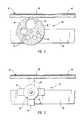
- FIG. 7is a partial cutaway perspective view of a treadmill having another exemplary embodiment of a cushioning mechanism
- FIG. 8is a partial cross-sectional elevation view of the cushioning mechanism of FIG. 7 taken along section line 8 — 8 therein;
- FIG. 9is a partial cutaway top elevation view of another exemplary embodiment of a cushioning mechanism.
- FIG. 10is a partial cross-sectional elevation view of another exemplary embodiment of a cushioning mechanism
- FIG. 11is a partial cross-sectional perspective view of another exemplary embodiment of a cushioning mechanism
- FIG. 12is a partial cut-away top elevation view of another exemplary embodiment of a cushioning mechanism
- FIG. 13is a perspective view of a treadmill having another exemplary embodiment of a cushioning mechanism
- FIG. 14is a bottom view of a cushioning member of the treadmill featured in FIG. 13 shown adjacent a deck illustrated in a cutaway, exploded view;
- FIG. 15is a cutaway top view of the treadmill of FIG. 13 with first and second cushioning members of the cushioning mechanism shown partially in phantom views;
- FIG. 16 ais a top view of a cushioning member frame with cushioning pads shown in a cutaway view mounted therein.
- FIG. 16 bis a bottom view of the cushioning member frame of FIG. 17 a without the pads shown therein;
- FIG. 17is a cutaway top view of an alternate treadmill having the cushioning mechanism of FIG. 14 therein (shown partially in phantom lines) and having an aperture through the deck and side rail to thereby view a selected cushioning setting;
- FIG. 18is a bottom view of an alternate cushioning member with numbers indicating different cushioning portions shown in phantom lines;
- FIG. 19is a partially cutaway side view of an alternate treadmill having an aperture through the treadmill side rail and deck to thereby allow viewing of the number shown in phantom view in FIG. 18 .
- FIG. 20illustrates another exemplary embodiment of a cushioning mechanism comprising a spring and a screw selectively mounted therein.
- the screwis shown in a cross sectional view.
- the present inventionrelates to treadmills with an impact absorbing mechanism that is configured to selectively adjust the cushioning of a user's impact.
- FIG. 1Depicted in FIG. 1 is one embodiment of a treadmill incorporating the features of the present invention.
- the adjustable impact absorbing mechanism in the present inventionallows a user to select the amount of cushioning that will be provided by selectively adjusting the impact absorbing mechanism to individualize the amount of cushioning for a specific user as well as for a particular type of exercise. The adjustments made by a user to the impact absorbing mechanism are done without any disassembly of the treadmill.
- a treadmill 10includes an exercise base and a support structure 14 .
- Support structure 14comprises a handrail 16 that extends upwardly from exercise base 12 and a feet means for supporting treadmill 10 upon a support surface such as a floor.
- feet meansis illustrated as feet 18 , which are located on both the right side of handrail 16 and on the left side of handrail 16 , wherein left and right are defined when a user is facing support structure 14 while standing on exercise base 12 .
- Handrail 16may comprise an optional control console 17 that is attached to the upper end of handrail 16 and extends laterally over exercise base 12 .
- Console 17may have an operating control such as an actuator switch to operate treadmill 10 and an indicator means that may be operated by the user to determine various parameters associated with the exercise being performed.
- Console 17may also include a cup or glass holder so that the user may position a liquid refreshment for use during the course of performing the exercise.
- consolesmay be used. In fact, console 17 may only include on/off switch and therefore may be completely replaced by a lateral support member.
- Exercise base 12includes a front end 20 and a back end 22 . As illustrated in FIG. 1, front end 20 of exercise base 12 is attached to support structure 14 and is rotatably attached to support structure 14 such that exercise base 12 may be rotated between an operational position, (illustrated in FIG. 1) and a storage position in which exercise base 12 is substantially vertical. Those skilled in the art will appreciate that various other methods of attaching exercise base 12 to support structure 14 are equally effective in carrying out the intended function thereof. In addition, there is no requirement that exercise base 12 be rotatable. It is contemplated that exercise base 12 can be fixedly attached to support structure 14 .
- exercise base 12comprises a frame 24 that includes a right frame member 28 and a left frame member (not shown). In FIG. 1, however, only the right side of treadmill 10 is visible. It is intended that the left side of frame 24 be a mirror image of the structure discussed relative to the right side.
- Right frame member 28 and left frame member (not shown)are in a spaced-apart, longitudinal relationship and are substantially parallel.
- Exercise base 12also comprises a rear support member 30 that is attached to right frame member 28 and left frame member (not shown) at back end 22 of exercise base 12 .
- Exercise base 12comprises a front roller 34 and a back roller 36 that are attached laterally near front end 20 and back end 22 of frame 24 , respectively.
- An endless belt 32is trained over front roller 34 and back roller 36 and is positioned between right frame member 28 and left frame member (not shown) so that belt 32 includes an upwardly exposed exercise section 38 upon which a user exercises.
- exercise base 12includes a deck 40 that is disposed between exercise section 38 of belt 32 and frame 24 .
- Deck 40is substantially rigid and provides a rigid support to a user exercising on exercise section 38 of belt 32 .
- Deck 40 and belt 32are configured to receive a user thereon for the performance of exercise, including walking, running, jogging and other similar related activities.
- Treadmill 10may also be used for stationary exercises such as stretching or bending while the user is standing on belt 32 .
- the front end 20 and/or back end 22 of deck 40are not secured to the frame. Instead, end 20 and/or 22 move freely from frame 24 to permit a greater adjustment of cushioning.
- the back end 22 of deck 40is secured to frame 24 (through the use of screws, or similar connectors), but the front end 20 of deck 40 is not secured to frame 24 . As such, the front end 20 deflects freely from frame 24 to permit a greater adjustment of cushioning applied to the front end 20 of deck 40 .
- both front end 20 and back end 22 of deck 40are secured to frame 24 and an adjustable cushioning is applied to the central portion of deck 40 between opposing ends 20 and 22 .
- the adjustable cushioningmay be applied in front and/or in back of the points of securement of deck 40 to frame 24 .
- right frame member 28 and left frame membercomprises a side rail 42 and a side platform 44 .
- side platform 44is positioned over the top of side rail 42 of both right frame member 28 and left frame member (not shown).
- Side platforms 44are positioned on each side of belt 32 and are capable of supporting the weight of a user standing thereon.
- side platforms 44are such that a user of treadmill 10 can comfortably and easily step off of belt 32 onto one or both of side platforms 44 .
- a usercan also stand on side platform 44 on either side of exercise base 12 until he or she is ready to step onto belt 32 .
- frame 24that include right frame member 28 and left frame member (not shown) or the components thereof are equally effective in carrying out the intended function thereof.
- the present inventionincludes an impact absorbing mechanism 48 that is configured for manual adjustment to provide selectable amounts of impact cushioning when a user is operating on exercise section 38 of belt 32 .
- Impact absorbing mechanismwhich is an example of an impact absorbing means, allows the amount of cushioning provided by treadmill 10 to be manually adjusted to individualize treadmill 10 for different uses and/or users.
- impact absorbing mechanism 48comprises a plurality of cushioning members 50 that are positioned between deck 40 and frame 24 .
- FIG. 1illustrates two (2) cushioning members 50 , it can be appreciated that various other numbers of cushioning members 50 may be used.
- Cushioning members 50are attached to opposing sides of frame 24 and are at least partially disposed between frame 24 and deck 40 .
- Cushioning members 50are substantially opposite to each other on frame 24 and are substantially perpendicular to deck 40 .
- Cushioning members 50comprise a plurality of portions having different cushioning properties.
- cushioning members 50are attached to the inside surface of frame 24 . It is contemplated, however, that cushioning members 50 may be attached to the outside surface of frame 24 and perform the function thereof equally effectively.
- Cushioning members 50comprise flexible bases 58 that include apertures 52 of varying sizes. As the size of aperture 52 increases, the stiffness of that portion of base 58 cushioning members 50 decreases. As a result, the size of aperture 52 in base 58 of cushioning members 50 is related to the flexibility provided by that portion of cushioning members 50 .
- the portions of cushioning member 50include different cushioning properties due to the varying size of the apertures to allow a user of treadmill 10 who may desire less cushioning, for example, to manually adjustably position cushioning members 50 so that the portion of cushioning members 50 with the smallest aperture 52 and, therefore, the least flexibility is proximate to deck 40 . In this position, cushioning members 50 have an increased stiffness that results in less cushioning. In contrast, when more cushioning is desired, cushioning members 50 are rotated to adjust cushioning members 50 so that a portion of bases 58 with progressively increasing sized apertures is against deck 40 to increase the flexibility and cushioning of cushioning members 50 .
- bases 48 of cushioning members 50are configured in a disk-like shape. While bases 58 , as shown, are substantially planar, it is not required that bases 58 be planar. Instead, bases 58 may have various other configurations such as elliptical, oval, or octagonal. The shape of bases 58 is not particularly important since various other configurations of bases 58 are equally effective in carrying out the intended function thereof. What is important is that bases 58 of cushioning members 50 have portions of differing amounts of stiffness to correspondingly provide different amounts of cushioning in absorbing the impact between deck 40 and frame 24 when a user is operating on exercise section 38 of belt 32 . Cushioning members 50 provide selectable amounts of impact cushioning.
- impact absorbing mechanism 48also comprises means for selectively adjusting cushioning members 50 so as to selectively position one of the plurality of portions of cushioning members 50 between frame 24 and deck 38 .
- means for selectively adjusting cushioning members 50so as to selectively position one of the plurality of portions of cushioning members 50 between frame 24 and deck 38 .
- manually a usermay be able to physically move or rotate cushioning members 50 or press a button on console 17 to cause cushioning members 50 to be automatically and selectively adjusted to provide the desired amount of cushioning.
- handle 56is mounted outside frame 24 and is attached to one of cushioning members 50 .
- Handle 56is configured to cooperate with frame 24 .
- Other embodiments of handle 56perform the function thereof equally effectively.
- handle 56may be a knob attached to base 58 of one of cushioning members 50 , particularly if cushioning members 50 are attached to the outside surface of frame 24 .
- Handle 56may be elongated, oval, round, square, or may include various other geometric shapes. Handle 56 must just be something that the user can easily grasp.
- Other embodiments of handle 56may include some type of an elongated lever or rod.
- means for selectively adjusting cushioning members 50may comprise a button that is indexed to automatically and incrementally adjust cushioning members 50 to the specific amounts of cushioning.
- Other embodiments of means for selectively adjusting cushioning members 50are some sort of a lever that is slidable on console 17 or a knob attached to console 17 that may be selectively rotated. Either the knob, the lever or some other embodiment may be moved on the console 17 by the user to position bases 58 of cushioning members 50 to corresponding positions to provide the selected amount of cushioning.
- Impact absorbing mechanism 48may optionally comprise means for mechanically interconnecting cushioning members 50 such that movement of one of cushioning members 50 results in corresponding movement of the other second cushioning members 50 .
- One embodiment of structure capable of performing the function of such a means for mechanically interconnecting the plurality of cushioning members 50comprises an elongated axle 54 that is depicted in FIG. 1 .
- Axle 54is attached to cushioning members 50 and extends laterally therebetween. As the user of treadmill 10 adjusts one of cushioning members 50 using handle 56 to select the desired amount of cushioning, axle 54 translates the movement to the remaining cushioning members 50 . Consequently, all of cushioning members 50 move substantially simultaneously to the selected position to provide the desired amount of cushioning.
- axle 54is substantially round.
- Axle 54could, however, have other embodiments such as a square, an oval, a rectangle, or another shape.
- Various other configurations of means for mechanically interconnecting first and second cushioning members 50are capable of performing the function thereof equally effectively.
- means for mechanically interconnecting cushioning members 50may comprise a linkage or a cable as will be discussed in further detail below.
- first and second cushioning members 50may each have a handle, such as handle 56 , attached thereto.
- This embodimentwould require a user to first make the adjustment to first cushioning member 50 located on one side of treadmill 10 and then move to the opposite side to manually adjust to second cushioning member 50 or vice versa.
- the drawback with this embodimentis in that a user might forget to adjust cushioning members 50 on the opposite side or may inadvertently adjust only cushioning members 50 on one side of treadmill 10 resulting in cushioning members 50 having different settings.
- adjustable cushioning membersmay be provided along the length of the base 12 in order to provide a substantially horizontal deck 40 . It is also possible to employ both adjustable and non-adjustable cushioning members between frame 24 and deck 40 in order to provide a substantially horizontal deck 40 .
- FIG. 3depicts another embodiment of impact absorbing mechanism 66 .
- One of a plurality of cushioning members 68is shown in FIG. 3 .
- Impact absorbing mechanism 66comprises a plurality of substantially identical cushioning members 68 that is movably attached to frame 24 and is substantially perpendicular to deck 40 .
- cushioning members 68each may be attached either inside or outside frame 24 .
- Cushioning members 68comprise a plurality of portions having different cushioning properties.
- Cushioning members 68each comprise a base 72 having a plurality of arms 70 projecting therefrom.
- base 72is substantially round.
- Various other configurations of base 72are capable of performing the function thereof with equal effectiveness.
- Base 72could, for example, alternatively be square, oval, elliptical, octagonal, triangular, or another shape.
- Arms 70project radially from base 72 . While FIG. 3 illustrates that cushioning members 68 have four (4) arms 70 , it is contemplated that any number of arms 70 other than one (1) can be utilized. What is important is that the user can manually adjust cushioning members 68 to select between differing amounts of cushioning. Arms 70 and base 72 are substantially parallel.
- Arms 70 of cushioning members 68are made of various materials with each having a different stiffness characteristic such that each of arms 70 experiences a differing amount of deflection when contacting deck 40 in response to a force from the impact of a user on exercise section 38 of belt 32 .
- arms 70are substantially comprised of materials selected from the group consisting of plastic, hard rubber, soft rubber, and cellular foam. Various other kinds of materials that have differing stiffness characteristics may alternatively be used.
- arms 70may have other configurations such as being square, semispherical, half an ellipse, half an oval, or a truncated cone and perform the function thereof equally effectively.
- FIG. 4illustrates another embodiment of an impact absorbing mechanism 80 that comprises cushioning members 82 .
- cushioning members 82are movably attached to frame 24 and are disposed substantially perpendicular to deck 40 .
- Cushioning members 82comprise a plurality of portions having different cushioning properties.
- Cushioning members 82comprise a base 92 with arms 84 extending therefrom.
- cushioning members 82are substantially fan-shaped.
- cushioning members 82have arms 84 extending outwardly from base 92 .
- cushioning members 82have three (3) arms 84 .
- cushioning members 82could, however, have various other numbers of arms 84 .
- cushioning members 68 and 92 illustrated in FIGS. 3 and 4have arms 70 and 84 , respectively, that are parallel to bases 72 and 92 , respectively, arms 70 and 84 are not required to be parallel to bases 72 and 82 . Instead, bases 72 or 92 could be mounted on frame 24 so as to be substantially parallel with deck 40 . Arms 70 or 84 while extending outwardly from bases 72 or 92 now extend upward toward deck 40 . For example, arms 70 and 84 could be “L-shaped.” This embodiment of cushioning members performs the function thereof equally effectively.
- Impact absorbing mechanism 80includes an optional raised portion 86 on deck 40 that extends away from deck 40 toward frame 24 .
- Raised portion 86is configured to cooperate with arms 84 on cushioning members 82 .
- raised portion 86 of deck 40can be eliminated and arms 84 of cushioning members 82 extended to directly contact deck 40 as in the embodiment illustrated in FIG. 3 .
- Impact absorbing mechanism 80 with cushioning members 82are somewhat similar to the embodiment of cushioning members 50 illustrated in FIG. 2 .
- arms 84 or base 92 of cushioning members 82have different sized openings 88 formed therein and form a plurality of portions in cushioning members 82 having differing cushioning properties. Openings 88 are differently sized and as a result arms 84 each have differing amounts of stiffness. As shown, one of arms 84 of cushioning members 82 does not have an opening 88 formed therein which further changes the stiffness of that arm 84 .
- each arm 84have a discrete and differing amount of flexibility and deflection in response to a user exercising on belt 32 as a result of the differing stiffness.
- Cushioning members 82consequently, will provide a differing amount of cushioning depending on which of arms 84 is in contact with deck 40 .
- Impact absorbing mechanism 80also comprises an elongated lever 90 , as shown in phantom in FIG. 4, configured to manually adjust cushion members 82 .
- Lever 90is one embodiment of structure capable of performing the function of selectively adjusting cushioning members 82 so as to selectively select one of the plurality of portions of cushioning members 82 between frame 24 and deck 40 .
- FIG. 5illustrates another embodiment of an impact absorbing mechanism 250 that comprises cushioning members 252 .
- cushioning members 252are movably attached to frame 24 and are disposed substantially perpendicular to deck 40 .
- Cushioning members 252comprise a plurality of portions having different cushioning properties.
- Cushioning members 252comprise a substantially fan-shaped base 254 having different flattened surfaces 255 extending around the rim 253 of base 254 .
- Base 254 of cushioning members 252has different sized openings 256 formed therein, forming a plurality of portions in cushioning members 252 having differing cushioning properties. Openings 256 are differently sized and as a result, different portions of base 254 have differing stiffness. As shown, one of the portions 258 of cushioning members 252 does not have an opening 256 formed therein. This further changes the stiffness of that portion 258 . What is important is that each portion have a discrete and differing amount of flexibility and deflection in response to a user exercising on belt 32 as a result of the differing stiffness. Cushioning members 252 , consequently, will provide a differing amount of cushioning depending on which portion contacts deck 40 .
- Impact absorbing mechanism 250also comprises a hub 260 coupling base 254 to axle 54 .
- Hub 260includes fingers 262 (shown in phantom lines) extending radially from a hub sleeve 264 disposed about axle 54 and coupled to axle 54 through the use of a screw (not shown) disposed through sleeve 264 and axle 54 .
- base 254comprises a flexible polyvinylchloride material which is molded onto a nylon or glass-filled nylon hub 260 .
- the polyvinylchloride materialmay have a durometer of about 65, shore A.
- impact absorbing mechanism 250is positioned toward the front end 20 of base 12 , e.g., within the front one-third of base 12 . This positioning is particularly useful when the front end 20 of deck 40 is not secured to frame 24 , e.g., when the back end 22 of deck is secured to frame 24 (through the use of screws, for example), while the front end 20 moves freely from frame 24 . Allowing front end 20 to freely deflect from frame 24 enhances the ability to adjust the amount of cushioning applied to deck 40 . In one such embodiment, front end 20 of deck 40 also rests on at least one additional cushioned member such as an isolator coupled to each side of frame 24 , such as discussed below with reference to FIG. 11 .
- additional cushioned membersuch as an isolator coupled to each side of frame 24 , such as discussed below with reference to FIG. 11 .
- FIGS. 6 a - 6 cillustrate another embodiment of an impact absorbing mechanism 270 that comprises cushioning members 272 .
- Cushioning members 272are movably attached to frame 24 and are disposed substantially perpendicular to deck 40 .
- Cushioning members 272comprise a plurality of portions having different cushioning properties.
- Each cushioning member 272comprises a substantially fan-shaped base 274 having a plurality of recesses 275 extending around the rim 273 of base 274 .
- Base 274 of cushioning member 272comprises a flexible portion 277 attached through adhesion or molding to a substantially more rigid portion 276 , forming a plurality of portions in cushioning members 272 having differing cushioning properties. As a result, different portions of base 274 have differing stiffness. Cushioning members 272 , consequently, will provide a differing amount of cushioning depending on which portion contacts a wheel pivotally coupled to deck 40 , as discussed below.
- Impact absorbing mechanism 270also comprises a hub 280 coupling base 274 to axle 54 .
- Hub 280comprises a hub sleeve 282 coupled to base 274 .
- hub sleeve 282is integrally coupled to member 276 and to a plate 271 , such that flexible portion 277 is cradled within plate 271 , hub 280 and member 276 .
- Hub sleeve 282is disposed about axle 54 and coupled to axle 54 through the use of a screw (not shown) disposed through sleeve 282 and axle 54 , for example.
- flexible portion 277comprises a flexible polyvinylchloride material which is molded onto a significantly more rigid nylon or glass-filled nylon member 276 and plate 271 .
- Hub 280may also comprise nylon or glass-filled nylon.
- the polyvinylchloride material 277may have a durometer of about 55, shore A.
- Impact absorbing mechanism 270further comprises a wheel 288 rotatably coupled to deck 40 .
- bracket 290couples wheel 288 to deck 40 .
- Wheel 288is configured to mate with a selected recess 275 on cushioning member 272 .
- Wheel 288turns as cushioning member 272 turns. This assists in preserving the material of cushioning member 272 from damage as member 272 is turned. Stops 292 coupled to bracket 290 prevent the overrotation of cushioning member 272 .
- axle 54includes a tab 294 coupled to axle 54 .
- a motorsuch as an extension motor, has an arm 293 thereof pivotally coupled to tab 294 .
- the motorrotates the axle 54 .
- the button and motor pivotally coupled to axle 54serve as another example of a structure capable of performing the function of selectively adjusting cushioning members 272 so as to select one of the plurality of portions of cushioning members 272 between frame 24 and deck 40 .
- impact absorbing mechanism 250is positioned toward the front end 20 of base 12 , e.g., within the front one-third of base 12 .
- One or both of front and back ends 20 , 22 of deck 40are secured to frame 24 .
- rigid portion 276comprises a rim 269 having a T-shaped member 279 extending therefrom. Member 279 is covered by flexible portion 277 and enhances the adhesion of flexible portion 277 to the more rigid portion 276 .
- FIGS. 7 and 8depicts treadmill 10 with another embodiment of an impact absorbing mechanism 100 configured for manual adjustment to provide selectable amounts of impact cushioning when a user is operating on exercise section 38 of belt 32 .
- Impact absorbing mechanism 100comprises cushioning members 102 .
- cushioning members 102are substantially parallel to deck 40 and are at least partially disposed between deck 40 and frame 24 .
- Cushioning members 102can be movably attached to either deck 40 or frame 24 .
- cushioning members 102are rotatably attached to deck 40 by a vertical axle 108 .
- Cushioning members 102 illustrated in FIGS. 7 and 8have substantially the same configuration as cushioning members 50 depicted in FIGS. 1 and 2.
- Cushioning members 102comprise a plurality of portions having different cushioning properties.
- Cushioning members 102comprise a base 112 with a plurality of openings 52 formed therein. Bases 112 of cushioning members 102 are shown as round, but it is intended, particularly in this embodiment, that cushioning members 102 may have various other shapes without effecting the function thereof.
- Cushioning members 102may be square, rectangular, oval, or various other configurations.
- treadmill 10has a knob 110 on console 117 that causes cushioning members 102 to be selectively adjusted according to the desired amount of cushioning.
- Knob 110 on console 117is one embodiment of structure capable of performing the function of a means for selectively adjusting cushioning members 102 to provide differing amount of impact cushioning.
- Various other embodiments of structure capable of performing the function of such a means for selectively adjusting members 102 including those disclosed with other embodiments of cushioning members,are equally effective.
- Impact absorbing mechanism 100also comprises a linkage or a cable 106 , shown in FIG. 7, configured to mechanically interconnect cushioning members 102 such that movement of one cushioning member 102 results in corresponding movement of other cushioning members 102 .
- a linkage or a cable 106shown in FIG. 7, configured to mechanically interconnect cushioning members 102 such that movement of one cushioning member 102 results in corresponding movement of other cushioning members 102 .
- Various embodiments of structure capable of performing the function of such means for mechanically interconnecting cushioning members 102including those disclosed with other embodiments of cushioning members, are equally effective.
- horizontal axle 54can be mechanically interconnected with vertical axles 108 of cushioning members 102 such that movement of one of cushioning members 102 results in corresponding movement of other cushioning members 102 .
- bases 112 of cushioning members 102are depicted as having various sized openings 52 formed therein, other embodiments of cushioning members 102 perform the function thereof equally effectively.
- raised padscomprising materials with different cushioning properties can be mounted on cushioning members 102 .
- Cushioning members 102can be selectively adjusted such that the raised pads mounted on cushioning members 102 are selectively positioned on raised portion 104 .
- cushioning members 102instead of cushioning members 102 being pivotally mounted below deck 40 , cushioning members 102 can be movably attached to frame 24 by vertical axles.
- Impact absorbing mechanism 120comprises cushioning members 122 attached to opposite sides of frame 24 .
- Cushioning members 122are elongated and in the embodiment shown in FIG. 9 are substantially curved.
- cushioning members 122can be rectangular, square, semispherical, half an oval, half-an-ellipse, or semicircular.
- cushioning members 122comprise bases 30 that have a plurality of raised pads 124 mounted thereon. Raised pads 124 each comprise a material with different cushioning properties.
- the arrangement of raised pads 124 on cushioning members 122 on side oneis in an inverse mirror image cushioning members 122 on the opposite side of frame 24 as will be discussed in more detail below.
- Impact absorbing mechanisms 120also comprise an elongated beam 126 movably mounted below deck 40 .
- Beam 126extends across frame 24 and is substantially parallel to deck 40 .
- a portion of beam 126is disposed between deck 40 and cushioning members 122 to contact the various raised pads 124 .
- Beam 126is pivotally connected to deck 40 .
- Raised pads 124are arranged on cushioning members 122 so that beam 126 is pivoted to contact one type of raised pad 124 on cushioning members 122 and the opposite end of beam 126 contacts the same material on the opposite of cushioning members 122 as illustrated in FIG. 9 .
- Beam 126is another embodiment of structure capable of performing the function of such means for mechanically interconnecting the plurality of cushioning members 122 .
- Beam 126has an elongated handle 128 attached to one end thereof for the user to grasp to selectively, manually adjust the amount of cushioning provided by cushioning members 122 .
- a user of treadmill 10can move beam 126 by moving handle 128 until beam 126 contacts the selected raised pads 124 to obtain differing amounts of cushioning of the impact.
- FIG. 9illustrates in phantom an example of another position of beam 126 for a differing amount of cushioning.
- Handle 128extends away from beam 126 above frame 24 .
- Handle 128is one example of structure capable of performing the function of means for selectively positioning one of the plurality of portions of cushioning members 122 .
- Cushioning members 50 , 68 , 82 , 102 and 122are one embodiment of structure capable of performing the function of impact absorbing means for selectively adjusting the cushioning impact between deck 40 and frame 24 .
- FIG. 10illustrates another embodiment of impact absorbing mechanism 140 that comprises a plurality of flexible cantilevers 142 .
- Cantilevers 142comprise a support 144 attached to the inside surface of frame 24 and extends in a direction away from frame 24 .
- Cantilevers 142comprise an elongated flexible arm 146 that is attached at one end to support 144 . Arm 146 extends toward front end 20 of frame 24 . Arm 146 has an opposite end that is freely disposed from support 144 and frame 24 .
- Cantilevers 142also comprise a bumper 148 mounted on the free end of arm 146 . Bumper 148 extends away from free end of arm 146 toward deck 40 in a direction that is substantially perpendicular to deck 140 .
- Impact absorbing mechanism 140includes an elongated brace 150 that is configured to manually adjust the flexibility of cantilevers 142 .
- Brace 150is mounted to frame 24 adjacent to cantilevers 142 .
- Brace 150extends substantially perpendicular to the longitudinal axis of frame 24 and is configured to cooperate with frame 24 and to move parallel to the longitudinal axis of frame 24 .
- frame 24has elongated slots 152 formed therein to accommodate movement of brace 150 , which is selectively movable along the longitudinal axis of frame 24 and the length of cantilever 142 to change in the amount of cushioning provided by cantilevers 142 by increasing or decreasing the amount of deflection of arm 146 in response to a user operating on the exercise section 38 of belt 32 .
- brace 150For example, if brace 150 is moved along the length of cantilevers 142 towards bumper 148 on arm 146 , the amount of deflection or amount of cushioning is decreased. In contrast, if brace 150 is moved towards support 144 , the amount of deflection will increase which consequently results in the amount of cushioning provided to the user increasing.
- brace 150 and slots 152perform the function thereof equally effectively as long as brace 150 and slots 152 are configured to cooperate together.
- Brace 150 and slots 152 in frame 24are one example of structure capable of performing the function of an adjustment means for selectively adjusting the flexibility of cantilever 142 .
- FIG. 11illustrates yet another embodiment of an impact absorbing mechanism 160 that comprises a plurality of flexible cantilevers 162 , only one of which is shown in FIG. 11 .
- Cantilever 162comprises a support 164 attached to the inside surface of frame 24 , such as a cross beam.
- Cantilever 162further comprises an elongated arm 166 , such as a steel or other metal arm that is attached at one end to support 164 .
- Arm 166extends toward front end 20 of frame 24 .
- Arm 166has an opposite end that is freely disposed from support 164 and frame 24 .
- Cantilever 162also comprises a bumper 168 mounted on the free end of arm 166 .
- Bumper 168extends away from the free end of arm 166 toward deck 40 in a direction that is substantially perpendicular to deck 40 .
- another elongated arm and a bumper attached theretoextends from an opposing end of support 164 in parallel relationship to the cantilever 162 shown in FIG. 11 .
- bumper 168is positioned toward the front end 20 of base 12 , e.g., within the front one-third of base 12 .
- Impact absorbing mechanism 160further includes an elongated brace 170 that is configured to manually adjust the flexibility of cantilevers 162 .
- Brace 170is mounted to frame 24 adjacent to cantilevers 162 .
- Brace 170extends substantially perpendicular to the longitudinal axis of frame 24 and is configured to cooperate with frame 24 and to move parallel to the longitudinal axis of frame 24 .
- frame 24has elongated slots 172 formed therein to accommodate movement of brace 170 .
- a second slotis not shown in FIG. 11, but is preferably on an opposing side of frame 24 from slot 172 for receiving an opposing end of brace 170 from that shown in FIG. 11 .
- Brace 170is selectively movable along the longitudinal axis of frame 24 within opposing slots 172 and along the length of opposing cantilevers 162 to change the amount of cushioning provided by cantilevers 162 by increasing or decreasing the amount of deflection of arms 166 in response to a user operating on the exercise section 38 of belt 32 .
- brace 170For example, if brace 170 is moved along the length of cantilever 162 towards bumper 168 on arm 166 , the amount of deflection or amount of cushioning is decreased. In contrast, if brace 170 is moved towards support 164 , the amount of deflection will increase which consequently results in the amount of cushioning provided to the user increasing.
- each of the opposing slots 172have teeth 174 therein for selectively receiving gears 176 coupled to opposing ends of brace 170 .
- Teeth 174 and gears 176allow convenient adjustment of brace 170 within slots 172 and assist in maintaining brace 170 in a desired orientation within slots 172 during an exercise routine.
- each of the opposing cantilevers 162is adjusted, preferably achieving an equal degree of deflection.
- brace 170 and slots 172perform the function thereof equally effectively as long as brace 170 and slots 172 are configured to cooperate together.
- Brace 170 and slots 172 in frame 24are one example of structure capable of performing the function of an adjustment means for selectively adjusting the flexibility of cantilever 162 .
- front end 20 of deck 40is not secured to frame 24 .
- back end 22 of deck 40is secured to frame 24 (through the use of screws, for example), while front end 20 moves freely from frame 24 , enhancing the ability to adjust the amount of cushioning applied to front end 20 of deck 40 .
- front end 20 of deck 40also rest on a cushioned isolator 180 , shown in FIG. 11, without being coupled to the isolator 180 .
- front end 20 and back end 22 of deck 40are both coupled to frame 24 through the use of screws, for example.
- the screwsmay be disposed through the deck, the frame, and an isolator, such as isolator 180 disposed between the frame and the deck, for example.
- FIG. 12Another example of an impact absorbing mechanism 200 that comprises a plurality of flexible cantilevers 202 , 204 is shown in FIG. 12 .
- Cantilevers 202 , 204comprise a support 205 attached to frame 24 diagonally with respect to the longitudinal axis of frame 24 .
- Cantilevers 202 , 204further comprise respective elongated arms 206 , 208 attached to opposing ends of diagonal support 205 .
- Bumpers 207 , 209are coupled to free ends of respective arms 206 , 208 below deck 40 .
- Bumpers 207 , 209extend upwardly with respect to respective arms 206 , 208 and intersect deck 40 .
- bumpers 207 , 209 and arms 206 , 208 of respective cantilevers 202 , 204are oriented in opposing directions.
- Impact absorbing mechanism 200further includes an elongated brace 210 that is configured to manually adjust the flexibility of cantilevers 202 , 204 .
- Brace 210is mounted to frame 24 by being pivotally coupled to support 205 .
- Brace 210has opposing ends which are disposed beneath respective arms 206 , 208 .
- Frame 24has elongated slots 212 , 214 formed therein on opposing sides to accommodate pivotal movement of the ends of brace 210 .
- Brace 210moves along the length of opposing cantilevers 202 , 204 to change in the amount of cushioning provided by cantilevers 202 , 204 by increasing or decreasing the amount of deflection of arms 202 , 204 .
- One advantage of mechanism 200is that the amount of cushioning provided is adjustable by pivoting brace 210 in a desired direction.
- Brace 210 and slots 212 , 214 in frame 24are one example of structure capable of performing the function of an adjustment means for selectively adjusting the flexibility of cantilevers 202 , 204 .
- treadmill 10includes structure such as a drive means for supplying power to exercise base 12 to drive continuous belt 32 .
- the drive means for supplying power to base frame 12is disposed in front end 20 of exercise base 12 .
- One embodiment of structure capable of performing the function of such a drive meanscomprises a motor that rotates a first pulley and drives a belt.
- the beltdrives a second pulley which is connected to front roller 34 about which belt 32 is disposed.
- the rear portion of belt 32is also disposed around rear roller 36 .
- Other embodiments capable of performing the function of such a drive meansmay include a flywheel.
- the flywheelis connected to belt 32 and receives energy from the user operating on belt 32 of exercise base 12 .
- the flywheelalso delivers energy to belt 32 as the user performs walking, running or jogging exercises when a user is suspended and not in contact with belt 32 .
- FIGS. 13-16 bdepict an alternate treadmill 310 with another embodiment of an impact absorbing mechanism 300 configured for selective adjustment to provide selectable amounts of impact cushioning when a user is operating on exercise section 338 of belt 332 .
- Treadmill 310comprises an exercise base 304 comprising: (i) frame 324 , which can be the same or similar to the frame 24 of FIGS. 1 and 7; (ii) endless belt 332 trained about front and rear rollers coupled between opposing ends of right and left frame members 325 , 326 (FIG. 15 ), such as discussed regarding belt 38 of FIGS. 1 and 7; (iii) a deck 340 (FIGS. 14-15) coupled to frame 324 , such as discussed regarding deck 40 of FIGS. 1 and 7; and (iv) impact absorbing mechanism 300 at least partially disposed between deck 340 and frame 324 .
- a support structure 306is coupled to base 304 (e.g., rotatably coupled to the base 304 such that the base 304 can be selectively oriented in an operational position, as shown in FIG. 13, or an upright storage position).
- Impact absorbing mechanism 300which is another example of an impact absorbing means, comprises first and second cushioning members 302 (FIGS. 14-15) on opposing sides of treadmill 310 .
- Cushioning members 302are substantially parallel to deck 340 and are at least partially disposed between deck 340 and frame 324 . While cushioning members 302 can be movably attached to either deck 340 or frame 324 , in the embodiment of FIG. 14 cushioning members 302 are rotatably attached to deck 340 by a vertical axle 308 , such that frame 324 of treadmill is contacted by downwardly extending cushioning members 302 .
- Member 302has a plurality of portions, each of which have different cushioning properties, as will be discussed in detail below. To adjust the degree of cushioning, the user causes at least one and preferably both cushioning members 302 to rotate horizontally such that the desired cushioning portion is positioned between the treadmill deck 340 and frame 324 .
- cushioning members 302each comprise a base 312 with a plurality of arms 302 a-c projecting therefrom. Arms 302 a-c , each have different cushioning properties. Thus, cushioning members 302 each have a plurality of cushioning portions, namely arms 302 a-c , each having different cushioning properties. Members 302 each have a generally triangular shape. However, it is intended that the cushioning members that rotate horizontally to adjust the degree of cushioning may have various other shapes without effecting the function thereof, such as square, rectangular, oval, propeller shaped, or various other configurations.
- a spring loaded ball detent 318engages one of three recessed areas 320 a-c (FIG. 15) on the top surface of cushioning member 302 , depending upon the degree of cushioning selected by the user.
- the recessed areas 320 a-care positioned so as to selectively engage the detent 318 and thereby hold the desired respective arm 302 a-c in place between deck 340 and frame 324 .
- the same resultmay be achieved by placing a detent in cushioning member 302 which could engage one of a number of different recessed areas in deck 340 or frame 324 .
- the detentcan be molded as part of cushioning member 302 .
- Differing degrees of cushioningcan be achieved in cushioning members 302 by (i) providing cushioning portions comprising differing materials; (ii) providing cushioning portions having differing levels of flexibility; (iii) providing cushioning portions having different sizes and/or (iv) providing cushioning portions that are more hollow than others, for example.
- a variety of different methods of manufacturemay be employed to form each member 302 .
- each member 302is formed by forming a frame 314 configured to hold a plurality of cushioning pads 316 a-c therein.
- Each arm portion 302 a-ccomprises (i) a respective frame portion 317 a-c ; and (ii) a respective pad 316 a-c coupled to a respective frame portion 317 a-c.
- frame 314comprises a rigid or semi-rigid material, while cushioning pads 316 a-c each comprise a more flexible material that is coupled onto frame 314 , e.g., through molding.
- frame 314may comprise a material that is more rigid than pads 316 a-c for example.
- frame 314is molded, after which pads 316 a-c are molded thereon.
- the frame and/or pad portions of cushioning members 302can be formed from SANTOPRENE, PVC, thermoplastic elastomer, foam and/or other suitable material.
- the frame 314 and pads 316 a-ceach comprise a SANTOPRENE material, but have different degrees of flexibility.
- Frame 314is configured to receive different pads therein, the pads being shown in a bottom view in FIG. 14, and in a cutaway top view in FIG. 16 a .
- a bottom view of the frameis shown without the pads in FIG. 16 b.
- cushioning frame 314comprises a first frame portion 317 a , a second frame portion 317 b , and a third frame portion 317 c .
- First and second frame portions 317 a-bessentially have large apertures therethrough, such that a significant amount of space is available for corresponding pad material 316 a-b .
- Third frame portion 317 ccomprises more frame material and has less space therein for the corresponding pad material 316 c.
- arm 302 ccomprises a substantial amount of rigid or semi-rigid frame material 317 c and a reduced amount of flexible pad material 316 c
- arm 302 cis more rigid than arms 302 a and 302 b .
- the pad material 316 a of arm 302 ahas a large groove therein, whereas the pad material 316 b of arm 302 b is solid.
- arm 302 ais more flexible than arm 302 b.
- arm 302 ccomprises less pad material 316 c and more frame material 317 c than arm 302 b , and is consequently more rigid than arm 302 b .
- Arm 302 ahas a pad 316 a having a substantial groove therein, and is consequently more flexible than arm 302 b .
- arm 302 cis more rigid than arm 302 b , which is more rigid than arm 302 a .
- a user desiring different cushioning properties for treadmill 310can select a desired level of cushioning.
- arms 302 a-c of cushioning members 302are depicted as having raised pad portions formed thereon that have different internal configurations, other embodiments of cushioning members perform the function thereof, such as by employing pad portions having different sizes or different densities.
- cushioning members 302instead of cushioning members 302 being pivotally mounted below deck 340 , cushioning members 302 can be movably attached to frame 324 by vertical axles.
- Indiciasuch as the numbers 1, 2, and 3 (or other indicia, such as lettering, color coding, providing other symbols, etc.) may be provided on the frame and/or pads of member 302 to allow a user to visually determine which amount of cushioning has been selected.
- the numeral “1”corresponds to the most flexible amount of cushioning (arm 302 a )
- the numeral “2”corresponds to an intermediate amount of flexibility (arm 302 b )
- the numeral “3”corresponds to the most rigid amount of cushioning (arm 302 c ).
- a user desiring an intermediate level of cushioningcan move cushioning members 302 until the number 2 or other indicia appears on the edge of the treadmill of FIG. 15 .
- arms 302 b of members 302are mounted between frame 324 and deck 340 to thereby provide an intermediate level of flexibility to treadmill 310 .
- Gripping grooves 322 on members 302allow a user to conveniently grip a selected member 320 .
- members 302can be selectively adjusted according to the desired amount of cushioning by gripping the gripping grooves 320 and rotating a selected member 302 in a horizontal plane.
- Such grooves 320are one embodiment of structure capable of performing the function of a means for selectively adjusting cushioning members 302 to provide differing amounts of impact cushioning.
- Various other embodiments of structure capable of performing the function of such a means for selectively adjusting members 302may be employed.
- Impact absorbing mechanism 300may further comprise a linkage or a cable (not shown), (e.g., similar to element 106 shown in FIG. 7 ), configured to mechanically interconnect cushioning members 302 such that movement of one cushioning member 302 results in corresponding movement of other cushioning members 302 .
- a linkage or a cable(not shown), (e.g., similar to element 106 shown in FIG. 7 ), configured to mechanically interconnect cushioning members 302 such that movement of one cushioning member 302 results in corresponding movement of other cushioning members 302 .
- a linkage or a cable(not shown), (e.g., similar to element 106 shown in FIG. 7 ), configured to mechanically interconnect cushioning members 302 such that movement of one cushioning member 302 results in corresponding movement of other cushioning members 302 .
- frame 324includes right and left frame members 325 , 326 , such as discussed with reference to base 12 of FIG. 1 .
- Front and back rollersare attached laterally between respective front and back ends of frame members 325 , 326 and an endless belt 332 is trained over the front and back rollers.
- a right side rail 342is shown mounted on deck 340 .
- a left side railmay also be mounted on deck 340 .
- Deck 340may be mounted on frame 324 in a variety of different manners, such as those discussed above with regard to deck 40 and frame 24 .
- the rear portion of the deckis immovably affixed to rear portions of opposing frame members 325 , 326 while the front portion of the deck 340 is coupled to the front portions of opposing frame members 325 , 326 through the use of elastomeric isolators coupled between the deck and the frame that allow some deflection between the deck 340 and the frame 324 during use.
- FIG. 17provides a view of an alternate treadmill embodiment of the present invention, wherein first and second frame members 324 a (only one frame member shown) are positioned below deck 340 a in such as manner that the frame members 324 a are inwardly disposed with respect to the sides of deck 340 a .
- the indiciae.g., the numeral “2”
- a corresponding aperture 341also exists in the side deck rails 342 a , which are mounted on the sides of deck 340 a adjacent the treadmill belt 338 a .
- the deck 340 a and side deck rail 342 a of the present inventioneach have an aperture 341 therethrough such that the user can see through the deck 340 a and rail 342 a to view the indicia (e.g., the numeral “2”) on respective members 302 on opposing sides of the deck 340 a .
- One or both sides of deck 340 a and one or both corresponding deck railsmay have an aperture 341 therethrough corresponding to one or more respective cushioning members 302 .
- FIG. 18provides a top view of an alternate cushioning member 350 of FIG. 17 .
- the cushioning member 350includes a base 351 having a plurality of arms 352 a-c radially extending therefrom.
- Each of the cushioning arms 352 a-chave different cushioning properties to allow a user to selectively adjust the amount of cushioning provided.
- the difference in cushioningmay be achieved through the use of material having different densities, different configurations, different sizes, by hollowing on or more portions, or through the use of stiffer materials surrounded by different amounts of padded material, for example.
- arm 352 bis denser, and consequently more stiff, than arm 352 a and less dense and stiff than arm 352 c .
- the pad on an intermediate level cushioning armis larger than the least cushioned arm and smaller than the most cushioned arm.
- an arm having a hollow or grooved pad, an arm having a solid pad, and an arm comprising more frame material than the other arms, as discussed with reference to member 302are employed.
- Indicia, e.g., numerals corresponding to the differences in flexibilityare shown in phantom lines. These indicia appear on the top portions of arms 352 a-c.
- an example of another cushioning mechanism of the present inventioncomprises first and second cushioning members, configured such as member 350 , on opposing sides of a treadmill between the deck and the frame thereof.
- member 350may be employed on a single side to form a cushioning mechanism.
- the cushioning member 350is coupled between frame 324 a and deck 340 a , such as through the use of a vertical axle.
- Deck rail 342is also shown.
- the deck rail 342 and deck 340 aeach have an aperture 341 therethrough that allows the user to visually inspect the corresponding indicia, e.g., numeral, to thereby determine the amount of cushioning selected by the user.
- the deck rail 342 of FIG. 19has an integral tubular sleeve 358 that fits downwardly within the aperture in deck 340 a to thereby enhance the aesthetic appearance of the aperture in deck 340 a . By viewing through the sleeve 358 , the user can see what level of cushioning has been selected.
- a glass or plastic windowmay be placed in the aperture in the deck and/or rail.
- the deck rail(s) 342 a discussed with respect to FIG. 17may optionally employ the sleeve 358 shown in FIG. 19 .
- the cushioning portions with the indicia thereonmay extend out from the area directly between deck and the frame such that the indicia is visible to the user, or an aperture through the deck may be employed.
- an aperture through the deckmay be employed.
- FIG. 20depicts an alternate embodiment of an adjustable cushioning mechanism 400 for use in an exercise device, such as a treadmill.
- Cushioning mechanism 400comprises a spring 402 and a screw 404 threadedly mounted within the spring 402 .
- Spring 402is coupled between treadmill deck 406 and treadmill frame 408 .
- An aperture 412extends through frame 408 (or optionally, in another embodiment, through the deck) and receives screw 404 therethrough.
- the interior of spring 402is configured to correspond to the threads 410 of screw 404 and to allow screw 404 to be threaded therethrough in a helical fashion.
- the treadmill frame 408is raised off the support surface sufficiently enough that the user can place his/her hand under frame 408 , grip a knob 414 of screw 404 , and selectively thread screw 404 into spring 402 or out of spring 402 to thereby adjust the amount of flexibility achieved.
- the space between the support surface and knob 414allows the user to rotate knob 414 .
- screw 404is coupled to an adjustment mechanism that includes a motor to selectively adjust the cushioning by threading the screw.
- Spring 402may be coupled between deck 406 and frame 408 in a variety of different manners.
- the ends of the deck and the frameare coupled together in such a manner as to maintain spring 402 therebetween.
- one or both ends of the springare embedded into a corresponding deck or frame portion.
- one end (e.g., the top end) of the springmay be embedded in the deck or frame while the opposing portion of the spring is not embedded but rests against the opposing frame or deck portion.
- a screwextends from the deck or frame (or both) and connects with the corresponding end (e.g., the top end) of the spring.
- the opposing ends of the springare captured within cups (i.e., surrounded by the rims of the cups) mounted on respective portions of the deck and frame.
- One or both cupsmay have an aperture therethrough in order to allow the screw to extend therethrough.
- frame 408is internally threaded so as to threadedly receive screw 404 therein.
- screw 404is threadedly received within frame 408 and spring 402 .
- screw 404may comprise an elastomeric, plastic, or similar material, although a variety of different materials may be employed.
- the present inventionrelates to treadmills with an impact absorbing mechanism that is configured to selectively adjust the cushioning of a user's impact.
Landscapes
- Health & Medical Sciences (AREA)
- Cardiology (AREA)
- Vascular Medicine (AREA)
- General Health & Medical Sciences (AREA)
- Physical Education & Sports Medicine (AREA)
- Rehabilitation Tools (AREA)
Abstract
Description
Claims (20)
Priority Applications (2)
| Application Number | Priority Date | Filing Date | Title |
|---|---|---|---|
| US09/953,589US6821230B2 (en) | 1998-09-25 | 2001-09-12 | Treadmill with adjustable cushioning members |
| US10/377,295US7563203B2 (en) | 1998-09-25 | 2003-02-28 | Treadmill with adjustable cushioning members |
Applications Claiming Priority (4)
| Application Number | Priority Date | Filing Date | Title |
|---|---|---|---|
| US09/160,947US6174267B1 (en) | 1998-09-25 | 1998-09-25 | Treadmill with adjustable cushioning members |
| US09/437,387US6280362B1 (en) | 1998-09-25 | 1999-11-10 | Treadmill with adjustable cushioning members |
| US09/777,141US6652424B2 (en) | 1998-09-25 | 2001-02-05 | Treadmill with adjustable cushioning members |
| US09/953,589US6821230B2 (en) | 1998-09-25 | 2001-09-12 | Treadmill with adjustable cushioning members |
Related Parent Applications (1)
| Application Number | Title | Priority Date | Filing Date |
|---|---|---|---|
| US09/777,141Continuation-In-PartUS6652424B2 (en) | 1998-09-25 | 2001-02-05 | Treadmill with adjustable cushioning members |
Related Child Applications (1)
| Application Number | Title | Priority Date | Filing Date |
|---|---|---|---|
| US10/377,295Continuation-In-PartUS7563203B2 (en) | 1998-09-25 | 2003-02-28 | Treadmill with adjustable cushioning members |
Publications (2)
| Publication Number | Publication Date |
|---|---|
| US20020045518A1 US20020045518A1 (en) | 2002-04-18 |
| US6821230B2true US6821230B2 (en) | 2004-11-23 |
Family
ID=27388539
Family Applications (1)
| Application Number | Title | Priority Date | Filing Date |
|---|---|---|---|
| US09/953,589Expired - LifetimeUS6821230B2 (en) | 1998-09-25 | 2001-09-12 | Treadmill with adjustable cushioning members |
Country Status (1)
| Country | Link |
|---|---|
| US (1) | US6821230B2 (en) |
Cited By (79)
| Publication number | Priority date | Publication date | Assignee | Title |
|---|---|---|---|---|
| US6953418B1 (en)* | 2004-03-31 | 2005-10-11 | Wen-Ho Chen | Shock absorption device of a running apparatus |
| US7097593B2 (en) | 2003-08-11 | 2006-08-29 | Nautilus, Inc. | Combination of treadmill and stair climbing machine |
| US7163493B1 (en)* | 2006-01-19 | 2007-01-16 | Hai Pin Kuo | Treadmill having changeable suspension |
| EP1743678A1 (en)* | 2005-07-15 | 2007-01-17 | Brunswick Corporation | Treadmill deck mechanism |
| US20070015636A1 (en)* | 2005-07-15 | 2007-01-18 | Molter Daniel E | Treadmill deck support |
| US20070225127A1 (en)* | 2006-03-22 | 2007-09-27 | Forhouse Corporation | Cushion device for exercise machine |
| US7367926B2 (en) | 2005-08-01 | 2008-05-06 | Fitness Quest Inc. | Exercise treadmill |
| US20080171640A1 (en)* | 2007-01-16 | 2008-07-17 | Dick Chang | Cushion adjustable and display devices for treadmills |
| US7455628B1 (en)* | 2006-01-21 | 2008-11-25 | Stearns Kenneth W | Elliptical exercise methods and apparatus |
| US7455626B2 (en) | 2001-12-31 | 2008-11-25 | Nautilus, Inc. | Treadmill |
| US20080300115A1 (en)* | 2007-05-29 | 2008-12-04 | Sportcraft, Ltd. | Rear mounted pivoting treadmill cushioning |
| US20080312047A1 (en)* | 2007-06-18 | 2008-12-18 | Johnson Health Tech Co., Ltd | Treadmill |
| US20090088301A1 (en)* | 2007-09-28 | 2009-04-02 | Johnson Health Tech Co., Ltd. | Treadmill with cushion assembly |
| US7563203B2 (en) | 1998-09-25 | 2009-07-21 | Icon Ip, Inc. | Treadmill with adjustable cushioning members |
| US20120302408A1 (en)* | 2010-07-29 | 2012-11-29 | George Burger | Single belt omni directional treadmill |
| US20130053222A1 (en)* | 2011-08-29 | 2013-02-28 | Chiu Hsiang Lo | Apparatus for Cushioning a Platform of a Treadmill |
| US20130130869A1 (en)* | 2011-11-22 | 2013-05-23 | Kuang-Hua HOU | Platform for supporting conveyor belt of treadmill |
| US20130196827A1 (en)* | 2012-02-01 | 2013-08-01 | Huang-Tung Chang | Buffer structure of treadmill |
| US20130231219A1 (en)* | 2012-03-05 | 2013-09-05 | Hsuan-Fu HUANG | Treadmill |
| US20130274071A1 (en)* | 2012-04-16 | 2013-10-17 | Leao Wang | Rotary type adjustable cushioning mechanism of a treadmill |
| US8734301B2 (en) | 2011-01-06 | 2014-05-27 | Jebb G. Remelius | Particulate material treadmill |
| US10188890B2 (en) | 2013-12-26 | 2019-01-29 | Icon Health & Fitness, Inc. | Magnetic resistance mechanism in a cable machine |
| US10252109B2 (en) | 2016-05-13 | 2019-04-09 | Icon Health & Fitness, Inc. | Weight platform treadmill |
| US10258828B2 (en) | 2015-01-16 | 2019-04-16 | Icon Health & Fitness, Inc. | Controls for an exercise device |
| US10272317B2 (en) | 2016-03-18 | 2019-04-30 | Icon Health & Fitness, Inc. | Lighted pace feature in a treadmill |
| US10279212B2 (en) | 2013-03-14 | 2019-05-07 | Icon Health & Fitness, Inc. | Strength training apparatus with flywheel and related methods |
| US10293211B2 (en) | 2016-03-18 | 2019-05-21 | Icon Health & Fitness, Inc. | Coordinated weight selection |
| US10343017B2 (en) | 2016-11-01 | 2019-07-09 | Icon Health & Fitness, Inc. | Distance sensor for console positioning |
| US10376736B2 (en) | 2016-10-12 | 2019-08-13 | Icon Health & Fitness, Inc. | Cooling an exercise device during a dive motor runway condition |
| US10426989B2 (en) | 2014-06-09 | 2019-10-01 | Icon Health & Fitness, Inc. | Cable system incorporated into a treadmill |
| US10433612B2 (en) | 2014-03-10 | 2019-10-08 | Icon Health & Fitness, Inc. | Pressure sensor to quantify work |
| US10441844B2 (en) | 2016-07-01 | 2019-10-15 | Icon Health & Fitness, Inc. | Cooling systems and methods for exercise equipment |
| US10441840B2 (en) | 2016-03-18 | 2019-10-15 | Icon Health & Fitness, Inc. | Collapsible strength exercise machine |
| US10449416B2 (en) | 2015-08-26 | 2019-10-22 | Icon Health & Fitness, Inc. | Strength exercise mechanisms |
| US10471299B2 (en) | 2016-07-01 | 2019-11-12 | Icon Health & Fitness, Inc. | Systems and methods for cooling internal exercise equipment components |
| US10493349B2 (en) | 2016-03-18 | 2019-12-03 | Icon Health & Fitness, Inc. | Display on exercise device |
| US10500473B2 (en) | 2016-10-10 | 2019-12-10 | Icon Health & Fitness, Inc. | Console positioning |
| US10543395B2 (en) | 2016-12-05 | 2020-01-28 | Icon Health & Fitness, Inc. | Offsetting treadmill deck weight during operation |
| US10561893B2 (en) | 2016-10-12 | 2020-02-18 | Icon Health & Fitness, Inc. | Linear bearing for console positioning |
| US10561894B2 (en) | 2016-03-18 | 2020-02-18 | Icon Health & Fitness, Inc. | Treadmill with removable supports |
| US10625137B2 (en) | 2016-03-18 | 2020-04-21 | Icon Health & Fitness, Inc. | Coordinated displays in an exercise device |
| US10661114B2 (en) | 2016-11-01 | 2020-05-26 | Icon Health & Fitness, Inc. | Body weight lift mechanism on treadmill |
| US10729965B2 (en) | 2017-12-22 | 2020-08-04 | Icon Health & Fitness, Inc. | Audible belt guide in a treadmill |
| US10786706B2 (en) | 2018-07-13 | 2020-09-29 | Icon Health & Fitness, Inc. | Cycling shoe power sensors |
| US10857421B2 (en) | 2017-05-31 | 2020-12-08 | Nike, Inc. | Treadmill with dynamic belt tensioning mechanism |
| US10918904B2 (en) | 2017-05-31 | 2021-02-16 | Nike, Inc. | Treadmill with vertically displaceable platform |
| US10918905B2 (en) | 2016-10-12 | 2021-02-16 | Icon Health & Fitness, Inc. | Systems and methods for reducing runaway resistance on an exercise device |
| US10940360B2 (en) | 2015-08-26 | 2021-03-09 | Icon Health & Fitness, Inc. | Strength exercise mechanisms |
| US10953305B2 (en) | 2015-08-26 | 2021-03-23 | Icon Health & Fitness, Inc. | Strength exercise mechanisms |
| US11000730B2 (en) | 2018-03-16 | 2021-05-11 | Icon Health & Fitness, Inc. | Elliptical exercise machine |
| US11033777B1 (en) | 2019-02-12 | 2021-06-15 | Icon Health & Fitness, Inc. | Stationary exercise machine |
| US11058913B2 (en) | 2017-12-22 | 2021-07-13 | Icon Health & Fitness, Inc. | Inclinable exercise machine |
| US11058914B2 (en) | 2016-07-01 | 2021-07-13 | Icon Health & Fitness, Inc. | Cooling methods for exercise equipment |
| US11187285B2 (en) | 2017-12-09 | 2021-11-30 | Icon Health & Fitness, Inc. | Systems and methods for selectively rotationally fixing a pedaled drivetrain |
| US11244751B2 (en) | 2012-10-19 | 2022-02-08 | Finish Time Holdings, Llc | Method and device for providing a person with training data of an athlete as the athlete is performing a swimming workout |
| US11298577B2 (en) | 2019-02-11 | 2022-04-12 | Ifit Inc. | Cable and power rack exercise machine |
| US11326673B2 (en) | 2018-06-11 | 2022-05-10 | Ifit Inc. | Increased durability linear actuator |
| US11451108B2 (en) | 2017-08-16 | 2022-09-20 | Ifit Inc. | Systems and methods for axial impact resistance in electric motors |
| US11458356B2 (en) | 2020-02-14 | 2022-10-04 | Life Fitness, Llc | Systems and methods for adjusting a stiffness of fitness machines |
| US11534651B2 (en) | 2019-08-15 | 2022-12-27 | Ifit Inc. | Adjustable dumbbell system |
| US11534654B2 (en) | 2019-01-25 | 2022-12-27 | Ifit Inc. | Systems and methods for an interactive pedaled exercise device |
| US11673036B2 (en) | 2019-11-12 | 2023-06-13 | Ifit Inc. | Exercise storage system |
| US11794070B2 (en) | 2019-05-23 | 2023-10-24 | Ifit Inc. | Systems and methods for cooling an exercise device |
| US11805826B2 (en)* | 2012-02-16 | 2023-11-07 | WB Development Company, LLC | Personal impact protection device |
| US11850497B2 (en) | 2019-10-11 | 2023-12-26 | Ifit Inc. | Modular exercise device |
| US11878199B2 (en) | 2021-02-16 | 2024-01-23 | Ifit Inc. | Safety mechanism for an adjustable dumbbell |
| US11931621B2 (en) | 2020-03-18 | 2024-03-19 | Ifit Inc. | Systems and methods for treadmill drift avoidance |
| US11951377B2 (en) | 2020-03-24 | 2024-04-09 | Ifit Inc. | Leaderboard with irregularity flags in an exercise machine system |
| US12029961B2 (en) | 2020-03-24 | 2024-07-09 | Ifit Inc. | Flagging irregularities in user performance in an exercise machine system |
| US12029935B2 (en) | 2021-08-19 | 2024-07-09 | Ifit Inc. | Adjustment mechanism for an adjustable kettlebell |
| US12176009B2 (en) | 2021-12-30 | 2024-12-24 | Ifit Inc. | Systems and methods for synchronizing workout equipment with video files |
| US12219201B2 (en) | 2021-08-05 | 2025-02-04 | Ifit Inc. | Synchronizing video workout programs across multiple devices |
| US12263371B2 (en) | 2021-04-27 | 2025-04-01 | Ifit Inc. | Devices, systems, and methods for rotating a tread belt in two directions |
| US12280294B2 (en) | 2021-10-15 | 2025-04-22 | Ifit Inc. | Magnetic clutch for a pedaled drivetrain |
| US12337208B2 (en) | 2020-02-14 | 2025-06-24 | Life Fitness, Llc | Noise abatement for fitness machines |
| US12350573B2 (en) | 2021-04-27 | 2025-07-08 | Ifit Inc. | Systems and methods for cross-training on exercise devices |
| US12350547B2 (en) | 2022-02-28 | 2025-07-08 | Ifit Inc. | Devices, systems, and methods for moving a movable step through a transition zone |
| US12409375B2 (en) | 2022-03-18 | 2025-09-09 | Ifit Inc. | Systems and methods for haptic simulation in incline exercise devices |
| US12433815B2 (en) | 2020-10-02 | 2025-10-07 | Ifit Inc. | Massage roller with pressure sensors |
Families Citing this family (17)
| Publication number | Priority date | Publication date | Assignee | Title |
|---|---|---|---|---|
| US9673904B2 (en) | 2009-02-03 | 2017-06-06 | Corning Optical Communications LLC | Optical fiber-based distributed antenna systems, components, and related methods for calibration thereof |
| AU2010210766A1 (en) | 2009-02-03 | 2011-09-15 | Corning Cable Systems Llc | Optical fiber-based distributed antenna systems, components, and related methods for monitoring and configuring thereof |
| US8280259B2 (en) | 2009-11-13 | 2012-10-02 | Corning Cable Systems Llc | Radio-over-fiber (RoF) system for protocol-independent wired and/or wireless communication |
| US8275265B2 (en) | 2010-02-15 | 2012-09-25 | Corning Cable Systems Llc | Dynamic cell bonding (DCB) for radio-over-fiber (RoF)-based networks and communication systems and related methods |
| US9252874B2 (en) | 2010-10-13 | 2016-02-02 | Ccs Technology, Inc | Power management for remote antenna units in distributed antenna systems |
| EP2702780A4 (en) | 2011-04-29 | 2014-11-12 | Corning Cable Sys Llc | Systems, methods, and devices for increasing radio frequency (rf) power in distributed antenna systems |
| CN103548290B (en) | 2011-04-29 | 2016-08-31 | 康宁光缆系统有限责任公司 | Judge the communication propagation delays in distributing antenna system and associated component, System and method for |
| US9352186B2 (en)* | 2012-04-05 | 2016-05-31 | Icon Health & Fitness, Inc. | Treadmill with selectively engageable deck stiffening mechanism |
| WO2013162988A1 (en) | 2012-04-25 | 2013-10-31 | Corning Cable Systems Llc | Distributed antenna system architectures |
| US9455784B2 (en) | 2012-10-31 | 2016-09-27 | Corning Optical Communications Wireless Ltd | Deployable wireless infrastructures and methods of deploying wireless infrastructures |
| US9357551B2 (en) | 2014-05-30 | 2016-05-31 | Corning Optical Communications Wireless Ltd | Systems and methods for simultaneous sampling of serial digital data streams from multiple analog-to-digital converters (ADCS), including in distributed antenna systems |
| US9681313B2 (en) | 2015-04-15 | 2017-06-13 | Corning Optical Communications Wireless Ltd | Optimizing remote antenna unit performance using an alternative data channel |
| US9948349B2 (en) | 2015-07-17 | 2018-04-17 | Corning Optical Communications Wireless Ltd | IOT automation and data collection system |
| WO2018232415A1 (en)* | 2017-06-16 | 2018-12-20 | Core Health & Fitness, Llc | Apparatus, system, and method for flexible treadmill deck |
| KR101991414B1 (en)* | 2018-04-19 | 2019-06-21 | 한국과학기술연구원 | Supporting structure applying gravity compensation mechanism and impact control system having the supporting structure |
| GB2579624B (en)* | 2018-12-07 | 2021-06-23 | Remedy Innovations Ltd | A treadmill exercise apparatus |
| CN112642102B (en)* | 2020-12-30 | 2023-11-28 | 北京金史密斯科技股份有限公司 | Running board adjusting mechanism, running board automatic adjusting method and running machine |
Citations (49)
| Publication number | Priority date | Publication date | Assignee | Title |
|---|---|---|---|---|
| US3592466A (en) | 1969-01-21 | 1971-07-13 | Billie D Parsons | Revolving step exerciser with adjustable slope |
| US3689066A (en) | 1970-09-04 | 1972-09-05 | Oscar M Hagen | Treadmill exercising device with yieldable belt support |
| US4350336A (en) | 1980-10-14 | 1982-09-21 | Hanford Norris E | Exercise treadmill shock-absorbing improvement |
| US4509510A (en) | 1981-12-28 | 1985-04-09 | Hook Clarence L | Massage tread for human skin |
| US4548405A (en) | 1983-02-07 | 1985-10-22 | R. Clayton Lee | Treadmill with trampoline-like surface |
| US4576376A (en) | 1984-11-23 | 1986-03-18 | Miller Paul H | Exercising apparatus |
| US4616822A (en) | 1984-08-01 | 1986-10-14 | Trulaske James A | Exercise treadmill |
| US4819583A (en) | 1986-10-10 | 1989-04-11 | Lake Erie Welding & Fabricating, Inc. | Exercising apparatus |
| US4886266A (en) | 1988-05-23 | 1989-12-12 | True Fitness Technology, Inc. | Exercise treadmill |
| US4938473A (en) | 1988-03-24 | 1990-07-03 | Clayton Lee R | Treadmill with trampoline-like surface |
| US4984810A (en) | 1987-11-25 | 1991-01-15 | Stearns & Mcgee | Treadmill |
| US5072928A (en) | 1987-11-25 | 1991-12-17 | Stearns Mcgee Incorporated | Treadmill |
| US5088729A (en) | 1990-02-14 | 1992-02-18 | Weslo, Inc. | Treadmill frame and roller bracket assembly |
| US5184988A (en) | 1990-01-10 | 1993-02-09 | Precor Incorporated | Exercise treadmill |
| US5250012A (en) | 1991-02-19 | 1993-10-05 | Morris Glenn Whitcomb, Jr. | Running surface for treadmill with trampoline-like surface |
| US5279528A (en) | 1990-02-14 | 1994-01-18 | Proform Fitness Products, Inc. | Cushioned deck for treadmill |
| US5330401A (en) | 1993-03-02 | 1994-07-19 | Orbiter Royalty Trust | Suspension system for treadmill with resilient surface |
| US5336144A (en) | 1992-11-05 | 1994-08-09 | Precor Incorporated | Treadmill with elastomeric-spring mounted deck |
| US5344372A (en) | 1993-11-15 | 1994-09-06 | Michael Hung | Treadmill with collapsible handrails |
| US5374227A (en) | 1993-01-19 | 1994-12-20 | Nautilus Acquisition Corporation | Stair stepping exercise apparatus |
| US5382207A (en) | 1989-06-19 | 1995-01-17 | Life Fitness | Exercise treadmill |
| US5441468A (en) | 1994-03-04 | 1995-08-15 | Quinton Instrument Company | Resiliently mounted treadmill deck |
| US5476430A (en) | 1994-10-28 | 1995-12-19 | Lumex, Inc. | Exercise treadmill with variable response to foot impact induced speed variation |
| US5484362A (en) | 1989-06-19 | 1996-01-16 | Life Fitness | Exercise treadmill |
| US5518471A (en) | 1994-11-07 | 1996-05-21 | Tunturi, Inc. | Exercise treadmill with rearwardly placed incline mechanism |
| US5527245A (en) | 1994-02-03 | 1996-06-18 | Icon Health & Fitness, Inc. | Aerobic and anaerobic exercise machine |
| US5542892A (en) | 1994-08-15 | 1996-08-06 | Unisen, Inc. | Supporting chassis for a treadmill |
| US5626539A (en) | 1996-01-19 | 1997-05-06 | Piaget; Gary D. | Treadmill apparatus with dual spring-loaded treads |
| US5634870A (en) | 1992-09-16 | 1997-06-03 | Wilkinson; William T. | Resilient platform exercise device |
| US5649882A (en) | 1995-10-18 | 1997-07-22 | Universal Gym Equipment, Inc. | Exercise treadmill |
| US5690587A (en) | 1993-04-21 | 1997-11-25 | Gruenangerl; Johann | Treadmill with cushioned surface, automatic speed control and interface to external devices |
| US5749807A (en) | 1993-01-19 | 1998-05-12 | Nautilus Acquisition Corporation | Exercise apparatus and associated method including rheological fluid brake |
| US5827155A (en) | 1991-02-21 | 1998-10-27 | Icon Health & Fitness, Inc. | Resiliently mounted treadmill |
| US5976061A (en) | 1998-04-17 | 1999-11-02 | True Fitness Technology, Inc. | Treadmill having variable running surface suspension |
| US5980432A (en) | 1998-04-16 | 1999-11-09 | Ahman; Daniel | Hopping vehicle |
| US5993358A (en) | 1997-03-05 | 1999-11-30 | Lord Corporation | Controllable platform suspension system for treadmill decks and the like and devices therefor |
| US6013011A (en) | 1997-03-31 | 2000-01-11 | Precor Incorporated | Suspension system for exercise apparatus |
| US6045490A (en) | 1997-12-10 | 2000-04-04 | Shafer; Terry C. | Motorized exercise treadmill |
| US6050921A (en) | 1998-08-24 | 2000-04-18 | Wang; Leao | Top weighted shock absorption structure |
| US6053848A (en) | 1998-08-24 | 2000-04-25 | Eschenbach; Paul William | Treadmill deck suspension |
| US6068578A (en) | 1998-06-12 | 2000-05-30 | Wang; Leao | Buffer structure installed in-between the framework of jogging machine and the floor surface |
| US6132340A (en) | 1999-06-22 | 2000-10-17 | Wang; Leao | Cushioning device for treadmill |
| US6174267B1 (en) | 1998-09-25 | 2001-01-16 | William T. Dalebout | Treadmill with adjustable cushioning members |
| US6174268B1 (en) | 1999-01-29 | 2001-01-16 | Pat J. Novak | Energy absorbing system for exercise equipment |
| US6179753B1 (en) | 1998-10-14 | 2001-01-30 | Illinois Tool Works Inc. | Suspension system for exercise apparatus |
| US6234936B1 (en) | 1998-08-11 | 2001-05-22 | Leao Wang | Top-pressing cushioning mechanism for treadmill |
| US6328676B1 (en) | 1997-06-18 | 2001-12-11 | Technogym S.R.L. | Treadmill |
| US6394239B1 (en) | 1997-10-29 | 2002-05-28 | Lord Corporation | Controllable medium device and apparatus utilizing same |
| US6436008B1 (en) | 1989-06-19 | 2002-08-20 | Brunswick Corporation | Exercise treadmill |
- 2001
- 2001-09-12USUS09/953,589patent/US6821230B2/ennot_activeExpired - Lifetime
Patent Citations (56)
| Publication number | Priority date | Publication date | Assignee | Title |
|---|---|---|---|---|
| US3592466A (en) | 1969-01-21 | 1971-07-13 | Billie D Parsons | Revolving step exerciser with adjustable slope |
| US3689066A (en) | 1970-09-04 | 1972-09-05 | Oscar M Hagen | Treadmill exercising device with yieldable belt support |
| US4350336A (en) | 1980-10-14 | 1982-09-21 | Hanford Norris E | Exercise treadmill shock-absorbing improvement |
| US4509510A (en) | 1981-12-28 | 1985-04-09 | Hook Clarence L | Massage tread for human skin |
| US4548405A (en) | 1983-02-07 | 1985-10-22 | R. Clayton Lee | Treadmill with trampoline-like surface |
| US4616822A (en) | 1984-08-01 | 1986-10-14 | Trulaske James A | Exercise treadmill |
| US4576376A (en) | 1984-11-23 | 1986-03-18 | Miller Paul H | Exercising apparatus |
| US4819583A (en) | 1986-10-10 | 1989-04-11 | Lake Erie Welding & Fabricating, Inc. | Exercising apparatus |
| US4984810A (en) | 1987-11-25 | 1991-01-15 | Stearns & Mcgee | Treadmill |
| US5072928A (en) | 1987-11-25 | 1991-12-17 | Stearns Mcgee Incorporated | Treadmill |
| US4938473A (en) | 1988-03-24 | 1990-07-03 | Clayton Lee R | Treadmill with trampoline-like surface |
| US4886266A (en) | 1988-05-23 | 1989-12-12 | True Fitness Technology, Inc. | Exercise treadmill |
| US5484362A (en) | 1989-06-19 | 1996-01-16 | Life Fitness | Exercise treadmill |
| US5599259A (en) | 1989-06-19 | 1997-02-04 | Life Fitness | Exercise treadmill |
| US5752897A (en) | 1989-06-19 | 1998-05-19 | Brunswick Corporation | Exercise treadmill |
| US6095951A (en) | 1989-06-19 | 2000-08-01 | Brunswick Corporation | Exercise treadmill |
| US5382207B1 (en) | 1989-06-19 | 1998-08-04 | Life Fitness Inc | Exercise treadmill |
| US6436008B1 (en) | 1989-06-19 | 2002-08-20 | Brunswick Corporation | Exercise treadmill |
| US5382207A (en) | 1989-06-19 | 1995-01-17 | Life Fitness | Exercise treadmill |
| US5184988A (en) | 1990-01-10 | 1993-02-09 | Precor Incorporated | Exercise treadmill |
| US5279528A (en) | 1990-02-14 | 1994-01-18 | Proform Fitness Products, Inc. | Cushioned deck for treadmill |
| US5088729A (en) | 1990-02-14 | 1992-02-18 | Weslo, Inc. | Treadmill frame and roller bracket assembly |
| US5250012A (en) | 1991-02-19 | 1993-10-05 | Morris Glenn Whitcomb, Jr. | Running surface for treadmill with trampoline-like surface |
| US5827155A (en) | 1991-02-21 | 1998-10-27 | Icon Health & Fitness, Inc. | Resiliently mounted treadmill |
| US5634870A (en) | 1992-09-16 | 1997-06-03 | Wilkinson; William T. | Resilient platform exercise device |
| US5336144A (en) | 1992-11-05 | 1994-08-09 | Precor Incorporated | Treadmill with elastomeric-spring mounted deck |
| US5454772A (en) | 1992-11-05 | 1995-10-03 | Precor Incorporated | Treadmill with elastomeric-spring mounted deck |
| US5374227A (en) | 1993-01-19 | 1994-12-20 | Nautilus Acquisition Corporation | Stair stepping exercise apparatus |
| US5810696A (en) | 1993-01-19 | 1998-09-22 | Nautilus Acquisition Corporation | Exercise apparatus and associated method including rheological fluid brake |
| US5749807A (en) | 1993-01-19 | 1998-05-12 | Nautilus Acquisition Corporation | Exercise apparatus and associated method including rheological fluid brake |
| US5330401A (en) | 1993-03-02 | 1994-07-19 | Orbiter Royalty Trust | Suspension system for treadmill with resilient surface |
| US5690587A (en) | 1993-04-21 | 1997-11-25 | Gruenangerl; Johann | Treadmill with cushioned surface, automatic speed control and interface to external devices |
| US5344372A (en) | 1993-11-15 | 1994-09-06 | Michael Hung | Treadmill with collapsible handrails |
| US5527245A (en) | 1994-02-03 | 1996-06-18 | Icon Health & Fitness, Inc. | Aerobic and anaerobic exercise machine |
| US5441468A (en) | 1994-03-04 | 1995-08-15 | Quinton Instrument Company | Resiliently mounted treadmill deck |
| US5542892A (en) | 1994-08-15 | 1996-08-06 | Unisen, Inc. | Supporting chassis for a treadmill |
| US5476430A (en) | 1994-10-28 | 1995-12-19 | Lumex, Inc. | Exercise treadmill with variable response to foot impact induced speed variation |
| US5518471A (en) | 1994-11-07 | 1996-05-21 | Tunturi, Inc. | Exercise treadmill with rearwardly placed incline mechanism |
| US5649882A (en) | 1995-10-18 | 1997-07-22 | Universal Gym Equipment, Inc. | Exercise treadmill |
| US5626539A (en) | 1996-01-19 | 1997-05-06 | Piaget; Gary D. | Treadmill apparatus with dual spring-loaded treads |
| US5993358A (en) | 1997-03-05 | 1999-11-30 | Lord Corporation | Controllable platform suspension system for treadmill decks and the like and devices therefor |
| US6013011A (en) | 1997-03-31 | 2000-01-11 | Precor Incorporated | Suspension system for exercise apparatus |
| US6328676B1 (en) | 1997-06-18 | 2001-12-11 | Technogym S.R.L. | Treadmill |
| US6394239B1 (en) | 1997-10-29 | 2002-05-28 | Lord Corporation | Controllable medium device and apparatus utilizing same |
| US6045490A (en) | 1997-12-10 | 2000-04-04 | Shafer; Terry C. | Motorized exercise treadmill |
| US5980432A (en) | 1998-04-16 | 1999-11-09 | Ahman; Daniel | Hopping vehicle |
| US5976061A (en) | 1998-04-17 | 1999-11-02 | True Fitness Technology, Inc. | Treadmill having variable running surface suspension |
| US6068578A (en) | 1998-06-12 | 2000-05-30 | Wang; Leao | Buffer structure installed in-between the framework of jogging machine and the floor surface |
| US6234936B1 (en) | 1998-08-11 | 2001-05-22 | Leao Wang | Top-pressing cushioning mechanism for treadmill |
| US6053848A (en) | 1998-08-24 | 2000-04-25 | Eschenbach; Paul William | Treadmill deck suspension |
| US6050921A (en) | 1998-08-24 | 2000-04-18 | Wang; Leao | Top weighted shock absorption structure |
| US6174267B1 (en) | 1998-09-25 | 2001-01-16 | William T. Dalebout | Treadmill with adjustable cushioning members |
| US6280362B1 (en) | 1998-09-25 | 2001-08-28 | Icon Health & Fitness, Inc. | Treadmill with adjustable cushioning members |
| US6179753B1 (en) | 1998-10-14 | 2001-01-30 | Illinois Tool Works Inc. | Suspension system for exercise apparatus |
| US6174268B1 (en) | 1999-01-29 | 2001-01-16 | Pat J. Novak | Energy absorbing system for exercise equipment |
| US6132340A (en) | 1999-06-22 | 2000-10-17 | Wang; Leao | Cushioning device for treadmill |
Non-Patent Citations (6)
| Title |
|---|
| Hibbeler, R.C., Engineering Mechanics Statics, 4<th >ed., New York: Macmillan Publishing Company, 1986. |
| Hibbeler, R.C., Engineering Mechanics Statics, 4th ed., New York: Macmillan Publishing Company, 1986. |
| Kutz, M., ed., Mechanical Engineer's Handbook, 2<nd >ed., New York: John Wiley & Son Inc., 1998. |
| Kutz, M., ed., Mechanical Engineer's Handbook, 2nd ed., New York: John Wiley & Son Inc., 1998. |
| Precor USA M9.3 Low Impact Treadmill Brochure, Copyright 1990. |
| U.S. Patent Application Publication, Publication No. US 2002/0010055 A1, Publication Date: Jan. 24, 2002, Inventors: Dyer et al. |
Cited By (126)
| Publication number | Priority date | Publication date | Assignee | Title |
|---|---|---|---|---|
| US7563203B2 (en) | 1998-09-25 | 2009-07-21 | Icon Ip, Inc. | Treadmill with adjustable cushioning members |
| US7455626B2 (en) | 2001-12-31 | 2008-11-25 | Nautilus, Inc. | Treadmill |
| US7544153B2 (en) | 2001-12-31 | 2009-06-09 | Nautilus, Inc. | Treadmill |
| US7097593B2 (en) | 2003-08-11 | 2006-08-29 | Nautilus, Inc. | Combination of treadmill and stair climbing machine |
| US20050227819A1 (en)* | 2004-03-31 | 2005-10-13 | Wen-Ho Chen | Shock absorption device of a running apparatus |
| US6953418B1 (en)* | 2004-03-31 | 2005-10-11 | Wen-Ho Chen | Shock absorption device of a running apparatus |
| US7628733B2 (en)* | 2005-07-15 | 2009-12-08 | Brunswick Corporation | Treadmill deck mechanism |
| US20070015636A1 (en)* | 2005-07-15 | 2007-01-18 | Molter Daniel E | Treadmill deck support |
| US8118888B2 (en) | 2005-07-15 | 2012-02-21 | Brunswick Corporation | Treadmill deck support |
| CN1895700B (en)* | 2005-07-15 | 2010-06-16 | 布伦斯维克公司 | Treadmill deck mechanism |
| EP1743678A1 (en)* | 2005-07-15 | 2007-01-17 | Brunswick Corporation | Treadmill deck mechanism |
| US20070015635A1 (en)* | 2005-07-15 | 2007-01-18 | Donner Matthew A | Treadmill deck mechanism |
| US7367926B2 (en) | 2005-08-01 | 2008-05-06 | Fitness Quest Inc. | Exercise treadmill |
| US7163493B1 (en)* | 2006-01-19 | 2007-01-16 | Hai Pin Kuo | Treadmill having changeable suspension |
| US7455628B1 (en)* | 2006-01-21 | 2008-11-25 | Stearns Kenneth W | Elliptical exercise methods and apparatus |
| US20070225127A1 (en)* | 2006-03-22 | 2007-09-27 | Forhouse Corporation | Cushion device for exercise machine |
| US20080171640A1 (en)* | 2007-01-16 | 2008-07-17 | Dick Chang | Cushion adjustable and display devices for treadmills |
| US20080300115A1 (en)* | 2007-05-29 | 2008-12-04 | Sportcraft, Ltd. | Rear mounted pivoting treadmill cushioning |
| US20080312047A1 (en)* | 2007-06-18 | 2008-12-18 | Johnson Health Tech Co., Ltd | Treadmill |
| US20090088301A1 (en)* | 2007-09-28 | 2009-04-02 | Johnson Health Tech Co., Ltd. | Treadmill with cushion assembly |
| US7563205B2 (en)* | 2007-09-28 | 2009-07-21 | Johnson Health Tech. Co., Ltd. | Treadmill with cushion assembly |
| US20120302408A1 (en)* | 2010-07-29 | 2012-11-29 | George Burger | Single belt omni directional treadmill |
| US8790222B2 (en)* | 2010-07-29 | 2014-07-29 | George Burger | Single belt omni directional treadmill |
| US8734301B2 (en) | 2011-01-06 | 2014-05-27 | Jebb G. Remelius | Particulate material treadmill |
| US20130053222A1 (en)* | 2011-08-29 | 2013-02-28 | Chiu Hsiang Lo | Apparatus for Cushioning a Platform of a Treadmill |
| US20130130869A1 (en)* | 2011-11-22 | 2013-05-23 | Kuang-Hua HOU | Platform for supporting conveyor belt of treadmill |
| US20130196827A1 (en)* | 2012-02-01 | 2013-08-01 | Huang-Tung Chang | Buffer structure of treadmill |
| US11805826B2 (en)* | 2012-02-16 | 2023-11-07 | WB Development Company, LLC | Personal impact protection device |
| US20130231219A1 (en)* | 2012-03-05 | 2013-09-05 | Hsuan-Fu HUANG | Treadmill |
| US8801582B2 (en)* | 2012-03-05 | 2014-08-12 | Dyaco International Inc. | Treadmill |
| US20130274071A1 (en)* | 2012-04-16 | 2013-10-17 | Leao Wang | Rotary type adjustable cushioning mechanism of a treadmill |
| US11322240B2 (en) | 2012-10-19 | 2022-05-03 | Finish Time Holdings, Llc | Method and device for providing a person with training data of an athlete as the athlete is performing a running workout |
| US11923066B2 (en) | 2012-10-19 | 2024-03-05 | Finish Time Holdings, Llc | System and method for providing a trainer with live training data of an individual as the individual is performing a training workout |
| US12340891B2 (en) | 2012-10-19 | 2025-06-24 | Finish Time Network LLC | System and method for providing a trainer with live training data of an individual as the individual is performing a training workout |
| US11810656B2 (en) | 2012-10-19 | 2023-11-07 | Finish Time Holdings, Llc | System for providing a coach with live training data of an athlete as the athlete is training |
| US11244751B2 (en) | 2012-10-19 | 2022-02-08 | Finish Time Holdings, Llc | Method and device for providing a person with training data of an athlete as the athlete is performing a swimming workout |
| US11338169B2 (en) | 2013-03-14 | 2022-05-24 | IFIT, Inc. | Strength training apparatus |
| US10279212B2 (en) | 2013-03-14 | 2019-05-07 | Icon Health & Fitness, Inc. | Strength training apparatus with flywheel and related methods |
| US11878206B2 (en) | 2013-03-14 | 2024-01-23 | Ifit Inc. | Strength training apparatus |
| US10953268B1 (en) | 2013-03-14 | 2021-03-23 | Icon Health & Fitness, Inc. | Strength training apparatus |
| US10709925B2 (en) | 2013-03-14 | 2020-07-14 | Icon Health & Fitness, Inc. | Strength training apparatus |
| US10967214B1 (en) | 2013-12-26 | 2021-04-06 | Icon Health & Fitness, Inc. | Cable exercise machine |
| US10188890B2 (en) | 2013-12-26 | 2019-01-29 | Icon Health & Fitness, Inc. | Magnetic resistance mechanism in a cable machine |
| US10758767B2 (en) | 2013-12-26 | 2020-09-01 | Icon Health & Fitness, Inc. | Resistance mechanism in a cable exercise machine |
| US11700905B2 (en) | 2014-03-10 | 2023-07-18 | Ifit Inc. | Pressure sensor to quantify work |
| US10433612B2 (en) | 2014-03-10 | 2019-10-08 | Icon Health & Fitness, Inc. | Pressure sensor to quantify work |
| US10932517B2 (en) | 2014-03-10 | 2021-03-02 | Icon Health & Fitness, Inc. | Pressure sensor to quantify work |
| US10426989B2 (en) | 2014-06-09 | 2019-10-01 | Icon Health & Fitness, Inc. | Cable system incorporated into a treadmill |
| US10258828B2 (en) | 2015-01-16 | 2019-04-16 | Icon Health & Fitness, Inc. | Controls for an exercise device |
| US10940360B2 (en) | 2015-08-26 | 2021-03-09 | Icon Health & Fitness, Inc. | Strength exercise mechanisms |
| US10449416B2 (en) | 2015-08-26 | 2019-10-22 | Icon Health & Fitness, Inc. | Strength exercise mechanisms |
| US10953305B2 (en) | 2015-08-26 | 2021-03-23 | Icon Health & Fitness, Inc. | Strength exercise mechanisms |
| US10272317B2 (en) | 2016-03-18 | 2019-04-30 | Icon Health & Fitness, Inc. | Lighted pace feature in a treadmill |
| US12029943B2 (en) | 2016-03-18 | 2024-07-09 | Ifit Inc. | Stationary exercise machine configured to execute a programmed workout with aerobic portions and lifting portions |
| US11565148B2 (en) | 2016-03-18 | 2023-01-31 | Ifit Inc. | Treadmill with a scale mechanism in a motor cover |
| US10293211B2 (en) | 2016-03-18 | 2019-05-21 | Icon Health & Fitness, Inc. | Coordinated weight selection |
| US10864407B2 (en) | 2016-03-18 | 2020-12-15 | Icon Health & Fitness, Inc. | Coordinated weight selection |
| US11794075B2 (en) | 2016-03-18 | 2023-10-24 | Ifit Inc. | Stationary exercise machine configured to execute a programmed workout with aerobic portions and lifting portions |
| US10625137B2 (en) | 2016-03-18 | 2020-04-21 | Icon Health & Fitness, Inc. | Coordinated displays in an exercise device |
| US12023549B2 (en) | 2016-03-18 | 2024-07-02 | Ifit Inc. | Stationary exercise machine configured to execute a programmed workout with aerobic portions and lifting portions |
| US12029944B2 (en) | 2016-03-18 | 2024-07-09 | Ifit Inc. | Stationary exercise machine configured to execute a programmed workout with aerobic portions and lifting portions |
| US10441840B2 (en) | 2016-03-18 | 2019-10-15 | Icon Health & Fitness, Inc. | Collapsible strength exercise machine |
| US10561894B2 (en) | 2016-03-18 | 2020-02-18 | Icon Health & Fitness, Inc. | Treadmill with removable supports |
| US10493349B2 (en) | 2016-03-18 | 2019-12-03 | Icon Health & Fitness, Inc. | Display on exercise device |
| US11013960B2 (en) | 2016-03-18 | 2021-05-25 | Icon Health & Fitness, Inc. | Exercise system including a stationary bicycle and a free weight cradle |
| US10994173B2 (en) | 2016-05-13 | 2021-05-04 | Icon Health & Fitness, Inc. | Weight platform treadmill |
| US11779812B2 (en) | 2016-05-13 | 2023-10-10 | Ifit Inc. | Treadmill configured to automatically determine user exercise movement |
| US10252109B2 (en) | 2016-05-13 | 2019-04-09 | Icon Health & Fitness, Inc. | Weight platform treadmill |
| US10471299B2 (en) | 2016-07-01 | 2019-11-12 | Icon Health & Fitness, Inc. | Systems and methods for cooling internal exercise equipment components |
| US10441844B2 (en) | 2016-07-01 | 2019-10-15 | Icon Health & Fitness, Inc. | Cooling systems and methods for exercise equipment |
| US11058914B2 (en) | 2016-07-01 | 2021-07-13 | Icon Health & Fitness, Inc. | Cooling methods for exercise equipment |
| US10500473B2 (en) | 2016-10-10 | 2019-12-10 | Icon Health & Fitness, Inc. | Console positioning |
| US10918905B2 (en) | 2016-10-12 | 2021-02-16 | Icon Health & Fitness, Inc. | Systems and methods for reducing runaway resistance on an exercise device |
| US10376736B2 (en) | 2016-10-12 | 2019-08-13 | Icon Health & Fitness, Inc. | Cooling an exercise device during a dive motor runway condition |
| US10561893B2 (en) | 2016-10-12 | 2020-02-18 | Icon Health & Fitness, Inc. | Linear bearing for console positioning |
| US10661114B2 (en) | 2016-11-01 | 2020-05-26 | Icon Health & Fitness, Inc. | Body weight lift mechanism on treadmill |
| US10343017B2 (en) | 2016-11-01 | 2019-07-09 | Icon Health & Fitness, Inc. | Distance sensor for console positioning |
| US10543395B2 (en) | 2016-12-05 | 2020-01-28 | Icon Health & Fitness, Inc. | Offsetting treadmill deck weight during operation |
| US11666799B2 (en) | 2017-05-31 | 2023-06-06 | Nike, Inc. | Treadmill with vertically displaceable platform |
| US11565147B2 (en) | 2017-05-31 | 2023-01-31 | Nike, Inc. | Treadmill with dynamic belt tensioning mechanism |
| US12324952B2 (en) | 2017-05-31 | 2025-06-10 | Nike, Inc. | Treadmill with vertically displaceable platform |
| US11491365B2 (en) | 2017-05-31 | 2022-11-08 | Nike, Inc. | Treadmill with vertically displaceable platform |
| US10918904B2 (en) | 2017-05-31 | 2021-02-16 | Nike, Inc. | Treadmill with vertically displaceable platform |
| US10857421B2 (en) | 2017-05-31 | 2020-12-08 | Nike, Inc. | Treadmill with dynamic belt tensioning mechanism |
| US11451108B2 (en) | 2017-08-16 | 2022-09-20 | Ifit Inc. | Systems and methods for axial impact resistance in electric motors |
| US12270441B2 (en) | 2017-12-09 | 2025-04-08 | Ifit Inc. | Systems and methods for selectively rotationally fixing a pedaled drivetrain |
| US11187285B2 (en) | 2017-12-09 | 2021-11-30 | Icon Health & Fitness, Inc. | Systems and methods for selectively rotationally fixing a pedaled drivetrain |
| US11680611B2 (en) | 2017-12-09 | 2023-06-20 | Ifit Inc. | Systems and methods for selectively rotationally fixing a pedaled drivetrain |
| US11708874B2 (en) | 2017-12-09 | 2023-07-25 | Ifit Inc. | Systems and methods for selectively rotationally fixing a pedaled drivetrain |
| US10729965B2 (en) | 2017-12-22 | 2020-08-04 | Icon Health & Fitness, Inc. | Audible belt guide in a treadmill |
| US11058913B2 (en) | 2017-12-22 | 2021-07-13 | Icon Health & Fitness, Inc. | Inclinable exercise machine |
| US11000730B2 (en) | 2018-03-16 | 2021-05-11 | Icon Health & Fitness, Inc. | Elliptical exercise machine |
| US11596830B2 (en) | 2018-03-16 | 2023-03-07 | Ifit Inc. | Elliptical exercise machine |
| US11326673B2 (en) | 2018-06-11 | 2022-05-10 | Ifit Inc. | Increased durability linear actuator |
| US12005315B2 (en) | 2018-07-13 | 2024-06-11 | Ifit Inc. | Cycling shoe power sensors |
| US10786706B2 (en) | 2018-07-13 | 2020-09-29 | Icon Health & Fitness, Inc. | Cycling shoe power sensors |
| US11534654B2 (en) | 2019-01-25 | 2022-12-27 | Ifit Inc. | Systems and methods for an interactive pedaled exercise device |
| US11642564B2 (en) | 2019-02-11 | 2023-05-09 | Ifit Inc. | Exercise machine |
| US11298577B2 (en) | 2019-02-11 | 2022-04-12 | Ifit Inc. | Cable and power rack exercise machine |
| US11452903B2 (en) | 2019-02-11 | 2022-09-27 | Ifit Inc. | Exercise machine |
| US11058918B1 (en) | 2019-02-12 | 2021-07-13 | Icon Health & Fitness, Inc. | Producing a workout video to control a stationary exercise machine |
| US11951358B2 (en) | 2019-02-12 | 2024-04-09 | Ifit Inc. | Encoding exercise machine control commands in subtitle streams |
| US11426633B2 (en) | 2019-02-12 | 2022-08-30 | Ifit Inc. | Controlling an exercise machine using a video workout program |
| US11033777B1 (en) | 2019-02-12 | 2021-06-15 | Icon Health & Fitness, Inc. | Stationary exercise machine |
| US11794070B2 (en) | 2019-05-23 | 2023-10-24 | Ifit Inc. | Systems and methods for cooling an exercise device |
| US11534651B2 (en) | 2019-08-15 | 2022-12-27 | Ifit Inc. | Adjustable dumbbell system |
| US11850497B2 (en) | 2019-10-11 | 2023-12-26 | Ifit Inc. | Modular exercise device |
| US12296247B2 (en) | 2019-10-11 | 2025-05-13 | Ifit Inc. | Modular exercise device |
| US11673036B2 (en) | 2019-11-12 | 2023-06-13 | Ifit Inc. | Exercise storage system |
| US12337208B2 (en) | 2020-02-14 | 2025-06-24 | Life Fitness, Llc | Noise abatement for fitness machines |
| US11458356B2 (en) | 2020-02-14 | 2022-10-04 | Life Fitness, Llc | Systems and methods for adjusting a stiffness of fitness machines |
| US12070651B2 (en) | 2020-02-14 | 2024-08-27 | Life Fitness, Llc | Systems and methods for adjusting a stiffness of fitness machines |
| US11931621B2 (en) | 2020-03-18 | 2024-03-19 | Ifit Inc. | Systems and methods for treadmill drift avoidance |
| US12029961B2 (en) | 2020-03-24 | 2024-07-09 | Ifit Inc. | Flagging irregularities in user performance in an exercise machine system |
| US11951377B2 (en) | 2020-03-24 | 2024-04-09 | Ifit Inc. | Leaderboard with irregularity flags in an exercise machine system |
| US12433815B2 (en) | 2020-10-02 | 2025-10-07 | Ifit Inc. | Massage roller with pressure sensors |
| US12239872B2 (en) | 2021-02-16 | 2025-03-04 | Ifit Inc. | Safety mechanism for an adjustable dumbbell |
| US11878199B2 (en) | 2021-02-16 | 2024-01-23 | Ifit Inc. | Safety mechanism for an adjustable dumbbell |
| US12263371B2 (en) | 2021-04-27 | 2025-04-01 | Ifit Inc. | Devices, systems, and methods for rotating a tread belt in two directions |
| US12350573B2 (en) | 2021-04-27 | 2025-07-08 | Ifit Inc. | Systems and methods for cross-training on exercise devices |
| US12219201B2 (en) | 2021-08-05 | 2025-02-04 | Ifit Inc. | Synchronizing video workout programs across multiple devices |
| US12029935B2 (en) | 2021-08-19 | 2024-07-09 | Ifit Inc. | Adjustment mechanism for an adjustable kettlebell |
| US12280294B2 (en) | 2021-10-15 | 2025-04-22 | Ifit Inc. | Magnetic clutch for a pedaled drivetrain |
| US12176009B2 (en) | 2021-12-30 | 2024-12-24 | Ifit Inc. | Systems and methods for synchronizing workout equipment with video files |
| US12350547B2 (en) | 2022-02-28 | 2025-07-08 | Ifit Inc. | Devices, systems, and methods for moving a movable step through a transition zone |
| US12409375B2 (en) | 2022-03-18 | 2025-09-09 | Ifit Inc. | Systems and methods for haptic simulation in incline exercise devices |
Also Published As
| Publication number | Publication date |
|---|---|
| US20020045518A1 (en) | 2002-04-18 |
Similar Documents
| Publication | Publication Date | Title |
|---|---|---|
| US6821230B2 (en) | Treadmill with adjustable cushioning members | |
| US6280362B1 (en) | Treadmill with adjustable cushioning members | |
| US7563203B2 (en) | Treadmill with adjustable cushioning members | |
| US5342264A (en) | Aerobic exercise device | |
| US6872175B2 (en) | Exercise balance trainer | |
| US5860894A (en) | Aerobic and anaerobic exercise machine | |
| US5250013A (en) | Exercise machine | |
| US7357766B2 (en) | Adaptable body conditioning apparatus | |
| US5665031A (en) | Dual action exercise apparatus | |
| US4998720A (en) | Exercise device | |
| US7112168B2 (en) | Selectively dynamic exercise platform | |
| US6945920B1 (en) | Adjustable balancing board | |
| US6068579A (en) | Treadmill with a Y-shaped yoke | |
| US20130059701A1 (en) | Multi-functional hand held exercise device | |
| AU2013252486B2 (en) | Exercise/training machine | |
| CN101112649B (en) | Elliptical Exercise Machine with Adjustable Pedal Trajectory Incline | |
| US4700947A (en) | Amusement and/or exercising device | |
| US20100113227A1 (en) | Cardio core pusher | |
| US5593370A (en) | Combined stepping and sliding exercise apparatus | |
| TWI294294B (en) | ||
| US7159891B1 (en) | All-terrain ski | |
| US5718656A (en) | Exercise platform having upper body exercising apparatus | |
| US6951529B1 (en) | Exercise device and method | |
| GB2297273A (en) | Adjustable exercise bar | |
| AU638467B2 (en) | A rest for an exercise apparatus |
Legal Events
| Date | Code | Title | Description |
|---|---|---|---|
| AS | Assignment | Owner name:ICON IP, INC., UTAH Free format text:ASSIGNMENT OF ASSIGNORS INTEREST;ASSIGNORS:DALEBOUT, WILLIAM T.;LAW, GREG;REEL/FRAME:012422/0014 Effective date:20010919 | |
| AS | Assignment | Owner name:GENERAL ELECTRIC CAPITAL CORPORATION, AS AGENT, CONNECTICUT Free format text:SECURITY INTEREST;ASSIGNOR:ICON IP, INC.;REEL/FRAME:012841/0049 Effective date:20020409 Owner name:GENERAL ELECTRIC CAPITAL CORPORATION, AS AGENT, CO Free format text:SECURITY INTEREST;ASSIGNOR:ICON IP, INC.;REEL/FRAME:012841/0049 Effective date:20020409 | |
| STCF | Information on status: patent grant | Free format text:PATENTED CASE | |
| AS | Assignment | Owner name:ICON IP, INC., UTAH Free format text:RELEASE OF SECURITY INTEREST IN PATENTS;ASSIGNOR:GENERAL ELECTRIC CAPITAL CORPORATION, AS AGENT;REEL/FRAME:016722/0811 Effective date:20051031 | |
| AS | Assignment | Owner name:BANK OF AMERICA, N.A., AS ADMINISTRATIVE AGENT, MASSACHUSETTS Free format text:PATENT COLLATERAL ASSIGNMENT AND SECURITY AGREEMENT;ASSIGNOR:ICON IP, INC.;REEL/FRAME:016735/0410 Effective date:20051031 Owner name:BANK OF AMERICA, N.A., AS ADMINISTRATIVE AGENT,MAS Free format text:PATENT COLLATERAL ASSIGNMENT AND SECURITY AGREEMENT;ASSIGNOR:ICON IP, INC.;REEL/FRAME:016735/0410 Effective date:20051031 Owner name:BANK OF AMERICA, N.A., AS ADMINISTRATIVE AGENT, MA Free format text:PATENT COLLATERAL ASSIGNMENT AND SECURITY AGREEMENT;ASSIGNOR:ICON IP, INC.;REEL/FRAME:016735/0410 Effective date:20051031 | |
| AS | Assignment | Owner name:BACK BAY CAPITAL FUNDING LLC, MASSACHUSETTS Free format text:SECURITY AGREEMENT;ASSIGNOR:ICON IP, INC.;REEL/FRAME:016844/0452 Effective date:20051031 | |
| CC | Certificate of correction | ||
| AS | Assignment | Owner name:ICON IP, INC., UTAH Free format text:RELEASE OF SECURITY INTEREST;ASSIGNOR:BACK BAY CAPITAL FUNDING LLC;REEL/FRAME:020666/0617 Effective date:20070906 Owner name:BANK OF AMERICA, N.A., AS ADMINISTRATIVE AGENT, CA Free format text:PATENT COLLATERAL ASSIGNMENT AND SECURITY AGREEMENT;ASSIGNOR:ICON IP, INC.;REEL/FRAME:020666/0637 Effective date:20070906 | |
| FPAY | Fee payment | Year of fee payment:4 | |
| AS | Assignment | Owner name:ICON IP, INC., A DELAWARE CORPORATION, UTAH Free format text:RELEASE OF SECURITY INTEREST;ASSIGNOR:BANK OF AMERICA, N.A., AS ADMINISTRATIVE AGENT;REEL/FRAME:025105/0106 Effective date:20100820 | |
| AS | Assignment | Owner name:BANK OF AMERICA, N.A., AS ADMINISTRATIVE AGENT, MA Free format text:SECURITY INTEREST;ASSIGNORS:ICON HEALTH & FITNESS, INC., A DELAWARE CORPORATION;HF HOLDINGS, INC., A DELAWARE CORPORATION;ICON INTERNATIONAL HOLDINGS, INC., A DELAWARE CORPORATION;AND OTHERS;REEL/FRAME:024953/0310 Effective date:20100729 | |
| AS | Assignment | Owner name:WILMINGTON TRUST FSB, AS COLLATERAL AGENT, MINNESO Free format text:SECURITY AGREEMENT;ASSIGNORS:ICON HEALTH & FITNESS, INC., A DELAWARE CORPORATION;ICON INTERNATIONAL HOLDINGS, INC., A DELAWARE CORPORATION;UNIVERSAL TECHNICAL SERVICES, A UTAH CORPORATION;AND OTHERS;REEL/FRAME:025309/0683 Effective date:20101008 | |
| AS | Assignment | Owner name:ICON IP, INC., UTAH Free format text:RELEASE OF SECURITY INTEREST;ASSIGNOR:BANK OF AMERICA, N.A., AS ADMINISTRATIVE AGENT;REEL/FRAME:025304/0570 Effective date:20100820 | |
| FPAY | Fee payment | Year of fee payment:8 | |
| AS | Assignment | Owner name:ICON HEALTH & FITNESS, INC., UTAH Free format text:ASSIGNMENT OF ASSIGNORS INTEREST;ASSIGNOR:ICON IP, INC.;REEL/FRAME:034650/0013 Effective date:20141216 | |
| AS | Assignment | Owner name:BANK OF AMERICA, N.A., AS ADMINISTRATIVE AGENT, MA Free format text:SECURITY AGREEMENT;ASSIGNORS:ICON HEALTH & FITNESS, INC.;ICON IP, INC.;REEL/FRAME:036104/0833 Effective date:20150710 | |
| FPAY | Fee payment | Year of fee payment:12 | |
| AS | Assignment | Owner name:ICON HEALTH & FITNESS, INC, UTAH Free format text:RELEASE OF SECURITY INTEREST IN PATENTS;ASSIGNOR:BANK OF AMERICA, N.A., ACTING IN ITS CAPACITY AS AGENT FOR THE LENDERS;REEL/FRAME:039584/0886 Effective date:20160803 Owner name:ICON INTERNATIONAL HOLDINGS, INC., UTAH Free format text:RELEASE OF SECURITY INTEREST IN PATENTS;ASSIGNOR:BANK OF AMERICA, N.A., ACTING IN ITS CAPACITY AS AGENT FOR THE LENDERS;REEL/FRAME:039584/0575 Effective date:20160803 Owner name:UNIVERSAL TECHNICAL SERVICES, UTAH Free format text:RELEASE OF SECURITY INTEREST IN PATENTS;ASSIGNOR:BANK OF AMERICA, N.A., ACTING IN ITS CAPACITY AS AGENT FOR THE LENDERS;REEL/FRAME:039584/0886 Effective date:20160803 Owner name:ICON - ALTRA LLC, UTAH Free format text:RELEASE OF SECURITY INTEREST IN PATENTS;ASSIGNOR:BANK OF AMERICA, N.A., ACTING IN ITS CAPACITY AS AGENT FOR THE LENDERS;REEL/FRAME:039584/0575 Effective date:20160803 Owner name:ICON INTERNATIONAL HOLDINGS, INC., UTAH Free format text:RELEASE OF SECURITY INTEREST IN PATENTS;ASSIGNOR:BANK OF AMERICA, N.A., ACTING IN ITS CAPACITY AS AGENT FOR THE LENDERS;REEL/FRAME:039584/0886 Effective date:20160803 Owner name:HF HOLDINGS, INC., UTAH Free format text:RELEASE OF SECURITY INTEREST IN PATENTS;ASSIGNOR:BANK OF AMERICA, N.A., ACTING IN ITS CAPACITY AS AGENT FOR THE LENDERS;REEL/FRAME:039584/0886 Effective date:20160803 Owner name:FREE MOTION FITNESS, INC., UTAH Free format text:RELEASE OF SECURITY INTEREST IN PATENTS;ASSIGNOR:BANK OF AMERICA, N.A., ACTING IN ITS CAPACITY AS AGENT FOR THE LENDERS;REEL/FRAME:039584/0886 Effective date:20160803 Owner name:HF HOLDINGS, INC., UTAH Free format text:RELEASE OF SECURITY INTEREST IN PATENTS;ASSIGNOR:BANK OF AMERICA, N.A., ACTING IN ITS CAPACITY AS AGENT FOR THE LENDERS;REEL/FRAME:039584/0575 Effective date:20160803 Owner name:ICON IP, INC., UTAH Free format text:RELEASE OF SECURITY INTEREST IN PATENTS;ASSIGNOR:BANK OF AMERICA, N.A., ACTING IN ITS CAPACITY AS AGENT FOR THE LENDERS;REEL/FRAME:039584/0886 Effective date:20160803 Owner name:ICON IP, INC., UTAH Free format text:RELEASE OF SECURITY INTEREST IN PATENTS;ASSIGNOR:BANK OF AMERICA, N.A., ACTING IN ITS CAPACITY AS AGENT FOR THE LENDERS;REEL/FRAME:039584/0575 Effective date:20160803 Owner name:ICON DU CANADA INC., CANADA Free format text:RELEASE OF SECURITY INTEREST IN PATENTS;ASSIGNOR:BANK OF AMERICA, N.A., ACTING IN ITS CAPACITY AS AGENT FOR THE LENDERS;REEL/FRAME:039584/0886 Effective date:20160803 Owner name:ICON - ALTRA LLC, UTAH Free format text:RELEASE OF SECURITY INTEREST IN PATENTS;ASSIGNOR:BANK OF AMERICA, N.A., ACTING IN ITS CAPACITY AS AGENT FOR THE LENDERS;REEL/FRAME:039584/0886 Effective date:20160803 Owner name:ICON HEALTH & FITNESS, INC, UTAH Free format text:RELEASE OF SECURITY INTEREST IN PATENTS;ASSIGNOR:BANK OF AMERICA, N.A., ACTING IN ITS CAPACITY AS AGENT FOR THE LENDERS;REEL/FRAME:039584/0575 Effective date:20160803 Owner name:FREE MOTION FITNESS, INC., UTAH Free format text:RELEASE OF SECURITY INTEREST IN PATENTS;ASSIGNOR:BANK OF AMERICA, N.A., ACTING IN ITS CAPACITY AS AGENT FOR THE LENDERS;REEL/FRAME:039584/0575 Effective date:20160803 Owner name:UNIVERSAL TECHNICAL SERVICES, UTAH Free format text:RELEASE OF SECURITY INTEREST IN PATENTS;ASSIGNOR:BANK OF AMERICA, N.A., ACTING IN ITS CAPACITY AS AGENT FOR THE LENDERS;REEL/FRAME:039584/0575 Effective date:20160803 Owner name:ICON DU CANADA INC., CANADA Free format text:RELEASE OF SECURITY INTEREST IN PATENTS;ASSIGNOR:BANK OF AMERICA, N.A., ACTING IN ITS CAPACITY AS AGENT FOR THE LENDERS;REEL/FRAME:039584/0575 Effective date:20160803 | |
| AS | Assignment | Owner name:UNIVERSAL TECHNICAL SERVICES, UTAH Free format text:RELEASE OF SECURITY INTEREST IN INTELLECTUAL PROPERTY;ASSIGNOR:WILMINGTON TRUST,NATIONAL ASSOCIATION (AS SUCCESSOR BY MERGER TO WILMINGTON TRUST FSB), AS COLLATERAL AGENT;REEL/FRAME:039610/0346 Effective date:20160803 Owner name:ICON DU CANADA INC., UTAH Free format text:RELEASE OF SECURITY INTEREST IN INTELLECTUAL PROPERTY;ASSIGNOR:WILMINGTON TRUST,NATIONAL ASSOCIATION (AS SUCCESSOR BY MERGER TO WILMINGTON TRUST FSB), AS COLLATERAL AGENT;REEL/FRAME:039610/0346 Effective date:20160803 Owner name:ICON IP, INC., UTAH Free format text:RELEASE OF SECURITY INTEREST IN INTELLECTUAL PROPERTY;ASSIGNOR:WILMINGTON TRUST,NATIONAL ASSOCIATION (AS SUCCESSOR BY MERGER TO WILMINGTON TRUST FSB), AS COLLATERAL AGENT;REEL/FRAME:039610/0346 Effective date:20160803 Owner name:ICON HEALTH & FITNESS, INC., UTAH Free format text:RELEASE OF SECURITY INTEREST IN INTELLECTUAL PROPERTY;ASSIGNOR:WILMINGTON TRUST,NATIONAL ASSOCIATION (AS SUCCESSOR BY MERGER TO WILMINGTON TRUST FSB), AS COLLATERAL AGENT;REEL/FRAME:039610/0346 Effective date:20160803 Owner name:FREE MOTION FITNESS, INC., UTAH Free format text:RELEASE OF SECURITY INTEREST IN INTELLECTUAL PROPERTY;ASSIGNOR:WILMINGTON TRUST,NATIONAL ASSOCIATION (AS SUCCESSOR BY MERGER TO WILMINGTON TRUST FSB), AS COLLATERAL AGENT;REEL/FRAME:039610/0346 Effective date:20160803 Owner name:ICON INTERNATIONAL HOLDINGS, INC., UTAH Free format text:RELEASE OF SECURITY INTEREST IN INTELLECTUAL PROPERTY;ASSIGNOR:WILMINGTON TRUST,NATIONAL ASSOCIATION (AS SUCCESSOR BY MERGER TO WILMINGTON TRUST FSB), AS COLLATERAL AGENT;REEL/FRAME:039610/0346 Effective date:20160803 | |
| AS | Assignment | Owner name:JPMORGAN CHASE BANK, N.A., AS ADMINISTRATIVE AGENT Free format text:PATENT SECURITY AGREEMENT;ASSIGNORS:ICON HEALTH FITNESS, INC.;HF HOLDINGS, INC.;UNIVERSAL TECHNICAL SERVICES;AND OTHERS;REEL/FRAME:039669/0311 Effective date:20160803 Owner name:JPMORGAN CHASE BANK, N.A., AS ADMINISTRATIVE AGENT Free format text:PATENT SECURITY AGREEMENT;ASSIGNORS:ICON HEALTH & FITNESS, INC.;HF HOLDINGS, INC.;UNIVERSAL TECHNICAL SERVICES;AND OTHERS;REEL/FRAME:039669/0311 Effective date:20160803 | |
| AS | Assignment | Owner name:ICON IP, INC., UTAH Free format text:TERMINATION AND RELEASE OF SECURITY INTEREST IN PATENT RIGHTS;ASSIGNOR:JPMORGAN CHASE BANK, N.A., AS ADMINISTRATIVE AGENT;REEL/FRAME:052671/0737 Effective date:20200427 Owner name:ICON HEALTH & FITNESS, INC., UTAH Free format text:TERMINATION AND RELEASE OF SECURITY INTEREST IN PATENT RIGHTS;ASSIGNOR:JPMORGAN CHASE BANK, N.A., AS ADMINISTRATIVE AGENT;REEL/FRAME:052671/0737 Effective date:20200427 |