US6820156B1 - Computer system with bus socket showing configured mode - Google Patents
Computer system with bus socket showing configured modeDownload PDFInfo
- Publication number
- US6820156B1 US6820156B1US09/896,215US89621501AUS6820156B1US 6820156 B1US6820156 B1US 6820156B1US 89621501 AUS89621501 AUS 89621501AUS 6820156 B1US6820156 B1US 6820156B1
- Authority
- US
- United States
- Prior art keywords
- bus
- socket
- indicator
- computer system
- sockets
- Prior art date
- Legal status (The legal status is an assumption and is not a legal conclusion. Google has not performed a legal analysis and makes no representation as to the accuracy of the status listed.)
- Expired - Lifetime, expires
Links
Images


Classifications
- G—PHYSICS
- G06—COMPUTING OR CALCULATING; COUNTING
- G06F—ELECTRIC DIGITAL DATA PROCESSING
- G06F1/00—Details not covered by groups G06F3/00 - G06F13/00 and G06F21/00
- G06F1/16—Constructional details or arrangements
- G06F1/18—Packaging or power distribution
- G06F1/183—Internal mounting support structures, e.g. for printed circuit boards, internal connecting means
- G06F1/185—Mounting of expansion boards
- G—PHYSICS
- G06—COMPUTING OR CALCULATING; COUNTING
- G06F—ELECTRIC DIGITAL DATA PROCESSING
- G06F1/00—Details not covered by groups G06F3/00 - G06F13/00 and G06F21/00
- G06F1/16—Constructional details or arrangements
- G06F1/18—Packaging or power distribution
- G06F1/183—Internal mounting support structures, e.g. for printed circuit boards, internal connecting means
- G06F1/184—Mounting of motherboards
- G—PHYSICS
- G06—COMPUTING OR CALCULATING; COUNTING
- G06F—ELECTRIC DIGITAL DATA PROCESSING
- G06F1/00—Details not covered by groups G06F3/00 - G06F13/00 and G06F21/00
- G06F1/16—Constructional details or arrangements
- G06F1/18—Packaging or power distribution
- G06F1/183—Internal mounting support structures, e.g. for printed circuit boards, internal connecting means
- G06F1/186—Securing of expansion boards in correspondence to slots provided at the computer enclosure
- G—PHYSICS
- G06—COMPUTING OR CALCULATING; COUNTING
- G06F—ELECTRIC DIGITAL DATA PROCESSING
- G06F13/00—Interconnection of, or transfer of information or other signals between, memories, input/output devices or central processing units
- G06F13/38—Information transfer, e.g. on bus
- G06F13/40—Bus structure
- G06F13/4063—Device-to-bus coupling
- G06F13/409—Mechanical coupling
Definitions
- the present inventionrelates to a computer system, in particular a personal computer system having a bus system such as a PCI/PCI-X bus or similar configurable bus system.
- a bus systemsuch as a PCI/PCI-X bus or similar configurable bus system.
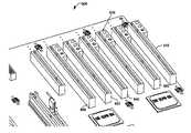
- FIG. 1shows a plurality of slots (bus sockets) 110 - 170 which are in general placed on a mother board 100 for coupling with the bus.
- Sockets 120 - 170are configured to receive standard 64 bit PCI adapter cards whereas socket 110 receives a standard 32 bit PCI card. To be compatible with multiple adapter cards inserted into the system the following principle applies for a PCI bus system. Whenever a user inserts an adapter card into the PCI bus sockets the system bus adapter system runs at the speed defined by the slowest adapter card inserted into the bus system.
- PCI-Xperipheral component interconnect
- PCI, PCI-X and similar bus systemsare defined by the slowest card inserted with regard to their transmission speed.
- Modern computer systemsprovide multiple system busses, for example two independent PCI or PCI-X busses.
- the advantage of having multiple system bussesis that in case two busses are provided, one can be used for slower system adapter cards and one can be used for the faster adapter cards.
- a user not familiar with the technologywill not recognize which adapter card that has already been inserted provides what transmission speed capabilities. Even so a user not skilled in the art is certainly able to extend a computer system by inserting an adapter card, the user might not know which bus is the appropriate bus for the respective adapter card.
- the userwill of course know the speed of the new card to be inserted into the bus system but will probably not remember the respective speed of already inserted cards.
- systemsusually do not indicate which socket is assigned to which of the independent PCI busses.
- U.S. patent application Ser. No. 09/769,799 “RA system and for method for configuring an I/O bus”, filed on Jan. 25, 2001 by David Locklear and Michael Wright and assigned to Dell Corp.describes a remedy to this problem.
- the mother board of a computer systemcomprises light emitting diodes associated to each slot of a PCI bus to indicate whether an adapter card inserted into the slot is limiting the transmission speed on the bus associated to the respective slot.
- this systemstill does not clearly inform a user what specific configuration has been selected to a specific slot.
- valuable real estate area on the mother boardhas to be used to place indicators such as light emitting diodes.
- a computer systemincluding a circuit board comprises a bus system for transmitting address, data and control signals with selectable bus configuration, a plurality of bus sockets on the circuit board for connecting an adapter card with the bus signals, whereby the specification of the adapter card determines the configuration of the associated bus, and an indicator for the bus indicating the configuration, wherein the indicator is integrated in the socket.
- a method of indicating a bus speed within a computer system having a system bus with a plurality of sockets for receiving system adapter cards, whereby the specification of said adapter cards determines the bus configuration, and whereby said socket comprises an integrated indicator,comprises the steps of:
- a socket for a computer bus systemfor connecting a plurality of address, data and control signals to an adapter card which can be plugged into said socket, comprises an indicator for indicating a bus configuration.
- the indicatormay indicate the current bus speed and/or other configuration parameters, such as bus width, transmission modes, etc.
- a socket for the bus systemmay have an integrated driver and control circuit for driving the indicator.
- the indicatorcan be a light diode or a display, such as an alphanumeric or numeric LCD or LED display.
- an activation switch and further indicatorsmay be provided.
- the bus systemcan be a PCI and/or PCI-X bus or any other configurable bus system.
- the socketcan be designed to be equal in size compared to a socket according to the prior art. However, in another embodiment, the socket may be enlarged to receive the indicator.
- the socketmay have left and right side walls, whereby an upper portion of one of the side walls is extended outwards to receive the integrated indicator. In yet another embodiment, only a partial extension of a side wall may be provided to receive the integrated indicator and/or switch.
- the different exemplary embodiments according to the present inventionprovide a user with all necessary information to insert an adapter card in an appropriate bus socket whereby precious real estate on a system board is preserved.
- the socket according to the present inventionmay be equal in size to sockets according to the prior art or designed in a way that the design of a previously designed circuit board which receives such a bus socket does not have to be redesigned. Modification to a bus socket to be able to integrate an indicator can be performed according to the present invention to allow placement of devices close to sockets according to the prior art.
- FIG. 1is a perspective view on a mother board having 7 expansion slots (sockets) according to the prior art
- FIG. 2is a first embodiment of a bus socket according to the present invention
- FIG. 3is a second embodiment of a bus socket according to the present invention.
- FIG. 4is a third embodiment of a bus socket according to the present invention.
- FIG. 5is a perspective view on a mother board having 6 expansion slots (sockets) according to one embodiment of the present invention
- FIG. 6is a perspective view on a mother board having 6 expansion slots (sockets) according to another embodiment of the present invention.
- FIG. 7shows a circuit suitable for driving the indicators according to the first embodiment of the present invention
- FIG. 8shows another circuit suitable for driving the indicators according to the first embodiment of the present invention.
- FIG. 9shows yet another circuit suitable for driving a display according to the second embodiment of the present invention.
- FIG. 2depicts an improved bus socket 200 suitable to be placed on a mother board of a computer system.
- Socket 200comprises a slot 270 including the respective electrical connectors for receiving an adapter card.
- Socket 200has a similar shape compared to a socket according to the prior art as shown in FIG. 1, numeral 120 - 170 .
- the socketcomprises two sidewalls.
- the top face plate 280 of socket 200is extended to the right in comparison to sockets according to the prior art to embed five light emitting diodes (LEDs) 210 , 230 , 240 , 250 , and 260 .
- LEDslight emitting diodes
- LEDs 210 , 230 , 240 , 250 , and 260are placed within the lower portion of face plate 280 .
- the first embodiment according to the present inventionshows engravings 220 below each LED 210 , 230 , 240 , 250 , and 260 indicating the function of the associated LED 210 , 230 , 240 , 250 , and 260 .
- LED 210indicates whether the bus operates in a PCI-X mode.
- the shape of the socketis furthermore optimized to only occupy a minimum of real estate on a main circuit board of a computer system. Therefore, socket 200 comprises a cut off portion 290 within the lower area thus thinning the bottom plate 295 with respect to face plate 280 which directly faces the main circuit board.
- the cut off portion 290is created by the right side wall being phased at about mid height.
- the width of the socket at the bottomis about the same as the width of sockets 120 - 170 shown in FIG. 1 .
- the cut off areacan be even bigger to create a bottom face plate 480 being substantially the same as a that of a standard socket.
- socket 200allows placement of devices in-between two or more sockets as will be explained later.
- LED 230indicates whether PCI-X bus operates with 133 MHz.
- LED 240indicates whether PCI or PCI-X bus operates with 66 MHz
- LED 250indicates whether PCI bus operates with 33 MHz.
- LED 260indicates whether the bus operates in a PCI mode.
- the socketis designed to either include the driver circuits for the LEDS and receive all necessary signals from the slot connectors (not shown) or provide additional contacts to supply the LEDs 210 , 230 , 240 , 250 , and 260 .
- FIG. 3depicts a another embodiment of the present invention.
- Numeral 300designates the socket suitable to receive an adapter card within a slot 310 .
- slot 310comprises all necessary connectors to supply an adapter card with all necessary signals of a respective bus, such as a PCI-X bus.
- Socket 300comprises a top face plate 350 which is extended to provide space for a display 320 .
- the shape of the socketis optimized to only occupy a minimum of real estate on a main circuit board of a computer system. Therefore, socket 300 comprises a cut off portion 370 as described in combination with FIG. 2 within the lower area thus thinning the bottom plate 380 which directly faces the main circuit board.
- socket 300allows placement of devices in-between two or more sockets as will be explained later.
- Display 320can be a numerical or alpha-numerical display of the LED or LCD type. Display 320 provides enough characters to be able to indicate different bus modes according to the respectively used bus standard. In addition, an engraving 330 may be provided to indicate a unit, such as “MHz”, as a unit of a variable parameter. If more than one parameter of an applied bus standard varies multiple displays may be provided. Furthermore, socket 300 provides an optional embedded switch 360 placed in the upper right corner of top face plate 350 . Switch 360 can serve to provide a so-called hot-plug feature as will be explained later. Again, socket 300 is designed to either include the driver circuits for the display 320 and switch 360 , and receive all necessary signals from the slot connectors (not shown) or provide additional contacts to supply the switch 360 and display 320 with respective signals.
- the systemchecks the bus requirements for this card. if the card matches the current setting no mode or frequency change will occur. However, if the card can only operate a lower bus speed and/or with a different bus mode setting (for example, PCI or PCI-X mode), the entire bus will be reconfigured to allow this card to operate properly.
- a different bus mode settingfor example, PCI or PCI-X mode
- the embodiment shown in FIG. 3indicates with a first character whether the bus operates as a PCI-X bus or as a PCI bus by showing either a “X” or a space character.
- the following charactersare used to indicate the current bus speed. For example, “133 MHz” as shown in FIG. 3 .
- the displaymay toggle between different display information. For example, the display may show the bus speed as “133 M” for a predefined period of time followed by the display “X-64B” indicating PCI-X bus mode which operates with a 64 bit wide bus and then display the bus speed again, etc. In this embodiment no engraving is needed.
- switch 360provides more functionality in combination with display 320 .
- Switch 360serves to activate the hot-plug feature. When activated, a card can either be inserted, removed, or exchanged. To this end, the user operates switch 360 .
- the computer systemcomprises respective circuitry that deactivates the power supply for the respective socket.
- bus signal linesare switched to either a floating state or are deactivated so that removing or inserting an adapter card does not destroy or interfere with any sensitive electronic component on the mother board or the respective adapter card.
- Display 320can now display the status of the respective slot. For example, display 320 can display “FREE ” or “OFF” indicating that a respective card can be removed or inserted. In addition, display 320 can still show all other parameters with respective time gaps as explained above to inform the user about the bus parameters.
- the switchcan have locked positions or operate as a button switch.
- FIG. 4depicts yet another embodiment of the present invention.
- Numeral 400indicates a socket according to this embodiment.
- the shown socket 400comprises a slot for receiving an adapter card.
- the bottom portion 460 of the socketis designed in accordance with the standard sockets known in the prior art.
- the top portioncomprises an enlarged area with a top face plate 450 .
- the bottom parthas a cut off section 470 thus thinning the part of the socket which faces a mother board as explained with regard to FIG. 2 . Therefore, bottom face plate 480 is smaller than top face plate 450 .
- Top face plate 450embeds two LEDs 430 and 440 and a switch 420 .
- switch 420may be a push button or on/off switch.
- LEDs 430 and 440indicate the operation mode of the respective socket. Whenever a user pushes switch 320 the system processor/baseboard management controller (not shown) is notified that a card is to be inserted on a bus slot or removed from the bus slot. Furthermore, the system controller is informed that the power is to be toggled for the respective bus slot. To indicate this mode for the user, the LEDs 430 and 440 are used. For example, LED 440 is a green LED which is lit whenever the system is ready to operate. If it is turned off or flashing this indicates that the power has been toggled and a card may be removed or inserted. Furthermore, LED 430 might be used to indicate any failure or malfunction while removing or installing a card. Therefore, LED can be for example an amber colored LED.
- a single LEDcan be used which then is a LED of the bi-color type. If an error occurs during hardware or software installation this LED can signal this to the user by changing its color, for example, from green to red. Flashing can be used to indicate a hot-plug mode.
- the socketis again designed to either include the driver circuits for the LEDs 430 , 440 and switch 420 , and receive all necessary signals from the slot connectors (not shown) or provide additional contacts to supply the LEDs 430 , 440 and switch 420 .
- FIG. 5shows a plurality of bus sockets according to the embodiment of FIG. 4 placed commonly on a mother board of a computer system.
- the improved socketsdo not require a lot of additional real estate on the mother board.
- the cut off portion 470allows placement of devices on the mother board. Thus, no or only minimal redesign of a mother board might be necessary.
- FIG. 6shows a plurality of bus sockets according to a combination of the embodiments of FIG. 2 and 4 placed commonly on a mother board of a computer system.
- the design of each socketcombines the features of the above mentioned embodiments.
- each socketcomprises a plurality of LEDs in the lower area of 610 of the face plate 620 and the hotplug indicators and switch placed in the upper area 630 of the right side of face plate 620 .
- the improved socketsdo not require a lot of additional real estate on the mother board.
- the cut off portion 670allows placement of devices on the mother board. Thus, no or only minimal re-design of a mother board might be necessary.
- FIG. 7shows a first embodiment of a control circuit capable of driving the indicator LEDs.
- Appropriate status signals 701are generated by the system processor/baseboard management controller (not shown) or can be derived directly from the bus signals.
- the status of the busmay be encoded in a binary code transmitted through lines 701 .
- This codeis fed to a decode unit 700 .
- Decode unit 700comprises five outputs which are coupled to inputs of five flip-flops 720 , 730 , 740 , 750 , and 760 .
- a set signal 710is provided and fed to set inputs of flip-flops 720 , 730 , 740 , 750 , and 760 .
- Each flip-flop 720 , 730 , 740 , 750 , and 760comprises an output which is coupled with an associated driver 725 , 735 , 745 , 755 , and 765 .
- Each drivercontrols an associated LED 726 , 736 , 746 , 756 , and 766 , respectively.
- Signal lines 701carry an encoded information about the current bus status. For example, one line can indicate whether the bus is operating in a PCI or a PCI-X mode. The other two lines can indicate four different bus speeds, for example, 33 MHz, 66 MHz, 100 MHz, and 133 MHz. In the present embodiment, only three bus speeds are used, namely 33 MHz, 66 MHz, and 133 MHz.
- Decode unit 700decodes this information and provides flip-flops 720 , 730 , 740 , 750 , and 760 with the respective signals.
- Set signal 710is either activated every time a status change takes place or, for example, periodically.
- Set signal 710indicates to flipflops 720 , 730 , 740 , 750 , and 760 that the information provided at each input has to be transferred into the respective flip-flop register.
- the output of each flip-flop 720 , 730 , 740 , 750 , and 760carries the content of the flipflop register and respective LEDs 726 , 736 , 746 , 756 , and 766 are driven with a respective signal through drivers 725 , 735 , 745 , 755 , and 765 , respectively.
- This control circuitis designed to store the current status, even if power supply lines of the bus connectors are turned off to allow inserting or exchanging of expansion cards.
- FIG. 8shows another LED driver/control circuit suitable to be integrated into a socket according to the embodiments of the present invention.
- Numeral 800designates the slot contacts within the socket of a bus system.
- Signal 810is used to determine the bus speed and can be, for example, a system clock signal provided on the bus. This signal is fed to the input of a bus speed sensor unit 840 .
- a busmight provide different signal lines digitally indicating the current bus speed. In such an environment a decoder is used rather than a bus speed sensor.
- Bus speed sensor 840comprises circuitry to detect the different clock signal frequencies and drives respective LEDs 844 , 845 , and 856 through associated drivers 841 , 842 , and 843 , respectively.
- two signals 820 and 830are used to determine the bus mode. Any other suitable signal or signals can be used to determine the current mode.
- These signals 820 and 830are fed to mode sensor unit 850 which drives respective LEDs 853 and 854 .
- modewill be either a PCI mode or a PCI-X mode. Therefore only one output signal is used to drive the LEDs 853 and 854 .
- Driver 851drives LED 853 and inverter 852 drives LED 854 . Both, driver 851 and inverter 852 receive the output signal from mode sensor unit 850 .
- FIG. 9depicts a block diagram showing a suitable control circuit for the second embodiment according to the present invention.
- Status lines 900are either provided by the bus itself or by a system processor/baseboard management controller (not shown). These signals are fed to a display driver unit 910 which encodes the information carried on signal lines 900 and drives display unit 920 .
- Display unit 920can be a liquid crystal display (LCD) or a LED display.
- Display driver 910generates all necessary signals to control and drive such a display.
- the display drivermay be embedded in each socket of the bus system that comprises a display or be part of the system processor/baseboard management controller (not shown). In this case additional lines are provided for the socket.
- all indicators and their respective control and driver circuitryare integrated in the respective socket.
- existing main boards or mother boardscan be used without changing the layout and design.
- a less expensive solutioncan provide a common driver and control unit within the system processor/baseboard management controller and provide additional signal lines for the socket which directly drive each individual indicator, such as LEDs, LCDs, etc.
- the exemplary embodiments of the present inventioninform a user precisely about the status of each slot. A user will therefore readily see which slots are suitable for a respective adapter card.
- a PCI-X busthat is designed for PCI-X 133 MHz adapter cards is running at full speed and is optimized when only PCI-X 133 MHz adapter cards are installed in that bus.
- the improved bus socketsindicate the status to a user thus providing the ability of maintaining a desired mode for a specific bus in a computer system.
Landscapes
- Engineering & Computer Science (AREA)
- Theoretical Computer Science (AREA)
- General Engineering & Computer Science (AREA)
- Computer Hardware Design (AREA)
- Physics & Mathematics (AREA)
- General Physics & Mathematics (AREA)
- Power Engineering (AREA)
- Human Computer Interaction (AREA)
- Debugging And Monitoring (AREA)
Abstract
Description
Claims (40)
Priority Applications (1)
| Application Number | Priority Date | Filing Date | Title |
|---|---|---|---|
| US09/896,215US6820156B1 (en) | 2001-06-29 | 2001-06-29 | Computer system with bus socket showing configured mode |
Applications Claiming Priority (1)
| Application Number | Priority Date | Filing Date | Title |
|---|---|---|---|
| US09/896,215US6820156B1 (en) | 2001-06-29 | 2001-06-29 | Computer system with bus socket showing configured mode |
Publications (2)
| Publication Number | Publication Date |
|---|---|
| US20040225798A1 US20040225798A1 (en) | 2004-11-11 |
| US6820156B1true US6820156B1 (en) | 2004-11-16 |
Family
ID=33419053
Family Applications (1)
| Application Number | Title | Priority Date | Filing Date |
|---|---|---|---|
| US09/896,215Expired - LifetimeUS6820156B1 (en) | 2001-06-29 | 2001-06-29 | Computer system with bus socket showing configured mode |
Country Status (1)
| Country | Link |
|---|---|
| US (1) | US6820156B1 (en) |
Cited By (10)
| Publication number | Priority date | Publication date | Assignee | Title |
|---|---|---|---|---|
| US20040003155A1 (en)* | 2002-07-01 | 2004-01-01 | Compaq Information Technologies Group, L.P. A Delaware Corporation | Method and system of indicating current operating speeds of expansion slots of a computer system |
| US20040034875A1 (en)* | 2002-04-03 | 2004-02-19 | Brian Bulkowski | Method and apparatus for transmitting data in a data stream |
| US7035954B1 (en)* | 2003-04-03 | 2006-04-25 | Advanced Micro Devices, Inc. | Automatic bus speed and mode balancing after hot-plug events on hot-plug driver |
| US7272668B1 (en)* | 2003-06-26 | 2007-09-18 | Emc Corporation | System having backplane performance capability selection logic |
| US20090023320A1 (en)* | 2007-07-20 | 2009-01-22 | Numatics, Incorporated | Modular electrical bus system |
| WO2010050940A1 (en)* | 2008-10-29 | 2010-05-06 | Hewlett-Packard Development Company, L.P. | Component installation guidance |
| US20100122841A1 (en)* | 2008-11-14 | 2010-05-20 | Samsung Electronics Co., Ltd. | Printed circuit board assembly of electronic appliance |
| US8687350B2 (en)* | 2011-05-11 | 2014-04-01 | Ez-Tech Corp | Motherboard and case with hidden internal connectors |
| US10615549B2 (en) | 2016-09-01 | 2020-04-07 | Seagate Technology Llc | Configured port-width indication for ganged-style connectors |
| WO2022088763A1 (en)* | 2020-11-02 | 2022-05-05 | 深圳市洲明科技股份有限公司 | Display screen having design compatible with flash memory circuit and smart module |
Families Citing this family (1)
| Publication number | Priority date | Publication date | Assignee | Title |
|---|---|---|---|---|
| CN103076858A (en)* | 2011-10-25 | 2013-05-01 | 鸿富锦精密工业(深圳)有限公司 | Expansion card and main board for supporting expansion card |
Citations (9)
| Publication number | Priority date | Publication date | Assignee | Title |
|---|---|---|---|---|
| US3891898A (en)* | 1973-10-11 | 1975-06-24 | Augat Inc | Panel board mounting and interconnection system for electronic logic circuitry |
| US5559965A (en)* | 1994-09-01 | 1996-09-24 | Intel Corporation | Input/output adapter cards having a plug and play compliant mode and an assigned resources mode |
| US5611057A (en) | 1994-10-06 | 1997-03-11 | Dell Usa, L.P. | Computer system modular add-in daughter card for an adapter card which also functions as an independent add-in card |
| US5623691A (en) | 1994-11-14 | 1997-04-22 | Compaq Computer Corporation | PCI bus hard disk activity LED circuit |
| US5657455A (en) | 1994-09-07 | 1997-08-12 | Adaptec, Inc. | Status indicator for a host adapter |
| US5724529A (en)* | 1995-11-22 | 1998-03-03 | Cirrus Logic, Inc. | Computer system with multiple PC card controllers and a method of controlling I/O transfers in the system |
| US5841287A (en)* | 1997-02-26 | 1998-11-24 | Advanced Micro Devices, Inc. | System for detecting motherboard operation to ensure compatibility of a microprocessor to be coupled thereto |
| US6122693A (en) | 1997-11-14 | 2000-09-19 | Lucent Technologies, Inc. | PCI bus utilization diagnostic monitor |
| US6134621A (en) | 1998-06-05 | 2000-10-17 | International Business Machines Corporation | Variable slot configuration for multi-speed bus |
- 2001
- 2001-06-29USUS09/896,215patent/US6820156B1/ennot_activeExpired - Lifetime
Patent Citations (10)
| Publication number | Priority date | Publication date | Assignee | Title |
|---|---|---|---|---|
| US3891898A (en)* | 1973-10-11 | 1975-06-24 | Augat Inc | Panel board mounting and interconnection system for electronic logic circuitry |
| US5559965A (en)* | 1994-09-01 | 1996-09-24 | Intel Corporation | Input/output adapter cards having a plug and play compliant mode and an assigned resources mode |
| US5657455A (en) | 1994-09-07 | 1997-08-12 | Adaptec, Inc. | Status indicator for a host adapter |
| US5611057A (en) | 1994-10-06 | 1997-03-11 | Dell Usa, L.P. | Computer system modular add-in daughter card for an adapter card which also functions as an independent add-in card |
| US5623691A (en) | 1994-11-14 | 1997-04-22 | Compaq Computer Corporation | PCI bus hard disk activity LED circuit |
| US5761527A (en) | 1994-11-14 | 1998-06-02 | Compaq Computer Corporation | PCI bus hard disk activity LED circuit |
| US5724529A (en)* | 1995-11-22 | 1998-03-03 | Cirrus Logic, Inc. | Computer system with multiple PC card controllers and a method of controlling I/O transfers in the system |
| US5841287A (en)* | 1997-02-26 | 1998-11-24 | Advanced Micro Devices, Inc. | System for detecting motherboard operation to ensure compatibility of a microprocessor to be coupled thereto |
| US6122693A (en) | 1997-11-14 | 2000-09-19 | Lucent Technologies, Inc. | PCI bus utilization diagnostic monitor |
| US6134621A (en) | 1998-06-05 | 2000-10-17 | International Business Machines Corporation | Variable slot configuration for multi-speed bus |
Non-Patent Citations (1)
| Title |
|---|
| U.S. Pending application Ser. No. 09/769,799 entitled "A System and Method for Configuring an I/O Bus" David A. Locklear et al., Assignee-Dell USA L.P, filed Jan. 25, 2001. |
Cited By (17)
| Publication number | Priority date | Publication date | Assignee | Title |
|---|---|---|---|---|
| US20040034875A1 (en)* | 2002-04-03 | 2004-02-19 | Brian Bulkowski | Method and apparatus for transmitting data in a data stream |
| US20040003155A1 (en)* | 2002-07-01 | 2004-01-01 | Compaq Information Technologies Group, L.P. A Delaware Corporation | Method and system of indicating current operating speeds of expansion slots of a computer system |
| US7035954B1 (en)* | 2003-04-03 | 2006-04-25 | Advanced Micro Devices, Inc. | Automatic bus speed and mode balancing after hot-plug events on hot-plug driver |
| US7272668B1 (en)* | 2003-06-26 | 2007-09-18 | Emc Corporation | System having backplane performance capability selection logic |
| US20100248556A1 (en)* | 2007-07-20 | 2010-09-30 | Numatics, Incorporated | Modular Electrical Bus System |
| US7753740B2 (en)* | 2007-07-20 | 2010-07-13 | Numatics, Incorporated | Modular electrical bus system |
| US20090023320A1 (en)* | 2007-07-20 | 2009-01-22 | Numatics, Incorporated | Modular electrical bus system |
| US7896711B2 (en) | 2007-07-20 | 2011-03-01 | Numatics, Incorporated | Modular electrical bus system |
| US7967646B2 (en) | 2007-07-20 | 2011-06-28 | Numatics, Incorporated | Modular electrical bus system |
| USRE48517E1 (en) | 2007-07-20 | 2021-04-13 | Asco, L.P. | Modular electrical bus system |
| WO2010050940A1 (en)* | 2008-10-29 | 2010-05-06 | Hewlett-Packard Development Company, L.P. | Component installation guidance |
| US8760312B2 (en) | 2008-10-29 | 2014-06-24 | Hewlett-Packard Development Company, L.P. | Component installation guidance |
| US20100122841A1 (en)* | 2008-11-14 | 2010-05-20 | Samsung Electronics Co., Ltd. | Printed circuit board assembly of electronic appliance |
| US8130510B2 (en)* | 2008-11-14 | 2012-03-06 | Samsung Electronics Co., Ltd. | Printed circuit board assembly of electronic appliance |
| US8687350B2 (en)* | 2011-05-11 | 2014-04-01 | Ez-Tech Corp | Motherboard and case with hidden internal connectors |
| US10615549B2 (en) | 2016-09-01 | 2020-04-07 | Seagate Technology Llc | Configured port-width indication for ganged-style connectors |
| WO2022088763A1 (en)* | 2020-11-02 | 2022-05-05 | 深圳市洲明科技股份有限公司 | Display screen having design compatible with flash memory circuit and smart module |
Also Published As
| Publication number | Publication date |
|---|---|
| US20040225798A1 (en) | 2004-11-11 |
Similar Documents
| Publication | Publication Date | Title |
|---|---|---|
| US6725318B1 (en) | Automated selection between a USB and PS/2 interface for connecting a keyboard to a computer | |
| US5440755A (en) | Computer system with a processor-direct universal bus connector and interchangeable bus translator | |
| KR100240921B1 (en) | Computer system including system bus and method of device connection by system bus | |
| US8643657B2 (en) | Field changeable rendering system for a computing device | |
| US7024510B2 (en) | Supporting a host-to-input/output (I/O) bridge | |
| US6820156B1 (en) | Computer system with bus socket showing configured mode | |
| JPH11175456A (en) | Computer system | |
| US6216184B1 (en) | Extended riser for implementing a cableless front panel input/output | |
| EP0778532A2 (en) | An information processing apparatus | |
| US20070143058A1 (en) | System and method for testing an input/output functional board | |
| EP1181638B1 (en) | Method and apparatus for maintaining load balance on a graphics bus when an upgrade device is installed | |
| KR20030036364A (en) | Structure for modular computer | |
| KR20010088317A (en) | Computer system state monitor for gating power-on control | |
| CN101221458B (en) | Devices with field-replaceable graphics cards | |
| US6092134A (en) | Method and apparatus for locking out a processor in a computer system with a bus that is improperly terminated | |
| KR100499585B1 (en) | Union type main board | |
| KR100451795B1 (en) | Process apparatus hot swap of compact PCI | |
| US7757031B2 (en) | Data transmission coordinating method and system | |
| KR100207321B1 (en) | Computer with output port for power supply | |
| JP2007233878A (en) | Information processor | |
| KR200239759Y1 (en) | Union type main board | |
| KR200319924Y1 (en) | Structure for modular computer | |
| JP2007233879A (en) | Information processor | |
| CN100356297C (en) | Computer system and control method of the same | |
| TW202526897A (en) | Panel connection device and judgement method of panel devices |
Legal Events
| Date | Code | Title | Description |
|---|---|---|---|
| AS | Assignment | Owner name:DELL PRODUCTS L.P., TEXAS Free format text:ASSIGNMENT OF ASSIGNORS INTEREST;ASSIGNORS:MILLER, KEVIN L.;SCHMITT, TY R.;REEL/FRAME:011961/0763 Effective date:20010625 | |
| FEPP | Fee payment procedure | Free format text:PAYER NUMBER DE-ASSIGNED (ORIGINAL EVENT CODE: RMPN); ENTITY STATUS OF PATENT OWNER: LARGE ENTITY Free format text:PAYOR NUMBER ASSIGNED (ORIGINAL EVENT CODE: ASPN); ENTITY STATUS OF PATENT OWNER: LARGE ENTITY | |
| STCF | Information on status: patent grant | Free format text:PATENTED CASE | |
| FEPP | Fee payment procedure | Free format text:PAYER NUMBER DE-ASSIGNED (ORIGINAL EVENT CODE: RMPN); ENTITY STATUS OF PATENT OWNER: LARGE ENTITY Free format text:PAYOR NUMBER ASSIGNED (ORIGINAL EVENT CODE: ASPN); ENTITY STATUS OF PATENT OWNER: LARGE ENTITY | |
| FPAY | Fee payment | Year of fee payment:4 | |
| FPAY | Fee payment | Year of fee payment:8 | |
| AS | Assignment | Owner name:BANK OF AMERICA, N.A., AS ADMINISTRATIVE AGENT, TE Free format text:PATENT SECURITY AGREEMENT (ABL);ASSIGNORS:DELL INC.;APPASSURE SOFTWARE, INC.;ASAP SOFTWARE EXPRESS, INC.;AND OTHERS;REEL/FRAME:031898/0001 Effective date:20131029 Owner name:BANK OF AMERICA, N.A., AS ADMINISTRATIVE AGENT, TEXAS Free format text:PATENT SECURITY AGREEMENT (ABL);ASSIGNORS:DELL INC.;APPASSURE SOFTWARE, INC.;ASAP SOFTWARE EXPRESS, INC.;AND OTHERS;REEL/FRAME:031898/0001 Effective date:20131029 Owner name:BANK OF AMERICA, N.A., AS COLLATERAL AGENT, NORTH CAROLINA Free format text:PATENT SECURITY AGREEMENT (TERM LOAN);ASSIGNORS:DELL INC.;APPASSURE SOFTWARE, INC.;ASAP SOFTWARE EXPRESS, INC.;AND OTHERS;REEL/FRAME:031899/0261 Effective date:20131029 Owner name:BANK OF NEW YORK MELLON TRUST COMPANY, N.A., AS FIRST LIEN COLLATERAL AGENT, TEXAS Free format text:PATENT SECURITY AGREEMENT (NOTES);ASSIGNORS:APPASSURE SOFTWARE, INC.;ASAP SOFTWARE EXPRESS, INC.;BOOMI, INC.;AND OTHERS;REEL/FRAME:031897/0348 Effective date:20131029 Owner name:BANK OF NEW YORK MELLON TRUST COMPANY, N.A., AS FI Free format text:PATENT SECURITY AGREEMENT (NOTES);ASSIGNORS:APPASSURE SOFTWARE, INC.;ASAP SOFTWARE EXPRESS, INC.;BOOMI, INC.;AND OTHERS;REEL/FRAME:031897/0348 Effective date:20131029 Owner name:BANK OF AMERICA, N.A., AS COLLATERAL AGENT, NORTH Free format text:PATENT SECURITY AGREEMENT (TERM LOAN);ASSIGNORS:DELL INC.;APPASSURE SOFTWARE, INC.;ASAP SOFTWARE EXPRESS, INC.;AND OTHERS;REEL/FRAME:031899/0261 Effective date:20131029 | |
| FPAY | Fee payment | Year of fee payment:12 | |
| AS | Assignment | Owner name:DELL PRODUCTS L.P., TEXAS Free format text:RELEASE BY SECURED PARTY;ASSIGNOR:BANK OF AMERICA, N.A., AS ADMINISTRATIVE AGENT;REEL/FRAME:040065/0216 Effective date:20160907 Owner name:DELL INC., TEXAS Free format text:RELEASE BY SECURED PARTY;ASSIGNOR:BANK OF AMERICA, N.A., AS ADMINISTRATIVE AGENT;REEL/FRAME:040065/0216 Effective date:20160907 Owner name:APPASSURE SOFTWARE, INC., VIRGINIA Free format text:RELEASE BY SECURED PARTY;ASSIGNOR:BANK OF AMERICA, N.A., AS ADMINISTRATIVE AGENT;REEL/FRAME:040065/0216 Effective date:20160907 Owner name:DELL USA L.P., TEXAS Free format text:RELEASE BY SECURED PARTY;ASSIGNOR:BANK OF AMERICA, N.A., AS ADMINISTRATIVE AGENT;REEL/FRAME:040065/0216 Effective date:20160907 Owner name:CREDANT TECHNOLOGIES, INC., TEXAS Free format text:RELEASE BY SECURED PARTY;ASSIGNOR:BANK OF AMERICA, N.A., AS ADMINISTRATIVE AGENT;REEL/FRAME:040065/0216 Effective date:20160907 Owner name:FORCE10 NETWORKS, INC., CALIFORNIA Free format text:RELEASE BY SECURED PARTY;ASSIGNOR:BANK OF AMERICA, N.A., AS ADMINISTRATIVE AGENT;REEL/FRAME:040065/0216 Effective date:20160907 Owner name:DELL MARKETING L.P., TEXAS Free format text:RELEASE BY SECURED PARTY;ASSIGNOR:BANK OF AMERICA, N.A., AS ADMINISTRATIVE AGENT;REEL/FRAME:040065/0216 Effective date:20160907 Owner name:COMPELLANT TECHNOLOGIES, INC., MINNESOTA Free format text:RELEASE BY SECURED PARTY;ASSIGNOR:BANK OF AMERICA, N.A., AS ADMINISTRATIVE AGENT;REEL/FRAME:040065/0216 Effective date:20160907 Owner name:ASAP SOFTWARE EXPRESS, INC., ILLINOIS Free format text:RELEASE BY SECURED PARTY;ASSIGNOR:BANK OF AMERICA, N.A., AS ADMINISTRATIVE AGENT;REEL/FRAME:040065/0216 Effective date:20160907 Owner name:WYSE TECHNOLOGY L.L.C., CALIFORNIA Free format text:RELEASE BY SECURED PARTY;ASSIGNOR:BANK OF AMERICA, N.A., AS ADMINISTRATIVE AGENT;REEL/FRAME:040065/0216 Effective date:20160907 Owner name:PEROT SYSTEMS CORPORATION, TEXAS Free format text:RELEASE BY SECURED PARTY;ASSIGNOR:BANK OF AMERICA, N.A., AS ADMINISTRATIVE AGENT;REEL/FRAME:040065/0216 Effective date:20160907 Owner name:DELL SOFTWARE INC., CALIFORNIA Free format text:RELEASE BY SECURED PARTY;ASSIGNOR:BANK OF AMERICA, N.A., AS ADMINISTRATIVE AGENT;REEL/FRAME:040065/0216 Effective date:20160907 Owner name:SECUREWORKS, INC., GEORGIA Free format text:RELEASE BY SECURED PARTY;ASSIGNOR:BANK OF AMERICA, N.A., AS ADMINISTRATIVE AGENT;REEL/FRAME:040065/0216 Effective date:20160907 | |
| AS | Assignment | Owner name:PEROT SYSTEMS CORPORATION, TEXAS Free format text:RELEASE BY SECURED PARTY;ASSIGNOR:BANK OF AMERICA, N.A., AS COLLATERAL AGENT;REEL/FRAME:040040/0001 Effective date:20160907 Owner name:WYSE TECHNOLOGY L.L.C., CALIFORNIA Free format text:RELEASE BY SECURED PARTY;ASSIGNOR:BANK OF AMERICA, N.A., AS COLLATERAL AGENT;REEL/FRAME:040040/0001 Effective date:20160907 Owner name:DELL MARKETING L.P., TEXAS Free format text:RELEASE BY SECURED PARTY;ASSIGNOR:BANK OF AMERICA, N.A., AS COLLATERAL AGENT;REEL/FRAME:040040/0001 Effective date:20160907 Owner name:COMPELLENT TECHNOLOGIES, INC., MINNESOTA Free format text:RELEASE BY SECURED PARTY;ASSIGNOR:BANK OF AMERICA, N.A., AS COLLATERAL AGENT;REEL/FRAME:040040/0001 Effective date:20160907 Owner name:SECUREWORKS, INC., GEORGIA Free format text:RELEASE BY SECURED PARTY;ASSIGNOR:BANK OF AMERICA, N.A., AS COLLATERAL AGENT;REEL/FRAME:040040/0001 Effective date:20160907 Owner name:FORCE10 NETWORKS, INC., CALIFORNIA Free format text:RELEASE BY SECURED PARTY;ASSIGNOR:BANK OF AMERICA, N.A., AS COLLATERAL AGENT;REEL/FRAME:040040/0001 Effective date:20160907 Owner name:ASAP SOFTWARE EXPRESS, INC., ILLINOIS Free format text:RELEASE BY SECURED PARTY;ASSIGNOR:BANK OF AMERICA, N.A., AS COLLATERAL AGENT;REEL/FRAME:040040/0001 Effective date:20160907 Owner name:CREDANT TECHNOLOGIES, INC., TEXAS Free format text:RELEASE BY SECURED PARTY;ASSIGNOR:BANK OF AMERICA, N.A., AS COLLATERAL AGENT;REEL/FRAME:040040/0001 Effective date:20160907 Owner name:DELL PRODUCTS L.P., TEXAS Free format text:RELEASE BY SECURED PARTY;ASSIGNOR:BANK OF AMERICA, N.A., AS COLLATERAL AGENT;REEL/FRAME:040040/0001 Effective date:20160907 Owner name:APPASSURE SOFTWARE, INC., VIRGINIA Free format text:RELEASE BY SECURED PARTY;ASSIGNOR:BANK OF AMERICA, N.A., AS COLLATERAL AGENT;REEL/FRAME:040040/0001 Effective date:20160907 Owner name:DELL INC., TEXAS Free format text:RELEASE BY SECURED PARTY;ASSIGNOR:BANK OF AMERICA, N.A., AS COLLATERAL AGENT;REEL/FRAME:040040/0001 Effective date:20160907 Owner name:DELL SOFTWARE INC., CALIFORNIA Free format text:RELEASE BY SECURED PARTY;ASSIGNOR:BANK OF AMERICA, N.A., AS COLLATERAL AGENT;REEL/FRAME:040040/0001 Effective date:20160907 Owner name:DELL USA L.P., TEXAS Free format text:RELEASE BY SECURED PARTY;ASSIGNOR:BANK OF AMERICA, N.A., AS COLLATERAL AGENT;REEL/FRAME:040040/0001 Effective date:20160907 Owner name:ASAP SOFTWARE EXPRESS, INC., ILLINOIS Free format text:RELEASE BY SECURED PARTY;ASSIGNOR:BANK OF NEW YORK MELLON TRUST COMPANY, N.A., AS COLLATERAL AGENT;REEL/FRAME:040065/0618 Effective date:20160907 Owner name:DELL MARKETING L.P., TEXAS Free format text:RELEASE BY SECURED PARTY;ASSIGNOR:BANK OF NEW YORK MELLON TRUST COMPANY, N.A., AS COLLATERAL AGENT;REEL/FRAME:040065/0618 Effective date:20160907 Owner name:PEROT SYSTEMS CORPORATION, TEXAS Free format text:RELEASE BY SECURED PARTY;ASSIGNOR:BANK OF NEW YORK MELLON TRUST COMPANY, N.A., AS COLLATERAL AGENT;REEL/FRAME:040065/0618 Effective date:20160907 Owner name:SECUREWORKS, INC., GEORGIA Free format text:RELEASE BY SECURED PARTY;ASSIGNOR:BANK OF NEW YORK MELLON TRUST COMPANY, N.A., AS COLLATERAL AGENT;REEL/FRAME:040065/0618 Effective date:20160907 Owner name:FORCE10 NETWORKS, INC., CALIFORNIA Free format text:RELEASE BY SECURED PARTY;ASSIGNOR:BANK OF NEW YORK MELLON TRUST COMPANY, N.A., AS COLLATERAL AGENT;REEL/FRAME:040065/0618 Effective date:20160907 Owner name:DELL INC., TEXAS Free format text:RELEASE BY SECURED PARTY;ASSIGNOR:BANK OF NEW YORK MELLON TRUST COMPANY, N.A., AS COLLATERAL AGENT;REEL/FRAME:040065/0618 Effective date:20160907 Owner name:COMPELLENT TECHNOLOGIES, INC., MINNESOTA Free format text:RELEASE BY SECURED PARTY;ASSIGNOR:BANK OF NEW YORK MELLON TRUST COMPANY, N.A., AS COLLATERAL AGENT;REEL/FRAME:040065/0618 Effective date:20160907 Owner name:APPASSURE SOFTWARE, INC., VIRGINIA Free format text:RELEASE BY SECURED PARTY;ASSIGNOR:BANK OF NEW YORK MELLON TRUST COMPANY, N.A., AS COLLATERAL AGENT;REEL/FRAME:040065/0618 Effective date:20160907 Owner name:DELL SOFTWARE INC., CALIFORNIA Free format text:RELEASE BY SECURED PARTY;ASSIGNOR:BANK OF NEW YORK MELLON TRUST COMPANY, N.A., AS COLLATERAL AGENT;REEL/FRAME:040065/0618 Effective date:20160907 Owner name:DELL PRODUCTS L.P., TEXAS Free format text:RELEASE BY SECURED PARTY;ASSIGNOR:BANK OF NEW YORK MELLON TRUST COMPANY, N.A., AS COLLATERAL AGENT;REEL/FRAME:040065/0618 Effective date:20160907 Owner name:CREDANT TECHNOLOGIES, INC., TEXAS Free format text:RELEASE BY SECURED PARTY;ASSIGNOR:BANK OF NEW YORK MELLON TRUST COMPANY, N.A., AS COLLATERAL AGENT;REEL/FRAME:040065/0618 Effective date:20160907 Owner name:WYSE TECHNOLOGY L.L.C., CALIFORNIA Free format text:RELEASE BY SECURED PARTY;ASSIGNOR:BANK OF NEW YORK MELLON TRUST COMPANY, N.A., AS COLLATERAL AGENT;REEL/FRAME:040065/0618 Effective date:20160907 Owner name:DELL USA L.P., TEXAS Free format text:RELEASE BY SECURED PARTY;ASSIGNOR:BANK OF NEW YORK MELLON TRUST COMPANY, N.A., AS COLLATERAL AGENT;REEL/FRAME:040065/0618 Effective date:20160907 | |
| AS | Assignment | Owner name:CREDIT SUISSE AG, CAYMAN ISLANDS BRANCH, AS COLLATERAL AGENT, NORTH CAROLINA Free format text:SECURITY AGREEMENT;ASSIGNORS:ASAP SOFTWARE EXPRESS, INC.;AVENTAIL LLC;CREDANT TECHNOLOGIES, INC.;AND OTHERS;REEL/FRAME:040134/0001 Effective date:20160907 Owner name:THE BANK OF NEW YORK MELLON TRUST COMPANY, N.A., AS NOTES COLLATERAL AGENT, TEXAS Free format text:SECURITY AGREEMENT;ASSIGNORS:ASAP SOFTWARE EXPRESS, INC.;AVENTAIL LLC;CREDANT TECHNOLOGIES, INC.;AND OTHERS;REEL/FRAME:040136/0001 Effective date:20160907 Owner name:CREDIT SUISSE AG, CAYMAN ISLANDS BRANCH, AS COLLAT Free format text:SECURITY AGREEMENT;ASSIGNORS:ASAP SOFTWARE EXPRESS, INC.;AVENTAIL LLC;CREDANT TECHNOLOGIES, INC.;AND OTHERS;REEL/FRAME:040134/0001 Effective date:20160907 Owner name:THE BANK OF NEW YORK MELLON TRUST COMPANY, N.A., A Free format text:SECURITY AGREEMENT;ASSIGNORS:ASAP SOFTWARE EXPRESS, INC.;AVENTAIL LLC;CREDANT TECHNOLOGIES, INC.;AND OTHERS;REEL/FRAME:040136/0001 Effective date:20160907 | |
| AS | Assignment | Owner name:THE BANK OF NEW YORK MELLON TRUST COMPANY, N.A., T Free format text:SECURITY AGREEMENT;ASSIGNORS:CREDANT TECHNOLOGIES, INC.;DELL INTERNATIONAL L.L.C.;DELL MARKETING L.P.;AND OTHERS;REEL/FRAME:049452/0223 Effective date:20190320 Owner name:THE BANK OF NEW YORK MELLON TRUST COMPANY, N.A., TEXAS Free format text:SECURITY AGREEMENT;ASSIGNORS:CREDANT TECHNOLOGIES, INC.;DELL INTERNATIONAL L.L.C.;DELL MARKETING L.P.;AND OTHERS;REEL/FRAME:049452/0223 Effective date:20190320 | |
| AS | Assignment | Owner name:THE BANK OF NEW YORK MELLON TRUST COMPANY, N.A., TEXAS Free format text:SECURITY AGREEMENT;ASSIGNORS:CREDANT TECHNOLOGIES INC.;DELL INTERNATIONAL L.L.C.;DELL MARKETING L.P.;AND OTHERS;REEL/FRAME:053546/0001 Effective date:20200409 | |
| AS | Assignment | Owner name:WYSE TECHNOLOGY L.L.C., CALIFORNIA Free format text:RELEASE BY SECURED PARTY;ASSIGNOR:CREDIT SUISSE AG, CAYMAN ISLANDS BRANCH;REEL/FRAME:058216/0001 Effective date:20211101 Owner name:SCALEIO LLC, MASSACHUSETTS Free format text:RELEASE BY SECURED PARTY;ASSIGNOR:CREDIT SUISSE AG, CAYMAN ISLANDS BRANCH;REEL/FRAME:058216/0001 Effective date:20211101 Owner name:MOZY, INC., WASHINGTON Free format text:RELEASE BY SECURED PARTY;ASSIGNOR:CREDIT SUISSE AG, CAYMAN ISLANDS BRANCH;REEL/FRAME:058216/0001 Effective date:20211101 Owner name:MAGINATICS LLC, CALIFORNIA Free format text:RELEASE BY SECURED PARTY;ASSIGNOR:CREDIT SUISSE AG, CAYMAN ISLANDS BRANCH;REEL/FRAME:058216/0001 Effective date:20211101 Owner name:FORCE10 NETWORKS, INC., CALIFORNIA Free format text:RELEASE BY SECURED PARTY;ASSIGNOR:CREDIT SUISSE AG, CAYMAN ISLANDS BRANCH;REEL/FRAME:058216/0001 Effective date:20211101 Owner name:EMC IP HOLDING COMPANY LLC, TEXAS Free format text:RELEASE BY SECURED PARTY;ASSIGNOR:CREDIT SUISSE AG, CAYMAN ISLANDS BRANCH;REEL/FRAME:058216/0001 Effective date:20211101 Owner name:EMC CORPORATION, MASSACHUSETTS Free format text:RELEASE BY SECURED PARTY;ASSIGNOR:CREDIT SUISSE AG, CAYMAN ISLANDS BRANCH;REEL/FRAME:058216/0001 Effective date:20211101 Owner name:DELL SYSTEMS CORPORATION, TEXAS Free format text:RELEASE BY SECURED PARTY;ASSIGNOR:CREDIT SUISSE AG, CAYMAN ISLANDS BRANCH;REEL/FRAME:058216/0001 Effective date:20211101 Owner name:DELL SOFTWARE INC., CALIFORNIA Free format text:RELEASE BY SECURED PARTY;ASSIGNOR:CREDIT SUISSE AG, CAYMAN ISLANDS BRANCH;REEL/FRAME:058216/0001 Effective date:20211101 Owner name:DELL PRODUCTS L.P., TEXAS Free format text:RELEASE BY SECURED PARTY;ASSIGNOR:CREDIT SUISSE AG, CAYMAN ISLANDS BRANCH;REEL/FRAME:058216/0001 Effective date:20211101 Owner name:DELL MARKETING L.P., TEXAS Free format text:RELEASE BY SECURED PARTY;ASSIGNOR:CREDIT SUISSE AG, CAYMAN ISLANDS BRANCH;REEL/FRAME:058216/0001 Effective date:20211101 Owner name:DELL INTERNATIONAL, L.L.C., TEXAS Free format text:RELEASE BY SECURED PARTY;ASSIGNOR:CREDIT SUISSE AG, CAYMAN ISLANDS BRANCH;REEL/FRAME:058216/0001 Effective date:20211101 Owner name:DELL USA L.P., TEXAS Free format text:RELEASE BY SECURED PARTY;ASSIGNOR:CREDIT SUISSE AG, CAYMAN ISLANDS BRANCH;REEL/FRAME:058216/0001 Effective date:20211101 Owner name:CREDANT TECHNOLOGIES, INC., TEXAS Free format text:RELEASE BY SECURED PARTY;ASSIGNOR:CREDIT SUISSE AG, CAYMAN ISLANDS BRANCH;REEL/FRAME:058216/0001 Effective date:20211101 Owner name:AVENTAIL LLC, CALIFORNIA Free format text:RELEASE BY SECURED PARTY;ASSIGNOR:CREDIT SUISSE AG, CAYMAN ISLANDS BRANCH;REEL/FRAME:058216/0001 Effective date:20211101 Owner name:ASAP SOFTWARE EXPRESS, INC., ILLINOIS Free format text:RELEASE BY SECURED PARTY;ASSIGNOR:CREDIT SUISSE AG, CAYMAN ISLANDS BRANCH;REEL/FRAME:058216/0001 Effective date:20211101 | |
| AS | Assignment | Owner name:SCALEIO LLC, MASSACHUSETTS Free format text:RELEASE OF SECURITY INTEREST IN PATENTS PREVIOUSLY RECORDED AT REEL/FRAME (040136/0001);ASSIGNOR:THE BANK OF NEW YORK MELLON TRUST COMPANY, N.A., AS NOTES COLLATERAL AGENT;REEL/FRAME:061324/0001 Effective date:20220329 Owner name:EMC IP HOLDING COMPANY LLC (ON BEHALF OF ITSELF AND AS SUCCESSOR-IN-INTEREST TO MOZY, INC.), TEXAS Free format text:RELEASE OF SECURITY INTEREST IN PATENTS PREVIOUSLY RECORDED AT REEL/FRAME (040136/0001);ASSIGNOR:THE BANK OF NEW YORK MELLON TRUST COMPANY, N.A., AS NOTES COLLATERAL AGENT;REEL/FRAME:061324/0001 Effective date:20220329 Owner name:EMC CORPORATION (ON BEHALF OF ITSELF AND AS SUCCESSOR-IN-INTEREST TO MAGINATICS LLC), MASSACHUSETTS Free format text:RELEASE OF SECURITY INTEREST IN PATENTS PREVIOUSLY RECORDED AT REEL/FRAME (040136/0001);ASSIGNOR:THE BANK OF NEW YORK MELLON TRUST COMPANY, N.A., AS NOTES COLLATERAL AGENT;REEL/FRAME:061324/0001 Effective date:20220329 Owner name:DELL MARKETING CORPORATION (SUCCESSOR-IN-INTEREST TO FORCE10 NETWORKS, INC. AND WYSE TECHNOLOGY L.L.C.), TEXAS Free format text:RELEASE OF SECURITY INTEREST IN PATENTS PREVIOUSLY RECORDED AT REEL/FRAME (040136/0001);ASSIGNOR:THE BANK OF NEW YORK MELLON TRUST COMPANY, N.A., AS NOTES COLLATERAL AGENT;REEL/FRAME:061324/0001 Effective date:20220329 Owner name:DELL PRODUCTS L.P., TEXAS Free format text:RELEASE OF SECURITY INTEREST IN PATENTS PREVIOUSLY RECORDED AT REEL/FRAME (040136/0001);ASSIGNOR:THE BANK OF NEW YORK MELLON TRUST COMPANY, N.A., AS NOTES COLLATERAL AGENT;REEL/FRAME:061324/0001 Effective date:20220329 Owner name:DELL INTERNATIONAL L.L.C., TEXAS Free format text:RELEASE OF SECURITY INTEREST IN PATENTS PREVIOUSLY RECORDED AT REEL/FRAME (040136/0001);ASSIGNOR:THE BANK OF NEW YORK MELLON TRUST COMPANY, N.A., AS NOTES COLLATERAL AGENT;REEL/FRAME:061324/0001 Effective date:20220329 Owner name:DELL USA L.P., TEXAS Free format text:RELEASE OF SECURITY INTEREST IN PATENTS PREVIOUSLY RECORDED AT REEL/FRAME (040136/0001);ASSIGNOR:THE BANK OF NEW YORK MELLON TRUST COMPANY, N.A., AS NOTES COLLATERAL AGENT;REEL/FRAME:061324/0001 Effective date:20220329 Owner name:DELL MARKETING L.P. (ON BEHALF OF ITSELF AND AS SUCCESSOR-IN-INTEREST TO CREDANT TECHNOLOGIES, INC.), TEXAS Free format text:RELEASE OF SECURITY INTEREST IN PATENTS PREVIOUSLY RECORDED AT REEL/FRAME (040136/0001);ASSIGNOR:THE BANK OF NEW YORK MELLON TRUST COMPANY, N.A., AS NOTES COLLATERAL AGENT;REEL/FRAME:061324/0001 Effective date:20220329 Owner name:DELL MARKETING CORPORATION (SUCCESSOR-IN-INTEREST TO ASAP SOFTWARE EXPRESS, INC.), TEXAS Free format text:RELEASE OF SECURITY INTEREST IN PATENTS PREVIOUSLY RECORDED AT REEL/FRAME (040136/0001);ASSIGNOR:THE BANK OF NEW YORK MELLON TRUST COMPANY, N.A., AS NOTES COLLATERAL AGENT;REEL/FRAME:061324/0001 Effective date:20220329 | |
| AS | Assignment | Owner name:SCALEIO LLC, MASSACHUSETTS Free format text:RELEASE OF SECURITY INTEREST IN PATENTS PREVIOUSLY RECORDED AT REEL/FRAME (045455/0001);ASSIGNOR:THE BANK OF NEW YORK MELLON TRUST COMPANY, N.A., AS NOTES COLLATERAL AGENT;REEL/FRAME:061753/0001 Effective date:20220329 Owner name:EMC IP HOLDING COMPANY LLC (ON BEHALF OF ITSELF AND AS SUCCESSOR-IN-INTEREST TO MOZY, INC.), TEXAS Free format text:RELEASE OF SECURITY INTEREST IN PATENTS PREVIOUSLY RECORDED AT REEL/FRAME (045455/0001);ASSIGNOR:THE BANK OF NEW YORK MELLON TRUST COMPANY, N.A., AS NOTES COLLATERAL AGENT;REEL/FRAME:061753/0001 Effective date:20220329 Owner name:EMC CORPORATION (ON BEHALF OF ITSELF AND AS SUCCESSOR-IN-INTEREST TO MAGINATICS LLC), MASSACHUSETTS Free format text:RELEASE OF SECURITY INTEREST IN PATENTS PREVIOUSLY RECORDED AT REEL/FRAME (045455/0001);ASSIGNOR:THE BANK OF NEW YORK MELLON TRUST COMPANY, N.A., AS NOTES COLLATERAL AGENT;REEL/FRAME:061753/0001 Effective date:20220329 Owner name:DELL MARKETING CORPORATION (SUCCESSOR-IN-INTEREST TO FORCE10 NETWORKS, INC. AND WYSE TECHNOLOGY L.L.C.), TEXAS Free format text:RELEASE OF SECURITY INTEREST IN PATENTS PREVIOUSLY RECORDED AT REEL/FRAME (045455/0001);ASSIGNOR:THE BANK OF NEW YORK MELLON TRUST COMPANY, N.A., AS NOTES COLLATERAL AGENT;REEL/FRAME:061753/0001 Effective date:20220329 Owner name:DELL PRODUCTS L.P., TEXAS Free format text:RELEASE OF SECURITY INTEREST IN PATENTS PREVIOUSLY RECORDED AT REEL/FRAME (045455/0001);ASSIGNOR:THE BANK OF NEW YORK MELLON TRUST COMPANY, N.A., AS NOTES COLLATERAL AGENT;REEL/FRAME:061753/0001 Effective date:20220329 Owner name:DELL INTERNATIONAL L.L.C., TEXAS Free format text:RELEASE OF SECURITY INTEREST IN PATENTS PREVIOUSLY RECORDED AT REEL/FRAME (045455/0001);ASSIGNOR:THE BANK OF NEW YORK MELLON TRUST COMPANY, N.A., AS NOTES COLLATERAL AGENT;REEL/FRAME:061753/0001 Effective date:20220329 Owner name:DELL USA L.P., TEXAS Free format text:RELEASE OF SECURITY INTEREST IN PATENTS PREVIOUSLY RECORDED AT REEL/FRAME (045455/0001);ASSIGNOR:THE BANK OF NEW YORK MELLON TRUST COMPANY, N.A., AS NOTES COLLATERAL AGENT;REEL/FRAME:061753/0001 Effective date:20220329 Owner name:DELL MARKETING L.P. (ON BEHALF OF ITSELF AND AS SUCCESSOR-IN-INTEREST TO CREDANT TECHNOLOGIES, INC.), TEXAS Free format text:RELEASE OF SECURITY INTEREST IN PATENTS PREVIOUSLY RECORDED AT REEL/FRAME (045455/0001);ASSIGNOR:THE BANK OF NEW YORK MELLON TRUST COMPANY, N.A., AS NOTES COLLATERAL AGENT;REEL/FRAME:061753/0001 Effective date:20220329 Owner name:DELL MARKETING CORPORATION (SUCCESSOR-IN-INTEREST TO ASAP SOFTWARE EXPRESS, INC.), TEXAS Free format text:RELEASE OF SECURITY INTEREST IN PATENTS PREVIOUSLY RECORDED AT REEL/FRAME (045455/0001);ASSIGNOR:THE BANK OF NEW YORK MELLON TRUST COMPANY, N.A., AS NOTES COLLATERAL AGENT;REEL/FRAME:061753/0001 Effective date:20220329 | |
| AS | Assignment | Owner name:DELL MARKETING L.P. (ON BEHALF OF ITSELF AND AS SUCCESSOR-IN-INTEREST TO CREDANT TECHNOLOGIES, INC.), TEXAS Free format text:RELEASE OF SECURITY INTEREST IN PATENTS PREVIOUSLY RECORDED AT REEL/FRAME (053546/0001);ASSIGNOR:THE BANK OF NEW YORK MELLON TRUST COMPANY, N.A., AS NOTES COLLATERAL AGENT;REEL/FRAME:071642/0001 Effective date:20220329 Owner name:DELL INTERNATIONAL L.L.C., TEXAS Free format text:RELEASE OF SECURITY INTEREST IN PATENTS PREVIOUSLY RECORDED AT REEL/FRAME (053546/0001);ASSIGNOR:THE BANK OF NEW YORK MELLON TRUST COMPANY, N.A., AS NOTES COLLATERAL AGENT;REEL/FRAME:071642/0001 Effective date:20220329 Owner name:DELL PRODUCTS L.P., TEXAS Free format text:RELEASE OF SECURITY INTEREST IN PATENTS PREVIOUSLY RECORDED AT REEL/FRAME (053546/0001);ASSIGNOR:THE BANK OF NEW YORK MELLON TRUST COMPANY, N.A., AS NOTES COLLATERAL AGENT;REEL/FRAME:071642/0001 Effective date:20220329 Owner name:DELL USA L.P., TEXAS Free format text:RELEASE OF SECURITY INTEREST IN PATENTS PREVIOUSLY RECORDED AT REEL/FRAME (053546/0001);ASSIGNOR:THE BANK OF NEW YORK MELLON TRUST COMPANY, N.A., AS NOTES COLLATERAL AGENT;REEL/FRAME:071642/0001 Effective date:20220329 Owner name:EMC CORPORATION, MASSACHUSETTS Free format text:RELEASE OF SECURITY INTEREST IN PATENTS PREVIOUSLY RECORDED AT REEL/FRAME (053546/0001);ASSIGNOR:THE BANK OF NEW YORK MELLON TRUST COMPANY, N.A., AS NOTES COLLATERAL AGENT;REEL/FRAME:071642/0001 Effective date:20220329 Owner name:DELL MARKETING CORPORATION (SUCCESSOR-IN-INTEREST TO FORCE10 NETWORKS, INC. AND WYSE TECHNOLOGY L.L.C.), TEXAS Free format text:RELEASE OF SECURITY INTEREST IN PATENTS PREVIOUSLY RECORDED AT REEL/FRAME (053546/0001);ASSIGNOR:THE BANK OF NEW YORK MELLON TRUST COMPANY, N.A., AS NOTES COLLATERAL AGENT;REEL/FRAME:071642/0001 Effective date:20220329 Owner name:EMC IP HOLDING COMPANY LLC, TEXAS Free format text:RELEASE OF SECURITY INTEREST IN PATENTS PREVIOUSLY RECORDED AT REEL/FRAME (053546/0001);ASSIGNOR:THE BANK OF NEW YORK MELLON TRUST COMPANY, N.A., AS NOTES COLLATERAL AGENT;REEL/FRAME:071642/0001 Effective date:20220329 |