US6819761B1 - Programmable constant current “off hook” circuit - Google Patents
Programmable constant current “off hook” circuitDownload PDFInfo
- Publication number
- US6819761B1 US6819761B1US09/397,414US39741499AUS6819761B1US 6819761 B1US6819761 B1US 6819761B1US 39741499 AUS39741499 AUS 39741499AUS 6819761 B1US6819761 B1US 6819761B1
- Authority
- US
- United States
- Prior art keywords
- telephone network
- voltage
- driver
- coupled
- inverting input
- Prior art date
- Legal status (The legal status is an assumption and is not a legal conclusion. Google has not performed a legal analysis and makes no representation as to the accuracy of the status listed.)
- Expired - Fee Related
Links
- 238000000034methodMethods0.000claimsabstractdescription19
- 239000004020conductorSubstances0.000claimsdescription33
- 238000004891communicationMethods0.000abstractdescription22
- 229920006235chlorinated polyethylene elastomerPolymers0.000description32
- 238000010586diagramMethods0.000description8
- 230000005540biological transmissionEffects0.000description5
- 239000003990capacitorSubstances0.000description3
- 230000002411adverseEffects0.000description1
- 238000000136cloud-point extractionMethods0.000description1
- 238000010276constructionMethods0.000description1
- 238000002955isolationMethods0.000description1
- 239000000463materialSubstances0.000description1
- 230000011664signalingEffects0.000description1
Images


Classifications
- H—ELECTRICITY
- H04—ELECTRIC COMMUNICATION TECHNIQUE
- H04M—TELEPHONIC COMMUNICATION
- H04M1/00—Substation equipment, e.g. for use by subscribers
- H04M1/738—Interface circuits for coupling substations to external telephone lines
Definitions
- the present inventionrelates to an apparatus for communication devices, in particular an apparatus for providing a constant current while the device is in the “off-hook” state.
- Modemsare communications devices which employ digital processing techniques to transmit data over a band-limited communications channel, such as the Public Switched Telephone Network (PSTN).
- PSTNPublic Switched Telephone Network
- a modemmodulates the binary data and then transmits the data over the band-limited communications channel.
- a receiving modemis coupled to the band-limited communications channel, and receives the binary data and demodulates the binary data
- the modem's “off-hook” electrical interfaceshould meet a telephone standard, such as EIA/TIA-496-A.
- the standardincludes the necessary electrical interface criteria for the modem, including “off-hook” impedance, loop current, and dial tone levels.
- Off-hookrefers to a state of the communication device, such as when the communication link between the device and the PSTN is enabled for voice, data communication or network signaling.
- the term “off-book”is derived from the original telephone usage in which they refer to the position of the hand set with respect to the cradle of the telephone.
- An improper interface between the device and POTS linemay result in lost data.
- a variety of other performance criteria, such as connection speed of the devicemay be adversely affected by an improperly interfaced device.
- an improper device interfacemay degrade POTS network performance.
- Present modem designsincorporate a fixed valued resistor or a resistor/transistor element as a current element when the modem is in the “off-hook” state. This off-hook impedance is placed in series with the telephone line impedance. Since most modems use an amplitude modulation scheme for data transmission, DC biasing currents can affect modem communication. Furthermore, because telephone line impedance can vary, data transmission can be affected by the present modem designs utilizing a fixed-value resistor design.
- one feature of the inventionprovides a constant current to an Analog Front End (AFE) of a communication device while the device is in the off-hook state.
- the apparatusprovides the necessary circuitry for connecting a communications device, such as a modem, with a telephone network, such a Plain Old Telephone Service (POTS) network.
- POTSPlain Old Telephone Service
- the apparatusprovides a constant DC current to the telephone line. Transmission and reception and of data over the telephone network is optimized when the average DC biasing current of a data signal is about 30 ma.
- the apparatusgenerally maintains an average current of about 30 ma regardless of the loading of the telephone network line. Since most communication devices use current modulation for data transmission, the present invention provides a constant DC biasing current for such data transmission.
- FIG. 1is a block diagram of a transmitter and a receiver coupled to a Plain Old Telephone Service (POTS) network;
- POTSPlain Old Telephone Service
- FIG. 2is a block diagram of a communication system using a POTS interface
- FIG. 3is a block diagram of a telephone interface
- FIG. 4is a circuit diagram of a telephone interface
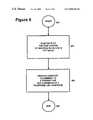
- FIG. 5is a flow chart of a method of optimizing a communication device coupled to a telephone network.
- FIG. 1is a block diagram of a transmitter and receiver coupled to a telephone network, such as Plain Old Telephone Service (POTS) network of a PSTN.
- a transmitter 100is coupled to a Customer Premise Equipment/Telephone Company (CPE/TELCO) interface 102 , such as a wall jack (e.g., an RJ-11 jack).
- CPE/TELCOCustomer Premise Equipment/Telephone Company
- the interface 102generally represents the boundary between the customer and the TELCO.
- Various CPEsare connected to a TELCO central office switch (CO) (not shown).
- the COis then coupled to a telephone network 104 .
- a receiving endis also coupled to the telephone network 104 by its corresponding central office (not shown).
- An interface representing the boundary of the customer premise and TELCOis represented by an interface 106 which couples the CO and a CPE receiver 108 .
- the CPEtypically include communication devices, such as a modem or a telephone.
- the CPEtypically adheres to interface standards.
- the interface standardstypically provide physical size and electrical loading requirements necessary for the CPE to operate at a defined quality of service. Without the standards, it is possible that a customer premise equipment may not function when coupled to the telephone network, nor perform at optimal levels.
- Telephone lines. 110 , 112couple the CPE/TELCO interfaces 102 , 106 with the telephone network 104 .
- the telephone lines 110 , 112are generally referred to as a local loop.
- the telephone lines 110 , 112include tip and ring conductors which have inherent line impedances.
- the TELCOprovides a DC potential of approximately 48 volts across the tip and ring conductors.
- POTSrefers to type of service of the PSTN. Access services, such as placing and receiving calls are generally defined by the EIA/TIA standard.
- the CPE 100 , 108needs to access the PSTN, the CPE 100 , 108 goes to an “off-hook” state.
- FIG. 2is a block diagram of a telephone network using a telephone interface.
- a CPE 200such as a modem, is coupled to a telephone interface 202 .
- the telephone interface 202can be incorporated into the CPE 200 or the telephone interface 202 can be a stand-alone device coupled to the CPE 200 .
- An CPE/TELCO interface 102illustrates the boundary between the customer premises and the telephone company.
- the CPE/TELCO interface 102is coupled to a telephone network 104 , such as a Plain Old Telephone Service (POTS) network, an x Digital Subscriber Line (xDSL) network, or an Integrated Services Digital Network (ISDN).
- POTSPlain Old Telephone Service
- xDSLx Digital Subscriber Line
- ISDNIntegrated Services Digital Network
- the CPE 200is coupled to the CPE/TELCO interface 102 , and typically adheres to a variety of standards, including an electrical interface standard.
- an electrical interface standardFor example, in the United States, the interface standard is EIA/TIA standard.
- the EIA/TIA standardprovides electrical requirements for accessing the PSTN. For example, the EIA/TIA standard specifies that it is desirable that a minimum of 40 seconds be allowed at the completion of dialing, before a call is abandoned and retried. Other requirements include a communication device's impedance when the device is on-hook or off-hook. Generally, the PTSN's impedance varies depending on a variety of conditions, such as the CPE/TELCO interface's 102 distance from a Central Office (not shown).
- FIG. 3is a block diagram of a telephone interface.
- the universal telephone interface 202is typically part of an Analog Front End (AFE) of the CPE 200 .
- the telephone interface 202is coupled to the CPE/TELCO interface (not shown) generally by tip and ring conductors. Although the tip and the ring conductors are shown in the figure, they can be used interchangeable that is, the conductor labeled “tip,” could be a “ring” conductor, and the conductor labeled “ring” could be a “tip” conductor.
- the telephone interface 202generally includes a driver 302 , a current source circuit 300 , and a hybrid receiver 304 .
- An INPUT and an OUTPUTare typically coupled to a Coder/Decoder (CODEC) (not shown).
- the OUTPUT of the CODECis generally provided to the input of the driver 302 .
- the outputs of the driver 302are coupled to the current source circuit 300 and the hybrid receiver 304 .
- part of the output of the driver 302is provided to the telephone network 104 via tip and ring lines.
- the hybrid receiver 304generally provides a rejection of the transmit signals from the driver 302 , while providing receive signals from the telephone network 104 to the INPUT of the CODEC.
- the current source circuit 300generally provides a constant current for interfacing the CPE 200 when the telephone network 104 .
- the current source circuit 300can be adjusted automatically depending upon the loading requirements of the telephone network 104 .
- the impedance of the telephone network 104typically varies depending upon conditions of the telephone network 104 , such the CPE/TELCO's 102 distance to the CO (not shown).
- FIG. 4is a circuit diagram of a constant current source circuit of a telephone interface.
- the current source circuit 300is coupled to a transformer TI and a RING and a TIP conductor of the CPE/TELCO I/F 102 .
- An on-hook relay 400is coupled to the ring conductor of the constant current circuit 300 .
- the off-hook relay 400closes when the CPE 200 is in a off-hook state and couples the CPE 200 with the telephone network 104 .
- the off-hook relay 400is coupled to the RING conductor of the current circuit 300 .
- the off-hook relay 400 locationis not critical, and can be coupled to the TIP conductor of the current source circuit 300 .
- a diode bridge B 1is coupled to the off-hook relay 400 and TIP conductor.
- the diode bridge B 1rectifies the line voltage and provides the appropriate voltage polarity to voltage points V 1 and V 2 , should the TIP and RING conductors be reversed.
- the voltage point V 1should always be greater than or equal to the voltage at the voltage point V 2 .
- Data transmitted over the telephone network 104is typically represented by the AC component of an electrical signal.
- a capacitor Cldecouples an DC component of the signal and provides the AC component to the transformer T 1 .
- the transformer T 1is coupled to the driver and hybrid receiver (not shown) and typically provides electrical isolation between the CPE 200 and the telephone network 104 .
- a driver 402is coupled to a 6.2 volt reference diode via resistors RS and R 6 , which divide the 6.2 volts and provide a 0.86 volt reference to the non inverting input of the driver 402 (when the resistors R 5 and R 6 are 62 k ⁇ and 10K ⁇ respectively).
- the driver 402drives its output so that its inverting input is at that same voltage of 0.86 volts by driving a transistor Q 1 .
- the voltage across a resistor R 7is held constant at that 0.86 volts, and when the resistor R 7 is selected at 27 ⁇ , the current through the resistor R 7 is constant at approximated 30 mA, which is drawn from the TIP and RING conductors via the bridge B 1 .
- a constant DC biasing currentis drawn.
- a variety of other constant current sourcescould be substituted for sinking current.
- capacitor C 3used with the driver 402 to reduce high frequency response of the system. This allows the constant current source to operate from DC to low frequency AC (direct current or low. frequency AC with no voice or other data) to establish the constant current source, while still allowing the higher frequency voice or modem or other data to pass through the capacitor C 1 to the transformer T 1 .
- FIG. 5is flow chart of a method of providing a constant DC current source.
- the methodstarts at step 500 .
- the DC voltage across the TIP and RING conductors of the CPE 200fluctuate at step 502 .
- a constant DC currentis provided to the tip and ring conductor of a transmitter and a receiver of a telephone interface at step 504 .
- the methodends at step 506 .
- the CPE 200can typically be used with various telephone networks, where loads may fluctuate. Since the CPE 200 can be dynamically adjusted, the CPE 200 can be coupled to any telephone network 104 without suffering from signal distortion due to DC biasing currents.
Landscapes
- Engineering & Computer Science (AREA)
- Signal Processing (AREA)
- Telephonic Communication Services (AREA)
Abstract
Description
Claims (36)
Priority Applications (1)
| Application Number | Priority Date | Filing Date | Title |
|---|---|---|---|
| US09/397,414US6819761B1 (en) | 1999-09-16 | 1999-09-16 | Programmable constant current “off hook” circuit |
Applications Claiming Priority (1)
| Application Number | Priority Date | Filing Date | Title |
|---|---|---|---|
| US09/397,414US6819761B1 (en) | 1999-09-16 | 1999-09-16 | Programmable constant current “off hook” circuit |
Publications (1)
| Publication Number | Publication Date |
|---|---|
| US6819761B1true US6819761B1 (en) | 2004-11-16 |
Family
ID=33415786
Family Applications (1)
| Application Number | Title | Priority Date | Filing Date |
|---|---|---|---|
| US09/397,414Expired - Fee RelatedUS6819761B1 (en) | 1999-09-16 | 1999-09-16 | Programmable constant current “off hook” circuit |
Country Status (1)
| Country | Link |
|---|---|
| US (1) | US6819761B1 (en) |
Cited By (2)
| Publication number | Priority date | Publication date | Assignee | Title |
|---|---|---|---|---|
| US20050012402A1 (en)* | 2003-07-16 | 2005-01-20 | Dell Products L.P. | Power source input distribution to a power supply |
| CN108566495A (en)* | 2018-05-31 | 2018-09-21 | 杭州小犇科技有限公司 | A kind of subscriber's line circuit for supporting to generally call function |
Citations (25)
| Publication number | Priority date | Publication date | Assignee | Title |
|---|---|---|---|---|
| US4056691A (en)* | 1977-01-05 | 1977-11-01 | Bell Telephone Laboratories, Incorporated | Telephone subscriber line circuit |
| US4203006A (en) | 1978-04-20 | 1980-05-13 | Prentice Corporation | Direct access coupler |
| US4281219A (en) | 1978-02-01 | 1981-07-28 | Mitel Corporation | Telephone line circuit |
| US4679232A (en)* | 1985-08-02 | 1987-07-07 | American Telephone And Telegraph Company, At&T Bell Laboratories | Method and apparatus for providing a ground reference for telephone customer special circuits powered from a floating battery feed |
| US4686700A (en) | 1986-10-24 | 1987-08-11 | Keptel, Inc. | Telephone off-hook detector circuit |
| US4704670A (en)* | 1986-12-31 | 1987-11-03 | American Telephone & Telegraph Company, At&T Bell Laboratories | Power supply with regulated output voltage |
| US4803721A (en)* | 1986-12-24 | 1989-02-07 | Mitel Corp. | DC control circuit |
| US4803719A (en)* | 1987-06-04 | 1989-02-07 | Ulrich Thomas J | Method for powering telephone apparatus and telephone apparatus powered directly from the telephone line without external power |
| US4827503A (en)* | 1986-10-20 | 1989-05-02 | Fujitsu Limited | Integrated ringing circuit and a ring trip circuit for the same |
| US4958371A (en)* | 1988-04-19 | 1990-09-18 | Control Data Corporation | Method and apparatus for determining when a telephone handset is off-hook |
| US5369687A (en) | 1992-12-17 | 1994-11-29 | Practical Peripherals, Inc. | Apparatus for electrically isolating a telephone line from a data device |
| US5428730A (en) | 1992-12-15 | 1995-06-27 | International Business Machines Corporation | Multimedia system having software mechanism providing standardized interfaces and controls for the operation of multimedia devices |
| US5454031A (en)* | 1993-06-04 | 1995-09-26 | M & Fc Holding Company, Inc. | Dial inbound meter interface unit which derives its power from a telephone line |
| US5625679A (en) | 1996-04-23 | 1997-04-29 | Gutzmer Enterprises, Ltd. | Telephone handset interface for alternating voice-data (AVD) modem |
| US5680323A (en) | 1995-06-23 | 1997-10-21 | Canon Information Systems, Inc. | Multimedia player |
| US5737706A (en)* | 1995-08-03 | 1998-04-07 | Bell Atlantic Network Services, Inc. | Power system supporting CDPD operation |
| US5790653A (en) | 1995-01-06 | 1998-08-04 | Voicewaves, Inc. | Line-powered detection of call progress tones |
| US5790656A (en)* | 1995-09-29 | 1998-08-04 | Rockwell International Corporation | Data access arrangement with telephone interface |
| US5796789A (en) | 1997-01-06 | 1998-08-18 | Omega Electronics Inc. | Alerting device for telephones |
| US5881129A (en)* | 1996-05-10 | 1999-03-09 | Chen; Robert Kuo-Wei | Self-monitoring line interface circuit |
| US6121263A (en)* | 1993-09-22 | 2000-09-19 | The Board Of Trustees Of The Leland Stanford Junior University | Method of tumor treatment |
| US6275583B1 (en)* | 1998-03-25 | 2001-08-14 | International Business Machines Corporation | Circuits and methods for improved network interface circuit protection |
| US6292544B1 (en)* | 1998-04-06 | 2001-09-18 | Ag Communcation Systems Corporation | Message waiting indicator in a computer integrated telephony system |
| US6377681B1 (en)* | 1998-04-01 | 2002-04-23 | National Semiconductor Corporation | Signal line driving circuit with self-controlled power dissipation |
| US6538510B1 (en)* | 1999-08-16 | 2003-03-25 | Globespanvirata, Inc. | High efficiency, current sink only line driver |
- 1999
- 1999-09-16USUS09/397,414patent/US6819761B1/ennot_activeExpired - Fee Related
Patent Citations (25)
| Publication number | Priority date | Publication date | Assignee | Title |
|---|---|---|---|---|
| US4056691A (en)* | 1977-01-05 | 1977-11-01 | Bell Telephone Laboratories, Incorporated | Telephone subscriber line circuit |
| US4281219A (en) | 1978-02-01 | 1981-07-28 | Mitel Corporation | Telephone line circuit |
| US4203006A (en) | 1978-04-20 | 1980-05-13 | Prentice Corporation | Direct access coupler |
| US4679232A (en)* | 1985-08-02 | 1987-07-07 | American Telephone And Telegraph Company, At&T Bell Laboratories | Method and apparatus for providing a ground reference for telephone customer special circuits powered from a floating battery feed |
| US4827503A (en)* | 1986-10-20 | 1989-05-02 | Fujitsu Limited | Integrated ringing circuit and a ring trip circuit for the same |
| US4686700A (en) | 1986-10-24 | 1987-08-11 | Keptel, Inc. | Telephone off-hook detector circuit |
| US4803721A (en)* | 1986-12-24 | 1989-02-07 | Mitel Corp. | DC control circuit |
| US4704670A (en)* | 1986-12-31 | 1987-11-03 | American Telephone & Telegraph Company, At&T Bell Laboratories | Power supply with regulated output voltage |
| US4803719A (en)* | 1987-06-04 | 1989-02-07 | Ulrich Thomas J | Method for powering telephone apparatus and telephone apparatus powered directly from the telephone line without external power |
| US4958371A (en)* | 1988-04-19 | 1990-09-18 | Control Data Corporation | Method and apparatus for determining when a telephone handset is off-hook |
| US5428730A (en) | 1992-12-15 | 1995-06-27 | International Business Machines Corporation | Multimedia system having software mechanism providing standardized interfaces and controls for the operation of multimedia devices |
| US5369687A (en) | 1992-12-17 | 1994-11-29 | Practical Peripherals, Inc. | Apparatus for electrically isolating a telephone line from a data device |
| US5454031A (en)* | 1993-06-04 | 1995-09-26 | M & Fc Holding Company, Inc. | Dial inbound meter interface unit which derives its power from a telephone line |
| US6121263A (en)* | 1993-09-22 | 2000-09-19 | The Board Of Trustees Of The Leland Stanford Junior University | Method of tumor treatment |
| US5790653A (en) | 1995-01-06 | 1998-08-04 | Voicewaves, Inc. | Line-powered detection of call progress tones |
| US5680323A (en) | 1995-06-23 | 1997-10-21 | Canon Information Systems, Inc. | Multimedia player |
| US5737706A (en)* | 1995-08-03 | 1998-04-07 | Bell Atlantic Network Services, Inc. | Power system supporting CDPD operation |
| US5790656A (en)* | 1995-09-29 | 1998-08-04 | Rockwell International Corporation | Data access arrangement with telephone interface |
| US5625679A (en) | 1996-04-23 | 1997-04-29 | Gutzmer Enterprises, Ltd. | Telephone handset interface for alternating voice-data (AVD) modem |
| US5881129A (en)* | 1996-05-10 | 1999-03-09 | Chen; Robert Kuo-Wei | Self-monitoring line interface circuit |
| US5796789A (en) | 1997-01-06 | 1998-08-18 | Omega Electronics Inc. | Alerting device for telephones |
| US6275583B1 (en)* | 1998-03-25 | 2001-08-14 | International Business Machines Corporation | Circuits and methods for improved network interface circuit protection |
| US6377681B1 (en)* | 1998-04-01 | 2002-04-23 | National Semiconductor Corporation | Signal line driving circuit with self-controlled power dissipation |
| US6292544B1 (en)* | 1998-04-06 | 2001-09-18 | Ag Communcation Systems Corporation | Message waiting indicator in a computer integrated telephony system |
| US6538510B1 (en)* | 1999-08-16 | 2003-03-25 | Globespanvirata, Inc. | High efficiency, current sink only line driver |
Non-Patent Citations (1)
| Title |
|---|
| EIA/TIA-496-A Interface between Data Circuit-Terminating Equipment (DCE) and the Public Switched Telephone Network (PSTN), Electronic Industries Association, (Sep. 28, 1999). |
Cited By (4)
| Publication number | Priority date | Publication date | Assignee | Title |
|---|---|---|---|---|
| US20050012402A1 (en)* | 2003-07-16 | 2005-01-20 | Dell Products L.P. | Power source input distribution to a power supply |
| US7215044B2 (en)* | 2003-07-16 | 2007-05-08 | Dell Products L.P. | Power distribution board having connectors with AC and DC power distribution capabilities |
| CN108566495A (en)* | 2018-05-31 | 2018-09-21 | 杭州小犇科技有限公司 | A kind of subscriber's line circuit for supporting to generally call function |
| CN108566495B (en)* | 2018-05-31 | 2023-10-10 | 杭州小犇科技有限公司 | User circuit supporting full calling function |
Similar Documents
| Publication | Publication Date | Title |
|---|---|---|
| JP2850126B2 (en) | Line interface circuit | |
| US20070201687A1 (en) | Subscriber Line Interface Circuitry | |
| AU1878392A (en) | Call control method in a digital transmission system | |
| US5600715A (en) | Integrated loop current detector apparatus for a PSTN modem | |
| KR100626991B1 (en) | A system and method for allocating overhead voltage in the transmission of POTS and XDSL signals | |
| KR100446585B1 (en) | A method and system for scaleable near-end speech cancellation for tip and ring tone signal detectors | |
| JP2001508628A (en) | Subscriber line interface circuit (SLIC) simulator | |
| US6819761B1 (en) | Programmable constant current “off hook” circuit | |
| US6359972B1 (en) | Line in use detection | |
| US6137189A (en) | Line circuit apparatus for supplying power to a telephone set in telecommunication systems | |
| US6671373B1 (en) | Method and apparatus for DC feed control | |
| JPH04233891A (en) | Interface device for button telephone set | |
| US6757380B2 (en) | Impedance blocking filter circuit for digital subscriber line communication systems | |
| JP2847841B2 (en) | Polarity inversion circuit | |
| KR20000037675A (en) | Internet phone splitter | |
| US6700974B1 (en) | Switching power supply for generating a ringing voltage | |
| US6934382B1 (en) | Method for recognizing an off-hook condition on a single subscriber line with two terminal devices | |
| KR100540247B1 (en) | Echo cancellation device for wireless subscriber network terminal and landline | |
| US6480603B1 (en) | Device which reduces central office battery current during modem connections | |
| AU6999698A (en) | Digital signal processor-based telephone test set | |
| WO1997045996A2 (en) | An adjunct arrangement for a telecommunication device | |
| KR100289580B1 (en) | Subscriber Board Simulator for Line Test | |
| EP1014657A1 (en) | Loop telephone line assembly and methods | |
| EP0089350A1 (en) | Electronic terminator circuit | |
| JPH0662168A (en) | Facsimile equipment |
Legal Events
| Date | Code | Title | Description |
|---|---|---|---|
| AS | Assignment | Owner name:CREDIT SUISSE FIRST BOSTON, NEW YORK Free format text:SECURITY INTEREST;ASSIGNOR:CONEXANT SYSTEMS, INC.;REEL/FRAME:010450/0899 Effective date:19981221 | |
| AS | Assignment | Owner name:CONEXANT SYSTEMS, INC., CALIFORNIA Free format text:ASSIGNMENT OF ASSIGNORS INTEREST;ASSIGNOR:WILLIAMS, H. ROSS;REEL/FRAME:010682/0446 Effective date:19991207 | |
| AS | Assignment | Owner name:CONEXANT SYSTEMS, INC., CALIFORNIA Free format text:RELEASE OF SECURITY INTEREST;ASSIGNOR:CREDIT SUISSE FIRST BOSTON;REEL/FRAME:012252/0865 Effective date:20011018 Owner name:BROOKTREE CORPORATION, CALIFORNIA Free format text:RELEASE OF SECURITY INTEREST;ASSIGNOR:CREDIT SUISSE FIRST BOSTON;REEL/FRAME:012252/0865 Effective date:20011018 Owner name:BROOKTREE WORLDWIDE SALES CORPORATION, CALIFORNIA Free format text:RELEASE OF SECURITY INTEREST;ASSIGNOR:CREDIT SUISSE FIRST BOSTON;REEL/FRAME:012252/0865 Effective date:20011018 Owner name:CONEXANT SYSTEMS WORLDWIDE, INC., CALIFORNIA Free format text:RELEASE OF SECURITY INTEREST;ASSIGNOR:CREDIT SUISSE FIRST BOSTON;REEL/FRAME:012252/0865 Effective date:20011018 | |
| AS | Assignment | Owner name:SILICON LABORATORIES INC., TEXAS Free format text:ASSIGNMENT OF ASSIGNORS INTEREST;ASSIGNOR:PCTEL, INC.;REEL/FRAME:014675/0579 Effective date:20031017 | |
| FEPP | Fee payment procedure | Free format text:PAYOR NUMBER ASSIGNED (ORIGINAL EVENT CODE: ASPN); ENTITY STATUS OF PATENT OWNER: LARGE ENTITY | |
| FPAY | Fee payment | Year of fee payment:4 | |
| FPAY | Fee payment | Year of fee payment:8 | |
| REMI | Maintenance fee reminder mailed | ||
| LAPS | Lapse for failure to pay maintenance fees | ||
| STCH | Information on status: patent discontinuation | Free format text:PATENT EXPIRED DUE TO NONPAYMENT OF MAINTENANCE FEES UNDER 37 CFR 1.362 | |
| FP | Lapsed due to failure to pay maintenance fee | Effective date:20161116 |