US6819362B2 - Disposition device for auto-detecting the holding condition of a digital camera - Google Patents
Disposition device for auto-detecting the holding condition of a digital cameraDownload PDFInfo
- Publication number
- US6819362B2 US6819362B2US09/790,767US79076701AUS6819362B2US 6819362 B2US6819362 B2US 6819362B2US 79076701 AUS79076701 AUS 79076701AUS 6819362 B2US6819362 B2US 6819362B2
- Authority
- US
- United States
- Prior art keywords
- digital camera
- disposition device
- cavity
- conductive
- holding condition
- Prior art date
- Legal status (The legal status is an assumption and is not a legal conclusion. Google has not performed a legal analysis and makes no representation as to the accuracy of the status listed.)
- Expired - Fee Related, expires
Links
Images


Classifications
- G—PHYSICS
- G03—PHOTOGRAPHY; CINEMATOGRAPHY; ANALOGOUS TECHNIQUES USING WAVES OTHER THAN OPTICAL WAVES; ELECTROGRAPHY; HOLOGRAPHY
- G03B—APPARATUS OR ARRANGEMENTS FOR TAKING PHOTOGRAPHS OR FOR PROJECTING OR VIEWING THEM; APPARATUS OR ARRANGEMENTS EMPLOYING ANALOGOUS TECHNIQUES USING WAVES OTHER THAN OPTICAL WAVES; ACCESSORIES THEREFOR
- G03B17/00—Details of cameras or camera bodies; Accessories therefor
- G03B17/56—Accessories
Definitions
- the inventionrelates to a disposition device for auto-detecting the holding condition of a digital camera.
- the inventionrelates to a disposition device, which automatically detects a digital camera whether it is held upright or horizontally.
- the charge-coupled device (CCD) or a complementary metal oxide semiconductor (CMOS) existing in the conventional video camerais introduced into the digital camera and shoots a picture of a subject, wherein the picture is stored in memory in order to show on the display later.
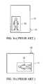
- the digital camerais held upright to shoot a full-length picture of a subject.
- FIG. 1 bafter shooting a picture of the subject, photographer commonly rotates the digital camera to a horizontal condition, and the picture displayed on the liquid crystal display of the digital camera is parallel to the ground. If user wants to view a picture meeting the vision via the viewfinder, the user can only rotate the digital camera to the upright condition or utilize built-in software to convert the picture into an upright image. However, whether the digital camera is rotated by a user or by converting the image by utilizing the built-in software, it is inconvenient.
- An object of this inventionis to solve the above-mentioned problems of the prior art by providing a disposition device for auto-detecting the holding condition of a digital camera. Firstly, when a digital camera shoots a picture of a subject, the disposition device detects the holding condition of the digital camera, such as an upright condition or a horizontal condition. Then, the disposition device sends a signal to the digital camera circuit. According to the signal, the digital camera circuit automatically executes the built-in software to convert the picture into an appropriate image meeting the vision via the viewfinder.
- a second object of this inventionis to provide a digital camera with a disposition device for automatically converting a picture to an appropriate image meeting the vision via the viewfinder, wherein the disposition device can send out an electronic signal representing the holding condition of the digital camera when shooting a picture of a subject. Therefore, while displaying the images by a display, a user can view an image meeting the appropriate vision via the viewfinder at that time.
- the inventionprovides a disposition device for auto-detecting the holding condition of a digital camera, comprising: an insulating envelope having a cavity which is formed by an insulating bottom and side wall, a conductive plate for covering the cavity of the insulating envelope, a plurality of conductive pads selectively located on the insulated bottom, and a movable sensor moving in the cavity according to the influence of gravity, wherein the movable sensor touching one of the conductive pads and the conductive plate represents the holding condition of the digital camera.
- FIG. 1 aschematically shows a conventional digital camera shooting a picture of a subject in an upright condition
- FIG. 1 bschematically shows the display direction of a picture, which is taken in the upright position by a conventional digital camera
- FIG. 2 ais a schematic cross-sectional view of a disposition device of the invention
- FIG. 2 bis an exploded diagram showing a disposition device of the invention
- FIGS. 3 a to 3 crespectively show a digital camera capturing an image of an object in different conditions.
- FIG. 4schematically shows a digital camera circuit of the invention.
- FIGS. 2 a and 2 brespectively show a cross-sectional view and an exploded view of a disposition device of the invention.
- the disposition devicecomprises: a conductive plate A, a movable sensor B, such as a conductive ball, an insulating envelope C, and a plurality of conductive pads D.
- the disposition deviceis a triangular structure, and has three concave regions 20 a , 20 b , and 20 c for positioning the conductive ball B therein. Two of the concave regions 20 a and 20 b are symmetrically located at two corners of the disposition device. As shown in FIG.
- the conductive plate Aconnects with a power source 4 , so that the disposition device can send an electronic signal to a digital camera circuit.
- the insulating envelope Chas a cavity which is formed by an insulating bottom and side wall, wherein the cavity is divided into three concave regions. Three conductive pads D are respectively located on the bottom surface.
- the movable sensor Bsuch as a conductive ball B, rolls in the cavity of the insulating envelope C.
- the conductive ball Bwould be selectively located in one of the concave regions by the influence of gravity.
- the conductive ball Bis located in one of the concave regions, one of the conductive pads locating on the insulating bottom touches the conductive ball B. Therefore, a current supplied from the power source will pass through the conductive plate A, the conductive ball B, and the conductive pad D touching the conductive ball B, and then the current as a signal sends out and represents the holding condition of the digital camera.
- FIGS. 3 a to 3 crespectively show a digital camera shooting a picture of a subject in different holding conditions.
- a digital camera 30 of the inventioncomprises a housing 32 , a button 34 , a liquid crystal display 36 and a disposition device 38 .
- the disposition device 38 of the inventioncan be installed at any location inside the digital camera.
- the conductive ball Bis located at the concave region 20 c .
- 3 a and 3 cshow another condition of the digital camera 30 which is also moved from the horizontal position to an upright position, and the conductive ball B is located at the concave region 20 b .
- the power source 4also provides the disposition device 38 with a current as a signal that is conducted to a corresponding I/O port 5 b on the digital camera circuit 5 by the loop 2 . Therefore, the digital camera circuit 5 receiving the electronic signal through the loop 2 represents that the digital camera 30 is rotated 90 degrees clockwise and held upright.
- the disposition deviceautomatically provides every picture with a notation that depicts whether the digital camera is held in the upright direction or the horizontal direction.
- the digital camera circuitautomatically executes the built-in software to convert the pictures into images meeting the visions via the viewfinder without user's operation. Therefore, the display, for example a LCD on the digital camera, a desktop monitor, a television, can show the images meeting the visions via the viewfinder.
Landscapes
- Physics & Mathematics (AREA)
- General Physics & Mathematics (AREA)
- Studio Devices (AREA)
- Viewfinders (AREA)
- Cameras In General (AREA)
Abstract
Description
Claims (11)
Applications Claiming Priority (3)
| Application Number | Priority Date | Filing Date | Title |
|---|---|---|---|
| TW089119732ATW521521B (en) | 2000-09-25 | 2000-09-25 | Positioning device for automatically correcting the image display direction |
| TW89119732 | 2000-09-25 | ||
| TW89119732A | 2000-09-25 |
Publications (2)
| Publication Number | Publication Date |
|---|---|
| US20020036703A1 US20020036703A1 (en) | 2002-03-28 |
| US6819362B2true US6819362B2 (en) | 2004-11-16 |
Family
ID=21661305
Family Applications (1)
| Application Number | Title | Priority Date | Filing Date |
|---|---|---|---|
| US09/790,767Expired - Fee RelatedUS6819362B2 (en) | 2000-09-25 | 2001-02-21 | Disposition device for auto-detecting the holding condition of a digital camera |
Country Status (3)
| Country | Link |
|---|---|
| US (1) | US6819362B2 (en) |
| JP (1) | JP2002112107A (en) |
| TW (1) | TW521521B (en) |
Cited By (10)
| Publication number | Priority date | Publication date | Assignee | Title |
|---|---|---|---|---|
| US20040004667A1 (en)* | 2001-08-15 | 2004-01-08 | Masayoshi Morikawa | Image recording/reproducing device |
| US20040185878A1 (en)* | 2003-01-30 | 2004-09-23 | Jung-Oh Woo | Device and method for displaying pictures in wireless mobile terminal |
| US20050074170A1 (en)* | 2003-10-01 | 2005-04-07 | Debrito Daniel N. | Method and apparatus for conveying image attributes |
| US20050093891A1 (en)* | 2003-11-04 | 2005-05-05 | Pixel Instruments Corporation | Image orientation apparatus and method |
| US20050195308A1 (en)* | 2004-03-02 | 2005-09-08 | Fuji Photo Film Co., Ltd. | Image pick-up system |
| US20060103734A1 (en)* | 2004-11-16 | 2006-05-18 | Samsung Techwin Co., Ltd. | Apparatus and method for rotating image in digital camera |
| US20070047943A1 (en)* | 2005-09-01 | 2007-03-01 | Samsung Electronics Co., Ltd. | Image processing method and apparatus and information storage medium storing image information |
| US20080225156A1 (en)* | 2007-03-14 | 2008-09-18 | Samsung Techwin Co., Ltd. | Digital image processing apparatus with rotating display device |
| US20100149377A1 (en)* | 2008-12-12 | 2010-06-17 | Koichi Shintani | Imaging apparatus |
| US20180247615A1 (en)* | 2017-02-28 | 2018-08-30 | Fu Tai Hua Industry (Shenzhen) Co., Ltd. | Image controlling apparatus and digital photo frame using the same |
Families Citing this family (3)
| Publication number | Priority date | Publication date | Assignee | Title |
|---|---|---|---|---|
| TWI476740B (en)* | 2008-12-22 | 2015-03-11 | Inventec Appliances Corp | An electronic device capable of automatically adjusting the direction of an image on a display and a method for the adjusting |
| JP2011053330A (en)* | 2009-08-31 | 2011-03-17 | Canon Inc | Electronic apparatus |
| KR20110061063A (en)* | 2009-12-01 | 2011-06-09 | 삼성전자주식회사 | Method and device for taking images of mobile terminal |
Citations (14)
| Publication number | Priority date | Publication date | Assignee | Title |
|---|---|---|---|---|
| US4364650A (en)* | 1979-10-05 | 1982-12-21 | Fuji Photo Film Co., Ltd. | Exposure control method and device |
| US5122827A (en)* | 1987-07-07 | 1992-06-16 | Nikon Corporation | Camera provided with an attitude detecting device |
| US5144358A (en)* | 1988-03-02 | 1992-09-01 | Nikon Corporation | Automatic focusing camera |
| JPH0668756A (en)* | 1991-05-21 | 1994-03-11 | Minolta Camera Co Ltd | Attitude detecting sensor |
| JPH07190761A (en)* | 1993-12-27 | 1995-07-28 | Nikon Corp | Tilt sensor |
| JPH08114830A (en)* | 1994-10-13 | 1996-05-07 | Nikon Corp | Exposure calculation control device |
| US5710947A (en)* | 1995-04-04 | 1998-01-20 | Eastman Kodak Company | Pressure sensor control for electrically responsive camera feature |
| US5764291A (en)* | 1994-09-30 | 1998-06-09 | Apple Computer, Inc. | Apparatus and method for orientation-dependent camera exposure and focus setting optimization |
| US5900909A (en)* | 1995-04-13 | 1999-05-04 | Eastman Kodak Company | Electronic still camera having automatic orientation sensing and image correction |
| JPH11162306A (en)* | 1997-09-16 | 1999-06-18 | Alps Electric Co Ltd | Inclination sensor |
| US6104307A (en)* | 1998-09-17 | 2000-08-15 | Hanratty; Peter | Package-mounted sensor |
| US6148149A (en)* | 1998-05-26 | 2000-11-14 | Microsoft Corporation | Automatic image rotation in digital cameras |
| US20010007469A1 (en)* | 2000-01-07 | 2001-07-12 | Asahi Kogaku Kogyo Kabushiki Kaisha | Digital camera having a position sensor |
| US20040075571A1 (en)* | 2000-01-06 | 2004-04-22 | Fong Peter Sui Lun | Level/position sensor and related electronic circuitry for interactive toy |
- 2000
- 2000-09-25TWTW089119732Apatent/TW521521B/ennot_activeIP Right Cessation
- 2001
- 2001-02-21USUS09/790,767patent/US6819362B2/ennot_activeExpired - Fee Related
- 2001-03-23JPJP2001084502Apatent/JP2002112107A/enactivePending
Patent Citations (14)
| Publication number | Priority date | Publication date | Assignee | Title |
|---|---|---|---|---|
| US4364650A (en)* | 1979-10-05 | 1982-12-21 | Fuji Photo Film Co., Ltd. | Exposure control method and device |
| US5122827A (en)* | 1987-07-07 | 1992-06-16 | Nikon Corporation | Camera provided with an attitude detecting device |
| US5144358A (en)* | 1988-03-02 | 1992-09-01 | Nikon Corporation | Automatic focusing camera |
| JPH0668756A (en)* | 1991-05-21 | 1994-03-11 | Minolta Camera Co Ltd | Attitude detecting sensor |
| JPH07190761A (en)* | 1993-12-27 | 1995-07-28 | Nikon Corp | Tilt sensor |
| US5764291A (en)* | 1994-09-30 | 1998-06-09 | Apple Computer, Inc. | Apparatus and method for orientation-dependent camera exposure and focus setting optimization |
| JPH08114830A (en)* | 1994-10-13 | 1996-05-07 | Nikon Corp | Exposure calculation control device |
| US5710947A (en)* | 1995-04-04 | 1998-01-20 | Eastman Kodak Company | Pressure sensor control for electrically responsive camera feature |
| US5900909A (en)* | 1995-04-13 | 1999-05-04 | Eastman Kodak Company | Electronic still camera having automatic orientation sensing and image correction |
| JPH11162306A (en)* | 1997-09-16 | 1999-06-18 | Alps Electric Co Ltd | Inclination sensor |
| US6148149A (en)* | 1998-05-26 | 2000-11-14 | Microsoft Corporation | Automatic image rotation in digital cameras |
| US6104307A (en)* | 1998-09-17 | 2000-08-15 | Hanratty; Peter | Package-mounted sensor |
| US20040075571A1 (en)* | 2000-01-06 | 2004-04-22 | Fong Peter Sui Lun | Level/position sensor and related electronic circuitry for interactive toy |
| US20010007469A1 (en)* | 2000-01-07 | 2001-07-12 | Asahi Kogaku Kogyo Kabushiki Kaisha | Digital camera having a position sensor |
Cited By (18)
| Publication number | Priority date | Publication date | Assignee | Title |
|---|---|---|---|---|
| US20040004667A1 (en)* | 2001-08-15 | 2004-01-08 | Masayoshi Morikawa | Image recording/reproducing device |
| US7551220B2 (en)* | 2001-08-15 | 2009-06-23 | Sony Corporation | Image recording/reproducing device with dual-operated switch depending upon orientation of the device |
| US20040185878A1 (en)* | 2003-01-30 | 2004-09-23 | Jung-Oh Woo | Device and method for displaying pictures in wireless mobile terminal |
| US20050074170A1 (en)* | 2003-10-01 | 2005-04-07 | Debrito Daniel N. | Method and apparatus for conveying image attributes |
| US7221811B2 (en)* | 2003-10-01 | 2007-05-22 | Hewlett-Packard Development Company, L.P. | Method and apparatus for conveying image attributes |
| US20050093891A1 (en)* | 2003-11-04 | 2005-05-05 | Pixel Instruments Corporation | Image orientation apparatus and method |
| US20050195308A1 (en)* | 2004-03-02 | 2005-09-08 | Fuji Photo Film Co., Ltd. | Image pick-up system |
| US7471328B2 (en)* | 2004-11-16 | 2008-12-30 | Samsung Techwin Co., Ltd. | Apparatus and method for rotating image in digital camera |
| US20060103734A1 (en)* | 2004-11-16 | 2006-05-18 | Samsung Techwin Co., Ltd. | Apparatus and method for rotating image in digital camera |
| US8098981B2 (en)* | 2005-09-01 | 2012-01-17 | Samsung Electronics Co., Ltd. | Image processing method and apparatus and information storage medium storing image information |
| US20070047943A1 (en)* | 2005-09-01 | 2007-03-01 | Samsung Electronics Co., Ltd. | Image processing method and apparatus and information storage medium storing image information |
| US8422872B2 (en) | 2005-09-01 | 2013-04-16 | Samsung Electronics Co., Ltd. | Image processing method and apparatus and information storage medium storing image information |
| US8639102B2 (en) | 2005-09-01 | 2014-01-28 | Samsung Electronics Co., Ltd. | Image processing method and apparatus and information storage medium storing image information |
| US20080225156A1 (en)* | 2007-03-14 | 2008-09-18 | Samsung Techwin Co., Ltd. | Digital image processing apparatus with rotating display device |
| US20100149377A1 (en)* | 2008-12-12 | 2010-06-17 | Koichi Shintani | Imaging apparatus |
| US8502878B2 (en)* | 2008-12-12 | 2013-08-06 | Olympus Imaging Corp. | Imaging apparatus having a changeable operating mode responsive to an inclined orientation |
| US20180247615A1 (en)* | 2017-02-28 | 2018-08-30 | Fu Tai Hua Industry (Shenzhen) Co., Ltd. | Image controlling apparatus and digital photo frame using the same |
| US10157596B2 (en)* | 2017-02-28 | 2018-12-18 | Fu Tai Hua Industry (Shenzhen) Co., Ltd. | Image controlling apparatus and digital photo frame using the same |
Also Published As
| Publication number | Publication date |
|---|---|
| TW521521B (en) | 2003-02-21 |
| US20020036703A1 (en) | 2002-03-28 |
| JP2002112107A (en) | 2002-04-12 |
Similar Documents
| Publication | Publication Date | Title |
|---|---|---|
| US11675250B2 (en) | Imaging apparatus with display and image display apparatus | |
| US6819362B2 (en) | Disposition device for auto-detecting the holding condition of a digital camera | |
| US7305771B2 (en) | Rotation sensor | |
| JPH08223492A (en) | Portable image pickup device or image pickup element thereof | |
| JP3282622B2 (en) | Electronic camera | |
| JP5680129B2 (en) | IMAGING DEVICE AND IMAGING DEVICE CONTROL METHOD | |
| JP2010166524A (en) | Imaging device | |
| US20050122414A1 (en) | Digital camera system and method for maximizing television viewing area | |
| CN1159672C (en) | Orientation device for automatically correcting image display direction | |
| JP2010141736A (en) | Image capturing apparatus | |
| JP5963890B2 (en) | IMAGING DEVICE, IMAGING DEVICE CONTROL METHOD, AND IMAGING DEVICE MODE SWITCHING PROGRAM | |
| JP2000350064A (en) | Imaging device |
Legal Events
| Date | Code | Title | Description |
|---|---|---|---|
| AS | Assignment | Owner name:ACER COMMUNICATIONS AND MULTIMEDIA INC., TAIWAN Free format text:ASSIGNMENT OF ASSIGNORS INTEREST;ASSIGNOR:HSU, YING-HAO;REEL/FRAME:011561/0353 Effective date:20010208 | |
| AS | Assignment | Owner name:BENQ CORPORATION, TAIWAN Free format text:CHANGE OF NAME;ASSIGNORS:ACER PERIPHERALS, INC.;ACER COMMUNICATIONS & MULTIMEDIA INC.;REEL/FRAME:012939/0847 Effective date:20020401 | |
| AS | Assignment | Owner name:BENQ CORPORATION, TAIWAN Free format text:CHANGE OF NAME;ASSIGNOR:ACER COMMUNICATIONS & MULTIMEDIA INC.;REEL/FRAME:015051/0449 Effective date:20011231 | |
| AS | Assignment | Owner name:QISDA CORPORATION, TAIWAN Free format text:CHANGE OF NAME;ASSIGNOR:BENQ CORPORATION;REEL/FRAME:020723/0081 Effective date:20070831 | |
| FPAY | Fee payment | Year of fee payment:4 | |
| FPAY | Fee payment | Year of fee payment:8 | |
| REMI | Maintenance fee reminder mailed | ||
| LAPS | Lapse for failure to pay maintenance fees | ||
| STCH | Information on status: patent discontinuation | Free format text:PATENT EXPIRED DUE TO NONPAYMENT OF MAINTENANCE FEES UNDER 37 CFR 1.362 | |
| FP | Expired due to failure to pay maintenance fee | Effective date:20161116 |