US6819098B2 - Utility power meter database - Google Patents
Utility power meter databaseDownload PDFInfo
- Publication number
- US6819098B2 US6819098B2US10/262,259US26225902AUS6819098B2US 6819098 B2US6819098 B2US 6819098B2US 26225902 AUS26225902 AUS 26225902AUS 6819098 B2US6819098 B2US 6819098B2
- Authority
- US
- United States
- Prior art keywords
- utility meter
- information
- accordance
- database
- meter
- Prior art date
- Legal status (The legal status is an assumption and is not a legal conclusion. Google has not performed a legal analysis and makes no representation as to the accuracy of the status listed.)
- Expired - Lifetime
Links
Images


Classifications
- G—PHYSICS
- G01—MEASURING; TESTING
- G01D—MEASURING NOT SPECIALLY ADAPTED FOR A SPECIFIC VARIABLE; ARRANGEMENTS FOR MEASURING TWO OR MORE VARIABLES NOT COVERED IN A SINGLE OTHER SUBCLASS; TARIFF METERING APPARATUS; MEASURING OR TESTING NOT OTHERWISE PROVIDED FOR
- G01D4/00—Tariff metering apparatus
- G01D4/002—Remote reading of utility meters
- G01D4/004—Remote reading of utility meters to a fixed location
- H—ELECTRICITY
- H04—ELECTRIC COMMUNICATION TECHNIQUE
- H04L—TRANSMISSION OF DIGITAL INFORMATION, e.g. TELEGRAPHIC COMMUNICATION
- H04L67/00—Network arrangements or protocols for supporting network services or applications
- H04L67/01—Protocols
- H04L67/02—Protocols based on web technology, e.g. hypertext transfer protocol [HTTP]
- H04L67/025—Protocols based on web technology, e.g. hypertext transfer protocol [HTTP] for remote control or remote monitoring of applications
- H—ELECTRICITY
- H04—ELECTRIC COMMUNICATION TECHNIQUE
- H04L—TRANSMISSION OF DIGITAL INFORMATION, e.g. TELEGRAPHIC COMMUNICATION
- H04L69/00—Network arrangements, protocols or services independent of the application payload and not provided for in the other groups of this subclass
- H04L69/30—Definitions, standards or architectural aspects of layered protocol stacks
- H04L69/32—Architecture of open systems interconnection [OSI] 7-layer type protocol stacks, e.g. the interfaces between the data link level and the physical level
- H04L69/322—Intralayer communication protocols among peer entities or protocol data unit [PDU] definitions
- H04L69/329—Intralayer communication protocols among peer entities or protocol data unit [PDU] definitions in the application layer [OSI layer 7]
- Y—GENERAL TAGGING OF NEW TECHNOLOGICAL DEVELOPMENTS; GENERAL TAGGING OF CROSS-SECTIONAL TECHNOLOGIES SPANNING OVER SEVERAL SECTIONS OF THE IPC; TECHNICAL SUBJECTS COVERED BY FORMER USPC CROSS-REFERENCE ART COLLECTIONS [XRACs] AND DIGESTS
- Y02—TECHNOLOGIES OR APPLICATIONS FOR MITIGATION OR ADAPTATION AGAINST CLIMATE CHANGE
- Y02B—CLIMATE CHANGE MITIGATION TECHNOLOGIES RELATED TO BUILDINGS, e.g. HOUSING, HOUSE APPLIANCES OR RELATED END-USER APPLICATIONS
- Y02B90/00—Enabling technologies or technologies with a potential or indirect contribution to GHG emissions mitigation
- Y02B90/20—Smart grids as enabling technology in buildings sector
- Y—GENERAL TAGGING OF NEW TECHNOLOGICAL DEVELOPMENTS; GENERAL TAGGING OF CROSS-SECTIONAL TECHNOLOGIES SPANNING OVER SEVERAL SECTIONS OF THE IPC; TECHNICAL SUBJECTS COVERED BY FORMER USPC CROSS-REFERENCE ART COLLECTIONS [XRACs] AND DIGESTS
- Y04—INFORMATION OR COMMUNICATION TECHNOLOGIES HAVING AN IMPACT ON OTHER TECHNOLOGY AREAS
- Y04S—SYSTEMS INTEGRATING TECHNOLOGIES RELATED TO POWER NETWORK OPERATION, COMMUNICATION OR INFORMATION TECHNOLOGIES FOR IMPROVING THE ELECTRICAL POWER GENERATION, TRANSMISSION, DISTRIBUTION, MANAGEMENT OR USAGE, i.e. SMART GRIDS
- Y04S20/00—Management or operation of end-user stationary applications or the last stages of power distribution; Controlling, monitoring or operating thereof
- Y04S20/30—Smart metering, e.g. specially adapted for remote reading
Definitions
- This inventionpertains to utility company meters and systems for metering electrical energy, in general, and to single phase residential type watt-hour meters and systems and methods for the measurement of electrical energy consumption for revenue metering and for other energy consumption applications, in particular.
- Utility company metersare of three general types, namely, electromechanical based meters, purely electronic component based meters, and hybrid electromechanical/electronic meters.
- the electromechanical and hybrid type metersare essentially an induction motor in which the moving element is a rotating disk. The speed of rotation of the disk is directly proportional to the voltage applied and the amount of current flowing through the motor. The phase displacement of the current, as well as the magnitude of the current, is automatically taken into account by the meter, i.e., the power factor influences the speed of rotation of the disk. The result is that the disk rotates with a speed proportional to true power.
- a registeris used to register the number of revolutions, and the gearing is arranged to be read directly in kilowatt-hours.
- the electric utility meters most commonly in useare of the electromechanical type.
- the metersare generally highly reliable, but do not lend themselves to remote or automated reading.
- Hybrid meterstypically utilize electronic circuitry in combination with the rotating disk to permit at least limited two-way communication to/from the meter.
- the two-way communicationis limited to reading the meter via a proprietary communications link that frequently is a limited range radio frequency link.
- the tariffsmay be time of use type tariffs, or may be changed from time to time or on predetermined dates to provide for various time of use type of rates.
- the present inventionprovides the next generation of time-sensitive advanced metering data collection and management solutions for utilities and energy service providers.
- the meter and system of the inventionprovide unmatched two-way, secure internet-based access to real-time usage information between data networks and control systems.
- the systemmeasures residential energy consumption and automatically communicates this information to a host computer.
- the host computercan then be accessed by the end utility customer or other authorized entities.
- This Internet or web based systemoffers two-way communication capability to support meter reconfiguration.
- the systemis comprised of two major elements, a hardware unit and database software.
- a utility meter databasein accordance with the principles of the invention comprises account identification information to identify a user account, a utility meter serial number for a utility meter for the user account, and utility meter configuration information for downloading to said utility meter.
- the databasefurther includes account consumption information obtained from said utility meter.
- the databaseis utilized for storage, configuration and analysis of energy usage data that is transmitted from the hardware unit.
- the databasemaintains the usage information in a summarized form and provides real time analysis of the data via open and secure API's (application protocol interfaces).
- the databasecan be accessed over the Internet to access and extract data files.
- the output format of the databasecan readily be configured to integrate to a utility company's computer system and database.
- a system in accordance with the principles of the inventionprovides timely access to time-sensitive usage data gives energy providers an edge in an increasingly competitive and rapidly transforming utility environment.
- Electric usage meters in accordance with the inventioncapture and transmit energy-use information in configurable time intervals directly to a data center via public networks.
- Each meter in accordance with the principles of the inventionincludes built-in measurement and state-of-the-art data communications systems that provide high-volume, real-time energy-use monitoring over the Internet to a server and database.
- the system of the present inventioneliminates the need to deploy costly, complex, and often high-maintenance private communications networks to capture periodic utility data.
- Standard Internet browser technology and encrypted messagingprovide secure, easy accessibility to metered data.
- the meters and systemprovide the ability to capture, analyze and consistently deliver accurate and timely electric-use consumption data is critical to the future growth of electricity providers everywhere.
- a system in accordance with the inventionutilizes a scalable architecture that permits power usage data to be calculated and stored incrementally for automatic transmission.
- power usage datais acquired from meters in 15-minute increments instead of the monthly or 30-day time frame presently used.
- utilitiescan better predict and manage electricity use.
- the system of the inventiongives great latitude to utilities to select a deployment strategy best suited to their unique needs. There is no implicit requirement for mass installation of geographic metering territories as with some systems. Thus, utilities with strategies for “surgical” implementation of AMR are easily accommodated.
- the methodincludes utilizing a public network for the communication link.
- the public networkcomprises a worldwide network of computers.
- the public network in the embodiment showncomprises the Internet and the communications link includes a telephone link.
- the telephone linkcomprises one or more of a wired telephone line, a wireless telephone line, a radio frequency communications link, and an optical link.
- the rate schedule informationmay be a time of use plan or a flat rate plan. Downloading of predetermined intervals from the database to the meter as part of the configuration information is used by a the meter to calculate usage.
- the configuration informationmay include a premises identification code downloaded from the handheld device to the electric utility meter via the optical link.
- the informationmay also include Internet service provider information including at least one telephone number to access a server via a communications link.
- the informationmay further include a username and password.
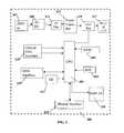
- FIG. 1is a block diagram of a meter reading and control system in accordance with the principles of the invention
- FIG. 2is a block diagram of a power meter in accordance with the principles of the invention.
- FIGS. 3 and 4are flow charts illustrating a method of remotely configuring individual power meters in accordance with the principles of the invention
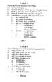
- FIGS. 5, 6 , and 7are tables of functions provided in accordance with the invention.
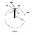
- FIG. 8illustrates a rotating disk in accordance with the principles of the invention.
- Each utility meteris required to record the electricity consumption at a particular premises.
- the advanced metering provided by a time of use meterin accordance with the principles of the invention, it is possible to support a number of different pricing plans. These plans vary the cost of electricity of the consumer according to the time of day and/or maximum load that the consumer draws from the utility grid.
- the meter and system described hereallows a utility company to remotely control the schedule programming of individual meters from a central computer. All information relating to calendars, daily schedules (On peak, Off peak, shoulder 1 and shoulder 2 rate time intervals) and seasonal information is downloaded annually from the database server or whenever there is a change required (such as a rate change or if a customer changes from a flat rate kWh plan to a Time of Use plan).
- a new and novel utility meteris provided and a new and novel system and method for acquiring metered information is provided.
- the system in which the meters may be utilizedis shown in FIG. 1 .
- the systemis designated generally at 100 .
- System 100includes a server 101 .
- Server 101is coupled to a data center 103 that includes relational databases in which utility meter acquired data and account information is stored.
- System 100is coupled via a firewall 105 to a computer network that in the embodiment shown is the Internet 111 that has access to utility meters 113 .
- System 100also is accessible via protective firewalls 107 by the utility company's virtual private network 109 .
- Bi-directional communicationoccurs between each utility meter 113 and system 100 via point of presence (POP) 115 .
- POPpoint of presence
- Internet communication devicessuch as personal computer 117 may access meters 113 and system 100 .
- the hardware designis comprised of a controller with program memory, a liquid crystal display to replace the mechanical registers of the retrofitted meter; direction sensing infra-red disk interface, IrDA communications port for diagnostics; non-volatile memory for interval reading storage; a real-time clock for time stamping of data measurements and a serial port to interface with various wired or wireless communication modules.
- the unitfeatures Time of Use (TOU) demand metering as well as flat rate metering; records usage in predefined intervals, such as 15, 30, or 60 minutes, or other interval; stores up to 31 days of 15 minute interval data; is programmable to send information to host computer daily; power failure detection; backward rotation detection.
- the unitcan access dual ISP's to enhance communication reliability through redundancy.
- the meter softwareestablishes an Internet connection to the portal server that, in turn, executes a set of procedures to validate each transaction from the meter to the database server before inserting packet data into the database server. Data integrity and duplication checks are performed in the validation process.
- the softwaremanages field upgrades through the Internet; offers event notification of hardware failure, power up, power outage and tamper/theft detection with notification capabilities; offers diagnostics of event, connect and diagnostics logs.
- Each utility meter 113is capable of measuring energy consumption in real time. Electrical usage readings are taken at programmed predetermined intervals and are stored in a non-volatile memory at the utility meter. Each meter 113 periodically establishes a link to system 100 . In the illustrative embodiment of the invention, the link is via the public telecommunications network. Each meter 113 includes a modem that, in this embodiment of the invention, is controlled to establish a link via the telephone lines at the residence where the utility meter is installed. Meter 113 includes an auto dialer that is under software control at the respective meter 113 to dialup a connection via Internet 111 to system 100 to upload power usage data from meter 113 to system 100 for storage in data center 103 .
- each utility meter 113takes electricity usage data in predetermined intervals that are determined by embedded software in the meter 113 .
- the predetermined intervalsmay be pre-selected at 5, 10, 15, 30, or 60 minutes.
- the usageis calculated in accordance with predetermined quantifications or “buckets” of total power consumed, power consumed in peak times, power consumed in off-peak times; and power consumed during peak/off-peak shoulder periods.
- meter 113communicates to system 100 during night hours of 12 pm to 5 am.
- each utility meter 113is a hybrid electromechanical/electronic meter.
- the electromechanical portionincludes the rotating disk that operates as an induction type squirrel cage motor as described above.
- the register portion of the meteris replaced with a programmable structure.
- the programmable structure 200 of a meter 113 in accordance with the principles of the inventionis shown in FIG. 2 .
- the illustrative embodimentcomprises a printed circuit board or structure 200 that is added to a conventional single-phase electromechanical meter.
- Printed circuit board 200carries the components that are represented in the block diagram of FIG. 2 .
- Structure 200includes a power supply 207 .
- Power supply 207provides direct current power to the various components of structure 200 .
- Power supply 207includes a rectifier 209 coupled to a first voltage regulator 211 that provides a 5 volt d.c. output.
- First regulator 211is coupled to a “super” capacitor 213 .
- Super capacitor 213comprises two 4.7 Farad capacitors. Super capacitor 213 is provided to provide for uninterrupted power to structure 200 for a period of time should there be brief power outages.
- the voltage output of super capacitor 213is coupled to a second voltage regulator 215 .
- Second voltage regulator 215is a 3.6 volt regulator that provides power to the remainder of the circuits of structure 200 .
- An under voltage circuit 217is coupled to the output of second voltage regulator 215 . In the event that the voltage output of second voltage regulator 215 falls to a predetermined voltage level, a trigger signal is generated that is utilized to trigger a reset function.
- Structure 200includes a controller 201 .
- Controller 201is a commercially available microprocessor.
- a real time clock controller 203is controlled by a crystal oscillator is coupled to controller 201 to provide clocking for operation of controller 201 .
- a non-volatile electrically modifiable memory NVM 205(EEPROM, FRAM or other commercially available memory) is coupled to processor 201 .
- An optical disk interface 219is coupled to controller 201 and to the rotating disk of utility meter 113 .
- Optical disk interface 219is optically coupled to the rotating disk and generates signals to CPU 219 to indicate power consumption.
- Structure 200includes an onboard silicon serial number chip 227 .
- Silicon serial number 227is a commercially available product. Each chip is a unique, factory-lasered and tested 64-bit registration number that includes an 8 bit family code, plus a 48-bit serial number plus an 8-bit CRC tester. No two parts are alike.
- One such productis the DS2401 available from Dallas Semiconductor
- Structure 200further includes an optical communication or infrared data access interface 225 .
- IrDA interface 225is capable of communicating with a handheld device.
- Structure 200also includes a wide area network interface 223 that provides one or more of analog modem functionality, cellular telephone modem functionality, satellite communication functionality, 2 way paging functionality, or power line carrier functionality.
- structure 200includes a display module and display driver 229 coupled to controller 201 .
- the display moduleis utilized to provide an electronically generated human readable output of energy consumption.
- display and driver 229may be mounted separate from meter 113 .
- display and driver 229may be mounted inside the customer's premises rather than at meter 113 to thereby permit the customer to more easily see power consumption. By providing a display that is readable within the serviced premises, the owner of the premises may be better able to manage and reduce power consumption.
- meter 113may be coupled to display driver 229 via wireless or wired technology.
- Each printed circuit board 200 and its associated utility meter 113is uniquely identified by the silicon serial number 227 .
- each utility meter 113has an identification number that is assigned to it that is unique to the utility providing service. The identification number is displayed on a nameplate on meter 113 and is displayed in alphanumeric form as well as in a bar code format.
- meter identification number and the corresponding silicon serial numberare transmitted to data center 103 and stored in the database.
- Controller 201stores the identification number in memory. On a command from the operator, controller 201 utilizes modem interface 223 to contact database server 101 to transmit the identification number and silicon serial number to database 103 so that the correlation between the identification number and the silicon serial number may be recorded.
- Data center 103must store information pertaining to rate schedules for each individual service residence/account.
- the rate schedulesmay be flat rate or time of use. If the rate schedule is time of use, then the rate schedule to be implemented is also associated with the individual service residence/account.
- step 301the meter is powered up.
- the metergoes through an initialization and self-test process.
- the initialization and self-testis performed in accordance with software stored in NVM 205 .
- controller 201utilizes modem 223 to establish a TCP/IP connection with server 101 and sends a message to server 101 that it is powered up at step 303 .
- Server 101receives the power up indication.
- Server 101sends an acknowledgement signal back to controller 201 and also transmits the current time to controller 201 .
- controller 201receives the time indication from server 101 and utilizes the time indication to set its internal clock. In addition, controller 201 sends an acknowledgment signal back to server 101 .
- the meter installerhas an installation route sheet that identifies each service premises that is having a meter installed with a premise identification number.
- the premise identification numberis bar coded.
- the installer at step 307scans the bar coded premise identification with his or her handheld unit.
- the handheld unitis then used to transmit the premises identification to controller 201 via IrDA interface 225 at step 307 .
- Controller 201stores the premises identification in NVM 205 and transmits the silicon serial number and premise identification number to server 101 at step 309 .
- Server 101causes the premise identification number to be associated with the silicon serial number in data center 103 .
- server 101detects that the information is provided as a result of a new field installation and utilizes the premise identification number to retrieve schedule and rate information from data center 103 and transmit the schedule and rate information to meter 113 at step 311 .
- the rate informationincludes an indication of whether the rate is a flat rate or time of use rate structure. If the rate is a time of use structure, then calendar information is sent.
- the calendar informationmay include season information and a list of holidays. In addition, for each season, the rate information may include a weekday schedule, a Saturday schedule, a Sunday schedule and a Holiday schedule. If the rate schedule is a flat rate, then a flat rate configuration is sent to meter 113 that includes no calendars and that the power usage is to be accumulated as a total accumulation.
- Meter 113receives the rate information at step 313 and stores it internally in NVM 205 at step 315 . The rate schedule is effected immediately upon receipt.
- controller 201communicates to server 101 via modem 223 .
- Modem 223may operate with any of the cellular telephone system formats that are deployed including GSM or CDMA and including packet or not.
- modem 223is capable of making a direct connection with a remote TCP/IP address as follows as shown in the flow chart of FIG. 4
- controller 201determines that it needs to connect to data center 103 via server 101 .
- the determinationis made either as a result of a regular programmed event such as a daily upload, or for a special event such as a loss of power.
- Controller 201utilizes modem 223 to establish a TCP/IP connection at step 403 to server 101 .
- Sever 101immediately provides an acknowledgment of the connection at step 405 .
- Controller 201via modem 223 sends a message to server 101 along with appropriate data message at step 407 .
- Server 101acknowledges receipt of the data message at step 409 .
- Checksum error detectionis utilized.
- controller 201causes the message to be resent as indicated at step 411 .
- the resend featuremay be repeated for a predetermined number of times if an acknowledgment is not received.
- a handheld unit 150may be used in conjunction with meter 113 .
- Handheld unit 150may be a commercially available PDA or a personal computer.
- the hand held unitincludes software that permits it to provide the user with certain functionality.
- the illustrative embodimentshows an IrDA interface 225 to permit infrared communication between handheld unit 150 and controller 201 .
- the communications between handheld unit 150 and meter 113may be classified by function as useful functions, field programming functions and field diagnostic functions
- PDAPersonal Digital Assistants
- computerwith an infrared output or any other programmable device having an infrared communication port.
- PDA'sthat may be used are any of those that are commercially available such as the Palm Pilot.
- references to PDAinclude not only commercially available PDAs, but may also include any other portable or handheld computer device.
- a properly programmed PDA or computer device 150may be used to communicate with a meter 113 as shown in FIG. 1 .
- the PDA 150is carried to a physical proximity of meter 113 .
- PDA 150utilizes a bar code reader to scan the premise identification bar code and the meter bar code.
- PDA 150is used to locally access meter 113 to make fault logs for meters; to force a meter 113 into a communication mode with server 101 and to read the meter.
- Each PDA 150includes security in that PDA's are periodically programmed with a password that is verified during access to a meter from server 101 . In the event that a password is invalid or expired, communication to server 101 from PDA 150 is blocked.
- the useful type of functionsincludes using handheld unit 150 to set the date and time in meter 113 .
- Handheld unit 150may also be used to force controller 201 to initiate a connection to server 101 to send all available stored data from meter 113 to server 101 , or to force controller 201 to send all previously unset data to server 101 .
- handheld unit 150may be used to cause controller 201 to send a power up message to server 101 .
- Handheld unit 150may be used to set up configuration of controller 201 by providing the premises identification code to controller 201 .
- handheld unit 150may set Internet Service provider information in controller 201 including a username, password and one or more phone numbers for dial up.
- the field programming functions that handheld unit 150 providesmay be loaded in a single message for controller 201 . These field programming functions are listed in Table 2 of FIG. 6 .
- handheld unit 150can provide field diagnostic functionality to cause controller 201 to display a connect log indicating connections made to server 101 .
- handheld unit 150can cause controller 201 to display the states of various information stored in controller 201 memories and NVM 205 .
- the diagnostic information that is obtainable via handheld unit 150is shown in Table 3 of FIG. 7 .
- handheld unit 150In instances that handheld unit 150 initiates communications between controller 201 and server 101 , handheld unit 150 will also transmit a password to controller 201 . The password will be sent to server 101 for verification. In the event that the password fails verification, command information sent to server 101 will not be acted on. The password is loaded into handheld unit 150 and is valid for a predetermined time period after which it must be replaced.
- rotating disk 601includes a matte black stripe 603 painted on it.
- the stripe 603covers approximately 5 to 10% of the one surface 605 of disk 601 .
- the IrDA interfaceincludes two opto-coupler pairs 607 , 609 , each comprising an infrared emitter 611 and a phototransistor 613 that are positioned proximate disk 601 .
- the two opto pairs 607 , 609are spaced apart by less than the width of the black stripe 601 .
- the infrared emitters 611are both pulsed at the same time.
- Each infrared emitter 611is pulsed on for approximately 500 microseconds every 5 milliseconds.
- the output of each phototransistor 613is coupled to an analog to digital converter that is on controller 201 .
- the outputs of the two opto pairs 607 , 609are sampled while the infrared emitters are pulsed but after a brief settling period.
- Controller 201operates in accordance with a program that determines whether each opto pair 607 , 609 is proximate the dark stripe 603 on disk 601 or not. When an opto pair 607 , 609 is proximate stripe 603 , the corresponding phototransistor 613 is “off”.
- disk 601When the opto pair 607 , 609 is proximate the non-black portions of disk 601 , disk 601 reflects the infrared light from emitter 611 back to the corresponding phototransistor 613 of the pair and the phototransistor 613 is “on”.
- the software programoperates as a state machine.
- controller 201determines whether the direction of rotation is forward or backward. Only these two state sequences will occur if the meter 113 is operating properly. Each time controller 201 identifies the occurrence of one of the two state sequences and each time a predetermined state transition occurs, controller 201 will record one revolution. Assuming that controller 201 detects the first state sequence as shown in Table 1 , controller 201 records the revolution as being in a first or forward direction when it detects the state transition from state d to state e. in Table 1 . If controller 201 detects the second state sequence as shown in Table 2 , controller 201 records the revolution as being in the second or backward direction when it detects the state transition from state d. to state e. in Table 2 .
- controller 201accumulates the number of revolutions of disk 601 without accounting for whether the rotation is in the forward or reverse direction.
- each meter 113is configured as a form 2 S type meter Form 2 S is such that the electrical contacts to the power grid and to the served premises are symmetrically configured. Because of the symmetrical configuration, it is possible for the meter to be mounted in the housing upside down. When the meter 113 is placed in the housing upside down, the rotating disk 601 will rotate in the reverse direction. When rotating disk 601 runs backwards, the register is run backwards in conventional meters. More likely than not, a meter 113 that is placed in the housing upside down is the result of an attempt to steal electric power.
- Controller 201includes an alerting function that will flag reversed rotation and provide an indication of the reversal to server 101 .
- Controller 201is programmed to recognize the above patterns and therefore knows what state should occur next, given a direction of rotation. If the pattern does not occur, a hardware failure has occurred and failure detection is indicated. The fault indication is also provided to server 101 .
- Controller 201can be programmed to accumulate both forward and reverse direction power. In the normal instance, a customer would have to have pre-registered with the utility company to provide power back to the utility grid.
Landscapes
- Engineering & Computer Science (AREA)
- Computer Networks & Wireless Communication (AREA)
- Signal Processing (AREA)
- Computer Security & Cryptography (AREA)
- Physics & Mathematics (AREA)
- General Physics & Mathematics (AREA)
- Arrangements For Transmission Of Measured Signals (AREA)
Abstract
Description
| TABLE 1 | |||
| a. | |||
| b. | |||
| c. | |||
| d. | |||
| e. | |||
| TABLE 2 | |||
| a. | |||
| b. | |||
| c. | |||
| d. | |||
| e. | |||
Claims (27)
Priority Applications (1)
| Application Number | Priority Date | Filing Date | Title |
|---|---|---|---|
| US10/262,259US6819098B2 (en) | 2002-10-01 | 2002-10-01 | Utility power meter database |
Applications Claiming Priority (1)
| Application Number | Priority Date | Filing Date | Title |
|---|---|---|---|
| US10/262,259US6819098B2 (en) | 2002-10-01 | 2002-10-01 | Utility power meter database |
Publications (2)
| Publication Number | Publication Date |
|---|---|
| US20040064276A1 US20040064276A1 (en) | 2004-04-01 |
| US6819098B2true US6819098B2 (en) | 2004-11-16 |
Family
ID=32030178
Family Applications (1)
| Application Number | Title | Priority Date | Filing Date |
|---|---|---|---|
| US10/262,259Expired - LifetimeUS6819098B2 (en) | 2002-10-01 | 2002-10-01 | Utility power meter database |
Country Status (1)
| Country | Link |
|---|---|
| US (1) | US6819098B2 (en) |
Cited By (26)
| Publication number | Priority date | Publication date | Assignee | Title |
|---|---|---|---|---|
| US20040239522A1 (en)* | 2003-06-02 | 2004-12-02 | Gallagher Todd John | Remotely accessed electrical metering system |
| US20050033701A1 (en)* | 2003-08-08 | 2005-02-10 | International Business Machines Corporation | System and method for verifying the identity of a remote meter transmitting utility usage data |
| US20050234837A1 (en)* | 2004-02-05 | 2005-10-20 | Venkatesh Ramachandran | Method and system for validation, estimation and editing of daily meter read data |
| US20060001414A1 (en)* | 2004-02-06 | 2006-01-05 | Angerame Richard A | Electric power usage and demand reporting system |
| US20060044158A1 (en)* | 2004-09-02 | 2006-03-02 | Womble Phillip C | Methods and systems for meter reading and high speed data transfer |
| US20070096942A1 (en)* | 2005-10-28 | 2007-05-03 | Electro Industries/Gauge Tech. | Intelligent electronic device having an XML-based graphical interface |
| US20070124253A1 (en)* | 2005-02-04 | 2007-05-31 | Angerame Richard A | Utility services usage and demand reporting system |
| US20080001595A1 (en)* | 2006-06-28 | 2008-01-03 | Computime, Ltd. | Recording and Conveying Energy Consumption and Power Information |
| US20080058997A1 (en)* | 2005-04-08 | 2008-03-06 | Powersecure, Inc. | System and method for interactive generator and building electric load control |
| US20080091770A1 (en)* | 2006-10-12 | 2008-04-17 | Schweitzer Engineering Laboratories, Inc. | Data transfer device for use with an intelligent electronic device (IED) |
| US20090091977A1 (en)* | 2007-10-04 | 2009-04-09 | Arc Innovations Limited | Method and system for updating a stored data value in a non-volatile memory |
| US20090284072A1 (en)* | 2008-05-13 | 2009-11-19 | Everett Joseph Mcneill | Method and system for selective electrical backup to a multi-tenant location |
| WO2009084016A3 (en)* | 2007-12-31 | 2009-12-30 | Makarand Hari Joshi | A device with gsm chip for recording the electrical parameters of cfl lamp |
| US20090322556A1 (en)* | 2003-01-31 | 2009-12-31 | Qwest Communications International Inc. | Transmission of utility data |
| US20100164749A1 (en)* | 2008-12-29 | 2010-07-01 | Power Measurement Ltd. | Automatic Registration of Meters to a Centralized Data System |
| US20110053572A1 (en)* | 2009-09-01 | 2011-03-03 | Qwest Communications International, Inc. | System, Method and Apparatus for Automatic Location-Based Silencing of Wireless Transceivers |
| US20120029710A1 (en)* | 2010-07-30 | 2012-02-02 | Ruchali Dodderi | Intelligent core engine |
| US8620885B1 (en)* | 2009-02-13 | 2013-12-31 | Ecologic Analytics, LLC | Systems, methods and software for adjusting read data from utility meters |
| US8688102B2 (en) | 2006-04-19 | 2014-04-01 | Itron, Inc. | Method and configuring parameters of GPRS-type communication devices over a cellular phone network, and corresponding communications system |
| US8791417B2 (en) | 2009-09-11 | 2014-07-29 | NetESCO LLC | Determining energy consumption in a structure |
| US9130898B2 (en) | 2003-01-31 | 2015-09-08 | Qwest Communications International Inc. | Transmitting utility usage data via a network interface device |
| US9471045B2 (en) | 2009-09-11 | 2016-10-18 | NetESCO LLC | Controlling building systems |
| US10330713B2 (en) | 2012-12-21 | 2019-06-25 | Electro Industries/Gauge Tech | Intelligent electronic device having a touch sensitive user interface |
| US10340696B2 (en) | 2016-10-19 | 2019-07-02 | Powersecure, Inc. | Modular power generation facilities using shipping container-based modules |
| US10362468B2 (en) | 2003-01-31 | 2019-07-23 | Centurylink Intellectual Property Llc | Methods, systems and apparatus for selectively distributing urgent public information |
| US12072210B2 (en) | 2005-10-28 | 2024-08-27 | Ei Electronics Llc | Electronic power meter having an end user customizable display |
Families Citing this family (24)
| Publication number | Priority date | Publication date | Assignee | Title |
|---|---|---|---|---|
| US7248158B2 (en)* | 2000-04-14 | 2007-07-24 | Current Technologies, Llc | Automated meter reading power line communication system and method |
| US6998962B2 (en) | 2000-04-14 | 2006-02-14 | Current Technologies, Llc | Power line communication apparatus and method of using the same |
| EP1371219A4 (en) | 2001-02-14 | 2006-06-21 | Current Tech Llc | Data communication over a power line |
| US7436321B2 (en)* | 2002-12-10 | 2008-10-14 | Current Technologies, Llc | Power line communication system with automated meter reading |
| US7376118B2 (en)* | 2003-09-05 | 2008-05-20 | Itron, Inc. | System and method for optimizing contiguous channel operation with cellular reuse |
| US7627453B2 (en)* | 2005-04-26 | 2009-12-01 | Current Communications Services, Llc | Power distribution network performance data presentation system and method |
| US7769149B2 (en)* | 2006-01-09 | 2010-08-03 | Current Communications Services, Llc | Automated utility data services system and method |
| US20080012724A1 (en)* | 2006-01-30 | 2008-01-17 | Corcoran Kevin F | Power line communications module and method |
| US7779099B2 (en) | 2006-03-16 | 2010-08-17 | Us Beverage Net Inc. | Distributed intelligent systems and methods therefor |
| US8350717B2 (en)* | 2006-06-05 | 2013-01-08 | Neptune Technology Group, Inc. | Fixed network for an automatic utility meter reading system |
| US20080068213A1 (en)* | 2006-07-26 | 2008-03-20 | Cornwall Mark K | Managing serial numbering of encoder-receiver-transmitter devices in automatic meter reading systems |
| US7795877B2 (en)* | 2006-11-02 | 2010-09-14 | Current Technologies, Llc | Power line communication and power distribution parameter measurement system and method |
| WO2008086231A2 (en)* | 2007-01-04 | 2008-07-17 | Itron, Inc. | Utility data collection and reconfigurations in a utility metering system |
| US7957322B2 (en) | 2007-02-02 | 2011-06-07 | Silver Sring Networks, Inc. | Flow-through provisioning in utility AMR/AMI networks |
| US20090125351A1 (en)* | 2007-11-08 | 2009-05-14 | Davis Jr Robert G | System and Method for Establishing Communications with an Electronic Meter |
| US20100026517A1 (en)* | 2008-01-04 | 2010-02-04 | Itron, Inc. | Utility data collection and reconfigurations in a utility metering system |
| ATE516480T1 (en)* | 2008-05-16 | 2011-07-15 | Smartdutch B V | SYSTEM FOR MANAGING UTILITIES |
| US8527612B2 (en)* | 2008-10-31 | 2013-09-03 | Eaton Corporation | Methods, devices and computer program products for configuring network-enabled devices |
| US20100262395A1 (en)* | 2009-04-08 | 2010-10-14 | Manu Sharma | System and Method for Determining a Phase Conductor Supplying Power to a Device |
| US20100262393A1 (en)* | 2009-04-08 | 2010-10-14 | Manu Sharma | System and Method for Determining a Phase Conductor Supplying Power to a Device |
| KR101729019B1 (en) | 2010-10-12 | 2017-04-21 | 삼성전자주식회사 | Power management apparatus, power management system having power management apparatus and method for controlling the same |
| US9000945B2 (en)* | 2010-11-23 | 2015-04-07 | Corinex Communications Corp. | System and method for communicating over power lines |
| CN103780741B (en)* | 2012-10-18 | 2018-03-13 | 腾讯科技(深圳)有限公司 | Prompt the method and mobile device of network speed |
| CN114819020B (en)* | 2022-06-24 | 2022-10-21 | 南京致远物联有限公司 | Multi-platform data fusion remote ammeter installation assistant system and use method thereof |
Citations (8)
| Publication number | Priority date | Publication date | Assignee | Title |
|---|---|---|---|---|
| US6088659A (en)* | 1997-09-11 | 2000-07-11 | Abb Power T&D Company Inc. | Automated meter reading system |
| US6300881B1 (en)* | 1999-06-09 | 2001-10-09 | Motorola, Inc. | Data transfer system and method for communicating utility consumption data over power line carriers |
| US6393341B1 (en)* | 1998-12-07 | 2002-05-21 | Abb Automation Inc. | Architecture neutral device abstraction layer for interfacing devices and applications |
| US6396839B1 (en)* | 1997-02-12 | 2002-05-28 | Abb Automation Inc. | Remote access to electronic meters using a TCP/IP protocol suite |
| US6487457B1 (en)* | 1999-02-12 | 2002-11-26 | Honeywell International, Inc. | Database for a remotely accessible building information system |
| US6510213B1 (en)* | 1998-03-11 | 2003-01-21 | Psg Fertigungs- Und Prozessautomations Gmbh | Unit for the bidirectional detection and transmission of data via modern communication networks |
| US6552525B2 (en)* | 2001-03-14 | 2003-04-22 | General Electric Company | System and method for scheduling and monitoring electrical device usage |
| US6633823B2 (en)* | 2000-07-13 | 2003-10-14 | Nxegen, Inc. | System and method for monitoring and controlling energy usage |
- 2002
- 2002-10-01USUS10/262,259patent/US6819098B2/ennot_activeExpired - Lifetime
Patent Citations (8)
| Publication number | Priority date | Publication date | Assignee | Title |
|---|---|---|---|---|
| US6396839B1 (en)* | 1997-02-12 | 2002-05-28 | Abb Automation Inc. | Remote access to electronic meters using a TCP/IP protocol suite |
| US6088659A (en)* | 1997-09-11 | 2000-07-11 | Abb Power T&D Company Inc. | Automated meter reading system |
| US6510213B1 (en)* | 1998-03-11 | 2003-01-21 | Psg Fertigungs- Und Prozessautomations Gmbh | Unit for the bidirectional detection and transmission of data via modern communication networks |
| US6393341B1 (en)* | 1998-12-07 | 2002-05-21 | Abb Automation Inc. | Architecture neutral device abstraction layer for interfacing devices and applications |
| US6487457B1 (en)* | 1999-02-12 | 2002-11-26 | Honeywell International, Inc. | Database for a remotely accessible building information system |
| US6300881B1 (en)* | 1999-06-09 | 2001-10-09 | Motorola, Inc. | Data transfer system and method for communicating utility consumption data over power line carriers |
| US6633823B2 (en)* | 2000-07-13 | 2003-10-14 | Nxegen, Inc. | System and method for monitoring and controlling energy usage |
| US6552525B2 (en)* | 2001-03-14 | 2003-04-22 | General Electric Company | System and method for scheduling and monitoring electrical device usage |
Cited By (45)
| Publication number | Priority date | Publication date | Assignee | Title |
|---|---|---|---|---|
| US8792626B2 (en)* | 2003-01-31 | 2014-07-29 | Qwest Communications International Inc. | Transmission of utility data |
| US9130898B2 (en) | 2003-01-31 | 2015-09-08 | Qwest Communications International Inc. | Transmitting utility usage data via a network interface device |
| US10362468B2 (en) | 2003-01-31 | 2019-07-23 | Centurylink Intellectual Property Llc | Methods, systems and apparatus for selectively distributing urgent public information |
| US20090322556A1 (en)* | 2003-01-31 | 2009-12-31 | Qwest Communications International Inc. | Transmission of utility data |
| US20040239522A1 (en)* | 2003-06-02 | 2004-12-02 | Gallagher Todd John | Remotely accessed electrical metering system |
| US20050033701A1 (en)* | 2003-08-08 | 2005-02-10 | International Business Machines Corporation | System and method for verifying the identity of a remote meter transmitting utility usage data |
| US7557729B2 (en)* | 2004-02-05 | 2009-07-07 | Ecologic Analytics, LLC | Method and system for validation, estimation and editing of daily meter read data |
| US20050234837A1 (en)* | 2004-02-05 | 2005-10-20 | Venkatesh Ramachandran | Method and system for validation, estimation and editing of daily meter read data |
| US9279700B1 (en) | 2004-02-05 | 2016-03-08 | Landis+Gyr Analytics, Llc | Method for validation, estimation and editing of daily meter read data |
| US7215109B2 (en)* | 2004-02-06 | 2007-05-08 | Utility Programs And Metering, Inc. | Electric power usage and demand reporting system |
| US20060001414A1 (en)* | 2004-02-06 | 2006-01-05 | Angerame Richard A | Electric power usage and demand reporting system |
| US20060044158A1 (en)* | 2004-09-02 | 2006-03-02 | Womble Phillip C | Methods and systems for meter reading and high speed data transfer |
| US7309979B2 (en)* | 2005-02-04 | 2007-12-18 | Utility Programs And Metering Ii Inc. | Utility services usage and demand reporting system |
| US20070124253A1 (en)* | 2005-02-04 | 2007-05-31 | Angerame Richard A | Utility services usage and demand reporting system |
| US20080058997A1 (en)* | 2005-04-08 | 2008-03-06 | Powersecure, Inc. | System and method for interactive generator and building electric load control |
| US12072210B2 (en) | 2005-10-28 | 2024-08-27 | Ei Electronics Llc | Electronic power meter having an end user customizable display |
| US8933815B2 (en)* | 2005-10-28 | 2015-01-13 | Electro Industries/Gauge Tech | Intelligent electronic device having an XML-based graphical interface |
| US20070096942A1 (en)* | 2005-10-28 | 2007-05-03 | Electro Industries/Gauge Tech. | Intelligent electronic device having an XML-based graphical interface |
| US8688102B2 (en) | 2006-04-19 | 2014-04-01 | Itron, Inc. | Method and configuring parameters of GPRS-type communication devices over a cellular phone network, and corresponding communications system |
| US20080001595A1 (en)* | 2006-06-28 | 2008-01-03 | Computime, Ltd. | Recording and Conveying Energy Consumption and Power Information |
| US7590499B2 (en) | 2006-06-28 | 2009-09-15 | Computime, Ltd. | Recording and conveying energy consumption and power information |
| US20080091770A1 (en)* | 2006-10-12 | 2008-04-17 | Schweitzer Engineering Laboratories, Inc. | Data transfer device for use with an intelligent electronic device (IED) |
| US7813176B2 (en) | 2007-10-04 | 2010-10-12 | Arc Innovations Limited | Method and system for updating a stored data value in a non-volatile memory |
| US20090091977A1 (en)* | 2007-10-04 | 2009-04-09 | Arc Innovations Limited | Method and system for updating a stored data value in a non-volatile memory |
| WO2009084016A3 (en)* | 2007-12-31 | 2009-12-30 | Makarand Hari Joshi | A device with gsm chip for recording the electrical parameters of cfl lamp |
| US20090284072A1 (en)* | 2008-05-13 | 2009-11-19 | Everett Joseph Mcneill | Method and system for selective electrical backup to a multi-tenant location |
| US8203462B2 (en)* | 2008-12-29 | 2012-06-19 | Schneider Electric USA, Inc. | Automatic registration of meters to a centralized data system |
| CN102318166B (en)* | 2008-12-29 | 2014-07-09 | 施耐德电气美国股份有限公司 | Detecting device, method and system for automatically configuring detecting device |
| CN102318166A (en)* | 2008-12-29 | 2012-01-11 | 施耐德电气美国股份有限公司 | Automatic Registration of Meters to a Centralized Data System |
| US20100164749A1 (en)* | 2008-12-29 | 2010-07-01 | Power Measurement Ltd. | Automatic Registration of Meters to a Centralized Data System |
| US8620885B1 (en)* | 2009-02-13 | 2013-12-31 | Ecologic Analytics, LLC | Systems, methods and software for adjusting read data from utility meters |
| US8594738B2 (en) | 2009-09-01 | 2013-11-26 | Qwest Communications International Inc. | System, method and apparatus for automatic location-based silencing of wireless transceivers |
| US20110053572A1 (en)* | 2009-09-01 | 2011-03-03 | Qwest Communications International, Inc. | System, Method and Apparatus for Automatic Location-Based Silencing of Wireless Transceivers |
| US9116182B2 (en) | 2009-09-11 | 2015-08-25 | NetESCO LLC | Building material including temperature transducer |
| US8843416B2 (en) | 2009-09-11 | 2014-09-23 | NetESCO LLC | Determining energy consumption in a structure |
| US9207267B2 (en) | 2009-09-11 | 2015-12-08 | NetESCO LLC | Determining energy consumption in a structure |
| US8791417B2 (en) | 2009-09-11 | 2014-07-29 | NetESCO LLC | Determining energy consumption in a structure |
| US9471045B2 (en) | 2009-09-11 | 2016-10-18 | NetESCO LLC | Controlling building systems |
| US10452090B2 (en) | 2009-09-11 | 2019-10-22 | NetESCO LLC | Controlling building systems |
| US8676388B2 (en)* | 2010-07-30 | 2014-03-18 | Accenture Global Services Limited | Intelligent core engine |
| US20120029710A1 (en)* | 2010-07-30 | 2012-02-02 | Ruchali Dodderi | Intelligent core engine |
| US10330713B2 (en) | 2012-12-21 | 2019-06-25 | Electro Industries/Gauge Tech | Intelligent electronic device having a touch sensitive user interface |
| US10340696B2 (en) | 2016-10-19 | 2019-07-02 | Powersecure, Inc. | Modular power generation facilities using shipping container-based modules |
| US10340697B2 (en) | 2016-10-19 | 2019-07-02 | Powersecure, Inc. | Modular power generation facilities using shipping container-based modules |
| US10637250B2 (en) | 2016-10-19 | 2020-04-28 | Powersecure, Inc. | Modular power generation facilities using shipping container-based modules |
Also Published As
| Publication number | Publication date |
|---|---|
| US20040064276A1 (en) | 2004-04-01 |
Similar Documents
| Publication | Publication Date | Title |
|---|---|---|
| US6819098B2 (en) | Utility power meter database | |
| US7747534B2 (en) | Utility power meter, metering system and method | |
| US7020566B2 (en) | Utility power meter | |
| US20030009301A1 (en) | Integrated utility meter-reading, billing, payment and usage management system | |
| US8739148B2 (en) | Automated meter reading system | |
| US20020161536A1 (en) | Internet ready, energy meter business methods | |
| US7274305B1 (en) | Electrical utility communications and control system | |
| US7400264B2 (en) | Automated meter reading system, communication and control network for automated meter reading, meter data collector, and associated methods | |
| US5870140A (en) | System for remote meter viewing and reporting | |
| US6801865B2 (en) | Meter monitoring and tamper protection system and method | |
| US20170016943A1 (en) | Temperature Profiling in an Electricity Meter | |
| US5767790A (en) | Automatic utility meter monitor | |
| US7304587B2 (en) | Automated meter reading system, communication and control network for automated meter reading, meter data collector program product, and associated methods | |
| CA2516307C (en) | A user interface for monitoring remote devices | |
| CA2376580C (en) | Prepayment energy metering system with two-way smart card communications | |
| US20020120569A1 (en) | System and method for communication between remote locations | |
| US20020030604A1 (en) | Telemetry system and method | |
| KR20040009560A (en) | System for remotely reading an meter using data structure grouped | |
| US20040239522A1 (en) | Remotely accessed electrical metering system | |
| JP2009032012A (en) | Electric energy automatic meter reading device and automatic meter reading system | |
| WO2009043065A2 (en) | Remote monitoring system | |
| US20020039069A1 (en) | System and method for remote monitoring of cathodic protection systems | |
| KR20200130103A (en) | Integrated Smart Metering System and Collection Server Therefor | |
| US11770644B2 (en) | Modular data concentrator device for public utility metering systems and method for gathering and managing information | |
| KR100366402B1 (en) | Building Meters Internet Checking Method |
Legal Events
| Date | Code | Title | Description |
|---|---|---|---|
| AS | Assignment | Owner name:POWERONEDATA CORPORATION, ARIZONA Free format text:ASSIGNMENT OF ASSIGNORS INTEREST;ASSIGNORS:VILLICANA, ERNEST;WORTH, STEPHEN;KHOLAY, SATISH C.;REEL/FRAME:013356/0763 Effective date:20020930 | |
| STCF | Information on status: patent grant | Free format text:PATENTED CASE | |
| AS | Assignment | Owner name:EL DORADO INVESTMENT COMPANY,ARIZONA Free format text:SECURITY AGREEMENT;ASSIGNOR:POWERONEDATA, INC.;REEL/FRAME:019254/0444 Effective date:20070502 Owner name:EL DORADO INVESTMENT COMPANY, ARIZONA Free format text:SECURITY AGREEMENT;ASSIGNOR:POWERONEDATA, INC.;REEL/FRAME:019254/0444 Effective date:20070502 | |
| FEPP | Fee payment procedure | Free format text:PAT HOLDER NO LONGER CLAIMS SMALL ENTITY STATUS, ENTITY STATUS SET TO UNDISCOUNTED (ORIGINAL EVENT CODE: STOL); ENTITY STATUS OF PATENT OWNER: LARGE ENTITY | |
| FPAY | Fee payment | Year of fee payment:4 | |
| AS | Assignment | Owner name:POWERONEDATA, INC., ARIZONA Free format text:ASSIGNMENT OF ASSIGNORS INTEREST;ASSIGNOR:POWERONEDATA, INC. AKA POWERONEDATA CORPORATION;REEL/FRAME:020451/0234 Effective date:20080131 Owner name:POWERONEDATA, INC.,ARIZONA Free format text:ASSIGNMENT OF ASSIGNORS INTEREST;ASSIGNOR:POWERONEDATA, INC. AKA POWERONEDATA CORPORATION;REEL/FRAME:020451/0234 Effective date:20080131 | |
| AS | Assignment | Owner name:POWERONEDATA, INC., ARIZONA Free format text:RELEASE BY SECURED PARTY;ASSIGNOR:EL DORADO INVESTMENT COMPANY;REEL/FRAME:021127/0175 Effective date:20080609 Owner name:POWERONEDATA, INC.,ARIZONA Free format text:RELEASE BY SECURED PARTY;ASSIGNOR:EL DORADO INVESTMENT COMPANY;REEL/FRAME:021127/0175 Effective date:20080609 | |
| AS | Assignment | Owner name:ELSTER ELECTRICITY, LLC, NORTH CAROLINA Free format text:ASSIGNMENT OF ASSIGNORS INTEREST;ASSIGNOR:POWERONEDATA, INC.;REEL/FRAME:021266/0757 Effective date:20080610 Owner name:ELSTER ELECTRICITY, LLC,NORTH CAROLINA Free format text:ASSIGNMENT OF ASSIGNORS INTEREST;ASSIGNOR:POWERONEDATA, INC.;REEL/FRAME:021266/0757 Effective date:20080610 | |
| AS | Assignment | Owner name:ELSTER SERVICES, LLC, NORTH CAROLINA Free format text:CORRECTIVE ASSIGNMENT TO CORRECT THE NAME OF THE ASSIGNEE PREVIOUSLY RECORDED ON REEL 021266 FRAME 0757. ASSIGNOR(S) HEREBY CONFIRMS THE CORRECT NAME OF THE ASSIGNEE IS ELSTER SERVICES, LLC.;ASSIGNOR:POWERONEDATA, INC.;REEL/FRAME:021291/0828 Effective date:20080610 Owner name:ELSTER SERVICES, LLC,NORTH CAROLINA Free format text:CORRECTIVE ASSIGNMENT TO CORRECT THE NAME OF THE ASSIGNEE PREVIOUSLY RECORDED ON REEL 021266 FRAME 0757. ASSIGNOR(S) HEREBY CONFIRMS THE CORRECT NAME OF THE ASSIGNEE IS ELSTER SERVICES, LLC;ASSIGNOR:POWERONEDATA, INC.;REEL/FRAME:021291/0828 Effective date:20080610 Owner name:ELSTER SERVICES, LLC, NORTH CAROLINA Free format text:CORRECTIVE ASSIGNMENT TO CORRECT THE NAME OF THE ASSIGNEE PREVIOUSLY RECORDED ON REEL 021266 FRAME 0757. ASSIGNOR(S) HEREBY CONFIRMS THE CORRECT NAME OF THE ASSIGNEE IS ELSTER SERVICES, LLC;ASSIGNOR:POWERONEDATA, INC.;REEL/FRAME:021291/0828 Effective date:20080610 | |
| AS | Assignment | Owner name:ELSTER ELECTRICITY, LLC, NORTH CAROLINA Free format text:ASSIGNMENT OF ASSIGNORS INTEREST;ASSIGNOR:ELSTER SERVICES, LLC;REEL/FRAME:021311/0158 Effective date:20080729 Owner name:ELSTER ELECTRICITY, LLC,NORTH CAROLINA Free format text:ASSIGNMENT OF ASSIGNORS INTEREST;ASSIGNOR:ELSTER SERVICES, LLC;REEL/FRAME:021311/0158 Effective date:20080729 | |
| FEPP | Fee payment procedure | Free format text:PAYOR NUMBER ASSIGNED (ORIGINAL EVENT CODE: ASPN); ENTITY STATUS OF PATENT OWNER: LARGE ENTITY | |
| FPAY | Fee payment | Year of fee payment:8 | |
| FPAY | Fee payment | Year of fee payment:12 |