US6818844B2 - Method and structure for a slug assisted pusher-mode piezoelectrically actuated liquid metal optical switch - Google Patents
Method and structure for a slug assisted pusher-mode piezoelectrically actuated liquid metal optical switchDownload PDFInfo
- Publication number
- US6818844B2 US6818844B2US10/413,070US41307003AUS6818844B2US 6818844 B2US6818844 B2US 6818844B2US 41307003 AUS41307003 AUS 41307003AUS 6818844 B2US6818844 B2US 6818844B2
- Authority
- US
- United States
- Prior art keywords
- liquid metal
- coupled
- slug
- liquid
- actuator
- Prior art date
- Legal status (The legal status is an assumption and is not a legal conclusion. Google has not performed a legal analysis and makes no representation as to the accuracy of the status listed.)
- Expired - Fee Related, expires
Links
Images


Classifications
- H—ELECTRICITY
- H01—ELECTRIC ELEMENTS
- H01H—ELECTRIC SWITCHES; RELAYS; SELECTORS; EMERGENCY PROTECTIVE DEVICES
- H01H29/00—Switches having at least one liquid contact
- H01H29/28—Switches having at least one liquid contact with level of surface of contact liquid displaced by fluid pressure
- H—ELECTRICITY
- H01—ELECTRIC ELEMENTS
- H01H—ELECTRIC SWITCHES; RELAYS; SELECTORS; EMERGENCY PROTECTIVE DEVICES
- H01H29/00—Switches having at least one liquid contact
- H01H2029/008—Switches having at least one liquid contact using micromechanics, e.g. micromechanical liquid contact switches or [LIMMS]
- H—ELECTRICITY
- H01—ELECTRIC ELEMENTS
- H01H—ELECTRIC SWITCHES; RELAYS; SELECTORS; EMERGENCY PROTECTIVE DEVICES
- H01H57/00—Electrostrictive relays; Piezoelectric relays
- H01H2057/006—Micromechanical piezoelectric relay
- H—ELECTRICITY
- H01—ELECTRIC ELEMENTS
- H01H—ELECTRIC SWITCHES; RELAYS; SELECTORS; EMERGENCY PROTECTIVE DEVICES
- H01H57/00—Electrostrictive relays; Piezoelectric relays
Definitions
- This inventionrelates generally to the field of electronic devices and systems, and more specifically to optical switching technology.
- a relay or switchmay be used to change an optical signal from a first state to a second state. In general there may be more than two states. In applications that require a small switch geometry or a large number of switches within a small region, micromachining fabrication techniques may be used to create switches with a small footprint.
- a micromachined switchmay be used in a variety of applications, such as industrial equipment, telecommunications equipment and control of electro-mechanical devices such as ink jet printers.
- Piezoelectric materialshave several unique characteristics.
- a piezoelectric materialcan be made to expand or contract in response to an applied voltage. This is known as the indirect piezoelectric effect.
- the amount of expansion or contraction, the force generated by the expansion or contraction, and the amount of time between successive contractionsare important material properties that influence the application of a piezoelectric material in a particular application.
- Piezoelectric materialalso exhibits a direct piezoelectric effect, in which an electric field is generated in response to an applied force. This electric field may be converted to a voltage if contacts are properly coupled to the piezoelectric material.
- the indirect piezoelectric effectis useful in making or breaking a contact within a switching element, while the direct piezoelectric effect is useful in generating a switching signal in response to an applied force.
- a method and structure for an optical switchis disclosed.
- a liquid-filled chamber coupled to a plurality of optical waveguidesis housed within a solid material.
- Seal belts within the liquid-filled chamberare coupled to the solid material, while piezoelectric elements are coupled to a plurality of membranes.
- the plurality of membranesare coupled to the liquid-filled chamber.
- the plurality of seal beltsare coupled to a plurality of liquid metal globules.
- a slugis coupled to one or more liquid metal globules and coupled to one or more of the plurality of seal belts.
- piezoelectric elementsare actuated, causing membrane elements to be deflected.
- the deflection of the membrane elementschanges a pressure of actuator liquid and the change in pressure of the actuator liquid breaks a liquid metal connection and a slug connection between a first contact and a second contact of the electrical switch, thereby blocking or unblocking one or more optical waveguides.
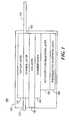
- FIG. 1is a side view of a slug assisted pusher mode liquid metal optical switch, according to certain embodiments of the present invention.
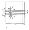
- FIG. 2is a cross sectional drawing of a slug assisted pusher mode liquid metal optical switch, according to certain embodiments of the present invention.
- FIG. 3is a top view of a slug assisted pusher mode liquid metal optical switch with a cap layer removed, according to certain embodiments of the present invention.
- FIG. 4is a top view of a piezoelectric substrate layer of a slug assisted pusher mode liquid metal optical switch, according to certain embodiments of the present invention.
- FIG. 5is a top view of an actuator fluid reservoir layer of a slug assisted pusher mode liquid metal optical switch, according to certain embodiments of the present invention.
- FIG. 6is a top view of a chamber layer of a slug assisted pusher mode liquid metal optical switch, according to certain embodiments of the present invention.
- FIG. 7is a bottom view of the chamber layer of a slug assisted pusher mode liquid metal optical switch, according to certain embodiments of the present invention.
- FIG. 8is a top view of a piezoelectric substrate layer of a slug assisted pusher mode liquid metal optical switch, according to certain embodiments of the present invention.
- FIG. 9is a top view of a channel layer of a slug assisted pusher mode liquid metal optical switch, according to certain embodiments of the present invention.
- FIG. 10is a bottom view of a cap layer of a slug assisted pusher mode liquid metal optical switch, according to certain embodiments of the present invention.
- a liquid metal switchmay be represented using a plurality of layers, wherein the plurality of layers represent layers created during a fabrication of the liquid metal switch.
- Slug assisted pusher mode liquid metal optical switch 105comprises a top cap layer 110 , channel layer 120 , via layer 130 , chamber layer 140 , actuator fluid reservoir layer 150 , piezoelectric substrate layer 160 , and optical waveguide 170 .
- cap layer 110is coupled to channel layer 120
- channel layer 120is coupled to via layer 130
- via layer 130is coupled to chamber layer 140
- chamber layer 140is coupled to actuator fluid reservoir layer 150
- actuator fluid reservoir layer 150is coupled to piezoelectric substrate layer 160
- optical waveguide 170is coupled to one or more of cap layer 110 and channel layer 120 . It is noted that one or more of the layers shown in FIG. 1 may be combined without departing from the spirit and scope of the present invention.
- Cross-sectional drawing 200illustrates how plurality of optical waveguides 170 are coupled to channel 285 and a plurality of seal belts 203 .
- Plurality of seal belts 203are further coupled to encapsulant 275 and channel layer 120 .
- encapsulant 275is composed of an inert, mechanically stable, quick-setting adhesive such as a UV curable epoxy or acrylic.
- plurality of seal belts 203are operable to be coupled to a liquid metal contained in channel 285 thereby blocking one or more of the plurality of optical waveguides 170 .
- Channel 285is further coupled to plurality of vias 270 .
- Plurality of vias 270are within via layer 130 and are operable to provide a path for actuator fluid 250 to enter channel 285 , wherein actuator fluid 250 is located in one or more reservoirs of actuator fluid reservoir layer 150 and in chamber 290 of chamber layer 140 .
- actuating fluid 250is composed of an inert, low viscosity, high boiling point fluid such as 3 M Fluorinert.
- Chamber 290is further coupled to plurality of membranes 295 .
- plurality of membranes 295are located in the chamber layer 140 .
- Plurality of membranes 295are further coupled to the plurality of reservoirs of actuator fluid reservoir layer 150 and further coupled to a plurality of first contacts 230 .
- Plurality of first contacts 230 and plurality of second contacts 240are operable to actuate a corresponding plurality of piezoelectric elements 245 .
- plurality of first contacts 230 and plurality of second contacts 240are isolated by a plurality of dielectric elements 235 .
- Plurality of first contacts 230 and plurality of second contacts 240are further externally accessible by extension of plurality of first contacts 230 and plurality of second contacts 240 through piezoelectric substrate layer 160 .
- FIG. 3a top view 300 of slug assisted pusher mode liquid metal optical switch 105 with cap layer 110 removed is shown, according to certain embodiments of the present invention.
- the top view 300illustrates that channel layer 120 is coupled to plurality of optical waveguides 170 , wherein each optical waveguide of plurality of optical waveguides 170 is coupled to encapsulant 275 .
- Channel 285is coupled to channel layer 120 and comprises plurality of seal belts 203 , liquid metal 320 , slug 325 and plurality of vias 270 .
- liquid metal 320is coupled to two of the plurality of seal belts 203 at a given point in time.
- the liquid metal 320acts as a friction-reducing lubricant.
- plurality of vias 270are collinear with corresponding plurality of optical waveguides 170 .
- Slug 325is coupled to liquid metal 320 , and in certain embodiments of the present invention slug 325 is encapsulated by liquid metal 320 .
- Slug 325may be solid or hollow, and may be composed of a wettable material, such as metallic compounds, ceramic or plastic.
- Plurality of seal bells 203are positioned between the plurality of optical waveguides 170 as shown in FIG. 3 .
- Plurality of vias 270are located at one or more longitudinal ends of channel 285 .
- plurality of vias 270are located between the one or more longitudinal ends of channel 285 and the plurality of seal belts 203 . It is noted that although two optical waveguides and three seal belts are shown in FIG. 3, a greater number of optical waveguides and seal belts could be used without departing from the spirit and scope of the present invention. As illustrated in the figure, via layer 130 has a greater width than channel layer 120 .
- FIG. 4a top view 400 of piezoelectric substrate layer 160 of the slug assisted pusher mode liquid metal optical switch 105 is shown, according to certain embodiments of the present invention.
- the sectional view 445illustrates an orientation of plurality of first contacts 230 and plurality of second contacts 240 .
- fill port 450is operable to be used to fill a reservoir of reservoir layer with actuating fluid 250 .
- actuating fluid 250is filled during an assembly of pusher mode liquid metal optical switch 105 , after which fill port 450 is sealed.
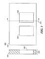
- FIG. 5a top view 500 of actuator fluid reservoir layer 150 of slug assisted pusher mode liquid metal optical switch 105 is shown, according to certain embodiments of the present invention.
- the actuator fluid reservoir layer 150comprises a plurality of fluid chambers 520 , 530 .
- plurality of fluid chambers 520 , 530have a rectangular geometry in top view 500 although other geometries such as circular, square could be used without departing from the spirit and scope of the present invention.
- a cross-sectional view 510is also shown in FIG. 5 .
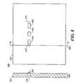
- FIG. 6a top view 600 of chamber layer 140 of slug assisted pusher mode liquid metal optical switch 105 is shown, according to certain embodiments of the present invention.
- FIG. 6illustrates an orientation of plurality of membranes 295 coupled to chamber layer 140 , and a location of a corresponding plurality of fluid ports 615 .
- the plurality of rectangular regions 620 of chamber layer 140have a thickness that is less than a thickness of chamber layer 140 .
- the plurality of fluid ports 615are operable to provide a source of actuator fluid 250 for chamber 290 from reservoirs 520 , 530 .
- a width of plurality of fluid ports 615is chosen so that a deflection of a membrane of plurality of membranes 295 causes a minimal amount of actuator fluid 250 to enter a port of the plurality of fluid ports 615 . More of actuator fluid 250 enters a via of plurality of vias 270 than enters the port of plurality of fluid ports 615 .
- an orientation of plurality of rectangular regions 620 relative to plurality of membranes 295may be different from that shown in FIG. 6 without departing from the spirit and scope of the present invention.
- a first rectangular region of plurality of rectangular regions 620 and a first via of plurality of vias 270could be located on a long axis of a first membrane of plurality of membranes 295 .
- FIG. 7a bottom view 700 of the chamber layer 140 of slug assisted pusher mode liquid metal optical switch 105 is shown, according to certain embodiments of the present invention.
- the bottom view 700illustrates a shape of plurality of membranes 295 relative to chamber layer 140 and plurality of vias 615 .
- a sectional view 705 of chamber layer 140 and a second membrane of plurality of membranes 295is also shown.
- Sectional view 705illustrates that in certain embodiments of the present invention, the second membrane is approximately centered within chamber layer 140 .
- a top view 800 of piezoelectric substrate layer 160 of slug assisted pusher mode liquid metal optical switch 105is shown, according to certain embodiments of the present invention.
- the top view 800illustrates a relative orientation of plurality of seal belts 203 and plurality of vias 270 .
- a via of plurality of vias 270is between any seal belts of plurality of seal belts 203 and a longitudinal end of channel 285 .
- a sectional view 805 of piezoelectric substrate layer 160is also shown. Sectional view 805 illustrates a possible placement of plurality of seal belts 203 with respect to plurality of vias 270 .
- FIG. 9a top view 900 of channel layer 120 of slug assisted pusher mode liquid metal optical switch 105 is shown, according to certain embodiments of the present invention.
- the top view 900illustrates an orientation of plurality of optical waveguides 170 and encapsulant 275 relative to plurality of seal belts 203 and chamber 285 .
- Side view 905illustrates that encapsulant 275 and plurality of optical waveguides 170 are coupled to channel layer 120 using a V-shaped channel in channel layer 120 .
- the V-shaped channelhas a sufficient depth to accommodate plurality of optical waveguides 170 and encapsulant 275 . As illustrated in FIG.
- the plurality of seal belts 203are oriented with respect to channel 285 so that there is a gap between a first longitudinal end of channel 285 and a seal belt of plurality of seal belts 203 .
- This gapis operable to enable a placement of a via of plurality of vias 270 at the longitudinal end of channel 285 .
- FIG. 10a bottom view 1000 of cap layer 110 of slug assisted pusher mode liquid metal optical switch 105 is shown, according to certain embodiments of the present invention.
- the bottom view 1000is shown with plurality of seal belts 203 .
- Certain embodiments of the present inventionuse a pressurization of actuator liquid 250 by actuation of the plurality of piezoelectric elements 245 against plurality of membranes 295 to drive liquid metal 320 and slug 325 from a first two wetting seal belts of plurality of seal belts 203 to a second two wetting seal belts of plurality of seal belts 203 , thereby causing one or more optical waveguides of the plurality of optical waveguides 170 to be blocked or unblocked and changing a state of the slug assisted pusher-mode liquid metal optical switch 105 .
- the slug 325assists in the blocking of the one or more optical waveguides 170 .
- the slug assisted pusher-mode liquid metal optical switch 105latches by a wetting of the one or more seal belts of the plurality of seal belts 203 and a surface tension of the liquid metal 320 causing the liquid metal 320 to stay in a stable position.
- the slug 325is wettable and so may be maintained in a stable position due to the surface tension of the liquid metal and the coupling of the slug 326 to one or more of the plurality of seal belts 203 .
- the plurality of optical waveguides 170have faces that are not wettable by the liquid metal 320 in order to preserve an optical clarity of a signal path of the plurality of optical waveguides 170 .
- the method described hereuses the plurality of piezoelectric elements 245 in a pushing mode.
- a power consumption of slug assisted pusher-mode liquid metal optical switch 105is much lower than a device that uses heated gas to push the liquid metal 320 to a new position since the plurality of piezoelectric elements 245 stores energy rather than dissipating energy.
- One or more of the plurality of piezoelectric elements 245may be used to pull as well as push, so there is a double-acting effect not available with an actuator that is driven solely by a pushing effect of expanding gas.
- the use of pushing piezoelectric elements and pulling piezoelectric elementsis operable to decrease a switching time of slug assisted pusher-mode liquid metal optical switch 105 .
- a first piezoelectric element of plurality of piezoelectric elements 245may be used to push actuator fluid 250 and slug 325 while a second piezoelectric element of plurality of piezoelectric elements 245 may be used to pull actuator fluid 250 and slug 325 .
- the pushing and pullingmay be timed so that a switching time of slug assisted pusher-mode liquid metal optical switch 105 is decreased.
- Liquid metal 320is contained within the channel 285 of the liquid metal channel layer 120 and contacts two of the plurality of seal belt pads 203 .
- an amount and location of the liquid metal 320 in the channel 285is such that only two seal belt pads of plurality of seal belt pads 203 are connected at a time.
- slug 325has a length operable to couple slug 325 to two seal belt pads of plurality of seal belt pads 203 .
- the liquid metal 320can be moved to contact a different set of two seal belt pads of the plurality of seal belt pads 203 by creating an increase in pressure between a first seal belt pad and a second seal belt pad such that the liquid metal 320 breaks and part of the liquid metal moves to couple to the second seal belt pad and a third seal belt pad.
- the slug 325is also moved by the increase in pressure, said increase in pressure operable to be conveyed by the plurality of vias 270 . This is a stable configuration (i.e. latching) because the liquid metal 320 wets the plurality of seal belt pads 203 and is held in place by a surface tension.
- Slug 325is wettable and in certain embodiments of the present invention liquid metal 320 and slug 325 may be moved within the channel 285 substantially more easily than only liquid metal 320 .
- actuator fluid 250is an inert and electrically nonconductive liquid that fills a remaining space in the slug assisted pusher mode liquid metal optical switch 105 .
- the plurality of membranes 295is made of metal, although other materials are possible such as polymers without departing from the spirit and scope of the present invention.
- the plurality of fluid ports 615 that connects the chamber 290 with the plurality of actuator fluid reservoirsare smaller than plurality of vias 270 and assist in causing a pressure pulse to move the liquid metal 320 by directing most of an actuator fluid flow from an actuator action into the channel 285 rather than into a fluid reservoir at a high fluid flow rate, but allows the chamber 285 to refill without disturbing the position of liquid metal 320 at low fluid speeds.
- Slug 325may be solid or hollow depending upon the switching requirements of slug assisted pusher mode liquid metal optical switch 105 . It is noted that liquid metal 320 may be present in channel 285 in a plurality of locations without departing from the spirit and scope of the present invention.
Landscapes
- Physics & Mathematics (AREA)
- Fluid Mechanics (AREA)
- Mechanical Light Control Or Optical Switches (AREA)
Abstract
Description
Claims (39)
Priority Applications (2)
| Application Number | Priority Date | Filing Date | Title |
|---|---|---|---|
| US10/413,070US6818844B2 (en) | 2003-04-14 | 2003-04-14 | Method and structure for a slug assisted pusher-mode piezoelectrically actuated liquid metal optical switch |
| JP2004112439AJP2004318135A (en) | 2003-04-14 | 2004-04-06 | Structure for optical switch and switching method |
Applications Claiming Priority (1)
| Application Number | Priority Date | Filing Date | Title |
|---|---|---|---|
| US10/413,070US6818844B2 (en) | 2003-04-14 | 2003-04-14 | Method and structure for a slug assisted pusher-mode piezoelectrically actuated liquid metal optical switch |
Publications (2)
| Publication Number | Publication Date |
|---|---|
| US20040200708A1 US20040200708A1 (en) | 2004-10-14 |
| US6818844B2true US6818844B2 (en) | 2004-11-16 |
Family
ID=33131357
Family Applications (1)
| Application Number | Title | Priority Date | Filing Date |
|---|---|---|---|
| US10/413,070Expired - Fee RelatedUS6818844B2 (en) | 2003-04-14 | 2003-04-14 | Method and structure for a slug assisted pusher-mode piezoelectrically actuated liquid metal optical switch |
Country Status (2)
| Country | Link |
|---|---|
| US (1) | US6818844B2 (en) |
| JP (1) | JP2004318135A (en) |
Cited By (3)
| Publication number | Priority date | Publication date | Assignee | Title |
|---|---|---|---|---|
| US20040202411A1 (en)* | 2003-04-14 | 2004-10-14 | Wong Marvin Glenn | Method and structure for a pusher-mode piezoelectrically actuated liquid metal optical switch |
| US20050018956A1 (en)* | 2003-07-23 | 2005-01-27 | Tyler Sims | Clean and test for fluid within a reflection optical switch system |
| US20050199480A1 (en)* | 2004-03-11 | 2005-09-15 | Dove Lewis R. | Switch with lid |
Families Citing this family (1)
| Publication number | Priority date | Publication date | Assignee | Title |
|---|---|---|---|---|
| KR101051732B1 (en)* | 2009-11-12 | 2011-07-25 | 한국전자통신연구원 | RF MMS switch using shape change of micro liquid metal droplet |
Citations (84)
| Publication number | Priority date | Publication date | Assignee | Title |
|---|---|---|---|---|
| US2312672A (en) | 1941-05-09 | 1943-03-02 | Bell Telephone Labor Inc | Switching device |
| US2564081A (en) | 1946-05-23 | 1951-08-14 | Babson Bros Co | Mercury switch |
| US3430020A (en) | 1965-08-20 | 1969-02-25 | Siemens Ag | Piezoelectric relay |
| US3529268A (en) | 1967-12-04 | 1970-09-15 | Siemens Ag | Position-independent mercury relay |
| US3600537A (en) | 1969-04-15 | 1971-08-17 | Mechanical Enterprises Inc | Switch |
| US3639165A (en) | 1968-06-20 | 1972-02-01 | Gen Electric | Resistor thin films formed by low-pressure deposition of molybdenum and tungsten |
| US3657647A (en) | 1970-02-10 | 1972-04-18 | Curtis Instr | Variable bore mercury microcoulometer |
| US3955059A (en)* | 1974-08-30 | 1976-05-04 | Graf Ronald E | Electrostatic switch |
| US4103135A (en) | 1976-07-01 | 1978-07-25 | International Business Machines Corporation | Gas operated switches |
| FR2418539A1 (en) | 1978-02-24 | 1979-09-21 | Orega Circuits & Commutation | Liquid contact relays driven by piezoelectric membrane - pref. of polyvinylidene fluoride film for high sensitivity at low power |
| US4200779A (en) | 1977-09-06 | 1980-04-29 | Moscovsky Inzhenerno-Fizichesky Institut | Device for switching electrical circuits |
| US4238748A (en) | 1977-05-27 | 1980-12-09 | Orega Circuits Et Commutation | Magnetically controlled switch with wetted contact |
| FR2458138A1 (en) | 1979-06-01 | 1980-12-26 | Socapex | RELAYS WITH WET CONTACTS AND PLANAR CIRCUIT COMPRISING SUCH A RELAY |
| US4245886A (en) | 1979-09-10 | 1981-01-20 | International Business Machines Corporation | Fiber optics light switch |
| US4336570A (en) | 1980-05-09 | 1982-06-22 | Gte Products Corporation | Radiation switch for photoflash unit |
| US4419650A (en) | 1979-08-23 | 1983-12-06 | Georgina Chrystall Hirtle | Liquid contact relay incorporating gas-containing finely reticular solid motor element for moving conductive liquid |
| US4434337A (en) | 1980-06-26 | 1984-02-28 | W. G/u/ nther GmbH | Mercury electrode switch |
| US4475033A (en) | 1982-03-08 | 1984-10-02 | Northern Telecom Limited | Positioning device for optical system element |
| US4505539A (en) | 1981-09-30 | 1985-03-19 | Siemens Aktiengesellschaft | Optical device or switch for controlling radiation conducted in an optical waveguide |
| US4582391A (en) | 1982-03-30 | 1986-04-15 | Socapex | Optical switch, and a matrix of such switches |
| US4628161A (en) | 1985-05-15 | 1986-12-09 | Thackrey James D | Distorted-pool mercury switch |
| US4652710A (en) | 1986-04-09 | 1987-03-24 | The United States Of America As Represented By The United States Department Of Energy | Mercury switch with non-wettable electrodes |
| US4657339A (en) | 1982-02-26 | 1987-04-14 | U.S. Philips Corporation | Fiber optic switch |
| US4742263A (en) | 1986-08-15 | 1988-05-03 | Pacific Bell | Piezoelectric switch |
| JPS63276838A (en) | 1987-05-06 | 1988-11-15 | Nec Corp | Conductive liquid contact relay |
| US4786130A (en) | 1985-05-29 | 1988-11-22 | The General Electric Company, P.L.C. | Fibre optic coupler |
| US4797519A (en) | 1987-04-17 | 1989-01-10 | Elenbaas George H | Mercury tilt switch and method of manufacture |
| US4804932A (en) | 1986-08-22 | 1989-02-14 | Nec Corporation | Mercury wetted contact switch |
| JPH01294317A (en) | 1988-05-20 | 1989-11-28 | Nec Corp | Conductive liquid contact switch |
| US4988157A (en) | 1990-03-08 | 1991-01-29 | Bell Communications Research, Inc. | Optical switch using bubbles |
| FR2667396A1 (en) | 1990-09-27 | 1992-04-03 | Inst Nat Sante Rech Med | Sensor for pressure measurement in a liquid medium |
| US5278012A (en) | 1989-03-29 | 1994-01-11 | Hitachi, Ltd. | Method for producing thin film multilayer substrate, and method and apparatus for detecting circuit conductor pattern of the substrate |
| EP0593836A1 (en) | 1992-10-22 | 1994-04-27 | International Business Machines Corporation | Near-field photon tunnelling devices |
| US5415026A (en) | 1992-02-27 | 1995-05-16 | Ford; David | Vibration warning device including mercury wetted reed gauge switches |
| US5502781A (en) | 1995-01-25 | 1996-03-26 | At&T Corp. | Integrated optical devices utilizing magnetostrictively, electrostrictively or photostrictively induced stress |
| JPH08125487A (en) | 1994-06-21 | 1996-05-17 | Kinseki Ltd | Piezoelectric vibrator |
| JPH09161640A (en) | 1995-12-13 | 1997-06-20 | Korea Electron Telecommun | Latching type thermal drive micro relay element |
| US5644676A (en) | 1994-06-23 | 1997-07-01 | Instrumentarium Oy | Thermal radiant source with filament encapsulated in protective film |
| US5675310A (en) | 1994-12-05 | 1997-10-07 | General Electric Company | Thin film resistors on organic surfaces |
| US5677823A (en) | 1993-05-06 | 1997-10-14 | Cavendish Kinetics Ltd. | Bi-stable memory element |
| US5751552A (en) | 1995-05-30 | 1998-05-12 | Motorola, Inc. | Semiconductor device balancing thermal expansion coefficient mismatch |
| US5751074A (en) | 1995-09-08 | 1998-05-12 | Edward B. Prior & Associates | Non-metallic liquid tilt switch and circuitry |
| US5828799A (en) | 1995-10-31 | 1998-10-27 | Hewlett-Packard Company | Thermal optical switches for light |
| US5841686A (en) | 1996-11-22 | 1998-11-24 | Ma Laboratories, Inc. | Dual-bank memory module with shared capacitors and R-C elements integrated into the module substrate |
| US5874770A (en) | 1996-10-10 | 1999-02-23 | General Electric Company | Flexible interconnect film including resistor and capacitor layers |
| US5875531A (en) | 1995-03-27 | 1999-03-02 | U.S. Philips Corporation | Method of manufacturing an electronic multilayer component |
| US5886407A (en) | 1993-04-14 | 1999-03-23 | Frank J. Polese | Heat-dissipating package for microcircuit devices |
| US5889325A (en) | 1996-07-25 | 1999-03-30 | Nec Corporation | Semiconductor device and method of manufacturing the same |
| US5912606A (en) | 1998-08-18 | 1999-06-15 | Northrop Grumman Corporation | Mercury wetted switch |
| US5915050A (en) | 1994-02-18 | 1999-06-22 | University Of Southampton | Optical device |
| WO1999046624A1 (en) | 1998-03-09 | 1999-09-16 | Bartels Mikrotechnik Gmbh | Optical switch and modular switch system consisting of optical switching elements |
| US5972737A (en) | 1993-04-14 | 1999-10-26 | Frank J. Polese | Heat-dissipating package for microcircuit devices and process for manufacture |
| US5994750A (en) | 1994-11-07 | 1999-11-30 | Canon Kabushiki Kaisha | Microstructure and method of forming the same |
| US6021048A (en) | 1998-02-17 | 2000-02-01 | Smith; Gary W. | High speed memory module |
| US6180873B1 (en) | 1997-10-02 | 2001-01-30 | Polaron Engineering Limited | Current conducting devices employing mesoscopically conductive liquids |
| US6201682B1 (en) | 1997-12-19 | 2001-03-13 | U.S. Philips Corporation | Thin-film component |
| US6207234B1 (en) | 1998-06-24 | 2001-03-27 | Vishay Vitramon Incorporated | Via formation for multilayer inductive devices and other devices |
| US6212308B1 (en) | 1998-08-03 | 2001-04-03 | Agilent Technologies Inc. | Thermal optical switches for light |
| US6225133B1 (en) | 1993-09-01 | 2001-05-01 | Nec Corporation | Method of manufacturing thin film capacitor |
| US6278541B1 (en) | 1997-01-10 | 2001-08-21 | Lasor Limited | System for modulating a beam of electromagnetic radiation |
| US6304450B1 (en) | 1999-07-15 | 2001-10-16 | Incep Technologies, Inc. | Inter-circuit encapsulated packaging |
| US6320994B1 (en) | 1999-12-22 | 2001-11-20 | Agilent Technolgies, Inc. | Total internal reflection optical switch |
| US6323447B1 (en) | 1998-12-30 | 2001-11-27 | Agilent Technologies, Inc. | Electrical contact breaker switch, integrated electrical contact breaker switch, and electrical contact switching method |
| US6351579B1 (en) | 1998-02-27 | 2002-02-26 | The Regents Of The University Of California | Optical fiber switch |
| US6356679B1 (en) | 2000-03-30 | 2002-03-12 | K2 Optronics, Inc. | Optical routing element for use in fiber optic systems |
| US20020037128A1 (en) | 2000-04-16 | 2002-03-28 | Burger Gerardus Johannes | Micro electromechanical system and method for transmissively switching optical signals |
| US6373356B1 (en) | 1999-05-21 | 2002-04-16 | Interscience, Inc. | Microelectromechanical liquid metal current carrying system, apparatus and method |
| US6396012B1 (en) | 1999-06-14 | 2002-05-28 | Rodger E. Bloomfield | Attitude sensing electrical switch |
| US6396371B2 (en) | 2000-02-02 | 2002-05-28 | Raytheon Company | Microelectromechanical micro-relay with liquid metal contacts |
| US6446317B1 (en) | 2000-03-31 | 2002-09-10 | Intel Corporation | Hybrid capacitor and method of fabrication therefor |
| US6453086B1 (en) | 1999-05-04 | 2002-09-17 | Corning Incorporated | Piezoelectric optical switch device |
| US20020146197A1 (en) | 2001-04-04 | 2002-10-10 | Yoon-Joong Yong | Light modulating system using deformable mirror arrays |
| US20020150323A1 (en) | 2001-01-09 | 2002-10-17 | Naoki Nishida | Optical switch |
| US6470106B2 (en) | 2001-01-05 | 2002-10-22 | Hewlett-Packard Company | Thermally induced pressure pulse operated bi-stable optical switch |
| US20020168133A1 (en) | 2001-05-09 | 2002-11-14 | Mitsubishi Denki Kabushiki Kaisha | Optical switch and optical waveguide apparatus |
| US6487333B2 (en) | 1999-12-22 | 2002-11-26 | Agilent Technologies, Inc. | Total internal reflection optical switch |
| US6512322B1 (en) | 2001-10-31 | 2003-01-28 | Agilent Technologies, Inc. | Longitudinal piezoelectric latching relay |
| US6515404B1 (en) | 2002-02-14 | 2003-02-04 | Agilent Technologies, Inc. | Bending piezoelectrically actuated liquid metal switch |
| US6516504B2 (en) | 1996-04-09 | 2003-02-11 | The Board Of Trustees Of The University Of Arkansas | Method of making capacitor with extremely wide band low impedance |
| US20030035611A1 (en) | 2001-08-15 | 2003-02-20 | Youchun Shi | Piezoelectric-optic switch and method of fabrication |
| US6559420B1 (en) | 2002-07-10 | 2003-05-06 | Agilent Technologies, Inc. | Micro-switch heater with varying gas sub-channel cross-section |
| US6633213B1 (en) | 2002-04-24 | 2003-10-14 | Agilent Technologies, Inc. | Double sided liquid metal micro switch |
| US6647165B2 (en)* | 2001-05-31 | 2003-11-11 | Agilent Technologies, Inc. | Total internal reflection optical switch utilizing a moving droplet |
| US6646527B1 (en)* | 2002-04-30 | 2003-11-11 | Agilent Technologies, Inc. | High frequency attenuator using liquid metal micro switches |
- 2003
- 2003-04-14USUS10/413,070patent/US6818844B2/ennot_activeExpired - Fee Related
- 2004
- 2004-04-06JPJP2004112439Apatent/JP2004318135A/ennot_activeWithdrawn
Patent Citations (87)
| Publication number | Priority date | Publication date | Assignee | Title |
|---|---|---|---|---|
| US2312672A (en) | 1941-05-09 | 1943-03-02 | Bell Telephone Labor Inc | Switching device |
| US2564081A (en) | 1946-05-23 | 1951-08-14 | Babson Bros Co | Mercury switch |
| US3430020A (en) | 1965-08-20 | 1969-02-25 | Siemens Ag | Piezoelectric relay |
| US3529268A (en) | 1967-12-04 | 1970-09-15 | Siemens Ag | Position-independent mercury relay |
| US3639165A (en) | 1968-06-20 | 1972-02-01 | Gen Electric | Resistor thin films formed by low-pressure deposition of molybdenum and tungsten |
| US3600537A (en) | 1969-04-15 | 1971-08-17 | Mechanical Enterprises Inc | Switch |
| US3657647A (en) | 1970-02-10 | 1972-04-18 | Curtis Instr | Variable bore mercury microcoulometer |
| US3955059A (en)* | 1974-08-30 | 1976-05-04 | Graf Ronald E | Electrostatic switch |
| US4103135A (en) | 1976-07-01 | 1978-07-25 | International Business Machines Corporation | Gas operated switches |
| US4238748A (en) | 1977-05-27 | 1980-12-09 | Orega Circuits Et Commutation | Magnetically controlled switch with wetted contact |
| US4200779A (en) | 1977-09-06 | 1980-04-29 | Moscovsky Inzhenerno-Fizichesky Institut | Device for switching electrical circuits |
| FR2418539A1 (en) | 1978-02-24 | 1979-09-21 | Orega Circuits & Commutation | Liquid contact relays driven by piezoelectric membrane - pref. of polyvinylidene fluoride film for high sensitivity at low power |
| FR2458138A1 (en) | 1979-06-01 | 1980-12-26 | Socapex | RELAYS WITH WET CONTACTS AND PLANAR CIRCUIT COMPRISING SUCH A RELAY |
| US4419650A (en) | 1979-08-23 | 1983-12-06 | Georgina Chrystall Hirtle | Liquid contact relay incorporating gas-containing finely reticular solid motor element for moving conductive liquid |
| US4245886A (en) | 1979-09-10 | 1981-01-20 | International Business Machines Corporation | Fiber optics light switch |
| US4336570A (en) | 1980-05-09 | 1982-06-22 | Gte Products Corporation | Radiation switch for photoflash unit |
| US4434337A (en) | 1980-06-26 | 1984-02-28 | W. G/u/ nther GmbH | Mercury electrode switch |
| US4505539A (en) | 1981-09-30 | 1985-03-19 | Siemens Aktiengesellschaft | Optical device or switch for controlling radiation conducted in an optical waveguide |
| US4657339A (en) | 1982-02-26 | 1987-04-14 | U.S. Philips Corporation | Fiber optic switch |
| US4475033A (en) | 1982-03-08 | 1984-10-02 | Northern Telecom Limited | Positioning device for optical system element |
| US4582391A (en) | 1982-03-30 | 1986-04-15 | Socapex | Optical switch, and a matrix of such switches |
| US4628161A (en) | 1985-05-15 | 1986-12-09 | Thackrey James D | Distorted-pool mercury switch |
| US4786130A (en) | 1985-05-29 | 1988-11-22 | The General Electric Company, P.L.C. | Fibre optic coupler |
| US4652710A (en) | 1986-04-09 | 1987-03-24 | The United States Of America As Represented By The United States Department Of Energy | Mercury switch with non-wettable electrodes |
| US4742263A (en) | 1986-08-15 | 1988-05-03 | Pacific Bell | Piezoelectric switch |
| US4804932A (en) | 1986-08-22 | 1989-02-14 | Nec Corporation | Mercury wetted contact switch |
| US4797519A (en) | 1987-04-17 | 1989-01-10 | Elenbaas George H | Mercury tilt switch and method of manufacture |
| JPS63276838A (en) | 1987-05-06 | 1988-11-15 | Nec Corp | Conductive liquid contact relay |
| JPH01294317A (en) | 1988-05-20 | 1989-11-28 | Nec Corp | Conductive liquid contact switch |
| US5278012A (en) | 1989-03-29 | 1994-01-11 | Hitachi, Ltd. | Method for producing thin film multilayer substrate, and method and apparatus for detecting circuit conductor pattern of the substrate |
| US4988157A (en) | 1990-03-08 | 1991-01-29 | Bell Communications Research, Inc. | Optical switch using bubbles |
| FR2667396A1 (en) | 1990-09-27 | 1992-04-03 | Inst Nat Sante Rech Med | Sensor for pressure measurement in a liquid medium |
| US5415026A (en) | 1992-02-27 | 1995-05-16 | Ford; David | Vibration warning device including mercury wetted reed gauge switches |
| EP0593836A1 (en) | 1992-10-22 | 1994-04-27 | International Business Machines Corporation | Near-field photon tunnelling devices |
| US5886407A (en) | 1993-04-14 | 1999-03-23 | Frank J. Polese | Heat-dissipating package for microcircuit devices |
| US5972737A (en) | 1993-04-14 | 1999-10-26 | Frank J. Polese | Heat-dissipating package for microcircuit devices and process for manufacture |
| US5677823A (en) | 1993-05-06 | 1997-10-14 | Cavendish Kinetics Ltd. | Bi-stable memory element |
| US6225133B1 (en) | 1993-09-01 | 2001-05-01 | Nec Corporation | Method of manufacturing thin film capacitor |
| US5915050A (en) | 1994-02-18 | 1999-06-22 | University Of Southampton | Optical device |
| JPH08125487A (en) | 1994-06-21 | 1996-05-17 | Kinseki Ltd | Piezoelectric vibrator |
| US5644676A (en) | 1994-06-23 | 1997-07-01 | Instrumentarium Oy | Thermal radiant source with filament encapsulated in protective film |
| US5994750A (en) | 1994-11-07 | 1999-11-30 | Canon Kabushiki Kaisha | Microstructure and method of forming the same |
| US5849623A (en) | 1994-12-05 | 1998-12-15 | General Electric Company | Method of forming thin film resistors on organic surfaces |
| US5675310A (en) | 1994-12-05 | 1997-10-07 | General Electric Company | Thin film resistors on organic surfaces |
| US5502781A (en) | 1995-01-25 | 1996-03-26 | At&T Corp. | Integrated optical devices utilizing magnetostrictively, electrostrictively or photostrictively induced stress |
| US5875531A (en) | 1995-03-27 | 1999-03-02 | U.S. Philips Corporation | Method of manufacturing an electronic multilayer component |
| US5751552A (en) | 1995-05-30 | 1998-05-12 | Motorola, Inc. | Semiconductor device balancing thermal expansion coefficient mismatch |
| US5751074A (en) | 1995-09-08 | 1998-05-12 | Edward B. Prior & Associates | Non-metallic liquid tilt switch and circuitry |
| US5828799A (en) | 1995-10-31 | 1998-10-27 | Hewlett-Packard Company | Thermal optical switches for light |
| JPH09161640A (en) | 1995-12-13 | 1997-06-20 | Korea Electron Telecommun | Latching type thermal drive micro relay element |
| US6516504B2 (en) | 1996-04-09 | 2003-02-11 | The Board Of Trustees Of The University Of Arkansas | Method of making capacitor with extremely wide band low impedance |
| US5889325A (en) | 1996-07-25 | 1999-03-30 | Nec Corporation | Semiconductor device and method of manufacturing the same |
| US5874770A (en) | 1996-10-10 | 1999-02-23 | General Electric Company | Flexible interconnect film including resistor and capacitor layers |
| US5841686A (en) | 1996-11-22 | 1998-11-24 | Ma Laboratories, Inc. | Dual-bank memory module with shared capacitors and R-C elements integrated into the module substrate |
| US6278541B1 (en) | 1997-01-10 | 2001-08-21 | Lasor Limited | System for modulating a beam of electromagnetic radiation |
| US6180873B1 (en) | 1997-10-02 | 2001-01-30 | Polaron Engineering Limited | Current conducting devices employing mesoscopically conductive liquids |
| US6201682B1 (en) | 1997-12-19 | 2001-03-13 | U.S. Philips Corporation | Thin-film component |
| US6021048A (en) | 1998-02-17 | 2000-02-01 | Smith; Gary W. | High speed memory module |
| US6351579B1 (en) | 1998-02-27 | 2002-02-26 | The Regents Of The University Of California | Optical fiber switch |
| WO1999046624A1 (en) | 1998-03-09 | 1999-09-16 | Bartels Mikrotechnik Gmbh | Optical switch and modular switch system consisting of optical switching elements |
| US6408112B1 (en) | 1998-03-09 | 2002-06-18 | Bartels Mikrotechnik Gmbh | Optical switch and modular switching system comprising of optical switching elements |
| US6207234B1 (en) | 1998-06-24 | 2001-03-27 | Vishay Vitramon Incorporated | Via formation for multilayer inductive devices and other devices |
| US6212308B1 (en) | 1998-08-03 | 2001-04-03 | Agilent Technologies Inc. | Thermal optical switches for light |
| US5912606A (en) | 1998-08-18 | 1999-06-15 | Northrop Grumman Corporation | Mercury wetted switch |
| US6323447B1 (en) | 1998-12-30 | 2001-11-27 | Agilent Technologies, Inc. | Electrical contact breaker switch, integrated electrical contact breaker switch, and electrical contact switching method |
| US6453086B1 (en) | 1999-05-04 | 2002-09-17 | Corning Incorporated | Piezoelectric optical switch device |
| US6373356B1 (en) | 1999-05-21 | 2002-04-16 | Interscience, Inc. | Microelectromechanical liquid metal current carrying system, apparatus and method |
| US6501354B1 (en) | 1999-05-21 | 2002-12-31 | Interscience, Inc. | Microelectromechanical liquid metal current carrying system, apparatus and method |
| US6396012B1 (en) | 1999-06-14 | 2002-05-28 | Rodger E. Bloomfield | Attitude sensing electrical switch |
| US6304450B1 (en) | 1999-07-15 | 2001-10-16 | Incep Technologies, Inc. | Inter-circuit encapsulated packaging |
| US6487333B2 (en) | 1999-12-22 | 2002-11-26 | Agilent Technologies, Inc. | Total internal reflection optical switch |
| US6320994B1 (en) | 1999-12-22 | 2001-11-20 | Agilent Technolgies, Inc. | Total internal reflection optical switch |
| US6396371B2 (en) | 2000-02-02 | 2002-05-28 | Raytheon Company | Microelectromechanical micro-relay with liquid metal contacts |
| US6356679B1 (en) | 2000-03-30 | 2002-03-12 | K2 Optronics, Inc. | Optical routing element for use in fiber optic systems |
| US6446317B1 (en) | 2000-03-31 | 2002-09-10 | Intel Corporation | Hybrid capacitor and method of fabrication therefor |
| US20020037128A1 (en) | 2000-04-16 | 2002-03-28 | Burger Gerardus Johannes | Micro electromechanical system and method for transmissively switching optical signals |
| US6470106B2 (en) | 2001-01-05 | 2002-10-22 | Hewlett-Packard Company | Thermally induced pressure pulse operated bi-stable optical switch |
| US20020150323A1 (en) | 2001-01-09 | 2002-10-17 | Naoki Nishida | Optical switch |
| US20020146197A1 (en) | 2001-04-04 | 2002-10-10 | Yoon-Joong Yong | Light modulating system using deformable mirror arrays |
| US20020168133A1 (en) | 2001-05-09 | 2002-11-14 | Mitsubishi Denki Kabushiki Kaisha | Optical switch and optical waveguide apparatus |
| US6647165B2 (en)* | 2001-05-31 | 2003-11-11 | Agilent Technologies, Inc. | Total internal reflection optical switch utilizing a moving droplet |
| US20030035611A1 (en) | 2001-08-15 | 2003-02-20 | Youchun Shi | Piezoelectric-optic switch and method of fabrication |
| US6512322B1 (en) | 2001-10-31 | 2003-01-28 | Agilent Technologies, Inc. | Longitudinal piezoelectric latching relay |
| US6515404B1 (en) | 2002-02-14 | 2003-02-04 | Agilent Technologies, Inc. | Bending piezoelectrically actuated liquid metal switch |
| US6633213B1 (en) | 2002-04-24 | 2003-10-14 | Agilent Technologies, Inc. | Double sided liquid metal micro switch |
| US6646527B1 (en)* | 2002-04-30 | 2003-11-11 | Agilent Technologies, Inc. | High frequency attenuator using liquid metal micro switches |
| US6559420B1 (en) | 2002-07-10 | 2003-05-06 | Agilent Technologies, Inc. | Micro-switch heater with varying gas sub-channel cross-section |
Non-Patent Citations (5)
| Title |
|---|
| "Integral Power Resistors for Aluminum Substrate," IBM Technical Disclosure Bulletin, Jun. 1984, US, Jun. 1, 1984, p. 827, vol. 27, No. 1B, TDB-ACC-NO: NB8406827, Cross Reference: 0018-8689-27-1B-827. |
| Bhedwar, Homi C. et al. "Ceramic Multilayer Package Fabrication." Electronic Materials Handbook, Nov. 1989, pp. 460-469, vol. 1 Packaging, Section 4: Packages. |
| Jonathan Simon, "A Liquid-Filled Microrelay With A Moving Mercury Microdrop" (Sep., 1997) Journal of Microelectromechinical Systems, vol. 6, No. 3, PP 208-216. |
| Kim, Joonwon et al. "A Micromechanical Switch with Electrostatically Driven Liquid-Metal Droplet." Sensors and Actuators, A: Physical. v 9798, Apr. 1, 2002, 4 pages. |
| Marvin Glenn Wong, "A Piezoelectrically Actuated Liquid Metal Switch", May 2, 2002, patent application (pending), 12 pages of specification, 5 pages of claims, 1 page of abstract, and 10 sheets of drawings (Fig. 1-10). |
Cited By (6)
| Publication number | Priority date | Publication date | Assignee | Title |
|---|---|---|---|---|
| US20040202411A1 (en)* | 2003-04-14 | 2004-10-14 | Wong Marvin Glenn | Method and structure for a pusher-mode piezoelectrically actuated liquid metal optical switch |
| US6961487B2 (en)* | 2003-04-14 | 2005-11-01 | Agilent Technologies, Inc. | Method and structure for a pusher-mode piezoelectrically actuated liquid metal optical switch |
| US20050018956A1 (en)* | 2003-07-23 | 2005-01-27 | Tyler Sims | Clean and test for fluid within a reflection optical switch system |
| US7274840B2 (en)* | 2003-07-23 | 2007-09-25 | Avago Technologies Fiber Ip (Singapore) Pte. Ltd. | Clean and test for fluid within a reflection optical switch system |
| US20050199480A1 (en)* | 2004-03-11 | 2005-09-15 | Dove Lewis R. | Switch with lid |
| US7019236B2 (en)* | 2004-03-11 | 2006-03-28 | Agilent Technologies, Inc. | Switch with lid |
Also Published As
| Publication number | Publication date |
|---|---|
| JP2004318135A (en) | 2004-11-11 |
| US20040200708A1 (en) | 2004-10-14 |
Similar Documents
| Publication | Publication Date | Title |
|---|---|---|
| US7012354B2 (en) | Method and structure for a pusher-mode piezoelectrically actuated liquid metal switch | |
| US6768068B1 (en) | Method and structure for a slug pusher-mode piezoelectrically actuated liquid metal switch | |
| US6818844B2 (en) | Method and structure for a slug assisted pusher-mode piezoelectrically actuated liquid metal optical switch | |
| US6730866B1 (en) | High-frequency, liquid metal, latching relay array | |
| US6765161B1 (en) | Method and structure for a slug caterpillar piezoelectric latching reflective optical relay | |
| US6891315B2 (en) | Shear mode liquid metal switch | |
| US6831532B2 (en) | Push-mode latching relay | |
| US6961487B2 (en) | Method and structure for a pusher-mode piezoelectrically actuated liquid metal optical switch | |
| US6876133B2 (en) | Latching relay with switch bar | |
| US6870111B2 (en) | Bending mode liquid metal switch | |
| US6885133B2 (en) | High frequency bending-mode latching relay | |
| US6879088B2 (en) | Insertion-type liquid metal latching relay array | |
| US6816641B2 (en) | Method and structure for a solid slug caterpillar piezoelectric optical relay | |
| US6946775B2 (en) | Method and structure for a slug assisted longitudinal piezoelectrically actuated liquid metal optical switch | |
| US20040201906A1 (en) | Longitudinal mode solid slug optical latching relay | |
| US6876132B2 (en) | Method and structure for a solid slug caterpillar piezoelectric relay | |
| US20040202408A1 (en) | Pressure actuated optical latching relay | |
| US6903490B2 (en) | Longitudinal mode optical latching relay | |
| US6882088B2 (en) | Bending-mode latching relay |
Legal Events
| Date | Code | Title | Description |
|---|---|---|---|
| AS | Assignment | Owner name:AGILENT TECHNOLGIES, INC., COLORADO Free format text:ASSIGNMENT OF ASSIGNORS INTEREST;ASSIGNORS:WONG, MARVIN GLENN;FONG, ARTHUR;REEL/FRAME:013827/0258 Effective date:20030408 | |
| AS | Assignment | Owner name:AVAGO TECHNOLOGIES GENERAL IP PTE. LTD., SINGAPORE Free format text:ASSIGNMENT OF ASSIGNORS INTEREST;ASSIGNOR:AGILENT TECHNOLOGIES, INC.;REEL/FRAME:017207/0020 Effective date:20051201 | |
| AS | Assignment | Owner name:AVAGO TECHNOLOGIES ECBU IP (SINGAPORE) PTE. LTD., SINGAPORE Free format text:ASSIGNMENT OF ASSIGNORS INTEREST;ASSIGNOR:AVAGO TECHNOLOGIES GENERAL IP (SINGAPORE) PTE. LTD.;REEL/FRAME:017675/0518 Effective date:20060127 Owner name:AVAGO TECHNOLOGIES ECBU IP (SINGAPORE) PTE. LTD.,S Free format text:ASSIGNMENT OF ASSIGNORS INTEREST;ASSIGNOR:AVAGO TECHNOLOGIES GENERAL IP (SINGAPORE) PTE. LTD.;REEL/FRAME:017675/0518 Effective date:20060127 Owner name:AVAGO TECHNOLOGIES ECBU IP (SINGAPORE) PTE. LTD., Free format text:ASSIGNMENT OF ASSIGNORS INTEREST;ASSIGNOR:AVAGO TECHNOLOGIES GENERAL IP (SINGAPORE) PTE. LTD.;REEL/FRAME:017675/0518 Effective date:20060127 | |
| FPAY | Fee payment | Year of fee payment:4 | |
| FPAY | Fee payment | Year of fee payment:8 | |
| AS | Assignment | Owner name:AVAGO TECHNOLOGIES GENERAL IP (SINGAPORE) PTE. LTD Free format text:MERGER;ASSIGNOR:AVAGO TECHNOLOGIES ECBU IP (SINGAPORE) PTE. LTD.;REEL/FRAME:030369/0528 Effective date:20121030 | |
| AS | Assignment | Owner name:AVAGO TECHNOLOGIES GENERAL IP (SINGAPORE) PTE. LTD Free format text:CORRECTIVE ASSIGNMENT TO CORRECT THE NAME OF THE ASSIGNEE PREVIOUSLY RECORDED ON REEL 017207 FRAME 0020. ASSIGNOR(S) HEREBY CONFIRMS THE ASSIGNMENT;ASSIGNOR:AGILENT TECHNOLOGIES, INC.;REEL/FRAME:038633/0001 Effective date:20051201 | |
| REMI | Maintenance fee reminder mailed | ||
| LAPS | Lapse for failure to pay maintenance fees | ||
| STCH | Information on status: patent discontinuation | Free format text:PATENT EXPIRED DUE TO NONPAYMENT OF MAINTENANCE FEES UNDER 37 CFR 1.362 | |
| FP | Lapsed due to failure to pay maintenance fee | Effective date:20161116 |